Embed Size (px)
Citation preview
Southwest Microwave, Inc. • Tempe, Arizona 85284 USA • 480-783-0201 • www.southwestmicrowave.com 27
For use with Size 8 contact cavities for circular connectors per MIL-DTL-38999 Series I, III, IV and equivalents having the same contact cavity and interface dimensions.
SSBP CoaxSize & Gender CablesSSBP Coax No.
SSBP Product SelectionSSBP - 8
8P 50600-001P 0.264 braid OD, Harbour LL-285 or LLS-290
8P 50600-002P .141 solid core flex or S/R (any supplier)
8S 51600-001S 0.264 braid OD, Harbour LL-285 or LLS-290
8S
8S
51600-002S .141 solid core flex or S/R (any supplier)
51600-003S .086 solid core flex or S/R (any supplier)
8P 50600-003P .086 solid core flex or S/R (any supplier)
SSBP Size 8 Socket Assembly (Female)
SSBP Size 8 Pin Assembly (Male)
Contact Southwest Microwave for other connectors and cable options, including 75-ohm assemblies.
Contact Southwest Microwave for outline drawings and assembly instructions for specific SSBP coaxes.
Dimensions:
51600-001S
50600-001P
Coax Socket Mating Interface
CableTermination
.98324.97
.2877.28Ø
.0310.79
.62815.95
Cable Locator Viewing Hole
.3147.98�
� .2807.11
Coax Pin Mating Interface
CableTermination
.65116.54
.1854.70Ø
.0310.79
.2967.52
.3147.98�.215
5.46Ø
.1253.18
Cable Locator Viewing Hole
� .2807.11
Micro-D ConnectorsUsing SSBP-20HD
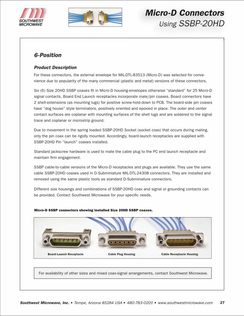
6-Position Product Description
For these connectors, the external envelope for MIL-DTL-83513 (Micro-D) was selected for conve-
nience due to popularity of the many commercial (plastic and metal) versions of these connectors.
Six (6) Size 20HD SSBP coaxes fit in Micro-D housing-envelopes otherwise “standard” for 25 Micro-D
signal contacts. Board End Launch receptacles incorporate male/pin coaxes. Board connectors have
2 shell-extensions (as mounting lugs) for positive screw-hold-down to PCB. The board-side pin coaxes
have “dog house” style terminators, positively oriented and epoxied in place. The outer and center
contact surfaces are coplanar with mounting surfaces of the shell lugs and are soldered to the signal
trace and coplanar or microstrip ground.
Due to movement in the spring loaded SSBP-20HD Socket (socket coax) that occurs during mating,
only the pin coax can be rigidly mounted. Accordingly, board-launch receptacles are supplied with
SSBP-20HD Pin “launch” coaxes installed.
Standard jackscrew hardware is used to mate the cable plug to the PC end launch receptacle and
maintain firm engagement.
SSBP cable-to-cable versions of the Micro-D receptacles and plugs are available. They use the same
cable SSBP-20HD coaxes used in D-Subminiature MIL-DTL-24308 connectors. They are installed and
removed using the same plastic tools as standard D-Subminiature connectors.
Different size housings and combinations of SSBP-20HD coax and signal or grounding contacts can
be provided. Contact Southwest Microwave for your specific needs.
Board-Launch Receptacle Cable Plug Housing Cable Receptacle Housing
Micro-D SSBP connectors showing installed Size 20HD SSBP coaxes.
For availability of other sizes and mixed coax-signal arrangements, contact Southwest Microwave.
Southwest Microwave, Inc. • Tempe, Arizona 85284 USA • 480-783-0201 • www.southwestmicrowave.com28
Micro-D ConnectorsUsing SSBP-20HD
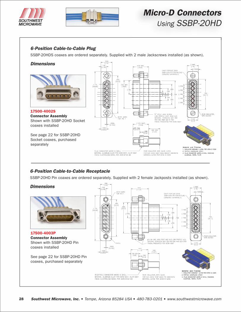
6-Position Cable-to-Cable PlugSSBP-20HDS coaxes are ordered separately. Supplied with 2 male Jackscrews installed (as shown).
Dimensions
6-Position Cable-to-Cable ReceptacleSSBP-20HD Pin coaxes are ordered separately. Supplied with 2 female Jackposts installed (as shown).
Dimensions
17500-4002SConnector AssemblyShown with SSBP-20HD Socket coaxes installed
See page 22 for SSBP-20HD Socket coaxes, purchased separately
17500-4003PConnector AssemblyShown with SSBP-20HD Pin coaxes installed
See page 22 for SSBP-20HD Pin coaxes, purchased separately
Southwest Microwave, Inc. • Tempe, Arizona 85284 USA • 480-783-0201 • www.southwestmicrowave.com 29
Micro-D ConnectorsUsing SSBP-20HD
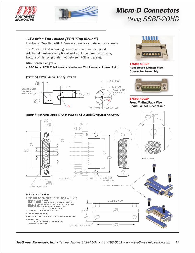
SSBP 6-Position Micro-D Receptacle End Launch Connector Assemby
(View-A) PWB Launch Configuration
USER SUPPLIED SCREWS 2-56 UNC-2A
6-Position End Launch (PCB “Top Mount”)Hardware: Supplied with 2 female screwlocks installed (as shown).
The 2-56 UNC-2A mounting screws are customer-supplied. Additional hardware is optional and would be used on outside/bottom of clamping plate (not between PCB and plate).
Min . Screw Length = ( .250 in . + PCB Thickness + Hardware Thickness + Screw Ext .)
17500-4002PRear Board Launch ViewConnector Assembly
17500-4002PFront Mating Face ViewBoard Launch Receptacle