Embed Size (px)
Citation preview

Document Revision: 4.B Web Configurator
Template Revision: 70
ProtoNode FPC-N38 and ProtoNode FPC-N39 Start-up Guide
For Interfacing Bosch Products: Bosch Buderus SSB800, SSB1000, SSB1000TL
To Building Automation Systems: BACnet MS/TP, BACnet/IP, Modbus TCP/IP, Metasys N2
and LonWorks
APPLICABILITY & EFFECTIVITY
Explains ProtoNode hardware and installation.
The instructions are effective for the above as of March 2018.

Bosch ProtoNode Start-up Guide
Page 2 of 49
Technical Support
Thank you for purchasing the ProtoNode for your Bosch Buderus SSB Boiler.
Please call Bosch for technical support of the ProtoNode product.
SMC does not provide direct support. If Bosch needs to escalate the concern, they will contact Sierra
Monitor Corporation for assistance.
Support Contact Information:
Bosch Thermotechnology Corp.
50 Wentworth Ave.
Londonderry, NH 03053 USA
Customer Service:
1-866-642-3198 or 1-603-552-1100
Contact via website: www.bosch-climate.us/support-center/technical-support/technical-support-form
Website: www.bosch-climate.us

Bosch ProtoNode Start-up Guide
Page 3 of 49
Quick Start Guide
1. Record the information about the unit. (Section 3.1)
2. Set the device’s COM settings and Station Address for each of the devices that are to connect to the
ProtoNode. (Section 3.3)
3. FPC-N38: Select the protocol configuration on the S Bank DIP Switches. (Section 3.4.1)
4. BACnet MS/TP (FPC-N38): Set the MAC Address on the A Bank DIP Switches. (Section 3.5.1)
5. BACnet MS/TP (FPC-N38): Set the baud rate of the BACnet MS/TP field protocol on the B Bank DIP
Switches. (Section 3.5.3)
6. Connect the ProtoNode 6 pin RS-485 connector to the RS-232 network that is connected to each of
the devices. (Section 4.2)
7. Connect the ProtoNode FPC-N38 3 pin RS-485 port to the field protocol cabling, (Section 4.3)
or connect the ProtoNode FPC-N39 2 pin LonWorks port to the field protocol cabling. (Section 4.4)
8. Connect power to the ProtoNode 6 pin connector. (Section 4.5)
9. Use a web browser to access the ProtoNode Web Configurator page to select the profiles of the devices
attached to the ProtoNode and input the Node-ID from each device. Once the devices are selected,
the ProtoNode automatically builds and loads the appropriate configuration. (Section 5.3)
10. Ethernet network (FPC-N38): Use a web browser to access the ProtoNode Web Configurator page to
change the IP Address. No changes to the configuration file are necessary. (Section 5.4)
11. LonWorks (FPC-N39): The ProtoNode must be commissioned on the LonWorks Network. This needs
to be done by the LonWorks administrator using a LonWorks Commissioning tool. (Section 8)

Bosch ProtoNode Start-up Guide
Page 4 of 49
TABLE OF CONTENTS
1 Certification .......................................................................................................................................... 6 1.1 BTL Mark – BACnet® Testing Laboratory ....................................................................................... 6 1.2 LonMark Certification ...................................................................................................................... 6
2 Introduction .......................................................................................................................................... 7 2.1 ProtoNode Gateway ....................................................................................................................... 7
3 ProtoNode Setup.................................................................................................................................. 8 3.1 Record Identification Data .............................................................................................................. 8 3.2 Point Count Capacity and Registers per Device ............................................................................ 8 3.3 Configuring Device Communications ............................................................................................. 9
3.3.1 Input COM Settings on the Device Connected to the ProtoNode ............................................. 9 3.3.2 Set Station Address for the Device Attached to the ProtoNode ............................................... 9
3.4 Selecting the Desired Protocol Configuration ............................................................................... 10 3.4.1 Selecting Desired Field Protocol ............................................................................................. 10
3.5 BMS Network Settings: MAC Address, Device Instance and Baud Rate .................................... 11 3.5.1 BACnet MS/TP (FPC-N38): Setting the MAC Address for BMS Network .............................. 11 3.5.2 BACnet (FPC-N38): Calculating the Default Device Instance ................................................ 12 3.5.3 BACnet MS/TP (FPC-N38): Setting the Baud Rate for BMS Network .................................... 12
4 Interfacing ProtoNode to Devices .................................................................................................... 13 4.1 ProtoNode FPC-N38 and FPC-N39 Showing Connection Ports .................................................. 13 4.2 Device Connections to ProtoNode ............................................................................................... 14 4.3 Serial Network (FPC-N38): Wiring Field Port to RS-485 Network ............................................... 15 4.4 LonWorks (FPC-N39): Wiring LonWorks Devices to the LonWorks Terminal ............................. 15 4.5 Power-Up ProtoNode.................................................................................................................... 16
5 Use the ProtoNode Web Configurator to Setup the Gateway ....................................................... 17 5.1 Connect the PC to ProtoNode via the Ethernet Port .................................................................... 17 5.2 Connecting to the ProtoNode Web Configurator .......................................................................... 18 5.3 Selecting Profiles for Devices Connected to ProtoNode .............................................................. 18 5.4 Ethernet Network: Setting IP Address for the Field Network ....................................................... 20
6 BACnet: Setting Node_Offset to Assign Specific Device Instances ........................................... 22
7 How to Start the Installation Over: Clearing Profiles ..................................................................... 23
8 LonWorks (FPC-N39): Commissioning ProtoNode on a LonWorks Network.............................. 24 8.1 Commissioning ProtoNode FPC-N39 on a LonWorks Network ................................................... 24
8.1.1 Instructions to Upload XIF File from ProtoNode FPC-N39 Using Browser ............................. 24
9 Using the Embedded BACnet Explorer ........................................................................................... 26 9.1 Discover Device List ..................................................................................................................... 27 9.2 View Device Details and Explore Points/Parameters ................................................................... 28
9.2.1 Edit the Present Value Field .................................................................................................... 31
Appendix A Troubleshooting ................................................................................................................... 33 Appendix A.1 Lost or Incorrect IP Address ............................................................................................. 33 Appendix A.2 Viewing Diagnostic Information ........................................................................................ 34 Appendix A.3 Checking Wiring and Settings ........................................................................................... 35 Appendix A.4 LED Diagnostics for Communications Between ProtoNode and Devices ........................ 36 Appendix A.5 Taking Diagnostic Capture with the FieldServer Toolbox ................................................. 37 Appendix A.6 Updating Firmware ............................................................................................................ 40 Appendix A.7 BACnet: Setting Network_Number for More Than one ProtoNode on the Subnet........... 40 Appendix A.8 Securing ProtoNode with Passwords ............................................................................... 41
Appendix B Vendor Information – Bosch ............................................................................................... 42 Appendix B.1 D_Platform Modbus RTU Mappings to BACnet, Metasys N2 and LonWorks .................. 42
Appendix C “A” Bank DIP Switch Settings ............................................................................................ 45 Appendix C.1 “A” Bank DIP Switch Settings ........................................................................................... 45

Bosch ProtoNode Start-up Guide
Page 5 of 49
Appendix D Reference .............................................................................................................................. 48 Appendix D.1 Specifications .................................................................................................................... 48
Appendix D.1.1 Compliance with UL Regulations ............................................................................... 48
Appendix E Limited 2 Year Warranty ...................................................................................................... 49
LIST OF FIGURES
Figure 1: ProtoNode Part Numbers .............................................................................................................. 8 Figure 2: Supported Point Count Capacity ................................................................................................... 8 Figure 3: Registers per Device ..................................................................................................................... 8 Figure 4: Modbus COM Settings ................................................................................................................... 9 Figure 5: S Bank DIP Switches ................................................................................................................... 10 Figure 7: MAC Address DIP Switches ........................................................................................................ 11 Figure 8: BMS Baud Rate DIP Switches ..................................................................................................... 12 Figure 8: BMS Baud Rate ........................................................................................................................... 12 Figure 10: ProtoNode FPC-N38 (upper) and ProtoNode FPC-N39 (lower) ............................................... 13 Figure 11: Power and RS-232 Connections ............................................................................................... 14 Figure 14: Connection from ProtoNode to RS-485 Field Network .............................................................. 15 Figure 15: RS-485 BMS Network EOL Switch ............................................................................................ 15 Figure 16: LonWorks Terminal .................................................................................................................... 15 Figure 15: Required Current Draw for the ProtoNode ................................................................................ 16 Figure 19: Power Connections .................................................................................................................... 16 Figure 18: Web Configurator Showing no Active Profiles ........................................................................... 18 Figure 19: Web Configurator Showing Available Profiles for Selection ...................................................... 19 Figure 20: Web Configurator Showing Active Profile Additions .................................................................. 19 Figure 20: Web Configurator Screen .......................................................................................................... 20 Figure 21: Changing IP Address via FS-GUI .............................................................................................. 21 Figure 22: Web Configurator Node Offset Field.......................................................................................... 22 Figure 23: Active Profiles ............................................................................................................................ 22 Figure 24: LonWorks Service Pin Location ................................................................................................. 24 Figure 25: Sample of Fserver.XIF File Generated ...................................................................................... 25 Figure 26: FS-GUI BACnet Explorer Button ............................................................................................... 26 Figure 27: BACnet Explorer Login Page ..................................................................................................... 26 Figure 28: BACnet Explorer Page ............................................................................................................... 27 Figure 29: Discovery Window ..................................................................................................................... 27 Figure 30: Device List ................................................................................................................................. 28 Figure 31: Device Sub-items ....................................................................................................................... 28 Figure 32: Full Device Sub-items ................................................................................................................ 29 Figure 33: Simplified Device Details ........................................................................................................... 29 Figure 34: Additional Device Details ........................................................................................................... 30 Figure 35: Highlighted Present Value ......................................................................................................... 31 Figure 36: Write Property Window .............................................................................................................. 31 Figure 37: Updated Present Value .............................................................................................................. 32 Figure 38: Ethernet Port Location ............................................................................................................... 33 Figure 39: Error Messages Screen ............................................................................................................. 34 Figure 40: Diagnostic LEDs ........................................................................................................................ 36 Figure 41: Ethernet Port Location ............................................................................................................... 37 Figure 43: Web Configurator – Network Number Field ............................................................................... 40 Figure 44: FS-GUI Passwords Page ........................................................................................................... 41 Figure 45: Password Recovery Page ......................................................................................................... 41 Figure 45: Specifications ............................................................................................................................. 48

Bosch ProtoNode Start-up Guide
Page 6 of 49
1 CERTIFICATION
1.1 BTL Mark – BACnet®1 Testing Laboratory
1.2 LonMark Certif ication
1 BACnet is a registered trademark of ASHRAE
The BTL Mark on ProtoNode is a symbol that indicates that a product has
passed a series of rigorous tests conducted by an independent laboratory
which verifies that the product correctly implements the BACnet features
claimed in the listing. The mark is a symbol of a high-quality BACnet product.
Go to www.BACnetInternational.net for more information about the BACnet
Testing Laboratory. Click here for the BACnet PIC Statement.
LonMark International is the recognized authority for certification, education,
and promotion of interoperability standards for the benefit of manufacturers,
integrators and end users. LonMark International has developed extensive
product certification standards and tests to provide the integrator and user
with confidence that products from multiple manufacturers utilizing LonMark
devices work together. Sierra Monitor has more LonMark Certified gateways
than any other gateway manufacturer, including the ProtoCessor,
ProtoCarrier and ProtoNode for OEM applications and the full featured,
configurable gateways.
Bosch ProtoNode Start-up Guide
Page 7 of 49
2 INTRODUCTION
2.1 ProtoNode Gateway
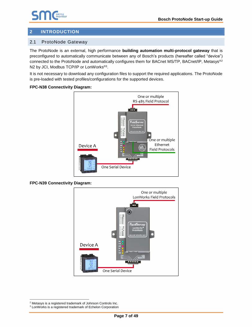
The ProtoNode is an external, high performance building automation multi-protocol gateway that is
preconfigured to automatically communicate between any of Bosch’s products (hereafter called “device”)
connected to the ProtoNode and automatically configures them for BACnet MS/TP, BACnet/IP, Metasys®2
N2 by JCI, Modbus TCP/IP or LonWorks®3.
It is not necessary to download any configuration files to support the required applications. The ProtoNode
is pre-loaded with tested profiles/configurations for the supported devices.
FPC-N38 Connectivity Diagram:
FPC-N39 Connectivity Diagram:
2 Metasys is a registered trademark of Johnson Controls Inc. 3 LonWorks is a registered trademark of Echelon Corporation

Bosch ProtoNode Start-up Guide
Page 8 of 49
3 PROTONODE SETUP
3.1 Record Identif ication Data
Each ProtoNode has a unique part number located on the side or the back of the unit. This number should
be recorded, as it may be required for technical support. The numbers are as follows:
Model Part Number
ProtoNode N38 FPC-N38-1689
ProtoNode N39 FPC-N39-1690
Figure 1: ProtoNode Part Numbers
• FPC-N38 units have the following 3 ports: RS-485 + Ethernet + RS-232
• FPC-N39 units have the following 3 ports: LonWorks + Ethernet + RS-232
3.2 Point Count Capacity and Registers per Device
The total number of registers presented by all the devices attached to the ProtoNode cannot exceed:
Part number Total Registers
FPC-N38-1689 1,500
FPC-N39-1690 1,500
Figure 2: Supported Point Count Capacity
Devices Registers Per Device
D_Platform 1 managing boiler (D_Plat_1_Blr)
63
D_Platform 1 managing & 1 dependent boiler (D_Plat_2_Blr)
91
D_Platform 1 managing & 2 dependent boilers (D_Plat_3_Blr)
119
D_Platform 1 managing & 3 dependent boilers (D_Plat_4_Blr)
147
Figure 3: Registers per Device

Bosch ProtoNode Start-up Guide
Page 9 of 49
3.3 Configuring Device Communications
3.3.1 Input COM Settings on the Device Connected to the ProtoNode
• The connected serial device MUST have the same Baud Rate, Data Bits, Stop Bits, and
Parity settings as the ProtoNode.
• Figure 4 specifies the device serial port settings required to communicate with the ProtoNode.
Port Setting Device
Protocol Modbus RTU
Baud Rate 9600
Parity None
Data Bits 8
Stop Bits 2
Figure 4: Modbus COM Settings
3.3.2 Set Station Address for the Device Attached to the ProtoNode
• Set Station Address for the device attached to ProtoNode to 1.
NOTE: The Metasys N2 and Modbus TCP/IP field protocol Station Addresses are automatically set
to be the same value as the Station Address of the device.

Bosch ProtoNode Start-up Guide
Page 10 of 49
3.4 Selecting the Desired Protocol Configuration
3.4.1 Selecting Desired Field Protocol
• ProtoNode FPC-N38 units use the “S” bank of DIP switches (S0 – S3) to select the protocol
configuration.
o See the table in Figure 5 for the switch settings for the ProtoNode.
o The OFF position is when the DIP switches are set closest to the outside of the box.
• ProtoNode FPC-N39 units do not use the “S” bank DIP switches (S0 – S3) to select a protocol.
o On ProtoNode FPC-N39 units, these switches are disabled; the field protocol is always
LonWorks.
NOTE: When setting DIP switches, ensure that power to the board is OFF.
ProtoNode FPC-N38 S Bank DIP Switches
Profile S0 S1 S2 S3
BACnet/IP Off Off Off Off
BACnet MS/TP On Off Off Off
Metasys N2 Off On Off Off
Modbus TCP/IP On On Off Off
BACnet MS/TP (single node) Off Off On Off
S0 – S3 DIP Switches S Bank DIP Switch Location
Profile Settings for ProtoNode
Figure 5: S Bank DIP Switches
S0
S1
S2
S3
Off On

Bosch ProtoNode Start-up Guide
Page 11 of 49
3.5 BMS Network Settings: MAC Address, Device Instance and Baud Rate
3.5.1 BACnet MS/TP (FPC-N38): Setting the MAC Address for BMS Network
• Set the BACnet MS/TP MAC Address of the ProtoNode to a value between 1 to 127 (MAC Master
Addresses); this is so that the BMS front end can find the ProtoNode via BACnet Auto-Discovery.
NOTE: Never set a BACnet MS/TP MAC Address from 128 to 255. Addresses from 128 to 255 are Slave
Addresses and can not be discovered by BMS front ends that support Auto-Discovery of BACnet
MS/TP devices.
• Set “A” bank DIP switches A0 – A7 to assign a MAC Address to the ProtoNode for BACnet MS/TP.
• Refer to Appendix C.1 for the complete range of MAC Addresses and DIP switch settings.
NOTE: When using Metasys N2 and Modbus TCP/IP, the A Bank of DIP switches are disabled and
not used. They should be set to OFF.
A0
A1
A2
A3
A4
A5
A6
A7
Off On
NOTE: When setting DIP Switches, ensure that power to the board is OFF.
Figure 6: MAC Address DIP Switches

Bosch ProtoNode Start-up Guide
Page 12 of 49
3.5.2 BACnet (FPC-N38): Calculating the Default Device Instance
• The Device Instance value is automatically generated using the following formula:
BACnet Device Instance = (Device Station Address) + (Default Node Offset)
NOTE: The default Node Offset is 50,000.
For example, if Device A has a Station Address of 1 and Device B has a Station Address of 2, then:
BACnet Device Instance A = (1) + (50000) = 50001
BACnet Device Instance B = (2) + (50000) = 50002
NOTE: The Station Address is set in Section 3.3.2.
• To reach a specific BACnet Device Instance result, refer to Section 6.
3.5.3 BACnet MS/TP (FPC-N38): Setting the Baud Rate for BMS Network
• DIP switches B0 – B3 can be used to set the field baud rate of the ProtoNode to match the baud
rate required by the BMS for BACnet MS/TP.
• The ProtoNode baud rate for Metasys N2 is set for 9600. “B” bank DIP switches B0 – B3 are
disabled for Metasys N2 on the ProtoNode FPC-N38.
• DIP switches B0 – B3 are disabled on ProtoNode FPC-N39 (LonWorks).
B0
B1
B2
B3
Off On
NOTE: When setting DIP switches, ensure that power to the board is OFF.
3.5.3.1 Baud Rate DIP Switch Selection
Baud B0 B1 B2 B3
9600 On On On Off
19200 Off Off Off On
38400* On On Off On
57600 Off Off On On
76800 On Off On On
Figure 8: BMS Baud Rate
* Factory default setting = 38400
Figure 7: BMS Baud Rate DIP Switches
Bosch ProtoNode Start-up Guide
Page 13 of 49
4 INTERFACING PROTONODE TO DEVICES
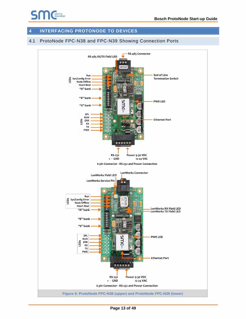
4.1 ProtoNode FPC-N38 and FPC-N39 Showing Connection Ports
Figure 9: ProtoNode FPC-N38 (upper) and ProtoNode FPC-N39 (lower)

Bosch ProtoNode Start-up Guide
Page 14 of 49
4.2 Device Connections to ProtoNode
ProtoNode 6 Pin Phoenix connector:
• The 6 pin Phoenix connector is the same for ProtoNode FPC-N38 (BACnet) and FPC-N39
(LonWorks).
• Pins 1 through 3 are for RS-232 devices. GND must be connected.
o Use standard grounding principles for GND
• Pins 4 through 6 are for power. Do not connect power until Section 4.5.
Device Pins ProtoNode Pin
# Pin
Assignment
Pin RS-232 Rx Pin 1 RS-232 Tx
Pin RS-232 Tx Pin 2 RS-232 Rx
Pin GND Pin 3 GND
Power In (+) Pin 4 V +
Power In (-) Pin 5 V -
Frame Ground Pin 6 FRAME GND
Figure 10: Power and RS-232 Connections
Bosch ProtoNode Start-up Guide
Page 15 of 49
4.3 Serial Network (FPC-N38): Wiring Field Port to RS-485 Network
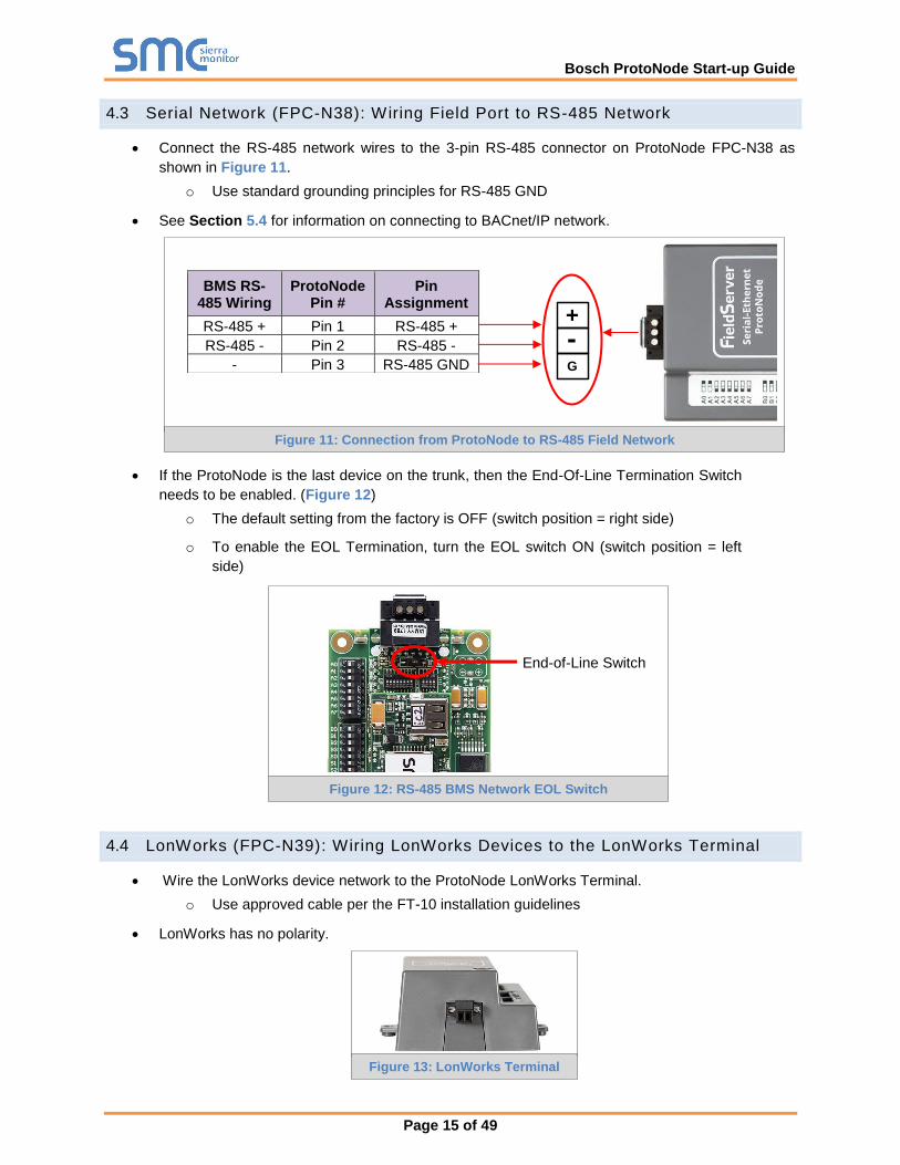
• Connect the RS-485 network wires to the 3-pin RS-485 connector on ProtoNode FPC-N38 as
shown in Figure 11.
o Use standard grounding principles for RS-485 GND
• See Section 5.4 for information on connecting to BACnet/IP network.
• If the ProtoNode is the last device on the trunk, then the End-Of-Line Termination Switch
needs to be enabled. (Figure 12)
o The default setting from the factory is OFF (switch position = right side)
o To enable the EOL Termination, turn the EOL switch ON (switch position = left
side)
4.4 LonWorks (FPC-N39): Wiring LonWorks Devices to the LonWorks Terminal
• Wire the LonWorks device network to the ProtoNode LonWorks Terminal.
o Use approved cable per the FT-10 installation guidelines
• LonWorks has no polarity.
BMS RS-485 Wiring
ProtoNode Pin #
Pin Assignment
RS-485 + Pin 1 RS-485 +
RS-485 - Pin 2 RS-485 -
- Pin 3 RS-485 GND
Figure 13: LonWorks Terminal
Figure 12: RS-485 BMS Network EOL Switch
End-of-Line Switch
G
-
+
Figure 11: Connection from ProtoNode to RS-485 Field Network
Bosch ProtoNode Start-up Guide
Page 16 of 49
4.5 Power-Up ProtoNode
Check power requirements in the table below:
Power Requirement for ProtoNode External Gateway
Current Draw Type
ProtoNode Family 12V DC/AC 24V DC/AC 30V DC
FPC – N38 (Typical) 170mA 100mA 80mA
FPC – N38 (Maximum) 240mA 140mA 100mA
FPC – N39 (Typical) 210mA 130mA 90mA
FPC – N39 (Maximum) 250mA 170mA 110mA
NOTE: These values are ‘nominal’ and a safety margin should be added to the power supply of the host system. A safety margin of 25% is recommended.
Figure 14: Required Current Draw for the ProtoNode
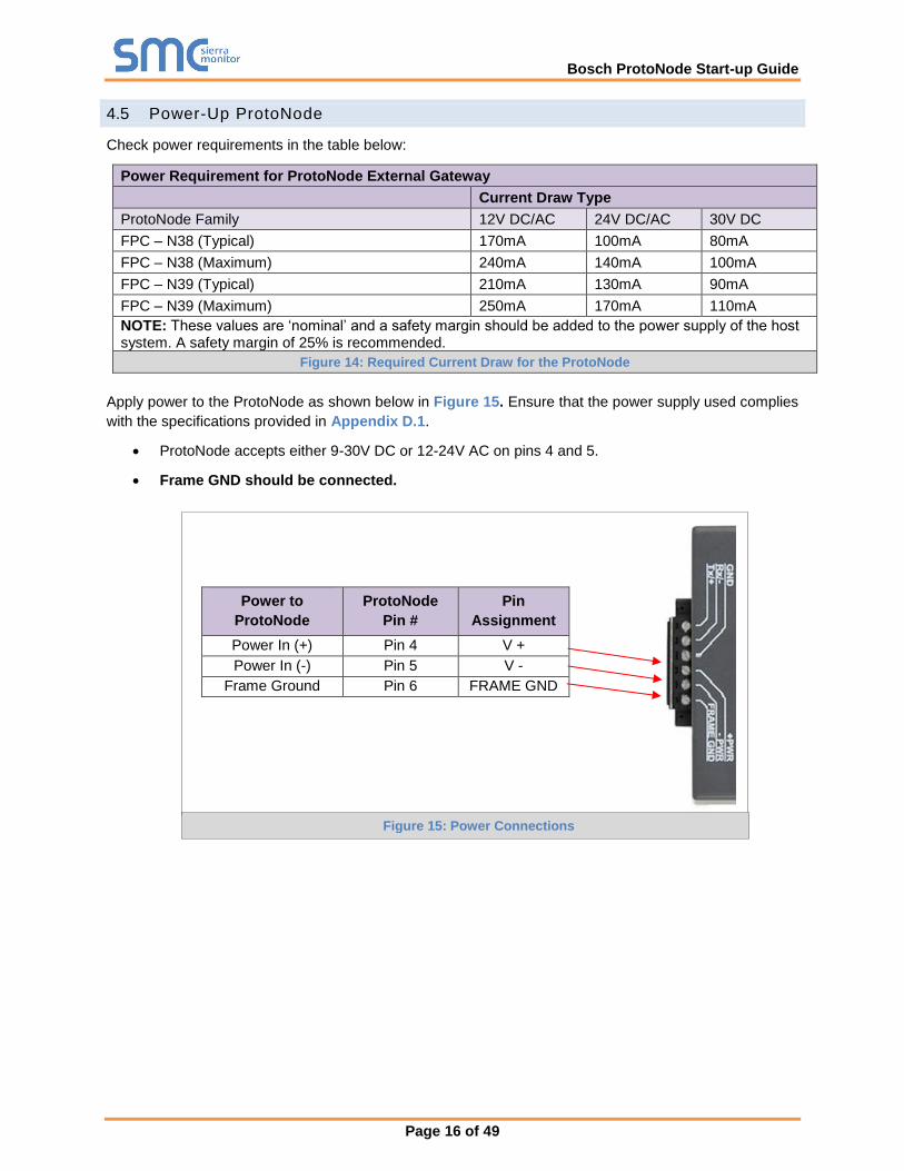
Apply power to the ProtoNode as shown below in Figure 15. Ensure that the power supply used complies
with the specifications provided in Appendix D.1.
• ProtoNode accepts either 9-30V DC or 12-24V AC on pins 4 and 5.
• Frame GND should be connected.
Power to
ProtoNode
ProtoNode
Pin #
Pin
Assignment
Power In (+) Pin 4 V +
Power In (-) Pin 5 V -
Frame Ground Pin 6 FRAME GND
Figure 15: Power Connections
Bosch ProtoNode Start-up Guide
Page 17 of 49
5 USE THE PROTONODE WEB CONFIGURATOR TO SETUP THE GATEWAY
5.1 Connect the PC to ProtoNode via the Ethernet Port
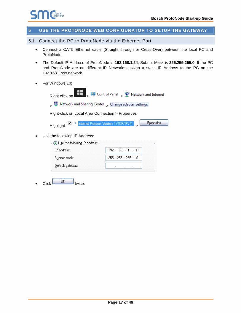
• Connect a CAT5 Ethernet cable (Straight through or Cross-Over) between the local PC and
ProtoNode.
• The Default IP Address of ProtoNode is 192.168.1.24, Subnet Mask is 255.255.255.0. If the PC
and ProtoNode are on different IP Networks, assign a static IP Address to the PC on the
192.168.1.xxx network.
• For Windows 10:
Right click on > >
> >
Right-click on Local Area Connection > Properties
Highlight >
• Use the following IP Address:
• Click twice.

Bosch ProtoNode Start-up Guide
Page 18 of 49
5.2 Connecting to the ProtoNode Web Configurator
After setting a local PC on the same subnet as the ProtoNode (Section 5.1), open a web browser on the
PC and enter the IP Address of the ProtoNode; the default address is 192.168.1.24.
NOTE: If the IP Address of the ProtoNode was changed, the assigned IP Address can be
discovered using the FS Toolbox utility. See Appendix A.1 for instructions.
5.3 Selecting Profiles for Devices Connected to ProtoNode
NOTE: If Modbus TCP/IP was selected in Section 3.4 for the Field/BMS protocol, skip this section.
Device profiles are NOT used for Modbus TCP/IP.
• In the Web Configurator, the Active Profiles are shown below the Configuration Parameters.
Figure 16: Web Configurator Showing no Active Profiles

Bosch ProtoNode Start-up Guide
Page 19 of 49
• The Active profiles section lists the currently active device profiles, including previous Web
Configurator additions. This list is empty for new installations, or after clearing all configurations.
(Figure 16)
• To add an active profile to support a device, click the Add button under the Active Profiles heading.
This will present a drop-down box underneath the Current profile column that lists all the available
profiles. (Figure 17)
• For every device that is added, assign a unique Node-ID. This specification must match the device’s
network settings.
NOTE: If multiple devices are connected to the ProtoNode, set the BACnet Virtual Server Nodes
field to “Yes”; otherwise leave the field on the default “No” setting.
• Once the Profile for the device has been selected from the drop-down list, enter the value of the
device’s Node-ID which was assigned in Section 3.3.2.
• Then press the “Submit” button to add the Profile to the list of devices to be configured.
• Repeat this process until all the devices have been added.
• Completed additions are listed under “Active Profiles” as shown in Figure 18.
Figure 17: Web Configurator Showing Available Profiles for Selection
Figure 18: Web Configurator Showing Active Profile Additions
Bosch ProtoNode Start-up Guide
Page 20 of 49
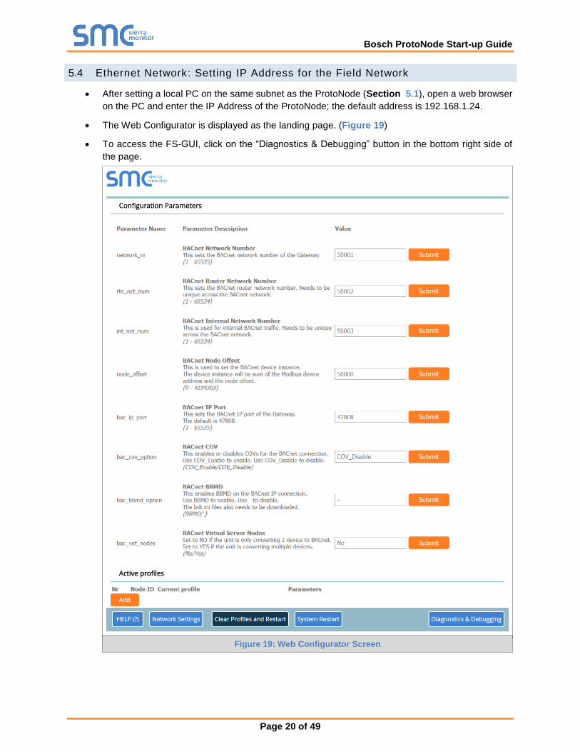
5.4 Ethernet Network: Setting IP Address for the Field Network
• After setting a local PC on the same subnet as the ProtoNode (Section 5.1), open a web browser
on the PC and enter the IP Address of the ProtoNode; the default address is 192.168.1.24.
• The Web Configurator is displayed as the landing page. (Figure 19)
• To access the FS-GUI, click on the “Diagnostics & Debugging” button in the bottom right side of
the page.
Figure 19: Web Configurator Screen
Bosch ProtoNode Start-up Guide
Page 21 of 49
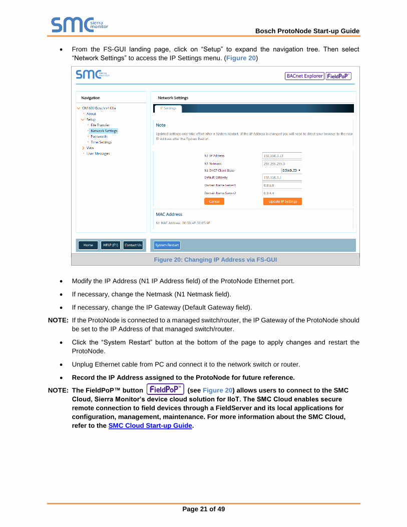
• From the FS-GUI landing page, click on “Setup” to expand the navigation tree. Then select
“Network Settings” to access the IP Settings menu. (Figure 20)
• Modify the IP Address (N1 IP Address field) of the ProtoNode Ethernet port.
• If necessary, change the Netmask (N1 Netmask field).
• If necessary, change the IP Gateway (Default Gateway field).
NOTE: If the ProtoNode is connected to a managed switch/router, the IP Gateway of the ProtoNode should
be set to the IP Address of that managed switch/router.
• Click the “System Restart” button at the bottom of the page to apply changes and restart the
ProtoNode.
• Unplug Ethernet cable from PC and connect it to the network switch or router.
• Record the IP Address assigned to the ProtoNode for future reference.
NOTE: The FieldPoP™ button (see Figure 20) allows users to connect to the SMC
Cloud, Sierra Monitor’s device cloud solution for IIoT. The SMC Cloud enables secure
remote connection to field devices through a FieldServer and its local applications for
configuration, management, maintenance. For more information about the SMC Cloud,
refer to the SMC Cloud Start-up Guide.
Figure 20: Changing IP Address via FS-GUI
Bosch ProtoNode Start-up Guide
Page 22 of 49
6 BACNET: SETTING NODE_OFFSET TO ASSIGN SPECIFIC DEVICE INSTANCES
• After setting a local PC to the same subnet as the ProtoNode (Section 5.1), open a web browser
on the PC and enter the IP Address of the ProtoNode; the default address is 192.168.1.24.
o If the IP Address of the ProtoNode has been changed by previous configuration, the
assigned IP Address will need to be obtained from the network administrator.
o The Web Configurator is displayed as the landing page.
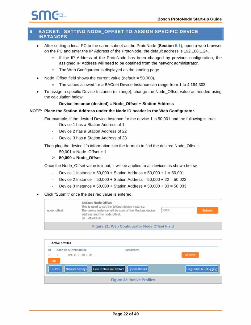
• Node_Offset field shows the current value (default = 50,000).
o The values allowed for a BACnet Device Instance can range from 1 to 4,194,303.
• To assign a specific Device Instance (or range); change the Node_Offset value as needed using
the calculation below:
Device Instance (desired) = Node_Offset + Station Address
NOTE: Place the Station Address under the Node ID header in the Web Configurator.
For example, if the desired Device Instance for the device 1 is 50,001 and the following is true:
- Device 1 has a Station Address of 1
- Device 2 has a Station Address of 22
- Device 3 has a Station Address of 33
Then plug the device 1’s information into the formula to find the desired Node_Offset:
50,001 = Node_Offset + 1
➢ 50,000 = Node_Offset
Once the Node_Offset value is input, it will be applied to all devices as shown below:
- Device 1 Instance = 50,000 + Station Address = 50,000 + 1 = 50,001
- Device 2 Instance = 50,000 + Station Address = 50,000 + 22 = 50,022
- Device 3 Instance = 50,000 + Station Address = 50,000 + 33 = 50,033
• Click “Submit” once the desired value is entered.
Figure 22: Active Profiles
Figure 21: Web Configurator Node Offset Field

Bosch ProtoNode Start-up Guide
Page 23 of 49
7 HOW TO START THE INSTALLATION OVER: CLEARING PROFILES
• After setting a local PC to the same subnet as the ProtoNode (Section 5.1), open a web browser
on the PC and enter the IP Address of the ProtoNode; the default address is 192.168.1.24.
• If the IP Address of the ProtoNode has been changed by previous configuration, the assigned IP
Address will need to be obtained from the network administrator.
• The Web Configurator is displayed as the landing page.
• At the bottom-left of the page, click the “Clear Profiles and Restart” button.
• Once restart is complete, all past profiles discovered and/or added via Web Configurator are
deleted. The unit can now be reinstalled.
Bosch ProtoNode Start-up Guide
Page 24 of 49
8 LONWORKS (FPC-N39): COMMISSIONING PROTONODE ON A LONWORKS NETWORK
Commissioning may only be performed by the LonWorks administrator.
8.1 Commissioning ProtoNode FPC-N39 on a LonWorks Network
During the commissioning process, the LonWorks Administrator may prompt the User to hit the Service Pin
on the ProtoNode FPC-N39 at a specific point (this step occurs at different points of the commissioning
process for each LonWorks Network Management Tool).
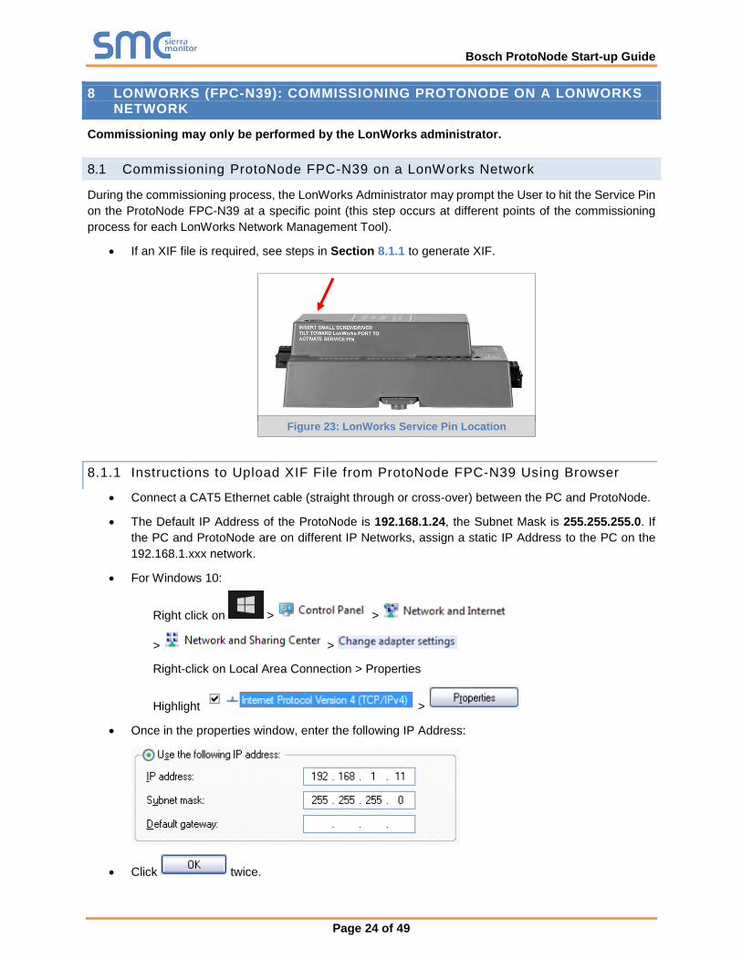
• If an XIF file is required, see steps in Section 8.1.1 to generate XIF.
8.1.1 Instructions to Upload XIF File from ProtoNode FPC-N39 Using Browser
• Connect a CAT5 Ethernet cable (straight through or cross-over) between the PC and ProtoNode.
• The Default IP Address of the ProtoNode is 192.168.1.24, the Subnet Mask is 255.255.255.0. If
the PC and ProtoNode are on different IP Networks, assign a static IP Address to the PC on the
192.168.1.xxx network.
• For Windows 10:
Right click on > >
> >
Right-click on Local Area Connection > Properties
Highlight >
• Once in the properties window, enter the following IP Address:
• Click twice.
Figure 23: LonWorks Service Pin Location

Bosch ProtoNode Start-up Guide
Page 25 of 49
• Open a web browser and go to the following address: [IP Address of ProtoNode]/fserver.xif.
o Example: 192.168.1.24/fserver.xif
• If the web browser prompts to save the file, save the file onto the PC. If the web browser displays
the xif file as a web page, save the file onto the local PC as “fserver.xif”.
Figure 24: Sample of Fserver.XIF File Generated

Bosch ProtoNode Start-up Guide
Page 26 of 49
9 USING THE EMBEDDED BACNET EXPLORER
The embedded Bacnet Explorer allows installers of the OEM product ot validate that their equipment is
working on Bacnet without having to ask the BMS integrator to test the unit.
• To access the embedded BACnet Explorer, go to the FS-GUI page and click the BACnet Explorer
button.
• Then login to the BACnet Explorer page using the supplied username and password.
NOTE: The default user name is “admin” and default password is “admin”.
NOTE: For BACnet/IP, click on the Settings button on the left side of the landing page to ensure
the ProtoNode is on the BACnet/IP network subnet or to configure BBMD.
Figure 25: FS-GUI BACnet Explorer Button
Figure 26: BACnet Explorer Login Page
Bosch ProtoNode Start-up Guide
Page 27 of 49
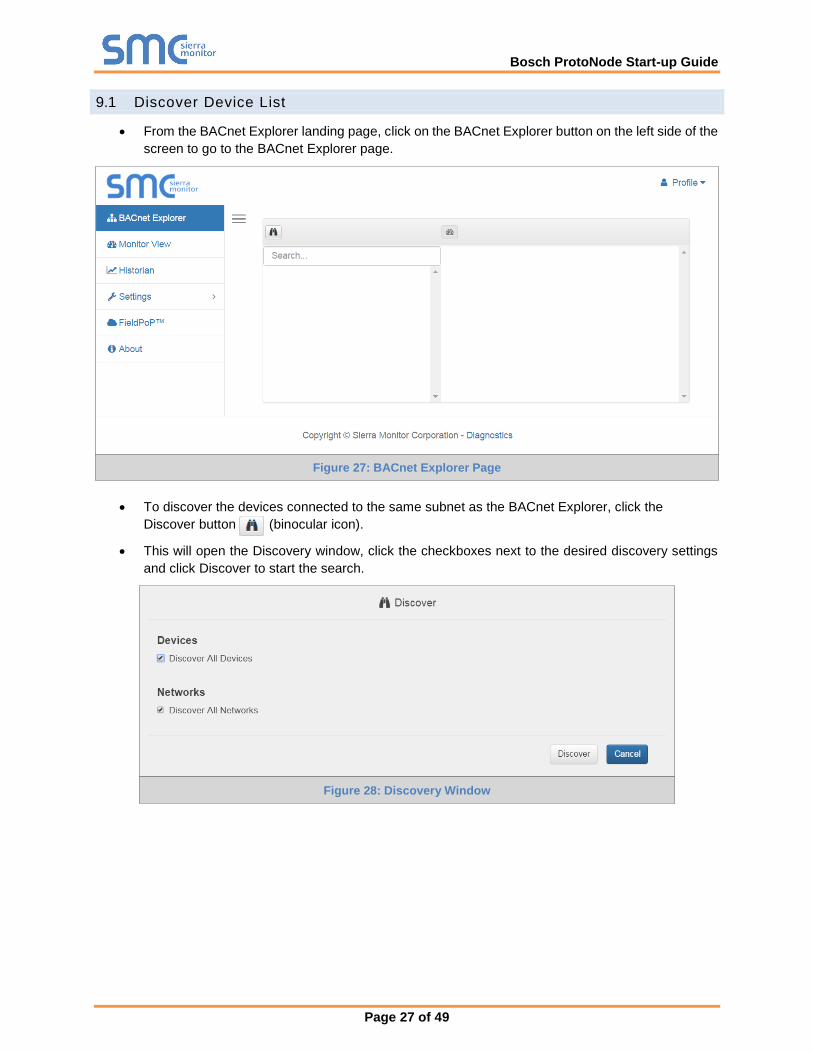
9.1 Discover Device List
• From the BACnet Explorer landing page, click on the BACnet Explorer button on the left side of the
screen to go to the BACnet Explorer page.
• To discover the devices connected to the same subnet as the BACnet Explorer, click the
Discover button (binocular icon).
• This will open the Discovery window, click the checkboxes next to the desired discovery settings
and click Discover to start the search.
Figure 27: BACnet Explorer Page
Figure 28: Discovery Window
Bosch ProtoNode Start-up Guide
Page 28 of 49
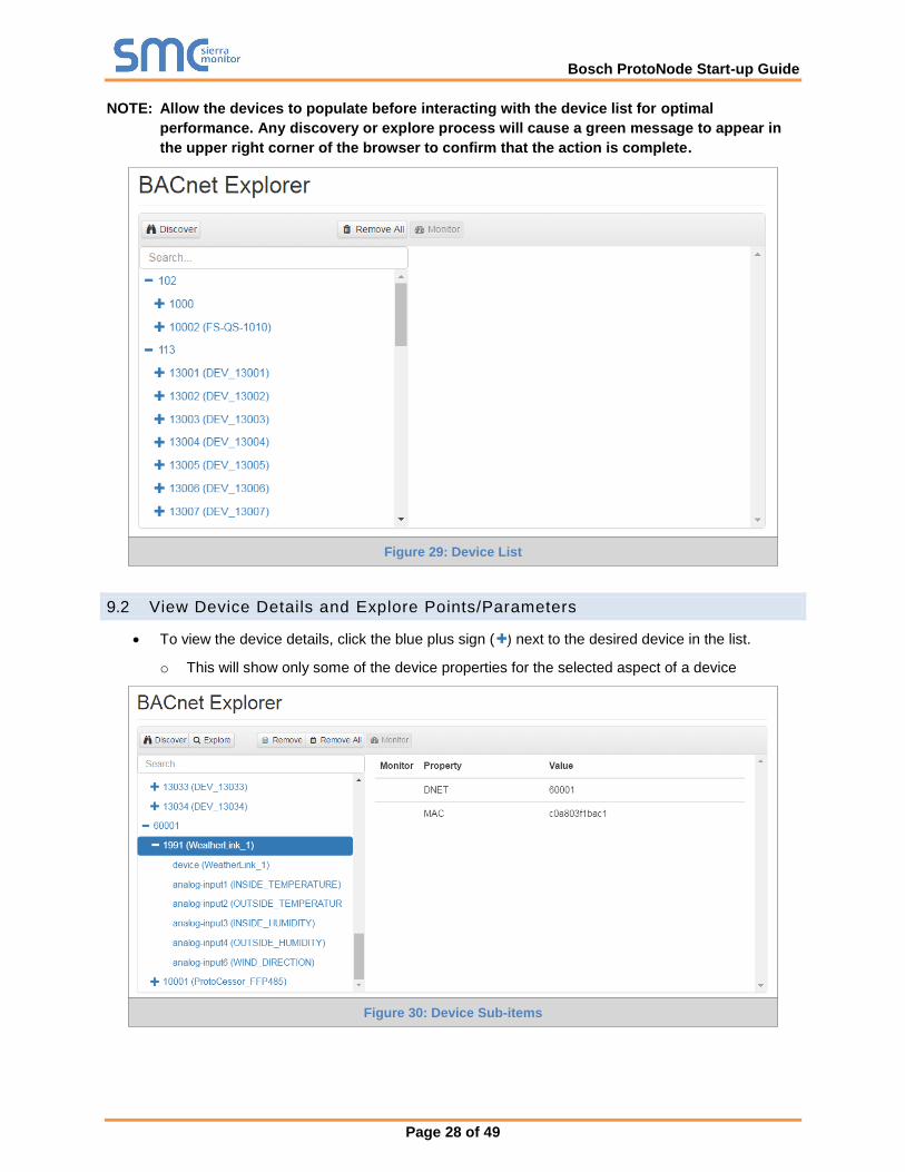
NOTE: Allow the devices to populate before interacting with the device list for optimal
performance. Any discovery or explore process will cause a green message to appear in
the upper right corner of the browser to confirm that the action is complete.
9.2 View Device Details and Explore Points/Parameters
• To view the device details, click the blue plus sign ( ) next to the desired device in the list.
o This will show only some of the device properties for the selected aspect of a device
Figure 29: Device List
Figure 30: Device Sub-items
Bosch ProtoNode Start-up Guide
Page 29 of 49
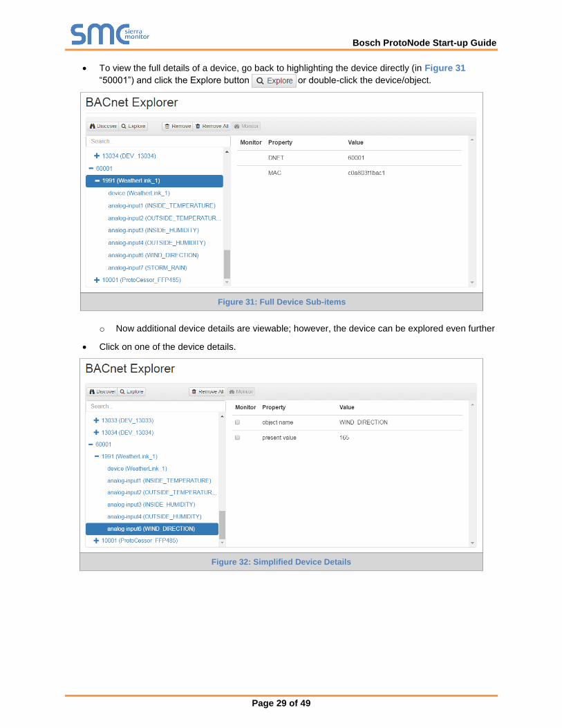
• To view the full details of a device, go back to highlighting the device directly (in Figure 31
“50001”) and click the Explore button or double-click the device/object.
o Now additional device details are viewable; however, the device can be explored even further
• Click on one of the device details.
Figure 31: Full Device Sub-items
Figure 32: Simplified Device Details
Bosch ProtoNode Start-up Guide
Page 30 of 49
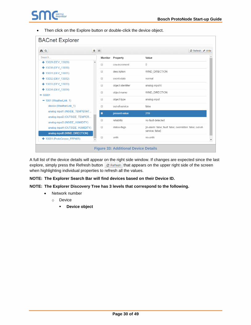
• Then click on the Explore button or double-click the device object.
A full list of the device details will appear on the right side window. If changes are expected since the last
explore, simply press the Refresh button that appears on the upper right side of the screen
when highlighting individual properties to refresh all the values.
NOTE: The Explorer Search Bar will find devices based on their Device ID.
NOTE: The Explorer Discovery Tree has 3 levels that correspond to the following.
• Network number
o Device
▪ Device object
Figure 33: Additional Device Details
Bosch ProtoNode Start-up Guide
Page 31 of 49
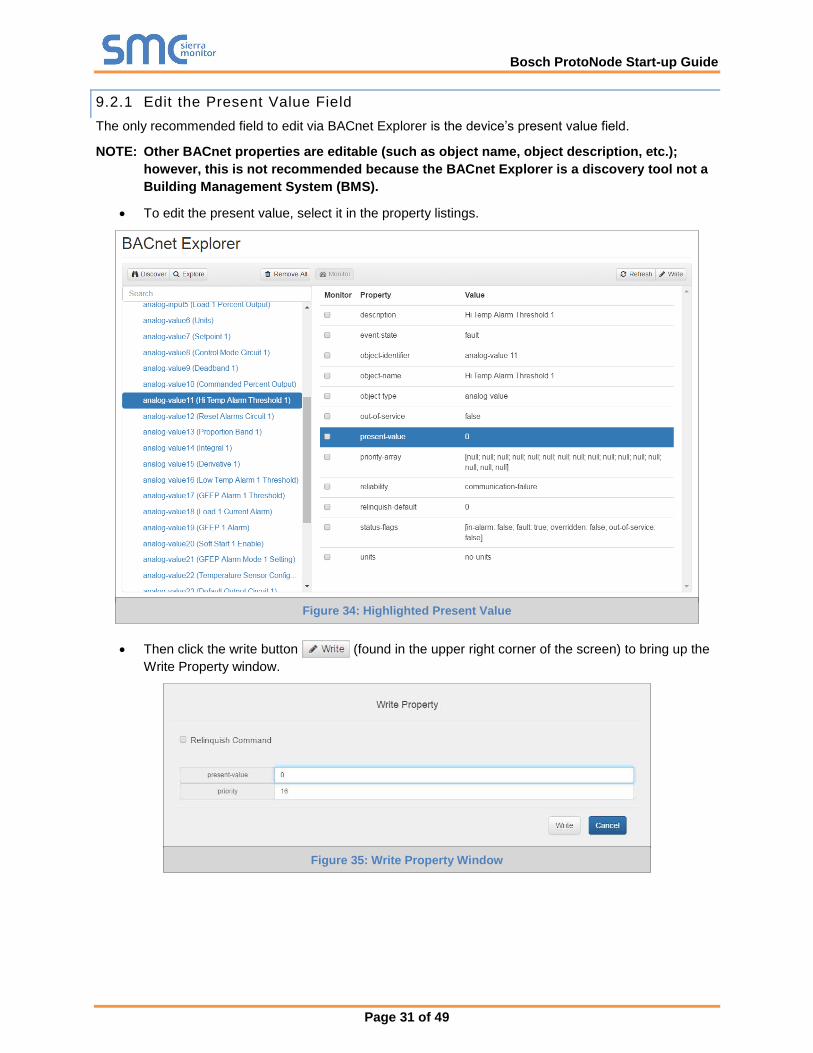
9.2.1 Edit the Present Value Field
The only recommended field to edit via BACnet Explorer is the device’s present value field.
NOTE: Other BACnet properties are editable (such as object name, object description, etc.);
however, this is not recommended because the BACnet Explorer is a discovery tool not a
Building Management System (BMS).
• To edit the present value, select it in the property listings.
• Then click the write button (found in the upper right corner of the screen) to bring up the
Write Property window.
Figure 34: Highlighted Present Value
Figure 35: Write Property Window

Bosch ProtoNode Start-up Guide
Page 32 of 49
• Enter the appropriate change and click write.
A check will appear inside the save button and the window will close. When the BACnet Explorer
page appears the present value will be changed as specified.
Figure 36: Updated Present Value

Bosch ProtoNode Start-up Guide
Page 33 of 49
APPENDIX A TROUBLESHOOTING
Appendix A.1 Lost or Incorrect IP Address
• Ensure that FieldServer Toolbox is loaded onto the local PC. Otherwise, download the
FieldServer-Toolbox.zip via the Sierra Monitor Resource Center Software Downloads.
• Extract the executable file and complete the installation.
• Connect a standard CAT5 Ethernet cable between the user’s PC and ProtoNode.
• Double click on the FS Toolbox Utility and click Discover Now on the splash page.
• Check for the IP Address of the desired gateway.
• If correcting the IP Address of the gateway: click the settings icon on the same row as the
gateway, then click Network Settings, change the IP Address and click Update IP Settings to save.
Ethernet Port
Figure 37: Ethernet Port Location

Bosch ProtoNode Start-up Guide
Page 34 of 49
Appendix A.2 Viewing Diagnostic Information
• Type the IP Address of the ProtoNode into the web browser or use the FieldServer Toolbox to
connect to the ProtoNode.
• Click on Diagnostics and Debugging Button, then click on view, and then on connections.
• If there are any errors showing on the Connection page, refer to Appendix A.3 for the relevant
wiring and settings.
Figure 38: Error Messages Screen

Bosch ProtoNode Start-up Guide
Page 35 of 49
Appendix A.3 Checking Wiring and Settings
• No COMS on Modbus RTU side. If Tx/Rx are not flashing rapidly then there is a COM issue on
the Modbus side. To fix this problem, check the following:
o Visual observations of LEDs on ProtoNode (Appendix A.4)
o Check baud rate, parity, data bits, stop bits
o Check Modbus device address
o Verify wiring
o Verify Modbus device is connected to the same subnet as the ProtoNode
o Verify the Modbus device was discovered in Web Configurator (Section 5.4)
• Field COM problems:
o If Ethernet protocols are used, observe Ethernet LEDs on the ProtoNode (Appendix A.4)
o Check DIP switch settings (using correct baud rate and device instance)
o Verify IP Address setting
o Verify wiring
NOTE: If the problem still exists, a Diagnostic Capture needs to be taken and sent to technical
support. (Appendix A.5)
Bosch ProtoNode Start-up Guide
Page 36 of 49
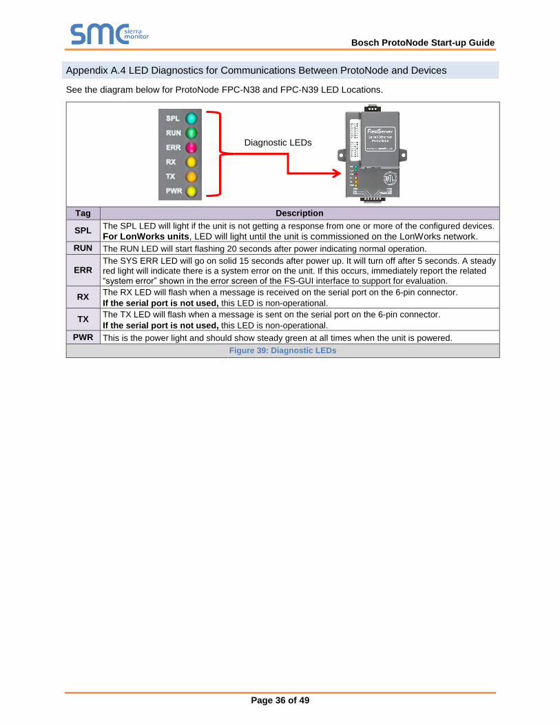
Appendix A.4 LED Diagnostics for Communications Between ProtoNode and Devices
See the diagram below for ProtoNode FPC-N38 and FPC-N39 LED Locations.
Tag Description
SPL The SPL LED will light if the unit is not getting a response from one or more of the configured devices.
For LonWorks units, LED will light until the unit is commissioned on the LonWorks network.
RUN The RUN LED will start flashing 20 seconds after power indicating normal operation.
ERR The SYS ERR LED will go on solid 15 seconds after power up. It will turn off after 5 seconds. A steady red light will indicate there is a system error on the unit. If this occurs, immediately report the related “system error” shown in the error screen of the FS-GUI interface to support for evaluation.
RX The RX LED will flash when a message is received on the serial port on the 6-pin connector.
If the serial port is not used, this LED is non-operational.
TX The TX LED will flash when a message is sent on the serial port on the 6-pin connector.
If the serial port is not used, this LED is non-operational.
PWR This is the power light and should show steady green at all times when the unit is powered.
Figure 39: Diagnostic LEDs
Diagnostic LEDs
Bosch ProtoNode Start-up Guide
Page 37 of 49
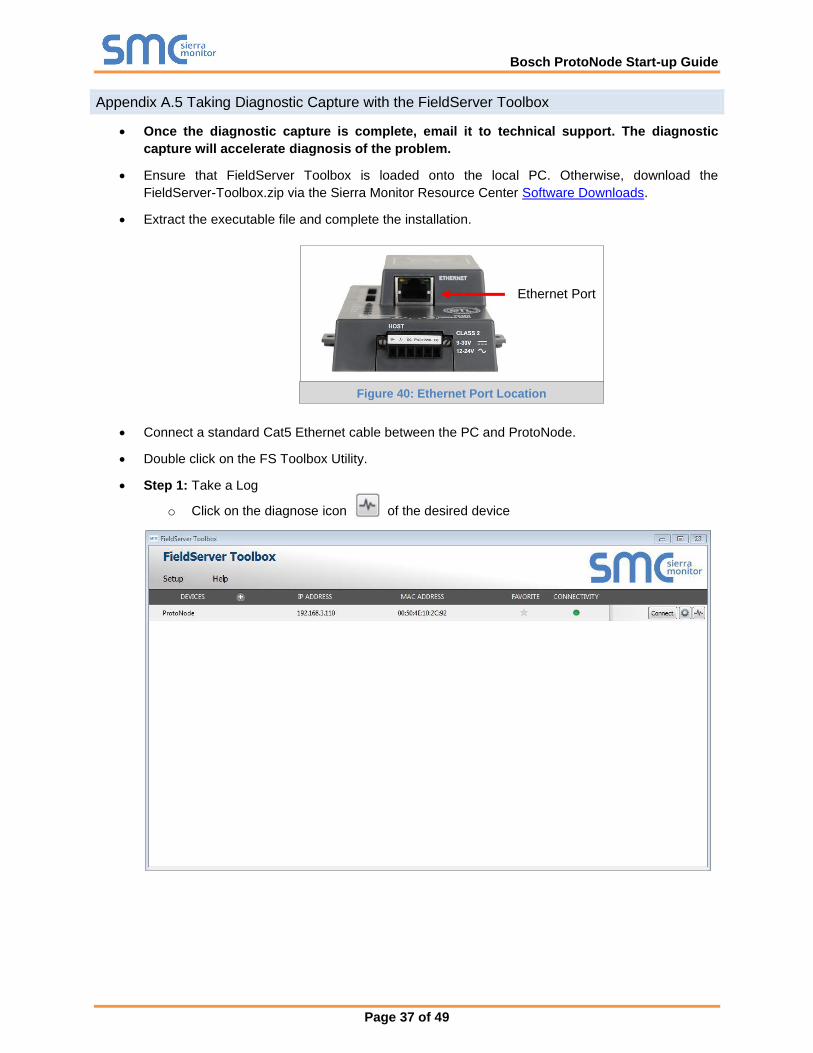
Appendix A.5 Taking Diagnostic Capture with the FieldServer Toolbox
• Once the diagnostic capture is complete, email it to technical support. The diagnostic
capture will accelerate diagnosis of the problem.
• Ensure that FieldServer Toolbox is loaded onto the local PC. Otherwise, download the
FieldServer-Toolbox.zip via the Sierra Monitor Resource Center Software Downloads.
• Extract the executable file and complete the installation.
• Connect a standard Cat5 Ethernet cable between the PC and ProtoNode.
• Double click on the FS Toolbox Utility.
• Step 1: Take a Log
o Click on the diagnose icon of the desired device
Ethernet Port
Figure 40: Ethernet Port Location
Bosch ProtoNode Start-up Guide
Page 38 of 49
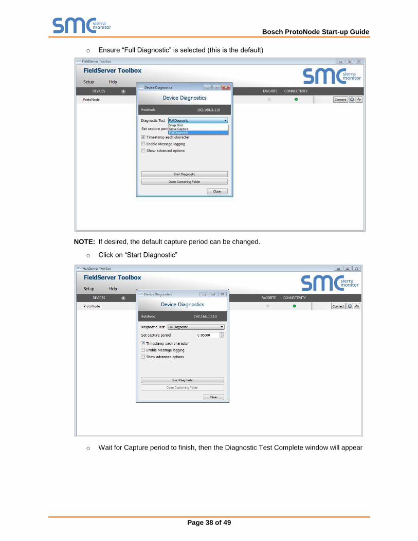
o Ensure “Full Diagnostic” is selected (this is the default)
NOTE: If desired, the default capture period can be changed.
o Click on “Start Diagnostic”
o Wait for Capture period to finish, then the Diagnostic Test Complete window will appear
Bosch ProtoNode Start-up Guide
Page 39 of 49
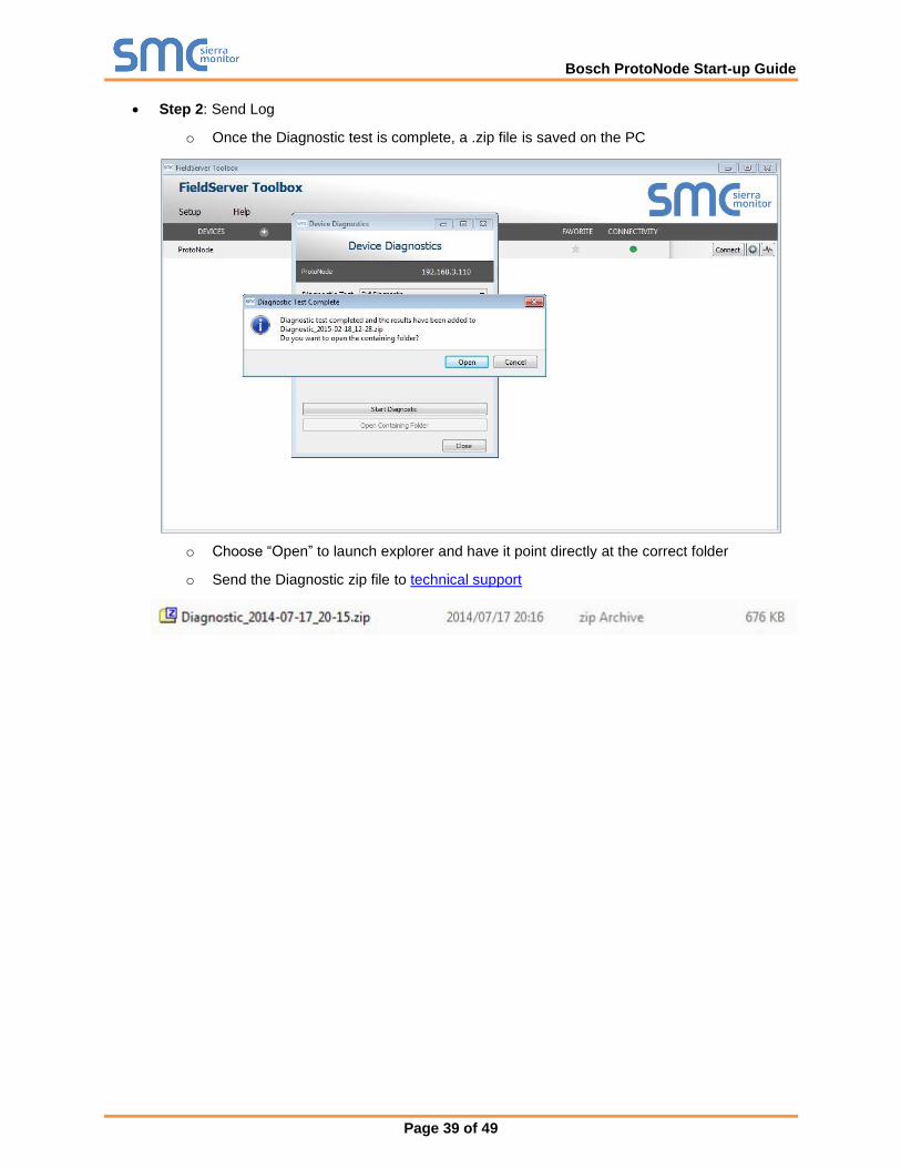
• Step 2: Send Log
o Once the Diagnostic test is complete, a .zip file is saved on the PC
o Choose “Open” to launch explorer and have it point directly at the correct folder
o Send the Diagnostic zip file to technical support

Bosch ProtoNode Start-up Guide
Page 40 of 49
Appendix A.6 Updating Firmware
To load a new version of the firmware, follow these instructions:
1. Extract and save the new file onto the local PC.
2. Open a web browser and type the IP Address of the FieldServer in the address bar.
o Default IP Address is 192.168.1.24
o Use the FS Toolbox utility if the IP Address is unknown (Appendix A.1)
3. Click on the “Diagnostics & Debugging” button.
4. In the Navigation Tree on the left hand side, do the following:
a. Click on “Setup”
b. Click on “File Transfer”
c. Click on the “General” tab
5. In the General tab, click on “Choose Files” and select the web.img file extracted in step 1.
6. Click on the orange “Submit” button.
7. When the download is complete, click on the “System Restart” button.
Appendix A.7 BACnet: Setting Network_Number for More Than one ProtoNode on the Subnet
For both BACnet MS/TP and BACnet/IP, if more than one ProtoNode is connected to the same subnet,
they must be assigned unique Network_Number values.
On the main Web Configuration screen, update the BACnet Network Number field and click submit. The
default value is 50001.
Figure 41: Web Configurator – Network Number Field

Bosch ProtoNode Start-up Guide
Page 41 of 49
Appendix A.8 Securing ProtoNode with Passwords
Access to the ProtoNode can be restricted by enabling a password on the FS-GUI Passwords page –
click Setup and then Passwords in the navigation panel. There are 2 access levels defined by 2 account
names: Admin and User.
• The Admin account has unrestricted access to the ProtoNode.
• The User account can view any ProtoNode information, but cannot make any changes or restart
the ProtoNode.
The password needs to be a minimum of eight characters and is case sensitive.
If the password is lost, click cancel on the password authentication popup window, and email the password
recovery token to technical support to receive a temporary password from the customer support team.
Access the ProtoNode to set a new password.
Figure 42: FS-GUI Passwords Page
Figure 43: Password Recovery Page

Bosch ProtoNode Start-up Guide
Page 42 of 49
APPENDIX B VENDOR INFORMATION – BOSCH
NOTE: All Modbus TCP/IP registers are the same as the Modbus RTU registers for the serial device. If
this point list is needed, contact Bosch technical support. The Modbus TCP/IP node address of the
device is also the same as the Modbus RTU node address.
Appendix B.1 D_Platform Modbus RTU Mappings to BACnet, Metasys N2 and LonWorks
Point Name BACnet Object Type
BACnet Object ID
N2 Data Type
N2 Address
LonWorks Name LonWorks SNVT
Reset Curve Boiler Design AV 1 AO 1 nvi/nvoResCvBlDs_XXX SNVT_temp_p
Reset Curve Boiler Mild Weather AV 2 AO 2 nvi/nvoResCvBMWt_XXX SNVT_temp_p
Reset Curve Outdoor Mild Weather AV 3 AO 3 nvi/nvoResCvOMWt_XXX SNVT_temp_p
Reset Curve Outdoor Design AV 4 AO 4 nvi/nvoResCvOtDs_XXX SNVT_temp_p
Warm Weather Shutdown AV 5 AO 5 nvi/nvoWmWthShDn_XXX SNVT_temp_p
Reset Curve Boiler Maximum AV 6 AO 6 nvi/nvoResCvBlMx_XXX SNVT_temp_p
Reset Curve Boiler Minimum AV 7 AO 7 nvi/nvoResCvBlMn_XXX SNVT_temp_p
Night Setback AV 8 AO 8 nvi/nvoNtStbk_XXX SNVT_temp_p
Power Level For Entire System AI 9 AI 9 nvoPwrLvl_XXX SNVT_lev_percent
Cascade Ch Mode X SP AV 10 AO 10 nvi/nvoCscChMdSP_XXX SNVT_temp_p
System Supply SP AI 11 AI 11 nvoSysSupSP_XXX SNVT_temp_p
System Supply Sensor Temp AI 12 AI 12 nvoSysSpSnTp_XXX SNVT_temp_p
Outdoor Sensor Temp AI 13 AI 13 nvoOutSenTmp_XXX SNVT_temp_p
Cascade Pump Status BI 14 DI 14 nvoCscPmpSt_XXX SNVT_switch
Boiler 1 Available / Present BI 15 DI 15 nvoB1Avail_XXX SNVT_switch
Boiler 2 Available / Present BI 16 DI 16 nvoB2Avail_XXX SNVT_switch
Boiler 3 Available / Present BI 17 DI 17 nvoB3Avail_XXX SNVT_switch
Boiler 4 Available / Present BI 18 DI 18 nvoB4Avail_XXX SNVT_switch
Boiler 1 Is Active / Heating BI 19 DI 19 nvoB1ActHt_XXX SNVT_switch
Boiler 2 Is Active / Heating BI 20 DI 20 nvoB2ActHt_XXX SNVT_switch
Boiler 3 Is Active / Heating BI 21 DI 21 nvoB3ActHt_XXX SNVT_switch
Boiler 4 Is Active / Heating BI 22 DI 22 nvoB4ActHt_XXX SNVT_switch
Boiler 1 Has Error BI 23 DI 23 nvoB1Err_XXX SNVT_switch
Boiler 2 Has Error BI 24 DI 24 nvoB2Err_XXX SNVT_switch
Boiler 3 Has Error BI 25 DI 25 nvoB3Err_XXX SNVT_switch
Boiler 4 Has Error BI 26 DI 26 nvoB4Err_XXX SNVT_switch
Boiler 1 Requires Service BI 27 DI 27 nvoB1ReqSvc_XXX SNVT_switch
Boiler 2 Requires Service BI 28 DI 28 nvoB2ReqSvc_XXX SNVT_switch
Boiler 3 Requires Service BI 29 DI 29 nvoB3ReqSvc_XXX SNVT_switch
Boiler 4 Requires Service BI 30 DI 30 nvoB4ReqSvc_XXX SNVT_switch
Boiler Address AV 31 AO 31 nvi/nvoBlrAddr_XXX SNVT_count_f
Power Level For The Boiler AI 32 AI 32 nvoBlrPwrLvl_XXX SNVT_lev_percent
Boiler Supply SP AI 33 AI 33 nvoBlrSupSP_XXX SNVT_temp_p
Heat Demand Type AI 34 AI 34 nvoHtDemTyp_XXX SNVT_count_f
System Sensor Temp AI 35 AI 35 nvoSysSenTmp_XXX SNVT_temp_p
Dhw Temp AI 36 AI 36 nvoDhwTemp_XXX SNVT_temp_p
Ch Pump Running BI 37 DI 37 nvoChPPmpRun_XXX SNVT_switch
Dhw Pump Status BI 38 DI 38 nvoDhwPmpSt_XXX SNVT_switch
Total Burn Hours AI 39 AI 39 nvoTotBrnHr_XXX SNVT_time_hour
Blr 1 - Burner 1 Available/Present BI 40 DI 40 nvo1B1Avail_XXX SNVT_switch
Blr 1 - Burner 2 Available/Present BI 41 DI 41 nvo1B2Avail_XXX SNVT_switch
Blr 2 - Burner 1 Available/Present BI 42 DI 42 nvo2B1Avail_XXX SNVT_switch
Blr 2 - Burner 2 Available/Present BI 43 DI 43 nvo2B2Avail_XXX SNVT_switch
Blr 3 - Burner 1 Available/Present BI 44 DI 44 nvo3B1Avail_XXX SNVT_switch
Blr 3 - Burner 2 Available/Present BI 45 DI 45 nvo3B2Avail_XXX SNVT_switch
Blr 4 - Burner 1 Available/Present BI 46 DI 46 nvo4B1Avail_XXX SNVT_switch
Blr 4 - Burner 2 Available/Present BI 47 DI 47 nvo4B2Avail_XXX SNVT_switch
Blr 1 - Burner 1 Current State AI 48 AI 48 nvo1B1CurSt_XXX SNVT_count_f
Blr 1 - Burner 1 Error AI 49 AI 49 nvo1B1Err_XXX SNVT_count_f
Blr 1 - Burner 1 Supply SP AI 50 AI 50 nvo1B1SupSP_XXX SNVT_temp_p
Blr 1 - Burner 1 Power Level AI 51 AI 51 nvo1B1PwrLvl_XXX SNVT_lev_percent
Blr 1 - Burner 1 Gen Pump Status BI 52 DI 52 nvo1B1GnPmSt_XXX SNVT_switch

Bosch ProtoNode Start-up Guide
Page 43 of 49
Blr 1 - Burner 1 CH Flow Rate AI 53 AI 53 nvo1B1ChFlRt_XXX SNVT_count_f
Blr 1 - Burner 1 Actual Fan Speed AI 54 AI 54 nvo1B1AcFnSp_XXX SNVT_count_f
Blr 1 - Burner 1 Supply Sensor Temp AI 55 AI 55 nvo1B1SpSnTp_XXX SNVT_temp_p
Blr 1 - Burner 1 Return Sensor Temp AI 56 AI 56 nvo1B1RtSnTp_XXX SNVT_temp_p
Blr 1 - Burner 1 Flue Sensor Temp AI 57 AI 57 nvo1B1FlSnTp_XXX SNVT_temp_p
Blr 1 - Burner 1 Total Burn Hours AI 58 AI 58 nvo1B1ToBnHr_XXX SNVT_time_hour
Blr 1 - Burner 2 Current State AI 59 AI 59 nvo1B2CurSt_XXX SNVT_count_f
Blr 1 - Burner 2 Error AI 60 AI 60 nvo1B2Err_XXX SNVT_count_f
Blr 1 - Burner 2 Supply SP AI 61 AI 61 nvo1B2SupSP_XXX SNVT_temp_p
Blr 1 - Burner 2 Power Level AI 62 AI 62 nvo1B2PwrLvl_XXX SNVT_lev_percent
Blr 1 - Burner 2 Gen Pump Status BI 63 DI 63 nvo1B2GnPmSt_XXX SNVT_switch
Blr 1 - Burner 2 CH Flow Rate AI 64 AI 64 nvo1B2ChFlRt_XXX SNVT_count_f
Blr 1 - Burner 2 Actual Fan Speed AI 65 AI 65 nvo1B2AcFnSp_XXX SNVT_count_f
Blr 1 - Burner 2 Supply Sensor Temp AI 66 AI 66 nvo1B2SpSnTp_XXX SNVT_temp_p
Blr 1 - Burner 2 Return Sensor Temp AI 67 AI 67 nvo1B2RtSnTp_XXX SNVT_temp_p
Blr 1 - Burner 2 Flue Sensor Temp AI 68 AI 68 nvo1B2FlSnTp_XXX SNVT_temp_p
Blr 1 - Burner 2 Total Burn Hours AI 69 AI 69 nvo1B2ToBnHr_XXX SNVT_time_hour
Blr 2 - Burner 1 Current State AI 70 AI 70 nvo2B1CurSt_XXX SNVT_count_f
Blr 2 - Burner 1 Error AI 71 AI 71 nvo2B1Err_XXX SNVT_count_f
Blr 2 - Burner 1 Supply SP AI 72 AI 72 nvo2B1SupSP_XXX SNVT_temp_p
Blr 2 - Burner 1 Power Level AI 73 AI 73 nvo2B1PwrLvl_XXX SNVT_lev_percent
Blr 2 - Burner 1 Gen Pump Status BI 74 DI 74 nvo2B1GnPmSt_XXX SNVT_switch
Blr 2 - Burner 1 CH Flow Rate AI 75 AI 75 nvo2B1ChFlRt_XXX SNVT_count_f
Blr 2 - Burner 1 Actual Fan Speed AI 76 AI 76 nvo2B1AcFnSp_XXX SNVT_count_f
Blr 2 - Burner 1 Supply Sensor Temp AI 77 AI 77 nvo2B1SpSnTp_XXX SNVT_temp_p
Blr 2 - Burner 1 Return Sensor Temp AI 78 AI 78 nvo2B1RtSnTp_XXX SNVT_temp_p
Blr 2 - Burner 1 Flue Sensor Temp AI 79 AI 79 nvo2B1FlSnTp_XXX SNVT_temp_p
Blr 2 - Burner 1 Total Burn Hours AI 80 AI 80 nvo2B1ToBnHr_XXX SNVT_time_hour
Blr 2 - Burner 2 Current State AI 81 AI 81 nvo2B2CurSt_XXX SNVT_count_f
Blr 2 - Burner 2 Error AI 82 AI 82 nvo2B2Err_XXX SNVT_count_f
Blr 2 - Burner 2 Supply SP AI 83 AI 83 nvo2B2SupSP_XXX SNVT_temp_p
Blr 2 - Burner 2 Power Level AI 84 AI 84 nvo2B2PwrLvl_XXX SNVT_lev_percent
Blr 2 - Burner 2 Gen Pump Status BI 85 DI 85 nvo2B2GnPmSt_XXX SNVT_switch
Blr 2 - Burner 2 CH Flow Rate AI 86 AI 86 nvo2B2ChFlRt_XXX SNVT_count_f
Blr 2 - Burner 2 Actual Fan Speed AI 87 AI 87 nvo2B2AcFnSp_XXX SNVT_count_f
Blr 2 - Burner 2 Supply Sensor Temp AI 88 AI 88 nvo2B2SpSnTp_XXX SNVT_temp_p
Blr 2 - Burner 2 Return Sensor Temp AI 89 AI 89 nvo2B2RtSnTp_XXX SNVT_temp_p
Blr 2 - Burner 2 Flue Sensor Temp AI 90 AI 90 nvo2B2FlSnTp_XXX SNVT_temp_p
Blr 2 - Burner 2 Total Burn Hours AI 91 AI 91 nvo2B2ToBnHr_XXX SNVT_time_hour
Blr 3 - Burner 1 Current State AI 92 AI 92 nvo3B1CurSt_XXX SNVT_count_f
Blr 3 - Burner 1 Error AI 93 AI 93 nvo3B1Err_XXX SNVT_count_f
Blr 3 - Burner 1 Supply SP AI 94 AI 94 nvo3B1SupSP_XXX SNVT_temp_p
Blr 3 - Burner 1 Power Level AI 95 AI 95 nvo3B1PwrLvl_XXX SNVT_lev_percent
Blr 3 - Burner 1 Gen Pump Status BI 96 DI 96 nvo3B1GnPmSt_XXX SNVT_switch
Blr 3 - Burner 1 CH Flow Rate AI 97 AI 97 nvo3B1ChFlRt_XXX SNVT_count_f
Blr 3 - Burner 1 Actual Fan Speed AI 98 AI 98 nvo3B1AcFnSp_XXX SNVT_count_f
Blr 3 - Burner 1 Supply Sensor Temp AI 99 AI 99 nvo3B1SpSnTp_XXX SNVT_temp_p
Blr 3 - Burner 1 Return Sensor Temp AI 100 AI 100 nvo3B1RtSnTp_XXX SNVT_temp_p
Blr 3 - Burner 1 Flue Sensor Temp AI 101 AI 101 nvo3B1FlSnTp_XXX SNVT_temp_p
Blr 3 - Burner 1 Total Burn Hours AI 102 AI 102 nvo3B1ToBnHr_XXX SNVT_time_hour
Blr 3 - Burner 2 Current State AI 103 AI 103 nvo3B2CurSt_XXX SNVT_count_f
Blr 3 - Burner 2 Error AI 104 AI 104 nvo3B2Err_XXX SNVT_count_f
Blr 3 - Burner 2 Supply SP AI 105 AI 105 nvo3B2SupSP_XXX SNVT_temp_p
Blr 3 - Burner 2 Power Level AI 106 AI 106 nvo3B2PwrLvl_XXX SNVT_lev_percent
Blr 3 - Burner 2 Gen Pump Status BI 107 DI 107 nvo3B2GnPmSt_XXX SNVT_switch
Blr 3 - Burner 2 CH Flow Rate AI 108 AI 108 nvo3B2ChFlRt_XXX SNVT_count_f
Blr 3 - Burner 2 Actual Fan Speed AI 109 AI 109 nvo3B2AcFnSp_XXX SNVT_count_f
Blr 3 - Burner 2 Supply Sensor Temp AI 110 AI 110 nvo3B2SpSnTp_XXX SNVT_temp_p
Blr 3 - Burner 2 Return Sensor Temp AI 111 AI 111 nvo3B2RtSnTp_XXX SNVT_temp_p
Blr 3 - Burner 2 Flue Sensor Temp AI 112 AI 112 nvo3B2FlSnTp_XXX SNVT_temp_p
Blr 3 - Burner 2 Total Burn Hours AI 113 AI 113 nvo3B2ToBnHr_XXX SNVT_time_hour
Blr 4 - Burner 1 Current State AI 114 AI 114 nvo4B1CurSt_XXX SNVT_count_f
Blr 4 - Burner 1 Error AI 115 AI 115 nvo4B1Err_XXX SNVT_count_f
Blr 4 - Burner 1 Supply SP AI 116 AI 116 nvo4B1SupSP_XXX SNVT_temp_p

Bosch ProtoNode Start-up Guide
Page 44 of 49
Blr 4 - Burner 1 Power Level AI 117 AI 117 nvo4B1PwrLvl_XXX SNVT_lev_percent
Blr 4 - Burner 1 Gen Pump Status BI 118 DI 118 nvo4B1GnPmSt_XXX SNVT_switch
Blr 4 - Burner 1 CH Flow Rate AI 119 AI 119 nvo4B1ChFlRt_XXX SNVT_count_f
Blr 4 - Burner 1 Actual Fan Speed AI 120 AI 120 nvo4B1AcFnSp_XXX SNVT_count_f
Blr 4 - Burner 1 Supply Sensor Temp AI 121 AI 121 nvo4B1SpSnTp_XXX SNVT_temp_p
Blr 4 - Burner 1 Return Sensor Temp AI 122 AI 122 nvo4B1RtSnTp_XXX SNVT_temp_p
Blr 4 - Burner 1 Flue Sensor Temp AI 123 AI 123 nvo4B1FlSnTp_XXX SNVT_temp_p
Blr 4 - Burner 1 Total Burn Hours AI 124 AI 124 nvo4B1ToBnHr_XXX SNVT_time_hour
Blr 4 - Burner 2 Current State AI 125 AI 125 nvo4B2CurSt_XXX SNVT_count_f
Blr 4 - Burner 2 Error AI 126 AI 126 nvo4B2Err_XXX SNVT_count_f
Blr 4 - Burner 2 Supply SP AI 127 AI 127 nvo4B2SupSP_XXX SNVT_temp_p
Blr 4 - Burner 2 Power Level AI 128 AI 128 nvo4B2PwrLvl_XXX SNVT_lev_percent
Blr 4 - Burner 2 Gen Pump Status BI 129 DI 129 nvo4B2GnPmSt_XXX SNVT_switch
Blr 4 - Burner 2 CH Flow Rate AI 130 AI 130 nvo4B2ChFlRt_XXX SNVT_count_f
Blr 4 - Burner 2 Actual Fan Speed AI 131 AI 131 nvo4B2AcFnSp_XXX SNVT_count_f
Blr 4 - Burner 2 Supply Sensor Temp AI 132 AI 132 nvo4B2SpSnTp_XXX SNVT_temp_p
Blr 4 - Burner 2 Return Sensor Temp AI 133 AI 133 nvo4B2RtSnTp_XXX SNVT_temp_p
Blr 4 - Burner 2 Flue Sensor Temp AI 134 AI 134 nvo4B2FlSnTp_XXX SNVT_temp_p
Blr 4 - Burner 2 Total Burn Hours AI 135 AI 135 nvo4B2ToBnHr_XXX SNVT_time_hour
Error Number AI 136 AI 136 nvoErrNum_XXX SNVT_count_f
Boiler ID AI 137 AI 137 nvoBlrID_XXX SNVT_count_f
Timestamp: Day Of Week AI 138 AI 138 nvoTmDayOfWk_XXX SNVT_count_f
Timestamp: Day Of Month AI 139 AI 139 nvoTmDayOfMt_XXX SNVT_count_f
Timestamp: Month AI 140 AI 140 nvoTmMonth_XXX SNVT_count_f
Timestamp: Year AI 141 AI 141 nvoTmYear_XXX SNVT_count_f
Timestamp: Hour AI 142 AI 142 nvoTmHour_XXX SNVT_count_f
Timestamp: Minute AI 143 AI 143 nvoTmMinute_XXX SNVT_count_f
Burn Hours Since Last Service AI 144 AI 144 nvoTmSncLtSv_XXX SNVT_time_hour
Burn Hours Till Service Is Required AI 145 AI 145 nvoBrHrSvc_XXX SNVT_count_f
Overdue Counter 0 AI 146 AI 146 nvoOvrduCnt0_XXX SNVT_time_hour
Service Interval AI 147 AI 147 nvoSrvcInt_XXX SNVT_time_hour
Bosch ProtoNode Start-up Guide
Page 45 of 49
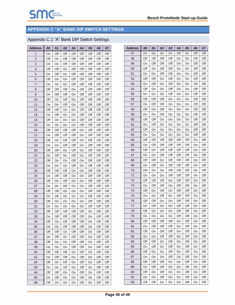
APPENDIX C “A” BANK DIP SWITCH SETTINGS
Appendix C.1 “A” Bank DIP Switch Settings
Address A0 A1 A2 A3 A4 A5 A6 A7
1 On Off Off Off Off Off Off Off
2 Off On Off Off Off Off Off Off
3 On On Off Off Off Off Off Off
4 Off Off On Off Off Off Off Off
5 On Off On Off Off Off Off Off
6 Off On On Off Off Off Off Off
7 On On On Off Off Off Off Off
8 Off Off Off On Off Off Off Off
9 On Off Off On Off Off Off Off
10 Off On Off On Off Off Off Off
11 On On Off On Off Off Off Off
12 Off Off On On Off Off Off Off
13 On Off On On Off Off Off Off
14 Off On On On Off Off Off Off
15 On On On On Off Off Off Off
16 Off Off Off Off On Off Off Off
17 On Off Off Off On Off Off Off
18 Off On Off Off On Off Off Off
19 On On Off Off On Off Off Off
20 Off Off On Off On Off Off Off
21 On Off On Off On Off Off Off
22 Off On On Off On Off Off Off
23 On On On Off On Off Off Off
24 Off Off Off On On Off Off Off
25 On Off Off On On Off Off Off
26 Off On Off On On Off Off Off
27 On On Off On On Off Off Off
28 Off Off On On On Off Off Off
29 On Off On On On Off Off Off
30 Off On On On On Off Off Off
31 On On On On On Off Off Off
32 Off Off Off Off Off On Off Off
33 On Off Off Off Off On Off Off
34 Off On Off Off Off On Off Off
35 On On Off Off Off On Off Off
36 Off Off On Off Off On Off Off
37 On Off On Off Off On Off Off
38 Off On On Off Off On Off Off
39 On On On Off Off On Off Off
40 Off Off Off On Off On Off Off
41 On Off Off On Off On Off Off
42 Off On Off On Off On Off Off
43 On On Off On Off On Off Off
44 Off Off On On Off On Off Off
45 On Off On On Off On Off Off
46 Off On On On Off On Off Off
Address A0 A1 A2 A3 A4 A5 A6 A7
47 On On On On Off On Off Off
48 Off Off Off Off On On Off Off
49 On Off Off Off On On Off Off
50 Off On Off Off On On Off Off
51 On On Off Off On On Off Off
52 Off Off On Off On On Off Off
53 On Off On Off On On Off Off
54 Off On On Off On On Off Off
55 On On On Off On On Off Off
56 Off Off Off On On On Off Off
57 On Off Off On On On Off Off
58 Off On Off On On On Off Off
59 On On Off On On On Off Off
60 Off Off On On On On Off Off
61 On Off On On On On Off Off
62 Off On On On On On Off Off
63 On On On On On On Off Off
64 Off Off Off Off Off Off On Off
65 On Off Off Off Off Off On Off
66 Off On Off Off Off Off On Off
67 On On Off Off Off Off On Off
68 Off Off On Off Off Off On Off
69 On Off On Off Off Off On Off
70 Off On On Off Off Off On Off
71 On On On Off Off Off On Off
72 Off Off Off On Off Off On Off
73 On Off Off On Off Off On Off
74 Off On Off On Off Off On Off
75 On On Off On Off Off On Off
76 Off Off On On Off Off On Off
77 On Off On On Off Off On Off
78 Off On On On Off Off On Off
79 On On On On Off Off On Off
80 Off Off Off Off On Off On Off
81 On Off Off Off On Off On Off
82 Off On Off Off On Off On Off
83 On On Off Off On Off On Off
84 Off Off On Off On Off On Off
85 On Off On Off On Off On Off
86 Off On On Off On Off On Off
87 On On On Off On Off On Off
88 Off Off Off On On Off On Off
89 On Off Off On On Off On Off
90 Off On Off On On Off On Off
91 On On Off On On Off On Off
92 Off Off On On On Off On Off

Bosch ProtoNode Start-up Guide
Page 46 of 49
Address A0 A1 A2 A3 A4 A5 A6 A7
93 On Off On On On Off On Off
94 Off On On On On Off On Off
95 On On On On On Off On Off
96 Off Off Off Off Off On On Off
97 On Off Off Off Off On On Off
98 Off On Off Off Off On On Off
99 On On Off Off Off On On Off
100 Off Off On Off Off On On Off
101 On Off On Off Off On On Off
102 Off On On Off Off On On Off
103 On On On Off Off On On Off
104 Off Off Off On Off On On Off
105 On Off Off On Off On On Off
106 Off On Off On Off On On Off
107 On On Off On Off On On Off
108 Off Off On On Off On On Off
109 On Off On On Off On On Off
110 Off On On On Off On On Off
111 On On On On Off On On Off
112 Off Off Off Off On On On Off
113 On Off Off Off On On On Off
114 Off On Off Off On On On Off
115 On On Off Off On On On Off
116 Off Off On Off On On On Off
117 On Off On Off On On On Off
118 Off On On Off On On On Off
119 On On On Off On On On Off
120 Off Off Off On On On On Off
121 On Off Off On On On On Off
122 Off On Off On On On On Off
123 On On Off On On On On Off
124 Off Off On On On On On Off
125 On Off On On On On On Off
126 Off On On On On On On Off
127 On On On On On On On Off
128 Off Off Off Off Off Off Off On
129 On Off Off Off Off Off Off On
130 Off On Off Off Off Off Off On
131 On On Off Off Off Off Off On
132 Off Off On Off Off Off Off On
133 On Off On Off Off Off Off On
134 Off On On Off Off Off Off On
135 On On On Off Off Off Off On
136 Off Off Off On Off Off Off On
137 On Off Off On Off Off Off On
138 Off On Off On Off Off Off On
139 On On Off On Off Off Off On
140 Off Off On On Off Off Off On
141 On Off On On Off Off Off On
142 Off On On On Off Off Off On
Address A0 A1 A2 A3 A4 A5 A6 A7
143 On On On On Off Off Off On
144 Off Off Off Off On Off Off On
145 On Off Off Off On Off Off On
146 Off On Off Off On Off Off On
147 On On Off Off On Off Off On
148 Off Off On Off On Off Off On
149 On Off On Off On Off Off On
150 Off On On Off On Off Off On
151 On On On Off On Off Off On
152 Off Off Off On On Off Off On
153 On Off Off On On Off Off On
154 Off On Off On On Off Off On
155 On On Off On On Off Off On
156 Off Off On On On Off Off On
157 On Off On On On Off Off On
158 Off On On On On Off Off On
159 On On On On On Off Off On
160 Off Off Off Off Off On Off On
161 On Off Off Off Off On Off On
162 Off On Off Off Off On Off On
163 On On Off Off Off On Off On
164 Off Off On Off Off On Off On
165 On Off On Off Off On Off On
166 Off On On Off Off On Off On
167 On On On Off Off On Off On
168 Off Off Off On Off On Off On
169 On Off Off On Off On Off On
170 Off On Off On Off On Off On
171 On On Off On Off On Off On
172 Off Off On On Off On Off On
173 On Off On On Off On Off On
174 Off On On On Off On Off On
175 On On On On Off On Off On
176 Off Off Off Off On On Off On
177 On Off Off Off On On Off On
178 Off On Off Off On On Off On
179 On On Off Off On On Off On
180 Off Off On Off On On Off On
181 On Off On Off On On Off On
182 Off On On Off On On Off On
183 On On On Off On On Off On
184 Off Off Off On On On Off On
185 On Off Off On On On Off On
186 Off On Off On On On Off On
187 On On Off On On On Off On
188 Off Off On On On On Off On
189 On Off On On On On Off On
190 Off On On On On On Off On
191 On On On On On On Off On
192 Off Off Off Off Off Off On On

Bosch ProtoNode Start-up Guide
Page 47 of 49
Address A0 A1 A2 A3 A4 A5 A6 A7
193 On Off Off Off Off Off On On
194 Off On Off Off Off Off On On
195 On On Off Off Off Off On On
196 Off Off On Off Off Off On On
197 On Off On Off Off Off On On
198 Off On On Off Off Off On On
199 On On On Off Off Off On On
200 Off Off Off On Off Off On On
201 On Off Off On Off Off On On
202 Off On Off On Off Off On On
203 On On Off On Off Off On On
204 Off Off On On Off Off On On
205 On Off On On Off Off On On
206 Off On On On Off Off On On
207 On On On On Off Off On On
208 Off Off Off Off On Off On On
209 On Off Off Off On Off On On
210 Off On Off Off On Off On On
211 On On Off Off On Off On On
212 Off Off On Off On Off On On
213 On Off On Off On Off On On
214 Off On On Off On Off On On
215 On On On Off On Off On On
216 Off Off Off On On Off On On
217 On Off Off On On Off On On
218 Off On Off On On Off On On
219 On On Off On On Off On On
220 Off Off On On On Off On On
221 On Off On On On Off On On
222 Off On On On On Off On On
223 On On On On On Off On On
224 Off Off Off Off Off On On On
225 On Off Off Off Off On On On
226 Off On Off Off Off On On On
227 On On Off Off Off On On On
228 Off Off On Off Off On On On
229 On Off On Off Off On On On
230 Off On On Off Off On On On
231 On On On Off Off On On On
232 Off Off Off On Off On On On
233 On Off Off On Off On On On
234 Off On Off On Off On On On
235 On On Off On Off On On On
236 Off Off On On Off On On On
237 On Off On On Off On On On
238 Off On On On Off On On On
239 On On On On Off On On On
240 Off Off Off Off On On On On
241 On Off Off Off On On On On
242 Off On Off Off On On On On
Address A0 A1 A2 A3 A4 A5 A6 A7
243 On On Off Off On On On On
244 Off Off On Off On On On On
245 On Off On Off On On On On
246 Off On On Off On On On On
247 On On On Off On On On On
248 Off Off Off On On On On On
249 On Off Off On On On On On
250 Off On Off On On On On On
251 On On Off On On On On On
252 Off Off On On On On On On
253 On Off On On On On On On
254 Off On On On On On On On
255 On On On On On On On On

Bosch ProtoNode Start-up Guide
Page 48 of 49
APPENDIX D REFERENCE
Appendix D.1 Specifications
ProtoNode FPC-N38 ProtoNode FPC-N39
Electrical Connections
One 6-pin Phoenix connector with:
RS-232 port (Tx / Rx / gnd)
Power port (+ / - / Frame-gnd)
One 3-pin Phoenix connector with
RS-485 port (+ / - / gnd)
One Ethernet 10/100 BaseT port
One 6-pin Phoenix connector with:
RS-232 port (Tx / Rx / gnd) Power port (+ / - / Frame-gnd)
One 2-pin Phoenix connector with:
One FTT-10 LonWorks port
One Ethernet 10/100 BaseT port
Approvals
CE Certified; TUV approved to UL 916, EN 60950-1,
EN 50491-3 and CSA C22-2 standards; FCC Class A Part 15;
DNP 3.0 Conformance Tested; RoHS Compliant; CSA 205 Approved
BTL Marked LonMark Certified
Power Requirements Multi-mode power adapter: 9-30V DC or 12 - 24V AC
Physical Dimensions 11.5 cm L x 8.3 cm W x 4.1 cm H (4.5 x 3.2 x 1.6 in.)
Weight 0.2 kg (0.4 lbs)
Operating Temperature
-40°C to 75°C (-40°F to167°F)
Surge Suppression EN61000-4-2 ESD EN61000-4-3 EMC EN61000-4-4 EFT
Humidity 5 - 90% RH (non-condensing)
(Specifications subject to change without notice)
Figure 44: Specifications
Appendix D.1.1 Compliance with UL Regulations
For UL compliance, the following instructions must be met when operating ProtoNode.
• The units shall be powered by listed LPS or Class 2 power supply suited to the expected operating
temperature range.
• The interconnecting power connector and power cable shall:
o Comply with local electrical code
o Be suited to the expected operating temperature range
o Meet the current and voltage rating for ProtoNode
• Furthermore, the interconnecting power cable shall:
o Be of length not exceeding 3.05m (118.3”)
o Be constructed of materials rated VW-1, FT-1 or better
• If the unit is to be installed in an operating environment with a temperature above 65 °C, it should
be installed in a Restricted Access Area requiring a key or a special tool to gain access.
• This device must not be connected to a LAN segment with outdoor wiring.

Bosch ProtoNode Start-up Guide
Page 49 of 49
APPENDIX E LIMITED 2 YEAR WARRANTY
Sierra Monitor Corporation warrants its products to be free from defects in workmanship or
material under normal use and service for two years after date of shipment. Sierra Monitor
Corporation will repair or replace any equipment found to be defective during the warranty period.
Final determination of the nature and responsibility for defective or damaged equipment will be
made by Sierra Monitor Corporation personnel.
All warranties hereunder are contingent upon proper use in the application for which the product
was intended and do not cover products which have been modified or repaired without Sierra
Monitor Corporation’s approval or which have been subjected to accident, improper maintenance,
installation or application, or on which original identification marks have been removed or altered.
This Limited Warranty also will not apply to interconnecting cables or wires, consumables or to
any damage resulting from battery leakage.
In all cases Sierra Monitor Corporation’s responsibility and liability under this warranty shall be
limited to the cost of the equipment. The purchaser must obtain shipping instructions for the
prepaid return of any item under this warranty provision and compliance with such instruction shall
be a condition of this warranty.
Except for the express warranty stated above, Sierra Monitor Corporation disclaims all warranties
with regard to the products sold hereunder including all implied warranties of merchantability and
fitness and the express warranties stated herein are in lieu of all obligations or liabilities on the
part of Sierra Monitor Corporation for damages including, but not limited to, consequential
damages arising out of/or in connection with the use or performance of the product.