Embed Size (px)
Citation preview
109www.ssac.com • 800-843-8848 • fax: 605-348-5685
Vol
tage
Mon
itors
& P
hase
Mon
itors
Series Included
WVM . . . . . . . . . . . . . . . . . . . . . . . . . . . . . . . . . . . . . . . . . . . .110DLMU . . . . . . . . . . . . . . . . . . . . . . . . . . . . . . . . . . . . . . . . . . .111HLMU . . . . . . . . . . . . . . . . . . . . . . . . . . . . . . . . . . . . . . . . . . .112PLMU . . . . . . . . . . . . . . . . . . . . . . . . . . . . . . . . . . . . . . . . . . .113PLM . . . . . . . . . . . . . . . . . . . . . . . . . . . . . . . . . . . . . . . . . . . . .114TVW . . . . . . . . . . . . . . . . . . . . . . . . . . . . . . . . . . . . . . . . . . . . .115TVM . . . . . . . . . . . . . . . . . . . . . . . . . . . . . . . . . . . . . . . . . . . . .116
PLR . . . . . . . . . . . . . . . . . . . . . . . . . . . . . . . . . . . . . . . . . . . . . .117
PLS . . . . . . . . . . . . . . . . . . . . . . . . . . . . . . . . . . . . . . . . . . . . . .118
HLV . . . . . . . . . . . . . . . . . . . . . . . . . . . . . . . . . . . . . . . . . . . . .119KVM . . . . . . . . . . . . . . . . . . . . . . . . . . . . . . . . . . . . . . . . . . . . .120
Phase Reversal
1-Phase Voltage Monitors
3-Phase Voltage Monitors
Low Volts, Phase Reversal
Courtesy of Steven Engineering, Inc.-230 Ryan Way, South San Francisco, CA 94080-6370-Main Office: (650) 588-9200-Outside Local Area: (800) 258-9200-www.stevenengineering.com
110 www.ssac.com • 800-843-8848 • fax: 605-348-5685
Features:
• Protects against phase loss & reversal; over, under & unbalanced voltages; & short cycling
• 10 fault memory & status displayed on 6 LED readout
• Switch selectable automatic restart, delayed automatic restart, & manual reset
• Isolated, 10A, SPDT output contacts• ASME A17.1 Rule 210.6• NEMA MG1 14:30, 14:35• IEEE C62.41-1991 Level B Approvals:
Auxiliary Products:
•3-phase fuse block/disconnect: P/N: FH3P
•2 Amp fuse: P/N: P0600-11•DIN rail: P/N: C103PM (Al)
WVM SeriesVoltage Monitors
Line VoltageType . . . . . . . . . . . . . . . . . 3-phase delta or wye with no connection to neutralOperating Voltage Model Adj. Line Voltage Range 240 200-240VAC 380 355-425VAC 480 400-480VAC 600 500-600VAC AC Line Frequency . . . . . . . . . . . . . . . . . . . . . 50/60 HzOvervoltage, Undervoltage, & Voltage UnbalanceOvervoltage Trip Point . . . . . . . . . . . . . . . . . . 109-113% of adjusted voltage Reset Voltage . . . . . . . . . . . . . . . . . . . . . . . . -2% of trip point Undervoltage Trip Point . . . . . . . . . . . . . . . . . 88-92% of adjusted voltage Reset Voltage . . . . . . . . . . . . . . . . . . . . . . . . +2% of trip pointVoltage Unbalance . . . . . . . . . . . . . . . . . . . . . . Adjustable from 2-10%* Trip Delay . . . . . . . . . . . . . . . . . . . . . . . . . . . . . Adjustable from 0.25 - 30s ±15%Phase Loss . . . . . . . . . . . . . . . . . . . . . . . . . . . . . ≥ 15% unbalanceResponse Time . . . . . . . . . . . . . . . . . . . . . . . . ≤ 200 ms Random Start Delay Range . . . . . . . . . . . . . . 3 - 15sReset (Restart) DelayLow Range . . . . . . . . . . . . . . . . . . . . . . . . . . . . 0.25-64s ±15%Normal Range . . . . . . . . . . . . . . . . . . . . . . . . . 6-300s ±15%High Range . . . . . . . . . . . . . . . . . . . . . . . . . . . . 0.25-64m ±15%
Fault MemoryType . . . . . . . . . . . . . . . . . . . . . . . . . . . . . . . . . . Nonvolatile RAMCapacity . . . . . . . . . . . . . . . . . . . . . . . . . . . . . . Stores last 10 faultsStatus Indicators . . . . . . . . . . . . . . . . . . . . . . . . 6 LEDs provide existing status & memory readout Note: 50% of operating line voltage must be applied to L1 & L2 for operation of status indicators OutputType . . . . . . . . . . . . . . . . . . . . . . . . . . . . . . . . . . Electromechanical relayForm . . . . . . . . . . . . . . . . . . . . . . . . . . . . . . . . . . Isolated, SPDTRating . . . . . . . . . . . . . . . . . . . . . . . . . . . . . . . . 10A resistive @ 250VAC; 6A inductive (0.4 PF) @ 250VACLife . . . . . . . . . . . . . . . . . . . . . . . . . . . . . . . . . . . Mechanical - 1 x 10⁷
Protection Surge . . . . . . . . . . . . . . . . . . . . . . . . . . . . . . . . . IEEE 62.41-1991 Level BIsolation Voltage . . . . . . . . . . . . . . . . . . . . . . . ≥ 2500V RMS input to outputMechanicalMounting . . . . . . . . . . . . . . . . . . . . . . . . . . . . . Surface with 2 or 4 #8 (M4 x 0.7) screws Dimensions . . . . . . . . . . . . . . . . . . . . . . . . . . . . 6.9 x 4.4 x 2.4 in. (175.3 x 111.8 x 61.0 mm)Termination . . . . . . . . . . . . . . . . . . . . . . . . . . . Screw terminals with captive wire clamps for up to #12 AWG ( 3.2 mm2) wire EnvironmentalOperating / Storage Temperature . . . . . . . . -40° to 65°C / -40° to 85°CWeight . . . . . . . . . . . . . . . . . . . . . . . . . . . . . . . . ≅25 oz ( 709 g)
* Unbalance reset is 90% of the unbalance setting (i.e. VUB at 5% reset is 4.5%)
Available Models:
Specifications
Order Table:WVM X
3-Phase Line Voltage6 - 200-240VAC8 - 355-425VAC9 - 400-480VAC0 - 500-600VAC
X Unbalance1 - 2-10%
X Trip Delay1 - 0.25-30s
X Reset MethodA - Switch Selectable: Automatic restart upon fault tripR - Swith Selectable:
Automatic restart upon fault correction
X Restart DelayL - 0.25-64sN - 6-300sH - 0.25-64m
WVM011ALWVM611AHWVM611ALWVM811AHWVM911AH
WVM911ALWVM911AL-60WVM911RLWVM911RN-60
The WVM Series provides protection against premature equipment (motor) failure caused by voltage faults on the 3-phase line. The WVM’s microcontroller design provides reliable protection even if regenerated voltages are present. It combines dependable fault sensing with a 10 fault memory and a 6 LED status display. Part instrument, part control, the WVM protects your equipment when you’re not there and displays what happened when you return. The WVM is fully adjustable and includes time delays to prevent nuisance tripping and improve system operation. Time delays include a 0.25 to 30s adjustable trip delay, an adjustable 0.25 to 64m (in 3 ranges) restart delay, plus a unique 3 to 15s true random start delay. The random start delay prevents voltage sags caused by simultaneous restarting of numerous motor loads after a power
outage .
For more information see:Appendix B, page 166, Figure 15 for dimensional drawing.Appendix C, page, 168, Figure 10 for connection diagram.
OperationThe output relay is energized when all conditions are acceptable and the WVM is reset. A restart and/or random start delay may occur before the output relay is energized.Field Adjustment: Select the line voltage listed on the motor’s name plate. This automatically sets the over and undervoltage trip points. No further adjustment should be required to achieve maximum equipment protection.Read Memory: Fault(s) stored in the memory are indicated when the yellow LED is flashing, up to 10 faults are noted.
Memory Reset: To clear the memory of all faults stored, rotate selector to Clear Memory for 5 seconds. The yellow LED will turn off.
Memory Overload: Only the 10 most recent faults are retained.Random Start Delay: A new 3 to 15s random start delay is selected by the microcontroller when a fault is corrected and when the operating voltage (L1, L2, L3) is applied to the WVM. A random start delay does not occur when the reset is manual.Automatic Restart: Upon fault correction, the output will re-energize after a random start delay.Automatic Restart Upon Fault Trip: When a fault is sensed for the full trip delay, the output de- energizes and a restart delay is initiated. This delay locks out the output for the delay period. Should the fault be corrected by the end of the restart delay, the output will re-energize after a random start delay. A restart delay will also occur when operating voltage (L1, L2, L3) is applied to the WVM.Manual Reset: After a fault condition is corrected, the WVM can be manually reset. There are two methods; a customer supplied remote switch, or the onboard selector switch.Manual Reset (Onboard): Rotate selector switch from the Manual Reset position to Auto Restart w/ Delay then back again to Manual Reset within 3 seconds. The output will immediately energize.Remote Reset: Reset (Restart) is accomplished by a momentary contact closure across terminals 1 & 2. The output will immediately energize. Remote switch requirements are ≥10mA @ 20VDC and the reset terminals are not isolated from line voltage. A resistance of ≤20KΩ across terminals 1 & 2 will cause immediate automatic restart.Automatic Restart Upon Fault Correction: (P/N includes an R) When a fault is sensed for the full trip delay, the output relay de-energizes. Upon correction of the fault, a restart delay begins. At the end of this delay, the output will re-energize after a random start delay. If a fault occurs during restart timing, the restart time delay will be reset to zero, and the output will not energize until the restart delay is completed.
-60 Option: Add the suffix -60 to any automatic restart part number to remove the random start delay feature.
If desired part number is not listed, please call us to see if it is technically possible to build .
Courtesy of Steven Engineering, Inc.-230 Ryan Way, South San Francisco, CA 94080-6370-Main Office: (650) 588-9200-Outside Local Area: (800) 258-9200-www.stevenengineering.com
111www.ssac.com • 800-843-8848 • fax: 605-348-5685
Features:
• Protects against phase & reversal; over, under & unbalanced voltages; & over & under frequency
• 35mm DIN rail or surface mounting• Isolated, 10A, relay contacts• Isolated, 2A, NO or NC, SPST relay contact• LED indicates relay, faults, & time delays• Universal line voltage 240 to 480VAC• 600VAC version available• 3-wire connection for delta or wye systems• ASME A17.1 rule 210.6• NEMA MG1 14:30, 14:35• IEEE C62.41-1991 Level B Approvals:
Auxiliary Products:
•3-phase fuse block/disconnect: P/N: FH3P
•2 Amp fuse: P/N: P0600-11•DIN rail: P/N: C103PM (Al)
DLMU SeriesVoltage Monitors
Available Models:
Line VoltageType . . . . . . . . . . . . . . . . . . . . . . . .3-phase delta or wye with no connection to neutralOperating Voltage 200-480VAC Range Voltage Adj.Range Line Frequency Line Voltage Max. 240 200-240VAC 50/60Hz 380 340-420VAC 50Hz 480 400-480VAC 60Hz 550VAC 600VAC 600 500-600VAC 50/60Hz 600VACAC Line Frequency . . . . . . . . . . . .50/60 Hz automatically detectedPhase Loss . . . . . . . . . . . . . . . . . . . .≥ 25% unbalance Response Time . . . . . . . . . . . . . .≤200msUndervoltage & Voltage UnbalanceType . . . . . . . . . . . . . . . . . . . . . . .Voltage detection with delayed trip & automatic resetOvervoltage TripVoltage . . . . . .109 - 113% of the adjusted line voltage Reset Voltage . . . .≅ -3% of the trip voltageUndervoltage Trip Voltage . . . . .88 - 92% of the adjusted line voltage Reset Voltage . . . .≅ +3% of the trip voltageVoltage Unbalance . . . . . . . . . . . .Adjustable 2 - 10% or specify fixed unbalance of 2 - 10% in 1% increments Reset on balance . . .≅ -0.7% unbalanceTrip Delay Active On . . . . . . . . .Over/undervoltage, voltage unbalance, over/under frequency Range . . . . . . . . . . . . .Adjustable from 1 - 30s or specify fixed delay 1 - 30s in 1s increments Tolerance . . . . . . . . . .± 15%
Restart Delay Range . . . . . . . . . . . . Adjustable from 0.6 - 300s; if no restart delay is selected a 0.6s initialization delay applies Tolerance . . . . . . . . . ± 15% Over/Under Frequency . . . . . . . . . . ±4%; Reset ±3%; 50/60 HzPhase Sequence . . . . . . . . . . . . . . . . . A, B, C, L1, L2, L3Response Time -Phase Reversal & Phase Loss . . . . ≤200 msReset . . . . . . . . . . . . . . . . . . . . . . . . . . . AutomaticOutputType . . . . . . . . . . . . . . . . . . . . . . . . . . Isolated Electromechanical RelayRating . . . . . . . . . . . . . . . . . . . . . . . . . 10A resistive @ 240VAC; 8A resistive @ 277VAC; NO-1/4 hp @ 120VAC; 1/3 hp @ 240VAC Life . . . . . . . . . . . . . . . . . . . . . . . . . . . . Mechanical - 1 x 10⁶; Electrical - 1 x 303
ProtectionSurge . . . . . . . . . . . . . . . . . . . . . . . . . . IEEE C62.41-1991 Level BIsolation Voltage . . . . . . . . . . . . . . . . ≥ 2500V RMS input to outputMechanicalMounting . . . . . . . . . . . . . . . . . . . . . . Surface mount with 2 #8 (M4 x 0.7) screw or snap on 35mm DIN Rail Note: 0.25 in.(6.35 mm) spacing between units or other devices is requiredDimensions . . . . . . . . . . . . . . . . . . . . . 4.33 x 2.95 x 1.97 in. (110 x 75 x 50 mm)Termination . . . . . . . . . . . . . . . . . . . . Screw terminals with captive wire clamps for up to #14 AWG (2.5 mm2) wire EnvironmentalOperating / Storage Temperature . -40° to 60°C / -40° to 85°CHumidity . . . . . . . . . . . . . . . . . . . . . . . 95% relative, non-condensingWeight . . . . . . . . . . . . . . . . . . . . . . . . . ≅ 8.6 oz (244 g)
Specifications
Order Table:
DLM X Line VoltageU - 200-480VACH - 500-600VAC
X OutputB - SPDT & NOC - SPDT & NC
X Restart FunctionL - Lockout, min off timeR - Staggered restartingN - No Restart Delay
X Voltage UnbalanceA - Adjustable 2-10%Fixed - Specify unbalance 2-10% in 1% increments using two digits [04]
X Trip DelayA - Adjustable 1-30s Fixed - Specify delay 1-30s in 1s increments, using two digits [20]
X Restart DelayA* - Adjustable 0.6-300sN - No Restart Delay* Selection “A” is only available for L or R Restart Functions
DLMHBRAAADLMUBNAANDLMUBRAAA
OperationUpon application of line voltage, the output is de-energized and the restart delay begins. If all the 3-phase voltages are within the acceptable range, the output energizes at the end of the restart delay. The microcontroller circuitry automatically senses the voltage range, and selects the correct operating frequency (50 or 60Hz). The over and undervoltage trip points are set automatically. When the measured value of any phase voltage exceeds the acceptable range limits (lower or upper) the trip delay begins. At the end of the trip delay the output relay de-energizes. If the phase voltage returns to an acceptable value before the trip delay expires, the trip delay is reset and the output remains energized. Under, over, and unbalanced voltages plus over or under frequency must be sensed for the complete trip delay before the unit trips. The unit trips in 200ms when phase loss or reversal are sensed. The unit will not energize if a fault is sensed as the line voltage is applied. Reset: Reset is automatic upon correction of the voltage or frequency fault or phase sequence.Restart Delay Options:L= Lockout or minimum OFF time. The restart delay begins when the output trips. The unit cannot be re-energized until the restart delay is complete. This provides a minimum off time or lockout time to allow equipment sensitive to short cycling, time to reset. If the fault is corrected after the restart delay is complete the output energizes immediately. The restart delay also occurs when line voltage is applied/reapplied. R= Restart Delay on fault correction. The restart delay begins when line voltage is reapplied or when a voltage fault is corrected. This option is normally selected when staggered restarting of multiple motors on a power system is required.N= No Restart Delay. 0.6 second initialization delay on application of line voltage applies.Restart Notes:All restart options remain reset when the following conditions are detected:1.) Phase loss (phase unbalance greater than 25%) 2.) Average line voltage less than 120VAC 3.) Phase reversal The restart delay begins when the condition is corrected.LED OperationThe LED flashes green during the restart delay, then glows green when the output energizes. It flashes red during the trip delay then glows red when the output de-energizes. It flashes red/green if phase reversal is sensed If a fault is sensed during the restart delay, the LED will glow red during that portion or the full restart delay.
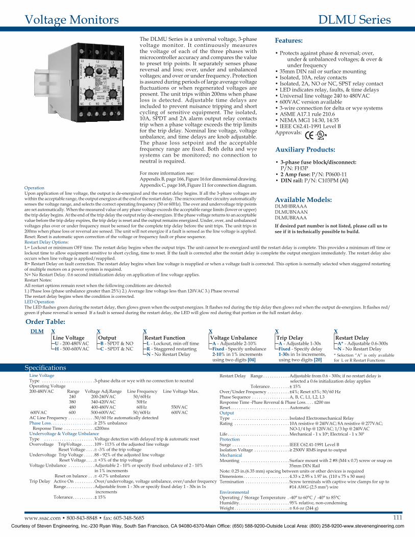
The DLMU Series is a universal voltage, 3-phase voltage monitor. It continuously measures the voltage of each of the three phases with microcontroller accuracy and compares the value to preset trip points. It separately senses phase reversal and loss; over, under and unbalanced voltages; and over or under frequency. Protection is assured during periods of large average voltage fluctuations or when regenerated voltages are present. The unit trips within 200ms when phase loss is detected. Adjustable time delays are included to prevent nuisance tripping and short cycling of sensitive equipment. The isolated, 10A, SPDT and 2A alarm output relay contacts trip when a phase voltage exceeds the trip limits for the trip delay. Nominal line voltage, voltage unbalance, and time delays are knob adjustable. The phase loss setpoint and the acceptable frequency range are fixed. Both delta and wye systems can be monitored; no connection to neutral is required .
For more information see: Appendix B, page 166, Figure 16 for dimensional drawing. Appendix C, page 168, Figure 11 for connection diagram.
If desired part number is not listed, please call us to see if it is technically possible to build .
Courtesy of Steven Engineering, Inc.-230 Ryan Way, South San Francisco, CA 94080-6370-Main Office: (650) 588-9200-Outside Local Area: (800) 258-9200-www.stevenengineering.com
112 www.ssac.com • 800-843-8848 • fax: 605-348-5685
Features:
• Protects against phase loss & reversal; over, under & unbalanced voltages; & over & under frequency
• Encapsulated circuitry • Isolated, 10A, DPDT output contacts• LED indicates relay status, faults, & time
delays• Universal line voltage 200 to 480VAC in
one unit• Compact design• Finger-safe terminal blocks, up to 12 AWG• ASME A17.1 rule 210.6• NEMA MG1 14:30, 14:35• IEEE C62.41-1991 Level BApprovals:
Auxiliary Products:
•3-Phase fuse block/disconnect: P/N: FH3P
•2 Amp fuse: P/N: P0600-11•DIN rail: P/N: C103PM (Al)•DIN rail adaptor: P/N: P1023-20
HLMU SeriesVoltage Monitors
Line VoltageType . . . . . . . . . . . . . . . . . . . . . . . . . . . . . . . 3-phase delta or wye with no connection to neutralOperating Voltage 200 - 480VAC Range Voltage Adj. Range Frequency 240 200-240VAC 50 or 60Hz 380 340-420VAC 50Hz 480 400-480VAC 60HzLine Voltage Max. . . . . . . . . . . . . . . . . . . . 550VACAC Line Frequency . . . . . . . . . . . . . . . . . . 50/60 Hz automatically detectedPhase Loss . . . . . . . . . . . . . . . . . . . . ≥ 25% unbalanceResponse Time . . . . . . . . . . . . . . . . . . . . ≤200msUndervoltage & Voltage UnbalanceType . . . . . . . . . . . . . . . . . . . . . . . . . . . . . . . Voltage detection with delayed trip & automatic resetOvervoltage Trip Voltage . . . . 109 - 113% of the adjusted line voltage Reset Voltage . . . ≅ -3% of the trip voltageUndervoltage Trip Voltage . . . . 88 - 92% of the adjusted line voltage Reset Voltage . . . ≅ +3% of the trip voltageVoltage Unbalance Trip Setpoint . . . . Adjustable 2 - 10% or specify fixed unbalance of 2 - 10% in 1% increments Reset on Balance ≅ -0.7% unbalanceTrip Delay Active On . . . . . . Over/undervoltage, voltage unbalance, over/under frequency Range . . . . . . . . . . Adjustable from 1 - 30s or specify fixed delay 1 - 30s in 1s increments Tolerance . . . . . . . ± 15%Restart Delay Range . . . . . . . . . . Adjustable from 0.6 - 300s; if no restart delay is selected a 0.6s initialization delay applies Tolerance . . . . . . . ± 15%
Over/Under Frequency . . . . . . . . . . . . . . . . . ±4%; Reset ±3%; 50/60 HzPhase Sequence . . . . . . . . . . . . . . . . . . . . . . . A, B, C, L1, L2, L3Response Time-Phase Reversal & Phase Loss. . . . . . ≤200 msReset . . . . . . . . . . . . . . . . . . . . . . . . . . . . . . . . AutomaticOutputType . . . . . . . . . . . . . . . . . . . . . . . . . . . . . . . . . . Isolated Electromechanical RelayForm . . . . . . . . . . . . . . . . . . . . . . . . . . . . . . . . . . DPDTRating . . . . . . . . . . . . . . . . . . . . . . . . . . . . . . . . 10A resistive @ 240VAC; 8A resistive @ 277VAC; NO-1/4 hp @ 120VAC; 1/3 hp @ 240VACLife . . . . . . . . . . . . . . . . . . . . . . . . . . . . . . . . . . . Mechanical - 1 x 10⁶
Electrical (at 10A) - DPDT - 1 x 303
ProtectionSurge . . . . . . . . . . . . . . . . . . . . . . . . . . . . . . . . . IEEE C62.41-1991 Level BIsolation Voltage . . . . . . . . . . . . . . . . . . . . . . . ≥ 2500V RMS input to outputCircuitry . . . . . . . . . . . . . . . . . . . . . . . . . . . . . . EncapsulatedMechanicalMounting . . . . . . . . . . . . . . . . . . . . . . . . . . . . . Surface mount with one #10 (M5 x 0.7) screw Note: 0.25 in.(6.35 mm) spacing between units or other devices is requiredDimensions . . . . . . . . . . . . . . . . . . . . . . . . . . . . 3 x 2 x 1.64 in. (76.7 x 51.3 x 41.7 mm)Termination . . . . . . . . . . . . . . . . . . . . . . . . . . . Screw terminal connection up to 12 AWG (3.3 mm2) wire EnvironmentalOperating / Storage Temperature . . . . . . . . -40° to 60°C / -40° to 85°CHumidity . . . . . . . . . . . . . . . . . . . . . . . . . . . . . . 95% relative, non-condensingWeight . . . . . . . . . . . . . . . . . . . . . . . . . . . . . . . . ≅ 3.9 oz (111 g)
Available Models:
Specifications
Order Table:
HLMUDLAAAHLMUDN0405NHLMUDNAAN
HLMUDRAAAHLMUSR0604A
HLMU X OutputD - DPDTS - SPDT
X Restart FunctionL - Lockout, Min Off TimeR - Staggered RestartingN - No Restart Delay
X Voltage UnbalanceA - Adjustable 2-10%Fixed - Specify Unbalance 2-10% in 1% increments, using two digits [04]
X Trip DelayA - Adjustable 1-30sFixed - Specify delay 1-30s in 1s increments, using two digits [05]
X Restart DelayA* - Adjustable 0.6-300s N - No Restart Delay *Selection “A” is only
available for Restart Functions “L” and “R”
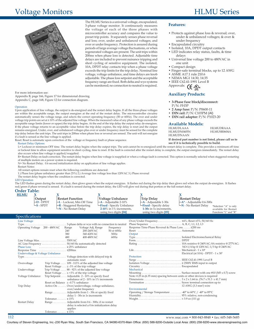
The HLMU Series is a universal voltage, encapsulated, 3-phase voltage monitor. It continuously measures the voltage of each of the three phases with microcontroller accuracy and compares the value to preset trip points. It separately senses phase reversal and loss; over, under and unbalanced voltages; and over or under frequency. Protection is assured during periods of large average voltage fluctuations, or when regenerated voltages are present. The unit trips within 200ms when phase loss is detected. Adjustable time delays are included to prevent nuisance tripping and short cycling of sensitive equipment. The isolated, 10A, DPDT relay contacts trip when a phase voltage exceeds the trip limits for the trip delay. Nominal line voltage, voltage unbalance, and time delays are knob adjustable. The phase loss setpoint and the acceptable frequency range are fixed. Both delta and wye systems can be monitored; no connection to neutral is required .
For more information see:Appendix B, page 166, Figure 17 for dimensional drawing.Appendix C, page 168, Figure 12 for connection diagram.
OperationUpon application of line voltage, the output is de-energized and the restart delay begins. If all the three-phase voltages are within the acceptable range, the output energizes at the end of the restart delay. The microcontroller circuitry automatically senses the voltage range, and selects the correct operating frequency (50 or 60Hz). The over and under voltage trip points are set at ± 10% of the adjusted line voltage. When the measured value of any phase voltage exceeds the acceptable range limits (lower or upper) the trip delay begins. At the end of the trip delay the output relay de-energizes. If the phase voltage returns to an acceptable value before the trip delay expires, the trip delay is reset and the output remains energized. Under, over, and unbalanced voltages plus over or under frequency must be sensed for the complete trip delay before the unit trips. The unit trips in 200ms when phase loss or reversal are sensed. The unit will not energize if a fault is sensed as the line voltage is applied.Reset: Reset is automatic upon correction of the voltage or frequency fault or phase sequence.
Restart Delay Options:L= Lockout or minimum OFF time. The restart delay begins when the output trips. The unit cannot be re-energized until the restart delay is complete. This provides a minimum off time or lockout time to allow equipment sensitive to short cycling, time to reset. If the fault is corrected after the restart delay is complete, the output energizes immediately. The restart delay also occurs when line voltage is applied/reapplied. R= Restart Delay on fault correction. The restart delay begins when line voltage is reapplied or when a voltage fault is corrected. This option is normally selected when staggered restarting of multiple motors on a power system is required.N= No Restart Delay. 0.6 second initialization delay on application of line voltage applies. Restart Notes: All restart options remain reset when the following conditions are detected: 1.) Phase loss (phase unbalance greater than 25%) 2.) Average line voltage less than 120VAC 3.) Phase reversalThe restart delay begins when the condition is corrected.
LED OperationThe LED flashes green during the restart delay, then glows green when the output energizes. It flashes red during the trip delay then glows red when the output de-energizes. It flashes red/green if phase reversal is sensed. If a fault is sensed during the restart delay, the LED will glow red during that portion or the full restart delay.
If desired part number is not listed, please call us to see if it is technically possible to build .
Courtesy of Steven Engineering, Inc.-230 Ryan Way, South San Francisco, CA 94080-6370-Main Office: (650) 588-9200-Outside Local Area: (800) 258-9200-www.stevenengineering.com
113www.ssac.com • 800-843-8848 • fax: 605-348-5685
Features:
• Protects against phase & reversal; & over, under & unbalanced voltages
• Octal plug-in • Isolated, 10A, SPDT output contacts• Operates from 200 to 480VAC• LED indicator glows green when voltages are
acceptable, red for faults• Indicates reverse-phase wiring• Simple 3-wire connection for delta or wye
systems• ASME A17.1 Rule 210.6• NEMA MG1 14:30, 14:35• IEEE C62.41-1991 Level B Approvals:
Auxilary Products:
•Panel mount kit: P/N: BZ1•8-pin octal socket: P/N: OT08PC•3-phase fuse block/disconnect:
P/N: FH3P•2 Amp fuse: P/N: P0600-11•DIN rail: P/N: C103PM (Al)
PLMU SeriesVoltage Monitors
Available Models:
Line VoltageType . . . . . . . . . . . . . . . . . . . . . . . . . . . . . . . . . . . 3-phase delta or wye with no connection to neutralLine Voltage . . . . . . . . . . . . . . . . . . . . . . . . . . . . 200 to 480VAC ±15%, 50/60 Hz ±2 HzAdjustable Voltage Ranges (Automatic Range Selection) . . . . . . . . . . . . 200 to 240VAC, 50/60 Hz 340 to 420VAC, 50 Hz 400 to 480VAC, 60 HzMaximum Voltage . . . . . . . . . . . . . . . . . . . . . . 552VACPhase Sequence . . . . . . . . . . . . . . . . . . . . . . . . . ABCOvervoltage, Undervoltage, & Voltage UnbalanceType . . . . . . . . . . . . . . . . . . . . . . . . . . . . . . . . . . . Voltage detection with delayed trip & automatic resetOvervoltage & Undervoltage Undervoltage Trip Point . . . . . . . . . . . . . . . 88 - 92% of adjusted line voltage Reset Voltage . . . . . . . . . . . . . . . . . . . . . . . . . +2% of trip voltage Overvoltage Trip Point . . . . . . . . . . . . . . . . 109 - 113% of adjusted line voltage Reset Voltage . . . . . . . . . . . . . . . . . . . . . . . . . -2% of trip voltageVoltage Unbalance Trip Point . . . . . . . . . . . . . Adjustable from 2 - 10% Factory fixed from 4 - 10% (a minimum order quantity applies)Reset on Balance (%): Selected Unbalance 2 3 4 5 6 7 8 9 10 Reset 1.5 2.5 3.5 4.5 5.4 6.3 7.2 8.1 9
Trip Delay Range . . . . . . . . . . . . . . . . . . . . . . . . Adjustable from 0.25 - 30s Factory fixed from 2 - 30s ±15% (a minimum order quantity applies)Severe Unbalance - 2X Selected Unbalance . 0.25 - 2s; disabled when the trip delay is less than 2sRandom Start Delay . . . . . . . . . . . . . . . . . . . . . ≅ 0.6sPhase Reversal & Phase Loss Trip Time . . . . ≤ 150msPhase Loss Setpoint . . . . . . . . . . . . . . . . . . . . . . ≥ 15% unbalanceReset Type . . . . . . . . . . . . . . . . . . . . . . . . . . . . . AutomaticOutput Type . . . . . . . . . . . . . . . . . . . . . . . . . . . . Energized when voltages are acceptableRating . . . . . . . . . . . . . . . . . . . . . . . . . . . . . . . . . 10A resistive @ 240VAC; 1/4 hp @ 125VAC; 1/3 hp @ 250VAC; max. 277VACLife . . . . . . . . . . . . . . . . . . . . . . . . . . . . . . . . . . . . Mechanical - 1 x 10⁶ ; Electrical - 1 x 10⁵
ProtectionSurge . . . . . . . . . . . . . . . . . . . . . . . . . . . . . . . . . . IEEE C62.41-1991 Level BIsolation Voltage . . . . . . . . . . . . . . . . . . . . . . . . ≥ 2500V RMS input to outputMechanicalMounting* . . . . . . . . . . . . . . . . . . . . . . . . . . . . . . Plug-in socket rated 600VACTermination . . . . . . . . . . . . . . . . . . . . . . . . . . . . Octal 8-pin plug-in Dimensions . . . . . . . . . . . . . . . . . . . . . . . . . . . . . 3.03 x 2.39 x 1.78 in. (77.0 x 60.7 x 45.2 mm)EnvironmentalOperating / Storage Temperature . . . . . . . . . -40° to 60°C / -40° to 85°CWeight . . . . . . . . . . . . . . . . . . . . . . . . . . . . . . . . . ≅ 8.6 oz (244 g)
*CAUTION: Select an octal socket rated for 600VAC operation.
Specifications
Order Table: Voltage Unbalance
Adjustable 2-10% Trip Delay
Adjustable 0.25-30sPart Number
PLMU11
PLMU11
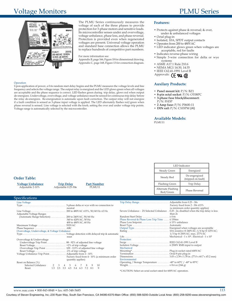
The PLMU Series continuously measures the voltage of each of the three phases to provide protection for 3-phase motors and sensitive loads. Its microcontroller senses under and overvoltage, voltage unbalance, phase loss, and phase reversal. Protection is provided even when regenerated voltages are present. Universal voltage operation and standard base connection allows the PLMU to replace hundreds of competitive part numbers.
For more information see:Appendix B, page 166, Figure 18 for dimensional drawing.Appendix C, page 168, Figure 13 for connection diagram.
OperationUpon application of power, a 0.6s random start delay begins and the PLMU measures the voltage levels and line frequency and selects the voltage range. The output relay is energized and the LED glows green when all voltages are acceptable and the phase sequence is correct. LED flashes green during trip delay, glows red when output de-energizes. Undervoltage, overvoltage, and voltage unbalance must be sensed for continuous trip delay before the relay de-energizes. Re-energization is automatic upon fault correction. The output relay will not energize if a fault condition is sensed as 3-phase input voltage is applied. The LED alternately flashes red/green when phase reversal is sensed. Line voltage is selected with the knob, setting the over and under voltage trip points. Voltage range is automatically selected by the microcontroller.
LED Indicator
Steady Green Energized
Steady Red De-engergized (tripped on fault)
Flashing Green Trip Delay
Alternate Flashing Red/Green Phase Reversal
Courtesy of Steven Engineering, Inc.-230 Ryan Way, South San Francisco, CA 94080-6370-Main Office: (650) 588-9200-Outside Local Area: (800) 258-9200-www.stevenengineering.com
114 www.ssac.com • 800-843-8848 • fax: 605-348-5685
Features:
• Protects against phase loss & reversal; & under & unbalanced voltages
• 8-pin plug-in base• Adjustable low voltage trip point• Factory fixed unbalance & trip delay• Line voltages 200 to 480VAC in 3 ranges• Isolated, 10A, SPDT output contacts• ASME A17.1 rule 210.6• NEMA MG1 14:30, 14:35• IEEE C62.41-1991 Level BApprovals:
Auxiliary Products:
•Panel mount kit: P/N: BZ1•Octal 8-pin socket: P/N: OT08PC•3-phase fuse block/disconnect:
P/N: FH3P•2 Amp fuse: P/N: P0600-11•DIN rail: P/N: C103PM (Al)
PLM SeriesVoltage Monitors
Line VoltageType . . . . . . . . . . . . . . . . . . . . . . . . . . . . . . . . . . . . . . . 3-phase delta or wye with no connection to neutralOperating Voltage: Model Adj. Line Voltage Range Line Voltage Max. 240 200-240VAC 270VAC 380 360-430VAC 480VAC 480 400-480VAC 530VACAC Line Frequency . . . . . . . . . . . . . . . . . . . . . . . . . . 50/100 HzPhase Sequence . . . . . . . . . . . . . . . . . . . . . . . . . . . . . ABCPower Consumption . . . . . . . . . . . . . . . . . . . . . . . . . ≅ 2W for 240V units ≅ 3W for 380 - 480V unitsLow Voltage & Voltage UnbalanceType . . . . . . . . . . . . . . . . . . . . . . . . . . . . . . . . . . . . . . . Voltage detection with delayed trip & automatic resetLow Voltage Trip Voltage . . . . . . 88 - 92% of adjusted line voltage Reset Voltage . . . . . Plus 3% of trip voltageVoltage Unbalance Trip Unbalance . . . Factory fixed from 4 - 8% Reset on Balance . . -0.7% unbalance typicalTrip Delay Range . . . . . . . . . . . Factory fixed from 2 - 20s Tolerance . . . . . . . . ±15% Phase Reversal & Phase LossResponse Time: Phase Reversal . . . . . . ≤ 200ms Phase Loss . . . . . . . . . . ≤ 200ms
Phase Loss . . . . . . . . . . . . . . . . . . . . . . . . . . . . . > 35% unbalanceReset . . . . . . . . . . . . . . . . . . . . . . . . . . . . . . . . . . AutomaticOutputType . . . . . . . . . . . . . . . . . . . . . . . . . . . . . . . . . . Electromechanical relayForm . . . . . . . . . . . . . . . . . . . . . . . . . . . . . . . . . . Isolated, SPDTRating . . . . . . . . . . . . . . . . . . . . . . . . . . . . . . . . 10A resistive @ 240VAC, 277VAC max; 1/2 Hp @ 240VAC; 1/4 Hp @ 120VACLife . . . . . . . . . . . . . . . . . . . . . . . . . . . . . . . . . . . Mechanical - 1 x 10⁷; Electrical - 1 x 10
5
ProtectionSurge . . . . . . . . . . . . . . . . . . . . . . . . . . . . . . . . . IEEE C62.41-1991 Level BIsolation Voltage . . . . . . . . . . . . . . . . . . . . . . . ≥ 2500V RMS input to outputMechanicalMounting* . . . . . . . . . . . . . . . . . . . . . . . . . . . . . 8-pin plug-in socket rated 600VACDimensions . . . . . . . . . . . . . . . . . . . . . . . . . . . . 3.2 x 2.39 x 1.78 in. (81.3 x 60.7 x 45.2 mm)EnvironmentalOperating / Storage Temperature . . . . . . . . -40° to 60°C / -40° to 85°CWeight . . . . . . . . . . . . . . . . . . . . . . . . . . . . . . . . ≅ 4.4 oz (125 g)
*CAUTION: Select an octal socket rated for 600VAC operation.
Available Models:
Specifications
Order Table: PLM X
Line Voltage6 - 240VAC8 - 380VAC9 - 480VAC
X Voltage UnbalancedFixed - Specify - 4-8% in 1% increments
X Trip DelayFixed - Specify from 2-20s in 1s increments using two digits
PLM6405PLM6502PLM6805PLM8405PLM8805
PLM9405PLM9502PLM9805PLM9820
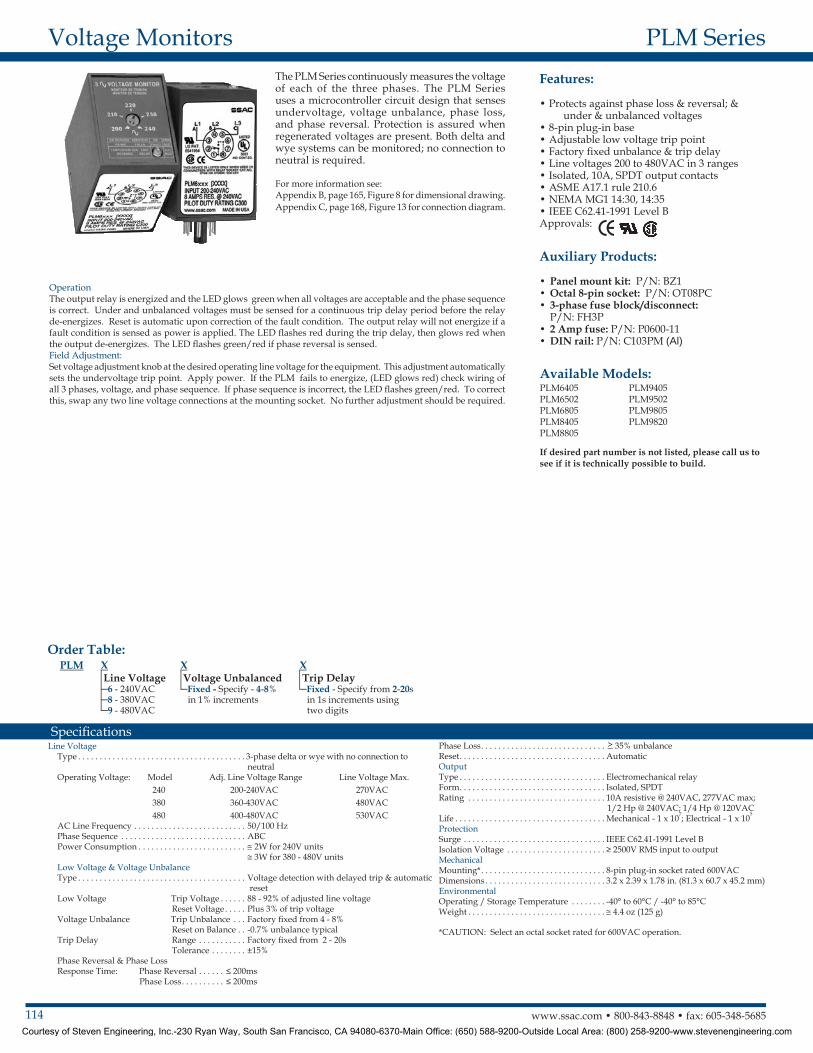
The PLM Series continuously measures the voltage of each of the three phases. The PLM Series uses a microcontroller circuit design that senses undervoltage, voltage unbalance, phase loss, and phase reversal. Protection is assured when regenerated voltages are present. Both delta and wye systems can be monitored; no connection to neutral is required .
For more information see:Appendix B, page 165, Figure 8 for dimensional drawing.Appendix C, page 168, Figure 13 for connection diagram.
OperationThe output relay is energized and the LED glows green when all voltages are acceptable and the phase sequence is correct. Under and unbalanced voltages must be sensed for a continuous trip delay period before the relay de-energizes. Reset is automatic upon correction of the fault condition. The output relay will not energize if a fault condition is sensed as power is applied. The LED flashes red during the trip delay, then glows red when the output de-energizes. The LED flashes green/red if phase reversal is sensed.Field Adjustment: Set voltage adjustment knob at the desired operating line voltage for the equipment. This adjustment automatically sets the undervoltage trip point. Apply power. If the PLM fails to energize, (LED glows red) check wiring of all 3 phases, voltage, and phase sequence. If phase sequence is incorrect, the LED flashes green/red. To correct this, swap any two line voltage connections at the mounting socket. No further adjustment should be required.
If desired part number is not listed, please call us to see if it is technically possible to build .
Courtesy of Steven Engineering, Inc.-230 Ryan Way, South San Francisco, CA 94080-6370-Main Office: (650) 588-9200-Outside Local Area: (800) 258-9200-www.stevenengineering.com
115www.ssac.com • 800-843-8848 • fax: 605-348-5685
Features:
• Protects against phase loss & reversal; over, under & unbalanced voltages; short cycling
• Fixed trip points & delays• Adjustable voltages from 208 to 480VAC
in 4 ranges• Monitor 600VAC lines by connecting VRM
accessory• Isolated, 10A, SPDT output contacts• Bi-color LED indicates: output status, faults,
time delays, phase reversal & setpoint• ASME A17.1 rule 210.6• NEMA MG1 14:30, 14:35• IEEE C62.41-1991 Level B Approvals:
Auxilary Products:
•3-phase fuse block/disconnect: P/N: FH3P
•2 Amp fuse: P/N: P0600-11•DIN rail: P/N: C103PM (Al)•Female quick connect:
P/N: P1015-13 (AWG 10/12) P/N: P1015-64 (AWG 14/16) P/N: P1015-14 (AWG 18/22)
•Voltage reduction module: P/N: VRM6048
TVW SeriesVoltage Monitors
Available Models:
Line VoltageType . . . . . . . . . . . . . . . . . . . . . . . . . . . . . . . . . . . . . 3-phase delta or wye with no connection to neutralInput Voltage/Tolerance . . . . . . . . . . . . . . . . . . . 208 to 480VAC in 4 ranges/-30% - 20%AC Line Frequency . . . . . . . . . . . . . . . . . . . . . . . . 50 - 100 HzPhase Sequence . . . . . . . . . . . . . . . . . . . . . . . . . . . ABCPower Consumption . . . . . . . . . . . . . . . . . . . . . . . Approx. 2W for 240V units Approx. 3W for 480V unitsOvervoltage, Undervoltage, & Voltage Unbalance Overvoltage & Undervoltage . . . . . . . . . . . . . . . . Voltage detection with delay trip & automatic reset Undervoltage Trip Point . . . . . . . . . . . . . . . . . . . . 88 - 92% of the selected line voltageReset Voltage . . . . . . . . . . . . . . . . . . . . . . . . . . . . . ≅ +3% of trip voltageOvervoltage Trip Point . . . . . . . . . . . . . . . . . . . . . 109 - 113% of the selected line voltageReset Voltage . . . . . . . . . . . . . . . . . . . . . . . . . . . . . ≅ -3% of trip voltageTrip Variation vs Temperature . . . . . . . . . . . . . . ≤ ±2%Voltage Unbalance . . . . . . . . . . . . . . . . . . . . . . . Factory fixed, from 4 - 10%Reset On Balance . . . . . . . . . . . . . . . . . . . . . . . . . . ≅ -0.7% unbalanceTrip Delay Range . . . . . . . . . . . . . . . . . . . . . . . . . . Fixed from 0.2 - 100s ±15% or ±0.1s, whichever is greaterRestart Delay Range . . . . . . . . . . . . . . . . . . . . . . . Fixed from 0.4s - 999m ±15% or ±0.2s, whichever is greater
Phase Reversal & Phase Loss Response . . . . . . . ≤ 200ms; automatic resetPhase Loss . . . . . . . . . . . . . . . . . . . . . . . . . . . . . . . . ≥ 25% unbalanceOutputType . . . . . . . . . . . . . . . . . . . . . . . . . . . . . . . . . . . . . Isolated, SPDTRating 208 to 240VAC (55°C) . . . . . . 10A resistive @ 125VAC, 5A @ 250VAC, 1/4 hp @ 125VAC 380 to 480VAC . . . . . . . . . . . . 10A resistive @ 240VAC, 1/4 hp @ 125VAC, 1/3 hp @ 250VAC, max. voltage 277VACLife . . . . . . . . . . . . . . . . . . . . . . . . . . . . . . . . . . . . . . Mechanical - 1 x 10⁶; Electrical - 1 x 10⁵
ProtectionSurge . . . . . . . . . . . . . . . . . . . . . . . . . . . . . . . . . . . . IEEE C62.41-1991 Level BDielectric Breakdown 208 to 240VAC . . . . . . . ≥ 1500V RMS input to output terminals 380 to 480VAC . . . . . . ≥ 2500V RMS input to output terminalsMechanical Mounting . . . . . . . . . . . . . . . . . . . . . . . . . . . . . . . . Surface mount with one #8 (M5 x 0.8) screwDimensions . . . . . . . . . . . . . . . . . . . . . . . . . . . . . . .2 x 2 x 1.25 in. (50.8 x 50.8 x 31.8 mm)Termination . . . . . . . . . . . . . . . . . . . . . . . . . . . . . . 0.25 in. (6.35 mm) male quick connect terminalsEnvironmentalOperating / Storage Temperature . . . . . . . . . . . -40° to 55°C / -40° to 85°CHumidity . . . . . . . . . . . . . . . . . . . . . . . . . . . . . . . . . 95% relative, non-condensingWeight . . . . . . . . . . . . . . . . . . . . . . . . . . . . . . . . . . . ≅ 2.8 oz (79 g)
Specifications
TVW575S1MTVW6510S0.4STVW9510S0.4S
Order Table: TVW X
Line Voltage Wide Range5 - 208-240VAC
Selectable6 - 208, 220, 230 & 240VAC8 - 380, 400 & 415VAC9 - 430, 440, 460 & 480VAC
X Voltage UnbalanceFixed - Specify 4-10% in 1% increments
X Trip Delay*Fixed - Specify from 0 .2-1s in 0.1s incrementsFixed - Specify from 1-100s in 1s increments
*Must indicate (S) for secs. or (M) for mins.
X Restart Delay*Fixed - Specify from 0 .4-1s in 0.1s incrementsFixed - Specify from 1-100s in 1s incrementsFixed - Specify from 1-999min in 1min increments
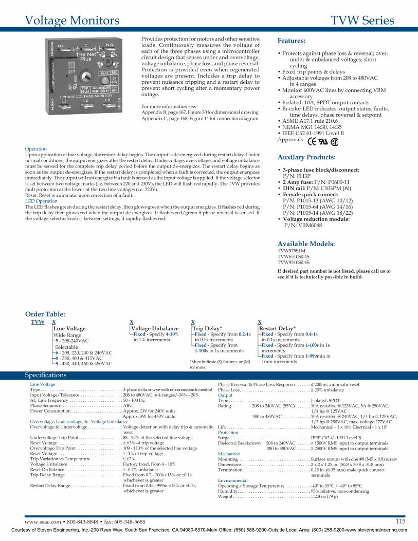
Provides protection for motors and other sensitive loads. Continuously measures the voltage of each of the three phases using a microcontroller circuit design that senses under and overvoltage, voltage unbalance, phase loss, and phase reversal. Protection is provided even when regenerated voltages are present. Includes a trip delay to prevent nuisance tripping and a restart delay to prevent short cycling after a momentary power outage .
For more information see:Appendix B, page 167, Figure 30 for dimensional drawing.Appendix C, page 168, Figure 14 for connection diagram.
OperationUpon application of line voltage, the restart delay begins. The output is de-energized during restart delay. Under normal conditions, the output energizes after the restart delay. Undervoltage, overvoltage, and voltage unbalance must be sensed for the complete trip delay period before the output de-energizes. The restart delay begins as soon as the output de-energizes. If the restart delay is completed when a fault is corrected, the output energizes immediately. The output will not energize if a fault is sensed as the input voltage is applied. If the voltage selector is set between two voltage marks (i.e. between 220 and 230V), the LED will flash red rapidly. The TVW provides fault protection at the lower of the two line voltages (i.e. 220V).Reset: Reset is automatic upon correction of a fault. LED OperationThe LED flashes green during the restart delay, then glows green when the output energizes. It flashes red during the trip delay then glows red when the output de-energizes. It flashes red/green if phase reversal is sensed. If the voltage selector knob is between settings, it rapidly flashes red.
If desired part number is not listed, please call us to see if it is technically possible to build .
Courtesy of Steven Engineering, Inc.-230 Ryan Way, South San Francisco, CA 94080-6370-Main Office: (650) 588-9200-Outside Local Area: (800) 258-9200-www.stevenengineering.com
116 www.ssac.com • 800-843-8848 • fax: 605-348-5685
TVM SeriesVoltage Monitors
Line VoltageType . . . . . . . . . . . . . . . . . . . . . . . . . . . . . . . . . . . 3-phase delta or wye with no connection to neutralInput Voltage . . . . . . . . . . . . . . . . . . . . . . . . . . . . 208 to 480VAC AC Line Frequency . . . . . . . . . . . . . . . . . . . . . . . 50 - 100 HzPhase Sequence . . . . . . . . . . . . . . . . . . . . . . . . . . ABCPower Consumption . . . . . . . . . . . . . . . . . . . . . Approx. 2W for 240V units Approx. 3W for 480V unitsOvervoltage, Undervoltage, & Voltage Unbalance Overvoltage & Undervoltage . . . . . . . . . . . . . . Voltage detection with delay trip & automatic reset Undervoltage Trip Point . . . . . . . . . . . . . . . . . 88 - 92% of the selected line voltage Reset Voltage . . . . . . . . . . . . . . . . . . . . . . . . . . ≅ +3% of trip voltage Overvoltage Trip Point . . . . . . . . . . . . . . . . . . 109 - 113% of the selected line voltage Reset Voltage . . . . . . . . . . . . . . . . . . . . . . . . . . ≅ -3% of trip voltage Trip Variation vs Temperature . . . . . . . . . . . ≤ ±2%Voltage Unbalance . . . . . . . . . . . . . . . . . . . . . . Factory fixed from 4 - 10%Reset On Balance . . . . . . . . . . . . . . . . . . . . . . . . . ≅ -0.7% unbalanceTrip Delay Range . . . . . . . . . . . . . . . . . . . . . . . . Fixed from 0.2 - 100s ±15% or ±0.1s, whichever is greaterRestart Delay Range . . . . . . . . . . . . . . . . . . . . . . Fixed from 0.5s - 999m ±15% or ±0.2s, whichever is greaterPhase Reversal & Phase Loss Response . . . . . ≤ 200ms; automatic resetPhase Loss . . . . . . . . . . . . . . . . . . . . . . . . . . . . . . ≥ 25% unbalance
OutputType . . . . . . . . . . . . . . . . . . . . . . . . . . . . . . . . . . . Isolated SPDT relay contactsRating 208 to 240VAC (55°C) . . . . . 10A resistive @ 125VAC, 5A @ 250VAC, 1/4 hp @ 125VAC 380 to 480VAC . . . . . . . . . . . 10A resistive @ 240VAC, 1/4 hp @ 125VAC, 1/3 hp @ 250VAC, max. voltage 277VACLife . . . . . . . . . . . . . . . . . . . . . . . . . . . . . . . . . . . . Mechanical - 1 x 10⁶; Electrical - 1 x 10⁵
ProtectionSurge . . . . . . . . . . . . . . . . . . . . . . . . . . . . . . . . . . . IEEE C62.41-1991 Level BDielectric Breakdown 208 to 240VAC . . . . . ≥ 1500V RMS input to output terminals 380 to 480VAC . . . . . ≥ 2500V RMS input to output terminalsMechanical Mounting . . . . . . . . . . . . . . . . . . . . . . . . . . . . . . . Surface mount with one #8 (M5 x 0.8) screwDimensions . . . . . . . . . . . . . . . . . . . . . . . . . . . . . 2 x 2 x 1.25 in. (50.8 x 50.8 x 31.8 mm)Termination . . . . . . . . . . . . . . . . . . . . . . . . . . . . . 0.25 in. (6.35 mm) male quick connect terminalsEnvironmentalOperating / Storage Temperature . . . . . . . . . -40° to 55°C / -40° to 85°CHumidity . . . . . . . . . . . . . . . . . . . . . . . . . . . . . . . 95% relative, non-condensingWeight . . . . . . . . . . . . . . . . . . . . . . . . . . . . . . . . . ≅ 2.8 oz (79 g)
Available Models:
Features:
• Protects against phase loss & reversal; over, under & unbalanced voltages; short cycling
• Fixed trip points & delays• Fixed voltages from 208 to 480VAC• Isolated, 10A, SPDT ouput contacts• Bi-color LED indicator shows: output status,
faults, time delays & phase reversal• ASME A17.1 rule 210.6• NEMA MG1 14:30, 14:35• IEEE C62.41-1991 Level BApprovals:
Auxiliary Products:
•Female quick connect: P/N: P1015-13 (AWG 10/12) P/N: P1015-64 (AWG 14/16) P/N: P1015-14 (AWG 18/22)
•3-phase fuse block/disconnect: P/N: FH3P
•2 Amp fuse: P/N: P0600-11•Voltage reduction module: P/N: VRM6048
Specifications
Order Table: TVM X
Line Voltage208A - 208VAC220A - 220VAC230A - 230VAC240A - 240VAC380A - 380VAC400A - 400VAC415A - 415VAC440A - 440VAC460A - 460VAC480A - 480VAC
X Voltage UnbalanceFixed - Specify 4-10% in 1% increments
X Trip Delay*Fixed - Specify from 0 .2-1s in 0.1s incrementsFixed - Specify from 1-100s in 1s increments
*Must indicate (S) for secs. or (M) for mins.
X Restart Delay*Fixed - Specify from 0 .5-1s in 0.1s incrementsFixed - Specify from 1-100s in 1s incrementsFixed - Specify from 1-999min in 1min increments
TVM208A100.5S3STVM230A101S1STVM400A101S1STVM460A101S1STVM460A41S5M
TVM460A510S5STVM460A75S2MTVM480A100.5S3STVM480A50.5S2S
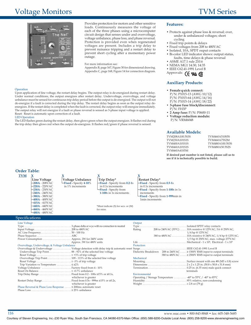
Provides protection for motors and other sensitive loads. Continuously measures the voltage of each of the three phases using a microcomputer circuit design that senses under and overvoltage, voltage unbalance, phase loss, and phase reversal. Protection is provided even when regenerated voltages are present. Includes a trip delay to prevent nuisance tripping and a restart delay to prevent short cycling after a momentary power outage .
For more information see:Appendix B, page 167, Figure 30 for dimensional drawing.Appendix C, page 168, Figure 14 for connection diagram.
OperationUpon application of line voltage, the restart delay begins. The output relay is de-energized during restart delay. Under normal conditions, the output energizes after restart delay. Undervoltage, overvoltage, and voltage unbalance must be sensed for continuous trip delay period before the output is de-energized. The output will not de-energize if a fault is corrected during the trip delay. The restart delay begins as soon as the output relay de-energizes. If the restart delay is completed when the fault is corrected, the output relay will energize immediately.The output relay will not energize if a fault or phase reversal is sensed as 3-phase input voltage is applied.Reset: Reset is automatic upon correction of a fault. LED OperationThe LED flashes green during the restart delay, then glows green when the output energizes. It flashes red during the trip delay then glows red when the output de-energizes. It flashes red/green if phase reversal is sensed.
If desired part number is not listed, please call us to see if it is technically possible to build .
Courtesy of Steven Engineering, Inc.-230 Ryan Way, South San Francisco, CA 94080-6370-Main Office: (650) 588-9200-Outside Local Area: (800) 258-9200-www.stevenengineering.com
117www.ssac.com • 800-843-8848 • fax: 605-348-5685
Features:
• Protects against phase loss (on startup), phase reversal & undervoltage
• Used where moderate voltage unbalance protection is not required
• Direct replacement for most popular 3-phase monitors
• 8-pin octal base connection• Isolated, 5A, SPDT output contacts• AMSE A17.1 rule 210.6• NEMA MG1 14:30, 14:35 • IEEE C62.41-1991 Level B Approvals:
Auxilary Products:
•Panel mount kit: P/N: BZ1•Octal 8-pin socket: P/N: OT08PC•3-phase fuse block/disconnect:
P/N: FH3P•2 Amp fuse: P/N: P0600-11•DIN rail: P/N: C103PM (Al)
PLR SeriesVoltage Monitors
Line VoltageType . . . . . . . . . . . . . . . . . . . . . . . . . . . . . 3-phase delta or wye with no connection to neutralNominal Voltage Undervoltage Dropout Adj Range Line Voltage Max. 120VAC 85 to 130VAC 143VAC 240VAC 170 to 240VAC 270VAC 380VAC 310 to 410VAC 480VAC 480VAC 350 to 480VAC 530VACAC Line Frequency . . . . . . . . . . . . . . . . 50/60HzPhase Sequence . . . . . . . . . . . . . . . . . . . ABCResponse TimesPull-in . . . . . . . . . . . . . . . . . . . . . . . . . . . ≤ 400msDrop-out . . . . . . . . . . . . . . . . . . . . . . . . . ≤ 100msHysterisis Pull-in/Drop-out . . . . ≅ 2%OutputType . . . . . . . . . . . . . . . . . . . . . . . . . . . . . Electromechanical relay, energized when all voltages are acceptableForm . . . . . . . . . . . . . . . . . . . . . . . . . . . . . SPDTRating . . . . . . . . . . . . . . . . . . . . . . . . . . . 5A resistive @ 240VAC, 1/4 Hp @ 120VACMaximum Voltage . . . . . . . . . . . . . . . . . 250VAC
Protection Surge . . . . . . . . . . . . . . . . . . . . . . . . . . . . IEEE C62.41-1991 Level BIsolation Voltage 120 & 240VAC . . . . . . . . . . . . .≥ 1500V RMS input to output 380 & 480VAC . . . . . . . . . . . . .≥ 2500V RMS input to outputMechanicalDimensions . . . . . . . . . . . . . . . . . . . . . . . 3.2 x 2.39 x 1.78 in. (81.3 x 60.7 x 45.2 mm)Mounting* . . . . . . . . . . . . . . . . . . . . . . . . Plug-in socketTermination . . . . . . . . . . . . . . . . . . . . . . Octal 8-pin, plug-inEnvironmentalOperating/ Storage Temperature . . . . 0° to 55°C / -40° to 85°CWeight . . . . . . . . . . . . . . . . . . . . . . . . . . . ≅ 6 oz (170 g)
*CAUTION: Select an octal socket rated for 600VAC operation.
Specifications
Available Models:
Order Table:
PLR120APLR240APLR380APLR480A
Voltage95-140VAC190-270VAC340-450VAC380-500VAC
Part NumberPLR120APLR240APLR380APLR480A
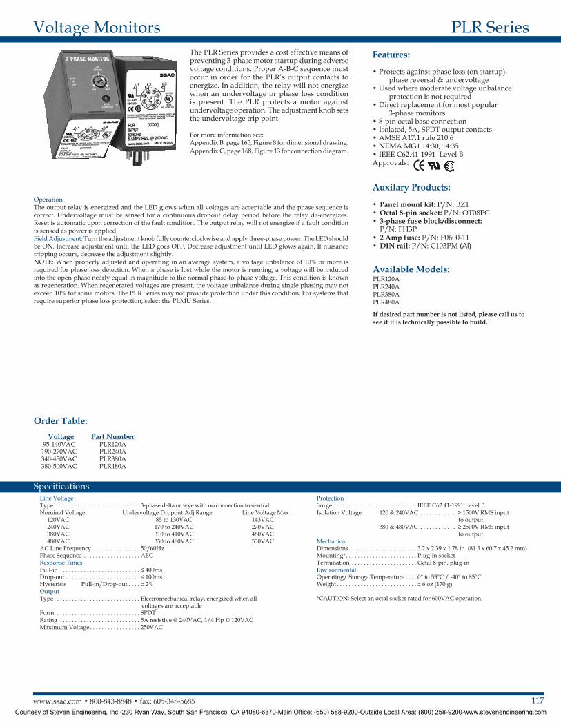
The PLR Series provides a cost effective means of preventing 3-phase motor startup during adverse voltage conditions. Proper A-B-C sequence must occur in order for the PLR’s output contacts to energize. In addition, the relay will not energize when an undervoltage or phase loss condition is present. The PLR protects a motor against undervoltage operation. The adjustment knob sets the undervoltage trip point.
For more information see:Appendix B, page 165, Figure 8 for dimensional drawing.Appendix C, page 168, Figure 13 for connection diagram.
OperationThe output relay is energized and the LED glows when all voltages are acceptable and the phase sequence is correct. Undervoltage must be sensed for a continuous dropout delay period before the relay de-energizes. Reset is automatic upon correction of the fault condition. The output relay will not energize if a fault condition is sensed as power is applied . Field Adjustment: Turn the adjustment knob fully counterclockwise and apply three-phase power. The LED should be ON. Increase adjustment until the LED goes OFF. Decrease adjustment until LED glows again. If nuisance tripping occurs, decrease the adjustment slightly.NOTE: When properly adjusted and operating in an average system, a voltage unbalance of 10% or more is required for phase loss detection. When a phase is lost while the motor is running, a voltage will be induced into the open phase nearly equal in magnitude to the normal phase-to-phase voltage. This condition is known as regeneration. When regenerated voltages are present, the voltage unbalance during single phasing may not exceed 10% for some motors. The PLR Series may not provide protection under this condition. For systems that require superior phase loss protection, select the PLMU Series.
If desired part number is not listed, please call us to see if it is technically possible to build .
Courtesy of Steven Engineering, Inc.-230 Ryan Way, South San Francisco, CA 94080-6370-Main Office: (650) 588-9200-Outside Local Area: (800) 258-9200-www.stevenengineering.com
118 www.ssac.com • 800-843-8848 • fax: 605-348-5685
PLS SeriesVoltage Monitors
Line VoltageType . . . . . . . . . . . . . . . . . . . . . . . . . . . . . . . . . . . 3-phase delta or wye with no connection to neutral Nominal Voltage Minimum Voltage Maximum Voltage 120VAC 95VAC 135VAC 208/240VAC 175VAC 255VAC 380/415VAC 310VAC 430VAC 440/480VAC 380VAC 500VACAC Line Frequency . . . . . . . . . . . . . . . . . . . . . . 50/60 HzPhase Sequence . . . . . . . . . . . . . . . . . . . . . . . . . ABC Response TimesPull-in . . . . . . . . . . . . . . . . . . . . . . . . . . . . . . . . . ≤ 300ms Drop-out . . . . . . . . . . . . . . . . . . . . . . . . . . . . . . . ≤ 50msOutputType . . . . . . . . . . . . . . . . . . . . . . . . . . . . . . . . . . . Electromechanical relay, energized when the phase sequence is correctForm . . . . . . . . . . . . . . . . . . . . . . . . . . . . . . . . . . . Isolated SPDTRating 120 & 240VAC . . . . . . 10A resistive @ 240VAC 380 & 480VAC . . . . . 8A resistive @ 240VAC
Maximum Voltage . . . . . . . . . . . . . . . . . . . . . . . 250VACProtectionIsolation Voltage 120 & 240VAC . . . ≥ 1500V RMS input to output 380 & 480VAC . . . ≥ 2500V RMS input to outputMechanicalMounting* . . . . . . . . . . . . . . . . . . . . . . . . . . . . . . Plug-in socketDimensions . . . . . . . . . . . . . . . . . . . . . . . . . . . . . 3.2 x 2.39 x 1.78 in. (81.3 x 60.7 x 45.2 mm)Termination . . . . . . . . . . . . . . . . . . . . . . . . . . . . Octal 8-pin plug-inEnvironmentalOperating / Storage Temperature . . . . . . . . . -40°to 55°C / -40° to 85°CWeight . . . . . . . . . . . . . . . . . . . . . . . . . . . . . . . . . ≅ 6 oz (170 g)
*CAUTION: Select an octal socket rated for 600VAC operation.
Available Models:
Specifications
Order Table:
PLS120APLS240APLS480A
Auxilary Products:
•Panel mount kit: P/N: BZ1•Octal 8-pin socket: P/N: OT08PC•3-phase fuse block/disconnect:
P/N: FH3P•2 Amp fuse: P/N: P0600-11•Din rail: P/N: C103PM (Al)
Voltage120VAC
208/240VAC380/415VAC440/480VAC
Part NumberPLS120APLS240APLS380APLS480A
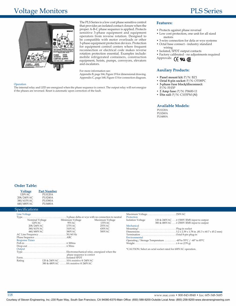
The PLS Series is a low cost phase sensitive control that provides an isolated contact closure when the proper A-B-C phase sequence is applied. Protects sensitive 3-phase equipment and equipment operators from reverse rotation. Designed to be compatible with motor overloads or other 3-phase equipment protection devices. Protection for equipment control centers where frequent reconnection or electrical code makes reverse rotation protection essential. Examples include: mobile refrigerated containers, construction equipment, hoists, pumps, conveyors, elevators and escalators .
For more information see:Appendix B, page 166, Figure 19 for dimensional drawing.Appendix C, page 168, Figure 13 for connection diagram.
OperationThe internal relay and LED are energized when the phase sequence is correct. The output relay will not energize if the phases are reversed. Reset is automatic upon correction of the fault.
Features:
• Protects against phase reversal• Low cost protection, one unit for all sized
motors• 3-wire connection for dela or wye systems• Octal base connect - industry standard
wiring• Isolated, SPDT output contacts• Factory calibrated - no adjustments requiredApprovals:
Courtesy of Steven Engineering, Inc.-230 Ryan Way, South San Francisco, CA 94080-6370-Main Office: (650) 588-9200-Outside Local Area: (800) 258-9200-www.stevenengineering.com
119www.ssac.com • 800-843-8848 • fax: 605-348-5685
Features:
• Protects against undervoltage in single-phase systems
• 30A, SPDT, NO output contacts• 100 to 240VAC input voltage• 70 to 220VAC adjustable undervoltage trip
point in 2 ranges• Restart delays from 3 - 300s• Trip delay 1 - 20s fixed• Isolated or non-isolated relay contactsApprovals:
Auxiliary Products:
•Quick connect to screw adaptor: P/N: P1015-18
•Female quick connect: P/N: P1015-13 (AWG 10/12) P/N: P1015-64 (AWG 14/16)
•Mounting bracket: P/N: P1023-6•DIN rail: P/N: C103PM (Al)•DIN rail adaptor: P/N: P1023-20
HLV SeriesVoltage Monitors
InputMin & Max RMS Voltage . . . . . . . . . . . . . . . .70 to 264VACAC Line Frequency . . . . . . . . . . . . . . . . . . . . .50/60 HzPower Consumption . . . . . . . . . . . . . . . . . . . .AC ≤ 4VAUndervoltage SensingType . . . . . . . . . . . . . . . . . . . . . . . . . . . . . . . . . .Peak voltage sensingRanges (4) . . . . . . . . . . . . . .70 to 120VAC (6) . . . . . . . . . . . . . .170 to 220VAC Pull-In Voltage . . . . . . . . . . . . . . . . . . . . . . . . .105% or trip point voltageTrip Point Accuracy . . . . . . . . . . . . . . . . . . . . .± 3% of trip pointTime DelayRestart Delays . . . . . . . . . . . . . . . . . . . . . . . . . .3 - 300s adjustable Trip Delay . . . . . . . . . . . . . . . . . . . . . . . . . . . . .1 - 20s fixed in 1s increments Repeat Accuracy . . . . . . . . . . . . . . . . . . . . . . .±0.5% or 20ms, whichever is greaterTolerance (Factory Calibration) . . . . . . . . . . .±5%Reset Time . . . . . . . . . . . . . . . . . . . . . . . . . . . .≤ 150msTime Delay vs. Temp. & Voltage . . . . . . . . . .≤ ±10% OutputType . . . . . . . . . . . . . . . . . . . . . . . . . . . . . . . . . .Electromechanical relayForm . . . . . . . . . . . . . . . . . . . . . . . . . . . . . . . . . .SPDT
Ratings . . . . . . . . . . . . . . . . . . . . . . . . . . . . . . . .SPDT-N.O SPDT-NCGeneral Purpose 125/240VAC 30A 15AResistive 125/240VAC 30A 15A 28VDC 20A 10AMotor Load 125VAC 1 hp* 1/4 hp** 240VAC 2 hp** 1 hp**Life . . . . . . . . . . . . . . . . . . . . . . . . . . . . . . . . . . . Mechanical - 1 x 10⁶
Electrical - 1 x 10⁵, *3 x10⁴, **6,000ProtectionSurge . . . . . . . . . . . . . . . . . . . . . . . . . . . . . . . . .IEEE C62.41-1991 Level ACircuitry . . . . . . . . . . . . . . . . . . . . . . . . . . . . . .EncapsulatedIsolation Voltage . . . . . . . . . . . . . . . . . . . . . . .≥ 1500V RMS input to output; isolated units Insulation Resistance . . . . . . . . . . . . . . . . . . . .≥ 100 MΩ MechanicalMounting . . . . . . . . . . . . . . . . . . . . . . . . . . . . .Surface mount with one #10 (M5 x 0.8) screwDimensions . . . . . . . . . . . . . . . . . . . . . . . . . . . .3 x 2 x 1.5 in. (76.7 x 51.3 x 38.1 mm)Termination . . . . . . . . . . . . . . . . . . . . . . . . . . .0.25 in. (6.35 mm) male quick connectsEnvironmentalOperating / Storage Temperature. . . . . . . . .-40° to 60°C / -40° to 85°CHumidity . . . . . . . . . . . . . . . . . . . . . . . . . . . . . .95% relative, non-condensingWeight . . . . . . . . . . . . . . . . . . . . . . . . . . . . . . . .≅ 3.9 oz (111 g)
Available Models:
Order Table: HLVA X
Undervoltage Range4 - 70 to 120VAC6 - 170 to 220VAC
X Output ConnectionI - Isolated SPDTN - Non-Isolated SPDT
X Restart Delay2 - Onboard adjustment 3-300s
X Trip DelayFixed - Specify from 1-20s in 1s increments
Specifications
The HLV Series is a single-phase undervoltage monitor designed to protect sensitive equipment from brownout or undervoltage conditions. Time delays are included to prevent nuisance tripping and short cycling. The 30A, 1hp rated, SPDT relay contacts allow direct control of motors, solenoids and valves. The output relay can be ordered with isolated SPDT contact to allow monitoring of one voltage and switching a separate voltage. Two undervoltage trip point ranges allow monitoring of 110 to 120VAC or 208 to 240VAC systems.
For more information see:Appendix B, page 165, Figure 2 for dimensional drawing.Appendix C, page 169, Figure 15 for connection diagram.
Operation Upon application of input voltage the output relay remains de-energized. When the input voltage value is above the pull-in voltage, the restart delay begins. At the end of the restart delay, the output relay energizes. When the input voltage falls below the trip point, the trip delay begins. If the input voltage remains below the pull-in voltage for the entire trip delay the relay de-energizes. If the input voltage returns to a value above the pull-in voltage, during the trip delay, the trip delay is reset and the relay remains energized. If the input voltage falls below the trip point voltage during the restart delay, the delay is reset and the relay remains de-energized. Reset is automatic upon correction of an undervoltage fault.Reset: Removing input voltage resets the output relay and the time delays.
HLVA6I23 If desired part number is not listed, please call us to see if it is technically possible to build .
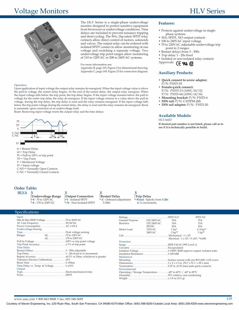
tr = Restart Delaytd = Trip DelayPI = Pull-in 105% or trip pointTP = Trip PointV = Monitored VoltageIV = Input voltageC-NO = Normally Open ContactsC-NC = Normally Closed Contacts
PITPV
C-NOC-NC
IV
Courtesy of Steven Engineering, Inc.-230 Ryan Way, South San Francisco, CA 94080-6370-Main Office: (650) 588-9200-Outside Local Area: (800) 258-9200-www.stevenengineering.com
120 www.ssac.com • 800-843-8848 • fax: 605-348-5685
Features:
• Economical single-phase brownout/under-voltage protection
• Isolated, 8A, SPDT output contacts• Protects sensitive 110 to 120VAC or 220 to
240VAC loads• Adjustable low voltage trip point• LED Indicator Approvals:
Auxilary Products:
•Quick connect to screw adaptor: P/N: P1015-18
•Female quick connect: P/N: P1015-64 (AWG 14/16)•DIN rail: P/N: C103PM (Al)•DIN rail adaptor: P/N: P1023-20
KVM SeriesVoltage Monitors
Available Models:
Line VoltageType . . . . . . . . . . . . . . . . . . . . . . . . . . . . . . . . . . . . . Single phaseInput Voltage . . . . . . . . . . . . . . . . . . . . . . . . . . . . . 110 to 120VAC or 220 to 240VACAC Line Frequency . . . . . . . . . . . . . . . . . . . . . . . . 50/60 HzPower Consumption . . . . . . . . . . . . . . . . . . . . . . . 2.5W @ 132VAC; 4.5W @ 264VACPower Off Reset Time . . . . . . . . . . . . . . . . . . . . . . < 150ms Undervoltage DetectionUndervoltage Setpoint KVM4 . . . . . . . . . 78 to 99VAC KVM6 . . . . . . . . . 156 to 199VACUndervoltage Reset Point KVM4 . . . . . . . . . Fixed at 104VAC KVM6 . . . . . . . . . Fixed at 209VACRepeatability . . . . . . . . . . . . . . . . . . . . . . . . . . . . . . ± 0.5% under fixed conditions ±1% over temperature rangeVoltage Sensing Accuracy . . . . . . . . . . . . . . . . . . ±2% at 25°COutputType . . . . . . . . . . . . . . . . . . . . . . . . . . . . . . . . . . . . . Electromechanical relayForm . . . . . . . . . . . . . . . . . . . . . . . . . . . . . . . . . . . . . SPDTRating . . . . . . . . . . . . . . . . . . . . . . . . . . . . . . . . . . . . 8A resistive @ 120VAC, 1/3 hp @ 120/240VAC
Life . . . . . . . . . . . . . . . . . . . . . . . . . . . . . . . . . . . . . . Mechanical - 1 x 10⁶; Electrical - 1x10⁵ LED Indicator . . . . . . . . . . . . . . . . . . . . . . . . . . . . . Glows green when output is energizedProtectionSurge . . . . . . . . . . . . . . . . . . . . . . . . . . . . . . . . . . . . IEEE C62.41-1991 Level ACircuitry . . . . . . . . . . . . . . . . . . . . . . . . . . . . . . . . . . EncapsulatedIsolation Voltage . . . . . . . . . . . . . . . . . . . . . . . . . . . > 1500V RMS input to outputInsulation Resistance . . . . . . . . . . . . . . . . . . . . . . . > 100 MΩ minimumMechanicalMounting . . . . . . . . . . . . . . . . . . . . . . . . . . . . . . . . . Surface mount with one #10 (M5 x 0.8) screwDimensions . . . . . . . . . . . . . . . . . . . . . . . . . . . . . . . 2 x 2 x 1.21 in. (50.8 x 50.8 x 30.7 mm)Termination . . . . . . . . . . . . . . . . . . . . . . . . . . . . . . . 0.25 in. (6.35 mm) male quick connect terminalsEnvironmentalOperating / Storage Temperature . . . . . . . . . . . . -25 to 55°C / -40 to 85°CHumidity . . . . . . . . . . . . . . . . . . . . . . . . . . . . . . . . . 95% relative, non-condensingWeight . . . . . . . . . . . . . . . . . . . . . . . . . . . . . . . . . . . 2.6 oz (74 g)
Specifications
Order Table: Undervoltage Setpoint
78 to 99VAC156 to 199VAC
Maximum Line Voltage132VAC264VAC
Part NumberKVM4KVM6
KVM4KVM6
The KVM Series is a single-phase undervoltage monitor designed to protect sensitive equipment against brownout undervoltage conditions. The compact design and encapsulated construction make the KVM an excellent choice for OEM equipment .
For more information see:Appendix B, page 165, Figure 1 for dimensional drawing.Appendix C, page 169, Figure 16 for connection diagram.
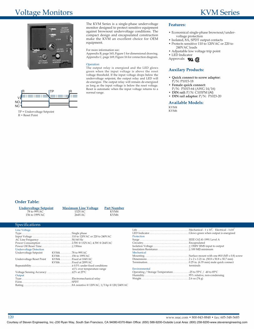
OperationThe output relay is energized and the LED glows green when the input voltage is above the reset voltage threshold. If the input voltage drops below the undervoltage setpoint, the output relay and LED will de-energize. The output relay will remain de-energized as long as the input voltage is below the reset voltage. Reset is automatic when the input voltage returns to a normal range .
TP = Undervoltage SetpointR = Reset Point
Courtesy of Steven Engineering, Inc.-230 Ryan Way, South San Francisco, CA 94080-6370-Main Office: (650) 588-9200-Outside Local Area: (800) 258-9200-www.stevenengineering.com