Embed Size (px)
Citation preview

United States Agency forInternational Development
Draft Report
USAID TRN-03-009
Stevedoring Services of AmericaBERGER/ABAM
Submitted to
Submitted by
April 2003
Umm Qasr Port Assessment

UMM QASR PORT ASSESSMENT
USAID CLIN 01-009
DRAFT REPORT
Submitted to United States Agency for International Development
Submitted by
Stevedoring Services of America BERGER/ABAM Engineers Inc.
April 2003

DRAFT UMM QASR PORT ASSESSMENT USAID CLIN 01-009
Stevedoring Services of America Page ii 21 April 2003
TABLE OF CONTENTS
EXECUTIVE SUMMARY ................................................................................................... 1
SECTION 1 – INTRODUCTION ......................................................................................... 6
SECTION 2 – FACILITIES INSPECTED ............................................................................ 8
SECTION 3 – NAVIGATION............................................................................................... 9 3.1 Physical Characteristics .......................................................................................... 9 3.1.1 Location ................................................................................................... 9 3.1.2 Port Configuration ....................................................................................... 9 3.1.3 Channel Dimensions ................................................................................... 9 3.1.4 Tides ................................................................................................... 10 3.1.5 Geology ................................................................................................... 10 3.1.6 Anchorage Areas......................................................................................... 10 3.1.7 Turning Basins ............................................................................................ 10 3.1.8 Navigation Aids ........................................................................................... 11 3.1.9 Shoaling Patterns and History..................................................................... 11 3.2 Present Condition ................................................................................................... 11 3.2.1 River Channel.............................................................................................. 11 3.2.2 Port Berths .................................................................................................. 12 3.2.3 Anchorage Areas......................................................................................... 12 3.2.4 Turning Basins ............................................................................................ 12 3.2.5 Navigation Aids ........................................................................................... 12 3.2.6 Reported Wrecks......................................................................................... 12 3.2.7 Mines ................................................................................................... 12 3.2.8 Past Dredging and Disposal Practices ........................................................ 13 3.2.9 Dredged Material Disposal Sites ................................................................. 13 3.2.10 On-Site Fleet ............................................................................................... 14 3.2.11 Hopper Dredges .......................................................................................... 14 3.2.12 Cutter-Suction Dredge................................................................................. 14 3.3 Reactivation Operational Requirements for Restoring Channel and Berthing Depths ............................................................................................... 15 3.3.1 General ................................................................................................... 15 3.3.2 Dredging Plan.............................................................................................. 15 3.3.3 Dredging Quantities..................................................................................... 16 3.3.4 Dredging Costs............................................................................................ 19 3.3.5 Material Sampling and Testing.................................................................... 19 3.3.6 Other Needs and Priorities .......................................................................... 19 3.3.7 Long-Term Needs ....................................................................................... 19 3.3.8 On-Site Fleet Activation and Testing........................................................... 20
SECTION 4 – CARGO HANDLING CAPABILITIES ........................................................... 21 4.1 Bulk Facilities ................................................................................................... 21 4.1.1 Bulk Operational Condition.......................................................................... 21 4.1.2 Bulk Berth Characteristics ........................................................................... 31
DRAFT UMM QASR PORT ASSESSMENT USAID CLIN 01-009
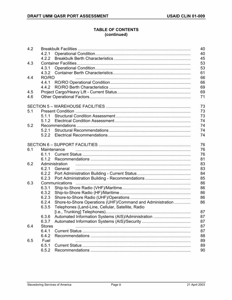
Stevedoring Services of America Page iii 21 April 2003
TABLE OF CONTENTS (continued)
4.2 Breakbulk Facilities ................................................................................................. 40 4.2.1 Operational Condition.................................................................................. 40 4.2.2 Breakbulk Berth Characteristics .................................................................. 45 4.3 Container Facilities.................................................................................................. 53 4.3.1 Operational Condition.................................................................................. 53 4.3.2 Container Berth Characteristics................................................................... 61 4.4 RO/RO ................................................................................................... 66 4.4.1 RO/RO Operational Condition..................................................................... 66 4.4.2 RO/RO Berth Characteristics ...................................................................... 69 4.5 Project Cargo/Heavy Lift - Current Status............................................................... 69 4.6 Other Operational Factors....................................................................................... 71
SECTION 5 – WAREHOUSE FACILITIES ......................................................................... 73 5.1 Present Condition ................................................................................................... 73 5.1.1 Structural Condition Assessment ................................................................ 73 5.1.2 Electrical Condition Assessment ................................................................. 74 5.2 Recommendations .................................................................................................. 74 5.2.1 Structural Recommendations ...................................................................... 74 5.2.2 Electrical Recommendations....................................................................... 74
SECTION 6 – SUPPORT FACILITIES ............................................................................... 76 6.1 Maintenance ................................................................................................... 76 6.1.1 Current Status ............................................................................................. 76 6.1.2 Recommendations ...................................................................................... 81 6.2 Administration ................................................................................................... 83 6.2.1 General ................................................................................................... 83 6.2.2 Port Administration Building - Current Status.............................................. 84 6.2.3 Port Administration Building - Recommendations ....................................... 85 6.3 Communications ................................................................................................... 86 6.3.1 Ship-to-Shore Radio (VHF)/Maritime........................................................... 86 6.3.2 Ship-to-Shore Radio (HF)/Maritime............................................................. 86 6.2.3 Shore-to-Shore Radio (UHF)/Operations .................................................... 86 6.2.4 Shore-to-Shore Operations (UHF)/Command and Administration .............. 86 6.3.5 Telephones (Land-Line, Cellular, Satellite, Radio [i.e., Trunking] Telephones)......................................................................... 87 6.3.6 Automated Information Systems (AIS)/Administration ................................ 87 6.3.7 Automated Information Systems (AIS)/Security .......................................... 87 6.4 Stores ................................................................................................... 87 6.4.1 Current Status ............................................................................................. 87 6.4.2 Recommendations ...................................................................................... 88 6.5 Fuel ................................................................................................... 89 6.5.1 Current Status ............................................................................................. 89 6.5.2 Recommendations ...................................................................................... 90

DRAFT UMM QASR PORT ASSESSMENT USAID CLIN 01-009
Stevedoring Services of America Page iv 21 April 2003
TABLE OF CONTENTS (continued)
SECTION 7 – TRANSPORTATION.................................................................................... 92 7.1 Roadways ................................................................................................... 92 7.1.1 General ................................................................................................... 92 7.1.2 “New” Port ................................................................................................... 92 7.1.3 Old Port ................................................................................................... 95 7.1.4 Grain Elevator ............................................................................................. 96 7.2 Railroads ................................................................................................... 96 7.2.1 General ................................................................................................... 96 7.2.2 New Port ................................................................................................... 97 7.2.3 Old Port ................................................................................................... 99 72.4 Grain Elevator ............................................................................................. 100 7.3 Air ................................................................................................... 100 7.3.1 General ................................................................................................... 100 7.4 Inland Waterways ................................................................................................... 100 7.4.1 General ................................................................................................... 100
SECTION 8 – UTILITIES ................................................................................................... 101 8.1 High Voltage Electrical ............................................................................................ 101 8.1.1 Iraqi National Grid Substations.................................................................... 101 8.1.2 New Port Area ............................................................................................. 101 8.1.3 Grain Facility ............................................................................................... 104 8.1.4 Old Port Area............................................................................................... 107 8.1.5 Sugar and Vegetable Oil Facility ................................................................. 108 8.1.6 Cement Facility............................................................................................ 108 8.1.7 Umm Qasr/UN Compound .......................................................................... 108 8.2 Water System ................................................................................................... 109 8.2.1 General ................................................................................................... 109 8.2.2 New Port ................................................................................................... 110 8.2.3 Old Port ................................................................................................... 114 8.2.4 Grain Elevator ............................................................................................. 116 8.3 Sanitary Sewer ................................................................................................... 119 8.3.1 Sanitary Sewer ............................................................................................ 119 8.3.2 General Recommendations......................................................................... 119 8.4 Storm Drainage ................................................................................................... 119 8.4.1 General Condition Assessment ................................................................... 119 8.4.2 General Recommendations......................................................................... 119
SECTION 9 – SAFETY, SECURITY, AND ENVIRONMENTAL ......................................... 120 9.1 Introduction ................................................................................................... 120 9.1.1 Initial Safety, Security, and Environmental Assessment Phase .................. 120 9.1.2 Port Physical Boundary ............................................................................... 120 9.1.3 Assumptions................................................................................................ 120 9.2 Facility Safety, Security, and Environmental Organization...................................... 123 9.3 Procedural Security................................................................................................. 123

DRAFT UMM QASR PORT ASSESSMENT USAID CLIN 01-009
Stevedoring Services of America Page v 21 April 2003
TABLE OF CONTENTS (continued)
9.4 Physical Security ................................................................................................... 123 9.4.1 General ................................................................................................... 123 9.4.2 Location ................................................................................................... 123 9.4.3 Physical Barriers ......................................................................................... 125 9.5 Security Detection and Alarm Systems................................................................... 127 9.6 Security Monitoring Systems................................................................................... 128 9.7 Security Identification Systems ............................................................................... 128 9.8 Electronic Access Control Systems ........................................................................ 128 9.9 Information Security ................................................................................................ 128 9.10 Classified Storage ................................................................................................... 1289.11 Communications Security ....................................................................................... 128 9.12 Tenant Customer and Contractor Security Considerations..................................... 128 9.13 Cargo Security ................................................................................................... 129 9.14 Personnel Security .................................................................................................. 129 9.15 Personnel Reliability (and “Vetting”) Program......................................................... 129 9.16 Security Guard Forces ............................................................................................ 129 9.17 Canine (K-9) Program ............................................................................................. 129 9.18 Harbor Surveillance and Waterside Security........................................................... 129 9.19 Hazardous Materials (HAZMAT) and Dangerous Goods (DG) Handling, Record Keeping and Storage.................................................................. 131 9.20 HAZMAT and DG Disposal ..................................................................................... 131 9.21 Emergency Response............................................................................................. 131 9.22 Environmental Sensitivity ........................................................................................ 131 9.23 Safety, Security, and Environmental Training ......................................................... 131 9.24 Conclusions ................................................................................................... 131 9.24.1 Port Physical Boundary ............................................................................... 132 9.24.2 Assumptions................................................................................................ 132 9.24.3 Facility Security Assessment....................................................................... 132 9.24.4 Budget ................................................................................................... 132
SECTION 10 – MARINE OPERATIONS ............................................................................ 133 10.1 Marine Operations Department............................................................................... 133 10.2 Qualified Marine Pilots ............................................................................................ 133 10.3 Military and Civil Port Controls, Communications, and Command Systems ........... 133
SECTION 11 – CONCLUSIONS......................................................................................... 134
APPENDIXES
A WAREHOUSE INVENTORY B MOBILE EQUIPMENT SURVEY C OLD PORT MOBILE CRANE SURVEY

DRAFT UMM QASR PORT ASSESSMENT USAID CLIN 01-009
Stevedoring Services of America Page 1 21 April 2003
EXECUTIVE SUMMARY
The two-week study of the Port of Umm Qasr by the Stevedoring Services of America (SSA) Assessment Team is now complete.
The Draft Port Assessment, being a report on the first phase of three phases comprising the United States Agency for International Development (USAID) /SSA contract is now hereunder presented for review and comment by USAID.
The second phase – CLIN 002 Planning Implementation of Port Management Improvements is now being undertaken and will be submitted to USAID for review, comment, and approval within one week of today.
OPERATIONAL SECURITY
One Port Integrity
Umm Qasr has been frequently referred to by its component parts, acknowledging its natural development from an “old” port, to a “new” port, a grain-handling facility, a cement-handling facility, etc. With this, SSA began to observe a trend to consider the Port as separate facilities within a geographic area. The perception that the Port is a few ports or activities will multiply the task of securing the area.
In addition, due to the fact that the Port has been historically underutilized (some estimates place the Port’s efficiency at 40 percent of its potential), and the fact that the Coalition Forces have cleared the Port of all remaining previous activity; there are ample resources (such as warehouses, buildings, and land) available to settle into. If we do not unilaterally control (or carefully allocate) the available resources (by analyzing cargo and Port safety traffic patterns and conducting tenant activity background investigations), we will compromise the integrity (safety and security) of the Port’s activities.
The assessment team has observed that some contractors and non-governmental agencies are “settling” into available Port facilities (for example, making habitability modifications to existing warehouses). We are confident that these contractors and activities have been initially screened and are serving an essential purpose; but we also wish to ensure that all of these tenants understand that their participation and/or location may be transitory and that SSA must evaluate the Port’s space utilization and resource integration in the overall management of the Port.
SSA strongly encourages the consideration of the Port of Umm Qasr as a composite unit operated by one entity and under the management and jurisdiction of one Port Authority. The Port Authority will establish the working rules to accomplish the Port’s missions and will manage the use and allocation of the Port’s real estate and resources.
In order to promote the concept of this “One Port” umbrella management, SSA will discuss the establishment of a defined Port Physical Boundary in this assessment’s Security section (Section 9).

DRAFT UMM QASR PORT ASSESSMENT USAID CLIN 01-009
Stevedoring Services of America Page 2 21 April 2003
Navigation
Navigation depths from the Persian Gulf to the Port of Umm Qasr and along the berths at the Port facilities currently preclude the safe transit and docking of 50,000-metric-ton vessels. The approach channel has draft limitations from isolated shoals ranging from 7 to 10 meters, Celestial Low Water, (CLW). Average depths for the 50-nautical mile channel, (from Buoy 1), are in the 11-meter range, CLW.
All berths in the “old” and “new” port have limited depths alongside ranging from 2 to 7 meters, CLW, at the berth. The approach channel at the “old” port has depths in the 12-meter range. The approach channel to and within the “new” port has depths in the 7-meter range, with the exception of the formation of a natural spit across the entrance to the “new” port that limits depths to 4 or 5 meters, CLW.
On-site dredges are small in capacity. The four hopper dredges are in very poor condition. One of the two cutter-suction dredges is in poor condition and the other appears to be operable, but has only a small amount pipeline available. Crew staffing and reliability for a 24/6 or 7 work schedule is doubtful for more than training and limited berth and river channel maintenance.
A large medium hopper dredge for the river approach channel and a large cutter-suction dredge for the Port should be contracted to open the Port for service to vessels larger than 25,000 mt.
A number of reported wrecks exist in or near the river channel and at some of the berths in both Port areas. A wreck investigation and removal program to coincide with channel re-dredging is required.
A proposed dredging plan is provided for a scenario that would open the Port to safe service by larger vessels as early as possible.
Dredging quantities to provide full berthing of 25,000 ton to 50,000 ton vessels at five selected berths will be about 3,000,000 cubic meters in the Port area and about 8,200,000 cubic meters to provide a reduced width 120-meter by 12.5-meter approach channel from Buoy 1 at the Pilot Boat Station in the Persian Gulf. Of the channel dredging volume, 5,200,000 cubic meters have been delegated as Priority 2 dredging.
Power
The “new” port and “old” port, 11KV primary power systems, transformers, and switchgear are 20+ and 40+ years old. These systems have not been properly maintained or upgraded since their original installation. These systems and equipment need to be replaced in their entirety for safe and reliable operation of the Port Facilities.
The grain elevator, 33KV and 3.3KV primary power systems, transformers, and switchgear are 20+ years old. With maintenance and testing, these systems can be operational but need to be scheduled for replacement.
The grain elevator and grain evacuator secondary electrical distribution systems, transformers, switchgear, and panels have been improperly maintained and require total replacement for safe and reliable operation of the grain elevator and grain evacuators.

DRAFT UMM QASR PORT ASSESSMENT USAID CLIN 01-009
Stevedoring Services of America Page 3 21 April 2003
Site Lighting
Control of site lighting is at individual light towers. Over 50 percent of the 1000w high-pressure sodium-light fixtures are missing from the towers. Site lighting with the exception of the towers needs to be totally replaced and new lighting controls provided.
Site Communications
The existing communications throughout the entire Port area is nonfunctional and needs to be replaced entirely with new and modern systems.
Water
The existing fresh water system throughout the Port is non-operational. Portable generators will be required to supply power to the pump stations. All water-pumping equipment and electronic controls at each of the pump stations will need to be tested and repaired. In the interim, potable water will need to be either trucked or produced. Production would entail the use of a portable reverse osmosis treatment system – similar to that currently in use by the Coalition Forces.
Sanitation
The sanitary sewer infrastructure is presently inoperable. Portable toilets that are periodically pumped out and cleaned will be required throughout the Port until a permanent sanitary sewer masterplan is developed.
Cargo Ops
Umm Qasr Port possesses more than adequate berthing space on the face of it (over 4 km in length) and ample storage space: in excess of 160,000 square meters of covered storage and 800,000 square meters of open storage in the “old” and “new” ports combined. There is, however, a definite shortage of adequate and useable equipment in working order.
It will be most advantageous from all aspects – security, administration, labor, maintenance, and operations – to consolidate all cargo handling in the area of “new” port; and this is the goal to strive for. However, bulk grain vessels will need to be handled at the location of the working equipment, i.e., “old” port.
Grain Silo (Berth 10)
The elevator facility was constructed in the early 1980s and at that time would have been considered state-of-the-art. Since construction the elevator has suffered from years of neglect and improper maintenance. Accepting that emergency measures could be undertaken that would enable the large storage capacity of the silos to be utilized, the necessary time and capital could then be allocated to refurbish the entire grain facility complex. Only in this way can a safe, productive, and reliable operation of this facility be assured.
Bulk Food Grains (Berths 1 and 2)
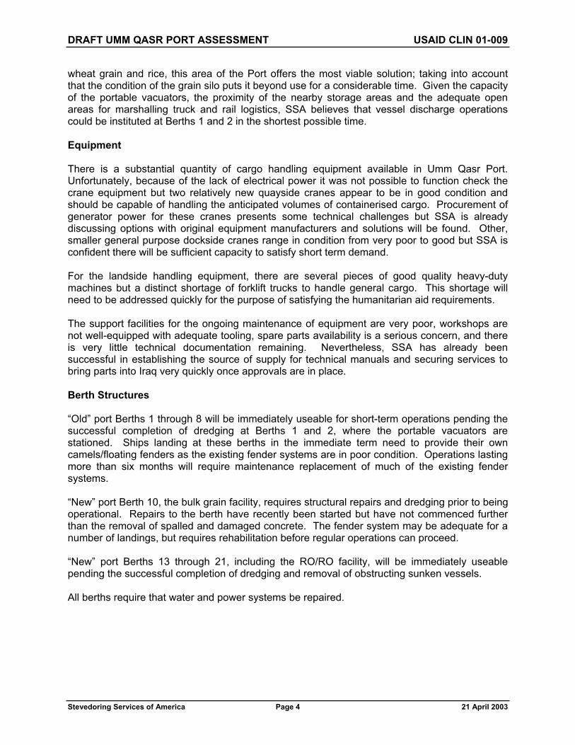
Taking into consideration the severe limitations on vessel draught that exists at the Port and in its near approaches and the pressing need for timely arrival of humanitarian aid in the form of
DRAFT UMM QASR PORT ASSESSMENT USAID CLIN 01-009
Stevedoring Services of America Page 4 21 April 2003
wheat grain and rice, this area of the Port offers the most viable solution; taking into account that the condition of the grain silo puts it beyond use for a considerable time. Given the capacity of the portable vacuators, the proximity of the nearby storage areas and the adequate open areas for marshalling truck and rail logistics, SSA believes that vessel discharge operations could be instituted at Berths 1 and 2 in the shortest possible time.
Equipment
There is a substantial quantity of cargo handling equipment available in Umm Qasr Port. Unfortunately, because of the lack of electrical power it was not possible to function check the crane equipment but two relatively new quayside cranes appear to be in good condition and should be capable of handling the anticipated volumes of containerised cargo. Procurement of generator power for these cranes presents some technical challenges but SSA is already discussing options with original equipment manufacturers and solutions will be found. Other, smaller general purpose dockside cranes range in condition from very poor to good but SSA is confident there will be sufficient capacity to satisfy short term demand.
For the landside handling equipment, there are several pieces of good quality heavy-duty machines but a distinct shortage of forklift trucks to handle general cargo. This shortage will need to be addressed quickly for the purpose of satisfying the humanitarian aid requirements.
The support facilities for the ongoing maintenance of equipment are very poor, workshops are not well-equipped with adequate tooling, spare parts availability is a serious concern, and there is very little technical documentation remaining. Nevertheless, SSA has already been successful in establishing the source of supply for technical manuals and securing services to bring parts into Iraq very quickly once approvals are in place.
Berth Structures
“Old” port Berths 1 through 8 will be immediately useable for short-term operations pending the successful completion of dredging at Berths 1 and 2, where the portable vacuators are stationed. Ships landing at these berths in the immediate term need to provide their own camels/floating fenders as the existing fender systems are in poor condition. Operations lasting more than six months will require maintenance replacement of much of the existing fender systems.
“New” port Berth 10, the bulk grain facility, requires structural repairs and dredging prior to being operational. Repairs to the berth have recently been started but have not commenced further than the removal of spalled and damaged concrete. The fender system may be adequate for a number of landings, but requires rehabilitation before regular operations can proceed.
“New” port Berths 13 through 21, including the RO/RO facility, will be immediately useable pending the successful completion of dredging and removal of obstructing sunken vessels.
All berths require that water and power systems be repaired.

DRAFT UMM QASR PORT ASSESSMENT USAID CLIN 01-009
Stevedoring Services of America Page 5 21 April 2003
It is strongly recommended that a thorough underwater inspection of all berths be completed by a licensed engineer/diver with a structural engineering background – not a typical commercial diver – to verify structural conditions. Neither coalition forces nor the SSA group performed an underwater structural inspection. Given the state of maintenance on the rest of the facilities, it is unlikely that one has ever been accomplished.
Transportation
Road and rail service to Basrah is in serviceable condition. Normal maintenance is required. The nearest serviceable airport is Basrah International.
Costs
Priority 1 designated program costs, or those repairs deemed absolutely necessary to enable the shipment of humanitarian aid safely, are estimated to be US$90,565,000. Priority 2 designated program costs, or those repairs deemed necessary to provide continuing Port operations, are estimated to be US$74,267,000.

DRAFT UMM QASR PORT ASSESSMENT USAID CLIN 01-009
Stevedoring Services of America Page 6 21 April 2003
SECTION 1.0 — INTRODUCTION
Stevedoring Services of America (SSA) is pleased to submit this report to the United States Agency for International Development (USAID) in accordance with USAID Contract CLIN-01-009 for the preparation of a port management assessment. This draft report is being submitted to the designated Cognizant Technical Officer (CTO) at USAID, Mr. Ross Wherry. USAID shall provide verbal and written comments to SSA within five working days of receipt of this draft port assessment. USAID’s comments and SSA’s responses will be included in SSA’s final report. Concurrent with the review of this draft report, SSA is proceeding to plan the implementation of USAID-approved port improvements in a work plan in accordance with USAID Contract CLIN-02-009.
The objective of this assessment is to evaluate the Umm Qasr Port facility for the import of USAID provided materials and supplies, and other cargoes including urgent food assistance and materials for reconstruction and rehabilitation. Additionally, the assessment identifies Port-imposed constraints to be addressed in the Phase 2, Port Improvement Implementation Plan, so that during Phase 3, Port Operations, an adequate flow of through shipments will occur.
The SSA assessment team, headed by Capt. T. Fergus Moran, arrived at USAID’s offices in Kuwait City, Kuwait on 7 April 2003. The 14-member assessment team was comprised of stevedoring operation specialists and port design, construction, and operation engineers.
As Iraq’s only deep-water seaport, the Port at Umm
Qasr is a critical link towards the import of life-providing assistance being provided to the people of Iraq. Iraq, located at the northwest end of the Persian Gulf, see Figure 1.0-1, has only a 53-kilometers-long coastline. Umm Qasr is located near the southern edge of Iraq’s Gulf shoreline along the river Khawr Az Zubayr (see Figure 1.0-2) near the Kuwait border. The Port of Umm
Figure 1.0-1 Middle East from CIA Online Publications.

DRAFT UMM QASR PORT ASSESSMENT USAID CLIN 01-009
Stevedoring Services of America Page 7 21 April 2003
Qasr is within the limits of the Port of Basrah and the two are connected by inland waterway, roads, and rail.
The Port facility at Umm Qasr is comprised of four different walled compounds, see Figure 1.0-3. The two principle areas are referred to as the “old” port and the “new” port. The “old” port area is located along the main channel of the river Khawr Az Zubayr. The “new” port area is located inside a manmade basin off the Khawr Az Zubayr and is located to the north of the “old” port. Between the two port areas are two separate fenced facilities, one for bulk handling of grain and the other for the bulk handling of sugar and vegetable oil, see Figure 1.0-3.
Our assessment, in support of humanitarian aid and reconstruction assistance to the people of Iraq, was greatly aided by the support and assistance of the Commanding Officer, 17th Port and Maritime Regiment, Royal Logistics Core, RLC), Lieut. Col. Paul Ash and his staff including: Major John Soar, Major John Taylor, and Captain Peter Smith.
Figure 1.0-2 Iraq from CIA Online Publications.
Figure 1.0-3 Village and Port of Umm Qasr, Excerpt from B.A. Chart 1238.

DRAFT UMM QASR PORT ASSESSMENT USAID CLIN 01-009
Stevedoring Services of America Page 8 21 April 2003
2.0 — FACILITIES INSPECTED
The following facilities within the “old” port were inspected during the preparation of this report:
Berths 1, 2, 5, 6, 7, and 8 Warehouse/Storage Buildings Fire Station Pump Station Rail Yards Generator Building Transformer/Switchgear Building Gate Building Scales
The following facilities within the “new” port were inspected during the preparation of this report:
Berth 10, Bulk Grain Unloading Berth Grain Facility Silos and Associated Appurtenance Structures Berths 13 to 21 Main Administration Building Warehouse/Storage Buildings Site Communication Buildings Gate Entry Building Scale Houses Fire Station Pump Station Water Tower Rail Yards Lavatory Buildings High-Voltage Electrical System Transformer/Switchgear Buildings Backup Generator Building Diked Disposal Area across Waterway from Berths 14 to 18
The following facilities at and near the Port were not inspected during the preparation of this report:
“Old” Port Berths 3,and 4, (Dedicated Sulfur) “Old” Port Berth 9 (Dedicated Cement) “New” Port Berth 11 (Dedicated Sugar/Vegetable Oil) Water Tower and Treatment Facility in the Village of Umm Qasr Other facilities outside of secured and fenced area of the Port

DRAFT UMM QASR PORT ASSESSMENT USAID CLIN 01-009
Stevedoring Services of America Page 9 21 April 2003
SECTION 3.0 — NAVIGATION
3.1 PHYSICAL CHARACTERISTICS
3.1.1 Location
The Port of Umm Qasr is located about 50 nautical miles upstream from Buoy 1 at the entrance into the Persian Gulf of the Khawr Az Zubar River on the west bank. The Khawr Zubar and Khawr Abddullah meet at the Port to form the Khawr Az Zubayr. The approximate position of the Port is 30 degrees, 02 minutes N, 47 degrees, 57 minutes E.
The prevailing winds are mainly northwesterly and occasionally reach Beaufort force 6 to 7. Sea surface temperatures range from 17 degrees centigrade in winter to 32 degrees centigrade in the summer. During July and August, air temperatures reach 48 to 49 degrees centigrade with clear skies and low relative humidity of about 17 percent.
3.1.2 Port Configuration
The “old” port is located along the west bank parallel to the waterway that trends north and south. The “new” port is immediately upstream and in an excavated cut angling northwest from the waterway.
All berths, including 1 through 9 in the “old” port, the transitional Berths 10 and 11, and Berths 12 through 21 in the “new” port are situated on wharves parallel to the waterways. Berths 1 through 9 extend about 1 nautical mile along the waterway bank. Berths 12 through 21 extend about 2 nautical miles into a cut channel from the entrance area near Berths 10 and 11.
3.1.3 Channel Dimensions
The Port and approaches to Umm Qasr are covered by British Admiralty Charts 1235 and 1238, and by U.S. National Imagery and Mapping Agency chart 62437. A hydrographic survey underway by the HMS Roebuck will result in updated Admiralty Charts.
The navigation approach channel through the Khawr Az Zubar river channel is about 244 meters wide for the first 35 nautical miles from the Pilot Boat Station and then expands to about 305 meters wide for the remaining 15 nautical miles to the “old” port. The most recent information about design depths is British Admiralty Chart 1238 that indicates the first 35 nautical miles of the river channel from the Pilot Boat Station were dredged to 12.5 meters and the remaining 15 nautical miles upstream were dredged to 13.2 meters, in 1990.
The approach channel along the “old” port is generally about 488 meters wide with about 183 meters of separation from the average berth face to the near channel edge.
The “new” port cut beginning near Berths 10 and 11, is about 305 meters wide, with an expansion to about 488 meters in width from Berth 17 upstream. Based upon advance information from the HMS Roebuck surveys, it appears the entrance to the “new” port has been maintained only about 150 meters wide. The only information available about design depths for the Port berths are the notations on Admiralty Chart 1238 that indicate the “old” port berths were dredged to 13.2 meters and the “new” port cut was dredged to 12.5 meters in 1990.
DRAFT UMM QASR PORT ASSESSMENT USAID CLIN 01-009
Stevedoring Services of America Page 10 21 April 2003
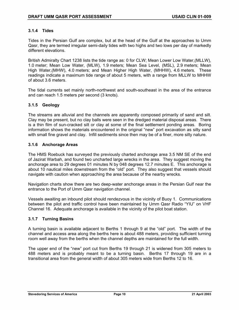
3.1.4 Tides
Tides in the Persian Gulf are complex, but at the head of the Gulf at the approaches to Umm Qasr, they are termed irregular semi-daily tides with two highs and two lows per day of markedly different elevations.
British Admiralty Chart 1238 lists the tide range as: 0 for CLW; Mean Lower Low Water,(MLLW), 1.0 meter; Mean Low Water, (MLW), 1.9 meters; Mean Sea Level, (MSL), 2.9 meters; Mean High Water,(MHW), 4.0 meters; and Mean Higher High Water, (MHHW), 4.6 meters. These readings indicate a maximum tide range of about 5 meters, with a range from MLLW to MHHW of about 3.6 meters.
The tidal currents set mainly north-northwest and south-southeast in the area of the entrance and can reach 1.5 meters per second (3 knots).
3.1.5 Geology
The streams are alluvial and the channels are apparently composed primarily of sand and silt. Clay may be present, but no clay balls were seen in the dredged material disposal areas. There is a thin film of sun-cracked silt or clay at some of the final settlement ponding areas. Boring information shows the materials encountered in the original “new” port excavation as silty sand with small fine gravel and clay. Infill sediments since then may be of a finer, more silty nature.
3.1.6 Anchorage Areas
The HMS Roebuck has surveyed the previously charted anchorage area 3.5 NM SE of the end of Jazirat Warbah, and found two uncharted large wrecks in the area. They suggest moving the anchorage area to 29 degrees 01 minutes N by 048 degrees 12.7 minutes E. This anchorage is about 10 nautical miles downstream from the “old” port. They also suggest that vessels should navigate with caution when approaching the area because of the nearby wrecks.
Navigation charts show there are two deep-water anchorage areas in the Persian Gulf near the entrance to the Port of Umm Qasr navigation channel.
Vessels awaiting an inbound pilot should rendezvous in the vicinity of Buoy 1. Communications between the pilot and traffic control have been maintained by Umm Qasr Radio “YIU” on VHF Channel 16. Adequate anchorage is available in the vicinity of the pilot boat station.
3.1.7 Turning Basins
A turning basin is available adjacent to Berths 1 through 9 at the “old” port. The width of the channel and access area along the berths here is about 488 meters, providing sufficient turning room well away from the berths when the channel depths are maintained for the full width.
The upper end of the “new” port cut from Berths 19 through 21 is widened from 305 meters to 488 meters and is probably meant to be a turning basin. Berths 17 through 19 are in a transitional area from the general width of about 305 meters wide from Berths 12 to 16.

DRAFT UMM QASR PORT ASSESSMENT USAID CLIN 01-009
Stevedoring Services of America Page 11 21 April 2003
3.1.8 Navigation Aids
The British Military report that existing buoys are old, some are missing, and many are out of place. The existing system does mark most of the river channel, but none are lighted. The U.S. Coast Guard (USCG) Buoy Tender Walnut will be installing mostly new lighted buoys starting about 17 April 2003.
3.1.9 Shoaling Patterns and History
Umm Qasr Port is adjacent to an embayment at the north end of the Persian Gulf. The embayment also is the estuary for several small rivers that drain a wetland area north of the Port. In addition, a canal was cut connecting the rivers to the Shaat al Arab waterway at Basra so that additional flow is added from the Tigris-Euphrates River system. Even so, the dominant flow pattern in the Port area is tidal with currents of up to 4 knots, (2.1m/s).
The channel downstream is sinuous and follows the typical pattern of sediments deposited in bar formations on the insides of the bends. Additionally, as the inlet widens downstream and current velocities are reduced, cross channel bars are deposited that are shaped by upstream and downstream tidal currents into typical ebb-flood pairs.
The channel bends and the cross channel bars are areas where maintenance dredging will be focused. In the Port, deposition occurs along both sides in the “old” port, requiring maintenance dredging along the berths and along the opposite shore to maintain the channel width for the turning basin.
The “new” port is a cut more than 4 kilometers long and some 300 meters wide and widens to nearly 490 meters at its head. Suspended sediments entering the cut on the incoming tide settle out in the quiet water primarily at the sides creating the need for maintenance dredging at the berths. The eastern side of the cut is shoaled extensively. The source of the shoaling was probably from uncontrolled runoff originating from the undiked dredged material disposal on adjacent upland. Recently constructed dikes should eliminate this shoaling source. Removal of the shoal is not a requirement at this time as adequate channel widths will be provided for the near future in the recommended dredging program.
A spit grows from river channel sediments at the entrance of the “new” port cut. This spit requires regular maintenance dredging.
Nearly continuous maintenance dredging of the berths and approach channel from the Pilot Boat Station will be required to keep the Port viable. The existence of a large number of dredge vessels in various states of functionality appear to confirm that requirement.
3.2 PRESENT CONDITION
3.2.1 River Channel
Average channel depths throughout the 50-nautical-mile channel are about 11 to 11.5 meters. Actual limiting shoals above 13 meters occur in the upper 44 nautical miles of the channel and begin about 6 nautical miles above entrance Buoy 1. The least soundings are in the 7-meter range but are isolated to the upper reaches near the Port. The least soundings in the lower river channel are in the 8-meter range at several isolated locations.

DRAFT UMM QASR PORT ASSESSMENT USAID CLIN 01-009
Stevedoring Services of America Page 12 21 April 2003
3.2.2 Port Berths
Shoals along the berth areas at the “old” port are 70 to 80 meters in width and taper from a least sounding of about 8 or 9 meters at the berth face to an average 13-meter depth in the center portion of the channel. Shoals along the transitional Berths 10 and 11 taper from a least sounding of about 2 meters to about 7 meters in the channel. The entrance to the “new” port berths, including Berths 10 and 11, has a maximum depth of only about 5 meters. Shoals along the “new” port berths range from least depths of about 3 or 4 meters along Berths 12 to 15, to 7 to 8 meters at Berths 20 and 21, and taper to the current interior depths of about 7 meters.
Historical arrival drafts in recent years were limited to a maximum of about 11 meters. These vessels were routinely grounded at lows tides at the berth faces. It is almost certain the tides played an important role in the passage of arriving fully loaded vessels.
3.2.3 Anchorage Areas
No soundings are available for anchorage in the river channel described by the HMS Roebuck. Those depths are anticipated be published in the new charts under preparation. The anchorage areas in the Persian Gulf are stable and are shown on existing charts as exceeding at least 20 meter depths.
3.2.4 Turning Basins
The turning basin along the reach adjacent to “old” port Berths 1 to 9, has depths of about 12 meters from about 80 meters outward from the berth faces across the entire center channel to about 100 meters from the opposite channel limits.
The turning basin at the upper end of the “new” port cut has depths of mostly in the 7-meter range in the central portion of the cut area.
3.2.5 Navigation Aids
As noted above, the navigation aid system is in a poor and nearly unusable state and has no lighting. It is scheduled to be rebuilt this month by the USCG.
3.2.6 Reported Wrecks
The HMS Roebuck noted and charted at least 30 wrecks from the Pilot Boat Station to the Port of Umm Qasr. It is anticipated they will be noted on the soon to be published new Admiralty Charts for the area.
Older charts show wrecks at Berths 13, 15, 17 and 18 in the “new” port, at Berth 1 in the “old” port, and at numerous locations in or near the approach channel.
3.2.7 Mines
The US Navy has swept an area about 200 meters wide on each side of the approach channels and the areas adjacent to the berths in the “old” and “new” ports. Sweeping methods included energy, noise, and divers with dolphins accomplished by helicopter, ship, and small surface craft. They are currently expanding the swept area to about 600 meters on each side of the channel centerline, which should sufficiently cover potential hopper dredge disposal sites.

DRAFT UMM QASR PORT ASSESSMENT USAID CLIN 01-009
Stevedoring Services of America Page 13 21 April 2003
Elements of the British Military that are clearing the Port area for reactivation indicate that there is no land mine danger for the Port and immediately surrounding property, including the previously used dredged material disposal areas.
3.2.8 Past Dredging and Disposal Practices
Both cutter-suction and hopper dredge plants have been utilized at the Port. Former Port operators indicate that a barge-mounted clamshell crane serviced by three self-propelled dump barges was also utilized. The clam and one dump barge are reported to have sunk. The remaining two dump barges have their hoppers welded shut and were being used as fuel and lube lighters.
The small cutter-suction dredges were almost certainly utilized for maintaining depths along the berths and in the anchorage areas and turning basins. The naturally recurring spit at the entrance to the “new” port cut was probably dredged by a cutter-suction operation.
The approach channel was primarily maintained by hopper dredge.
There are sizeable upland dredged material disposal areas nearby, opposite both the “old” and “new” ports. A large estuary area behind Berths 13 to 16 has also been utilized as a cutter-suction dredge disposal site. Dike and spillway construction and maintenance do not appear to be a high priority, with some dredged materials finding their way back to the Port waters.
The British Military indicate that interviews with some of the few available former Port workers reveal that some of the cutter-suction dredge materials were simply sidecast in the river channel opposite or downstream of the “old” port. This was because of the lack of or poor condition of discharge pipeline.
Hopper dredged disposal was reported to be just downstream of the work areas. There does not appear to have been any consistent effort to haul the dredged materials any distance to insure their non-return to the shoaling locations.
3.2.9 Dredged Material Disposal Sites
For the “old” port reach, there is a diked disposal area located on the island immediately opposite the Port. This island has been utilized in the past. Some improvements to the retaining dikes and spillways may be required.
For the “new” port, the uplands to the opposite side of the waterway have been used in the past as dredged material disposal sites. A large new site encompassing about 60 hectares, located at the waters edge within easy reach of the dredging areas, has had new dikes about 3 to 4 meters in height constructed and appears nearly ready for use, except for spillway construction. The estimated capacity of these newly diked disposal areas is about 2 million cubic meters.
The recent hydrographic surveys by the HMS Roebuck covered a continuous swath about 800 meters wide along the approach channel. Bottom depths remain in excess of 10 meters throughout most of the surveyed area and indicate that a medium hopper dredge plant could operate and dispose of dredged materials a sufficient distance from the navigation channel.

DRAFT UMM QASR PORT ASSESSMENT USAID CLIN 01-009
Stevedoring Services of America Page 14 21 April 2003
Dredge operators should be required to determine from the Military the actual area swept for mines and further explore the depths outside the surveyed area so that the dredged materials could be deposited as far from the channel as safely possible.
3.2.10 On-Site Fleet
A listing provided by the United States Agency for International Development (USAID) shows an impressive array of historical dredge and attendant plant existing, or formerly existing in the area. The list was based upon previous United Nations reports. Much of the equipment listed could not be found by the British Military in their reactivation investigations. There is some speculation that some of the more viable equipment may have been relocated upstream to the military port at Az Zubar, just prior to the war. That will be confirmed or clarified during the coming weeks as the British Military operations migrate upstream to include that port.
The reports do indicate only a small fraction of the listed equipment was operable at any given time, however.
3.2.11 Hopper Dredges
There appears to be only one or two old hopper dredges reasonably available for reactivation for use in the Port and approach channel area, see Photo 3.2.11-1. The British Military are attempting to repair and restart the dredges and man them with local workers supervised at least temporarily by the British Military. If the dredges have been unused for some time and were poorly maintained, as is apparent, reactivation on a reliable basis may be impractical without major overhaul. Retraining a local crew, especially replacing the officers, will take considerable time.
3.2.12 Cutter-Suction Dredge
One medium cutter-suction dredge of about 500 mm discharge line, see Photo 3.2.12-1, is in reasonable condition for reactivation. This dredge currently has a very short discharge pipeline with a nozzle welded on to provide the minimum required centrifugal pump back pressure and to spread the dredged materials as far as possible without longer lines available. Another smaller cutter-suction is on site, but has not been evaluated fully at this time. The locals have indicated it was scheduled to be placed in the on-site dry dock for needed repairs. The unavailability of
Photo 3.2.11-1 The Hopper Dredge Alzubair Dredging at the Grain Terminal.

DRAFT UMM QASR PORT ASSESSMENT USAID CLIN 01-009
Stevedoring Services of America Page 15 21 April 2003
useable discharge pipeline for either dredge appears to be a serious problem, and the effective use of the dredges may be impaired.
The British Military have succeeded in placing a skeleton local crew, supervised by their officers, on the larger cutter-suction dredge and are attempting to work it at the present time. However, the small capacity of the dredge and the probability that continuous operation from a repair and crew standpoint is not viable raises serious doubts about its potential contribution for harbor maintenance. Lack of viable discharge pipeline also prevents the dredged materials from being placed in a neutral disposal location.
3.3 REACTIVATION OPERATIONAL REQUIREMENTS FOR RESTORING CHANNEL AND BERTHING DEPTHS
3.3.1 General
The current criteria for reactivation of the berths at both the “old” and “new” ports is to provide transit and berthing depths for vessels of approximately 50,000 tons at “old” port Berths 1 and 2, the grain terminal, Berth 10, and Berths 20 and 21, in the “new” port. A 50,000-ton vessel has an average draft of about 11 meters. Providing a minimum keel clearance of about 0.5 meter and advanced maintenance dredging of about 1 meter will require a restored dredged depth of about 12.5 meters, for full- and long-term vessel access. The number of documented wrecks in the area will require a program to investigate and remove many of them.
3.3.2 Dredging Plan
Depths are to be provided at Berths 1 and 2 as soon as practicable. Berth 10 will be the next priority followed by Berths 20 and 21. This plan follows the schedule that has been developed for reactivation of the receiving facilities at the ports.
To provide depths at the berths, a large cutter-suction dredge should be contracted. Utilization of a large contract cutter-suction dredge will insure a continuous and viable dredging program, expedite the removal of the restrictive shoaling and enable placement of the dredged materials on uplands well away from the navigation channel areas. A large dredge will also enable more rapid follow-on opening of additional berths. To provide for an early opening of the channel for the larger draft vessels, a phased approach by medium or large hopper dredge plant is recommended. A reduced channel width to about 120 meters for the initial dredging would also be recommended. This reduced width channel would be used primarily by incoming vessels. Outgoing vessels would use any portion of the channel not subject to inbound vessels. Hopper
Photo 3.2.12-1 Cutter Suction Dredge.

DRAFT UMM QASR PORT ASSESSMENT USAID CLIN 01-009
Stevedoring Services of America Page 16 21 April 2003
dredging enables a layered approach to depth restoration that opens the full length of the channel more rapidly to ever increasing drafts. The channel requires only a minor amount of isolated shoal removal to provide continuous minimum depths of 11.5 meters or greater.
Phase 1 dredging operations could be directed to eliminating the shoals above the 11.5-meter average depth. An 11.5-meter channel would provide safe transit by most 50,000-ton vessels at most tide stages. But limiting the dredge depth to 11.5 meters does not provide a long-term solution, as there would be no advance maintenance depths to absorb continued shoaling.
Phase 2 dredging would be to deepen the channel to the recommended advance maintenance depths of about 12.5 meters. Phase 2 could be accomplished in two increments. The first increment would be to dredge only the upper 22 nautical miles of the reduced width channel to the full 12.5-meter depths and the second increment would be to complete the 12.5-meter channel to daylight downstream. This scenario would expedite early transit of the channel by vessels larger than 50,000 tons utilizing the tides for the lower portion.
Phase 3 would be to continue to widen the channel depths to previously utilized dimensions.
Hydrographic surveys from the HMS Roebuck indicate that sufficient depths exist alongside the channel to enable short disposal runs by hopper plant. The dredge should be required to dispose of the dredged materials as far as safely possible from the channel limits.
3.3.3 Dredging Quantities
Estimated monthly production rates for a large cutter-suction dredge or a medium hopper dredge can be up to one million cubic meters.
“Old” port Berths 1 and 2 would be dredged to 12.5 meters. The estimated quantity for these berths and the first materials to be removed in renewed maintenance dredging program is about 60,000 cubic meters. Berth 10 would be dredged to 13.5 meters. The estimated quantity for restoring the local access channel to the Berth to 12.5 meters and for dredging the berth itself is about 1,240,000 cubic meters. Berths 20 and 21 would be dredged to 12.5 meters. Access to these berths would require the dredging of a 122-meter access channel through the entrance to the “new” port and along the length of Berths 12 through 19. A 305-meter-square turning basin adjacent to Berths 20 and 21 would also be dredged. The total additional estimated quantity from Berth 10 to Berths 20 and 21, including the turning basin, is 1,700,000 cubic meters. The location of the access channel, the turning basin, the berth dredging, and the upland disposal area are illustrated on Figure 3-1.
For the 50 nautical miles of the approach channel, the quantities to provide the first phase channel to 11.5 meters to a width of about 122 meters is about 3 million cubic meters. The additional quantity to provide the second phase, Increment 1, a 12.5-meter by 122-meter channel for the 25 nautical miles nearest the Port, would be about 1.3 million cubic meters. The additional quantity to provide for the second phase, Increment 2, a 12.5-meter by 122-meter channel for the lower 25 nautical miles to Buoy 1, would be about 3.8 million cubic meters. In summary, the total estimated quantity to provide a 12.5-meter by 122-meter channel from the Pilot Boat Station to the Port is about 8.2 million cubic meters. The total quantity to provide for Phase 3, a 12.5-meter, full-width channel for the 50 nautical miles is about 18 million cubic meters.

N
Umm Qasr Port Assessment: Dredge Plan - Figure 3.1
* Not to scale, modified to fit sheetIRAQKUWAIT
IRAQKUWAIT
488x50x12.5 Meterat Berths 20, 21
488x50x12.5 Meterat Berths 1 and 2
305 x50x13.5 Meterat Berth 10
Reported Wrecksat Berths 13, 15, 18
Reported Wreck
305 x 305Turning Basin
Existing NewDiked Disposal Sites60± Hectars
122 x 12.5 Meter Channel
KHAWR
AZZUBAYR
KHAWR
AZZUBAYR

DRAFT UMM QASR PORT ASSESSMENT USAID CLIN 01-009
Stevedoring Services of America Page 18 21 April 2003
The quantities are based on rough calculations from preliminary data available from the recent HMS Roebuck hydrographic surveying efforts, and will require further analysis when more detailed hydrographic survey data is available.
Figure 3-2 illustrates various options and the applicable estimated dredging quantities for reactivating the Port. The graph indicates the approximate volumes in millions of cubic meters required to be dredged to achieve a range of depths from 10.5 to 13.5 meters below the datum at various locations. The legend summarizes the plotted points and curves. The present channel is 244 meters wide downstream and 305 meters wide above Warbah shoal. The first legend entry is the volumes for dredging only the inbound channel to a width of 122 meters from the channel entrance to the “old” port to various depths. These volumes were calculated from average survey depths in each of six sections of the channel and do not accurately reflect the shoals. Therefore, the single green square labeled as the volume to skim the inbound half of the channel to 11.5 meters, the last legend entry, was the result of calculating the volume of each shoal in the channel reaching above 11.5 meters and more accurately reflects the volume to be removed. This value is higher than that calculated using the average depth but was only calculated for one dredge depth. The other single pink point labeled “berths” includes the required dredging volume to extend the 122-meter channel to the head of the “new” port at a depth of 12.5 meters and to dredge a 305-meter by 305-meter turning basin at the head of the “new” port, as well a dredging Berths 1, 2, 20, and 21 to the same depth and the grain Berth 10 to 13.5 meters. The point is plotted at the 12.5-meter depth on the graph. The other legend entries include the dredging volumes for the full width of the channel up to the “old” port, the “old” port including full waterway width and berths, and the entire “new” port. The total entries include the “old” and “new” port volumes plus the 122-meter and full-width channels respectively.
Figure 3-2 Dredging Options
UMM QASR DREDGING OPTIONS
0
5
10
15
20
25
30
35
40
45
50
10.5 11.0 11.5 12.0 12.5 13.0 13.5
DREDGE DEPTHS (M)
DR
EDG
ED V
OLU
ME
MIL
LIO
NS
(M3 )
122 M CHANNELFULL CHANNELOLD PORTNEW PORTTOTAL 122 M TOTAL FULLBERTHSSKIM 122M CH

DRAFT UMM QASR PORT ASSESSMENT USAID CLIN 01-009
Stevedoring Services of America Page 19 21 April 2003
3.3.4 Dredging Costs
Dredging costs are highly variable depending upon many factors. The ability of the particular plant to perform at its designed maximum efficiency, or lack thereof, is the determining factors for the on-site dredge costs. Unit costs for the general area for dredging typically sandy materials when the risks and uncertainties are minimized are reported to range about US$4.00 to US$5.00 per cubic meter. Working short-length berth locations, dredging shallow bank thicknesses, moving frequently from one location to another, such as hopper dredging isolated shoals, increased disposal pumping or haul distances can easily add at least another US$1.00 per cubic meter or more. The next items that are highly variable are mobilization and demobilization. Dredges that come from Bahrain, for example may require two to three weeks for assembly of plant, movement, and setup at the new location. For the dredges discussed above, an average cost might amount to about US$50,000 per day for a large cutter suction dredge and attendant plant and multiple towboats, etc., and about US$40,000 per day for a medium hopper plant, plus any extraordinary items for either plant. Preparation of disposal areas for the cutter suction dredging also will be included in the mobilization item. Lastly, the housing and supply provisions will impact the costs.
Requiring dredge plant to report to this project on an expedited basis may also result in costs for interrupting the present work and for subsequent return to that work, as well as for expedited assistance from suppliers and subcontractors, such as towing, spares, etc.
These items and others must be included in evaluating proposed bid costs.
3.3.5 Material Sampling and Testing
Cursory observation appears to indicate the materials to be dredged to restore the Port approach and berth areas to required user depths will be sands and silts. More detailed sampling and analysis should be accomplished as soon as practicable to provide important information to the dredging companies during present or future the bidding process. Simple “grab” and sieve analysis could be sufficient if advertised depth requirements are within previously dredged limits.
3.3.6 Other Needs and Priorities
Dredging contracts must include a need for a hydrographic survey capability for at least weekly surveys of the dredged areas together with quantity computations and hardcopies of the data. Monthly hydrographic surveys of the entire approach channel and the berthing areas would also be required.
3.3.7 Long-Term Needs
Initial reports of shoaling characteristics at the Port and in the river channel indicated a rapid shoaling rate. A review of preliminary hydrographic survey data from the HMS Roebuck shows that although the berths have shoal deposits along the actual mooring locations, the center one-third or greater of the river channel has depths in the 12-meter range.
The entire 50 or so nautical miles of the river channel to the Pilot Boat Station, averages about 11 or 11.5 meters, with limiting depths at isolated locations of around 7 to 9 meters.

DRAFT UMM QASR PORT ASSESSMENT USAID CLIN 01-009
Stevedoring Services of America Page 20 21 April 2003
Long-term needs will depend upon a number of variables and are difficult to evaluate at this time. The success in getting effective utilization of the currently existing on-site plant and the potential availability of more plant that may be moored upstream will impact the needs for contracting for additional capability. The experience in the next few months in reactivating the on-site plant, close observation of shoaling characteristics, and the number of berths to be maintained will all contribute to determining the long range planning.
3.3.8 On-Site Fleet Activation and Training
The British Military are currently supervising the restart of the two useable on-site dredges. They are working a few hours in the daytime and mostly to retrain a minimum crew. The mechanical viability of those dredges will only be proven after a successful start up period. The crews will need to have a complete training program to learn to work through a range of dredge operations and enough people must be trained to enable 24/6 or 7 operations. The British Military will be leaving in a relatively short time.
A contract to provide supervision/training to operate and maintain the on-site dredges should be prepared now to provide seamless activation. If experience over the intervening weeks shows the dredges cannot be kept operating without major overhaul, then the advertisement could be cancelled.

DRAFT UMM QASR PORT ASSESSMENT USAID CLIN 01-009
Stevedoring Services of America Page 21 21 April 2003
SECTION 4 — CARGO HANDLING CAPABILITIES
4.1 BULK FACILITIES
4.1.1 Operational Condition
4.1.1.1 Current Status
It is understood from previous reports that Umm Qasr Port was the main point of entry into Iraq for grain and rice products having a volume throughput in excess of 3 million tons per annum. In addition to grain products, the Port also provided a facility for import of sugar, vegetable oil, and cement, along with export facilities for sulphur. For the purpose of this assessment, the time available for inspection, and the condition of bulk handling equipment found in the Port, SSA will focus attention upon the bulk handling of grain and rice products only. Other products such as vegetable oil are handled more efficiently as containerized cargo while sugar and cement can both be accommodated as general cargo in bagged condition either with ships gear or existing dockside cranes.
There are two distinct facilities for handling grain and rice bulk cargo in the Port of Umm Qasr, each has its own limitations and characteristics governed by the nature of the equipment installed and both are considered separately to provide the reader with a clear understanding of the capability.
4.1.1.1.1 Grain Silo – Berth 10
This facility consists of 48 silos with approximately 45,000 MT of storage. See Photo 4.1.1.1.1-1.
The ship unloading system consists of four suction pumps, a conveyor system along with load-out capabilities for vessel, railcar, and road transport. See Photos 4.1.1.1.1-2 and 4.1.1.1.1-3 and 4.1.1.1.1-3.
The wharf area consists of four vessel suction pumps; three are operable but are in poor condition and are in need of maintenance and repair.
Electrical cable insulation in exposed areas was found to be degraded throughout the installation, oil leaks between seals on main blowers was common, and flange bolts were found to be missing on several components indicating possible blower wear or misalignment problems. The unit, which is inoperable, has a main suction fan coupling missing and, in addition, the telescopic wire was broken leaving a
Photo 4.1.1.1.1-1 Grain Silos.

DRAFT UMM QASR PORT ASSESSMENT USAID CLIN 01-009
Stevedoring Services of America Page 22 21 April 2003
grain chute fully extended. The wharf is equipped with a receiving belt structure to provide protection for materials in transit to the silo.
During our inspection it was noted that the entire section of rubber roof capping seal was missing allowing access for birds and other airborne contaminants. This is a serious consideration; an expensive item to procure and no spares were located during our visits, see Photo 4.1.1.1.1-4.
The wharf and lifter tower appear to be in reasonable condition but with component wear and severe lack of appropriate maintenance. Lifter No. 5 in the wharf receiving/shipping tower was discovered to have an electrical problem whereby it would start but not shut down, even if the main breaker was disengaged. This is a
serious potential operational and/or safety issue, which must be addressed before the facility is placed into operation. In addition, the short shipping conveyor in this tower will not start, the reason has not been identified but this is not considered to be a major problem providing it does not become necessary to provide a vessel load-out feature. It is noted that throughout the facility numerous repairs, preventive maintenance, and house cleaning is required.
There are two reversible receiving/shipping belts connecting the wharf and silo area, only one is operating at the present time and the problem with the remaining belt has not yet been identified. The incoming product to the silo is received by one or two bucket lifters and directed to storage or load-out. One of these lifters is out of service awaiting repairs to spouting and distributor components, which is presently in progress by the Royal Engineers, see Photo 4.1.1.1.1-5. The repairs, though large in scale, are quite minor and we can anticipate the lifter to be in operation soon. There are two in-house lifters that are functional and appear to be in good order.
Photo 4.1.1.1.1-2 Ship Unloaders and Conveyor System to the Grain Silo.
Photo 4.1.1.1.1-3 Ship Unloader at Berth 10 Wharf

DRAFT UMM QASR PORT ASSESSMENT USAID CLIN 01-009
Stevedoring Services of America Page 23 21 April 2003
The shipping and load-out functions may be accomplished in various configurations:
1. There are two railcar load-out conveyors, one of which is not functional with a problem yet to be diagnosed.
2. There are two truck load-out conveyors that are operational but reportedly never used previously as the primary truck load-out facility.
3. Individual, manual load-out spouts from several other silos are reported to be the primary truck load-out facility normally employed.
4. Two wharf spouts for vessel loading. As previously noted, a shipping conveyor located on the wharf is not currently operating, as is one of the main belts from the silo to the wharf.
The structure of the internal weight scales appear to be in order and may function correctly but the control room scale console and printer is missing and no replacements have been located. This could create difficulties in controlling inventory because there is no alternative method for weighing incoming cargo.
Compressed air pressure is required for safe operation of gates and valves is supplied by five compressor units, two of which are operating, one is out of service requiring minor repairs, and the other two need complete replacement. This severely limits the quantity of compressed air available for efficient and safe operation.
Photo 4.1.1.1.1-4 Wharf Conveyor has No Capping Seal between Roof Sections
Photo 4.1.1.1.1-5 Rail and Truck Load-Out Spouting

DRAFT UMM QASR PORT ASSESSMENT USAID CLIN 01-009
Stevedoring Services of America Page 24 21 April 2003
Communications throughout the facility are nonfunctional; many of the handsets are missing or broken creating an unacceptable compromise to efficiency and safety of the plant. See Photo 4.1.1.1.1-6.
Fire protection water is divided into two separate systems, the wharf area system appears to be intact but its pump has not been energized or its system pressurized at this time. The silo area system has been pressurized and appears to be intact but, due to limited availability of water, complete testing has not yet been fulfilled.
Electrical HV power to this facility was not available during the period of inspection and is not anticipated to come on stream for several months. Standby power is supplied by two stationary diesel generators, each of 2.5MVA capacity, see Photo 4.1.1.1.1-7. One has produced intermittent power during the equipment testing but has proved to be an unreliable source. The other unit has been nonfunctional during SSA’s entire visit. Recommendations for electrical power solutions are addressed elsewhere in this report.
Photo 4.1.1.1.1-6 Communication System.
Photo 4.1.1.1.1-7 Two Standby Generators, each 2.5MVA

DRAFT UMM QASR PORT ASSESSMENT USAID CLIN 01-009
Stevedoring Services of America Page 25 21 April 2003
There are no rail or truck weighbridges that are functional at the present time. No other facilities for output inventory control are available. See photos 4.1.1.1.1-8 and 4.1.1.1.1-9.
General conditions of housekeeping and cleanliness are deplorable. Missing windows and doors remaining open have allowed the silo structure to be inundated by birds that have created a very unsanitary condition requiring significant attention to eliminate health and safety hazards.
Maintenance and repairs have been lacking for an extended period of time, some repairs have been completed but at substandard level and do not meet codes or acceptable standards. See Photo 4.1.1.1.1-10. According to our visual observations, it appears that basic safety standards have not been met
Photo 4.1.1.1.1-8 60-Foot Weighbridge Facilities Comprised of an Inbound and Outbound Scale at
the Grain Elevator.
Photo 4.1.1.1.1-9 Weighbridge Components Damaged.
Photo 4.1.1.1.1-10 Hot Work Near to Grain Dust.

DRAFT UMM QASR PORT ASSESSMENT USAID CLIN 01-009
Stevedoring Services of America Page 26 21 April 2003
(i.e., evidence of cigarette smoking in lifter house and basement, missing handrails at access shafts, and welding repairs being made in a dust laden environment). Substantial work will be required in this area prior to operations to ensure a safe working environment.
Production Rates
Design capacity rates for the grain terminal are currently not available, reports from former employees indicate that a rate of 600 metric tons (MT) per hour, per receiving belt was achieved giving a maximum capacity of 1200MT per hour with all four vacuum pumps operating and yielding a total daily production of 24,000MT per day, allowing for 20 hours operation each day. Considering that one pump is inoperable, a daily production rate of 18000MT should be possible. Due to the condition and age of the three operating pumps, a more realistic daily production would be 9000MT per day.
4.1.1.1.2 Mobile Grain Vacuators – Berths 1 and 2
This facility is located in the “old” port having access through the main gate with two storage warehouses and five plus (5+) hectares of operating area. The existing facility functions as a grain unloading yard, transferring grain from vessel to trucks utilizing 6 mobile ship unloaders to perform the transfer. See Photo 4.1.1.1.2-1.
Five of the unloaders are operable and in apparent good condition with the exception of the rubber flexible transfer hoses, which need replacement. The sixth unit sustained damage to its fuel tank during the conflict but could be back in service very quickly if a new tank could be procured. See Photo 4.1.1.1.2-2. No spare parts for this equipment were found during our inspections. The units are relatively new and are extremely versatile having on-board diesel generators that provide all power requirements independently from exterior sources.
Production Rates
The manufacturer of this equipment, Roncuzzi of Italy, declares the target design capacity of each unit to be 280MT per hour for wheat. Considering the condition of the flexible rubber hoses and allowing for the normal set-up and movement, realistic production is anticipated to be 100MT per hour, yielding a maximum berth production of 10,000MT per 20-hour day for the five units. Of course, this production could increase to a maximum of 12,000MT per day if the sixth vacuator is brought back into operation. The mode of operation is to transfer grain directly from the unloader into awaiting trucks, there is no feature for grain storage in this operation but the unloaders do have a diverter gate that permits uninterrupted grain flow when exchanging trucks.
Photo 4.1.1.1.2-1 Mobile Grain Vacuator at Berths 1 and 2.

DRAFT UMM QASR PORT ASSESSMENT USAID CLIN 01-009
Stevedoring Services of America Page 27 21 April 2003
Using this equipment, maintained in good condition the berth is capable of discharging a typical 50,000MT vessel in five days through 2,500 trucks. In the event that outbound transportation is unavailable, in such a quantity, that would allow for uninterrupted discharge operations, provisions should be included, that would utilize one or two of the covered storage warehouses available for Berths 1 and 2.
This would be accomplished by procuring a fleet of 25 metric ton self-dumping trucks to operate between the unloaders and the nearby warehouses. Considering the output capacity of the vessel unloader at 100 metric tons per hour; a minimum of two trucks per unloader would be required (total of 12 trucks) to insure a fluid transition of grain cargoes between the unloaders and the warehouses.
With the assistance of a large front-end loader, grain would be stockpiled until outbound transportation becomes available. The addition of a self-contained portable conveyor belt would
further enhance the stockpiling capability and expedite the discharge of cargo from the warehouse into outbound transportation.
Three weighbridges are available within the “old” port to weigh grain trucks in both directions. See Photo 4.1.1.1.2-3. Unfortunately, all sustained damage during the conflict or by looting, which may have taken place afterwards. Repairs to the weighbridges, calibration and procurement of new computer equipment will be required to provide accurate measurements. This work is fairly minor and could be completed within a few months. Photo 4.1.1.1.2-3 Weighbridge in the Old Port for
Berths 1 and 2.
Photo 4.1.1.1.2-2 Fuel Tank on One Vacuator Sustained Damage.

DRAFT UMM QASR PORT ASSESSMENT USAID CLIN 01-009
Stevedoring Services of America Page 28 21 April 2003
4.1.1.2 Recommendations
Grain Elevator and Ship Unloaders – Berth 10
In view of the complexity, age, and poor condition of the grain elevator, its associated handling equipment, safety considerations and reduced production capability, it is the recommendation of this assessment that the mobile grain unloaders on Berths 1 and 2 be considered as the prime method of servicing grain discharge in Umm Qasr Port. Nevertheless, it should be noted that the grain elevator has an important unique feature, being able to provide vast storage of product until transportation becomes available. In this post-war situation, a shortage of distribution rail and road transport trucks may influence the operation decision towards elevator utilization but the efficiency, reliability, and factor of safety will be extremely low. This assessment recognizes the urgent need to service vessels at a time when transport facilities may not be available but a substantial refurbishment of the elevator should be commissioned as soon as possible if prolonged future use is unavoidable. Some emergency repairs and actions are required before the grain terminal is operated. The following recommendations are submitted for consideration:
1. Procure adequate electrical power necessary to operate all equipment to ensure that safety interlock components are functioning correctly. Since utility power is not expected to be available in the immediate future and since the existing standby generators are old and unreliable, we must recommend the purchase of two new generators of 2.5MVA each as replacements. This procurement will also provide a more reliable standby facility to substitute utility power in the future.
Cost Estimate: $US1.5 million for two generators installed.
2. Undertake essential safety repairs and training before any future operation is considered. This will include the following items:
Reinstate the telephone communications network.
Test and repair fire protection services throughout the entire facility.
Establish basic safety training to ensure all operators are familiar with the possibility of grain dust explosions.
General cleanup throughout the facility, fit auto door closers, replace broken windows, and secure all other apertures that allow birds to enter the internal structures.
Establish health and safety policy to ensure minimum regulations are met.
Establish repair and maintenance policy to improve reliability of the system.
Cost Estimate: $US100,000
3. Prepare workscope and award contract for thorough refurbishment of the entire plant, inclusive of the elevator, its control, the conveyor systems, and the vessel unloaders.
DRAFT UMM QASR PORT ASSESSMENT USAID CLIN 01-009
Stevedoring Services of America Page 29 21 April 2003
Due to the age and poor condition of the elevator plant, this refurbishment will be very costly but is necessary to provide a safe and efficient operation. It should encompass all areas of the elevator facility including the following:
Replacement of vacuum unloader pumps.
Repair of vacuum pump booms.
Replace or repair vacuum pump hydraulic systems.
Replace all worn conveyor belts.
Bucket replacement on lifters using polyurethane in place of steel.
Extensive spouting replacement.
Replacement of the internal weigh-scale, console, and printer.
Replacement of degraded and damaged electrical cabling.
Repair and/or replacement of damaged lighting systems.
Refurbishment of the control room area, including control board, windows, structure, air conditioning and switchgear.
Replace air conditioning systems on all motor control centers in order to provide appropriate working environment.
Refurbish access systems, platforms and handrails throughout the plant to provide minimum safe access.
Refurbish and re-equip maintenance workshop.
Refurbish local office accommodation for management staff and provide washrooms and break rooms for all workers.
Upgrade the dust control systems.
Refurbish and upgrade railcar and truck load-out area, inclusive of flexible spout hoses and platforms.
Cost Estimate: $US7 Million
4. Repair and refurbish truck scales on the IN and OUT gates to provide accurate inventory and quality control. This should include load cells replacement, processing computer, and the weigh-masters office that was damaged during the conflict.
Cost Estimate: $US100,000
DRAFT UMM QASR PORT ASSESSMENT USAID CLIN 01-009
Stevedoring Services of America Page 30 21 April 2003
5. Consolidate all spare parts within a single warehouse, establish inventory of recommended parts to support the operation, introduce an inventory control scheme and procure those components that are required. Upgrade the stores by provision of heavy-duty pallet racking and shelving to maximize the storage space, include controlled environment for delicate high-value items such as electrical control boards.
Cost Estimate: $US500,000
Mobile Grain Vacuators – Berths 1 and 2
1. Repair hoses and suction leaks on six Roncuzzi vacuators. Replace fuel tank for the vacuator damaged during the conflict. Arrange for visit from the manufacturer or his representative for purpose of function testing the fleet of vacuators, generating a report of recommendations for efficient operation and component replacement, training of operators and maintenance staff, and to provide comprehensive documentation such as maintenance, spare parts and operator manuals.
Cost Estimate: US$75,000
2. Repair office and provide small maintenance facility within the adjacent warehouse, inclusive of tools, washroom and spares lockup.
Cost Estimate: US$40,000
3. Repair and refurbish two existing truck scales that were damaged during the conflict, inclusive of load cells, scale processing equipment, calibration, and the weigh-masters office.
Cost Estimate: US$100,000
4. Review and establish a recommended listing of spare parts to support the operation in a reliable fashion. Procure spares according to manufacturers recommendations and experience.
Cost Estimate: US$400,000
5. Provide for transportation to the covered warehouses at Berth 1 and Berth 2 from the mobile ship unloaders. Additional equipment necessary for stockpiling bulk grain and rice cargoes that will maximize warehouse space utilization and will be used to assist with the warehouse discharge process.
12 each – 20-metric-ton, self-dumping trucks 1 each - front-end loader Self-contained conveyor system
Cost Estimate: US$1.1 Million
6. Temporary power necessary for lighting wharf area, warehouse interiors, and yard handling area for 24-hours-per-day operations. 400kva generator.
Cost Estimate: US$120,000

DRAFT UMM QASR PORT ASSESSMENT USAID CLIN 01-009
Stevedoring Services of America Page 31 21 April 2003
7. Clean, prepare, and bird-proof both warehouses making them acceptable for storing bulk grain and rice cargoes.
Cost Estimate: US$40,000
4.1.2 Bulk Berth Characteristics
Bulk terminals exist for grain, sugar and vegetable oil, cement, and sulphur. Refer to Figure 4.1 for facility locations within the Port. The grain and the sugar/vegetable oil terminals have been used as import terminals. Cement and sulphur have been used as export terminals. For the delivery of the core humanitarian aid cargo, only the grain facilities are being considered.
4.1.2.1 Bulk Berth Condition Assessment
4.1.2.1.1 Berths 1-2
Bulk handling of grain occurs at Berths 1 and 2 by means of portable vacuators. The structural condition of the berths and facilities is described in the breakbulk section of this report.
4.1.2.1.2 Berths 3 and 4
Bulk handling of sulphur occurs at Berths 3 and 4 along the main marginal wharf in the “old” port. These berths have not been evaluated because the facility is not required for the delivery of humanitarian aid products.
4.1.2.1.3 Berth 9
Bulk handling of cement occurs at Berth 9 at the northern edge of the “old” port. It is a Thead pier of concrete construction and has not been evaluated because the facility is not required for the delivery of humanitarian aid products. See Photo 4.1.2.3-1.
4.1.2.1.4 Berth 10
Berth 10 is the dedicated grain terminal. The terminal is located just inside the “new” port cut just off the mouth to the KAA, between the “old” port and the “new” port. It is separated from the two ports by tidal wetlands. The terminal is divided between the upland grain silos and the offshore ship berth. The two are separated by a tidal wetland and are connected across the wetland for grain with an overhead conveyor and for pedestrian or vehicles by a concrete trestle. Berth 10 was constructed during the early 1980s.
Photo 4.1.2.3-1 Cement Export, Berth 9

N
Umm Qasr Port Assessment: Cargo Handling Facilities - Figure 4.1
* Not to scale, modified to fit sheetIRAQKUWAIT
IRAQKUWAIT
Berth 21Ro-Ro Facility
Berth 20Container Facility350 m±
Berth 12Under Construction360 m±
Berth 11Sugar and VegetableOil Facility200 m±
Berth 10Grain Facility390 m±
Berth 9CementFacility180 m±
Berths 6-8Break/BulkFacility630 m±
Berth 5ContainerFacility250 m±
Berths 3-4SulfurFacility350 m±
Berths 1-2Bulk andBreak/BulkFacility500 m±
Berths 13-19Break/Bulk Facility1620 m±
KHAWR
AZZUBAYR
KHAWR
AZZUBAYR

DRAFT UMM QASR PORT ASSESSMENT USAID CLIN 01-009
Stevedoring Services of America Page 33 21 April 2003
The wharf is comprised of two sections. The main wharf is 219 meters long and 16.2 meters wide. This wharf segment supports an 8-story building, 13.4 meters by 15.5 meters and a 183 meters long by 5.8 meters wide shed. It also supports two rail-mounted vacuator-type ship unloaders with an 11.2 meter gauge. See Photo 4.1.2.1.4-1 and Photo 4.1.2.1.4-2. The wharf structure is cast-in-place concrete supported by steel pipe piles. The deck is 200 mm thick and has a 50-mm-thick wearing surface. The deck is in fair condition, with distress located primarily along the slab edges. See Photo 4.1.2.1.4-3. The cap structures, located under the two crane rails and transversely at 3.5 meters on center, are in poor condition, with exposed or missing rebar predominant at the caps’ bottom curtain of reinforcement steel. The cap concrete appears to be hard and sound and the extensive distress found appears to be due to insufficient concrete cover. It also appears that the concrete may have been in the process of being prepped for repair by the removal of all loose portions. See Photo 4.1.2.1.4-4. The pile sections above the waterline appear to be in fair condition.
The second wharf section is of lighter duty construction, similar to the trestle and supports two fixed loaders. It is 7 meters wide by 63.7 meters long. A cast-in-place concrete deck spans between cast-in-place caps located every 3.7 meters. The concrete and piles appear to be in good condition. Two vacuators are fixed to the deck of this wharf segment. See Photo 4.1.2.1.4-5
Photo 4.1.2.1.4-2 Back Face of Main Wharf.
Photo 4.1.2.1.4-1 Grain Berth with Two Fixed Vacuators Forward and Two Crane-Mounted
Vacuators Behind.

DRAFT UMM QASR PORT ASSESSMENT USAID CLIN 01-009
Stevedoring Services of America Page 34 21 April 2003
Photo 4.1.2.1.4-3 Area of Exposed Rebar on Decking, Does Not Appear to be Prepped for Repair.
Photo 4.1.2.1.4-4 Exposed or Missing Rebar on All Concrete Caps, Appears to Have Had Some Prep
Work for Repair.

DRAFT UMM QASR PORT ASSESSMENT USAID CLIN 01-009
Stevedoring Services of America Page 35 21 April 2003
Off either end of the wharf is a mooring dolphin connected to the wharf by steel truss walkways. The east dolphin is octagonal with a 3.8-meter least dimension and has a center bollard. See Photo 4.1.2.1.4-6. It has a cast-in-place concrete cap that appears to be in moderate to poor condition and six steel pipe piles that appear to be in good condition. The west dolphin is octagonal with an 8.1-meter least dimension and has a center bollard. See Photo 4.1.2.1.4-7. It has a cast-in-place concrete cap that appears to be in poor condition and eight steel pipe piles that appear to be in good condition. The bottom curtain of steel is exposed and/or missing. Photo 4.1.2.1.4-5 Back Side of Second Wharf Section.
Photo 4.1.2.1.4-6 East Dolphin Elevation.

DRAFT UMM QASR PORT ASSESSMENT USAID CLIN 01-009
Stevedoring Services of America Page 36 21 April 2003
The design dredge depth at the face of the berths could not be determined. The dredged depth of the channel adjacent to the berth is shown as -12.5 m CD on Admiralty Chart 1238.
The fendering system at the main wharf is in poor condition. See Photos 4.1.2.1.4-8 and 4.1.2.1.4-9. At the main wharf section, it consists of steel H piles at 3.5 meters on center with two horizontal steel wales. See Photo 4.1.2.1.4-10. The wearing face of the fender system is timber. The fendering system is attached back to the wharf by rubber buckling fenders. The H piles have fairly thick flanges and appear to have little section loss.
The fendering system at the second wharf section consists of three independent steel pile dolphin structures, and is in fair condition.
Photo 4.1.2.1.4-7 Bottom of West Dolphin Appears to Have Had Some Prep Work for Repair.
Photo 4.1.2.1.4-8 Fendering at Main Wharf.

DRAFT UMM QASR PORT ASSESSMENT USAID CLIN 01-009
Stevedoring Services of America Page 37 21 April 2003
Photo 4.1.2.1.4-9 Bollards and Fendering at Main Wharf.
Photo 4.1.2.1.4-10 Fendering at Main Wharf; Pile-to-Wale Connection.
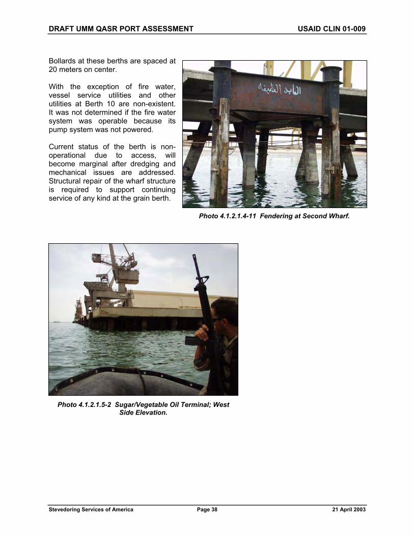
DRAFT UMM QASR PORT ASSESSMENT USAID CLIN 01-009
Stevedoring Services of America Page 38 21 April 2003
Bollards at these berths are spaced at 20 meters on center.
With the exception of fire water, vessel service utilities and other utilities at Berth 10 are non-existent. It was not determined if the fire water system was operable because its pump system was not powered.
Current status of the berth is non-operational due to access, will become marginal after dredging and mechanical issues are addressed. Structural repair of the wharf structure is required to support continuing service of any kind at the grain berth.
Photo 4.1.2.1.4-11 Fendering at Second Wharf.
Photo 4.1.2.1.5-2 Sugar/Vegetable Oil Terminal; West Side Elevation.

DRAFT UMM QASR PORT ASSESSMENT USAID CLIN 01-009
Stevedoring Services of America Page 39 21 April 2003
4.1.2.1.5 Berth 11
Bulk handling of sugar and vegetable oil occurs at Berth 11. It is a T-head pier and has not been evaluated because the facility is not required for the delivery of humanitarian aid products. See Photo 4.1.2.1.5-1.
4.1.2.2 Bulk Berth Recommendations
4.1.2.2.1 Berth 10
Recommended solutions to priority constraints for Berth 10 are as follows.
Structural repairs to the wharf structure.
Structural repairs to the dolphin structures.
Structural repairs to the fender system.
Berth 10 structural repairs to the main wharf section may be accomplished by the addition of reinforcement shotcreted to the damaged bottoms of the caps and to portions of the deck. It is anticipated that approximately 1,433 linear meters of cap and 30 square meters of deck will require repair.
The estimated cost of repair is: US$5,250,000
Berth 10 structural repairs to the dolphins may be accomplished by the addition of reinforcement shotcreted to the entire bottom of each of the cap.
The estimated cost of repair is: US$150,000
Berth 10 structural repairs to the fendering system will require replacement, although, the H piles may be salvaged for reuse in the new fendering system.
The estimated cost of replacement is US$950,000
Other constraints requiring action include the following.
The fire suppression system needs to be brought back on line, refer to Section 8. Berth dredging as described in Section 3 is required.
It is strongly recommended that a thorough underwater inspection of all berths be completed by a licensed engineer/diver with a structural engineering background – and not a typical
Photo 4.1.2.1.5-1 Sugar/Vegetable Oil Terminal; Eastern and Center Portion of the Front Elevation.

DRAFT UMM QASR PORT ASSESSMENT USAID CLIN 01-009
Stevedoring Services of America Page 40 21 April 2003
commercial diver – to verify structural conditions. Neither Coalition Forces nor the SSA group performed an underwater structural inspection. Given the state of maintenance on the rest of the facilities, it is unlikely that one has ever been accomplished.
4.2 BREAKBULK FACILITIES
4.2.1 Operational Condition
4.2.1.1 Breakbulk – Operational – Current Status
The Port of Umm Qasr was designed to handle breakbulk cargo. See Photo 4.2.1.1-1. There are sufficient berths to simultaneously work multiple vessels. Additionally, there are numerous freestanding warehouses for cargo requiring covered protection. Ideally situated, these warehouses are lined up two deep throughout most of the Port with ample paved outside storage areas located between them. These open paved areas are also ideal for traffic flow to and from the vessel as well as providing ample space for the smooth delivery of the cargo to outside trucks. Wide areas also exist between the buildings perpendicular to the berth for ease of traffic flow.
During 2000, the Port of Umm Qasr was reported to be handling over 2 million MT of bagged and general cargo each year, but this assessment is based upon continuing volumes of this magnitude. This is a substantial throughput requiring an infrastructure of reliable crane and support equipment. The Port is clearly organized to accommodate this type of cargo, dedicating a large number of berths with the most obvious constraint for breakbulk operations being the limited amount of equipment available. See Photo 4.2.1.1-2.
The ship to shore portal jib cranes along the berths offer a primary example of the equipment deficiencies. It is estimated that only 20 percent of these cranes can be put into service after a reasonable amount of repair. The rest are either beyond repair or not worth being repaired. Operations would be enhanced if these bad order cranes were simply removed from the terminal. These cranes are further limited in their restricted outreach for larger vessels and SWL capacity.
Photo 4.2.1.1-1 General View of the “New” Port Warehouse Complex.

DRAFT UMM QASR PORT ASSESSMENT USAID CLIN 01-009
Stevedoring Services of America Page 41 21 April 2003
Multiple breakbulk vessel operations will also be severely restricted by the limited availability of operational forklifts. This is especially true for the smaller 3- to 5-ton forklifts, see Photo 4.2.1.1-3. As an example, if three vessels were working simultaneously with multiple gangs, up to thirty-six 3- to 5-ton forklifts would be required. When considering the total forklifts required for vessel, yard, and maintenance operations, the number of smaller lifts quickly multiplies.
Photo 4.2.1.1-3 3-Ton Fork Lift Trucks.
Photo 4.2.1.1-2 General Purpose Portal Cranes in the “New” Port.

DRAFT UMM QASR PORT ASSESSMENT USAID CLIN 01-009
Stevedoring Services of America Page 42 21 April 2003
Apart from forklifts, additional tractors and flatbeds for the movement of various types of breakbulk cargo will also be required. We did identify some trailers that were pulled by traditional type farm tractors. See Photo 4.2.1.1-5. These trailers were approximately 3 meters wide and 5 meters long and are similar to those conventionally used the handling of long steel products in U.S. ports. The condition of the trailers appears to be good but the status of the tractors has not been determined. However, they do appear to be of recent vintage.
Photo 4.2.1.1-5 Flat Trailer for General Cargo Handling.
Photo 4.2.1.1-4 Chinese Manufacture, Dalian Fork Lift Trucks.

DRAFT UMM QASR PORT ASSESSMENT USAID CLIN 01-009
Stevedoring Services of America Page 43 21 April 2003
A search of the Port revealed only a minimum amount of soft gear, i.e., wire rope, slings, nets, shackles, lifting bars, etc. Additional soft gear will be required for vessel operations. Lifting gear of this type should be marked and proof load tested to comply with international regulations affecting safety. The components inspected did not display any form of safe load marking or identification that could be traceable to testing certificates. Nevertheless, most of the gear appeared to be in good condition and could possibly be used in a de-rated application. There is also a requirement for lifting platforms of various types and sizes and a need for large number of cargo boards (pallets) (500 to 1,000 estimated).
Photo 4.2.1.1-7 Freight Container Holding an Assortment of Used and Uncertificated Slings,
Shackles, and Cargo Hooks.
Photo 4.2.1.1-6 Tractor Suitable for Towing Flat, General-Purpose Trailers.

DRAFT UMM QASR PORT ASSESSMENT USAID CLIN 01-009
Stevedoring Services of America Page 44 21 April 2003
4.2.1.2 Other Considerations
Delivery of breakbulk cargo to ultimate destinations will be dependent on the adequacy and availability of rail and truck transportation.
It will be necessary to ascertain from the carrier’s load list the various lot numbers, marks, piece count, and consignee particulars, in order to sort and consolidate shipments for accurate delivery ex-vessel. Such load lists, ship’s stowage plans and cargo manifest, including hazardous and dangerous cargo lists, are required by the Operations Department prior to the vessel’s arrival and are normally provided at the time of sailing from the final loading port.
It should also be noted that in most cases it is not advisable to attempt direct loading to truck or railcar from ship’s hold. Too many variables such as miss tallies, unrecorded cargo damage, and intermittent delays in the movement of trucks or railcars to shipside come into play. A seamless and controlled transition from ship to consignee with full accounting of quantity and destination can best be achieved by moving the goods from shipside to transit warehouse and thence to land transport for delivery to destination.
Methods must be established by the port authorities and Iraq customs control to deal with abandoned cargo. There presently exists cargo on the terminal that was left over prior to the port’s cease of operations that must be identified and distributed.
4.2.1.3 Recommendations
In the near term, we recommend the use of self-contained vessels for the delivery of USAID-funded and humanitarian aid cargo because of the very limited number of working ship to shore terminal cranes.
Photo 4.2.1.1-8 Lifting Beam 35T SWL with Slingsand Lifter Legs.

DRAFT UMM QASR PORT ASSESSMENT USAID CLIN 01-009
Stevedoring Services of America Page 45 21 April 2003
Establish a gear locker to provide, maintain, and control all gear for breakbulk operations. We also recommend the purchase of additional stevedore soft gear listed elsewhere in this report.
Cost Estimate: US$100,000 to US$150,000.
In order to simultaneously work general cargo from three vessels and utilizing four gangs on each vessel, a total of thirty-six 3- to 5-ton forklifts are required.
Cost Estimate: US$35,000 per unit
To work crated and other cargo requires a total of six 15-ton forklifts and four 10-ton forklifts.
Cost Estimate: 10-ton forklift = US$75,000 per unit, 15-ton forklift = US$90,000 per unit
When cargo volumes sufficiently increase and the small shore side cranes now available become too restrictive, consideration should be given to the purchase of a minimum of two mobile harbor cranes. These cranes can efficiently work either breakbulk or containerized cargo. Mobile harbor cranes have the flexibility of easily moving from one berth to another and provide a versatile and reliable shore side support. The purchase of two used or new MPCs with a capacity range of 100 tons is recommended.
Cost Estimate: US$2.5 million per unit
4.2.2 Breakbulk Berth Characteristics
4.2.2.1 Breakbulk Berth Condition Assessment
Three different breakbulk handling facilities occur at Berths 1 to 2, Berths 6 to 8, and Berths 13 to 19. Additionally, breakbulk could also be handled at the container Berths 5 and 20 whose condition is described in section 4.3. All 13 of these berths are equipped with the 4.6-meter gauge crane rails.
4.2.2.1.1 Berths 1 and 2
Berths 1 and 2 are located along a concrete decked and steel pile supported marginal wharf with a vertical sheet pile quay wall along the upland edge. The combined dimension of the wharf at the two berths is approximately 500 meters long by 24.4 meters wide. An upland yard sits in front of two warehouses at Berth 1 and a warehouse building sits along the quay wall at Berth 2.
Photo 4.2.2.1.1-1 Berth 1.

DRAFT UMM QASR PORT ASSESSMENT USAID CLIN 01-009
Stevedoring Services of America Page 46 21 April 2003
The design dredge depth at the face of the berths could not be determined. The dredged depth of the channel adjacent to the berth is shown as -13.2 m CD on Admiralty Chart 1238.
Fendering at Berth 1 consists of two V fenders spaced at 6.1 meters on center bolted to the face of the wharf. The rubber fender elements are in poor shape with UV deterioration and high abrasion evident.
Photo 4.2.2.1.1-2 Berth 2.
Photo 4.2.2.1.1-3 V Fenders at Berth 1 and Buckling Column Fenders at Berth 2.

DRAFT UMM QASR PORT ASSESSMENT USAID CLIN 01-009
Stevedoring Services of America Page 47 21 April 2003
Fendering at Berth 2 consists of buckling column fenders spaced at 12 meters on center and are in poor condition. The facing panel is composed of three steel H piles and a UHMW wearing face.
Bollards along Berth 1 are spaced at 25.9 meters on center and are spaced at 24 meters on center along Berth 2.
The two berths are served by a 4.6-meter gauge crane rails. At Berth 2, two train rail lines run along the wharf. Two additional rail lines perpendicular to the berth extend into the upland yard between the two warehouse buildings at Berth 1. One rail line shown on the site plan is discontinuous before reaching the wharf.
With the exception of fire water, vessel service utilities and other utilities at Berths 1 and 2 are nonexistent. It was not determined if the fire water system was operable because its pump system was not powered.
Lighting at the berths consists of tower mounted HPS light fixtures. Branch circuit wiring on the towers is badly deteriorated and requires replacement. The towers are set up for forty light fixtures each. Currently there are only 8-10 light fixtures per tower.
There is an active cathodic protection system at these berths for the steel pipe piles (see Photo
4.2.2.1.1-5). The status of the system is unknown.
4.2.2.1.2 Berths 6, 7, and 8
Berths 6, 7 and 8 are located along a concrete-decked and steel-pile-supported-marginal wharf with a vertical sheet pile quay wall along the upland edge. The combined dimension of the wharf at the three berths is approximately 630 meters long by 24.7 meters wide. One warehouse at each berth sits along the quay wall.
Photo 4.2.2.1.1-4 Damaged Fender at Berth 1.
Photo 4.2.2.1.1-5 Cathodic Protection Equipment.

DRAFT UMM QASR PORT ASSESSMENT USAID CLIN 01-009
Stevedoring Services of America Page 48 21 April 2003
The design dredge depth at the face of the berths could not be determined. The dredged depth of the channel adjacent to the berth is shown as -13.2-m CD on Admiralty Chart 1238.
Fendering along the berths is light duty and consists of a timber-faced H pile with a square extruded rubber fender to the wharf spaced at just over 3 meters on center. The condition of the fendering system is poor at Berths 6 and 8 and fair at berth 7. About 40 percent of the fenders at berths 6 and 8 were non functional.
Bollards at these berths are spaced at 24.4 meters on center.
The three berths are served by a 4.6-meter gauge crane rails and two rail lines.
Firewater and freshwater services were located along the bullrail at 48.8 meters on center. Other vessel service utilities and other utilities at Berths 6, 7, and 8 are nonexistent. It was not determined if the two water systems were operable because their pump systems were not powered. Lighting at the berths consists of tower mounted HPS light fixtures. Branch circuit wiring on the towers is badly deteriorated and requires replacement. The towers are set up for forty light fixtures each. Currently there are only 8-10 light fixtures per tower
There is an active cathodic protection system at these berths for the steel pipe piles (see Photo 4.2.2.1.1-5). The status of the system is unknown.
Photo 4.2.2.1.2 Berths 6, 7, and 8.
Photo 4.2.2.1.2-2 Damaged Fenders.

DRAFT UMM QASR PORT ASSESSMENT USAID CLIN 01-009
Stevedoring Services of America Page 49 21 April 2003
4.2.2.1.3 Berths 13 through 19
Breakbulk handling facilities at the new port are located from Berth 13 to Berth 19 on the west side of the channel (see Figure 4.1). The 230-meter-long berths consist of a pile-supported marginal wharf ending at a sheet pile retaining wall. The marginal wharf is 25.5 meters wide and supports numerous 2- to 15-ton jib cranes that have a 4.6-meter rail gauge (see Photo 4.2.2.1.3-1). The deck elevation is +6 meter CD.
Construction of the marginal wharf consists of a 1-meter-thick, cast-in-place concrete deck supported by three rows of 1-meter-diameter steel pipe piles. Piles are spaced at 5.5 meters on-center in each direction. The concrete deck thickens to 1.25 meters, 10 meters from the face of the wharf. Additionally, there is a 1.5-meter by 1.5-meter utilidor that runs along the face of the wharf for the entire length of the facility. The
utilidor is supported by two rows of 1-meter-diameter steel pipe piles. The wharf is designed for a load of 4 tons/square meter (800 psf). The design dredge depth at the face of the berths is -12.5-meter CD per Admiralty Chart 1238. A cross-section of the facility can be seen in Photo 4.2.2.1.3-2.
Photo 4.2.2.1.3-2 End of Berth 13. Typical Construction of “New” Port Wharf.
Photo 4.2.2.1.3-1 Berths 13 to 19 with General Cargo Cranes.

DRAFT UMM QASR PORT ASSESSMENT USAID CLIN 01-009
Stevedoring Services of America Page 50 21 April 2003
The fender system consists of tubular rubber elements wrapped around galvanized chains that are slung in a diagonal manner along the face of the berth (see Photo 4.2.2.1.3-3). Fender elements are spaced at 8 meters along the wharf.
Bollards at these berths are spaced at 45 meters.
Utilities at the facility include a fire suppression line and water line that are run
in the utilidor. Access points for these are located in deck hatches at 90-meter intervals. At this time the water is not potable and neither system is charged.
The high-voltage (11kv) switchgear is damaged. The transformers are low on oil and some are leaking. The low voltage (400v) switchgear is damaged and some fuses have been changed to straight copper wire.
The structure is less than 20 years old and appears to be in excellent condition. No serious deterioration of the concrete was observed nor was there any corrosion of the steel piling noted (see Photo 4.2.2.1.3-4). There has been some cosmetic damage to the face of the structure.
The utilidor at the wharf face contains crane connections and ship power connections. Most have been disconnected or have had the cables cut. See Photo 4.2.2.1.3-5.
Lighting towers have individual branch circuit breakers for each tower. On the secondary side of the breaker, branch wiring is spliced to run to 40 individual ballasts mounted at the bottom of the tower structure. The branch circuit wiring is routed up the light tower structure for 40 light fixtures, but most towers have only 8 to 20 light fixtures. All lights on the tower are all on or all off. There is no switching capability to have Photo 4.2.2.1.3-4 Typical Pile Condition
at “New” Port.
Photo 4.2.2.1.3-3 “New” Port Fender System.
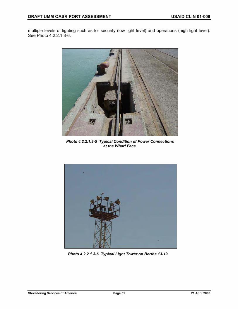
DRAFT UMM QASR PORT ASSESSMENT USAID CLIN 01-009
Stevedoring Services of America Page 51 21 April 2003
multiple levels of lighting such as for security (low light level) and operations (high light level). See Photo 4.2.2.1.3-6.
Photo 4.2.2.1.3-5 Typical Condition of Power Connections at the Wharf Face.
Photo 4.2.2.1.3-6 Typical Light Tower on Berths 13-19.

DRAFT UMM QASR PORT ASSESSMENT USAID CLIN 01-009
Stevedoring Services of America Page 52 21 April 2003
4.2.2.2 Breakbulk Berth Recommendations
4.2.2.2.1 Recommendations – Berths1, 2, 6, 7, and 8
Recommended solutions to priority constraints for Berths 1, 2, 6, 7, and 8 are as follows.
Structural repairs to fendering system.
Berth 1 structural repairs to the fendering system will require replacement. Berth 2 structural repairs to the fendering system will require replacement of half the rubber elements and refurbishment to half the frames.
Estimated cost of repair and replacement at Berths 1 and 2: US$900,000.
Berths 6, 7, and 8 structural repairs to the fendering system will require replacement.
Estimated cost of replacement at Berths 6, 7, and 8: US$1,250,000.
Do not operate wharf equipment until the 11KV infrastructure, transformers, and low voltage (400v) switchgear are replaced.
Provide a separate power feed for the light towers on Berths 13-19. Provide hand-off-auto switching with photocell control. Provide 2 separate power feeds at each light tower to allow for security level lighting and operations level lighting. Provide additional circuit breaker at each light tower to allow for separation of security lighting from operational lighting. Clean, re-lamp, and test all light fixtures/ballasts. Provide additional light fixtures as necessary. Estimated cost US$250,000.
Other constraints requiring action include:
The fire suppression system needs to be brought back on line, refer to Section 8.
Berth dredging is required. See Section 3.
It is strongly recommended that a thorough underwater inspection of all berths be completed by a licensed engineer/diver with a structural engineering background – and not a typical commercial diver – to verify structural conditions. Neither coalition forces nor the SSA group performed an underwater structural inspection. Given the state of maintenance on the rest of the facilities, it is unlikely that one has ever been accomplished.
4.2.2.2.2 Recommendations – Berths 13 through 19
Recommendations for repair of Berths 13 through 19 are as follows.
Berth dredging is required. See Section 3.
Do not operate wharf equipment until the 11KV infrastructure, transformers, and low voltage (400v) switchgear are replaced.

DRAFT UMM QASR PORT ASSESSMENT USAID CLIN 01-009
Stevedoring Services of America Page 53 21 April 2003
Provide three separate power feeds for the light towers. At each of these locations provide hands-off auto-switching with photocell control. Provide separate power feeds to the light towers to allow for security level lighting and operations level lighting. Provide additional circuit breaker at light tower to allow for separation of security lighting from operational lighting. Clean, re-lamp, and test all light fixtures/ballasts. Provide additional light fixtures as necessary. Estimated Cost: US$250,000.
It is strongly recommended that a thorough underwater inspection of all berths be completed by a licensed engineer/diver with a structural engineering background – and not a typical commercial diver – to verify structural conditions. Neither coalition forces nor the SSA group performed an underwater structural inspection. Given the state of maintenance on the rest of the facilities, it is unlikely that one has ever been accomplished.
The fire suppression system needs to be brought back on line.
The potable water system needs to be sanitized and brought back on line.
These repair items will be accomplished under a broader water system refurbishment, refer to Section 8 for further details.
4.3 CONTAINER FACILITIES
4.3.1 Operational Condition
4.3.1.1 Container Operational – Current Status
Waterside handling facilities is comprised of two quayside cranes in the “new” port manufactured by Chinese Company ZPMC during 2001 and understood to have been commissioned in Umm Qasr during 2002.
Two Nelcon quay cranes are installed in the “old” port serving Berth 5, see Photo 4.3.1.1-1. These Nelcon cranes are very old and the condition is unknown. One crane suffered damage to its cable reel assembly as the conflict started and it has been stuck in a boomed down position. See Photo 4.3.1.1-2.
Photo 4.3.1.1-1 Nelcon Quay Crane, “Old” Port, Berth 5.

DRAFT UMM QASR PORT ASSESSMENT USAID CLIN 01-009
Stevedoring Services of America Page 54 21 April 2003
In view of the relatively low volume of container cargo anticipated in the short term (28,185 Twenty-Foot Equivalent Units [TEU] during year 2000) and in order to consolidate most of the priority USAID cargo handling activities within the “new” port, this report focuses upon the utilization of the ZPMC cranes that appear to be in relatively good, although untested condition. See Photo 4.3.1.1-3. The cranes were inspected as far as possible during the assessment period when electrical power was available to operate the drives, but it was noted that the specification was quite basic, having Chinese drive and brake components along with operational speeds only half that which would normally be expected on cranes of this vintage and type. The inspections revealed that some important electrical safety components had been disconnected from circuit. No maintenance history could be located, details of certification are unknown, and critical items such as wire ropes and twist locks are without proof load test certificates.
The boom-locking latches on both cranes are not engaged having been electrically disconnected, leaving the cranes in a compromised safety condition.
Although spare parts stores were located at both “new” and “old” port areas, there was no evidence of suitable spares to support the cranes even though procurement of many of the components, such as gear boxes and motors, are known to have long lead times, as much as 6 months in some cases. Cranes of this type often sustain damage to the lifting frame (spreader) during operation and it is normal to have a spare
Photo 4.3.1.1-2 Damage to One of the Nelcon Cranes.
Photo 4.3.1.1-3 Two ZPMC Container Cranes at Berth 20.

DRAFT UMM QASR PORT ASSESSMENT USAID CLIN 01-009
Stevedoring Services of America Page 55 21 April 2003
available that can be quickly fitted in order to avoid unnecessary vessel delay - no spare spreader is available at either location and the Nelcon/ZPMC spreaders are not interchangeable.
Landside handling facilities are adequately served by approximately 7-plus hectares of paved terminal storage area, conveniently located immediately behind the quayside crane berths. There is an additional 10 to 15 hectares of additional paved storage capacity in close proximity, immediately to the north of the container berth.
An adequate gate setup for all container movement at current volume levels exists on the western perimeter of the “new” port. It is well located for easy access to the container yard area and has a good queuing space. There are also scales for both inbound and outbound activity, although they are not currently in working order. Further examination would be required for an accurate cost estimate to put them in working order. There are also two overhead inspection stations at the out-gate lanes. There is also space and ability to open another gate located in the northeast corner of the “new” port as truck traffic and cargo volumes warrant.
It should also be pointed out that rail access for the entire “new” port area enters and exits near the northwest perimeter of the “new” port, directly north of the main port administration building. There is ample trackage through the container area to facilitate loading of flatbed rail cars with top pick lift trucks. The one negative to the trackage layout is the fact all rail movement south of the container berth (i.e., Berths 13 through 19) must traverse the container yard. The impact to the operation of the container yard should be lessened through good coordination and cooperation with the port and the rail. Two working shunting locomotives with Mercedes engines are available and in working order within the port itself, which will greatly enhance and minimize cargo operation interruptions in the container area.
The approach to be adopted for storage and transport of containers to and from the quayside cranes will depend upon the availability of existing heavy lift and transport equipment. In reviewing the type of equipment available, it would appear that the port was not particularly well organized according to conventional standards for container handling. SSA would expect to see either (1) a straddle carrier operation whereby containers are transported between quayside cranes and stacking isles by the carriers or (2) a tractor/chassis operation with the stacking handled by yard cranes or top picks. There are four new Belotti straddle carriers (See Photo 4.3.1.1-4) located in the “old” port but, at the time of our inspection the carriers were not operating and it has been confirmed they were never commissioned. An earlier report generated by the Transport and Food Handling Sector Working Group in June 2002 indicated the straddle carriers were not assembled or commissioned Photo 4.3.1.1-4 Four Belotti Straddle Carriers.

DRAFT UMM QASR PORT ASSESSMENT USAID CLIN 01-009
Stevedoring Services of America Page 56 21 April 2003
despite having been delivered one year earlier. We are aware that Belotti is no longer manufacturing this type of equipment, which was only ever produced in low numbers but that the company CVS Ferrari may have taken over support activities. In full reliable operating condition, these straddle carriers should be quite capable of transporting and stacking ISO freight containers within the configuration and volumes anticipated but since they have never been used, it is considered reasonable to plan for a second option. It should be noted however, that this type of equipment has a history of extremely high maintenance costs.
This second option could utilize four CVS Ferrari top picks (see Photo 4.3.1.1-5) that are available in the “new” port but would also need to be supplemented by yard tractors and specialized container chassis to transport containers to and from the stacking area. Only three of the CVS top picks are operational, the fourth was damaged and partially overturned while attached to a heavy 20-foot ISO container. At the time of inspection, the spreader had been disconnected from the machine but remained locked onto the damaged container (see Photo 4.3.1.1-6). The spreader itself appears to have suffered minimal, if any damage, and should be easily returned to operational condition.
Two of the four top picks may be operated as 42-ton fork lift trucks; two have permanently mounted spreaders for container handling operation only.
In addition, it was noted that the chassis of three new CVS Ferrari top pick chassis were still loaded onto rail cars within the “old” port (see Photo 4.3.1.1-7). They are missing key components such as mast, axles, and spreaders. The missing components could be containerized elsewhere in the port. The supplier has been contacted and we await his input to determine if and when this equipment could be considered for future operation in Umm Qasr.
Photo 4.3.1.1-5 CVS Ferrari Top Pick.
Photo 4.3.1.1-6 One Spreader of a CVS Ferrari Top Pick Remains Locked onto a Damaged 20-Foot ISO Container.
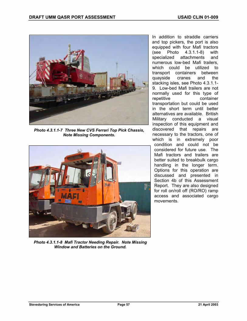
DRAFT UMM QASR PORT ASSESSMENT USAID CLIN 01-009
Stevedoring Services of America Page 57 21 April 2003
In addition to straddle carriers and top pickers, the port is also equipped with four Mafi tractors (see Photo 4.3.1.1-8) with specialized attachments and numerous low-bed Mafi trailers, which could be utilized to transport containers between quayside cranes and the stacking isles, see Photo 4.3.1.1-9. Low-bed Mafi trailers are not normally used for this type of repetitive container transportation but could be used in the short term until better alternatives are available. British Military conducted a visual inspection of this equipment and discovered that repairs are necessary to the tractors, one of which is in extremely poor condition and could not be considered for future use. The Mafi tractors and trailers are better suited to breakbulk cargo handling in the longer term. Options for this operation are discussed and presented in Section 4b of this Assessment Report. They are also designed for roll on/roll off (RO/RO) ramp access and associated cargo movements.
Photo 4.3.1.1-7 Three New CVS Ferrari Top Pick Chassis, Note Missing Components.
Photo 4.3.1.1-8 Mafi Tractor Needing Repair. Note Missing Window and Batteries on the Ground.

DRAFT UMM QASR PORT ASSESSMENT USAID CLIN 01-009
Stevedoring Services of America Page 58 21 April 2003
4.3.1.2 Container Operational – Other Considerations
A manual system could be used to control the vessel operations, inventory, and gate operations in the short term. However, a stand-alone PC-based computer system should be considered preferable within a 6-to 18-month time frame to efficiently control container operations. Eventually, the manual control of container movement will become too burdensome.
Some striping for yard layout will be necessary to facilitate vessel and gate activity. Numbering of the layout eases location identification and speeds up operational control.
Procedures will need to be established at the direction of USAID so that cargo shipments can be identified for discharge and delivered out the gate to their respective consignees by bill of lading or container number.
Consideration must be given to the need for Customs vessel entry and clearance inward procedures, together with a cargo manifest, inspection, regulation, and cargo clearance rules. Such rules and practices normally emanate from the Ministries of Finance and Commerce. A simplified, streamlined system for humanitarian aid cargo must be established.
Intermodal variables outside of the terminal’s control must be addressed. Sufficient trucking and rail resources will be required for the efficient movement of all cargoes to inland destinations.
The SSA port assessment team strongly believes there is a very good opportunity for optimum use of containerization of breakbulk cargoes, given the high percentage of bagged, unitized, and drum cargo to be handled.
The economies of scale are readily apparent when the dwell time of a vessel is considered. As an example, to discharge a conventional vessel loaded with 14,000 tons of bagged rice will
Photo 4.3.1.1-9 Typical Mafi Trailer. Note Specialized Attachment Fitting.

DRAFT UMM QASR PORT ASSESSMENT USAID CLIN 01-009
Stevedoring Services of America Page 59 21 April 2003
require 14 to 16 days, whereas a feeder vessel (of similar charter hire costs) carrying 700 containers laden with the same tonnage of rice can be discharged within 2 days.
The improved logistics of distribution and control are also considerable. Losses due to damage and pilferage are drastically reduced. The facilities available are more than adequate to support an efficient container terminal operation in excess of 100,000 TEUs per year.
There is no evidence of refrigerated container plug-in points located anywhere throughout the port. This can be easily remedied by use of a portable container generator, specifically designed for this purpose. These are readily available and come in various sizes ranging from 20 to 40 plugs. Individual gensets are available to run and support single refrigerated containers for isolated or special circumstances.
4.3.1.3 Container Operational – Recommendations
We would propose the following measures to provide a reliable container handling operation that could conservatively support a container throughput up to 100,000 TEU per annum; i.e., far in excess of the humanitarian and reconstructive needs of USAID.
There is adequate crane capacity and space within the “new” port to accomplish anticipated container volumes for the foreseeable future. Navigational and berthing requirements are currently not adequate for Panamax size vessels, but it is understood that separate contracts to achieve such realities will very quickly be placed. These recommendations, therefore, concentrate short-term operations within the “new” port complex, using existing equipment wherever possible to provide the quickest possible service, but planning for a more reliable, efficient, and expanded operation as and when additional facilities become available.
Seaside Handling - Two ZPMC Quay Cranes
It is recommended to identify these cranes as the principle seaside handling equipment, having substantial capacity to work vessels quickly and efficiently. Although two cranes may theoretically provide excess capacity for short-term needs, it is necessary to provide redundancy and speed of operation to minimize delays and reduce vessel turn-around times. Additionally, these cranes can be utilized to handle break and heavy lift cargo. There are two specialized cargo hook attachments with a safe working load of 45 tons each.
a. Procure services of specialist electrical/electronic engineer for purpose of checking main drives, function testing the operation, creating records of test, certifying the mechanisms, and training of maintenance personnel. It is noted that a test weight configured in the form of a converted 40-foot ISO freight container is located behind the Quay cranes and it is assumed that this will be suitable for proof load testing the cranes.
Cost Estimate: US$80,000
b. Procure two each of 1MVA electrical generator, one for each crane to support the container handling operation until dependable power from the grid has been restored. These generators will require addition of special pump-back resistors, controllers, and resistor bank to absorb regenerative power during the crane lowering cycle. ZPMC assistance is necessary for this design.
Cost Estimate: US$800,000 Outright purchase for two generators.

DRAFT UMM QASR PORT ASSESSMENT USAID CLIN 01-009
Stevedoring Services of America Page 60 21 April 2003
This would enable the cranes to be operational prior to the restored shore side power being reinstated. This shore power has been estimated to be 6 to 8 months away.
c. Procure one spare telescopic spreader.
Cost Estimate: US$125,000
This could possibly be a used unit at a slightly reduced price.
d. Procure one set of consumable spare parts inclusive of wire ropes, gearboxes, motors, brakes, trolley wheels, cables, switches, drive components, etc.
Cost Estimate: US$750,000
e. Procure three sets of Engineering Documentation - Maintenance, Spare Parts, Operator and Workshop Manuals inclusive of electrical circuit diagrams, hydraulic and mechanical drawings.
Cost Estimate: US$40,000
Landside Handling – Option 1 Four Belotti Straddle Carriers
Establish source for ongoing support of this equipment. Proceed with investment only if support can be guaranteed.
Note: Since completing our site inspections, the company CVS Ferrari has confirmed its takeover of the Belotti interests. They informed SSA that the commissioning of the four Straddle carriers was never completed due to a problem with funding. From an operational perspective, there is a concern that the machines have been standing idle for two years without attention and there are likely to be problems, which could potentially interrupt the operation for long periods. Given the uncertainty about the equipment design, its relative complexity and unproven track record, we strongly recommend Option 2 (top picks) be adopted as the preferred approach to be taken in the short term. In the meantime, it would be sensible to complete the commissioning and continue reliability testing of the strads until a satisfactory performance level can be achieved. In the event future container throughput increases beyond the capacity of the top picks, then it would be possible to bring the straddle carriers on line as additional or enhanced landside support.
a. Procure services of manufacturer’s engineer for purpose of re-commissioning the straddle carriers, performing function tests, maintenance, and operator training.
Cost Estimate: US$80,000 (awaiting CVS Ferrari input)
b. Procure one set of consumable spare parts inclusive of wire ropes, filters, engine, gearboxes, transmission components, cylinders, switches, controllers, brake parts, pumps, bearings wheels, and tires.
Cost Estimate: US$300,000

DRAFT UMM QASR PORT ASSESSMENT USAID CLIN 01-009
Stevedoring Services of America Page 61 21 April 2003
c. Procure three sets engineering documentation - Maintenance, Spare Parts, Operator, and Workshop Manuals inclusive of electrical circuit diagrams, hydraulic, and mechanical drawings.
Cost Estimate: US$20,000
Landside Handling – Option 2 Four CVS Top Picks
These top picks are reliable, simple to maintain, and have a proven track record in container handling operations. Although one of the three is damaged, SSA believes it can quickly be repaired at a low cost.
a. Procure one set of consumable spare parts to support top picks, yard tractors, and chassis.
Cost Estimate: US$150,000
b. Container movement to and from stacking areas in the short term could be accomplished using existing Mafi tractors and trailers until the container volumes begin to ramp up. British Military conducted a visual inspection of the equipment and discovered that repairs are necessary to the tractors to function correctly. One of the four tractors is in a poor condition and could not be considered for future use. The existing Mafi tractors and trailers are better suited to breakbulk cargo handling and RO/RO operations. Options for this operation are discussed and presented in Section 4b and 4d of this Assessment Report.
Procure 10 tractors with elevating fifth wheel. Cost Estimate: US$1,000,000
Procure 10 container chassis trailers. Cost Estimate: US$200,000
4.3.2 Container Berth Characteristics
4.3.2.1 Container Berth Condition Assessment
Container berths occur in the “old” port at Berth 5 and in the “new” port at Berth 20.
4.3.2.1.1 Berth 5
Berth 5 is located along a concrete-decked and steel-pile-supported marginal wharf with a vertical sheet pile quay wall along the upland edge. See Photo 4.3.2.1.1-1 and Photo 4.3.2.1-2. The wharf dimensions are 250 meters long by 37.5 meters wide. An upland yard
Photo 4.3.2.1.1-1 Berth 5 Looking North.
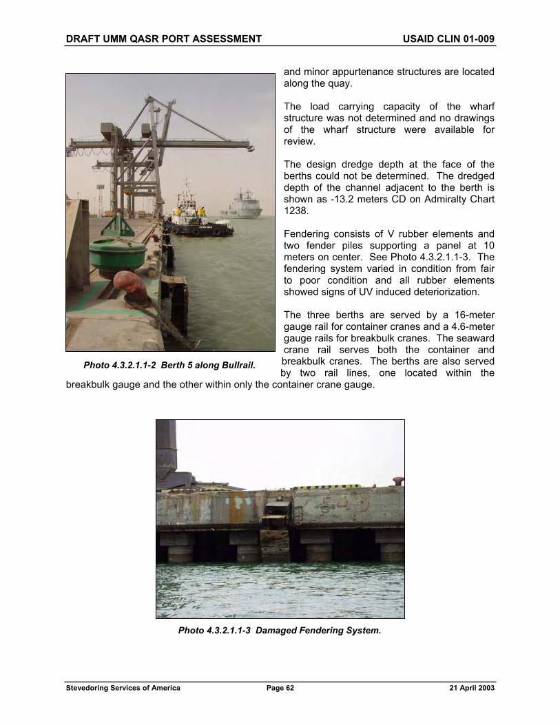
DRAFT UMM QASR PORT ASSESSMENT USAID CLIN 01-009
Stevedoring Services of America Page 62 21 April 2003
and minor appurtenance structures are located along the quay.
The load carrying capacity of the wharf structure was not determined and no drawings of the wharf structure were available for review.
The design dredge depth at the face of the berths could not be determined. The dredged depth of the channel adjacent to the berth is shown as -13.2 meters CD on Admiralty Chart 1238.
Fendering consists of V rubber elements and two fender piles supporting a panel at 10 meters on center. See Photo 4.3.2.1.1-3. The fendering system varied in condition from fair to poor condition and all rubber elements showed signs of UV induced deteriorization.
The three berths are served by a 16-meter gauge rail for container cranes and a 4.6-meter gauge rails for breakbulk cranes. The seaward crane rail serves both the container and breakbulk cranes. The berths are also served by two rail lines, one located within the
breakbulk gauge and the other within only the container crane gauge.
Photo 4.3.2.1.1-2 Berth 5 along Bullrail.
Photo 4.3.2.1.1-3 Damaged Fendering System.

DRAFT UMM QASR PORT ASSESSMENT USAID CLIN 01-009
Stevedoring Services of America Page 63 21 April 2003
With the exception of fire water, vessel service utilities and other utilities at Berth 5 are nonexistent. It was not determined if the fire water system was operable because its pump system was not powered. Lighting at the berth consists of tower mounted HPS light fixtures. The branch circuit wiring is badly deteriorated and requires replacement. Each tower is set up to have 40 light fixtures. Currently there are 8-10 light fixtures on each tower. See Photo 4.3.2.1.1-4.
There is an active cathodic protection system at these berths for the steel pipe piles (see Photo 4.2.2.1.1-5). The status of the system is unknown.
4.3.2.1.2 Berth 20
Container-handling facilities at the “new” port are located at Berth 20 towards the northwest corner of the port (see Figure 4.1). The 535-meter-long berth consists of a pile-supported marginal wharf ending at a sheet pile retaining wall. The marginal wharf is 25.5 meters wide and supports two 40-ton container cranes that have a 30-meter rail gauge. The deck elevation is +6 meters CD. Berth 20 can be seen in Photo 4.3.2.1.2-1.
Construction of the marginal wharf consists of a 1-meter-thick, cast-in-place concrete deck supported by three rows of 1-meter-diameter steel pipe piles. Piles are spaced at 5.5 meters on-center in each direction. The concrete deck thickens to 1.25 meters, 10 meters from the face of the wharf. Additionally, there is a 1.5-meter by 1.5-meter utilidor that runs along the face of the wharf for the entire length of the facility. The utilidor is supported by two rows of 1-meter-diameter steel pipe piles. The design dredge depth at the face of the berth is
Photo 4.3.2.1.2-1 Container Cargo Facility at Berth 20.
Photo 4.3.2.1.1-4 Typical Light Tower at Berth 5.

DRAFT UMM QASR PORT ASSESSMENT USAID CLIN 01-009
Stevedoring Services of America Page 64 21 April 2003
-12.5 meter CD per Admiralty Chart 1238. A cross-section of the facility can be seen in Photo 4.2.2.1.3-2.
The fender system consists of tubular rubber elements wrapped around galvanized chains that are slung in a diagonal manner along the face of the berth (see Photo 4.2.2.1.3-3). Fender elements are spaced at 8 meters along the wharf.
Bollards at the berth are spaced at 45 meters.
Utilities at the facility include a fire suppression line and water line that are run in the utilidor. Access points for these are located in deck hatches at 90-meter intervals. At this time the water is not potable and neither system is charged.
The high voltage (11kv) switchgear is damaged. The transformers are low on oil and some are leaking. The low voltage (400v) switchgear is damaged and some fuses have been changed to straight copper wire.
No disconnects were found for the 40-ton ZPMC container cranes. The connection appears to have been accomplished with a straight splice into the 11KV ring system at the wharf utilidor. See Photo 4.3.2.1.2-2.
The utilidor at the wharf face contains crane connections and ship power connections. Most have been disconnected or have had the cables cut.
Lighting towers have individual branch circuit breakers for each tower. On the secondary side of the breaker, branch wiring is spliced to run to 40 individual ballasts mounted at the bottom of the tower structure. The branch circuit wiring is routed up the light tower structure for 40 light fixtures, but most towers have only 8 to 10 light fixtures.
All lights on the tower are all on or all off. There is no switching capability to have multiple levels
of lighting such as for security (low light level) and operations (high light level).
The structure is less than 20 years old and appears to be in excellent condition. No serious deterioration of the concrete was observed nor was there any corrosion of the steel piling noted (see Photo 4.2.2.1.3-4). There has been some cosmetic damage to the face of the structure.
Photo 4.3.2.1.2-2 Typical Straight Splice into 11kV System at Wharf Face.
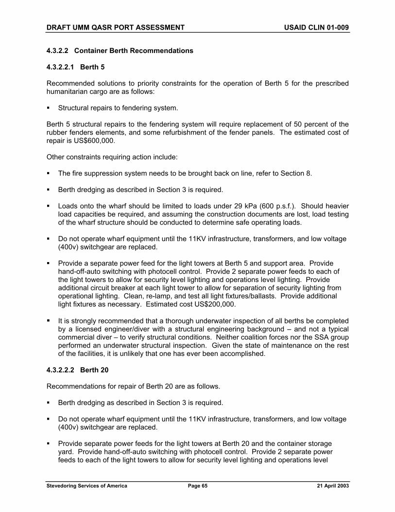
DRAFT UMM QASR PORT ASSESSMENT USAID CLIN 01-009
Stevedoring Services of America Page 65 21 April 2003
4.3.2.2 Container Berth Recommendations
4.3.2.2.1 Berth 5
Recommended solutions to priority constraints for the operation of Berth 5 for the prescribed humanitarian cargo are as follows:
Structural repairs to fendering system.
Berth 5 structural repairs to the fendering system will require replacement of 50 percent of the rubber fenders elements, and some refurbishment of the fender panels. The estimated cost of repair is US$600,000.
Other constraints requiring action include:
The fire suppression system needs to be brought back on line, refer to Section 8.
Berth dredging as described in Section 3 is required.
Loads onto the wharf should be limited to loads under 29 kPa (600 p.s.f.). Should heavier load capacities be required, and assuming the construction documents are lost, load testing of the wharf structure should be conducted to determine safe operating loads.
Do not operate wharf equipment until the 11KV infrastructure, transformers, and low voltage (400v) switchgear are replaced.
Provide a separate power feed for the light towers at Berth 5 and support area. Provide hand-off-auto switching with photocell control. Provide 2 separate power feeds to each of the light towers to allow for security level lighting and operations level lighting. Provide additional circuit breaker at each light tower to allow for separation of security lighting from operational lighting. Clean, re-lamp, and test all light fixtures/ballasts. Provide additional light fixtures as necessary. Estimated cost US$200,000.
It is strongly recommended that a thorough underwater inspection of all berths be completed by a licensed engineer/diver with a structural engineering background – and not a typical commercial diver – to verify structural conditions. Neither coalition forces nor the SSA group performed an underwater structural inspection. Given the state of maintenance on the rest of the facilities, it is unlikely that one has ever been accomplished.
4.3.2.2.2 Berth 20
Recommendations for repair of Berth 20 are as follows.
Berth dredging as described in Section 3 is required.
Do not operate wharf equipment until the 11KV infrastructure, transformers, and low voltage (400v) switchgear are replaced.
Provide separate power feeds for the light towers at Berth 20 and the container storage yard. Provide hand-off-auto switching with photocell control. Provide 2 separate power feeds to each of the light towers to allow for security level lighting and operations level

DRAFT UMM QASR PORT ASSESSMENT USAID CLIN 01-009
Stevedoring Services of America Page 66 21 April 2003
lighting. Provide additional circuit breaker at each light tower to allow for separation of security lighting from operational lighting. Clean, re-lamp, and test all light fixtures/ballasts. Provide additional light fixtures as necessary. Estimated cost US$300,000.
It is strongly recommended that a thorough underwater inspection of all berths be completed by a licensed engineer/diver with a structural engineering background – and not a typical commercial diver – to verify structural conditions. Neither coalition forces nor the SSA group performed an underwater structural inspection. Given the state of maintenance on the rest of the facilities, it is unlikely that one has ever been accomplished.
The fire suppression system needs to be brought back on line, refer to Section 8.
The potable water system needs to be sanitized and brought back on line, refer to Section 8.
These repair items will be accomplished under a broader water system refurbishment, refer to Section 8 for further details.
4.4 RO/RO
4.4.1 Operational Condition
4.4.1.1 RO/RO Operational – Current Status
The Port has a virtually new and well laid out RO/RO ramp located at Berth 21, which adjoins the container terminal at the north end.
This ramp is well designed and able to support traffic moving to and from a RO/RO vessel. It is 40 meters long and 18 meters wide on the land side end. Minimal repairs will be required to the steel deck plating closest to the water edge of the ramp.
Photo 4.4.1.1-1 RO/RO Ramp Berth 21.
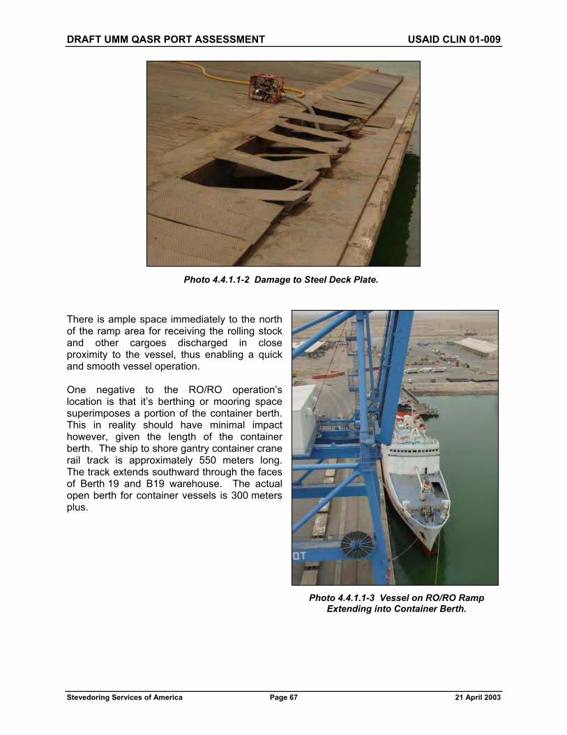
DRAFT UMM QASR PORT ASSESSMENT USAID CLIN 01-009
Stevedoring Services of America Page 67 21 April 2003
There is ample space immediately to the north of the ramp area for receiving the rolling stock and other cargoes discharged in close proximity to the vessel, thus enabling a quick and smooth vessel operation.
One negative to the RO/RO operation’s location is that it’s berthing or mooring space superimposes a portion of the container berth. This in reality should have minimal impact however, given the length of the container berth. The ship to shore gantry container crane rail track is approximately 550 meters long. The track extends southward through the faces of Berth 19 and B19 warehouse. The actual open berth for container vessels is 300 meters plus.
Photo 4.4.1.1-2 Damage to Steel Deck Plate.
Photo 4.4.1.1-3 Vessel on RO/RO Ramp Extending into Container Berth.

DRAFT UMM QASR PORT ASSESSMENT USAID CLIN 01-009
Stevedoring Services of America Page 68 21 April 2003
The specialized Mafi trucks will be utilized to remove crated machinery, long steel, and unit lots of general cargo from the holds of RO/RO vessels.
Photo 4.4.1.1-4 Container Crane Track Extends to South End of Berth 19 Shed.
Photo 4.4.1.1-5 Mafi Trailer Used for Transporting RO/RO Cargo.

DRAFT UMM QASR PORT ASSESSMENT USAID CLIN 01-009
Stevedoring Services of America Page 69 21 April 2003
Minimal soft gear is required such as tools for unlashing cargo, stevedore boards, and bolsters for ease of landside movement etc. Low mast forklifts capable of operating within the ship are a critical component on many RO/RO vessels. Most often, the ship itself will carry this type of equipment on board. This must be clarified because the current forklift inventory does not include this type of equipment.
4.4.2 RO/RO Berth Characteristics
4.4.2.1 RO/RO Berth Condition Assessment
The RO/RO facility is located at Berth 21 in the northwest corner of the “new” port (see Figure 4.1). It consists of a 55-meter-long steel ramp hinged at the shoreward end and supported by eighteen 2.5-meter by 5.5-meter floating pontoons on the seaward end. The ramp access is 8 meters wide on shore and tapers out to a width of 27 meters on the leading edge. The RO/RO ramp can be seen in Photo 4.4.2.1.1-1.
For access to the RO/RO ramp, ships are moored alongside at Berth 20; therefore, the fender system and utilities are those detailed in the Container Cargo section. There is a timber rub strip on the leading edge of the RO/RO ramp itself. The design dredge depth at the face of the ramp is -12.5-meter CD per Admiralty Chart 1238.
The RO/RO facility appears to be in very good condition. The rocker hinges at the head of the ramp are in excellent working order as are the guide beams on either side of the seaward end. There is no discernible deterioration of the ramp beams or deck. The pontoons also looked to be in very good condition.
4.4.2.2 RO/RO Berth Recommendations
There are no repairs recommended at this facility.
4.5 PROJECT CARGO/HEAVY LIFT – CURRENT STATUS
The new ZPMC cranes are equipped with specialized cargo lifting beams (one each) with a safe working load (SWL) rating of 45 tons. These beams attach directly to the container crane using a twistlock interface and replace the conventional container handling spreader.
Photo 4.4.1.1-6 Mafi Tractor, Which has a Special Gooseneck Attachment for Towing Mafi Trailer.

DRAFT UMM QASR PORT ASSESSMENT USAID CLIN 01-009
Stevedoring Services of America Page 70 21 April 2003
The beams have a center swivel, rams horn hook attachment in addition to four 12 Ton SWL padeyes, two at each end. Depending on the dimensions and type of cargo to be removed from the vessel, additional spreader bars may be required to provide a safe hoist in a way which will protect and prevent collapse of the load. Sets of slings of various lengths, various diameters, are also required to facilitate the removal of the cargo depending on the weight and size of the cargo load involved.
The old port Nelcon container cranes have only one total heavy lift beam. The safe working load of this hook is unknown.
A big plus with the ZPMC cranes is the ability to travel the cranes the entire length of berth 19 to work a conventional vessel needing heavy lift / project cargo hoisting capability.
Photo 4.5-1 45-Ton Heavy Lift Cargo Beam for ZPMC Container Cranes.
Photo 4.5-2 47-Ton Heavy Lift Cargo Beam for Nelcon Container Cranes.

DRAFT UMM QASR PORT ASSESSMENT USAID CLIN 01-009
Stevedoring Services of America Page 71 21 April 2003
4.6 OTHER OPERATIONAL FACTORS
The gear locker support will need vehicles to support the operation and distribute needed soft gear to all ships gangs and dockmen throughout the working area. The requirement would be for one 3/4-ton flatbed truck and two half-ton pickups.
Cost Estimate: US$55,000
Cargo plates, low-mast 3-ton forklifts, blocking/bracing supplies, and banding equipment will be utilized for transloading, recoopering, or building loads for onward movement.
Cost Estimate: US$60,000
Portable generator powered light standards with telescopic mast towers will be required for night operations. Until power is restored from the grid, operational hours will be severely hampered or impossible without such support. Eight portable light standards will, therefore, be required.
Cost Estimate: US$40,000
Hazardous material handling equipment will be needed to support the handling or recoopering of hazardous cargo. Please refer to Section 10 for more details.
Cost Estimate: US$85,000
A dedicated training program will need to be developed for crane operators, winch drivers, heavy equipment operators, mechanics, and supervisory and maintenance personnel. The extent of this program cannot be fully determined until SSA ascertains the skill level and the availability of the former Port employees. At that time, it can be determined if they have sufficient skill levels to, in turn, train new employees or whether it will be required to bring in out-of-country trainers.
The Port will require a medical clinic/first aid station for all employees. Suitable transportation to move an injured person either within the Port or off the Port to a local medical facility is also required.
Cost Estimate: US$100,000
Additional buses will be required to augment what is currently at the Port. Given the number of employees anticipated, four additional buses for timely movement to the jobsite from the nearby town will be required.
Cost Estimate: US$280,000
Vehicles will be required for operations personnel, both vessel and yard. Six pickup trucks will be required for each department for superintendents and supervisory personnel.
Cost Estimate: US$240,000

DRAFT UMM QASR PORT ASSESSMENT USAID CLIN 01-009
Stevedoring Services of America Page 72 21 April 2003
A cafeteria will be required at the Port to serve meals to Port employees, including stevedore labor. Given the distance from their homes, a mid-shift meal will need to be provided. Confirmation of past practice in the Port area regarding meals is being ascertained.
Cost Estimate: US$400,000
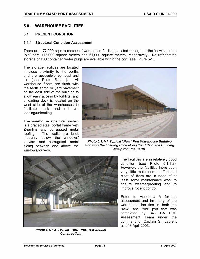
DRAFT UMM QASR PORT ASSESSMENT USAID CLIN 01-009
Stevedoring Services of America Page 73 21 April 2003
5.0 — WAREHOUSE FACILITIES
5.1 PRESENT CONDITION
5.1.1 Structural Condition Assessment
There are 177,000 square meters of warehouse facilities located throughout the “new” and the “old” port; 116,000 square meters and 61,000 square meters, respectively. No refrigerated storage or ISO container reefer plugs are available within the port (see Figure 5-1).
The storage facilities are located in close proximity to the berths and are accessible by road and rail (see Photo 5.1.1-1). All warehouse floors are flush with the berth apron or yard pavement on the east side of the building to allow easy access by forklifts, and a loading dock is located on the west side of the warehouses to facilitate truck and rail car loading/unloading.
The warehouse structural system is a braced steel portal frame with Z-purlins and corrugated metal roofing. The walls are brick masonry below the windows/ louvers and corrugated metal siding between and above the windows/louvers.
The facilities are in relatively good condition (see Photo 5.1.1-2). However, the facilities have seen very little maintenance effort and most of them are in need of at least some maintenance work to ensure weatherproofing and to improve rodent control.
Refer to Appendix A for an assessment and inventory of the warehouse facilities in both the “new” and “old” port that was completed by 345 CA BDE Assessment Team under the command of Captain St. Laurent as of 8 April 2003.
Photo 5.1.1-1 Typical “New” Port Warehouse Building Showing the Loading Dock along the Side of the Building
away from the Berth.
Photo 5.1.1-2 Typical “New” Port Warehouse Construction.

DRAFT UMM QASR PORT ASSESSMENT USAID CLIN 01-009
Stevedoring Services of America Page 74 21 April 2003
5.1.2 Electrical Condition Assessment
All covered storage warehouses have highbay-type hanging lights (see Photo 5.1.1-2). It is not evident if these are high-pressure sodium (HPS) or metal halide. It is assumed they are 400w HPS.
Office areas within the covered storage warehouses have fluorescent-type light fixtures. All of these light fixtures are badly damaged.
Covered storage warehouses that have loading dock areas typically have exterior canopy mounted light fixtures.
Branch circuit panels are typically damaged and missing circuit breakers or fuses.
No power will be available to any of the warehouses until the site 11KV distribution system is repaired, or stand-alone generators are installed.
5.2 RECOMMENDATIONS
5.2.1 Structural Recommendations
A maintenance and renovation program should be implemented for the warehouse facilities in the “new” and the “old” port. This program should ensure the buildings’ weatherproofing and improve rodent control.
Estimated cost: US$5,000 per building.
5.2.2 Electrical Recommendations
Clean, relamp, and test all light fixtures and ballasts. Replace as necessary.
Estimated cost: US$10,000 per building.
Replace all branch circuit panels and check all branch wiring for continuity. Replace branch circuit wiring as necessary
Estimated cost: US$20,000 per building.
Utilize stand-alone generators (50-75 KW) for individual buildings until the site electrical infrastructure and transformers are repaired or replaced.
Estimated cost: US$15,000 per building.

N
Umm Qasr Port Assessment: Warehouse and Support Facilities - Figure 5.1
* Not to scale, modified to fit sheetIRAQKUWAIT
IRAQKUWAIT
AdministationBuilding
Maintenanceand Repair
Facility
TypicalWarehouses
TypicalWarehouses KHAW
RAZ
ZUBAYR
KHAWR
AZZUBAYR

DRAFT UMM QASR PORT ASSESSMENT USAID CLIN 01-009
Stevedoring Services of America Page 76 21 April 2003
6.0 — SUPPORT FACILITIES
6.1 MAINTENANCE
6.1.1 Current Status
For a port complex the size of Umm Qasr, we would expect to find a well-established maintenance facility with equipment and resources to support cargo-handling equipment and to systematically maintain buildings in good order. An exhaustive search and inspection was made throughout both port areas, and the British Royal Engineers were questioned about their knowledge. Several sites were discovered, but none were fully equipped for this function.
In the “old” port, there is a building containing some spare parts and engineering manuals, and it appears this may have been the area where mechanics were located (see Photos 6.1.1-1 and 6.1.1-2). The condition of the interior was very poor, offices have been ransacked, delicate spare parts have been damaged, but there are some components that could be recovered.
In the new port, buildings were in much the same condition, no obvious centralized maintenance facility but we were able to identify one building serviced by overhead cranes, which may have been utilized for this function in the past.
This building is in good condition with 4-meter-wide sliding door access in several locations (see Photo 6.1.1-3). The power supplies and lighting need attention to repair damage, as do the washrooms in which all the sanitary ware has been broken (see Photo 6.1.1-4). There are even some old machine tools, but it’s doubtful any could be brought back into operation.
Photo 6.1.1-1 Proposed Maintenance Shop, Looking North.
Photo 6.1.1-2 Proposed Maintenance Shop, Looking South.

DRAFT UMM QASR PORT ASSESSMENT USAID CLIN 01-009
Stevedoring Services of America Page 77 21 April 2003
The building comprises the following features.
Total Covered Area: 5,500 square meters Enclosed Storage Space: 500 square meters Crane Service Area: 5,000 square meters Office/Washroom Area: 180 square meters Crane Facility: 2 TAKRAF 5 Ton SWL overhead electric traveling cranes,
pendant controlled Cranes look okay but one has a pendant missing Office Accommodation: Washrooms Power supplies, which have been damaged but repairable
Photo 6.1.1-3 Interior View of the Proposed Maintenance Building.
Photo 6.1.1-4 Power Supplies have been Damaged.

DRAFT UMM QASR PORT ASSESSMENT USAID CLIN 01-009
Stevedoring Services of America Page 78 21 April 2003
Considering maintenance requirements in the grain elevator terminal, the location of the maintenance facility was much more obvious, situated on site close to the elevator where maintenance would normally be required and covering approximately 140 square meters of floor area. Once again, any remaining material had been ransacked; the remains of a hacksaw, an overturned welding machine, and pieces of other equipment were all that remained.
Site Services Maintenance Facility
Our inspection did not reveal any location that was identified for building and site services maintenance. It is envisioned to incorporate the site services and equipment services in one facility in order to centralize the maintenance functions.
Several larger pieces of mobile support equipment were identified, but smaller personnel transport, such as pick-up vehicles and panel vans, were not to be found. Photos 6.1.1-5 through 6.1.1-10 indicate the condition of some equipment.
Photo 6.1.1-5 – Fuel Truck.
Photo 6.1.1-6 – Mobile Telescopic Crane.

DRAFT UMM QASR PORT ASSESSMENT USAID CLIN 01-009
Stevedoring Services of America Page 79 21 April 2003
Photo 6.1.1-7 One of Two Operating Buses.
Photo 6.1.1-8 Other Buses are Not Operational.

DRAFT UMM QASR PORT ASSESSMENT USAID CLIN 01-009
Stevedoring Services of America Page 80 21 April 2003
Photo 6.1.1-10 One of Two Available Fuel Trailers.
Photo 6.1.1-9 One of Two Available Fire Trucks.

DRAFT UMM QASR PORT ASSESSMENT USAID CLIN 01-009
Stevedoring Services of America Page 81 21 April 2003
6.1.2 Recommendations
The concept proposed for operation of the humanitarian aid “port within a port” is to minimize cost by focusing operations as much as possible in the “new” port. For this reason, it is recommended to provide a centralized maintenance facility within the new port complex. It is envisioned this facility could be used to service both equipment and site services, possibly also serving as a resource for the grain and bulk handling terminals on an “as-needed” basis. The grain elevator on Berth 10 and the mobile vacuator facilities proposed on Berths 1 and 2 will continue to require constant maintenance as is typical for process operations. The grain elevator already has a suitable building for the maintenance shop that is well located to provide support services required. Some refurbishment is required but the cost has been included within the refurbishment of the grain facility and is not given any further consideration within this portion of the report.
In terms of mobile maintenance and service equipment, there are numerous pieces distributed around the ports. Some were in use by the military services and difficult to track down, many were in poor condition, and others may be utilized in future port operations. Wherever possible, our assessment has assumed use of existing equipment that was observed to be in reasonable operating condition. The recommendations suggested below include for new equipment and/or refurbishment to provide sufficient resources for the operation.
Berths 1 and 2 – Grain Vacuator and Weighbridges
If proposals to operate a mobile vacuator bulk-handling facility on Berths 1 and 2 are accepted, it will become necessary to provide continuous maintenance for the equipment and a stock of spare parts dedicated to that activity. It is anticipated this could all be handled from lock-up freight containers already situated within the Berth 1 warehouse. A modest cost is expected and included here for purpose of procuring tools, providing power supplies, welding equipment, and portable lighting.
Cost Estimate: US$40,000
“New” Port – Centralized Maintenance Shop
In the “new” port, a building, unnumbered but located in the third tier of warehouses towards the extreme rear of Berth 18, was identified as the most suitable location for a maintenance shop which could support the cargo operation, building, and site services, together with a secure storage location for spare parts. Certain repair work is required before the building could be used and detailed as follows.
Clean offices and repair broken fixtures such as windows and doors Clean and replace all sanitary ware, which is broken Repair damage to electricity supply panel and safety check all outlets Provide additional electrical outlets as required Repair all light fittings to provide a facility, which could operate 24 hours per day Repair all doors to provide a secure facility Repair overhead crane pendant, function test, and recertify Provide additional exterior security and working lighting
Cost Estimate: US$100,000

DRAFT UMM QASR PORT ASSESSMENT USAID CLIN 01-009
Stevedoring Services of America Page 82 21 April 2003
The facility is currently devoid of any equipment to perform maintenance functions and the following list of equipment together with their unit prices is recommended for procurement.
Welding equipment, portable and fixed US$20,000 Vehicle elevators, electric four-post to lift 28 tons maximum US$40,000 Qxy acetylene burning gear US$3,000 Small bench tools, grinders, drills, etc. US$10,000 Tire bay equipment US$40,000 Lubricant dispensing and storage equipment US$50,000 Air compressors, portable and fixed US$20,000 Hand tools for maintenance personnel US$100,000 Electronic test and measurement instruments US$15,000 HV test and circuit breaking tools US$15,000 Band saw, circular saw, and mechanical hacksaw US$10,000 Safety marine, electrical, and mechanical gear US$15,000 Air-conditioning maintenance kit US$15,000 Pressure-washing equipment US$10,000 Ice-making machine US$10,000 Portable lighting c/w generator (2 units) US$10,000 Hydraulic jacks and pullers US$20,000 Hydraulic press 200-ton US$70,000 Pneumatic tools, including drills, grinders, blowers US$8,000 Various items of lifting and lashing equipment US$10,000 Wire rope change-out kit for cranes US$10,000
Cost Estimate, total for maintenance tooling/equipment US$501,000
To provide an efficient maintenance operation, the department will need to be equipped with transport in order that maintenance functions can be performed remote from the maintenance shop. This is typical for a port where it’s easier for personnel to travel to the equipment rather than visa-versa. During the site inspection, there was very little service equipment available; therefore, the following listing of mobile equipment is recommended together with unit prices where applicable.
Mobile service vehicle for rapid response US$16,000 Tire service pick-up vehicle US$16,000 Mobile man lift platform US$150,000 Service pick-up vehicles, mech and elec (4 units) US$64,000 Service pick-up vehicles, site services (4 units) US$64,000 Stores panel van US$16,000 Stores pick-up truck US$16,000 Garbage collection vehicle Unseen but said to be available Fire truck 2 units available Fuel truck 2 articulated trailers available Sweeper truck (2 units) US$300,000 Water bowser, one unit in port is unserviceable US$75,000 Mobile crane 45-ton capacity Available in the port
Cost Estimate, total for mobile equipment, eng US$717,000

DRAFT UMM QASR PORT ASSESSMENT USAID CLIN 01-009
Stevedoring Services of America Page 83 21 April 2003
All switchgear, branch panels and light fixtures need to be replaced.
Cost Estimate: US$60,000
Until the normal and back-up site electrical power systems are repaired, provide a 400 KW, 400v generator set with automatic transfer switch as power for the building.
Cost Estimate: US$50,000
6.2 ADMINISTRATION
6.2.1 General
The need for the establishment of a port administration headquarters is a given. The location that has been established, in fact, was the former Port of Umm Qasr headquarters building.
Control for the many functions or categories of duties and responsibility for administration of the Port, be it USAID funded and related cargoes or other commercial traffic considerations, will need to be established at this centralized location.
All government rules and regulations, when established, will need to be controlled, monitored, and executed by the agency, authority, or department involved and by the Port administration human resources (HR) department.
Administration will need to deal with tariffs, freight charges, freight releases, and collections as they might apply to cargo movement through the Port. Dockage, wharfage, demurrage, and storage functions, as and when applicable, must be charged and collected. Other Port charges to be applied and collected, such as pilotage, tug fees, and harbor and berthing dues, must be clarified and reestablished. Where possible, the ability to reinstate past rules and past practice as they relate to vessel and cargo movement must be studied if such information can be gleaned. To date, this has not happened through the 17th Port and Maritime Regiment RLC discovery.
Evaluating nearby port tariffs, rules, and regulations such as those the Port of Dubai port authorities might be utilizing today, may prove extremely useful and helpful in establishing new procedures, standing orders, and regulations in such a short time frame. Discovery is ongoing.
Human resources functions, including payroll for all dockworkers as well as the office staff, will be a critical component of this department. Recruitment of people will be an important and key part of human resources. Pay categories are being established by the HOC and other involved agencies for new and returning former employees. The four categories today are unskilled, skilled, technical, and professional. Pay rates range from US$2.00 to US$5.00 a day. The 17th Port and Maritime Regiment RLC have worked out their own pay scale – with which they have met two pay periods thus far – for in excess of 500 employees.
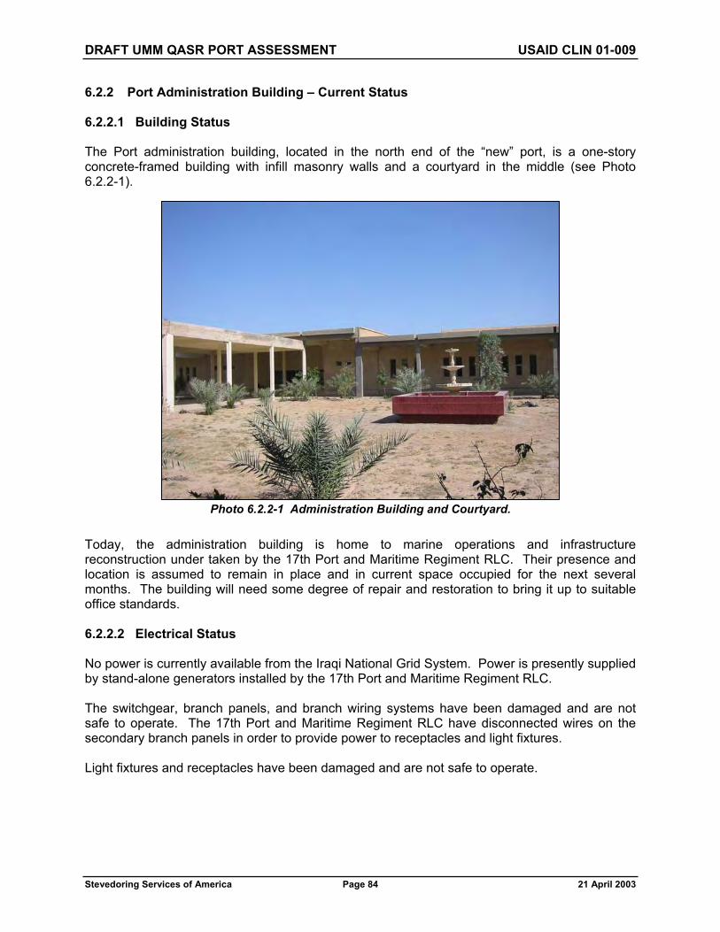
DRAFT UMM QASR PORT ASSESSMENT USAID CLIN 01-009
Stevedoring Services of America Page 84 21 April 2003
6.2.2 Port Administration Building – Current Status
6.2.2.1 Building Status
The Port administration building, located in the north end of the “new” port, is a one-story concrete-framed building with infill masonry walls and a courtyard in the middle (see Photo 6.2.2-1).
Today, the administration building is home to marine operations and infrastructure reconstruction under taken by the 17th Port and Maritime Regiment RLC. Their presence and location is assumed to remain in place and in current space occupied for the next several months. The building will need some degree of repair and restoration to bring it up to suitable office standards.
6.2.2.2 Electrical Status
No power is currently available from the Iraqi National Grid System. Power is presently supplied by stand-alone generators installed by the 17th Port and Maritime Regiment RLC.
The switchgear, branch panels, and branch wiring systems have been damaged and are not safe to operate. The 17th Port and Maritime Regiment RLC have disconnected wires on the secondary branch panels in order to provide power to receptacles and light fixtures.
Light fixtures and receptacles have been damaged and are not safe to operate.
Photo 6.2.2-1 Administration Building and Courtyard.

DRAFT UMM QASR PORT ASSESSMENT USAID CLIN 01-009
Stevedoring Services of America Page 85 21 April 2003
6.2.2.3 HVAC and Plumbing Systems Status
The building HVAC and plumbing systems are not operating. This is most likely due to the water system not operating.
6.2.3 Port Administration Building – Recommendations
6.2.3.1 Building Recommendations
Everything will need to be purchased in the way of office equipment and supplies, including but not limited to such things as furniture, faxes, copy machines, computers, printers, and traditional office needs such as pencils, pens, paper, staples, filing cabinets, etc. Within the administration building, a storage room with inventory control will be a requirement. Generator power packs to run lights, air conditioning, and traditional office equipment is a must.
Waste and refuse (nonhazardous) will also be controlled by the administrative staff. The assessment team did not observe or discover a local system for the proper disposal of nonhazardous waste and refuse. Some Kuwaiti contractors are being used by coalition forces to manage some waste and refuse, such as portable toilet administration. SSA will assume that previous local waste and refuse disposal management practices and policies may not be applicable, and that an environmentally sensitive system of nonhazardous commodity disposal (such as recycling and incineration where applicable) will be required.
Cost Estimate: US$750,000
6.2.3.2 Electrical Recommendations
Replace all electrical switchgear, branch panels, light fixtures, receptacles, and wiring in the building.
Cost Estimate: US$80,000
This building will require reliable back-up power. Until the normal and backup site electrical power systems are repaired, provide a 400 KW, 400v generator set with automatic transfer switch to power the building.
Cost Estimate: US$50,000
6.2.3.2 HVAC and Plumbing Systems Recommendations
All plumbing fixture hardware and any damaged porcelain fixtures need to be replaced.
Estimated Cost: US $20,000.
The HVAC equipment for the building will not be adequate when modern electronic equipment is operating in the building. This equipment needs to be replaced and the new equipment needs to be designed to handle the building load plus a future computer room (20 by 40 feet) heat load.
Estimated Cost: US$80,000.

DRAFT UMM QASR PORT ASSESSMENT USAID CLIN 01-009
Stevedoring Services of America Page 86 21 April 2003
6.3 COMMUNICATIONS
No obvious communications systems or equipment were found or in operable condition anywhere. SSA anticipates that reliable, real-time communications equipment and supporting hardware for the efficient and safe operation and administration of the Port will need to be supplied. Various modes of simultaneous communications media will be required to handle the voice and data workload 24 hours a day. Each mode of communication has its own specific capabilities and its own particular limitations. A summary of the most essential communications modes for the initial phase of Port management are as follows.
6.3.1 Ship-to-Shore Radio (VHF)/Maritime
A reliable, on-site radio network for ship-to-shore and harbor communications will be required for Port management responsibilities, such as: vessel traffic (harbor); control call-up and safety (i.e., Channel 16 marine band); vessel traffic control working frequencies (i.e., Channel 12 marine band); bridge-to-bridge communications (i.e., Channel 13 marine band); tugs, pilotage, and docking control (and line handlers); and marine broadcasts (notice to mariners, warnings, and Weather). Some of these responsibilities may be assumed by an Iraqi government agency (such as a coast guard), but SSA will assume that initial Port operations may need to address these requirements in the short term.
6.3.2 Ship-to-Shore Radio (HF)/Maritime
The same comments for 6.3.1 above may apply, although for the HF radio-frequency spectrum.
6.3.3 Shore-to-Shore Radio (UHF)/Operations
For safety reasons, a real-time UHF radio network will be essential during cargo handling operations (i.e., communications between a crane operator and a cargo supervisor to “lower away” or “hoist away”). This network will also handle command and logistical communications between vessel operations and yard operations.
6.3.4 Shore-to-Shore Operations (UHF)/Command and Administration
A reliable UHF radio network will also be required to handle all of the command and logistical communications to support cargo operations, such as equipment maintenance, employee transportation, and security/safety response.
Note on Radios. Prior to procuring any radios for communications, it is needed to determine what radio frequencies, carrier configuration, and transmitter power ceilings are locally available and/or allowed in the representative electromagnetic spectrum. Normally, a governmental agency or commission would adjudicate and approve a request for radio use based on proposed frequency, carrier, power of the transmitter, and operating area. There may be an Iraqi national network in place near the Port that would conflict with SSA’s proposed radio frequency plan. SSA suggests that any proposed electromagnetic spectrum use be reviewed and approved by an appropriate (competent/cognizant) authority until an Iraqi governmental agency or commission is established and in operation.

DRAFT UMM QASR PORT ASSESSMENT USAID CLIN 01-009
Stevedoring Services of America Page 87 21 April 2003
6.3.5 Telephones (Land-Line, Cellular, Satellite, Radio [i.e., Trunking] Telephones)
A reliable telephone system would be required to conduct the daily business of the Port, such as coordination with government agencies (e.g., customs, quarantine, and immigration), shipping and freight agents, labor contractors, and merchants. SSA also needs to determine what other options, such as the use of cellular telephones, satellite telephones, radio-telephones, or personal paging systems, are available and more importantly, reliable. This requirement should be anticipated and will need to be considered in the overall communication plan development (conduit and copper wire or fiber optic cable running) of the Port.
Note on Telephones. It is needed to initially determine if a local Iraqi land-line telephone exchange could support SSA’s land-line requirements (or determine when SSA can expect this system to be operational). SSA also needs it to be determined what other portable communications providers are available and operational in theater. SSA’s experience with international cellular telephones slaved to a Kuwait network provided limited reliability in the Port area during the assessment team’s visit.
6.3.6 Automated Information Systems (AIS)/Administration
A local area network for electronic data exchange of administrative and operational messages would be helpful, although not altogether essential for the initial phase of cargo operations. This requirement should be anticipated and will need to be considered in the overall communication plan development (conduit and fiber optic cable running) of the Port.
6.3.7 Automated Information Systems (AIS)/Security
Electronic security and alarm systems, such as access controllers (card reader and electric door strikes), CCTV, intrusion detectors, fire detectors, and barrier gates will also need a local area network for electronic data exchange. This requirement should be anticipated and will need to be considered in the overall communications plan development (conduit and fiber optic cable running) of the Port.
6.4 STORES
6.4.1 Current Status
Inspection of each facility suggested that the Port was equipped with spare parts warehouses in many different locations (see Photos 6.4.1-1 through 6.4.1-4). The grain terminal undoubtedly held the most substantial stock holding, having three large warehouses of material. Others, such as the engineering department in “old” and “new” ports, held only minor items of stock that appeared inadequate for the size of the operation. In each case, the stores areas had been ransacked, many parts damaged or completely destroyed Photo 6.4.1-1 Grain Elevator Terminal Store.

DRAFT UMM QASR PORT ASSESSMENT USAID CLIN 01-009
Stevedoring Services of America Page 88 21 April 2003
As discussed earlier, for the sake of cost saving and control, the concentration of operational activity will be focused upon the “new” port and, for this reason, it is proposed to maintain a centralized stockholding in this facility. Certain exceptions to this rule are proposed; the grain elevator terminal is quite remote, often requiring spare parts urgently and the inventory is substantial, of relatively high cost and bulky. The existing grain terminal is equipped with vast warehouse accommodation although space is not utilized very well. A review of the grain terminal spare parts storage is included within Section 4.1 along with a proposal for the upgrade.
No further consideration is provided within this section.
In a similar manner, the operation of a bulk-handling facility using vacuators on Berths 1 and 2 would justify the existence of a separate on-site spares stores and this is the proposal adopted here in the recommendations. Only a small stockholding of insurance and consumable parts is proposed.
In the “new” port there is a large variety of equipment, ranging from quay cranes to fork-lift trucks on the equipment side, but also water treatment plants and weighbridges on the site services inventory. Very little spare parts to support these facilities were discovered during our site investigation.
6.4.2 Recommendations
Create a small spare parts store in the warehouse of Berths 1 and 2 to support the mobile grain operation and the corresponding infrastructure. Equipment supported would include the Roncuzzi vacuators, trucks, and a front-end loader. It is suggested that the equipment manufacturers be approached to assist in defining the inventory required to support the
Photo 6.4.1-3 Spare Parts Store “Old” Port.
Photo 6.4.1-2 Lube Store at Grain Elevator Terminal, Flooded with Engine and Transmission Oils.

DRAFT UMM QASR PORT ASSESSMENT USAID CLIN 01-009
Stevedoring Services of America Page 89 21 April 2003
operation in Iraq where spares may not be readily available on the open market. The storage of spares would be provided by way of a lock-up freight container already available on the berth.
Cost Estimate: US$200,000
Within the “new” port, the engineering department will be the one consuming most of the spare parts, especially if the equipment maintenance and site services are consolidated within the one building as discussed in Section 6.1 of this report. For this reason, it is recommended that the main spare parts stores be incorporated within the maintenance building in order that issue of parts may be handled with minimum delay. A conveniently located area within the building already exists that may be converted for storage of consumables and frequently used equipment spares. A larger caged area is recommended for
storage of heavy materials, such as wire ropes and insurance spares like gearboxes, motors, and other items, that do not require environment control. The spares need to be identified and procured quickly, as it is the only way a port such as this can remain reliable while situated in a country where materials are likely to be in short supply.
This report also recommends that the stores be made totally secure with a closed-door policy, whereby only approved and accountable personnel are permitted entry. While it is fully acceptable to introduce a manual system of inventory control in the short term, it is recommended that an integrated computerized system be adopted in the future. The stores will also become the central point for goods receiving and the processing of Goods Received documentation.
Cost Estimate: building modifications, caged stores, and inventory to support a wide variety of equipment including cranes, tractors, trailers, vehicles, and site services: US$3 Million.
6.5 FUEL
6.5.1 Current Status
Reliable fuel supplies and associated safe storage facilities are fundamental to the operation of any marine port. In Umm Qasr, most of the mobile landside cargo handling equipment, such as tractors, container lifters, and forklift trucks, depend up on a steady supply of fuel for their power. Similarly, the waterside operations and maintenance depend upon fuel as an energy source to power dredgers, tug boats, survey vessels, and pilot boats.
Photo 6.4.1-4 Spare Parts Store “New” Port.
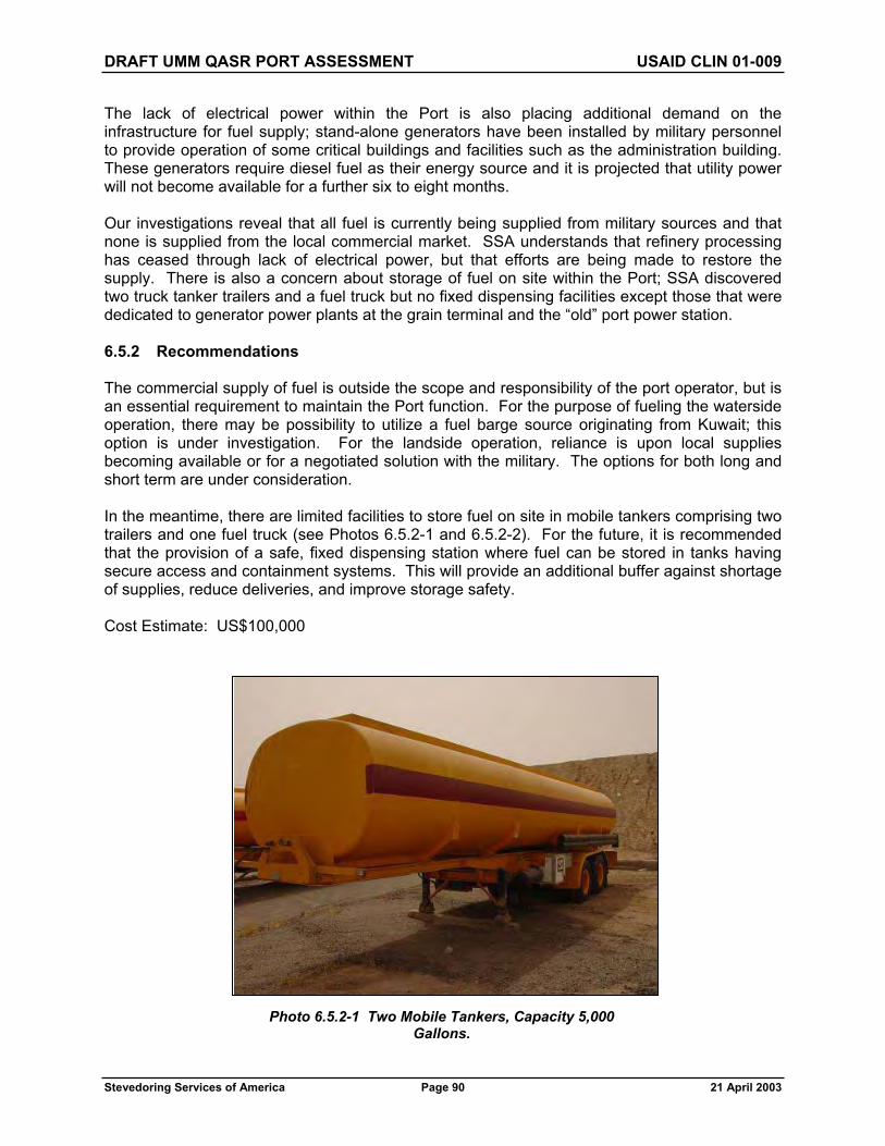
DRAFT UMM QASR PORT ASSESSMENT USAID CLIN 01-009
Stevedoring Services of America Page 90 21 April 2003
The lack of electrical power within the Port is also placing additional demand on the infrastructure for fuel supply; stand-alone generators have been installed by military personnel to provide operation of some critical buildings and facilities such as the administration building. These generators require diesel fuel as their energy source and it is projected that utility power will not become available for a further six to eight months.
Our investigations reveal that all fuel is currently being supplied from military sources and that none is supplied from the local commercial market. SSA understands that refinery processing has ceased through lack of electrical power, but that efforts are being made to restore the supply. There is also a concern about storage of fuel on site within the Port; SSA discovered two truck tanker trailers and a fuel truck but no fixed dispensing facilities except those that were dedicated to generator power plants at the grain terminal and the “old” port power station.
6.5.2 Recommendations
The commercial supply of fuel is outside the scope and responsibility of the port operator, but is an essential requirement to maintain the Port function. For the purpose of fueling the waterside operation, there may be possibility to utilize a fuel barge source originating from Kuwait; this option is under investigation. For the landside operation, reliance is upon local supplies becoming available or for a negotiated solution with the military. The options for both long and short term are under consideration.
In the meantime, there are limited facilities to store fuel on site in mobile tankers comprising two trailers and one fuel truck (see Photos 6.5.2-1 and 6.5.2-2). For the future, it is recommended that the provision of a safe, fixed dispensing station where fuel can be stored in tanks having secure access and containment systems. This will provide an additional buffer against shortage of supplies, reduce deliveries, and improve storage safety.
Cost Estimate: US$100,000
Photo 6.5.2-1 Two Mobile Tankers, Capacity 5,000 Gallons.

DRAFT UMM QASR PORT ASSESSMENT USAID CLIN 01-009
Stevedoring Services of America Page 91 21 April 2003
Photo 6.5.2-2 Mobile Fuel Truck, Condition Unknown, not Yet Assessed.

DRAFT UMM QASR PORT ASSESSMENT USAID CLIN 01-009
Stevedoring Services of America Page 92 21 April 2003
SECTION 7.0 — TRANSPORTATION
7.1 ROADWAYS
7.1.1 General
The Port of Umm Qasr has road links northwest to Al Basrah and other population centers in northern Iraq, and south across the international border into Kuwait. These roadways are generally paved with asphalt concrete, consist of both two- and four-lane sections, and currently accommodate all vehicular cargo traffic into and out of the Port of Umm Qasr. See Figure 7.1
Primary segments of the port (i.e., “new” port, “old” port, grain elevator, etc.) must be accessed by circulation roads external to the Port. Internal access roads between the “old” and “new” ports currently do not exist.
7.1.2 “New” Port
7.1.2.1 Condition Assessment
The internal roadway system consists mostly of two-lane, asphalt-paved roads that are in reasonably good condition. Existing concrete bridges that carry an internal circulation road over railroad tracks at the north end of the “new” port also appear to be in satisfactory condition (see Photo 7.1.2.1-1). Vehicular access to berthing areas and storage warehouses is readily available. Exterior circulation roads appear adequate for queuing of trucks awaiting access to the “new” port.
Two entrances provide vehicle ingress and egress to the “new” port, neither of which has gated access control. The north gate has been temporarily blocked with cargo containers by the 17th Port and Maritime Regiment R.L.C. for security purposes (see Photo 7.1.2.1-2). Primary access to the “new” port appears to be through the west gate, which is currently controlled by military security forces. There is a gate house, scale house, two electrical vehicle weighbridges, and inspection platforms located at the west gate (see Photo 7.1.2.1-3).
Photo 7.1.2.1-1 Existing Concrete Bridge Over Railroad Tracks.

N
Umm Qasr Port Assessment: Port Transportation Features - Figure 7.1
* Not to scale, modified to fit sheet
Train Station
IRAQKUWAIT
IRAQKUWAIT
Rail Entranceto "New" Port "New" Port
North Entry Gate
"New" PortFire Station
Entry Gate atGrain Elevator
"Old" PortNorth EntryGate
"Old" PortFire Station
"Old" PortSouth Entry
Gate
Existing BridgeOver Railroad
"New" PortWest Entry Gate
Road to Al Basrah
Rail Entrance toGrain Elevator
KHAWR
AZZUBAYR
KHAWR
AZZUBAYR
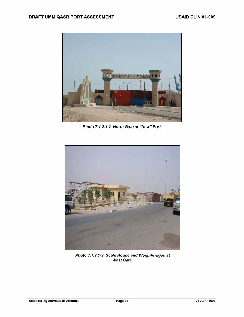
DRAFT UMM QASR PORT ASSESSMENT USAID CLIN 01-009
Stevedoring Services of America Page 94 21 April 2003
Photo 7.1.2.1-3 Scale House and Weighbridges at West Gate.
Photo 7.1.2.1-2 North Gate at “New” Port.

DRAFT UMM QASR PORT ASSESSMENT USAID CLIN 01-009
Stevedoring Services of America Page 95 21 April 2003
7.1.2.2 Recommendations
The internal roadway system within the “new” port appears adequate, and should only require minor repairs due to some potholing. During port operations, a regular roadway maintenance program should be implemented to repair roadways on an as-needed basis.
The cost to complete repairs to the roadway system in the “new” port is estimated to be US$50,000.
Existing cargo containers that block the north gate should be removed and a permanent movable security barrier installed to allow opening or closing the gate as necessary for changing access needs during Port operations. Security barriers should also be installed at the west gate to allow emergency closure of the gate if necessary.
Costs for installing permanent movable security barriers at both north and west gates are estimated to be US$100,000.
7.1.3 “Old” Port
7.1.3.1 Condition Assessment
The roadway system at the “old” port also consists of asphalt-paved two-lane roads in fair condition that provide adequate access to berthing areas and storage warehouses. No bridges or major restrictions to vehicle circulation appear to exist within the “old” port.
Two entrances provide vehicle ingress and egress to the “old” port from circulation roads outside of the Port. The south gate has been temporarily blocked with cargo containers by the 17th Port and Maritime Regiment R.L.C. for security purposes. Primary access to the “old” port appears to be through the north gate, which is currently controlled by military security forces (see Photo 7.1.3.1-1). There are several structures at the north gate that have been damaged by unknown causes and will require repair. Exterior circulation roads appear adequate for queuing of trucks awaiting access to the “old” port.
7.1.3.2 Recommendations
Any minor repairs to the internal roadway system should be completed and a regular roadway maintenance program developed and implemented to repair roadways on an as-needed basis during Port operations.
Photo 7.1.3.1-1 North Gate at “Old” Port.
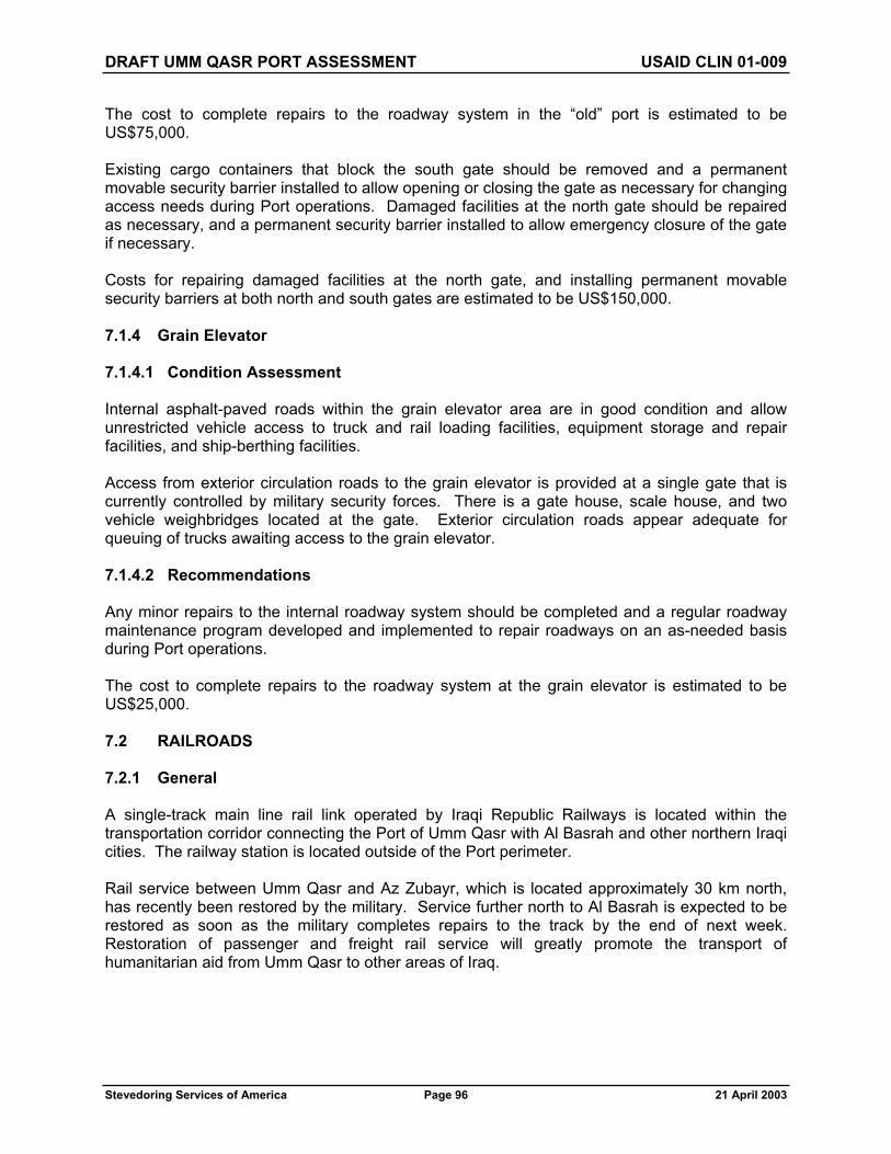
DRAFT UMM QASR PORT ASSESSMENT USAID CLIN 01-009
Stevedoring Services of America Page 96 21 April 2003
The cost to complete repairs to the roadway system in the “old” port is estimated to be US$75,000.
Existing cargo containers that block the south gate should be removed and a permanent movable security barrier installed to allow opening or closing the gate as necessary for changing access needs during Port operations. Damaged facilities at the north gate should be repaired as necessary, and a permanent security barrier installed to allow emergency closure of the gate if necessary.
Costs for repairing damaged facilities at the north gate, and installing permanent movable security barriers at both north and south gates are estimated to be US$150,000.
7.1.4 Grain Elevator
7.1.4.1 Condition Assessment
Internal asphalt-paved roads within the grain elevator area are in good condition and allow unrestricted vehicle access to truck and rail loading facilities, equipment storage and repair facilities, and ship-berthing facilities.
Access from exterior circulation roads to the grain elevator is provided at a single gate that is currently controlled by military security forces. There is a gate house, scale house, and two vehicle weighbridges located at the gate. Exterior circulation roads appear adequate for queuing of trucks awaiting access to the grain elevator.
7.1.4.2 Recommendations
Any minor repairs to the internal roadway system should be completed and a regular roadway maintenance program developed and implemented to repair roadways on an as-needed basis during Port operations.
The cost to complete repairs to the roadway system at the grain elevator is estimated to be US$25,000.
7.2 RAILROADS
7.2.1 General
A single-track main line rail link operated by Iraqi Republic Railways is located within the transportation corridor connecting the Port of Umm Qasr with Al Basrah and other northern Iraqi cities. The railway station is located outside of the Port perimeter.
Rail service between Umm Qasr and Az Zubayr, which is located approximately 30 km north, has recently been restored by the military. Service further north to Al Basrah is expected to be restored as soon as the military completes repairs to the track by the end of next week. Restoration of passenger and freight rail service will greatly promote the transport of humanitarian aid from Umm Qasr to other areas of Iraq.

DRAFT UMM QASR PORT ASSESSMENT USAID CLIN 01-009
Stevedoring Services of America Page 97 21 April 2003
7.2.2 “New” Port
7.2.2.1 Condition Assessment
The existing rail system provides rail access to all ship berthing/unloading areas and storage warehouses within the port (see Photo 7.2.2.1-1). Although the track appears to be in reasonable condition, it has been poorly maintained and will require some repair of rail, operating switches, and vehicle crossings.
Two shunting locomotives that are located in the “new” port have been made operational by the military (see Photo 7.2.2.1-2). One Chinese-made main line locomotive was also towed into the “new” port, but currently is not operational. Examination of the main line engine by the military indicates that it is in good condition, but factory refurbishment may be necessary to make it fully operational. Approximately 18 flat cars and 5 hopper cars have also been stored within the “new” port for security. The military indicated that a large supply of rolling stock has been stored at a rail yard located west of Al Basrah and may become available for use after rail service is fully restored.
One railroad entrance with gated access control is located on the north side of the “new” port (see Photo 7.2.2.1-3).
Photo 7.2.2.1-1 Rail Spur at “New” Port.
Photo 7.2.2.1-2 Shunting Locomotive.

DRAFT UMM QASR PORT ASSESSMENT USAID CLIN 01-009
Stevedoring Services of America Page 98 21 April 2003
Rail car loading ramps are located at each storage warehouse and at several locations within the container storage yard (see Photo 7.2.2.1-4). All appear to be in good condition and usable.
7.2.2.2 Recommendations
All onsite railroad tracks should be tested for soundness and repaired or replaced as necessary. Maintenance and repair of operating switches, other moving parts of the rail system, and electronic controls should be completed, and any damaged vehicle crossings repaired.
Costs for testing and repair of rail facilities at the “new” port are estimated to be US$600,000.
Photo 7.2.2.1-4 Warehouse Loading Ramp at “New” Port.
Photo 7.2.2.1-3 Rail Entry at “New” Port.

DRAFT UMM QASR PORT ASSESSMENT USAID CLIN 01-009
Stevedoring Services of America Page 99 21 April 2003
7.2.3 “Old” Port
7.2.3.1 Condition Assessment
Rail access to ship berths, grain unloading areas, and storage warehouses is adequate at the “old” port. At least five rail spurs extend through the perimeter security barrier around the “old” port, several of which have been blocked with cargo containers by the military for security purposes (see Photo 7.2.3.1-1). Most of the railroad track within the “old” port appears to be usable, but is in a state of neglect and disrepair. Some portions of the rail system serving Berths 1 and 2 are missing and will require replacement.
Rail car loading ramps are located at storage warehouses (see Photo 7.2.3.1-2). All appear to be in fair condition and usable.
7.2.3.2 Recommendations
All onsite railroad tracks should be tested for soundness and repaired or replaced as necessary. Maintenance and repair of operating switches, other moving parts of the rail system, and electronic controls should be performed, and any damaged vehicle crossings repaired.
Costs for testing and repair of rail facilities at the “old” port are estimated to be US$800,000.
Existing cargo containers that are currently blocking the rail entrances should be removed and permanent movable security barriers installed at entrances without existing security gates to allow opening or closing of the rail spur as necessary for security purposes during port operations.
The cost of installing permanent removable security barriers at the five rail entrances into the “old” port is estimated to be US$250,000.
Photo 7.2.3.1-2 Warehouse Loading Ramps at “Old” Port.
Photo 7.2.3.1-1 Rail Entry at “Old” Port.

DRAFT UMM QASR PORT ASSESSMENT USAID CLIN 01-009
Stevedoring Services of America Page 100 21 April 2003
7.2.4 Grain Elevator
7.2.4.1 Condition Assessment
A rail spur and sidings are provided for loading of grain from the elevator into rail cars. Some of the railroad track is damaged or missing and will require repair, but most appears usable. Railway entrances are located at the east and west perimeters of the site, neither of which are access controlled.
7.2.4.2 Recommendations
All onsite railroad tracks should be tested for soundness and repaired or replaced as necessary. Maintenance of operating switches and other moving parts of the rail system should be performed, and any damaged vehicle crossings repaired.
Costs for testing and repair of rail facilities at the grain elevator are estimated to be US$250,000.
Permanent movable security barriers should be installed at each of the railway entrances to allow opening or closing of the rail spur as necessary for security purposes during Port operations.
The cost of installing permanent removable security barriers at the rail entrances into the grain elevator site is estimated to be US$100,000.
7.3 AIR
7.3.1 General
The nearest operating airfield is Al Basrah International Airfield, located 65 km northwest of the Port of Umm Qasr. An abandoned airfield that bisects the international border between Iraq and Kuwait is located south of Umm Qasr. Adequate helicopter landing sites are be available at the “new” and “old” portions of the Port of Umm Qasr that could be used for air medivac.
As there are no air cargo transport facilities located near the Port of Umm Qasr, no further consideration of air cargo transportation will be included in this analysis.
7.4 INLAND WATERWAYS
7.4.1 General
The Khawr Az Zubayr waterway extends approximately 17.6 km up river from the Port of Umm Qasr. Evaluation of the port facilities at Az Zubayr and inland waterways is beyond the scope of this analysis.

DRAFT UMM QASR PORT ASSESSMENT USAID CLIN 01-009
Stevedoring Services of America Page 101 21 April 2003
SECTION 8.0 — UTILITIES
8.1 HIGH VOLTAGE ELECTRICAL
8.1.1 Iraqi National Grid Substations
8.1.1.1 Condition Assessment
Bulk electrical power for the Port of Umm Qasr area is received from the Iraqi National Grid transmission system at 132 KV.
There are two separate transmission system substations: one for the old port area and one for the new port, grain elevator, Town of Umm Qasr, and the UN Compound. The transmission system substation at the new port steps the voltage down to 33KV for distribution to the grain elevator and down to 11KV for distribution to the new port area, Town of Umm Qasr, and UN Compound. The transmission system substation for the old port area steps the voltage down to 11KV for distribution throughout the old port area. See Figure 8.1.
The Iraqi National Grid has been damaged and is currently not transmitting electricity over the 132KV transmission lines. Repair and re-energization of the Iraqi National Grid is unknown at this time but estimated to be several months.
The 33KV and 11KV substation switchgear located at the old port area and new port area substations for the Port of Umm Qasr have been damaged and currently are disconnected from the Iraqi National Grid.
8.1.1.2 Recommendations
Substation switching equipment needs replacement and existing 63 MVA transformers need maintenance prior to re-energization of normal power for the Port of Umm Qasr area from the Iraqi National Grid.
Cost Estimate: US$2,000,000
8.1.2 New Port Area
8.1.2.1 Condition Assessment
8.1.2.1.1 Normal Power
Distribution of normal power to the new port Area is at 11KV, originating at the new port area, Iraqi National Grid Substation. This power source is currently disconnected and needs replacement prior to renergization of normal power in the new port area.
8.1.2.1.2 Backup Power
Currently backup power to the new port Area is not available. The British have disconnected the secondary distribution systems for individual buildings at switchboards and provided individual generators to power buildings where necessary.

N
Umm Qasr Port Assessment: Port Utility Features - Figure 8.1
* Not to scale, modified to fit sheet
KHAWR
AZZUBAYR
KHAWR
AZZUBAYR
IRAQKUWAIT
IRAQKUWAIT
Water TowerReservoir
Water Pump Station
ElectricalSubstations
Umm Qasr MunicipalWater Supply andTreatment Facility
Generator FarmSupplying Town
of Umm Qasrand Un Compound
Electrical Switchgear
33KV Substation
Water PumpStation andReservoir
ElectricalSubstationTypical of6 In "Old" Port
Water PumpStations
Generator Building
(2) 2.5 MWGenerators
GeneratorBuilding
ElectricalSubstation
132KVTransmission
Substation(2) 63 MVA
Transformers
Road to Al Basrah

DRAFT UMM QASR PORT ASSESSMENT USAID CLIN 01-009
Stevedoring Services of America Page 103 21 April 2003
The original design for backup power was a single building that has space for two generator sets. These generators have been removed.
The Customs building located near the RO/RO berth and the Water System(s) building are the exceptions to the new port area backup power system. The electrical service for these buildings consists of stand alone generators. These generators have damage and need replacement.
Photo 8.1.2.1.2-2 Generator.
Photo 8.1.2.1.2-1 Generator Building.

DRAFT UMM QASR PORT ASSESSMENT USAID CLIN 01-009
Stevedoring Services of America Page 104 21 April 2003
8.1.2.1.3 11KV Cable/Switchgear/Transformers
The 11KV Cable/Switchgear/ Transformers are all over 20 years old. Switchgear and 11KV cable has been damaged. Transformers are low on oil and some show signs of leakage.
8.1.2.2 Recommendations
All 11KV cable, switchgear, and transformers are past their useful life and need to be replaced to safely operate the new port area on a permanent basis.
Cost Estimate: US$3,000,000
Two new 1.5MW, 400v backup generators with 400v to 11KV step up transformers need to be provided for minimal backup power when normal power from the Iraqi National Grid is not available.
Cost Estimate: US$650,000
New 150KW back up generators need to be provided for the Customs and Water services buildings.
Cost Estimate: US$75,000
8.1.3 Grain Facility
8.1.3.1 Conditional Assessment
8.1.3.1.1 Normal Power
Distribution of normal power to the grain elevator is at 33KV originating at the new port area, Iraqi National Grid Substation. This power source is currently disconnected and needs replacement prior to energization.
At the grain elevator, the 33KV is transformed to 3.3KV for distribution to the elevator equipment and evacuators. The 3.3KV is transformed down to 400v, 1000KVA for secondary distribution to all the ancillary buildings and the grain elevator. The 3.3KV is transformed on the evacuator dock to 400v, 1000KVA for secondary distribution on the dock.
8.1.3.1.2 Backup Power
Backup power for the grain elevator and evacuator dock is currently supplied from two, 2.5MW, 3.3KV, parralled generators. These generators are 20-plus years old. The British have been unable to get generator No. 1 started and were in the process of performing a major overhaul on
Photo 8.1.2.1.2-3 Switch Gear.

DRAFT UMM QASR PORT ASSESSMENT USAID CLIN 01-009
Stevedoring Services of America Page 105 21 April 2003
generator No. 2 to make it operational. They have since abandoned the attempt to refurbish either of the generators and are in the process of getting a new 2.5MW, 3.3KV generator.
If the grain elevator, ancillary buildings, and vacuators are run on a limited basis (75 percent capacity) one generator will be sufficient to operate the system. However, this will not be a reliable source of electrical power due to the age of the equipment. There was a 400KW (500KVA), 400v, (722 amp) generator on the evacuator dock for the fire protection system. This generator has been removed and requires replacement.
The support buildings at the grain terminal receive backup power from a 400KW (500KVA), 400v, (722 amps) Cummins generator. This generator has been stripped of batteries and other parts. This is a fairly new piece of equipment and can probably be operational with new parts and maintenance. Currently, the British have provided a separate portable generator at this location to operate and test systems.
Photo 8.1.3.1.2-2 Generator.
Photo 8.1.3.1.2-1 Generator Building.

DRAFT UMM QASR PORT ASSESSMENT USAID CLIN 01-009
Stevedoring Services of America Page 106 21 April 2003
8.1.3.1.3 33KV/3.3KV Cable/ Switchgear/Transformers
The 33 KV System has been disconnected. There are several reels of 33 KV cable stored onsite. Status of these cables is unknown. There is visual damage to the outer jacket of the cable on one of the reels and the jacket color has been bleached out from exposure to the sun. It is not clear or evident if the existing 33 KV cable has failed in the past but it is probably original (over 20 years old) and near the end of rated life.
The 33KV and 3.3KV switchgear appears undamaged and operational.
All transformers are over 20 years old.
8.1.3.2 Recommendations
The existing 33KV, 3.3 KV cables, switchgear, and transformers are over 20 years old and are recommended for replacement to safely operate the grain facility on a long term and permanent basis.
Cost Estimate: US$1,200,000
The above US$1,200,000 estimate could be reduced by US$200,000 if the existing 33KV cable onsite is determined to be usable after high pot testing.
Replace the two existing 2.5MW, 3.3KV generators, switchgear, and one 400KW, 400v generator set to
provide reliable power to the grain facility until the normal source of power from the Iraqi National Grid can be restored.
Cost Estimate: US$970,000
Photo 8.1.3.1.3-1 33KV Cable Reels.
Photo 8.1.3.1.2-3 Generator.

DRAFT UMM QASR PORT ASSESSMENT USAID CLIN 01-009
Stevedoring Services of America Page 107 21 April 2003
8.1.4 Old Port Area
8.1.4.1 Condition Assessment
8.1.4.1.1 Normal Power
Distribution of normal power to the old port area is 11KV originating at the old port Iraqi National Grid Substation. This power source is currently disconnected and needs replacement prior to re-energization of normal 11KV power in the old port area.
8.1.4.1.2 Backup Power
Currently backup power to the old port area is not available. The British have disconnected the secondary distribution systems for individual buildings at switchboards and have provided individual generators to power buildings where necessary.
The original design for 11KV backup power was a single building that has space for two generator sets. These generators have been removed.
8.1.4.1.3 11KV Cable/ Switchgear/Transformers
The 11KV cable system is damaged at several locations.
All switchgear and transformers are over 40 years old and past their useful life.
Photo 8.1.4.1.3-1 11KV Cable.
Photo 8.1.4.1.1-1 Generator Building.

DRAFT UMM QASR PORT ASSESSMENT USAID CLIN 01-009
Stevedoring Services of America Page 108 21 April 2003
8.1.4.2 Recommendations
All 11KV cable, switchgear, and transformers need replacement for safe operation of the old port area electrical system on a permanent basis.
Cost Estimate: US$4,000,000
Two new 1.5 MW, 400v, backup generators with 400v to 11KV step up transformers need to be provided for minimal backup power when normal power from the Iraqi National Grid is not available.
Cost Estimate: US$650,000
A new 400 KW backup generator, automatic transfer switch, and switchgear needs to be provided for the two Water Service buildings.
Cost Estimate: US$50,000
8.1.5 Sugar and Vegetable Oil Facility
8.1.5.1 Condition Assessment
A condition assessment of this facility was not performed. This facility is not part of SSA’s scope of work.
8.1.5.2 Recommendations
None.
8.1.6 Cement Facility
8.1.6.1 Condition Assessment
A condition assessment of this facility was not performed. This facility is not part of SSA’s scope of work.
8.1.6.2 Recommendations
None.
8.1.7 Umm Qasr/UN Compound
8.1.7.1 Condition Assessment
Photo 8.1.4.1.3-2 11KV Switch Gear.

DRAFT UMM QASR PORT ASSESSMENT USAID CLIN 01-009
Stevedoring Services of America Page 109 21 April 2003
8.1.7.1.1 Normal Power
Distribution of normal power to the town of Umm Qasr and the UN Compound is at 11KV originating at the new port area Iraqi National Grid Substation. This power source is currently disconnected.
8.1.7.1.2 Backup Power
The town of Umm Qasr and the UN Compound currently receive backup power from a 12MW generator farm located at the grain elevator. These generators are less than two (2) years old and have an automatic paralleling system. The British have not been able to find the PC operating program for the automatic paralleling system and are attempting to contact the original equipment supplier to obtain information for full operation of the system. The British currently have two generators paralleled and the peak operating load has not exceeded 2.2MW.
8.1.7.1.3 11 KV Cable/Transformers/Switchgear
No assessment of these systems was performed as they are not related to SSA operations.
8.1.7.2 Recommendations
Repair of this equipment is not required to receive humanitarian aid through the Port of Umm Qasr.
8.2 WATER SYSTEM
8.2.1 General
Potable water is piped from Al Basrah to supply the existing water distribution system in Umm Qasr, which includes a water tower reservoir and water treatment facilities. The water supply pipeline was shut down at an existing pumping station located north of Umm Qasr during the recent military action in Iraq and remained inactive until recently. Military efforts to reestablish this water supply apparently were successful, resulting in the reactivation of potable water service in Umm Qasr. A temporary potable water supply pipeline was constructed across the Kuwait/Iraq international border by the Kuwait government during the military conflict in Iraq, with a network of distribution sites located in Umm Qasr to serve the civilian population until local water service could be restored. Potable water for the military is currently being produced by a portable reverse osmosis treatment system set up in the new port.
The water supply from Al Basrah is believed to be brackish and non-potable by U.S. standards. The existing water treatment facility in Umm Qasr includes chlorination equipment that is in poor condition. The treatment facility appears to be inoperable, and may have served only as a pumping station in the past. Possible UN restrictions on the import of materials such as chlorine may have contributed to the non-use of the water treatment system.
Each facility at the port (i.e., new port, old port, grain elevator, etc.) appears to have a potable water system that is connected by separate supply line to the water distribution facilities in Umm Qasr. Independent emergency fire suppression systems with intake facilities that draw sea water from adjacent waterways for fire fighting purposes are also located at each Port facility. See Figure 8.1.

DRAFT UMM QASR PORT ASSESSMENT USAID CLIN 01-009
Stevedoring Services of America Page 110 21 April 2003
It is important to note that no records of the water system could be found during SSA’s investigation of the Port facilities. Much of the general information regarding the existing water systems has been obtained from the military during SSA’s limited field reconnaissance of the Port.
8.2.2 “New” Port
8.2.2.1 Potable Water System Condition Assessment
The potable water system at the new port is supplied by the municipal water system in Umm Qasr and includes a separate water tower reservoir and pump station (see Photo 8.2.2.1-1). The system serves the Administration and other support buildings, several restroom facilities located throughout the grounds, and shipping berths within the new port. The water system is currently inactive due to lack of electric power in the region.
Water lines for supplying potable water to ships berthed at the new port are located in a dockside utilidor incorporated into the existing wharf structure. Metered ship service connections are located along the wharf, spaced approximately 100 meters apart (see Photo 8.2.2.1-2). Information obtained from discussions with local port workers during SSA’s field investigation suggests that cargo ships berthed at the Port routinely refused to connect to the water supply due to contamination of the potable water system.
Photo 8.2.2.1-1 Water Tower at New Port.
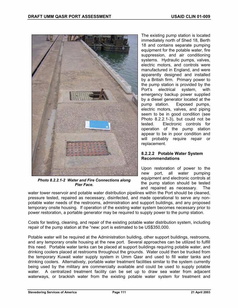
DRAFT UMM QASR PORT ASSESSMENT USAID CLIN 01-009
Stevedoring Services of America Page 111 21 April 2003
The existing pump station is located immediately north of Shed 18, Berth 18 and contains separate pumping equipment for the potable water, fire suppression, and air conditioning systems. Hydraulic pumps, valves, electric motors, and controls were manufactured in England, and were apparently designed and installed by a British firm. Primary power to the pump station is provided by the Port’s electrical system, with emergency backup power supplied by a diesel generator located at the pump station. Exposed pumps, electric motors, valves, and piping seem to be in good condition (see Photo 8.2.2.1-3), but could not be tested. Electronic controls for operation of the pump station appear to be in poor condition and will probably require repair or replacement.
8.2.2.2 Potable Water System Recommendations
Upon restoration of power to the new port, all water pumping equipment and electronic controls at the pump station should be tested and repaired as necessary. The
water tower reservoir and potable water distribution pipelines within the Port should be cleaned, pressure tested, repaired as necessary, disinfected, and made operational to serve any non-potable water needs of the restrooms, administration and support buildings, and any proposed temporary onsite housing. If operation of the existing water system becomes necessary prior to power restoration, a portable generator may be required to supply power to the pump station.
Costs for testing, cleaning, and repair of the existing potable water distribution system, including repair of the pump station at the “new: port is estimated to be US$350,000.
Potable water will be required at the Administration building, other support buildings, restrooms, and any temporary onsite housing at the new port. Several approaches can be utilized to fulfill this need. Portable water tanks can be placed at support buildings requiring potable water, and drinking coolers placed at restrooms throughout the grounds. Water could then be trucked from the temporary Kuwait water supply system in Umm Qasr and used to fill water tanks and drinking coolers. Alternatively, portable water treatment facilities similar to the system currently being used by the military are commercially available and could be used to supply potable water. A centralized treatment facility can be set up to draw sea water from adjacent waterways, or brackish water from the existing potable water system for treatment and
Photo 8.2.2.1-2 Water and Fire Connections along Pier Face.

DRAFT UMM QASR PORT ASSESSMENT USAID CLIN 01-009
Stevedoring Services of America Page 112 21 April 2003
distribution by truck or temporary pipeline to the various service points. If desired, smaller treatment systems that draw water directly from the existing water distribution system can be set up at various service points where water demand is large. The final potable water distribution plan for the new port should probably incorporate a combination of the methods discussed herein.
The cost for installing a temporary potable water treatment system at the “new” port is estimated to be US$150,000.
8.2.2.3 Fire Suppression System Condition Assessment
The fire suppression system at the new port is separate from the potable water system, and utilizes sea water supplied by intake facilities within the adjacent waterway. The location and condition of the intake facilities could not be determined during this Port assessment. Fire water lines serving the berthing areas are located in a dockside utilidor incorporated into the existing wharf structure. Fire hose connections are located along the wharf, spaced approximately 100 meters apart. In addition to the fire suppression facilities serving the shipping berths, at least one of the Port’s operational tugs has onboard fire fighting equipment.
No fire hydrants were found within the new port compound, and storage warehouses were not equipped with fire suppression systems. However, one of the support buildings on the grounds is a fire station (see Photo 8.2.2.3-1). Existing fire fighting equipment found at the site appears to be in operating condition, and includes a relatively new fire truck (see Photo 8.2.2.3-2) and a water tanker truck (see Photo 8.2.2.3-3).
Photo 8.2.2.1-3 Pump Station at the “New” Port.

DRAFT UMM QASR PORT ASSESSMENT USAID CLIN 01-009
Stevedoring Services of America Page 113 21 April 2003
Photo 8.2.2.3-1 Fire Station at New Port.
Photo 8.2.2.3-2 Fire Truck.

DRAFT UMM QASR PORT ASSESSMENT USAID CLIN 01-009
Stevedoring Services of America Page 114 21 April 2003
8.2.2.4 Fire Suppression System Recommendations
Upon restoration of power to the new port, all water pumping equipment and electronic controls at the pump station should be tested and repaired as necessary. Water intakes should be inspected and repaired if necessary. Fire water distribution pipelines within the Port should be cleaned, pressure tested, repaired as necessary, and made operational. If operation of the existing water system becomes necessary prior to power restoration, a portable generator may be required to supply power to the pump station.
Costs for testing, cleaning, and repair of the existing fire suppression system, including repair of the pump station at the new port is estimated to be US$250,000.
To provide fire protection for support buildings, storage warehouses, and other emergency needs, the existing fire station should be renovated and equipped with adequate fire fighting equipment.
The cost to renovate and equip the fire station at the new port is estimated to be US$150,000.
8.2.3 “Old” Port
8.2.3.1 Potable Water System Condition Assessment
The potable water system at the old port is supplied by the municipal water system in Umm Qasr and includes a dedicated pump station. The system serves onsite support buildings, several restroom facilities located throughout the grounds, and shipping berths within the old port. The system is currently inactive due to lack of power in the region.
Water lines for supplying potable water to ships berthed at the old port are located in a dockside utilidor incorporated into the existing wharf structure.
Photo 8.2.3.1-1 Pump Station at Old Port.
Photo 8.2.2.3-3 Water Tanker Truck.

DRAFT UMM QASR PORT ASSESSMENT USAID CLIN 01-009
Stevedoring Services of America Page 115 21 April 2003
Metered ship service connections are located along the wharf, spaced approximately 100 meters apart. Information obtained from discussions with local Port workers during SSA’s field investigation suggests that cargo ships berthed at the Port routinely refused to connect to the water supply due to contamination of the potable water system.
Two existing pump stations is located immediately north of Berth 2 contain pumping equipment for separate potable water and fire suppression systems (see Photo 8.2.3.1-1). Hydraulic pumps, pump motors, and valves appear to be old and in poor condition. Primary power to each pump station is provided by the Port’s electrical system. One of the fire system pumps is driven by a diesel motor, apparently to serve as an emergency backup. Exposed pumps, electric motors, valves, and piping could not be tested. Electronic controls for operation of the pump station appear to be missing or in very poor condition, and will require repair or replacement (see Photo 8.2.3.1-2).
8.2.3.2 Potable Water System Recommendations
Upon restoration of power to the old port, all water pumping equipment and electronic controls at the pump station should be tested and repaired as necessary. Potable water distribution pipelines within the Port should be cleaned, pressure tested, repaired as necessary, disinfected and made operational to serve any non-potable water needs of the restrooms and support buildings. If operation of the existing water system becomes necessary prior to power restoration, a portable generator may be required to supply power to the pump station.
Costs for testing, cleaning, and repair of the existing potable water system, including repair of the pump station at the old port is estimated to be US$200,000.
Potable water will be required at support buildings and several restrooms located throughout the old port. Several approaches can be utilized to fulfill this need. Portable water tanks can be placed at support buildings requiring potable water, and drinking coolers placed at restrooms throughout the grounds. Water could then be trucked from the temporary Kuwait water supply system in Umm Qasr and used to fill water tanks and drinking coolers. Alternatively, portable water treatment facilities similar to the system currently being used by the military at the new port are commercially available and could be used to supply potable water. A centralized treatment facility can be set up to draw sea water from adjacent waterways, or brackish water from the existing potable water system for treatment and distribution by truck or temporary pipeline to the various service points. If desired, smaller treatment systems that draw water directly from the existing water distribution system can be set up at various service points where water demand is large. The final potable water distribution plan for the old port should probably incorporate a combination of the methods discussed herein.
Photo 8.2.3.1-2 Pump Station Controls.

DRAFT UMM QASR PORT ASSESSMENT USAID CLIN 01-009
Stevedoring Services of America Page 116 21 April 2003
The cost for installing a temporary potable water treatment system at the “old” port is estimated to be US$100,000.
8.2.3.3 Fire Suppression System Condition Assessment
The fire suppression system at the old port is separate from the potable water system, and utilizes sea water supplied by intake facilities within the adjacent Khawr Az Zubayr waterway. The location and condition of the intake facilities could not be determined during this Port assessment. Fire water lines serving the berthing areas are located in a dockside utilidor incorporated into the existing wharf structure. Fire hose connections are located along the wharf in below-deck vaults, spaced approximately 50 meters apart. In addition to the fire suppression facilities serving the shipping berths, at least one of the Port’s operational tugs has onboard fire fighting equipment.
No fire hydrants were found within the old port compound, and storage warehouses were not equipped with fire suppression systems. However, one of the support buildings on the grounds is a fire station.
8.2.3.4 Fire Suppression System Recommendations
Upon restoration of power to the old port, all water pumping equipment and electronic controls at the pump station should be tested and repaired as necessary. Water intakes should be inspected and repaired if necessary. Fire water distribution pipelines within the Port should be cleaned, pressure tested, repaired as necessary, and made operational. If operation of the existing water system becomes necessary prior to power restoration, a portable generator may be required to supply power to the pump station.
Costs for testing, cleaning, and repair of the existing fire suppression system, including repair of the pump station at the old port is estimated to be US$250,000.
To provide fire protection for support buildings, storage warehouses, and other emergency needs, the existing fire station should be renovated and equipped with adequate fire fighting equipment.
The cost to renovate and equip the fire station at the old port is estimated to be US$250,000.
8.2.4 Grain Elevator
8.2.4.1 Potable Water System Condition Assessment
The potable water system at the grain elevator is supplied by the municipal water system in Umm Qasr and includes a dedicated pump station (see Photo 8.2.4.1-1) and underground storage tank (see Photo 8.2.4.1-2). The system serves the onsite support buildings and restroom facilities located at the grain elevator site. The system is currently inactive due to lack of power in the region.

DRAFT UMM QASR PORT ASSESSMENT USAID CLIN 01-009
Stevedoring Services of America Page 117 21 April 2003
The existing pump station contains separate pumping equipment for the potable water and fire suppression systems. Hydraulic pumps, pump motors, and valves are old and in poor condition. Primary power to the pump station is provided by the Port’s electrical system with backup power provided by an onsite generator farm. Exposed pumps, electric motors, valves, and piping could not be tested. Electronic controls for operation of the pump station appear to be missing or in poor condition, and will require repair or replacement.
8.2.4.2 Potable Water System Recommendations
Upon restoration of power to the grain elevator, all water pumping equipment and electronic controls at the pump station should be tested and repaired as necessary. Potable water distribution pipelines within the Port should be cleaned, pressure tested, repaired as necessary, disinfected and made operational to serve any non-potable water needs of the restrooms and support buildings. If operation of the existing water system becomes necessary prior to power restoration, a portable generator may be required to supply power to the pump station.
Costs for testing, cleaning, and repair of the existing potable water system, including repair of the pump station at the grain elevator is estimated to be US$50,000.
Potable water will be required in support buildings and restrooms located at the grain elevator site. Several approaches can be utilized to fulfill this need. Portable water tanks can be placed at support buildings requiring potable water, and drinking coolers placed at restrooms. Water could then be trucked from the temporary Kuwait water supply system in Umm Qasr and used to fill water tanks and drinking coolers. Alternatively, portable water treatment facilities similar to the system currently being used by the military at the new port are commercially available and could be used to supply potable water. A centralized treatment facility can be set up to draw
Photo 8.2.4.1-1 Pump Station at Grain Elevator.
Photo 8.2.4.1-2 Water Reservoir at Grain Elevator.
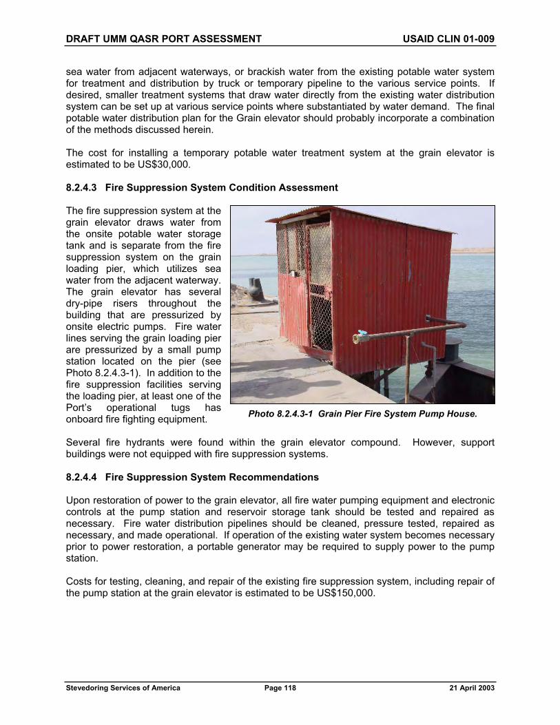
DRAFT UMM QASR PORT ASSESSMENT USAID CLIN 01-009
Stevedoring Services of America Page 118 21 April 2003
sea water from adjacent waterways, or brackish water from the existing potable water system for treatment and distribution by truck or temporary pipeline to the various service points. If desired, smaller treatment systems that draw water directly from the existing water distribution system can be set up at various service points where substantiated by water demand. The final potable water distribution plan for the Grain elevator should probably incorporate a combination of the methods discussed herein.
The cost for installing a temporary potable water treatment system at the grain elevator is estimated to be US$30,000.
8.2.4.3 Fire Suppression System Condition Assessment
The fire suppression system at the grain elevator draws water from the onsite potable water storage tank and is separate from the fire suppression system on the grain loading pier, which utilizes sea water from the adjacent waterway. The grain elevator has several dry-pipe risers throughout the building that are pressurized by onsite electric pumps. Fire water lines serving the grain loading pier are pressurized by a small pump station located on the pier (see Photo 8.2.4.3-1). In addition to the fire suppression facilities serving the loading pier, at least one of the Port’s operational tugs has onboard fire fighting equipment.
Several fire hydrants were found within the grain elevator compound. However, support buildings were not equipped with fire suppression systems.
8.2.4.4 Fire Suppression System Recommendations
Upon restoration of power to the grain elevator, all fire water pumping equipment and electronic controls at the pump station and reservoir storage tank should be tested and repaired as necessary. Fire water distribution pipelines should be cleaned, pressure tested, repaired as necessary, and made operational. If operation of the existing water system becomes necessary prior to power restoration, a portable generator may be required to supply power to the pump station.
Costs for testing, cleaning, and repair of the existing fire suppression system, including repair of the pump station at the grain elevator is estimated to be US$150,000.
Photo 8.2.4.3-1 Grain Pier Fire System Pump House.

DRAFT UMM QASR PORT ASSESSMENT USAID CLIN 01-009
Stevedoring Services of America Page 119 21 April 2003
8.3 SANITARY SEWER
8.3.1 General Condition Assessment
The sanitary sewer infrastructure within those portions of the Port that were inspected during this assessment (i.e., new port, old port, and grain elevator) was found to consist of individual septic systems serving the various support buildings and restroom facilities. Discharge from each septic tank is then either discharged to an infiltration system or tightlined directly to the nearest body of water without further treatment. Septic tanks have accessible openings for periodic cleaning and maintenance.
Many of the septic systems inspected were in poor condition and lacked maintenance. Septic tank access covers were broken or missing. Many of the tanks were full of debris. Some of the systems serving restrooms appear to have never been used, suggesting that water service to those facilities may have never been completed or is disconnected.
It is important to note that no records of the sanitary sewer system could be found during SSA’s investigation of the Port facilities. All of the information regarding the existing sewer system was obtained from SSA’s limited field reconnaissance of the Port.
8.3.2 General Recommendations
All sewer lines, septic tanks, infiltration systems, and discharge lines should be cleaned, repaired as required, and tested to ensure they are in proper working condition. Alternatively, portable toilets that are periodically pumped out and cleaned can be utilized throughout the Port until a permanent sanitary sewer masterplan is developed. The estimated cost to complete this work is US$200,000.
8.4 STORM DRAINAGE
8.4.1 General Condition Assessment
The existing storm drainage infrastructure consists of interconnected stormwater catch basins and inlets that seem to be generally in working condition. Several apparent storm system outfalls were observed under piers and along the Port’s shoreline. Testing of the storm drainage system was not possible during SSA’s analysis of Port facilities.
It is important to note that no records of the storm drainage system could be found during SSA’s investigation of the Port facilities. All of the information regarding the existing drainage system was obtained from SSA’s limited field reconnaissance of the Port.
8.4.2 General Recommendations
The storm drainage system throughout the Port should be cleaned, tested to ensure proper operation, and repaired where necessary. The estimated cost to complete this work is US$50,000.

DRAFT UMM QASR PORT ASSESSMENT USAID CLIN 01-009
Stevedoring Services of America Page 120 21 April 2003
SECTION 9.0 — SAFETY, SECURITY, AND ENVIRONMENTAL
9.1 INTRODUCTION
9.1.1 Initial Safety, Security, and Environmental Assessment Phase
This initial Safety, Security, and Environmental Assessment phase of the overall Security Inspection Process summarizes the first impressions (current status) and suggested next steps to take in order to safely and efficiently manage the immediate and future flow of USAID funded and other relief and rehabilitation materials and supplies.
9.1.2 Port Physical Boundary
In order to more clearly address the physical security and access to the Port, a determined Physical Boundary should be established with demarcation signs (such as “Iraq Government Property. No Trespassing.”) Figure 9.1 shows the Port’s current Physical Boundary. In order to ensure an adequate protective “clear zone” around the Port facilities, a suggested outer Physical Boundary defining a reasonable “Area of Interest” is included in Figure 9.2 to this section.
9.1.3 Assumptions
This assessment assumes the following.
SSA will manage the safety and security of the Port and Port activities inward of the determined Physical Boundary, and that:
The Port infrastructure (inward of the determined Physical Boundary), including buildings, machinery (fixed and mobile), cargo (including bulk storage facilities and containers), conduits (above and below ground), wharfs and quays (including the adjacent water and margin nearby and underneath), and grounds are initially swept and reasonably free of traps or other anti-personnel or anti-property destructive items.
9.1.3.1 Initiatives and Activities
The following initiatives and activities will be satisfied and functioning by coalition or other competent peacekeeping forces until such time as Iraqi resources are reasonably trained to assume these responsibilities and that SSA and cognizant authorities jointly agree that the Port is considered “permissively” safe and reasonably secure from external threat.
9.1.3.1.1 Waterside Boundary
The Port waterside boundary (including the approaches, channel and alongside the wharfs and quays) is actively patrolled to guard against destructive threats or nuisance/economic threats such as smuggling or stowaway activities.
9.1.3.1.2 Landside Boundary
The Port landside boundary (along the determined Physical Boundary) is actively patrolled (or a quick reaction force is immediately available) to guard against destructive threats or nuisance threats (such as civil unrest or protests).

N
Umm Qasr Port Assessment: Port Physical Boundary Enhancement - Figure 9.1
* Not to scale, modified to fit sheet
KHAWR
AZZUBAYR
KHAWR
AZZUBAYR
IRAQKUWAIT
IRAQKUWAIT
Area of Interest(Clear Zone)
Area of Interest(Clear Zone)
New Fence
Area of Interest(Clear Zone)
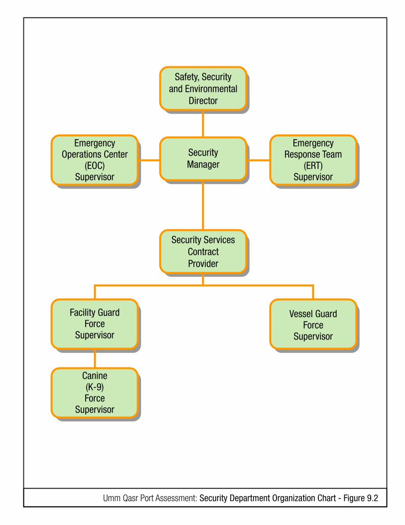
Umm Qasr Port Assessment: Security Department Organization Chart - Figure 9.2
Safety, Securityand Environmental
Director
SecurityManager
EmergencyResponse Team
(ERT)Supervisor
EmergencyOperations Center
(EOC)Supervisor
Vessel GuardForce
Supervisor
Facility GuardForce
Supervisor
Canine(K-9)Force
Supervisor
Security ServicesContractProvider

DRAFT UMM QASR PORT ASSESSMENT USAID CLIN 01-009
Stevedoring Services of America Page 123 21 April 2003
9.1.3.1.3 Security Threat Conditions
SSA will have a close liaison with the theater Embassy, coalition and other follow-on competent peacekeeping forces to share local threat and political/economic forecasts in order to plan for and to set the appropriate Anti-Terrorist (AT) /Force-Protection (FT) protective measures (mitigation strategies). SSA will have at least one employee permanently assigned at the Port with a minimum SECRET Clearance in order to facilitate the sharing of threat and political/economic forecasts.
9.2 FACILITY SAFETY, SECURITY, AND ENVIRONMENTAL ORGANIZATION
Facility Safety, Security, and Environmental best business practices are now under Coalition Forces staffing and control.
Figure 9.3 details the initially proposed Safety and Security Organization for the initial phase of SSA Port Operations management.
9.3 PROCEDURAL SECURITY
The assessment team does not consider that previous security practices and policies would be applicable. SSA will make an effort to determine what practices and policies were in place prior to the arrival of coalition forces (for background knowledge), but understands that a complete re-write of security practices and policies (based on best business practices and international standards) would be appropriate.
The basic essential practices and policies to be developed are: a Facility Security Plan including an Access Control Policy; an Emergency Response Plan; Job Descriptions and Responsibilities for the Facility Safety, Security and Environmental Department and contract Security Services Providers; and an Equipment Maintenance and Repair Policy.
9.4 PHYSICAL SECURITY
9.4.1 General
Physical Security planning and implementation is the most important first step to ensure the safety and security of an operation. Addressing the following shortfalls in Physical Security is the highest priority and essential to managing risk during any phase of Port development or operations tempo.
9.4.2 Location
The good news is that on first impressions, the Port’s overall physical security potential (based on geographic layout and natural clear zones) is quite good. With a few enhancements in physically defining the Port’s boundary (with appropriate barriers), the proposed zoning of basic areas of interest, concern and influence are more easily achieved.
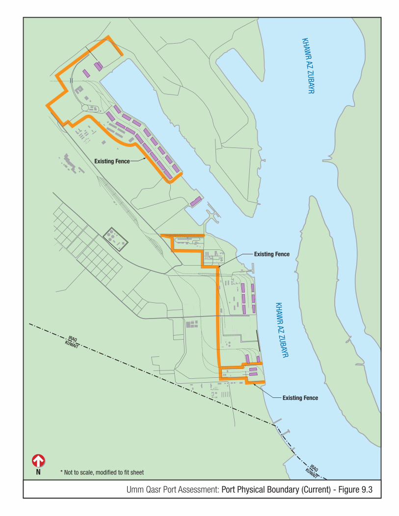
N
Umm Qasr Port Assessment: Port Physical Boundary (Current) - Figure 9.3
* Not to scale, modified to fit sheet
KHAWR
AZZUBAYR
KHAWR
AZZUBAYR
Existing Fence
Existing Fence
Existing Fence
IRAQKUWAIT
IRAQKUWAIT

DRAFT UMM QASR PORT ASSESSMENT USAID CLIN 01-009
Stevedoring Services of America Page 125 21 April 2003
9.4.3 Physical Barriers
9.4.3.1 Perimeter Walls (including fences and wire/concertina)
Both the “new” port and “old” port have a masonry wall of some variety (averaging 2.4 meters high) defining the perimeter. These perimeter walls are adequate to “define” the Zone of Concern (the area of cargo operations) but need to be more closely inspected to determine their integrity of construction. Some walls were visibly breeched (with man-sized holes or gaps) and most all of the walls either lacked the standard (30.48 centimeters or 1 foot) outrigger top with barbed or concertina wire or the wire was parted, corroded, and unserviceable. During the past several days, members of the team have witnessed young boys scaling these walls until chased away by elements of the coalition force. Figure 9.1 shows the Port’s current Physical Boundary. Figure 9.2 shows the proposed enhancements to the Port’s Physical Boundary.
Photo 9.4.3.1-1 View of Perimeter Wall with Hole.
Photo 9.4.3.1-2 View of Perimeter Wall with Holes.
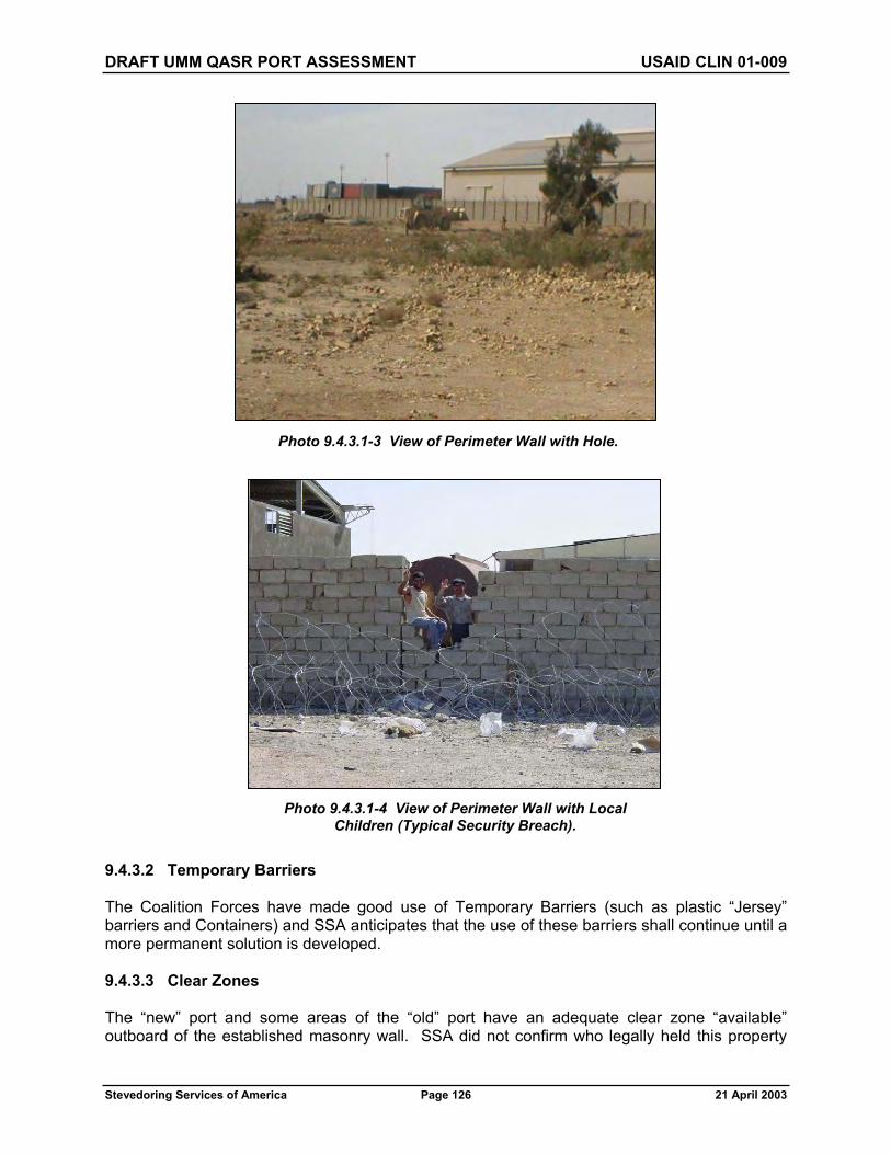
DRAFT UMM QASR PORT ASSESSMENT USAID CLIN 01-009
Stevedoring Services of America Page 126 21 April 2003
9.4.3.2 Temporary Barriers
The Coalition Forces have made good use of Temporary Barriers (such as plastic “Jersey” barriers and Containers) and SSA anticipates that the use of these barriers shall continue until a more permanent solution is developed.
9.4.3.3 Clear Zones
The “new” port and some areas of the “old” port have an adequate clear zone “available” outboard of the established masonry wall. SSA did not confirm who legally held this property
Photo 9.4.3.1-3 View of Perimeter Wall with Hole.
Photo 9.4.3.1-4 View of Perimeter Wall with Local Children (Typical Security Breach).

DRAFT UMM QASR PORT ASSESSMENT USAID CLIN 01-009
Stevedoring Services of America Page 127 21 April 2003
(land rights), but encourage that the property rights are investigated with the intent, if possible, to maintain this area clear and in the ownership (or at least easement jurisdiction) of the Port. The thought here is to ensure that an adequate exterior clear zone is maintained around the Port (as proposed in Figure 9.2) for safety and security reasons, as well as to block the development of squatters or “nuisance” commerce (Food Kiosks, Novelty Item (Tourist) Sales, etc.) that naturally follows, in close proximity, in the wake of a successful enterprise.
9.4.3.4 Locking Systems
Building and warehouse door and locking systems need to be evaluated for integrity. Some locking systems were destroyed by the forcible entry of Coalition Forces during the initial conflict activities in securing the Port. All locking systems need to be programmed to a Master Key Plan (with controlled inventory and distribution) in order to ensure the proper protection of personnel and resources.
9.4.3.5 Safes and Vaults
The team did not find any safes or vaults in this initial, brief inspection. SSA anticipates that safes, vaults, and strong-rooms will be required during the operations of the Port. These safes and vaults will need to be protected under the Master Key Plan.
9.4.3.6 Protective Lighting
There seems to be an adequate arrangement (positioning) of stadium or high-mast lights (in multiple clusters) around the Port. There also appeared to be adequate lighting fixtures attached to the warehouses along the wharfs and quays. The master power grid has not been connected yet at the port so it could not determined if any of these lights work. In addition, the team could not conduct a lighting survey at night. SSA anticipates that portable light carts will be required, at least initially, dedicated to conducting cargo operations at night (as applicable) and to the protection of personnel and high value property.
9.5 SECURITY DETECTION AND ALARM SYSTEMS
No obvious Detection and Alarm Systems were found in this initial assessment. SSA anticipates that these items will need to be included in the overall Safety and Security enhancements to the Port.
Photo 9.4.3.6-1 View of High-Mast Lighting.

DRAFT UMM QASR PORT ASSESSMENT USAID CLIN 01-009
Stevedoring Services of America Page 128 21 April 2003
9.6 SECURITY MONITORING SYSTEMS
No obvious Gate Monitoring Systems (such as CCTV) were found in this initial assessment. SSA anticipates that these items will need to be included in the overall Safety and Security enhancements to the Port.
9.7 SECURITY IDENTIFICATION SYSTEMS
The 17th Port and Maritime Regiment, Labor Services Support Unit, and Royal Logistics Corps has developed a sound system of Employee Identification Badges, with employee photos digitally captured in a data base. SSA anticipates that this system will need to be expanded (to include personnel proximity or smart cards and passes as well as a vehicle decal and pass system) and included in the overall Safety and Security enhancements to the Port.
9.8 ELECTRONIC ACCESS CONTROL SYSTEMS
No obvious Electronic Access Control Systems (such as proximity card readers and electronic door strikes) were found in this initial assessment. SSA anticipates that these items will need to be included in the overall Safety and Security enhancements to the Port.
9.9 INFORMATION SECURITY
Information (Operations) Security awareness will need to be developed and the liberal use of shredders and locked files will need to be included in the overall Safety and Security enhancements to the Port.
9.10 CLASSIFIED STORAGE
The assessment team did not observe or discover a secure system (such as a safe, strong room or vault) for the proper local (select) or bulk storage of sensitive documents. SSA will assume that previous classified storage management practices and policies will not be applicable, and that a system to classify documents by sensitivity (i.e., cargo movement schedules and human resources, accounting and payroll data) will need to be developed and that a secure system of local (select) and bulk storage of classified materials (including the safeguarding of combinations and keys) will be required.
9.11 COMMUNICATIONS SECURITY
Communications resources and Communications Security Awareness will need to be developed and will need to be included in the overall Safety and Security enhancements to the Port.
9.12 TENANT CUSTOMER AND CONTRACTOR SECURITY CONSIDERATIONS
There were no “Tenant” activities (other than Coalition Forces and their embedded contractors) to consider in this initial assessment, but Tenant Customer (such as freight forwarders, customs house brokers, and labor contractors) as well as government agency, non-government agency, and contractor security will need to be considered and included in the overall Safety and Security enhancements to the Port.

DRAFT UMM QASR PORT ASSESSMENT USAID CLIN 01-009
Stevedoring Services of America Page 129 21 April 2003
9.13 CARGO SECURITY
Cargo Security (owned and third party) is presently under the control of the Coalition Forces. Follow-on Cargo Security will need to be included in the overall Safety and Security enhancements to the Port.
9.14 PERSONNEL SECURITY
Force Protection is presently under the control of the Coalition Forces. Follow-on Security will need to be included in the overall Safety and Security enhancements to the Port.
9.15 PERSONNEL RELIABILITY (AND “VETTING”) PROGRAM
The 17th Port and Maritime Regiment, Labor Services Support Unit, Royal Logistics Corps, and the Intelligence Unit has developed a sound system “vetting” prospective employees. SSA anticipates that this system will need to be expanded (to include pre-hire background investigations as well as follow-on interval investigations and lifestyle surveys) and included in the overall Safety and Security enhancements to the Port.
9.16 SECURITY GUARD FORCES
In order to support the above Safety and Security considerations, SSA will need to contract a Security Services Provider. The Security Services Provider will be under the supervision of the Port’s Security Director. The objective is to train and equip local Iraqi citizens to fully assume this responsibility. The process of training and equipping by the Security Services Provider is an essential first step in preparing the Port to operate in the long term with indigenous resources.
9.17 CANINE (K-9) PROGRAM
A limited Canine (K-9) program (with weapons detection and resource [personnel and property] protection capabilities) is suggested and will be developed, as necessary, in the overall Safety and Security enhancements to the Port. The Canine (K-9) Program will ultimately be managed by the Security Services Provider.
9.18 HARBOR SURVEILLANCE AND WATERSIDE SECURITY
Harbor Surveillance and Waterside Security is currently provided by Coalition Forces. This activity is an essential component of the overall Safety and Security of the Port. The Harbor Surveillance and Waterside Security Program will ultimately be managed by the Security Services Provider.

DRAFT UMM QASR PORT ASSESSMENT USAID CLIN 01-009
Stevedoring Services of America Page 130 21 April 2003
Photo 9.4.3.6-1 View of U.S. Coast Guard 110-Foot Patrol Boat.
Photo 9.4.3.6-1 View of U.S. Navy Nested Patrol Boats.

DRAFT UMM QASR PORT ASSESSMENT USAID CLIN 01-009
Stevedoring Services of America Page 131 21 April 2003
9.19 HAZARDOUS MATERIALS (HAZMAT) AND DANGEROUS GOODS (DG) HANDLING, RECORD KEEPING AND STORAGE
There was no observed system for the handling, record keeping and storage of HAZMAT and DG commodities. SSA will assume that previous HAZMAT and DG management practices and policies will not be applicable, and that a complete overhaul of their handling, record keeping, and storage systems will be required for the safe and efficient operations of the Port.
HAZMAT and DG will be addressed in two categories: Third Party Cargo and Own Use.
HAZMAT and DG Third Party Cargo will be handled, controlled, and segregated in accordance with applicable international standards for maritime transport and storage (for example the International Maritime Organization’s (IMO) International Maritime Dangerous Goods (IMDG) Code), and other best business practices.
HAZMAT and DG commodities required for “Own Use” (such as petroleum, oil, chemicals [for cleaning] and lubricants) will be handled, controlled, and segregated in accordance with applicable international standards and other best business practices. “Own Use” HAZMAT and DG chemicals are expected only in limited quantities. These best business practices include HAZMAT and DG communications, review of product Material Safety Data Sheets (MSDS), secondary spill containment and recovery, and proper housekeeping.
9.20 HAZMAT AND DG DISPOSAL
There was no observed system for the proper disposal of HAZMAT and DG commodities. SSA will assume that previous HAZMAT and DG disposal management practices and policies will not be applicable, and that an environmentally sensitive system of HAZMAT and DG commodity disposal (such as recycling and incineration where applicable) will be required.
9.21 EMERGENCY RESPONSE
SSA will develop and administer a comprehensive Emergency Response Plan (and Team) based on best business practices and international standards. This program will be included in the overall Safety and Security enhancements to the Port.
9.22 ENVIRONMENTAL SENSITIVITY
The assessment team does not consider that previous Environmental Protection practices and policies would be applicable. SSA will make an effort to determine what practices and policies were in place prior to the arrival of coalition forces (for background knowledge), but understands that a complete re-write of environmental protection practices and policies (based on best business practices and international standards) would be appropriate. SSA will develop and administer a comprehensive Environmental Protection Plan to be included in the overall Safety and Security enhancements to the Port.
9.23 SAFETY, SECURITY, AND ENVIRONMENTAL TRAINING
SSA will develop and administer a comprehensive Safety, Security, and Environmental Training Program based on best business practices and international standards. This program will be included in the overall Safety and Security enhancements to the Port.

DRAFT UMM QASR PORT ASSESSMENT USAID CLIN 01-009
Stevedoring Services of America Page 132 21 April 2003
9.24 CONCLUSIONS
9.24.1 Port Physical Boundary. The Port Physical Boundary should be clearly defined, with the strong recommendation to include the extended “Area of Interest” as proposed in Figure 9.2.
9.24.2 Assumptions. The assumptions as defined above should be considered and developed as a planning tool for the initial phase of Port Operations for humanitarian and other USAID funded cargo.
9.24.3 Facility Security Assessment. A more thorough (formal) Physical Security Inspection/Survey should be conducted in order to identify, in detail, the resources and requirements necessary to satisfy the shortfalls identified above in this initial assessment.
9.24.4 Budget. The following suggests the preliminary (and approximate) budget, by priority, to consider for the initial phase of Port Operations for USAID funded cargo and other relief and rehabilitation materials and supplies.

DRAFT UMM QASR PORT ASSESSMENT USAID CLIN 01-009
Stevedoring Services of America Page 133 21 April 2003
SECTION 10.0 — MARINE OPERATIONS
10.1 MARINE OPERATIONS DEPARTMENT
The Port will create a Marine Operations Department to manage the movement of all ship traffic within the Port’s jurisdiction. This department will establish rules and regulations that all vessels must comply with when arriving and departing the Port. All vessels will be required to notify the Port authorities of all movement requests within the Port area. The guidelines to be followed will be the previous Port authority’s rules and regulations within reason and as practical, if such can be found.
The Marine Operations Department will designate anchorage areas within the Port and maintain buoyage and other navigational aids to assist all vessel movements within the Port. This department will assign tugs to vessels requiring tug assist. The tugs and other ship assist water craft are part of the overall Port working structure.
Maintaining an adequate water depth throughout the Port will be the responsibility of the Marine Operations Department. Water depth will be monitored in all areas and maintenance dredging will be scheduled as required. Permanent dredgers that are currently assigned to the Port will need to be put in working order with trained crews and dredge master and remain in place to provide this ongoing, year-around necessity. Currently, two of the five dredges are operable, three are not. An evaluation by a qualified dredging company must be conducted on all dredger vessels on hand with recommendations and cost estimates as to their viability.
The ongoing ability to communicate with arriving or departing vessels by VHF radio must continue. Currently, the British Army’s 17th Port and Maritime Regiment, Royal Logistics Corps are performing this function. Rules for arrival and departure are established and communication frequency and channel selection are identified.
10.2 QUALIFIED MARINE PILOTS
The Marine Operations Department will maintain the list of qualified marine pilots and assign these pilots to arriving and departing vessels. Pilotage is mandatory. To date, none or few of the former pilots have come forward or been identified by the British military. Procedures for replacing, training, and certifying new pilots will be an ongoing requirement.
10.3 MILITARY AND CIVIL PORT CONTROLS, COMMUNICATIONS, AND COMMAND SYSTEMS
At the time of this assessment, the team acknowledges that this area is in transition and will most likely change over the next month(s). SSA has met with the theater Maritime Liaison Office (MARLO) (of the Commander, U.S. Naval Forces, Central Command, headquartered in Manama, Bahrain) and expect to develop a more-thorough relationship with the MARLO office and other developing local initiatives.

DRAFT UMM QASR PORT ASSESSMENT USAID CLIN 01-009
Stevedoring Services of America Page 134 21 April 2003
11.0 CONCLUSION
As of 21 April 2003, ships drawing more than 8 meters draft can not get into the “new” port basin or alongside any berth from B11 through B21 due to insufficient depth of water even at the top of the tide.
As Berths 3, 4, 5, 9, and 10 have restrictions of one type or another, the effective berth capacity of the Port at present is: B1 and B2 - Bulk; B6, B7 and B8 - Breakbulk. Due to natural scouring, these berths have maintained depths alongside varying between 8 meters and 12 meters. It should be noted that the fender system at B1 through B8 and B10 have considerable deterioration and vessels may well require fendering to avoid shipside damage.
Dredging the “new” Port basin to 11.5 meters in the channel (minimum width of 122 meters) and to 12.5 meters along the berth line length B21 through B11 should proceed immediately. Mobilization and equipment procurement should be put on a highest priority basis utilizing at least two large dredgers adequate to do the job expeditiously; i.e., in the range of 1,000 cubic meters per dredge per day. Total volume of material to be dredged to give an 11.5-meter channel through the length of the Port and 12.5 meters at all berths will be approximately 6 million cubic meters.
SSA considers this to be a practical target depth while recognizing that deep-laden ships will necessitate using the tide and can be expected to take the bottom at berth.
Cargo handling gear and equipment necessary to conduct either a bulk or breakbulk discharge operation will need to be on hand as soon as possible. Apart from MHE this includes 'soft gear' such as wires, slings and shackles, plus cages, spreaders, bridles and the usual range of dock handling gear to be found in any gear-locker. Little of this type of gear has survived in useable condition.
The existing transportation infrastructure appears to be suitable for use during initial phases (Priority 1) of Port operation. Priority 2 work includes roadway and rail system repairs at both the “old” and “new” ports.
Priority 1 utility requirements include repair, cleaning, and testing of the fire suppression and potable water service Port-wide. Because water provided by the existing potable water system is brackish, and thus doesn’t meet U.S. or World Health Organization potable water quality standards, water treatment facilities will also need to be installed at each area of the Port. Stormwater and sewer system repairs are considered to be Priority 2 improvements.
The electrical system in the “old” port area is over 40 years of age, poorly maintained, and is in need of replacement. Although the “new” port electrical system has been in place just over 20 years, it has been neglected, patched, and cannibalized to the extent that it, too, needs to be replaced in its entirety. To put it bluntly, the entire system requires replacement and the cost to do just that is included as a Priority 1 item.
At the grain elevator, replace the 33kv and 3.3kv switchgear and transformers. Replace the 3.3kv cable to the vacuators and replace all cabling and electrical equipment on the vacuators and conveyors from the wharf to the elevator. Within the elevator building, replace all lighting and controls, and the existing HVAC and telephone systems. Replace the two existing 2.5Mw generators and the paralleling switchgear.

DRAFT UMM QASR PORT ASSESSMENT USAID CLIN 01-009
Stevedoring Services of America Page 135 21 April 2003
Most berth repairs may be considered to be Priority 2 items with the exception of the shotcrete repairs required at the grain terminal, Berth 10. Because repair of Berth 10 was initiated prior to the beginning of the conflict, the structural reinforcement is now exposed to the elements and must be covered as soon as possible to prevent further degradation.
Many of the berth’s fender systems exhibit damage that ranges from minor to substantial. However, none of this damage is considered to require repair on a Priority 1 basis.
Warehouses utilized for the temporary storage of Humanitarian Aid goods will require minor repairs at a Priority 1 level.
And finally, a mutual continuity of asset and force protection will be of paramount importance during the initial transition period and immediately beyond. Every effort should be made to maintain the secure environment (both the perception and the fact) established by the coalition forces. Because the Port plays such a critical role in the replenishment and reconstruction of Iraq, it is strongly recommended that all Priority 1 designated security issues are thoroughly funded.
A summary of Priority 1 and Priority 2 items is listed in the table below.
Report Reference Priority 1 Priority 2 Estimated Cost US$ Estimated Cost US$
3.0 Dredging and Wreck Removal $54,000,000 $46,800,0004.1 Bulk Operation 4,035,000 14,290,0004.2 Break/Bulk Operation 1,050,000 7,650,0004.3 Container Operation 1,945,000 1,900,0004.6 Other Operational Factors 500,000 760,0005.0 Warehouses 65,000 95,0006.0 Support Facilities 5,298,000 80,0007.0 Transportation 0 2,150,0008.0 Utilities 20,375,000 250,0009.0 Safety, Security, & Environmental 3,297,000 292,000
ESTIMATED PROGRAM COSTS US$90,565,000 US$74,267,000
APPENDIX A Warehouse Inventory
_________________________________________________________________
Note: Completed by 354 CA BDE Assessment TeamLead by CPT St. Laurent

ASSESSMENT OF WAREHOUSE COMPLEX UMM QASR OLD PORT FACILITY
Note: Completed by 354 CA BDE Assessment Team Lead by CPT St. Laurent


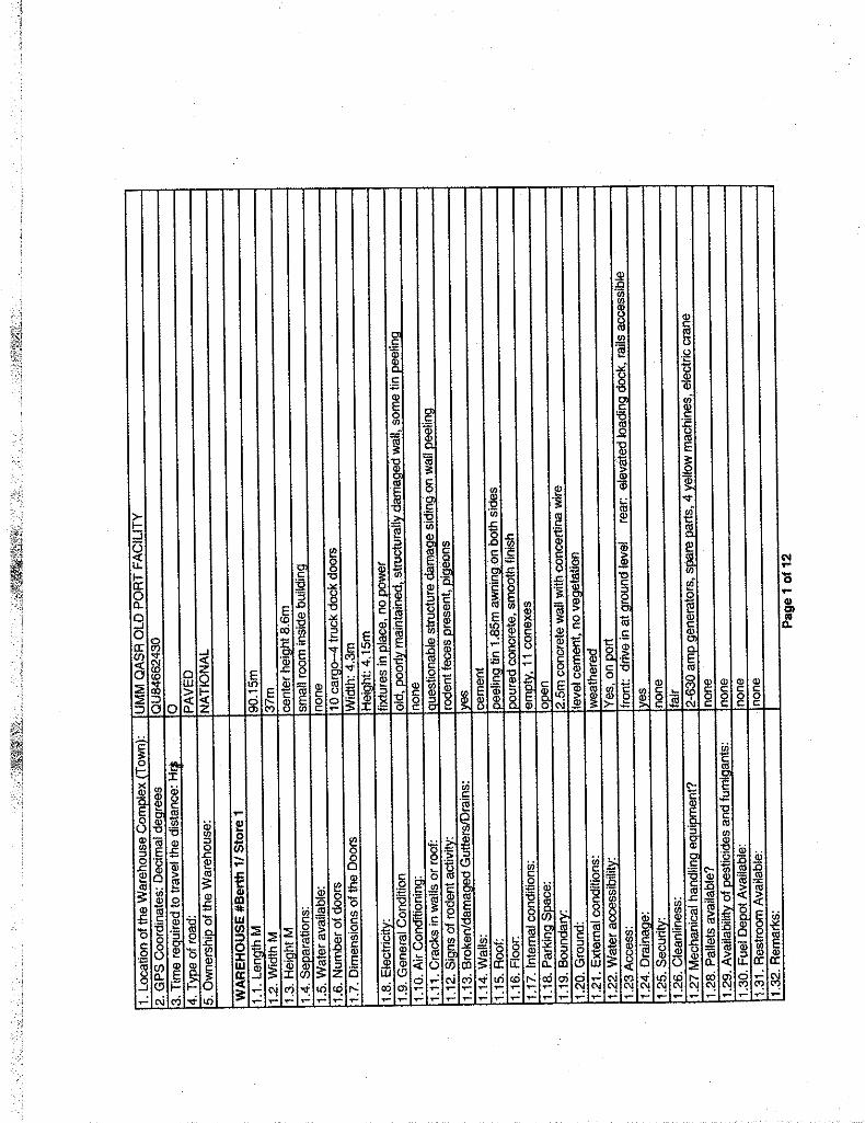

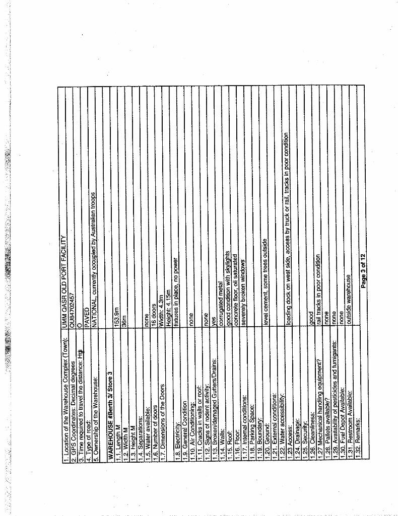


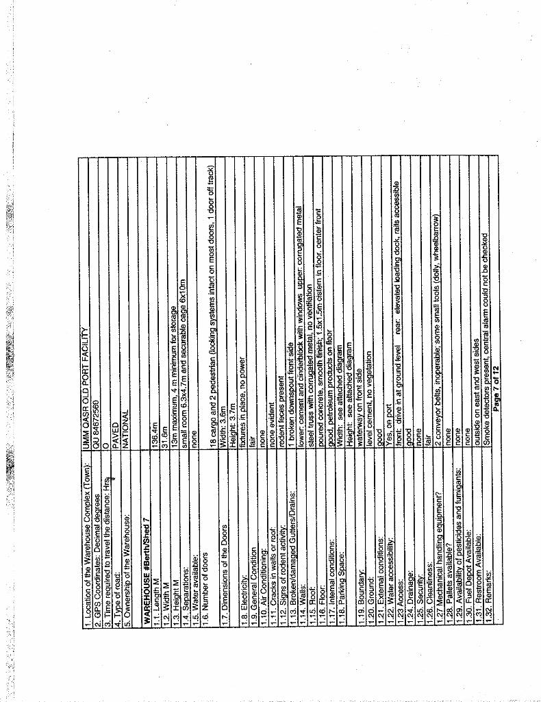


ASSESSMENT OF WAREHOUSE COMPLEX UMM QASR NEW PORT FACILITY
Note: Completed by 354 CA BDE Assessment Team Lead by CPT St. Laurent


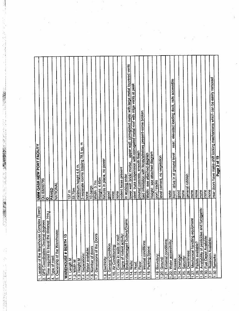

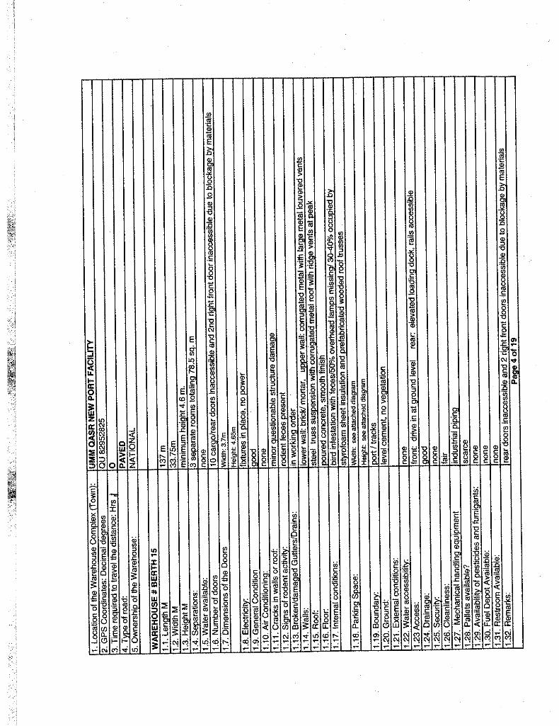

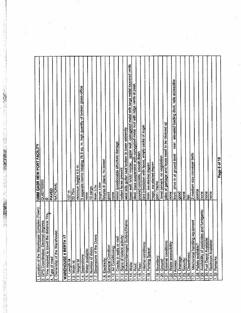


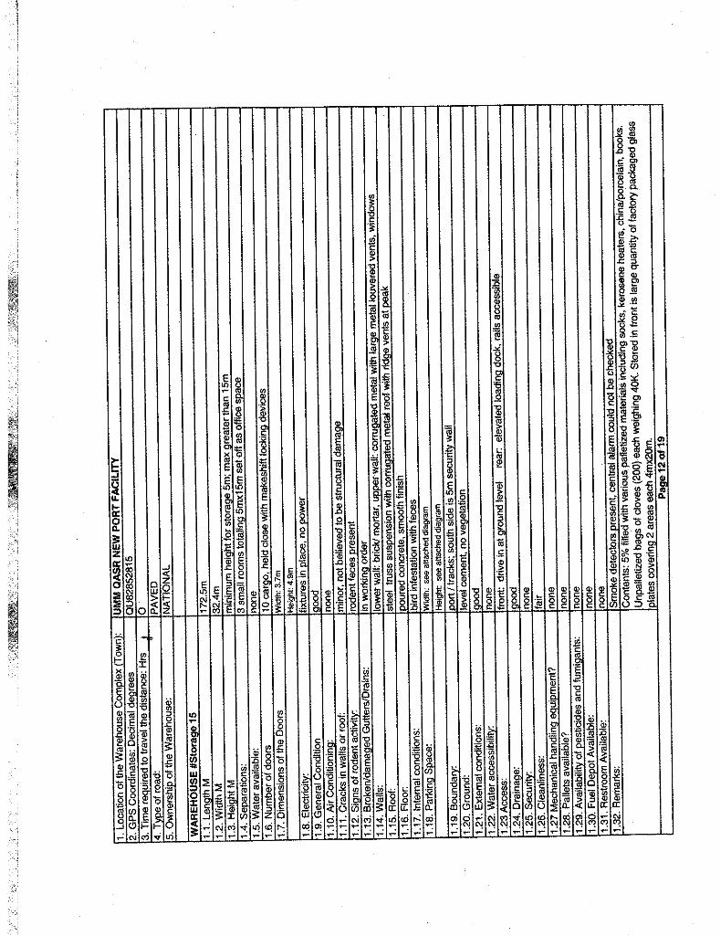

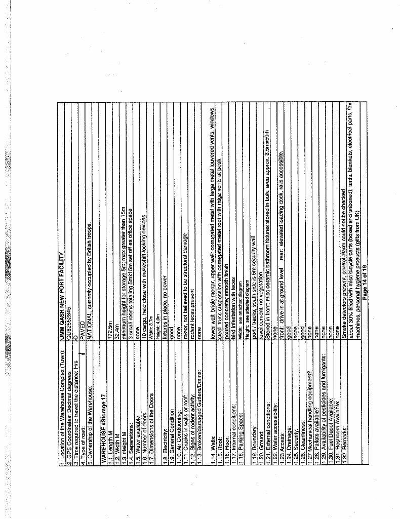

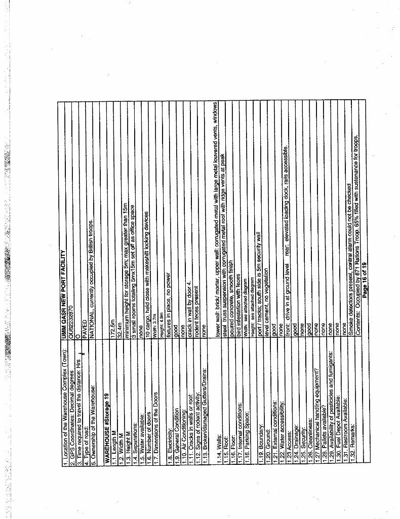
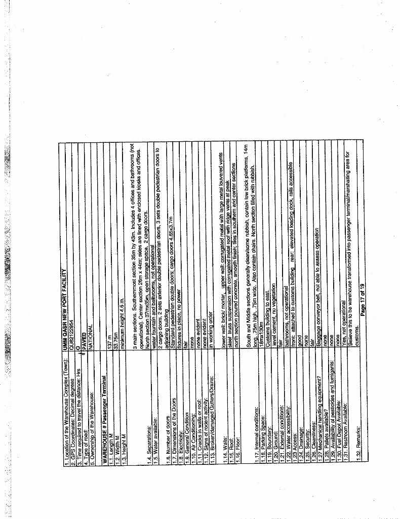


APPENDIX B Mobile Equipment Survey
______________________________________________________________
Note: The following information is furnished courtesy of the 17th Ports and Maritime Regiment, Royal Logistics Corps.

Eqpt State as @ 13 Apr 03
UMM QASR NEW PORT
Ser Eqpt Type Brand Capacity VRN UK Zap #
Approx Age
(years)
Odometer (hours)
Condition Remarks Location
(a) (b) (c) (d) (e) (f) (g) (h) (i) (j) (k) MHE:
1a (Ser # A26172)
17/3 <2 years Fit (still as new)
52 Port Sqn
1b(Ser # A26823)
17/9 <2 years Fit (OK)
Accident damage No frame
Mulberry Lines
1c
Container Handlers
Ferrari FL4212
36,000 Kg
(Ser # A26169) 17/10 <2 years Fit
(OK) Mulberry Lines
2a (Ser # 5561)
17/4 <2 years 10 Fit (still as new)
52 Port Sqn
2b(Ser # 5563)
17/30 <2 years 63 Fit (still as new)
67 Log Sqn
2c
Komatsu 15,000 Kg
(Ser # 5552) <2 years Fit
(still as new) Keys? Whereabouts?
US Lines
2d(Ser # 110045703)
17/5 <2 years 7 Fit (still as new)
52 Port Sqn
2e
Heli 10,000 Kg
(Ser # 110045712) 17/21 <2 years 15 Fit
(still as new) Mulberry Lines
2f (Ser # 11115)
17/20 <2 years 24 Fit (still as new)
Noisy Transmission
Mulberry Lines
2g(Ser # 11137)
17/19 <2 years 16 Fit (still as new)
No hydraulic filter Mulberry Lines
2h
Godrej 8000 Kg
(Ser # 11118) 17/27 <2 years 18 Fit
(OK) 67 Log Sqn
2i (Ser # D0070128)
17/2 <5 years 1128 Fit (OK)
Mulberry Lines
2l (Ser # D0070130)
17/6 <5 years 1104 Not yet assessed
Mulberry Lines
2m
Forklifts
Dalian 7000 Kg
(Ser # D0070131) <5 years 1612 Not yet
assessed Battery Building 5

Eqpt State as @ 13 Apr 03
Ser Eqpt Type Brand Capacity VRN UK Zap #
Approx Age
(years)
Odometer (hours)
Condition Remarks Location
(a) (b) (c) (d) (e) (f) (g) (h) (i) (j) (k) 2n
(Ser # D0070137) 17/7 <5 years (?) Not yet
assessed No Key Mulberry Lines
2o Komatsu 3000 Kg (Ser # 547729)
<2 years Not yet assessed
Battery Mulberry Lines
2p(Ser # 103039010)
17/29 <5 years 2168 Fit (OK)
67 Log Sqn
2q(Ser # 103039015)
17/16 <5 years 1617 Fit (OK)
Mulberry Lines
2r (Ser # 103039016)
17/15 <5 years (?) Fit (OK)
Battery Mulberry Lines
2s
Heli 3000 Kg
(Ser # 103039012) 17/26 <5 years 2090 VOR
(poor) Tyres 67 Log Sqn
2t (Ser # 30190)
17/22 <5 years 559 Fit (OK)
Mulberry Lines
2u
Godrej 3000 Kg
(Ser # 30166) 17/28 <5 years 201 Fit
(Good) 67 Log Sqn
3a MAB (Russian?)
25 Tonne 17/8 <10 year 3252 Fit (poor)
Mulberry Lines
3b
Cranes
VOLST (Russian?)
40 Tonne 17/32 <10 year Not yet assessed
No Key (Locked) Building 5
VEHICLES: 4a 17/23 <10 years Fit
(fair) DFS
4b
Fire Engine FAW
17/32 <10 years Not yet assessed
Fire Station
5 Water Bowser
Volvo 10 years+ VOR (poor)
DFS
6a 17/11 <10 years Fit (OK)
Mulberry Lines
6b
TractorUnits
MAFI
17/12 <10 years Fit (OK)
Mulberry Lines

Eqpt State as @ 13 Apr 03
Ser Eqpt Type Brand Capacity VRN UK Zap #
Approx Age
(years)
Odometer (hours)
Condition Remarks Location
(a) (b) (c) (d) (e) (f) (g) (h) (i) (j) (k) 6c 17/13 <10 years Not yet
assessed Mulberry Lines
6d <10 years Scrap Donor Vehicle Mulberry Lines
6e (Ser # RSF0257)
Fit (OK)
Mulberry Lines
6f (Ser # RSF 0307)
Fit (OK)
Mulberry Lines
6g Not yet assessed
Building 5
6h Not yet assessed
Building 5
6i
SNVI
Not yet assessed
Building 5
7a 2 years Fit (OK)
Mulberry Lines
7b
FuelTrailers
Schmitz 36,300 L
2 years Fit (OK)
Mulberry Lines
8a Not yet assessed
Mulberry Lines
8b Not yet assessed
Building 5 (Outside)
8c Not yet assessed
Building 5 (Outside)
8d Not yet assessed
Building 5 (Outside)
8e
Calabrese 4-5 Tonne
Not yet assessed
Building 5 (Outside)
8f
Trailers
SNVI 45 Tonne Flatbed
Not yet assessed
Tyres Mulberry Lines
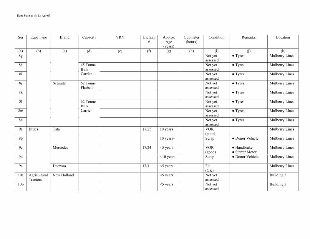
Eqpt State as @ 13 Apr 03
Ser Eqpt Type Brand Capacity VRN UK Zap #
Approx Age
(years)
Odometer (hours)
Condition Remarks Location
(a) (b) (c) (d) (e) (f) (g) (h) (i) (j) (k) 8g Not yet
assessed Tyres Mulberry Lines
8h Not yet assessed
Tyres Mulberry Lines
8i
45 Tonne Bulk Carrier Not yet
assessed Tyres Mulberry Lines
8j Not yet assessed
Tyres Mulberry Lines
8k
62 Tonne Flatbed
Not yet assessed
Tyres Mulberry Lines
8l Not yet assessed
Tyres Mulberry Lines
8m Not yet assessed
Tyres Mulberry Lines
8n
Schmitz
62 Tonne Bulk Carrier
Not yet assessed
Tyres Mulberry Lines
9a 17/25 10 years+ VOR (poor)
Mulberry Lines
9b
Tata
10 years+ Scrap Donor Vehicle Mulberry Lines
9c 17/24 <5 years VOR (good)
Handbrake Starter Motor
Mulberry Lines
9d
Mercedes
<10 years Scrap Donor Vehicle Mulberry Lines
9e
Buses
Daewoo 17/1 <5 years Fit (OK)
Mulberry Lines
10a <5 years Not yet assessed
Building 5
10b
Agricultural Tractors
New Holland
<5 years Not yet assessed
Building 5
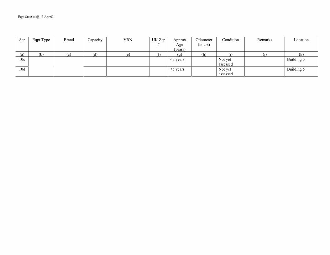
Eqpt State as @ 13 Apr 03
Ser Eqpt Type Brand Capacity VRN UK Zap #
Approx Age
(years)
Odometer (hours)
Condition Remarks Location
(a) (b) (c) (d) (e) (f) (g) (h) (i) (j) (k) 10c <5 years Not yet
assessed Building 5
10d <5 years Not yet assessed
Building 5

Eqpt State as @ 13 Apr 03
UMM QASR OLD PORT
Ser Eqpt Type Brand Capacity VRN UK Zap # Approx Age(years)
Odometer (hours)
Condition Remarks Location
(a) (b) (c) (d) (e) (f) (g) (h) (i) (j) (k) Mobile Grain Vacuators:
1. 2 years 2000+ Fit (Good)
Berth 1, Store 1
2. 2 years 2000+ VOR (Good)
Holed fuel tank Berth 1, Store 1
3. 2 years 2000+ Fit (Good)
Berth 1, Store 1
4. 2 years 2000+ Fit (Good)
Berth 1, Store 1
5. 2 years 2000+ Fit (Good)
Berth 1, Store 1
6.
Roncuzzi
2 years 2000+ Fit (Good)
Berth 1, Store 1
Straddle Container Carriers: <5 years Not yet
assessed Keys missing Quayside
<5 years Not yet assessed
Keys missing Quayside
<5 years Not yet assessed
Keys missing Quayside
Antheus 40 Tonne
<5 years Not yet assessed
Keys missing Quayside
MHE: Container
Handlers Ferrari FL4212 36,000 Kg <2 years Fit
(still as new) Berth 2, Shed 2
Forklifts Komatsu 15,000 Kg (Ser # 5551)
<2 years Not yet assessed
Australian Lines?
(Ser # 5548)
<2 years Not yet assessed
US Lines?

Eqpt State as @ 13 Apr 03
(Ser # 5550)
<2 years Not yet assessed
US Lines?
VEHICLES: Tractor Units MAFI <10 years Not yet
assessed US Lines?
Trailer Calabrese Not yet assessed
US Lines?

APPENDIX C Old Port Dockside Crane Survey
_________________________________________________________________
Note: The following information is furnished courtesy of the 17th Ports and Maritime Regiment, Royal Logistics Corps.
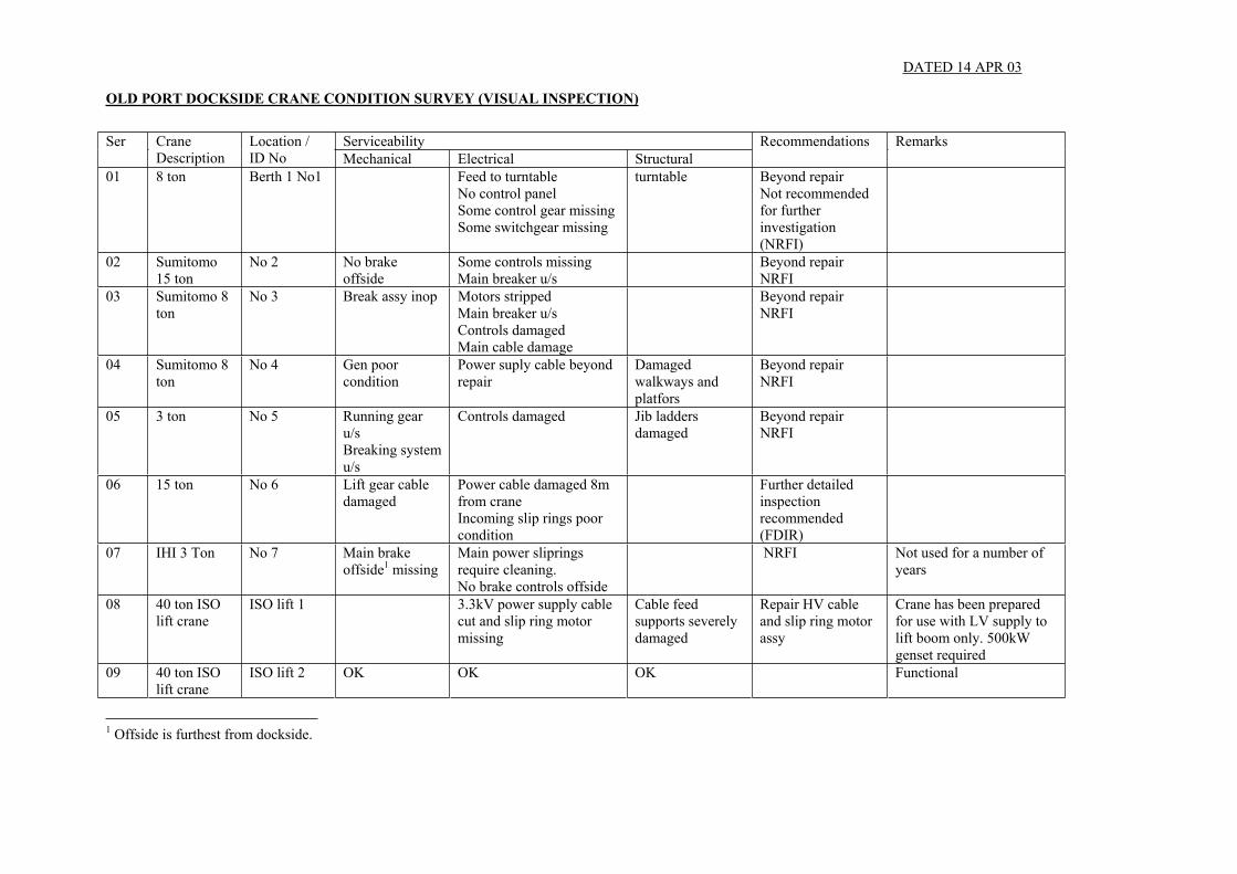
ServiceabilitySer Crane Description
Location / ID No Mechanical Electrical Structural
Recommendations Remarks
01 8 ton Berth 1 No1 Feed to turntable No control panel Some control gear missing Some switchgear missing
turntable Beyond repair Not recommended for further investigation (NRFI)
02 Sumitomo 15 ton
No 2 No brake offside
Some controls missing Main breaker u/s
Beyond repair NRFI
03 Sumitomo 8 ton
No 3 Break assy inop Motors stripped Main breaker u/s Controls damaged Main cable damage
Beyond repair NRFI
04 Sumitomo 8 ton
No 4 Gen poor condition
Power suply cable beyond repair
Damaged walkways and platfors
Beyond repair NRFI
05 3 ton No 5 Running gear u/s Breaking system u/s
Controls damaged Jib ladders damaged
Beyond repair NRFI
06 15 ton No 6 Lift gear cable damaged
Power cable damaged 8m from crane Incoming slip rings poor condition
Further detailed inspection recommended (FDIR)
07 IHI 3 Ton No 7 Main brake offside1 missing
Main power sliprings require cleaning. No brake controls offside
NRFI Not used for a number of years
08 40 ton ISO lift crane
ISO lift 1 3.3kV power supply cable cut and slip ring motor missing
Cable feed supports severely damaged
Repair HV cable and slip ring motor assy
Crane has been prepared for use with LV supply to lift boom only. 500kW genset required
09 40 ton ISO lift crane
ISO lift 2 OK OK OK Functional
1 Offside is furthest from dockside.
OLD PORT DOCKSIDE CRANE CONDITION SURVEY (VISUAL INSPECTION)
DATED 14 APR 03

10 15 ton No 8 Local no 12
OK General electrical damage FDIR
11 15 ton No 9 local No2
Hoist brake missing. Oil leak on turntable
Running gear power supply cut. Main power distribution damaged
Beyond repair NRFI
12 3 ton No 10 local No 3
Cable realer u/s Power to travel gear u/s Beyond repair NRFI
13 3 ton No 11 local No 4
Cable realer u/s Power to travel gear u/s Beyond repair NRFI
14 N/K No 12 local No 5
Large oil leak on jib gearbox
Main power distribution damaged
Beyond repair due to age NRFI
15 N/K No 13 local No 6
Extensive oil leaks
Main power distribution damaged
Beyond repair due to age NRFI
16 N/K No 14 local No 7
OK OK OK Operational with separate generator supply.Load test reqd.
Functional
17 N/K No 15 local No 8
OK Travel function inop within cab. Functional at ground level control.
OK Operational with separate generator supply.Load test reqd.
Functional
18 N/K No 16 local No 9
Turntable u/s (wheel missing)
Power cable u/s Beyond repair due to age NRFI
19 N/K No 17 local No 10
Jib oil leak Power to travel u/s Cab unsafe Poss further investigation
20 8/5t SPMP No 18 local No 11
OK OK OK Visual OK Detailed inspection ongoing
Reqd for priority assessment
2 Local numbering annotated with spray paint

21 5t SPMP No 19 local 12
OK OK OK Visual OK Detailed inspection ongoing
Reqd for priority assessment
22 15/8/5t SPMP
No 20 local 13
OK OK OK Operational with separate generator supply.Load test reqd
Functional
23 5t SPMP No 21 local 14
OK OK OK Operational with separate generator supply.Load test reqd
Functional
24 IHI 3t No 22 local 15
Travel electrical controls missing. Transformer for jib and hoist u/s Electrical components missing
Access ladder unsafe
NRFI
25 IHI 8t No 23 local 16
Various electrical components missing (mainly controls)
Access ladder damaged
MDIR
26 3t No 24 local 17
Uu/s due to age NRFI
27 8/5t SPMP No 25 local 18
OK Minor electrical housing damage
OK Good condition MDIR
28 5t No 26 local 19
OK Travel function inop within cab. Functional at ground level control
OK Operational with separate generator supply.Load test reqd
29 15/8/5t SPMP
No 27 local 20
OK OK Minor access ladder damage
Operational with separate generator supply.Load test reqd
30 5t SPMP No 28 local 21
OK Minor component damage Minor damage Good MDIR

31 5t Sumitomo No 29 local 22
Brake damage Cable realer damaged Extensive electrical components and controls missing
Hand rails damaged Superficial structure damage
NRFI
32 N/K NRFI Cranes u/s
Jibs removed
33 N/K NRFI Cranes u/s
Jibs removed
Notes
1. All cranes can be moved by towing with minimal preparation.. 2. Generally all main power cable connections at socket are in poor condition. 3. FDIR - Further detailed inspection recommended. 4. NRFI - Not recommended for further investigation. 5. All cranes annotated SPMP are of Chinese origin and are approximately 3-5 years old and generally in good condition with only minor faults 6. All low load electrical distribution and controls generally in poor condition but can and have been bypassed or disconnected to operate crane without some safety
features unless otherwise stated.