Embed Size (px)
Citation preview
* 6 0 0 2 8 7 5 1 8 *
EN
SS7012
DC SIGNAL SOURCEInstruction Manual
Mar. 2015 Revised edition 8 SS7012A981-08 15-03H
99 Washington Street Melrose, MA 02176 Phone 781-665-1400Toll Free 1-800-517-8431
Visit us at www.TestEquipmentDepot.com
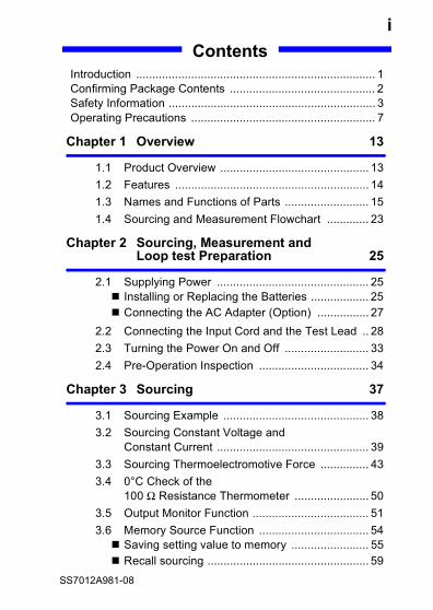
iContents
Introduction .......................................................................... 1Confirming Package Contents ............................................. 2Safety Information ................................................................ 3Operating Precautions ......................................................... 7
Chapter 1 Overview 13
1.1 Product Overview .............................................. 131.2 Features ............................................................ 141.3 Names and Functions of Parts .......................... 151.4 Sourcing and Measurement Flowchart ............. 23
Chapter 2 Sourcing, Measurement and Loop test Preparation 25
2.1 Supplying Power ............................................... 25 Installing or Replacing the Batteries .................. 25 Connecting the AC Adapter (Option) ................ 27
2.2 Connecting the Input Cord and the Test Lead .. 282.3 Turning the Power On and Off .......................... 332.4 Pre-Operation Inspection .................................. 34
Chapter 3 Sourcing 37
3.1 Sourcing Example ............................................. 383.2 Sourcing Constant Voltage and
Constant Current ............................................... 393.3 Sourcing Thermoelectromotive Force ............... 433.4 0°C Check of the
100 Ω Resistance Thermometer ....................... 503.5 Output Monitor Function .................................... 513.6 Memory Source Function .................................. 54 Saving setting value to memory ........................ 55 Recall sourcing .................................................. 59
SS7012A981-08
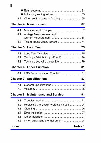
ii Scan sourcing ....................................................61 Initializing setting values ....................................63
3.7 When setting value is flashing ...........................65
Chapter 4 Measurement 67
4.1 Measurement Example ......................................674.2 Voltage Measurement and
Current Measurement ........................................684.3 Temperature Measurement ...............................71
Chapter 5 Loop Test 75
5.1 Loop Test Overview ...........................................755.2 Testing a Distributor (4-20 mA) .........................765.3 Testing a two-wire transmitter ...........................79
Chapter 6 Other Function 81
6.1 USB Communication Function ..........................81
Chapter 7 Specifications 83
7.1 General Specifications .......................................837.2 Accuracy ............................................................86
Chapter 8 Maintenance and Service 91
8.1 Troubleshooting .................................................918.2 Replacing the Circuit Protection Fuse ...............948.3 Cleaning ............................................................968.4 Error Indication ..................................................978.5 Other Indication .................................................978.6 When calibrating the instrument ........................98
Index Index 1

Introduction
1Thank you for purchasing the HIOKI Model SS7012 DC SignalSource. To obtain maximum performance from the instrument,please read this manual first, and keep it handy for future refer-ence.
Introduction
Confirming Package Contents
2When you receive the instrument, inspect it carefully to ensurethat no damage occurred during shipping. In particular, checkthe accessories, panel switches, and connectors. If damage isevident, or if it fails to operate according to the specifications,contact your dealer or Hioki representative.
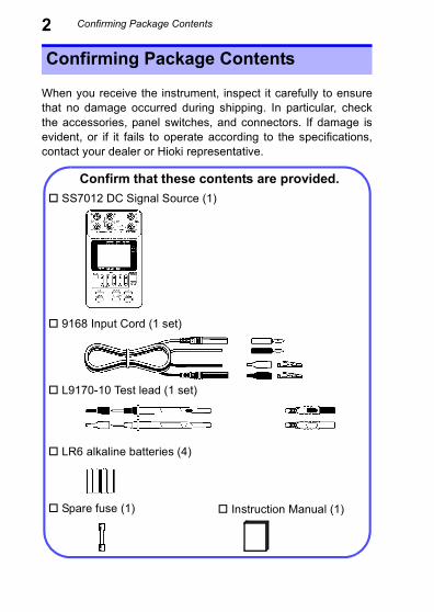
Confirming Package Contents
Confirm that these contents are provided. SS7012 DC Signal Source (1)
Instruction Manual (1)
9168 Input Cord (1 set)
LR6 alkaline batteries (4)
L9170-10 Test lead (1 set)
Spare fuse (1)
Safety Information
3Options 9184 Temperature Probe (reference junction compensation) 9380 Carrying Case (Holds main unit only, soft case) 9782 Carrying Case (Holds options, hard case) 9445-02 AC Adapter (For Japan, US, and Canada) 9445-03 AC Adapter (For EU) SS9000 Communication Package(Includes USB cable and USB driver software)
Safety Information
This instrument is designed to comply with IEC 61010Safety Standards, and has been thoroughly tested forsafety prior to shipment. However, mishandling during usecould result in injury or death, as well as damage to theinstrument. Using the instrument in a way not described inthis manual may negate the provided safety features.Be certain that you understand the instructions and pre-cautions in the manual before use. We disclaim anyresponsibility for accidents or injuries not resulting directlyfrom instrument defects.
Safety Information
4This manual contains information and warnings essential forsafe operation of the instrument and for maintaining it in safeoperating condition. Before using it, be sure to carefully read thefollowing safety precautions.The following symbols in this manual indicate the relative impor-tance of cautions and warnings.
Safety Symbols
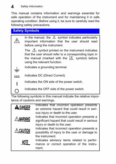
In the manual, the symbol indicates particularlyimportant information that the user should readbefore using the instrument.The symbol printed on the instrument indicatesthat the user should refer to a corresponding topic inthe manual (marked with the symbol) beforeusing the relevant function.Indicates a grounding terminal.
Indicates DC (Direct Current).
Indicates the ON side of the power switch.
Indicates the OFF side of the power switch.
Indicates that incorrect operation presentsan extreme hazard that could result in seri-ous injury or death to the user.Indicates that incorrect operation presents asignificant hazard that could result in seriousinjury or death to the user.Indicates that incorrect operation presents apossibility of injury to the user or damage tothe instrument.Indicates advisory items related to perfor-mance or correct operation of the instru-ment.
Safety Information
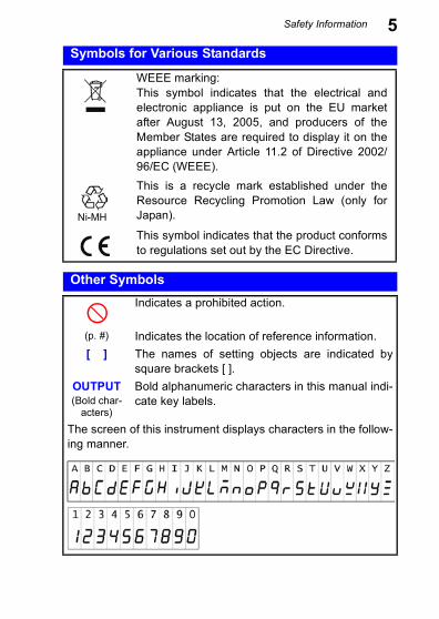
5Symbols for Various StandardsWEEE marking:This symbol indicates that the electrical andelectronic appliance is put on the EU marketafter August 13, 2005, and producers of theMember States are required to display it on theappliance under Article 11.2 of Directive 2002/96/EC (WEEE).
Ni-MH
This is a recycle mark established under theResource Recycling Promotion Law (only forJapan).
This symbol indicates that the product conformsto regulations set out by the EC Directive.
Other SymbolsIndicates a prohibited action.
(p. #) Indicates the location of reference information.[ ] The names of setting objects are indicated by
square brackets [ ].OUTPUT(Bold char-
acters)
Bold alphanumeric characters in this manual indi-cate key labels.
The screen of this instrument displays characters in the follow-ing manner.
Safety Information
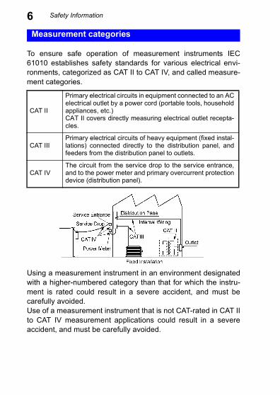
6To ensure safe operation of measurement instruments IEC61010 establishes safety standards for various electrical envi-ronments, categorized as CAT II to CAT IV, and called measure-ment categories.
Using a measurement instrument in an environment designatedwith a higher-numbered category than that for which the instru-ment is rated could result in a severe accident, and must becarefully avoided.Use of a measurement instrument that is not CAT-rated in CAT IIto CAT IV measurement applications could result in a severeaccident, and must be carefully avoided.
Measurement categories
CAT II
Primary electrical circuits in equipment connected to an ACelectrical outlet by a power cord (portable tools, householdappliances, etc.)CAT II covers directly measuring electrical outlet recepta-cles.
CAT IIIPrimary electrical circuits of heavy equipment (fixed instal-lations) connected directly to the distribution panel, andfeeders from the distribution panel to outlets.
CAT IVThe circuit from the service drop to the service entrance,and to the power meter and primary overcurrent protectiondevice (distribution panel).
Operating Precautions
7Follow these precautions to ensure safe operation and to obtainthe full benefits of the various functions.
Before using the instrument for the first time, verify that it oper-ates normally to ensure that no damage occurred during storageor shipping. If you find any damage, contact your dealer or Hiokirepresentative.
Operating temperature and humidity: 0 to 40°C at 80%RH orless (non-condensating)Temperature and humidity range for guaranteed accuracy:23±5°C, 80%RH or less (non-condensating)
Operating Precautions
Preliminary Checks
Instrument Installation
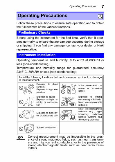
Avoid the following locations that could cause an accident or damageto the instrument.
Exposed to directsunlightExposed to high tem-perature
In the presence of cor-rosive or explosivegases
Exposed to liquidsExposed to high hu-midity or condensa-tion
Exposed to strongelectromagnetic fieldsNear electromagneticradiators
Exposed to high lev-els of particulate dust
Near electromagneticradiators (e.g., high-frequency inductionheating systems andIH cooking utensils)
Subject to vibration
Correct measurement may be impossible in the pres-ence of strong magnetic fields, such as near transform-ers and high-current conductors, or in the presence ofstrong electromagnetic fields such as near radio trans-mitters.
Operating Precautions
8Handling the InstrumentThe maximum rated voltage between input terminals andground is 30 VAC/ 60 VDC. Attempting to measure voltagesexceeding 30 VAC/ 60 VDC with respect to ground coulddamage the instrument and result in personal injury.
• This instrument is designed for safe operation only at lowvoltage. Ensure that no more than 60 V is presentbetween any terminal and ground, and that the potentialdifference between any two terminals does not exceed 60V. The instrument cannot be guaranteed in an overrangesituation, such as due to an inadvertent electric shock orfaulty insulation, and we cannot accept responsibility forany consequences that might occur from misuse.
• The output terminals and the voltage and current inputterminals (terminals for the standard resistor) are all iso-lated. Before connecting the terminals, ensure that thetarget device will not provide excessive output to, orrequire excessive input from, the terminals. The instru-ment cannot be guaranteed in an overrange situation,such as due to an inadvertent electric shock or faultyinsulation, and we cannot accept responsibility for anyconsequences that might occur from misuse.
• Ensure that the input does not exceed the maximum inputvoltage or current to avoid instrument damage, short-cir-cuiting and electric shock resulting from heat building.
• Do not allow the instrument to get wet, and do not takemeasurements with wet hands. This may cause an elec-tric shock.
• The case is not hermetically sealed for protection againstexplosion, so do not use in a flammable atmosphere.
Operating Precautions
9• When the power is turned off, do not apply voltage to the volt-age input terminals. Doing so may damage the instrument.
• To avoid damage to the instrument, protect it from physicalshock when transporting and handling. Be especially carefulto avoid physical shock from dropping.
• If this instrument has been vibrated or impacted, restart itbefore use.
• Before sourcing or measurement, make sure of the functionposition. If current or voltage in excess of sourcing or mea-surement range is input, the instrument may be damaged.
• Note that the instrument may be damaged if the applied volt-age or current exceeds the measurement range.
• If output is impossible when is displayed which indicatesoutputting, set to with OUTPUT ON/OFF key and setoutput to ON again.
• To avoid corrosion and damage to this instrument from batteryleakage, remove the batteries from the instrument if it is to bestored for a long time.
To avoid problems with battery operation, remove thebatteries from the instrument if it is to be stored for along time.
Operating Precautions
10Handling the Cords• Before using the instrument, make sure that the insula-tion on the test lead and input cord is undamaged andthat no bare conductors are improperly exposed. Usingthe instrument in such conditions could cause an electricshock, so contact your dealer or Hioki representative forrepair.
• Use the 9168 Input Cord with DC 28 V or less.If this level is exceeded, electric shock may occur.
• Always turn both devices OFF when connecting and dis-connecting an interface connector. Otherwise, an electricshock accident may occur.
• To avoid breaking the test lead and input cord, do not bend orpull them.
• For safety reasons, when taking measurements, only use theL9170-10 Test lead provided with the instrument.
Operating Precautions
11Handling the AC Adapter and the Nickel Hydride Batteries• Turn the instrument off before connecting the AC adapterto the instrument and to AC power.
• Use only the supplied Model 9445-02 AC Adapter orModel 9445-03 AC Adapter. AC adapter input voltagerange is 100 to 240 VAC (with ±10% stability) at 50/60 Hz.To avoid electrical hazards and damage to the instrument,do not apply voltage outside of this range.
• To avoid damaging the power cord, grasp the plug, not thecord, when unplugging it from the power outlet.
The nickel hydride battery is subject to self-discharge.Be sure to charge the nickel hydride batteries before ini-tial use. If the battery capacity remains very low aftercorrect recharging, the useful battery life is at an end.
1.1 Product Overview
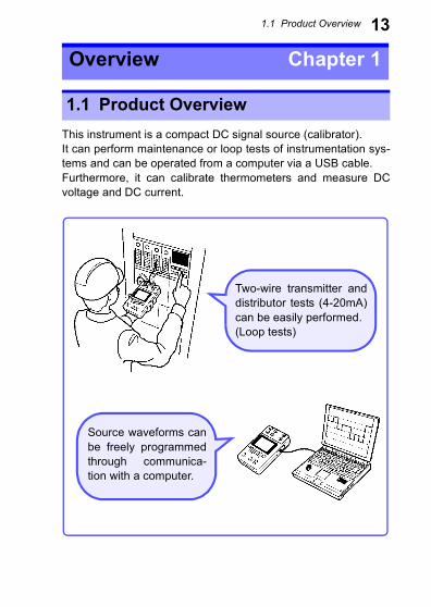
13This instrument is a compact DC signal source (calibrator).It can perform maintenance or loop tests of instrumentation sys-tems and can be operated from a computer via a USB cable.Furthermore, it can calibrate thermometers and measure DCvoltage and DC current.
Overview Chapter 1
1.1 Product Overview
Two-wire transmitter anddistributor tests (4-20mA)can be easily performed.(Loop tests)
Source waveforms canbe freely programmedthrough communica-tion with a computer.
1.2 Features
141.2 Features
Source function (p.39) (p.43)Sourcing DC voltage from -25.000 V to +25.000 V (minimumresolution 100 μV), and DC current from -25.000 mA to25.000 mA (minimum resolution 1 μA). Sourcing thermoelec-tromotive force by setting temperature (thermocouples: K, E,J, T, R, S, B, N; JIS C1602-1995, IEC 584).
Measure function (p.68) (p.71)Measurement of DC voltage from -28.000 V to +28.000 V(minimum resolution 100 μV), and of DC current from -28.000 mA to 28.000 mA (minimum resolution 1 μA). Tem-perature measurement from -25°C to 80°C with the optionalModel 9184 Temperature Probe.
Loop test (p.75)The output of this instrument is bipolar and it can sink cur-rent. Therefore, loop test in the instrumentation system ispossible.
Output monitor function (p.51)This function monitors the applied current of the constantvoltage source.This function monitors the applied voltage of the constantcurrent source.This function monitors the reference junction temperature ofthe thermoelectromotive force source.
Memory source function (p.54)Up to 20 units of source data (settings) for each function canbe saved to memory. Settings saved to memory can besourced in recall source mode or scan source mode.
AC power is not required for operationCommon LR6 alkaline batteries or nickel hydride batteriessupport use in situations where AC power is not available.
Continuous long-term operationThe optional Model 9445-02 AC Adapter or 9445-03 ACAdapter allows continuous long-term operation.
1.3 Names and Functions of Parts
151.3 Names and Functions of Parts
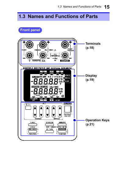
Front panel
Display(p.19)
Operation Keys(p.21)
Terminals(p.18)
1.3 Names and Functions of Parts
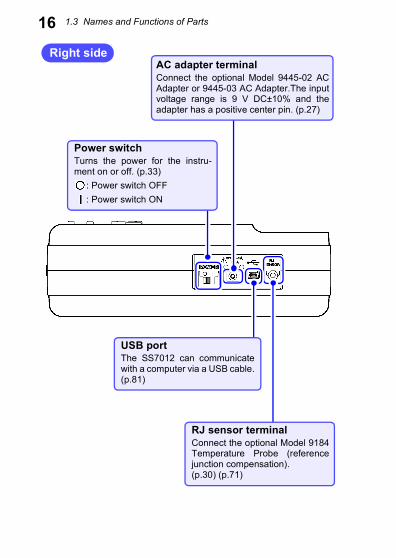
16Right side
RJ sensor terminalConnect the optional Model 9184Temperature Probe (referencejunction compensation).(p.30) (p.71)
USB portThe SS7012 can communicatewith a computer via a USB cable.(p.81)
AC adapter terminalConnect the optional Model 9445-02 ACAdapter or 9445-03 AC Adapter.The inputvoltage range is 9 V DC±10% and theadapter has a positive center pin. (p.27)
Power switchTurns the power for the instru-ment on or off. (p.33)
: Power switch OFF: Power switch ON
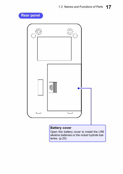
1.3 Names and Functions of Parts 17Rear panel
Battery coverOpen this battery cover to install the LR6alkaline batteries or the nickel hydride bat-teries. (p.25)
1.3 Names and Functions of Parts
18Terminals
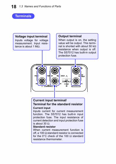
Voltage input terminalInputs voltage for voltagemeasurement. Input resis-tance is about 1 MΩ.
Current input terminal/Terminal for the standard resistorCurrent inputInputs current for current measurementfunction. The SS7012 has built-in inputprotection fuse. The input resistance ofcurrent detection and input protection fuseis about 30 Ω.Standard resistorWhen current measurement function isoff, a 100 Ω standard resistor is connectedfor the 0°C check of the 100 Ω standardresistance thermometer.
Output terminalWhen output is on, the settingvalue will be output. This termi-nal is shorted with about 50 kΩresistance when output is off.The SS7012 has built-in outputprotection fuse.
1.3 Names and Functions of Parts
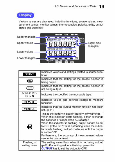
19DisplayVarious values are displayed, including functions, source values, mea-surement values, monitor values, thermocouples, polarity, units, outputstatus and warnings.
SOURCE ON OFF
MEASURE MONITOR ADJ RMT
K
V
CmA
V
CmA
E J T R S BN
Upper values
Lower values
Upper triangles
Lower triangles
Right sidetriangles
Indicates values and settings related to source func-tions.Indicates that the setting for the source function isbeing output.Indicates that the setting for the source function isnot being output.
K/ E/ J/ T/ R/ S/ B/ N Indicates the specified thermocouple type.
Indicates values and settings related to measurefunctions.Indicates that the output monitor function has beenset. (p.51)This is the battery indicator (Battery low warning).When this indicator starts flashing, either exchangethe batteries or connect the AC adapter.When this indicator is flashing, output cannot be setto ON. (If the SS7012 is outputting when the indica-tor starts flashing, output continues until the outputis set to OFF.Furthermore, the accuracy of measurement valuescannot be guaranteed.
Flashing ofsetting value
The setting value flash when it is not being output.(p.65) If a setting value is flashing, press the OUTPUT key to set the output to OFF.
1.3 Names and Functions of Parts
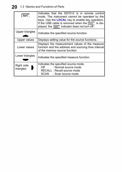
20Indicates that the SS7012 is in remote controlmode. The instrument cannot be operated by thekeys. Use the LOCAL key to enable key operation.If the USB cable is removed when the is dis-played, the indicator does not turn off.Indicates the specified source function.
Upper values Displays setting value for the source functions.
Lower valuesDisplays the measurement values of the measurefunction and the address and sourcing time intervalof the memory source function.
Indicates the specified measure function.
Indicates the specified source mode.Off : Normal source modeRECALL : Recall source modeSCAN : Scan source mode
Upper triangles
Lower triangles
Right sidetriangles
1.3 Names and Functions of Parts
21Operation Keys
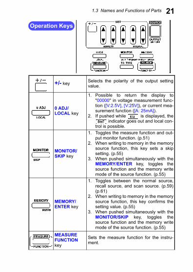
+/- key Selects the polarity of the output settingvalue.
0 ADJ/LOCAL key
1. Possible to return the display to"00000" in voltage measurement func-tion ([V:2.5V], [V:25V]), or current mea-surement function ([A: 25mA]).
2. If pushed while is displayed, the indicator goes out and local con-
trol is possible.
MONITOR/SKIP key
1. Toggles the measure function and out-put monitor function. (p.51)
2. When writing to memory in the memorysource function, this key sets a skipsetting. (p.55)
3. When pushed simultaneously with theMEMORY/ENTER key, toggles thesource function and the memory writemode of the source function. (p.55)
MEMORY/ENTER key
1. Toggles between the normal source,recall source, and scan source. (p.59)(p.61)
2. When writing to memory in the memorysource function, this key confirms thesetting value. (p.55)
3. When pushed simultaneously with theMONITOR/SKIP key, toggles thesource function and the memory writemode of the source function. (p.55)
MEASUREFUNCTIONkey
Sets the measure function for the instru-ment.
1.3 Names and Functions of Parts
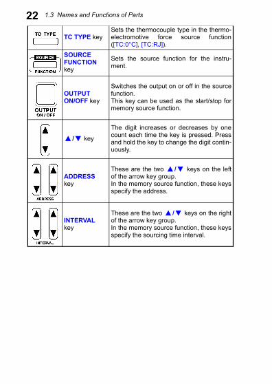
22TC TYPE keySets the thermocouple type in the thermo-electromotive force source function([TC:0°C], [TC:RJ]).
SOURCEFUNCTIONkey
Sets the source function for the instru-ment.
OUTPUTON/OFF key
Switches the output on or off in the sourcefunction.This key can be used as the start/stop formemory source function.
/ key
The digit increases or decreases by onecount each time the key is pressed. Pressand hold the key to change the digit contin-uously.
ADDRESSkey
These are the two / keys on the leftof the arrow key group.In the memory source function, these keysspecify the address.
INTERVALkey
These are the two / keys on the rightof the arrow key group.In the memory source function, these keysspecify the sourcing time interval.
1.4 Sourcing and Measurement Flowchart
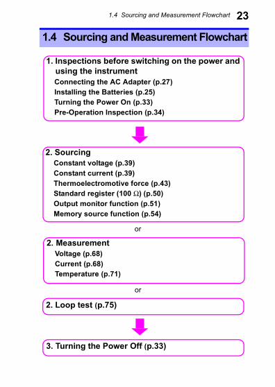
231.4 Sourcing and Measurement Flowchart
1. Inspections before switching on the power andusing the instrumentConnecting the AC Adapter (p.27)Installing the Batteries (p.25)Turning the Power On (p.33)Pre-Operation Inspection (p.34)
2. SourcingConstant voltage (p.39)Constant current (p.39)Thermoelectromotive force (p.43)Standard register (100 Ω) (p.50)Output monitor function (p.51)Memory source function (p.54)
2. MeasurementVoltage (p.68)Current (p.68)Temperature (p.71)
3. Turning the Power Off (p.33)
2. Loop test (p.75)
or
or
2.1 Supplying Power
25Sourcing, Measurementand Loop testPreparation Chapter 2
2.1 Supplying Power
Installing or Replacing the Batteries
• Use the common LR6 alkaline batteries or the commonnickel hydride batteries.
• To avoid electric shock, turn off the power switch and dis-connect the test leads or input cords from the targetdevice before replacing the batteries.
• After replacing the batteries, replace the cover beforeusing the instrument.
• Do not mix old and new batteries, or different types ofbatteries. Also, be careful to observe battery polarity dur-ing installation. Otherwise, poor performance or damagefrom battery leakage could result.
• Battery may explode if mistreated. Do not short-circuit,disassemble or dispose of in fire. Do not recharge alka-line batteries. Handle and dispose of batteries in accor-dance with local regulations.
2.1 Supplying Power
26• Do not use the LR6 alkaline batteries together with the nickelhydride batteries.
• To avoid corrosion and damage to this instrument from batteryleakage, remove the batteries from the instrument if it is to bestored for a long time.
• The indicator flashes when the remaining batterycapacity is low. In this case, the instrument's reliabilityis not guaranteed. Replace the battery immediately.
• When the nickel hydride batteries have not been usedfor a long time and are not repeat charge and dis-charge, the device may not operate normally. (Thismay also occur immediately after purchase.)
• Please use only LR6 alkaline batteries or nickelhydride (HR6) batteries. Please do not use manga-nese, oxyride batteries, etc.
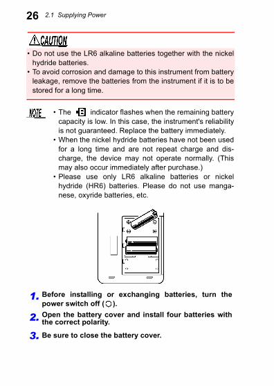
1. Before installing or exchanging batteries, turn thepower switch off ( ).
2. Open the battery cover and install four batteries withthe correct polarity.
3. Be sure to close the battery cover.
2.1 Supplying Power
27Connecting the AC Adapter (Option)• Turn the instrument off before connecting the AC adapterto the instrument and to AC power.
• Use only the supplied Model 9445-02 AC Adapter orModel 9445-03 AC Adapter. AC adapter input voltagerange is 100 to 240 VAC (with ±10% stability) at 50/60 Hz.To avoid electrical hazards and damage to the instrument,do not apply voltage outside of this range.
1. Turn the power switch off ( ).
2. Connect the 9445-02 AC Adapter or the 9445-03 ACAdapter output plug to the AC adapter terminal for theinstrument. (The input voltage range is 9 VDC±10%and the adapter has a positive center pin)
3. After making sure that the voltage of the power supplybeing used matches the supply voltage of the ACadapter, put the plug in the outlet.
2.2 Connecting the Input Cord and the Test Lead
28The SS7012 has voltage input terminal, current input terminal(terminal for the standard resistor) and output terminal.In addition, RJ sensor terminal is provided for temperature mea-surement.
Removing the sleevesGently hold the bottom of the sleeves and pull the sleeves off.Safely store the removed sleeves so as not to lose them.
Attaching the sleevesInsert the metal pins of the test leads into the holes of thesleeves, and firmly push them all the way in.
2.2 Connecting the Input Cord and the Test Lead
To prevent an electric shock accident, confirm that the white orred portion (insulation layer) inside the cable is not exposed. If acolor inside the cable is exposed, do not use the cable.
Removable sleeves are attached to the metal pins atthe ends of the test leads. The test leads can also beused with the sleeves removed.
Removing and attaching the sleeves
The tips of the metal pins are sharp, so take care not to injureyourself.
2.2 Connecting the Input Cord and the Test Lead
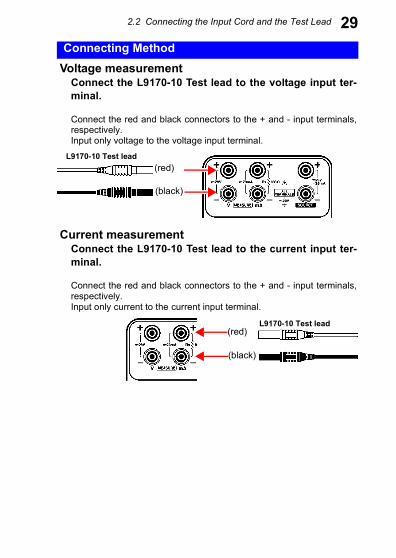
29Connecting MethodVoltage measurementConnect the L9170-10 Test lead to the voltage input ter-minal.
Connect the red and black connectors to the + and - input terminals,respectively.Input only voltage to the voltage input terminal.
L9170-10 Test lead
Current measurementConnect the L9170-10 Test lead to the current input ter-minal.
Connect the red and black connectors to the + and - input terminals,respectively.Input only current to the current input terminal.
L9170-10 Test lead
(red)
(black)
(red)
(black)
2.2 Connecting the Input Cord and the Test Lead
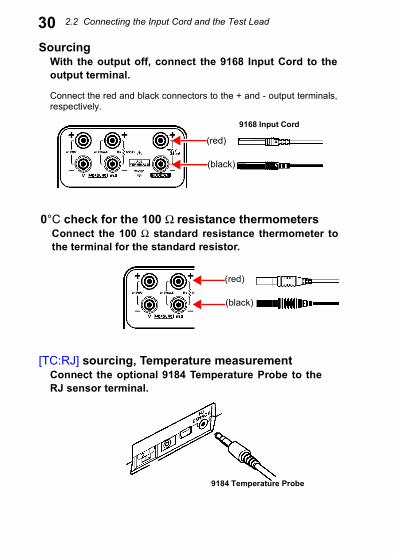
30[TC:RJ] sourcing, Temperature measurementConnect the optional 9184 Temperature Probe to theRJ sensor terminal.
9184 Temperature Probe
SourcingWith the output off, connect the 9168 Input Cord to theoutput terminal.
Connect the red and black connectors to the + and - output terminals,respectively.
9168 Input Cord
(red)
(black)
0°C check for the 100 Ω resistance thermometersConnect the 100 Ω standard resistance thermometer tothe terminal for the standard resistor.
(red)
(black)
2.2 Connecting the Input Cord and the Test Lead
31• This instrument is designed for safe operation only at lowvoltage. Ensure that no more than 60 V is presentbetween any terminal and ground, and that the potentialdifference between any two terminals does not exceed 60V. The instrument cannot be guaranteed in an overrangesituation, such as due to an inadvertent electric shock orfaulty insulation, and we cannot accept responsibility forany consequences that might occur from misuse.
• The output terminals and the voltage and current inputterminals (terminals for the standard resistor) are all iso-lated. Before connecting the terminals, ensure that thetarget device will not provide excessive output to, orrequire excessive input from, the terminals. The instru-ment cannot be guaranteed in an overrange situation,such as due to an inadvertent electric shock or faultyinsulation, and we cannot accept responsibility for anyconsequences that might occur from misuse. (For themaximum value of the output voltage/current and voltage/current input, refer to the specifications)
• To avoid electrical accidents, confirm that all connectionsare secure. The increased resistance of loose connec-tions can lead to overheating and fire.
• Be sure to connect the voltage input and current input ter-minals correctly. An incorrect connection could damageor short circuit this instrument.
2.2 Connecting the Input Cord and the Test Lead
32• When switching the power on and off, remove the targetdevice from all terminals. Furthermore, always set the outputto OFF when connecting or disconnecting the output terminaland target device. In either of these cases, failure to heed thiscaution may result in damage to the instrument or to the targetdevice.
• Do not input current more than 25 mA DC to the terminal forthe standard resistor. Doing so may damage the resistor of theinstrument.
• Output terminal and current input terminal have circuit protec-tion fuses. If the fuse is blown, output or current measurementis impossible. Exchange the fuses before operation.See: "8.2 Replacing the Circuit Protection Fuse" (p.94)
• When output is off, the output terminals are shortedwith a resistance of about 50 kΩ.
• Input resistance of the voltage input terminal isapprox. 1 MΩ and that of the current input terminal isapprox. 30 Ω.
2.3 Turning the Power On and Off
332.3 Turning the Power On and Off
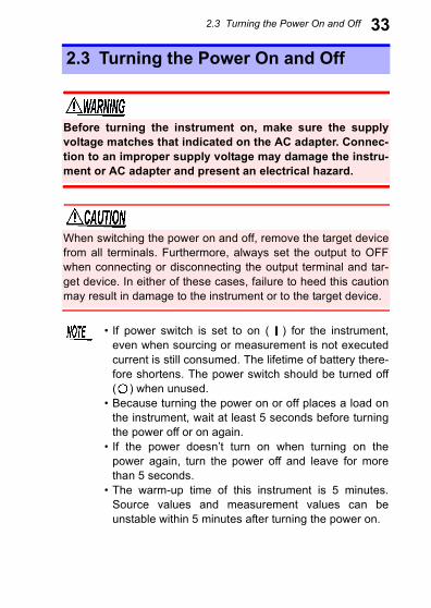
Before turning the instrument on, make sure the supplyvoltage matches that indicated on the AC adapter. Connec-tion to an improper supply voltage may damage the instru-ment or AC adapter and present an electrical hazard.
When switching the power on and off, remove the target devicefrom all terminals. Furthermore, always set the output to OFFwhen connecting or disconnecting the output terminal and tar-get device. In either of these cases, failure to heed this cautionmay result in damage to the instrument or to the target device.
• If power switch is set to on ( ) for the instrument,even when sourcing or measurement is not executedcurrent is still consumed. The lifetime of battery there-fore shortens. The power switch should be turned off( ) when unused.
• Because turning the power on or off places a load onthe instrument, wait at least 5 seconds before turningthe power off or on again.
• If the power doesn’t turn on when turning on thepower again, turn the power off and leave for morethan 5 seconds.
• The warm-up time of this instrument is 5 minutes.Source values and measurement values can beunstable within 5 minutes after turning the power on.
2.4 Pre-Operation Inspection
34Before using the instrument, verify that it operates normally toensure that no damage occurred during storage or shipping.
Turning Power On
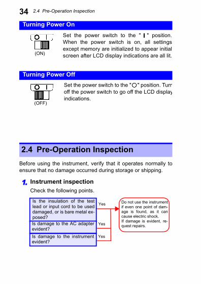
Set the power switch to the " " position.When the power switch is on, all settingsexcept memory are initialized to appear initialscreen after LCD display indications are all lit.(ON)
Turning Power Off
2.4 Pre-Operation Inspection
Set the power switch to the " " position. Turnoff the power switch to go off the LCD displayindications.
(OFF)
1. Instrument inspectionCheck the following points.
Is the insulation of the testlead or input cord to be useddamaged, or is bare metal ex-posed?Is damage to the AC adapterevident?Is damage to the instrumentevident?
Do not use the instrumentif even one point of dam-age is found, as it cancause electric shock.If damage is evident, re-quest repairs.
Yes
Yes
Yes
2.4 Pre-Operation Inspection
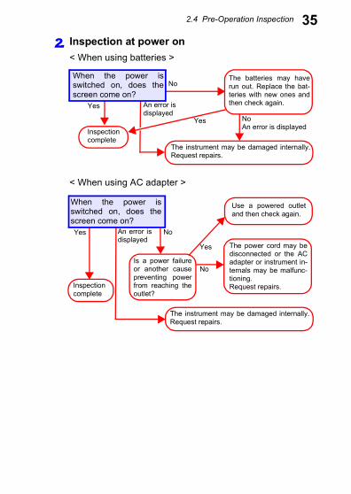
352. Inspection at power on< When using batteries >
< When using AC adapter >
The batteries may haverun out. Replace the bat-teries with new ones andthen check again.
No
Inspectioncomplete
Yes
The instrument may be damaged internally.Request repairs.
NoAn error is displayed
When the power isswitched on, does thescreen come on?
An error isdisplayed
Yes
Use a powered outletand then check again.
Yes The power cord may bedisconnected or the ACadapter or instrument in-ternals may be malfunc-tioning.Request repairs.
Is a power failureor another causepreventing powerfrom reaching theoutlet?
No
Yes
Inspectioncomplete
The instrument may be damaged internally.Request repairs.
No
When the power isswitched on, does thescreen come on?
An error isdisplayed
37
Always inspect the instrument before sourcing.See: "2.4 Pre-Operation Inspection" (p.34)
Sourcing Chapter 3
Always set the output to OFF when connecting or disconnectingthe output terminal and target device.
• If the display shows all zeros or is out of the settingrange while using the +/- keys, polarity changing isdisabled.
• Settings can be changed consecutively using the / keys. However, this operation cannot be used in
the following cases.• When the changed setting exceeds the permitted
range• When the changed setting exceeds “00000” and the
polarity changes (For example, when the setting is“00001”, all keys and the right-most key canbe used.)
3.1 Sourcing Example
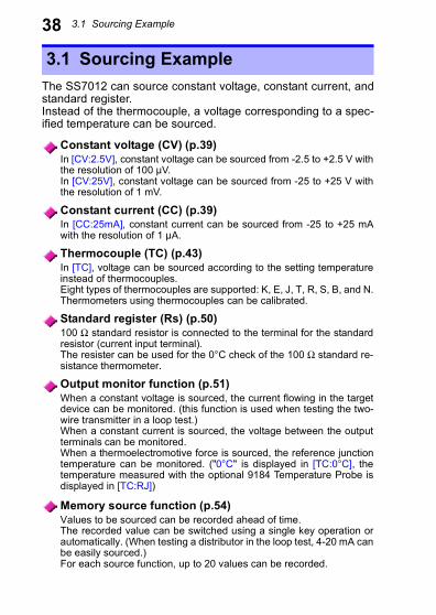
38The SS7012 can source constant voltage, constant current, andstandard register.Instead of the thermocouple, a voltage corresponding to a spec-ified temperature can be sourced.
3.1 Sourcing Example
Constant voltage (CV) (p.39)In [CV:2.5V], constant voltage can be sourced from -2.5 to +2.5 V withthe resolution of 100 µV.In [CV:25V], constant voltage can be sourced from -25 to +25 V withthe resolution of 1 mV.
Constant current (CC) (p.39)In [CC:25mA], constant current can be sourced from -25 to +25 mAwith the resolution of 1 µA.
Thermocouple (TC) (p.43)In [TC], voltage can be sourced according to the setting temperatureinstead of thermocouples.Eight types of thermocouples are supported: K, E, J, T, R, S, B, and N.Thermometers using thermocouples can be calibrated.
Standard register (Rs) (p.50)100 Ω standard resistor is connected to the terminal for the standardresistor (current input terminal).The resister can be used for the 0°C check of the 100 Ω standard re-sistance thermometer.
Output monitor function (p.51)When a constant voltage is sourced, the current flowing in the targetdevice can be monitored. (this function is used when testing the two-wire transmitter in a loop test.)When a constant current is sourced, the voltage between the outputterminals can be monitored.When a thermoelectromotive force is sourced, the reference junctiontemperature can be monitored. ("0°C" is displayed in [TC:0°C], thetemperature measured with the optional 9184 Temperature Probe isdisplayed in [TC:RJ])
Memory source function (p.54)Values to be sourced can be recorded ahead of time.The recorded value can be switched using a single key operation orautomatically. (When testing a distributor in the loop test, 4-20 mA canbe easily sourced.)For each source function, up to 20 values can be recorded.
3.2 Sourcing Constant Voltage and Constant Current
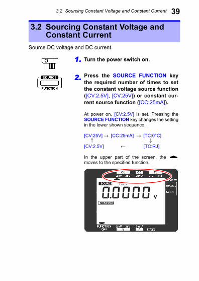
39Source DC voltage and DC current.
3.2 Sourcing Constant Voltage and Constant Current
1. Turn the power switch on.
2. Press the SOURCE FUNCTION keythe required number of times to setthe constant voltage source function([CV:2.5V], [CV:25V]) or constant cur-rent source function ([CC:25mA]).
At power on, [CV:2.5V] is set. Pressing theSOURCE FUNCTION key changes the settingin the lower shown sequence.
[CV:25V] → [CC:25mA] → [TC:0°C] ↑ ↓[CV:2.5V] ← [TC:RJ]
In the upper part of the screen, the moves to the specified function.
SOURCE ON OFF
MEASURE MONITOR ADJ RMT
K
V
CmA
V
CmA
E J T R S BN
3.2 Sourcing Constant Voltage and Constant Current
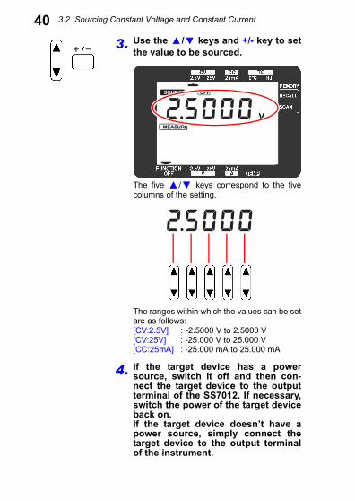
403. Use the / keys and +/- key to setthe value to be sourced.
The five / keys correspond to the fivecolumns of the setting.
The ranges within which the values can be setare as follows:[CV:2.5V] : -2.5000 V to 2.5000 V[CV:25V] : -25.000 V to 25.000 V[CC:25mA] : -25.000 mA to 25.000 mA
4. If the target device has a powersource, switch it off and then con-nect the target device to the outputterminal of the SS7012. If necessary,switch the power of the target deviceback on.If the target device doesn’t have apower source, simply connect thetarget device to the output terminalof the instrument.
SOURCE ON OFF
MEASURE MONITOR ADJ RMT
K
V
CmA
V
CmA
E J T R S BN
SOURCE ON OFF
MEASURE MONITOR ADJ RMT
K
V
CmA
V
CmA
E J T R S BN
3.2 Sourcing Constant Voltage and Constant Current
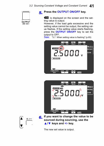
415. Press the OUTPUT ON/OFF key.is displayed on the screen and the set-ting value is output.However, if the load gets excessive and thesetting value cannot be output, the setting val-ue flashes. If the setting value starts flashing,press the OUTPUT ON/OFF key to set theoutput to OFF.See: "3.7 When setting value is flashing" (p.65)
6. If you want to change the value to besourced during sourcing, use the
/ keys and +/- key.
The new set value is output.
SOURCE ON OFF
MEASURE MONITOR ADJ RMT
K
V
CmA
V
CmA
E J T R S BN
SOURCE ON OFF
MEASURE MONITOR ADJ RMT
K
V
CmA
V
CmA
E J T R S BN
3.2 Sourcing Constant Voltage and Constant Current
427. Press the OUTPUT ON/OFF key.is displayed on the screen and the out-put changes to OFF.
Never connect this instrument to any voltage sources whensourcing constant voltage. Furthermore, never connectthis instrument to an electric current source when sourcingconstant current. Doing so may damage the instrument andthe target device.
• In constant voltage source function ([CV:2.5V], [CV:25V]), donot set the output to exceed ±25 mA. Furthermore, in constantcurrent source function ([CC:25mA]), do not set the output toexceed ±25 V. Doing so may damage the instrument and thetarget device.
• When using constant current source function, if the targetdevice is connected incorrectly, overvoltage can be applied tothe target device, which may result in damage to this instru-ment or to the target device.
If the indicator is flashing, output cannot be set toON. (If it flashes during output, output continues untiloutput is set to OFF.) Replace the batteries or connectthe AC adapter.
3.3 Sourcing Thermoelectromotive Force
43Outputs voltage according to the setting temperature instead ofthermocouples.Thermometers using thermocouples can be calibrated.There are 2 types of thermoelectromotive force source func-tions.The temperature of voltage input terminal (reference junction) ofthe thermometer can be set to either 0°C or room temperature.
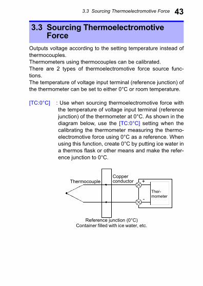
[TC:0°C] : Use when sourcing thermoelectromotive force withthe temperature of voltage input terminal (referencejunction) of the thermometer at 0°C. As shown in thediagram below, use the [TC:0°C] setting when thecalibrating the thermometer measuring the thermo-electromotive force using 0°C as a reference. Whenusing this function, create 0°C by putting ice water ina thermos flask or other means and make the refer-ence junction to 0°C.
.
3.3 Sourcing Thermoelectromotive Force
ThermocoupleCopperconductor
Reference junction (0°C)Container filled with ice water, etc.
Ther-mometer
+
-
3.3 Sourcing Thermoelectromotive Force
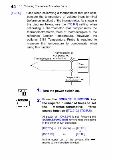
44[TC:RJ] : Use when calibrating a thermometer that can com-pensate the temperature of voltage input terminal(reference junction) of the thermometer. As shown inthe diagram below, use the [TC:RJ] setting whencalibrating a thermometer that compensates thethermoelectromotive force of thermocouples at thereference junction temperature. However, theoptional 9184 Temperature Probe is required tomeasure the temperature to compensate whenusing this function.
.
Compensationthermometer
-
Thermocouple
Thermocouple orcompensatedconductors +
Ther-mometer
1. Turn the power switch on.
2. Press the SOURCE FUNCTION keythe required number of times to setthe thermoelectromotive forcesource function ([TC:0°C], [TC:RJ]).
At power on, [CV:2.5V] is set. Pressing theSOURCE FUNCTION key changes the settingin the lower shown sequence.
[CV:25V] → [CC:25mA] → [TC:0°C] ↑ ↓[CV:2.5V] ← [TC:RJ]
In the upper part of the screen, the moves to the specified function.
3.3 Sourcing Thermoelectromotive Force
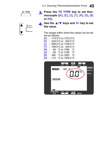
453. Press the TC TYPE key to set ther-mocouple ([K], [E], [J], [T], [R], [S], [B]or [N]).
4. Use the / keys and +/- key to setthe value.
The ranges within which the values can be setare as follows:[K] : -174.0°C to 1372.0°C[E] : -220.0°C to 839.0°C[J] : -208.0°C to 1108.0°C[T] : -169.0°C to 400.0°C[R] : -50 °C to 1768 °C[S] : -50 °C to 1768 °C[B] : 300 °C to 1820 °C[N] : -113 °C to 1300.0 °C
SOURCE ON OFF
MEASURE MONITOR ADJ RMT
K
V
CmA
V
CmA
E J T R S BN
3.3 Sourcing Thermoelectromotive Force
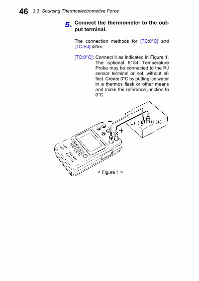
465. Connect the thermometer to the out-put terminal.
The connection methods for [TC:0°C] and[TC:RJ] differ.
[TC:0°C]: Connect it as indicated in Figure 1.The optional 9184 TemperatureProbe may be connected to the RJsensor terminal or not, without ef-fect. Create 0°C by putting ice waterin a thermos flask or other meansand make the reference junction to0°C.
< Figure 1 >
3.3 Sourcing Thermoelectromotive Force
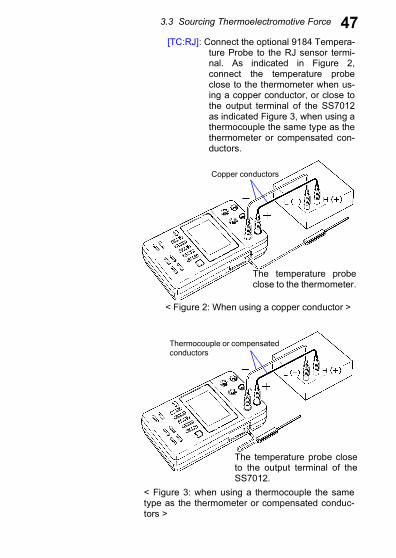
47[TC:RJ]: Connect the optional 9184 Tempera-ture Probe to the RJ sensor termi-nal. As indicated in Figure 2,connect the temperature probeclose to the thermometer when us-ing a copper conductor, or close tothe output terminal of the SS7012as indicated Figure 3, when using athermocouple the same type as thethermometer or compensated con-ductors.
< Figure 2: When using a copper conductor >
The temperature probeclose to the thermometer.
Copper conductors
< Figure 3: when using a thermocouple the sametype as the thermometer or compensated conduc-tors >
The temperature probe closeto the output terminal of theSS7012.
Thermocouple or compensatedconductors
3.3 Sourcing Thermoelectromotive Force
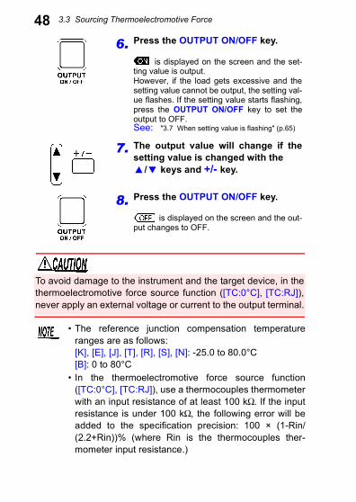
486. Press the OUTPUT ON/OFF key.is displayed on the screen and the set-ting value is output.However, if the load gets excessive and thesetting value cannot be output, the setting val-ue flashes. If the setting value starts flashing,press the OUTPUT ON/OFF key to set theoutput to OFF.See: "3.7 When setting value is flashing" (p.65)
7. The output value will change if thesetting value is changed with the
/ keys and +/- key.
8. Press the OUTPUT ON/OFF key.
is displayed on the screen and the out-put changes to OFF.
To avoid damage to the instrument and the target device, in thethermoelectromotive force source function ([TC:0°C], [TC:RJ]),never apply an external voltage or current to the output terminal.
• The reference junction compensation temperatureranges are as follows:[K], [E], [J], [T], [R], [S], [N]: -25.0 to 80.0°C [B]: 0 to 80°C
• In the thermoelectromotive force source function([TC:0°C], [TC:RJ]), use a thermocouples thermometerwith an input resistance of at least 100 kΩ. If the inputresistance is under 100 kΩ, the following error will beadded to the specification precision: 100 × (1-Rin/(2.2+Rin))% (where Rin is the thermocouples ther-mometer input resistance.)
3.3 Sourcing Thermoelectromotive Force
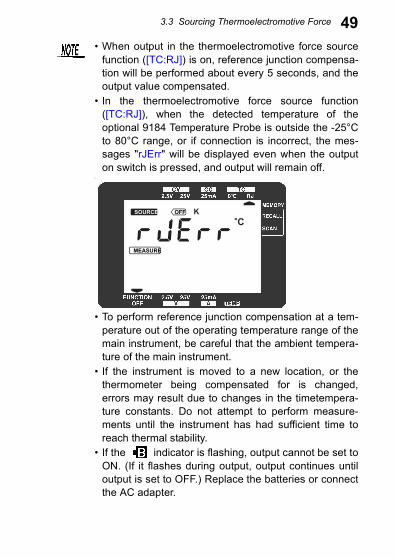
49• When output in the thermoelectromotive force sourcefunction ([TC:RJ]) is on, reference junction compensa-tion will be performed about every 5 seconds, and theoutput value compensated.
• In the thermoelectromotive force source function([TC:RJ]), when the detected temperature of theoptional 9184 Temperature Probe is outside the -25°Cto 80°C range, or if connection is incorrect, the mes-sages "rJErr" will be displayed even when the outputon switch is pressed, and output will remain off.
•
• To perform reference junction compensation at a tem-perature out of the operating temperature range of themain instrument, be careful that the ambient tempera-ture of the main instrument.
• If the instrument is moved to a new location, or thethermometer being compensated for is changed,errors may result due to changes in the timetempera-ture constants. Do not attempt to perform measure-ments until the instrument has had sufficient time toreach thermal stability.
• If the indicator is flashing, output cannot be set toON. (If it flashes during output, output continues untiloutput is set to OFF.) Replace the batteries or connectthe AC adapter.
SOURCE ON OFF
MEASURE MONITOR ADJ RMT
K
V
CmA
V
CmA
E J T R S BN
3.4 0°C Check of the 100 Ω Resistance Thermometer
50100 Ω reference resistor is connected between reference resis-tor terminals, which are the same terminals as the current inputterminals. This resistor is for 0°C check of the 100 Ω standardresistance thermometer. Usable except for current measurementfunction ([A:25mA]). Make sure measurement function is neverset to current measurement function before connecting theinstrument to the 100 Ω standard resistance thermometer.
3.4 0°C Check of the 100 Ω Resistance Thermometer
Do not input current more than 25 mA DC to the terminal for thestandard resistor. Doing so may damage the resistor of theinstrument.
3.5 Output Monitor Function
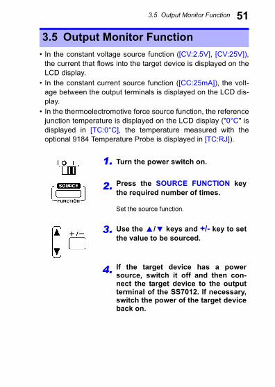
51• In the constant voltage source function ([CV:2.5V], [CV:25V]),the current that flows into the target device is displayed on theLCD display.
• In the constant current source function ([CC:25mA]), the volt-age between the output terminals is displayed on the LCD dis-play.
• In the thermoelectromotive force source function, the referencejunction temperature is displayed on the LCD display ("0°C" isdisplayed in [TC:0°C], the temperature measured with theoptional 9184 Temperature Probe is displayed in [TC:RJ]).
3.5 Output Monitor Function
1. Turn the power switch on.
2. Press the SOURCE FUNCTION keythe required number of times.
Set the source function.
3. Use the / keys and +/- key to setthe value to be sourced.
4. If the target device has a powersource, switch it off and then con-nect the target device to the outputterminal of the SS7012. If necessary,switch the power of the target deviceback on.
3.5 Output Monitor Function
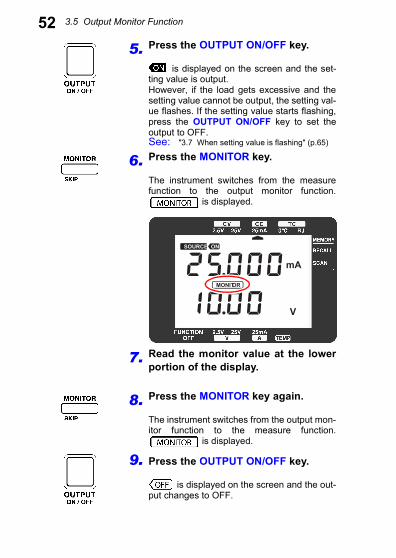
525. Press the OUTPUT ON/OFF key.is displayed on the screen and the set-ting value is output.However, if the load gets excessive and thesetting value cannot be output, the setting val-ue flashes. If the setting value starts flashing,press the OUTPUT ON/OFF key to set theoutput to OFF.See: "3.7 When setting value is flashing" (p.65)
6. Press the MONITOR key.
The instrument switches from the measurefunction to the output monitor function.
is displayed.
7. Read the monitor value at the lowerportion of the display.
8. Press the MONITOR key again.
The instrument switches from the output mon-itor function to the measure function.
is displayed.
9. Press the OUTPUT ON/OFF key.
is displayed on the screen and the out-put changes to OFF.
SOURCE ON OFF
MEASURE MONITOR ADJ RMT
K
V
CmA
V
CmA
E J T R S BN
3.5 Output Monitor Function
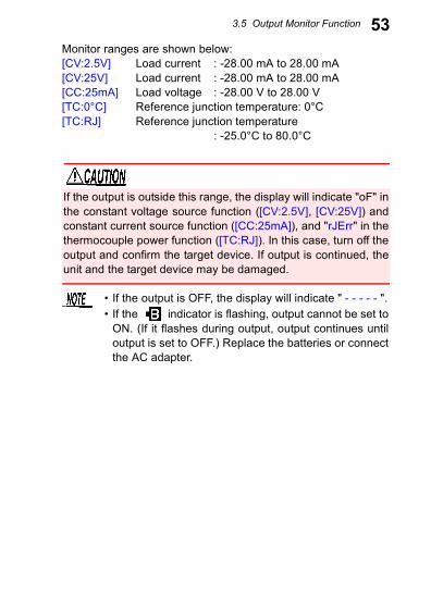
53Monitor ranges are shown below:[CV:2.5V] Load current : -28.00 mA to 28.00 mA[CV:25V] Load current : -28.00 mA to 28.00 mA[CC:25mA] Load voltage : -28.00 V to 28.00 V[TC:0°C] Reference junction temperature: 0°C[TC:RJ] Reference junction temperature: -25.0°C to 80.0°C
If the output is outside this range, the display will indicate "oF" inthe constant voltage source function ([CV:2.5V], [CV:25V]) andconstant current source function ([CC:25mA]), and "rJErr" in thethermocouple power function ([TC:RJ]). In this case, turn off theoutput and confirm the target device. If output is continued, theunit and the target device may be damaged.
• If the output is OFF, the display will indicate " - - - - - ".• If the indicator is flashing, output cannot be set to
ON. (If it flashes during output, output continues untiloutput is set to OFF.) Replace the batteries or connectthe AC adapter.
3.6 Memory Source Function
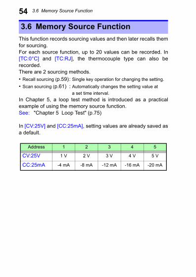
54This function records sourcing values and then later recalls themfor sourcing.For each source function, up to 20 values can be recorded. In[TC:0°C] and [TC:RJ], the thermocouple type can also berecorded.There are 2 sourcing methods.• Recall sourcing (p.59): Single key operation for changing the setting.• Scan sourcing (p.61) : Automatically changes the setting value at
a set time interval.In Chapter 5, a loop test method is introduced as a practicalexample of using the memory source function.See: "Chapter 5 Loop Test" (p.75)
In [CV:25V] and [CC:25mA], setting values are already saved asa default.
3.6 Memory Source Function
Address 1 2 3 4 5
CV:25V 1 V 2 V 3 V 4 V 5 V
CC:25mA -4 mA -8 mA -12 mA -16 mA -20 mA

3.6 Memory Source Function
55Saving setting value to memory1. Turn the power switch on.
2. Press the SOURCE FUNCTION key toset the source function.
3. Press the MONITOR key and theMEMORY key together.
The system will shift to the memory writemode."01" is displayed in the memory address andoutput setting value of the address is dis-played. At this time, if the address "01" hasbeen skipped before, "- - - - -" is displayed andnumerical value is not displayed.
Confirm that a does not appear near [MEMORY] atthe upper right of the screen (normal source mode). If a is displayed, press the MEMORY key therequired number of times until it is no longer displayed.
SOURCE ON OFF
MEASURE MONITOR ADJ RMT
K
V
CmA
V
CmA
E J T R S BN
3.6 Memory Source Function
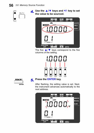
564. Use the / keys and +/- key to setthe value to be sourced.
The five / keys correspond to the fivecolumns of the setting.
5. Press the ENTER key.
After flashing, the setting value is set. Next,the instrument advances automatically to thenext address.
SOURCE ON OFF
MEASURE MONITOR ADJ RMT
K
V
CmA
V
CmA
E J T R S BN
MEASURE MONITOR ADJ RMT
V
CmA
V
CmA
SOURCE ON OFF
MEASURE MONITOR ADJ RMT
K
V
CmA
V
CmA
E J T R S BN
3.6 Memory Source Function
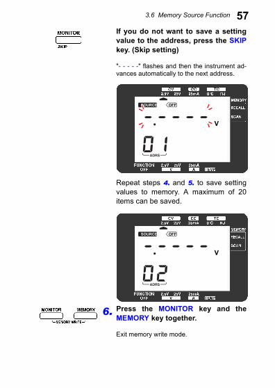
57If you do not want to save a settingvalue to the address, press the SKIPkey. (Skip setting)"- - - - -" flashes and then the instrument ad-vances automatically to the next address.
Repeat steps 4. and 5. to save settingvalues to memory. A maximum of 20items can be saved.
6. Press the MONITOR key and theMEMORY key together.
Exit memory write mode.
SOURCE ON OFF
MEASURE MONITOR ADJ RMT
K
V
CmA
V
CmA
E J T R S BN
SOURCE ON OFF
MEASURE MONITOR ADJ RMT
K
V
CmA
V
CmA
E J T R S BN
3.6 Memory Source Function
58Never switch off the power in memory write mode. It may dam-age the SS7012.
• Addresses with skip settings cannot be called by thememory source function.
• If the setting value or "- - - - -" is flashing, the settingvalue or skip setting is being written to memory.
• The sourcing time interval is set using scan sourcemode ([SCAN]).
• In memory write mode, measurements and outputmonitoring cannot be performed.
• Memory data is shared in the thermoelectromotiveforce source functions ([TC:0°C], [TC:RJ]).
3.6 Memory Source Function
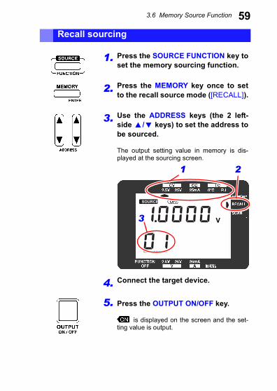
59Recall sourcing1. Press the SOURCE FUNCTION key toset the memory sourcing function.
2. Press the MEMORY key once to setto the recall source mode ([RECALL]).
3. Use the ADDRESS keys (the 2 left-side / keys) to set the address tobe sourced.
The output setting value in memory is dis-played at the sourcing screen.
4. Connect the target device.
5. Press the OUTPUT ON/OFF key.
is displayed on the screen and the set-ting value is output.
SOURCE ON OFF
MEASURE MONITOR ADJ RMT
K
V
CmA
V
CmA
E J T R S BN
1 2
3
3.6 Memory Source Function
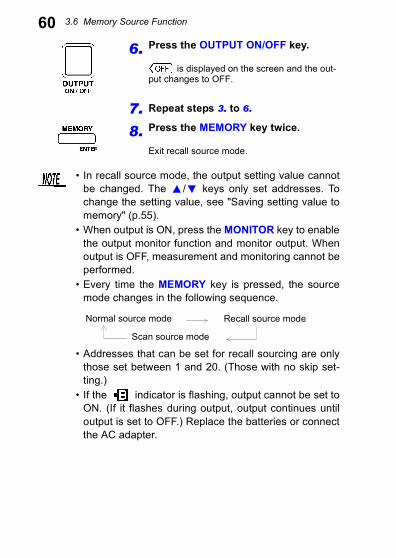
606. Press the OUTPUT ON/OFF key.is displayed on the screen and the out-put changes to OFF.
7. Repeat steps 3. to 6.
8. Press the MEMORY key twice.
Exit recall source mode.
• In recall source mode, the output setting value cannotbe changed. The / keys only set addresses. Tochange the setting value, see "Saving setting value tomemory" (p.55).
• When output is ON, press the MONITOR key to enablethe output monitor function and monitor output. Whenoutput is OFF, measurement and monitoring cannot beperformed.
• Every time the MEMORY key is pressed, the sourcemode changes in the following sequence.
• Addresses that can be set for recall sourcing are onlythose set between 1 and 20. (Those with no skip set-ting.)
• If the indicator is flashing, output cannot be set toON. (If it flashes during output, output continues untiloutput is set to OFF.) Replace the batteries or connectthe AC adapter.
Normal source mode Recall source mode
Scan source mode
3.6 Memory Source Function
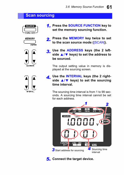
61Scan sourcing1. Press the SOURCE FUNCTION key toset the memory sourcing function.
2. Press the MEMORY key twice to setto the scan source mode ([SCAN]).
3. Use the ADDRESS keys (the 2 left-side / keys) to set the address tobe sourced.
The output setting value in memory is dis-played at the sourcing screen.
4. Use the INTERVAL keys (the 2 right-side / keys) to set the sourcingtime interval.
The sourcing time interval is from 1 to 99 sec-onds. A sourcing time interval cannot be setfor each address.
5. Connect the target device.
SOURCE ON OFF
MEASURE MONITOR ADJ RMT
K
V
CmA
V
CmA
E J T R S BN
1 2
3 Start address for sourcing 4 Sourcing timeinterval
3.6 Memory Source Function
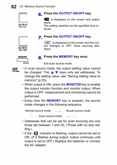
626. Press the OUTPUT ON/OFF key.is displayed on the screen and outputstarts.The setting switches by the specified time in-terval.
7. Press the OUTPUT ON/OFF key.
is displayed on the screen and the out-put changes to OFF. Scan sourcing alsostops.
8. Press the MEMORY key once.
Exit scan source mode.
• In scan source mode, the output setting value cannotbe changed. The / keys only set addresses. Tochange the setting value, see "Saving setting value tomemory" (p.55).
• When output is ON, press the MONITOR key to enablethe output monitor function and monitor output. Whenoutput is OFF, measurement and monitoring cannot beperformed.
• Every time the MEMORY key is pressed, the sourcemode changes in the following sequence.
• Addresses that can be set for scan sourcing are onlythose set between 1 and 20. (Those with no skip set-ting.)
• If the indicator is flashing, output cannot be set toON. (If it flashes during output, output continues untiloutput is set to OFF.) Replace the batteries or connectthe AC adapter.
Normal source mode Recall source mode
Scan source mode
3.6 Memory Source Function
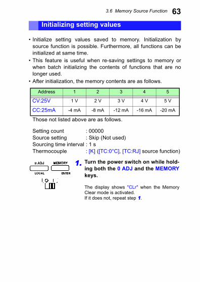
63• Initialize setting values saved to memory. Initialization bysource function is possible. Furthermore, all functions can beinitialized at same time.
• This feature is useful when re-saving settings to memory orwhen batch initializing the contents of functions that are nolonger used.
• After initialization, the memory contents are as follows.
Those not listed above are as follows.
Setting count : 00000 Source setting : Skip (Not used) Sourcing time interval : 1 sThermocouple : [K] ([TC:0°C], [TC:RJ] source function)
Initializing setting values
Address 1 2 3 4 5
CV:25V 1 V 2 V 3 V 4 V 5 V
CC:25mA -4 mA -8 mA -12 mA -16 mA -20 mA
1. Turn the power switch on while hold-ing both the 0 ADJ and the MEMORYkeys.
The display shows "CLr" when the MemoryClear mode is activated.If it does not, repeat step 1.
3.6 Memory Source Function
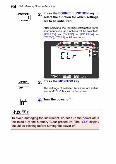
642. Press the SOURCE FUNCTION key toselect the function for which settingsare to be initialized.
After selecting the thermoelectromotive forcesource function, all functions will be selected:([CV:2.5V] → [CV:25V] → [CC:25mA] →[TC:0°C], [TC:RJ] → All functions)
3. Press the MONITOR key.
The settings of selected functions are initial-ized and “CLr” flashes on the screen.
4. Turn the power off.
SOURCE ON OFF
MEASURE MONITOR ADJ RMT
K
V
CmA
V
CmA
E J T R S BN
To avoid damaging the instrument, do not turn the power off inthe middle of the Memory Clear procedure. The "CLr" displayshould be blinking before turning the power off.
3.7 When setting value is flashing
65When the OUTPUT key is pressed and output is set to ON, set-ting value may flash.When setting value is flashing, the value being output may belower than the setting value. (Overload) Press the OUTPUT keyto set the output to OFF.Check the connection of the SS7012 and the target device. Ifthere are unexpected shorts or contact failures, eliminate them.If the setting value is still flashing even after setting output toON, the performance level of the SS7012 is being exceeded.(See below.)
In the constant voltage source function of this instrument, thepossible electrical current that can flow is ±25 mA. (Current mustflow to source the specified constant voltage.) If a currentexceeding ±25 mA flows, the source voltage may become lowerthan the setting value. In other words, the set voltage cannot besourced in this condition.Furthermore, in the constant current source function, the appliedvoltage is ±25 V. (Voltage must be applied for the specified con-stant current to flow.) If a voltage exceeding ±25 V is applied, thesource current may become lower than the setting value. Inother words, the set current cannot be sourced in this condition.
3.7 When setting value is flashing
4.1 Measurement Example
67Always inspect the instrument before measurement.See: "2.4 Pre-Operation Inspection" (p.34)
The following are the voltages, currents, and temperatures thatthe SS7012 can measure.
Measurement Chapter 4
4.1 Measurement Example
Voltage (V) (p.68)In [V:2.5V], measurement is possible from -2.8 to +2.8 V with the res-olution of 100 µV.In [V:25V], measurement is possible from -28 to +28 V with the reso-lution of 1 mV.In all cases, DC voltage can be measured.
Current (A) (p.68)In [A:25mA], measurement is possible from -28 to +28 mA with the res-olution of 1 µA.DC current can be measured.
Temperature (TEMP) (p.71)In [TEMP], measurement is possible from -25 to +80°C with the resolu-tion of 0.1°C.The optional 9184 Temperature Probe is required.
4.2 Voltage Measurement and Current Measurement
68Measure DC voltage or DC current as following procedure.
4.2 Voltage Measurement and Current Measurement
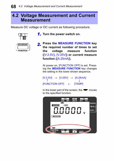
1. Turn the power switch on.
2. Press the MEASURE FUNCTION keythe required number of times to setthe voltage measure function([V:2.5V], [V:25V]) or current measurefunction ([A:25mA]).
At power on, [FUNCTION OFF] is set. Press-ing the MEASURE FUNCTION key changesthe setting in the lower shown sequence.
[V:2.5V] → [V:25V] → [A:25mA] ↑ ↓[FUNCTION OFF] ← [TEMP]
In the lower part of the screen, the movesto the specified function.
SOURCE ON OFF
MEASURE MONITOR ADJ RMT
K
V
CmA
V
CmA
E J T R S BN
4.2 Voltage Measurement and Current Measurement
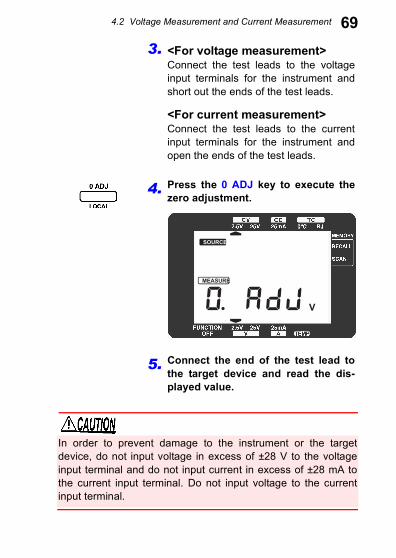
693. <For voltage measurement>Connect the test leads to the voltageinput terminals for the instrument andshort out the ends of the test leads.
<For current measurement>Connect the test leads to the currentinput terminals for the instrument andopen the ends of the test leads.
4. Press the 0 ADJ key to execute thezero adjustment.
5. Connect the end of the test lead tothe target device and read the dis-played value.
In order to prevent damage to the instrument or the targetdevice, do not input voltage in excess of ±28 V to the voltageinput terminal and do not input current in excess of ±28 mA tothe current input terminal. Do not input voltage to the currentinput terminal.
SOURCE ON OFF
MEASURE MONITOR ADJ RMT
K
V
CmA
V
CmA
E J T R S BN
4.2 Voltage Measurement and Current Measurement
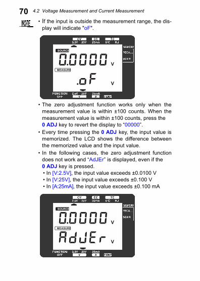
70• If the input is outside the measurement range, the dis-play will indicate "oF".
• The zero adjustment function works only when themeasurement value is within ±100 counts. When themeasurement value is within ±100 counts, press the 0 ADJ key to revert the display to “00000”.
• Every time pressing the 0 ADJ key, the input value ismemorized. The LCD shows the difference betweenthe memorized value and the input value.
• In the following cases, the zero adjustment functiondoes not work and “AdJEr” is displayed, even if the 0 ADJ key is pressed.• In [V:2.5V], the input value exceeds ±0.0100 V• In [V:25V], the input value exceeds ±0.100 V• In [A:25mA], the input value exceeds ±0.100 mA
SOURCE ON OFF
MEASURE MONITOR ADJ RMT
K
V
CmA
V
CmA
E J T R S BN
SOURCE ON OFF
MEASURE MONITOR ADJ RMT
K
V
CmA
V
CmA
E J T R S BN
4.3 Temperature Measurement
71Temperature measurement is possible with the optional 9184Temperature Probe.
4.3 Temperature Measurement
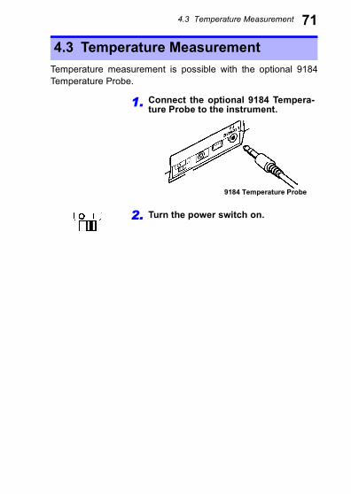
1. Connect the optional 9184 Tempera-ture Probe to the instrument.
2. Turn the power switch on.
9184 Temperature Probe
4.3 Temperature Measurement
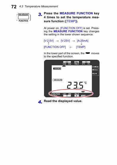
723. Press the MEASURE FUNCTION key4 times to set the temperature mea-sure function ([TEMP]).
At power on, [FUNCTION OFF] is set. Press-ing the MEASURE FUNCTION key changesthe setting in the lower shown sequence.
[V:2.5V] → [V:25V] → [A:25mA] ↑ ↓[FUNCTION OFF] ← [TEMP]
In the lower part of the screen, the movesto the specified function.
4. Read the displayed value.
SOURCE ON OFF
MEASURE MONITOR ADJ RMT
K
V
CmA
V
CmA
E J T R S BN
4.3 Temperature Measurement
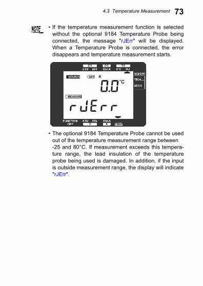
73• If the temperature measurement function is selectedwithout the optional 9184 Temperature Probe beingconnected, the message "rJErr" will be displayed.When a Temperature Probe is connected, the errordisappears and temperature measurement starts.
• The optional 9184 Temperature Probe cannot be usedout of the temperature measurement range between-25 and 80°C. If measurement exceeds this tempera-ture range, the lead insulation of the temperatureprobe being used is damaged. In addition, if the inputis outside measurement range, the display will indicate"rJErr".
SOURCE ON OFF
MEASURE MONITOR ADJ RMT
K
V
CmA
V
CmA
E J T R S BN
5.1 Loop Test Overview
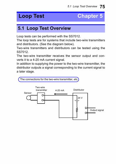
75Loop tests can be performed with the SS7012.The loop tests are for systems that include two-wire transmittersand distributors. (See the diagram below).Two-wire transmitters and distributors can be tested using theSS7012.The two-wire transmitter receives the sensor output and con-verts it to a 4-20 mA current signal.In addition to supplying the power to the two-wire transmitter, thedistributor outputs a signal corresponding to the current signal toa later stage.
Loop Test Chapter 5
5.1 Loop Test Overview
The connections for the two-wire transmitter, etc.
Sensor
Two-wire transmitter Distributor
Output signal
4-20 mA
24 V
5.2 Testing a Distributor (4-20 mA)
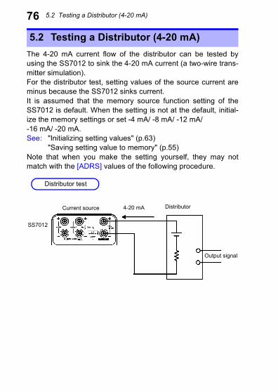
76The 4-20 mA current flow of the distributor can be tested byusing the SS7012 to sink the 4-20 mA current (a two-wire trans-mitter simulation).For the distributor test, setting values of the source current areminus because the SS7012 sinks current.It is assumed that the memory source function setting of theSS7012 is default. When the setting is not at the default, initial-ize the memory settings or set -4 mA/ -8 mA/ -12 mA/ -16 mA/ -20 mA.See: "Initializing setting values" (p.63)
"Saving setting value to memory" (p.55)Note that when you make the setting yourself, they may notmatch with the [ADRS] values of the following procedure.
5.2 Testing a Distributor (4-20 mA)
Distributor test
Current source
SS7012
Distributor4-20 mA
Output signal

5.2 Testing a Distributor (4-20 mA)
771. Check which distributor input terminal has the higher potential.
2. Checking the memory source function setting
Test procedure
1. Power on the SS7012 and perform the pre-operationinspection.See: "2.4 Pre-Operation Inspection" (p.34)
2. Press the MEASURE FUNCTION key to set the mea-sure function to [V:25V].
3. Connect the voltage input terminal of the SS7012 andthe input terminal of the instrumentation.
4. Read the voltage of the distributor input terminalsand check which terminal has the higher potential.
5. Release the connection with the distributor of theSS7012.
1. Press the SOURCE FUNCTION key to set the sourcefunction to [CC:25mA].
2. Press the MEMORY key to switch from normal sourceto recall source. (The selected memory source func-tion is displayed at the upper right display area.)
3. Check that [ADRS] is “01” and the setting is -4.000mA.
4. Press the right ADDRESS key (the ADDRESS keysare the 2 / keys on the left) and switch [ADRS]from “01” to “02”.
5. Check that the setting is -8.000 mA.
6. Press the ADDRESS key. Check that, as [ADRS]increases from “03” to “04” to “05”, the settingchanges to -12.000 mA to -16.000 mA to -20.000 mA.
7. Press the ADDRESS key to set [ADRS] to “01”.
5.2 Testing a Distributor (4-20 mA)
783. Connect the SS7012 and the distributor and then test.1. Connect the output terminal of the SS7012 and theinput terminal of the distributor as shown in the fig-ure. Be careful of the connection direction. Connectthe positive side of the output terminal of the SS7012with the input terminal of the distributor with thehigher potential. Connect the negative side of theoutput terminal of the SS7012 with the input terminalof the distributor with the lower potential.
2. Press the OUTPUT ON/OFF key to set the output toON. (During output, is displayed in the displayarea.) A current of 4.000 mA is now flowing. (The set-ting is -4.000 mA.)
3. Check the indicated value of the meter.
4. In this state, press the ADDRESS key to set [ADRS] to“02”. A current of 8.000 mA is now flowing. (The set-ting is -8.000 mA.)
5. Check the indicated value of the meter.
6. Similarly to below, increase [ADRS] to “03”, “04”, and“05". (The current flow increases to 12.000 mA,16.000 mA, and 20.000 mA). Check that the indicatedvalue of the meter accordingly.
7. Press the OUTPUT ON/OFF key to set the output toOFF.
8. Release the connection with the distributor of theSS7012.
9. Turn off the power of the SS7012.
5.3 Testing a two-wire transmitter
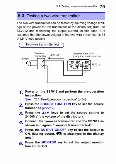
79The two-wire transmitter can be tested by sourcing voltage (volt-age of the power for the transmitter of the distributor) from theSS7012 and monitoring the output current. In this case, it isassumed that the power voltage of the two-wire transmitter is 24V. (24 V loop power)
5.3 Testing a two-wire transmitter
1. Power on the SS7012 and perform the pre-operationinspection.See: "2.4 Pre-Operation Inspection" (p.34)
2. Press the SOURCE FUNCTION key to set the sourcefunction to [CV:25V].
3. Press the / keys to set the source setting to24.000 V (the voltage of the distributor).
4. Connect the two-wire transmitter and the SS7012 asshown in diagram “Two-wire transmitter test”.
5. Press the OUTPUT ON/OFF key to set the output toON. (During output, is displayed in the displayarea.)
6. Press the MONITOR key to set the output monitorfunction to ON.
Two-wire transmitter test
4-20 mA Voltage source 24 V(Using the monitor function)
SS7012
Sensor
Two-wire transmitter
5.3 Testing a two-wire transmitter
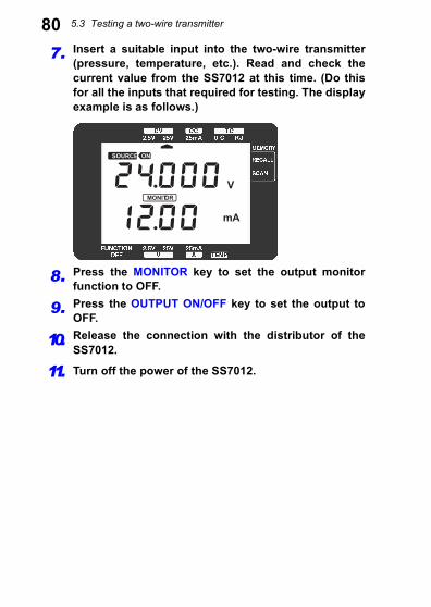
807. Insert a suitable input into the two-wire transmitter(pressure, temperature, etc.). Read and check thecurrent value from the SS7012 at this time. (Do thisfor all the inputs that required for testing. The displayexample is as follows.)
8. Press the MONITOR key to set the output monitorfunction to OFF.
9. Press the OUTPUT ON/OFF key to set the output toOFF.
10. Release the connection with the distributor of theSS7012.
11. Turn off the power of the SS7012.
SOURCE ON OFF
MEASURE MONITOR ADJ RMT
K
V
CmA
V
CmA
E J T R S BN
6.1 USB Communication Function
81The SS7012 can communicate with a computer. (Remote con-trol)The communication function can set the SS7012, as well asrecord and save settings and measurements on the computer.
Other Function Chapter 6
6.1 USB Communication Function
To use this function, the optional SS9000 Communica-tion Package is required.For more details about using the communication func-tion, see the Remote operation manual included withthe SS9000 Communication Package.
7.1 General Specifications
83Specifications Chapter 7
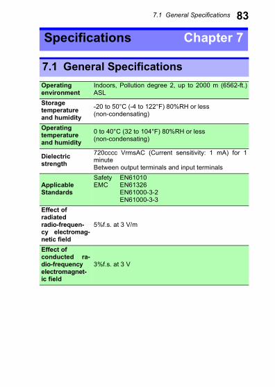
7.1 General SpecificationsOperatingenvironment
Indoors, Pollution degree 2, up to 2000 m (6562-ft.)ASL
Storagetemperatureand humidity
-20 to 50°C (-4 to 122°F) 80%RH or less(non-condensating)
Operatingtemperatureand humidity
0 to 40°C (32 to 104°F) 80%RH or less(non-condensating)
Dielectricstrength
720cccc VrmsAC (Current sensitivity: 1 mA) for 1minuteBetween output terminals and input terminals
ApplicableStandards
Safety EN61010EMC EN61326
EN61000-3-2EN61000-3-3
Effect ofradiatedradio-frequen-cy electromag-netic field
5%f.s. at 3 V/m
Effect ofconducted ra-dio-frequencyelectromagnet-ic field
3%f.s. at 3 V
7.1 General Specifications
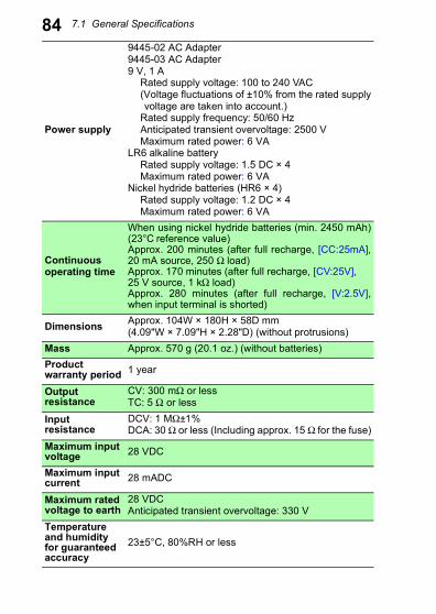
84Power supply
9445-02 AC Adapter9445-03 AC Adapter9 V, 1 A
Rated supply voltage: 100 to 240 VAC(Voltage fluctuations of ±10% from the rated supplyvoltage are taken into account.)
Rated supply frequency: 50/60 HzAnticipated transient overvoltage: 2500 VMaximum rated power: 6 VA
LR6 alkaline batteryRated supply voltage: 1.5 DC × 4Maximum rated power: 6 VA
Nickel hydride batteries (HR6 × 4)Rated supply voltage: 1.2 DC × 4Maximum rated power: 6 VA
Continuousoperating time
When using nickel hydride batteries (min. 2450 mAh)(23°C reference value)Approx. 200 minutes (after full recharge, [CC:25mA],20 mA source, 250 Ω load)Approx. 170 minutes (after full recharge, [CV:25V], 25 V source, 1 kΩ load)Approx. 280 minutes (after full recharge, [V:2.5V],when input terminal is shorted)
Dimensions Approx. 104W × 180H × 58D mm(4.09"W × 7.09"H × 2.28"D) (without protrusions)
Mass Approx. 570 g (20.1 oz.) (without batteries)Product warranty period 1 year
Outputresistance
CV: 300 mΩ or lessTC: 5 Ω or less
Inputresistance
DCV: 1 MΩ±1%DCA: 30 Ω or less (Including approx. 15 Ω for the fuse)
Maximum inputvoltage 28 VDC
Maximum inputcurrent 28 mADC
Maximum ratedvoltage to earth
28 VDCAnticipated transient overvoltage: 330 V
Temperatureand humidityfor guaranteedaccuracy
23±5°C, 80%RH or less
7.1 General Specifications
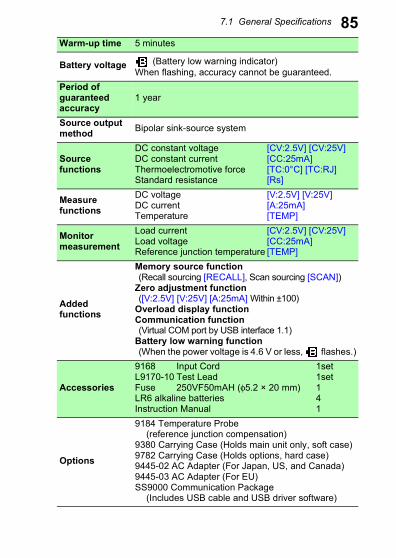
85Warm-up time 5 minutesBattery voltage (Battery low warning indicator)When flashing, accuracy cannot be guaranteed.
Period ofguaranteedaccuracy
1 year
Source outputmethod Bipolar sink-source system
Sourcefunctions
DC constant voltage [CV:2.5V] [CV:25V]DC constant current [CC:25mA]Thermoelectromotive force [TC:0°C] [TC:RJ]Standard resistance [Rs]
Measurefunctions
DC voltage [V:2.5V] [V:25V]DC current [A:25mA]Temperature [TEMP]
Monitormeasurement
Load current [CV:2.5V] [CV:25V]Load voltage [CC:25mA]Reference junction temperature [TEMP]
Addedfunctions
Memory source function(Recall sourcing [RECALL], Scan sourcing [SCAN])
Zero adjustment function([V:2.5V] [V:25V] [A:25mA] Within ±100)
Overload display functionCommunication function(Virtual COM port by USB interface 1.1)
Battery low warning function(When the power voltage is 4.6 V or less, flashes.)
Accessories
9168 Input Cord 1setL9170-10 Test Lead 1setFuse 250VF50mAH (φ5.2 × 20 mm) 1LR6 alkaline batteries 4Instruction Manual 1
Options
9184 Temperature Probe(reference junction compensation)
9380 Carrying Case (Holds main unit only, soft case)9782 Carrying Case (Holds options, hard case)9445-02 AC Adapter (For Japan, US, and Canada)9445-03 AC Adapter (For EU)SS9000 Communication Package
(Includes USB cable and USB driver software)
7.2 Accuracy
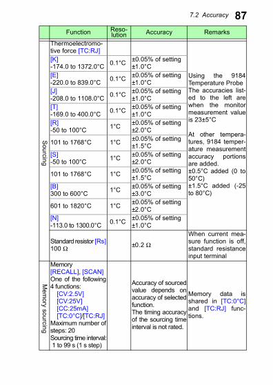
86Sourcing
7.2 Accuracy
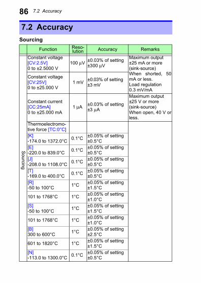
Function Reso-lution Accuracy Remarks
Constant voltage[CV:2.5V]0 to ±2.5000 V
100 μV ±0.03% of setting±300 μV
Maximum output±25 mA or more(sink-source)When shorted, 50mA or less.Load regulation 0.3 mV/mA
Constant voltage[CV:25V]0 to ±25.000 V
1 mV ±0.03% of setting±3 mV
Constant current[CC:25mA]0 to ±25.000 mA
1 μA ±0.03% of setting±3 μA
Maximum output±25 V or more(sink-source)When open, 40 V orless.
Thermoelectromo-tive force [TC:0°C][K]-174.0 to 1372.0°C 0.1°C ±0.05% of setting
±0.5°C[E]-220.0 to 839.0°C 0.1°C ±0.05% of setting
±0.5°C[J]-208.0 to 1108.0°C 0.1°C ±0.05% of setting
±0.5°C[T]-169.0 to 400.0°C 0.1°C ±0.05% of setting
±0.5°C[R]-50 to 100°C 1°C ±0.05% of setting
±1.5°C
101 to 1768°C 1°C ±0.05% of setting±1.0°C
[S]-50 to 100°C 1°C ±0.05% of setting
±1.5°C
101 to 1768°C 1°C ±0.05% of setting±1.0°C
[B]300 to 600°C 1°C ±0.05% of setting
±2.5°C
601 to 1820°C 1°C ±0.05% of setting±1.5°C
[N]-113.0 to 1300.0°C 0.1°C ±0.05% of setting
±0.5°C
Sourcing
7.2 Accuracy
87Thermoelectromo-tive force [TC:RJ]
Using the 9184Temperature ProbeThe accuracies list-ed to the left arewhen the monitormeasurement valueis 23±5°C
At other tempera-tures, 9184 temper-ature measurementaccuracy portionsare added.±0.5°C added (0 to50°C)±1.5°C added (-25to 80°C)
[K]-174.0 to 1372.0°C 0.1°C ±0.05% of setting
±1.0°C[E]-220.0 to 839.0°C 0.1°C ±0.05% of setting
±1.0°C[J]-208.0 to 1108.0°C 0.1°C ±0.05% of setting
±1.0°C[T]-169.0 to 400.0°C 0.1°C ±0.05% of setting
±1.0°C[R]-50 to 100°C 1°C ±0.05% of setting
±2.0°C
101 to 1768°C 1°C ±0.05% of setting±1.5°C
[S]-50 to 100°C 1°C ±0.05% of setting
±2.0°C
101 to 1768°C 1°C ±0.05% of setting±1.5°C
[B]300 to 600°C 1°C ±0.05% of setting
±3.0°C
601 to 1820°C 1°C ±0.05% of setting±2.0°C
[N]-113.0 to 1300.0°C 0.1°C ±0.05% of setting
±1.0°C
Standard resistor [Rs]100 Ω ±0.2 Ω
When current mea-sure function is off,standard resistanceinput terminal
Memory[RECALL], [SCAN]One of the following4 functions: [CV:2.5V] [CV:25V] [CC:25mA] [TC:0°C]/[TC:RJ]Maximum number ofsteps: 20Sourcing time interval: 1 to 99 s (1 s step)
Accuracy of sourcedvalue depends onaccuracy of selectedfunction.The timing accuracyof the sourcing timeinterval is not rated.
Memory data isshared in [TC:0°C]and [TC:RJ] func-tions.
Function Reso-lution Accuracy Remarks
Sourcing
Mem
ory sourcing
7.2 Accuracy
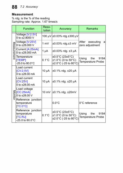
88Measurement% rdg. is the % of the readingSampling rate: Approx. 1.67 times/sFunction Reso-lution Accuracy Remarks
Voltage [V:2.5V]0 to ±2.8000 V 100 μV ±0.03% rdg.±300 μV
After executing azero adjustment
Voltage [V:25V]0 to ±28.000 V 1 mV ±0.03% rdg.±3 mV
Current [A:25mA]0 to ±28.000 mA 1 μA ±0.03% rdg. ±3 μA
Temperature[TEMP]-25.0 to 80.0°C
0.1°C±0.5°C (23±5°C)±1.0°C (0 to 50°C)±2.0°C (-25 to 80°C)
Using the 9184Temperature Probe
Load current[CV:2.5V]0 to ±28.00 mA
10 μA ±0.1% rdg. ±20 μA
Load current[CV:25V]0 to ±28.00 mA
10 μA ±0.1% rdg. ±20 μA
Load voltage[CC:25mA]0 to ±28.00 V
10 mV ±0.1% rdg. ±20mV
Reference junctiontemperature[TC:0°C]
0.0°C 0°C reference
Reference junctiontemperature[TC:RJ]-25.0 to 80.0°C
0.1°C±0.5°C (23±5°C)±1.0°C (0 to 50°C)±2.0°C (-25 to 80°C)
Using the 9184Temperature Probe
Measurem
entM
onitor
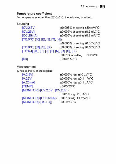
7.2 Accuracy
89Temperature coefficientFor temperatures other than 23°C±5°C, the following is added.Sourcing[CV:2.5V] : ±0.005% of setting ±30 mV/°C[CV:25V] : ±0.005% of setting ±0.2 mV/°C[CC:25mA] : ±0.005% of setting ±0.2 mA/°C[TC:0°C] ([K], [E], [J], [T], [N])
: ±0.005% of setting ±0.05°C/°C[TC:0°C] ([R], [S], [B]) : ±0.005% of setting ±0.10°C/°C[TC:RJ] ([K], [E], [J], [T], [N], [R], [S], [B])
: ±0.01% of setting ±0.10°C/°C[Rs] : ±0.005 Ω/°C
Measurement% rdg. is the % of the reading
[V:2.5V] : ±0.005% rdg. ±10 μV/°C[V:25V] : ±0.005% rdg. ±0.1 mV/°C[A:25mA] : ±0.005% rdg. ±0.1 μA/°C[TEMP] : ±0.05°C/°C[MONITOR] ([CV:2.5V], [CV:25V])
: ±0.01% rdg. ±1 μA/°C[MONITOR] ([CC:25mA]) : ±0.01% rdg. +1 mV/°C[MONITOR] ([TC:RJ]) : ±0.05°C/°C
8.1 Troubleshooting
91TransportingWhen sending the instrument for repair, remove the batteriesand pack carefully to prevent damage in transit. Include cushion-ing material so the instrument cannot move within the package.Be sure to include details of the problem. Hioki cannot beresponsible for damage that occurs during shipment.
Maintenance andService Chapter 8
8.1 Troubleshooting
Do not attempt to modify, disassemble or repair the instru-ment; as fire, electric shock and injury could result.
• If damage is suspected, check the "Before returningfor repair" (p.93) before contacting your dealer orHioki representative.
• Getting the instrument wet or letting oil or dust enterinside its casing will certainly damage it, and is quitelikely to cause an electric shock accident or a danger-ous conflagration. If the instrument has gotten seri-ously wet, oily, or dusty, stop using it and send it forservice at an approved Hioki calibration facility.
8.1 Troubleshooting
92Replaceable Parts and Operating LifetimesUseful life depends on the operating environment and frequencyof use. Operation cannot be guaranteed beyond the followingperiods. For replacement parts, contact your dealer or Hioki rep-resentative.There is a fuse inside in the power unit of the instrument. If thepower does not turn on, the fuse may be blown. If this occurs, areplacement or repair cannot be performed by customers.Please contact your dealer or Hioki representative.
Part Life
Electrolytic Capacitors Approx. 9 years
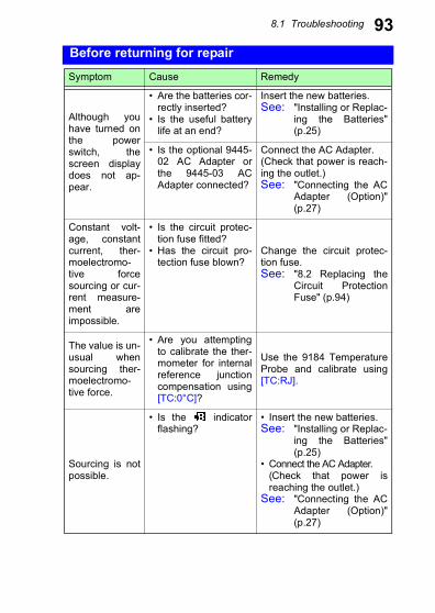
8.1 Troubleshooting
93Before returning for repairSymptom Cause Remedy
Although youhave turned onthe powerswitch, thescreen displaydoes not ap-pear.
• Are the batteries cor-rectly inserted?
• Is the useful batterylife at an end?
Insert the new batteries.See: "Installing or Replac-
ing the Batteries"(p.25)
• Is the optional 9445-02 AC Adapter orthe 9445-03 ACAdapter connected?
Connect the AC Adapter.(Check that power is reach-ing the outlet.)See: "Connecting the AC
Adapter (Option)"(p.27)
Constant volt-age, constantcurrent, ther-moelectromo-tive forcesourcing or cur-rent measure-ment areimpossible.
• Is the circuit protec-tion fuse fitted?
• Has the circuit pro-tection fuse blown?
Change the circuit protec-tion fuse.See: "8.2 Replacing the
Circuit ProtectionFuse" (p.94)
The value is un-usual whensourcing ther-moelectromo-tive force.
• Are you attemptingto calibrate the ther-mometer for internalreference junctioncompensation using[TC:0°C]?
Use the 9184 TemperatureProbe and calibrate using[TC:RJ].
Sourcing is notpossible.
• Is the indicatorflashing?
• Insert the new batteries.See: "Installing or Replac-
ing the Batteries"(p.25)
• Connect the AC Adapter.(Check that power isreaching the outlet.)
See: "Connecting the ACAdapter (Option)"(p.27)
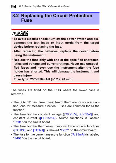
8.2 Replacing the Circuit Protection Fuse
94The fuses are fitted on the PCB where the lower case isremoved.
• The SS7012 has three fuses: two of them are for source func-tion, one for measure function. Fuses are common for all thefunction.
• The fuse for the constant voltage ([CV:2.5V], [CV:25V]) andconstant current ([CC:25mA]) source functions is labeled"F201" on the circuit board.
• The fuse for the thermoelectromotive force source functions([TC:0°C] and [TC:RJ]) is labeled "F202" on the circuit board.
• The fuse for the current measure function ([A:25mA]) is labeled"F401" on the circuit board.
8.2 Replacing the Circuit Protection Fuse
• To avoid electric shock, turn off the power switch and dis-connect the test leads or input cords from the targetdevice before replacing the fuse.
• After replacing the batteries, replace the cover beforeusing the instrument.
• Replace the fuse only with one of the specified character-istics and voltage and current ratings. Never use unspeci-fied fuses and never use the instrument after the fuseholder has shorted. This will damage the instrument andcause injury.Fuse type: 250VF50mAH (φ5.2 × 20 mm)
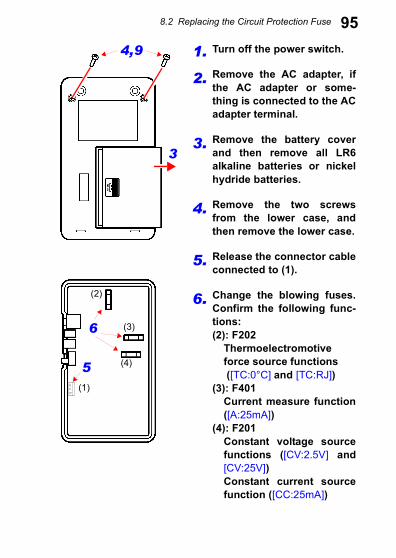
8.2 Replacing the Circuit Protection Fuse
951. Turn off the power switch.
2. Remove the AC adapter, ifthe AC adapter or some-thing is connected to the ACadapter terminal.
3. Remove the battery coverand then remove all LR6alkaline batteries or nickelhydride batteries.
4. Remove the two screwsfrom the lower case, andthen remove the lower case.
5. Release the connector cableconnected to (1).
6. Change the blowing fuses.Confirm the following func-tions:(2): F202
Thermoelectromotiveforce source functions ([TC:0°C] and [TC:RJ])
(3): F401Current measure function([A:25mA])
(4): F201Constant voltage sourcefunctions ([CV:2.5V] and[CV:25V])Constant current sourcefunction ([CC:25mA])
3
4,9
(2)
5
6
(1)
(3)
(4)
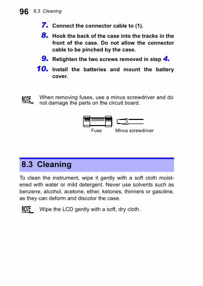
8.3 Cleaning
967. Connect the connector cable to (1).8. Hook the back of the case into the tracks in thefront of the case. Do not allow the connectorcable to be pinched by the case.
9. Retighten the two screws removed in step 4.
10. Install the batteries and mount the batterycover.
To clean the instrument, wipe it gently with a soft cloth moist-ened with water or mild detergent. Never use solvents such asbenzene, alcohol, acetone, ether, ketones, thinners or gasoline,as they can deform and discolor the case.
When removing fuses, use a minus screwdriver and donot damage the parts on the circuit board.
Fuse Minus screwdriver
8.3 Cleaning
Wipe the LCD gently with a soft, dry cloth.
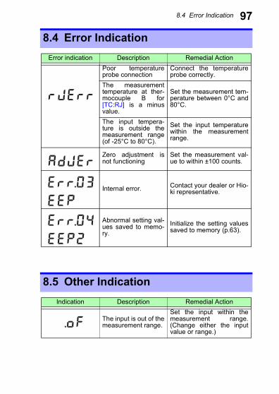
8.4 Error Indication
978.4 Error IndicationError indication Description Remedial Action
Poor temperatureprobe connection
Connect the temperatureprobe correctly.
The measurementtemperature at ther-mocouple B for[TC:RJ] is a minusvalue.
Set the measurement tem-perature between 0°C and80°C.
The input tempera-ture is outside themeasurement range(of -25°C to 80°C).
Set the input temperaturewithin the measurementrange.
Zero adjustment isnot functioning
Set the measurement val-ue to within ±100 counts.
Internal error. Contact your dealer or Hio-ki representative.
Abnormal setting val-ues saved to memo-ry.
Initialize the setting valuessaved to memory (p.63).
8.5 Other Indication
SOURCE ON OFF
MEASURE MONITOR ADJ RMT
K
V
Cm
C
E J T R S B
SOURCE ON OFF K
V
Cm
E J T R S B
SOURCE ON OFF
MEASURE MONITOR ADJ RMT
K
V
Cm
V
Cm
E J T R S B
SOU C O O
MEASURE MONITOR ADJ RMT
K
V
Cm
V
Cm
E J T R S B
Indication Description Remedial Action
The input is out of themeasurement range.
Set the input within themeasurement range.(Change either the inputvalue or range.)
MEASURE MONITOR ADJ RMT
V
Cm
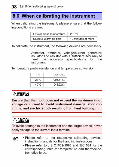
8.6 When calibrating the instrument
98When calibrating the instrument, please ensure that the follow-ing conditions are met.
To calibrate the instrument, the following devices are necessary.
Voltmeter, ammeter, voltage/current generator,insulator and resistor with a sufficient accuracy tomeet the accuracy specifications for theinstrument
Temperature probe resistance and temperature conversion
8.6 When calibrating the instrument
Environment Temperature 23±5°C
SS7012 Warm-up time 10 minutes or more
0°C 918.57 Ω
23°C 993.51 Ω
40°C 1048.52 Ω
Ensure that the input does not exceed the maximum inputvoltage or current to avoid instrument damage, short-cir-cuiting and electric shock resulting from heat building.
To avoid damage to the instrument and the target device, neverapply voltage to the current input terminal.
• Please refer to the respective calibrating devices'instruction manuals for the handling instructions.
• Please refer to JIS C1602-1995 and IEC 584 for thecorresponding table for temperature and thermoelec-tromotive force.
Index 1
Numerics0 ADJ key .........................210°C Check ........................5024 V Loop Power ..............79
AA:25mA .............................68AC Adapter Terminal ........16ADDRESS keys ..........59, 61AdJEr ..........................70, 97
CCC:25mA ..........................39Cleaning ...........................96Communication Function ..81Current Input Terminal .....18CV:2.5V ............................39CV:25V .............................39
DDefault Memory Values ....63Distributor Test .................76
EENTER key .......................21Error Indication .................97
FFlashing Setting Value .....65
IInitializing Memory ........... 63INTERVAL keys ............... 61
LLoad Current .................... 53Load Voltage .................... 53LOCAL key ....................... 21Loop Test ......................... 75
MMEASURE ....................... 19MEASURE FUNCTION key ......................................... 21Measurement (Current) .... 68Measurement (Temperature) ......................................... 71Measurement (Voltage) .... 68Measurement Range ........ 67MEMORY key ...... 21, 59, 61Memory Source Function . 54MEMORY WRITE ............ 55Memory Write Mode ......... 55MONITOR ........................ 19Monitor ............................. 51MONITOR key .................. 21
OoF ............................... 70, 97Output Monitor ................. 51Output Terminal ............... 18
Index
Index 2RRecall Sourcing ................ 59Reference Junction .......... 43Remote Control ................ 81Replacing the Batteries .... 25Replacing the Fuse .......... 94Resistance Thermometer 50RJ Sensor Terminal ......... 16rJErr ........................... 73, 97RMT ................................. 20
SSaving to Memory ............ 55Scan Sourcing ................. 61SKIP key .......................... 21Skip Setting ...................... 57SOURCE FUNCTION key 22Sourcing (Constant Current) ......................................... 39Sourcing (Constant Voltage) ......................................... 39Sourcing (Thermoelectromotive Force) .......................................... 43Sourcing Range ............... 38Standard Resistance ....... 50
TTC:0°C ............................. 43TC:RJ ............................... 44TC TYPE key ................... 22TEMP ............................... 71Temperature Coefficient .. 89Terminal for the Standard Resistor ........... 18
Testing a Two-wire Transmitter .......79Thermocouple ...................43Thermometer Calibration ..43Two-wire Transmitter Simulation ........................76
UUnusual value in sourcing thermoelectromotive force ..........................................93USB Port ...........................16
VV:2.5V ...............................68V:25V ................................68Voltage Input Terminal .....18
ZZero Adjustment .........69, 70
Test
Equipment Depot - 800.517.8431 - 99 Washington Street Melrose, MA 02176TestEquipmentDepot.com