Embed Size (px)
Citation preview
Copyright Safari 4x4 Engineering Pty Ltd Melbourne Victoria Australia – www.safari4x4.com.au Page 1 of 15
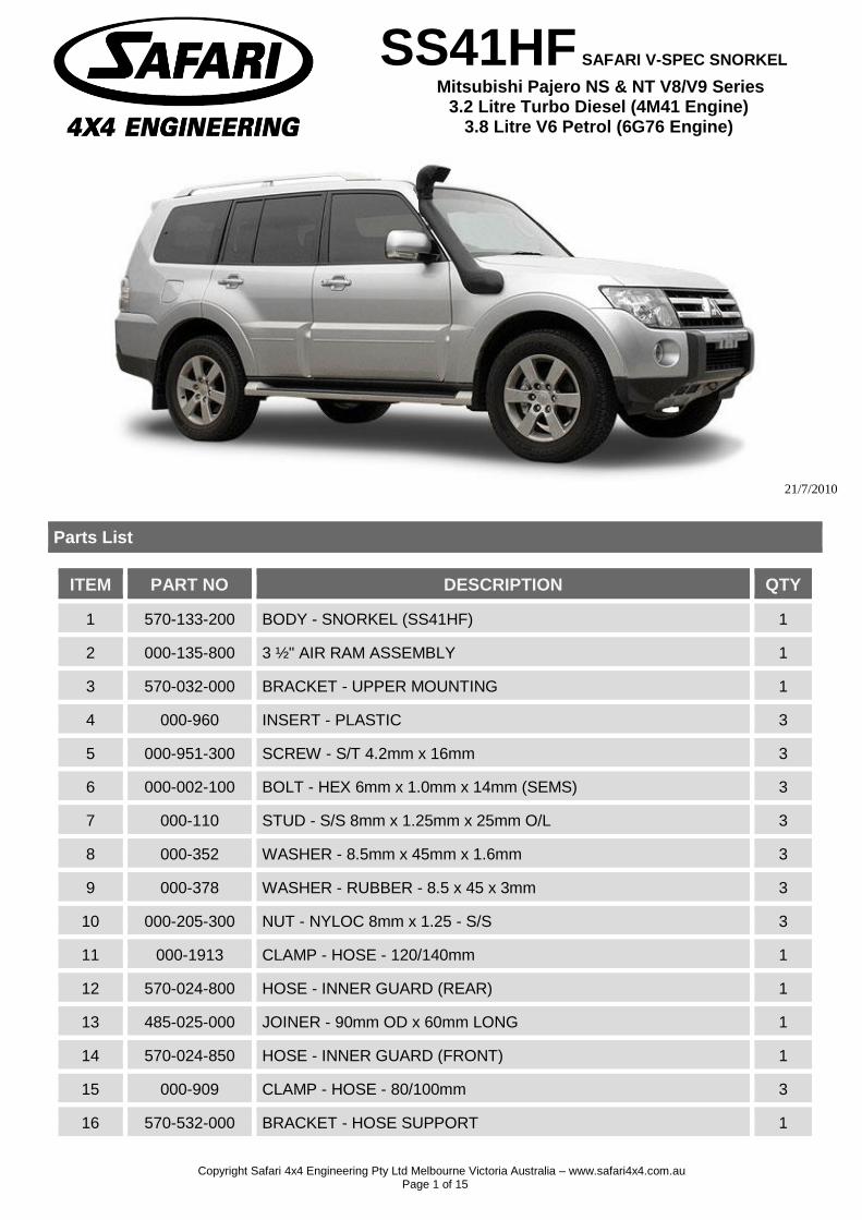
SS41HF SAFARI V-SPEC SNORKEL
Mitsubishi Pajero NS & NT V8/V9 Series 3.2 Litre Turbo Diesel (4M41 Engine)
3.8 Litre V6 Petrol (6G76 Engine)
21/7/2010
Parts List
ITEM PART NO DESCRIPTION QTY
1 570-133-200 BODY - SNORKEL (SS41HF) 1
2 000-135-800 3 ½" AIR RAM ASSEMBLY 1
3 570-032-000 BRACKET - UPPER MOUNTING 1
4 000-960 INSERT - PLASTIC 3
5 000-951-300 SCREW - S/T 4.2mm x 16mm 3
6 000-002-100 BOLT - HEX 6mm x 1.0mm x 14mm (SEMS) 3
7 000-110 STUD - S/S 8mm x 1.25mm x 25mm O/L 3
8 000-352 WASHER - 8.5mm x 45mm x 1.6mm 3
9 000-378 WASHER - RUBBER - 8.5 x 45 x 3mm 3
10 000-205-300 NUT - NYLOC 8mm x 1.25 - S/S 3
11 000-1913 CLAMP - HOSE - 120/140mm 1
12 570-024-800 HOSE - INNER GUARD (REAR) 1
13 485-025-000 JOINER - 90mm OD x 60mm LONG 1
14 570-024-850 HOSE - INNER GUARD (FRONT) 1
15 000-909 CLAMP - HOSE - 80/100mm 3
16 570-532-000 BRACKET - HOSE SUPPORT 1
Copyright Safari 4x4 Engineering Pty Ltd Melbourne Victoria Australia – www.safari4x4.com.au Page 2 of 15
17 565-123-000 DUCT - AIR CLEANER ENTRY (SS35HF) 1
18 000-987-550 CABLE - TIE 8mm x 500mm 1
19 000-958-400 POP RIVET - 4.8mm x 21mm 1
20 565-017-100 FIXTURE - HOLESAW CENTRE 1
21 000-958 POP RIVET - 4mm x 12mm 2
22 565-031-000 BRACKET - AIR CLEANER RELOCATION 1
23 565-031-100 BRACKET - AIR CLEANER RELOCATION 1
24 000-335 WASHER - BODY 8mm x 24mm x 3mm 3
25 000-039-300 BOLT - B/H SOCKET SCREW - 6mm x 16mm 3
26 570-704-000 PLATE - INDICATOR BLANK-OFF 1
27 000-914/B HOSE CLAMP - SIZE 56 (BLACK) 1
28 570-016-200 GASKET - FOAM BODY (SELF ADHESIVE) 1
29 570-017-200 TEMPLATE - GUARD PANEL 1
30 570-098-200 WASHER BOTTLE - PLASTIC 1
31 570-096-000 BRACKET - WASHER BOTTLE MOUNTING 1
32 570-096-100 CLAMP - WASHER BOTTLE MOUNTING 1
33 570-096-200 BRACKET - WASHER BOTTLE SUPPORT 1
34 000-003 BOLT - HEX - 6mm x 1.0 x 20mm 2
35 000-304 WASHER - STAR - 6mm - S/S 2
36 000-321 WASHER - BODY - 6mm x 20mm 2
37 000-003-100 BOLT - HEX - 6mm x 20mm (SEMS) 1
38 000-021 BOLT - HEX - 5mm x 0.8 x 12mm 2
39 000-320 WASHER - FLAT - 5mm 4
40 000-221 NUT - NYLOC - 5mm x 0.8 2
41 000-987-100 CABLE TIE - 2.5mm x 100mm 8
42 000-979 CONNECTOR - STRAIGHT - 5.0mm 1
43 000-826-130 HOSE - WINDSCREEN WASHER - 4mm ID x 1300mm 1
44 570-083-000 LOOM - WASHER BOTTLE MOTOR EXTENSION 1
45 000-987-178 CABLE TIE - 4.5mm x 180mm 2
Copyright Safari 4x4 Engineering Pty Ltd Melbourne Victoria Australia – www.safari4x4.com.au Page 3 of 15
SS41HF SAFARI V-SPEC SNORKEL
Mitsubishi Pajero NS & NT V8/V9 Series 3.2 Litre Turbo Diesel (4M41 Engine)
3.8 Litre V6 Petrol (6G76 Engine)
Installation Guide
Fitment to:
Right Hand Side
Fitting Time:
240 min on models with guard mounted indicator lights
210 min on models with mirrors that have integrated indicator lights
Special Tools:
83 mm & 105 mm diameter hole saw
Step drill Body saw
(reciprocating) Pop-Rivet Gun
Touch-up Paint
Loctite 243 (thread lock)
Sikaflex 227 (adhesive sealant)
Masking Tape
Loctite 406 (Instant Adhesive)
Prior to commencing the installation, it is the installer's responsibility to verify that all components and particularly the guard panel template (Item 29) are correct.
1 V6 Petrol models only: The following installation steps are not required when installing the Safari Snorkel to the specified V6 Petrol engine;
Steps 14 & 15 (parts of only) and steps 24 & 25.
V6 Petrol Installation notes: Due to the air cleaner housing being relocated 25mm backwards as part of the snorkel installation, the standard hose from the air cleaner to the engine is slightly under tension when installed (the standard hose could possibly be shortened by approximately 10mm and a different type of hose clamp used if necessary to reduce some tension off the standard hose).
2 Remove the following in accordance with the factory service manual:
RHS Front mud flap
RHS inner guard liner RHS Guard mounted indicator (if fitted)
Air intake ducting
Air cleaner assembly
Air cleaner housing mounting bracket
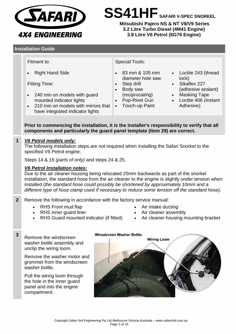
3 Remove the windscreen washer bottle assembly and unclip the wiring loom.
Remove the washer motor and grommet from the windscreen washer bottle.
Pull the wiring loom through the hole in the inner guard panel and into the engine compartment.
Copyright Safari 4x4 Engineering Pty Ltd Melbourne Victoria Australia – www.safari4x4.com.au Page 4 of 15
4
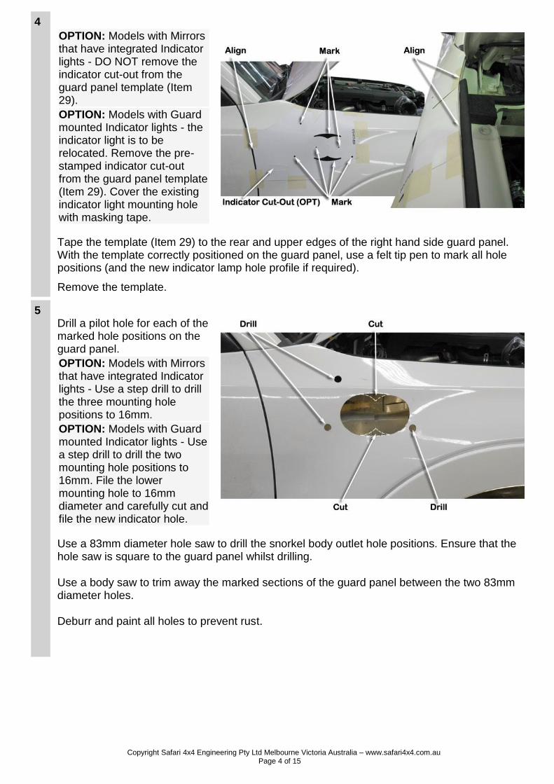
OPTION: Models with Mirrors that have integrated Indicator lights - DO NOT remove the indicator cut-out from the guard panel template (Item 29).
OPTION: Models with Guard mounted Indicator lights - the indicator light is to be relocated. Remove the pre-stamped indicator cut-out from the guard panel template (Item 29). Cover the existing indicator light mounting hole with masking tape.
Tape the template (Item 29) to the rear and upper edges of the right hand side guard panel. With the template correctly positioned on the guard panel, use a felt tip pen to mark all hole positions (and the new indicator lamp hole profile if required).
Remove the template.
5 Drill a pilot hole for each of the marked hole positions on the guard panel.
OPTION: Models with Mirrors that have integrated Indicator lights - Use a step drill to drill the three mounting hole positions to 16mm.
OPTION: Models with Guard mounted Indicator lights - Use a step drill to drill the two mounting hole positions to 16mm. File the lower mounting hole to 16mm diameter and carefully cut and file the new indicator hole.
Use a 83mm diameter hole saw to drill the snorkel body outlet hole positions. Ensure that the hole saw is square to the guard panel whilst drilling.
Use a body saw to trim away the marked sections of the guard panel between the two 83mm diameter holes.
Deburr and paint all holes to prevent rust.
Copyright Safari 4x4 Engineering Pty Ltd Melbourne Victoria Australia – www.safari4x4.com.au Page 5 of 15
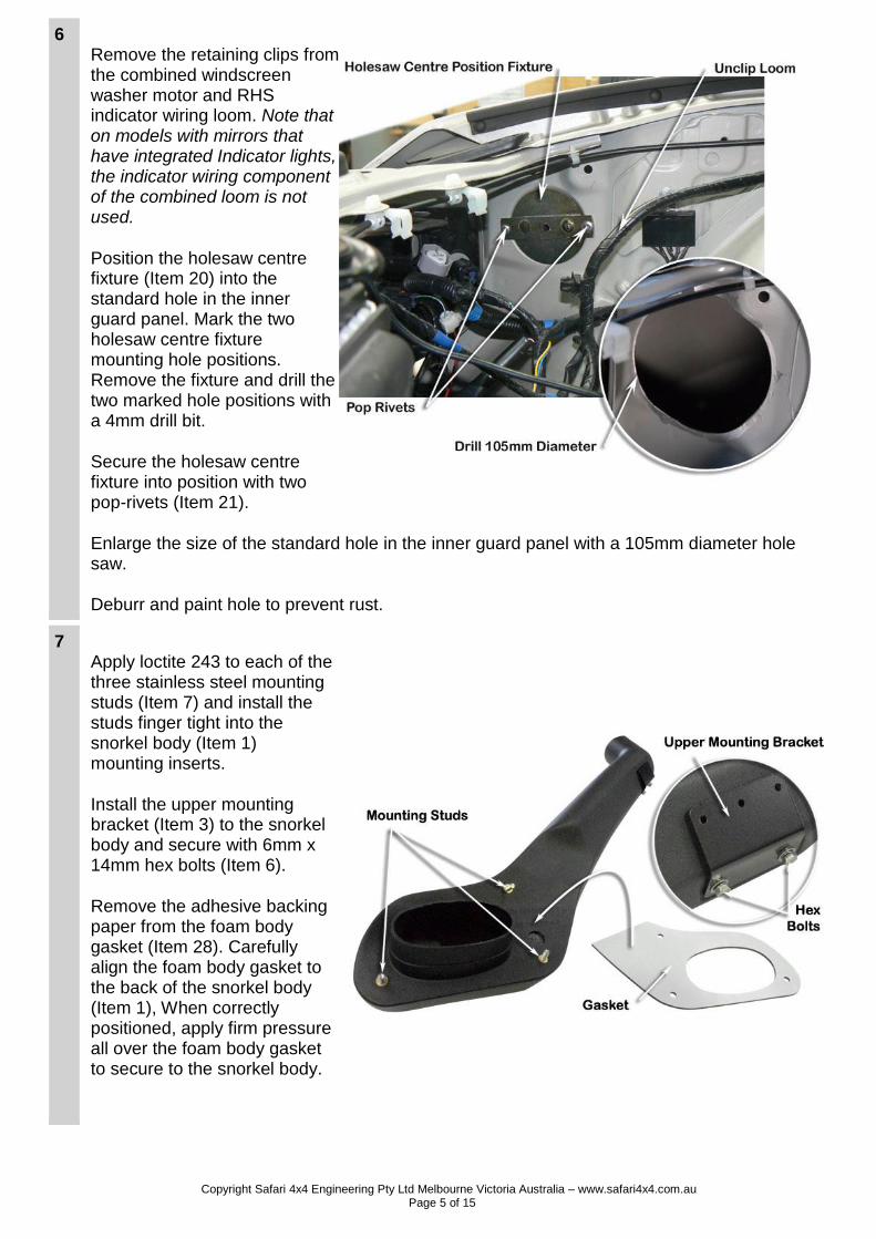
6 Remove the retaining clips from the combined windscreen washer motor and RHS indicator wiring loom. Note that on models with mirrors that have integrated Indicator lights, the indicator wiring component of the combined loom is not used.
Position the holesaw centre fixture (Item 20) into the standard hole in the inner guard panel. Mark the two holesaw centre fixture mounting hole positions. Remove the fixture and drill the two marked hole positions with a 4mm drill bit.
Secure the holesaw centre fixture into position with two pop-rivets (Item 21).
Enlarge the size of the standard hole in the inner guard panel with a 105mm diameter hole saw.
Deburr and paint hole to prevent rust.
7 Apply loctite 243 to each of the three stainless steel mounting studs (Item 7) and install the studs finger tight into the snorkel body (Item 1) mounting inserts.
Install the upper mounting bracket (Item 3) to the snorkel body and secure with 6mm x 14mm hex bolts (Item 6).
Remove the adhesive backing paper from the foam body gasket (Item 28). Carefully align the foam body gasket to the back of the snorkel body (Item 1), When correctly positioned, apply firm pressure all over the foam body gasket to secure to the snorkel body.
Copyright Safari 4x4 Engineering Pty Ltd Melbourne Victoria Australia – www.safari4x4.com.au Page 6 of 15
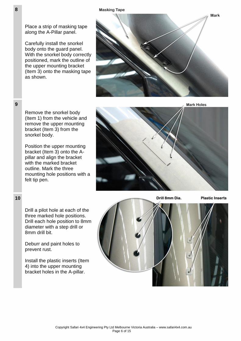
8
Place a strip of masking tape along the A-Pillar panel.
Carefully install the snorkel body onto the guard panel. With the snorkel body correctly positioned, mark the outline of the upper mounting bracket (Item 3) onto the masking tape as shown.
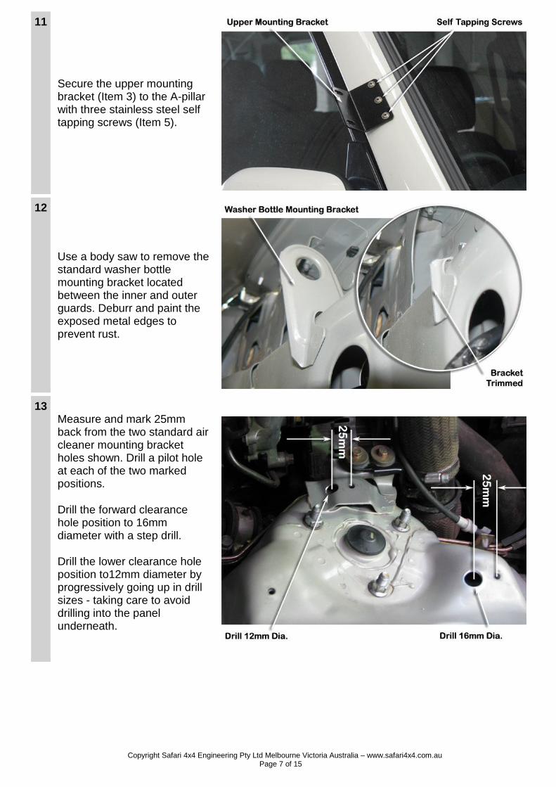
9
Remove the snorkel body (Item 1) from the vehicle and remove the upper mounting bracket (Item 3) from the snorkel body.
Position the upper mounting bracket (Item 3) onto the A-pillar and align the bracket with the marked bracket outline. Mark the three mounting hole positions with a felt tip pen.
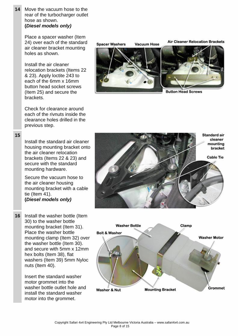
10
Drill a pilot hole at each of the three marked hole positions. Drill each hole position to 8mm diameter with a step drill or 8mm drill bit.
Deburr and paint holes to prevent rust.
Install the plastic inserts (Item 4) into the upper mounting bracket holes in the A-pillar.
Copyright Safari 4x4 Engineering Pty Ltd Melbourne Victoria Australia – www.safari4x4.com.au Page 7 of 15
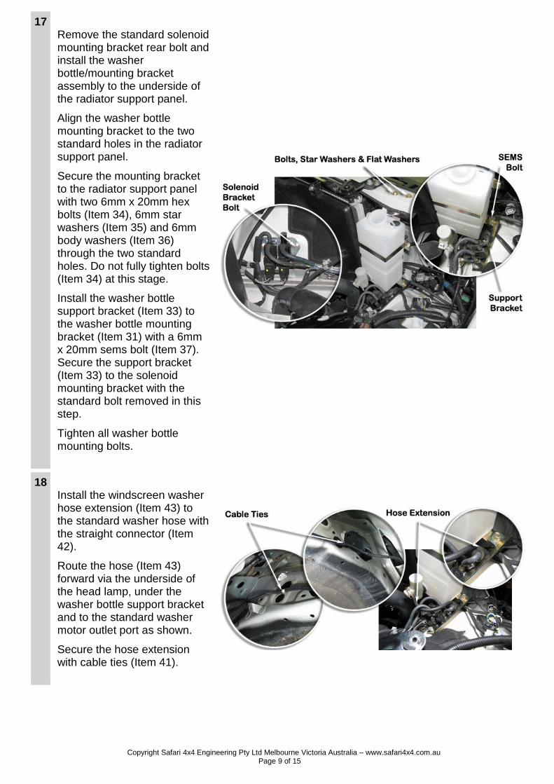
11
Secure the upper mounting bracket (Item 3) to the A-pillar with three stainless steel self tapping screws (Item 5).
12
Use a body saw to remove the standard washer bottle mounting bracket located between the inner and outer guards. Deburr and paint the exposed metal edges to prevent rust.
13 Measure and mark 25mm back from the two standard air cleaner mounting bracket holes shown. Drill a pilot hole at each of the two marked positions.
Drill the forward clearance hole position to 16mm diameter with a step drill.
Drill the lower clearance hole position to12mm diameter by progressively going up in drill sizes - taking care to avoid drilling into the panel underneath.
Copyright Safari 4x4 Engineering Pty Ltd Melbourne Victoria Australia – www.safari4x4.com.au Page 8 of 15
14 Move the vacuum hose to the rear of the turbocharger outlet hose as shown. (Diesel models only)
Place a spacer washer (Item 24) over each of the standard air cleaner bracket mounting holes as shown.
Install the air cleaner relocation brackets (Items 22 & 23). Apply loctite 243 to each of the 6mm x 16mm button head socket screws (Item 25) and secure the brackets.
Check for clearance around each of the rivnuts inside the clearance holes drilled in the previous step.
15
Install the standard air cleaner housing mounting bracket onto the air cleaner relocation brackets (Items 22 & 23) and secure with the standard mounting hardware.
Secure the vacuum hose to the air cleaner housing mounting bracket with a cable tie (Item 41). (Diesel models only)
16 Install the washer bottle (Item 30) to the washer bottle mounting bracket (Item 31). Place the washer bottle mounting clamp (Item 32) over the washer bottle (Item 30). and secure with 5mm x 12mm hex bolts (Item 38), flat washers (Item 39) 5mm Nyloc nuts (Item 40).
Insert the standard washer motor grommet into the washer bottle outlet hole and install the standard washer motor into the grommet.
Copyright Safari 4x4 Engineering Pty Ltd Melbourne Victoria Australia – www.safari4x4.com.au Page 9 of 15
17 Remove the standard solenoid mounting bracket rear bolt and install the washer bottle/mounting bracket assembly to the underside of the radiator support panel.
Align the washer bottle mounting bracket to the two standard holes in the radiator support panel.
Secure the mounting bracket to the radiator support panel with two 6mm x 20mm hex bolts (Item 34), 6mm star washers (Item 35) and 6mm body washers (Item 36) through the two standard holes. Do not fully tighten bolts (Item 34) at this stage.
Install the washer bottle support bracket (Item 33) to the washer bottle mounting bracket (Item 31) with a 6mm x 20mm sems bolt (Item 37). Secure the support bracket (Item 33) to the solenoid mounting bracket with the standard bolt removed in this step.
Tighten all washer bottle mounting bolts.
18 Install the windscreen washer hose extension (Item 43) to the standard washer hose with the straight connector (Item 42).
Route the hose (Item 43) forward via the underside of the head lamp, under the washer bottle support bracket and to the standard washer motor outlet port as shown.
Secure the hose extension with cable ties (Item 41).
Copyright Safari 4x4 Engineering Pty Ltd Melbourne Victoria Australia – www.safari4x4.com.au Page 10 of 15
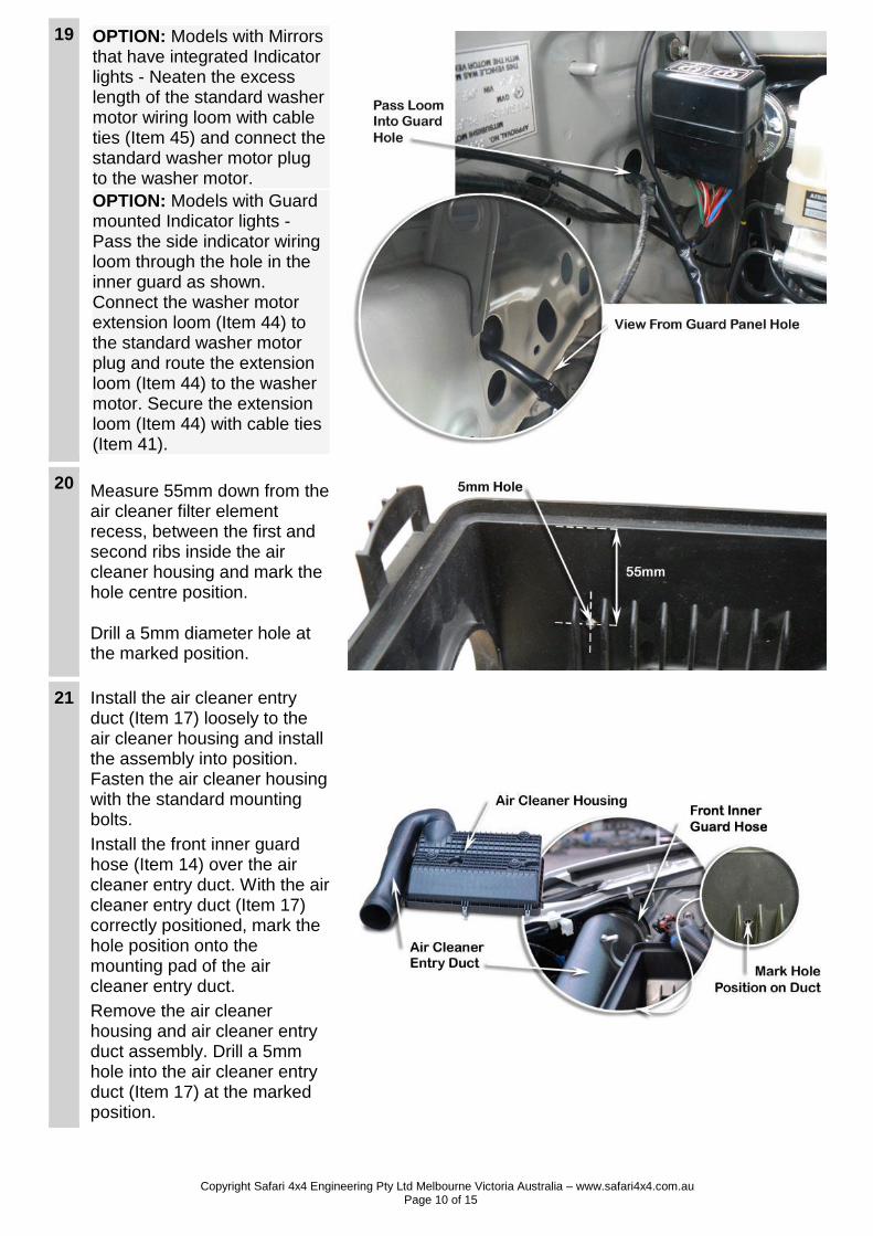
19 OPTION: Models with Mirrors that have integrated Indicator lights - Neaten the excess length of the standard washer motor wiring loom with cable ties (Item 45) and connect the standard washer motor plug to the washer motor.
OPTION: Models with Guard mounted Indicator lights - Pass the side indicator wiring loom through the hole in the inner guard as shown. Connect the washer motor extension loom (Item 44) to the standard washer motor plug and route the extension loom (Item 44) to the washer motor. Secure the extension loom (Item 44) with cable ties (Item 41).
20 Measure 55mm down from the air cleaner filter element recess, between the first and second ribs inside the air cleaner housing and mark the hole centre position.
Drill a 5mm diameter hole at the marked position.
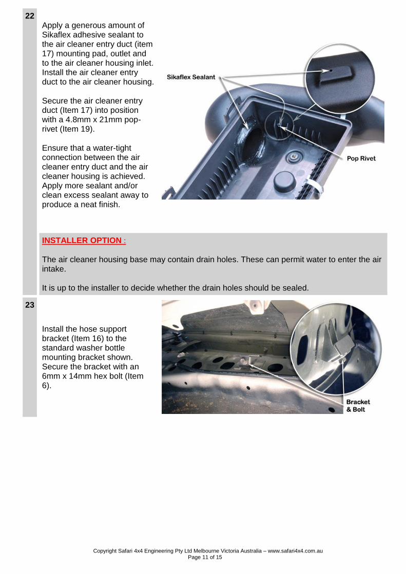
21 Install the air cleaner entry duct (Item 17) loosely to the air cleaner housing and install the assembly into position. Fasten the air cleaner housing with the standard mounting bolts.
Install the front inner guard hose (Item 14) over the air cleaner entry duct. With the air cleaner entry duct (Item 17) correctly positioned, mark the hole position onto the mounting pad of the air cleaner entry duct.
Remove the air cleaner housing and air cleaner entry duct assembly. Drill a 5mm hole into the air cleaner entry duct (Item 17) at the marked position.
Copyright Safari 4x4 Engineering Pty Ltd Melbourne Victoria Australia – www.safari4x4.com.au Page 11 of 15
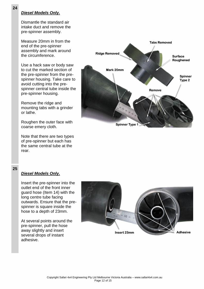
22 Apply a generous amount of Sikaflex adhesive sealant to the air cleaner entry duct (item 17) mounting pad, outlet and to the air cleaner housing inlet. Install the air cleaner entry duct to the air cleaner housing.
Secure the air cleaner entry duct (Item 17) into position with a 4.8mm x 21mm pop-rivet (Item 19).
Ensure that a water-tight connection between the air cleaner entry duct and the air cleaner housing is achieved. Apply more sealant and/or clean excess sealant away to produce a neat finish.
INSTALLER OPTION :
The air cleaner housing base may contain drain holes. These can permit water to enter the air intake.
It is up to the installer to decide whether the drain holes should be sealed.
23
Install the hose support bracket (Item 16) to the standard washer bottle mounting bracket shown. Secure the bracket with an 6mm x 14mm hex bolt (Item 6).
Copyright Safari 4x4 Engineering Pty Ltd Melbourne Victoria Australia – www.safari4x4.com.au Page 12 of 15
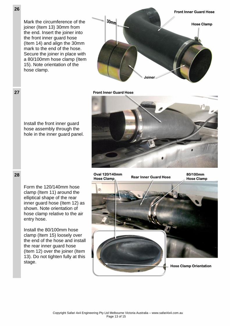
24 Diesel Models Only. Dismantle the standard air intake duct and remove the pre-spinner assembly.
Measure 20mm in from the end of the pre-spinner assembly and mark around the circumference.
Use a hack saw or body saw to cut the marked section of the pre-spinner from the pre-spinner housing. Take care to avoid cutting into the pre-spinner central tube inside the pre-spinner housing.
Remove the ridge and mounting tabs with a grinder or lathe.
Roughen the outer face with coarse emery cloth.
Note that there are two types of pre-spinner but each has the same central tube at the rear.
25 Diesel Models Only. Insert the pre-spinner into the outlet end of the front inner guard hose (Item 14) with the long centre tube facing outwards. Ensure that the pre-spinner is square inside the hose to a depth of 23mm.
At several points around the pre-spinner, pull the hose away slightly and insert several drops of instant adhesive.
Copyright Safari 4x4 Engineering Pty Ltd Melbourne Victoria Australia – www.safari4x4.com.au Page 13 of 15
26
Mark the circumference of the joiner (Item 13) 30mm from the end. Insert the joiner into the front inner guard hose (Item 14) and align the 30mm mark to the end of the hose. Secure the joiner in place with a 80/100mm hose clamp (Item 15). Note orientation of the hose clamp.
27
Install the front inner guard hose assembly through the hole in the inner guard panel.
28
Form the 120/140mm hose clamp (Item 11) around the elliptical shape of the rear inner guard hose (Item 12) as shown. Note orientation of hose clamp relative to the air entry hose.
Install the 80/100mm hose clamp (Item 15) loosely over the end of the hose and install the rear inner guard hose (Item 12) over the joiner (Item 13). Do not tighten fully at this stage.
Copyright Safari 4x4 Engineering Pty Ltd Melbourne Victoria Australia – www.safari4x4.com.au Page 14 of 15
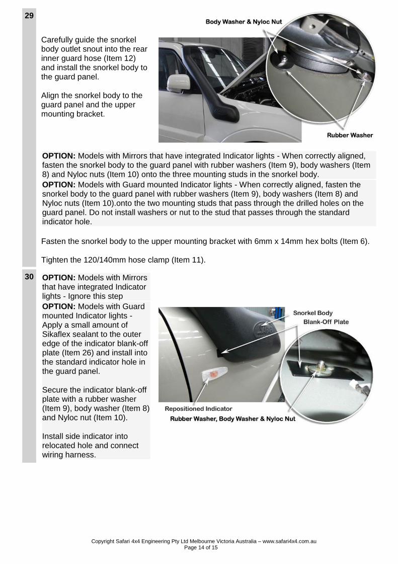
29
Carefully guide the snorkel body outlet snout into the rear inner guard hose (Item 12) and install the snorkel body to the guard panel.
Align the snorkel body to the guard panel and the upper mounting bracket.
OPTION: Models with Mirrors that have integrated Indicator lights - When correctly aligned, fasten the snorkel body to the guard panel with rubber washers (Item 9), body washers (Item 8) and Nyloc nuts (Item 10) onto the three mounting studs in the snorkel body.
OPTION: Models with Guard mounted Indicator lights - When correctly aligned, fasten the snorkel body to the guard panel with rubber washers (Item 9), body washers (Item 8) and Nyloc nuts (Item 10).onto the two mounting studs that pass through the drilled holes on the guard panel. Do not install washers or nut to the stud that passes through the standard indicator hole.
Fasten the snorkel body to the upper mounting bracket with 6mm x 14mm hex bolts (Item 6).
Tighten the 120/140mm hose clamp (Item 11).
30 OPTION: Models with Mirrors that have integrated Indicator lights - Ignore this step
OPTION: Models with Guard mounted Indicator lights - Apply a small amount of Sikaflex sealant to the outer edge of the indicator blank-off plate (Item 26) and install into the standard indicator hole in the guard panel.
Secure the indicator blank-off plate with a rubber washer (Item 9), body washer (Item 8) and Nyloc nut (Item 10).
Install side indicator into relocated hole and connect wiring harness.
Copyright Safari 4x4 Engineering Pty Ltd Melbourne Victoria Australia – www.safari4x4.com.au Page 15 of 15
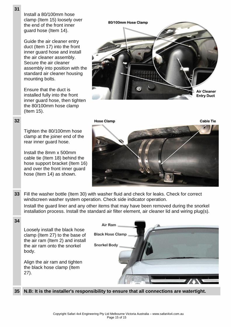
31 Install a 80/100mm hose clamp (Item 15) loosely over the end of the front inner guard hose (Item 14).
Guide the air cleaner entry duct (Item 17) into the front inner guard hose and install the air cleaner assembly. Secure the air cleaner assembly into position with the standard air cleaner housing mounting bolts.
Ensure that the duct is installed fully into the front inner guard hose, then tighten the 80/100mm hose clamp (Item 15).
32
Tighten the 80/100mm hose clamp at the joiner end of the rear inner guard hose.
Install the 8mm x 500mm cable tie (Item 18) behind the hose support bracket (Item 16) and over the front inner guard hose (Item 14) as shown.
33 Fill the washer bottle (Item 30) with washer fluid and check for leaks. Check for correct windscreen washer system operation. Check side indicator operation.
Install the guard liner and any other items that may have been removed during the snorkel installation process. Install the standard air filter element, air cleaner lid and wiring plug(s).
34
Loosely install the black hose clamp (Item 27) to the base of the air ram (Item 2) and install the air ram onto the snorkel body.
Align the air ram and tighten the black hose clamp (Item 27).
35 N.B: It is the installer's responsibility to ensure that all connections are watertight.