Embed Size (px)
Citation preview

SRX1400 Services Gateway
Hardware Guide
Published: 2014-06-03
Copyright © 2014, Juniper Networks, Inc.

Juniper Networks, Inc.1194 North Mathilda AvenueSunnyvale, California 94089USA408-745-2000www.juniper.net
Juniper Networks, Junos, Steel-Belted Radius, NetScreen, and ScreenOS are registered trademarks of Juniper Networks, Inc. in the UnitedStates and other countries. The Juniper Networks Logo, the Junos logo, and JunosE are trademarks of Juniper Networks, Inc. All othertrademarks, service marks, registered trademarks, or registered service marks are the property of their respective owners.
Juniper Networks assumes no responsibility for any inaccuracies in this document. Juniper Networks reserves the right to change, modify,transfer, or otherwise revise this publication without notice.
SRX1400 Services Gateway Hardware GuideCopyright © 2014, Juniper Networks, Inc.All rights reserved. Printed in USA.
Revision HistoryDecember 2012—Moved module details into SRX1400, SRX3400, and SRX3600 Services Gateway Module Guide, add information aboutsupport for second SPC.June 2013—Incorporated additional warnings that the chassis must be connected to earth ground.April 2014—Added the steps to copy certificates when replacing a routing engine in a chassis cluster.June 2014—Added the EMC compliance requirements in Israel and the procedure to perform initial software configuration using J-Web
The information in this document is current as of the date on the title page.
SOFTWARE LICENSE
The terms and conditions for using this software are described in the software license contained in the acknowledgment to your purchaseorder or, to the extent applicable, to any reseller agreement or end-user purchase agreement executed between you and Juniper Networks.By using this software, you indicate that you understand and agree to be bound by those terms and conditions.
Generally speaking, the software license restricts the manner in which you are permitted to use the software and may contain prohibitionsagainst certain uses. The software license may state conditions under which the license is automatically terminated. You should consultthe license for further details.
For complete product documentation, please see the Juniper Networks Web site at www.juniper.net/techpubs.
ENDUSER LICENSE AGREEMENT
The Juniper Networks product that is the subject of this technical documentation consists of (or is intended for use with) Juniper Networkssoftware. Use of such software is subject to the terms and conditions of the End User License Agreement (“EULA”) posted athttp://www.juniper.net/support/eula.html. By downloading, installing or using such software, you agree to the terms and conditions ofthat EULA.
Copyright © 2014, Juniper Networks, Inc.ii

Table of Contents
About This Guide . . . . . . . . . . . . . . . . . . . . . . . . . . . . . . . . . . . . . . . . . . . . . . . . . . xi
Objectives . . . . . . . . . . . . . . . . . . . . . . . . . . . . . . . . . . . . . . . . . . . . . . . . . . . . . . xi
Audience . . . . . . . . . . . . . . . . . . . . . . . . . . . . . . . . . . . . . . . . . . . . . . . . . . . . . . . xi
Documentation Conventions . . . . . . . . . . . . . . . . . . . . . . . . . . . . . . . . . . . . . . . xi
SRX Series Documentation and Release Notes . . . . . . . . . . . . . . . . . . . . . . . xiii
Obtaining Documentation . . . . . . . . . . . . . . . . . . . . . . . . . . . . . . . . . . . . . . . . xiv
Documentation Feedback . . . . . . . . . . . . . . . . . . . . . . . . . . . . . . . . . . . . . . . . xiv
Requesting Technical Support . . . . . . . . . . . . . . . . . . . . . . . . . . . . . . . . . . . . . xiv
Self-Help Online Tools and Resources . . . . . . . . . . . . . . . . . . . . . . . . . . . xiv
Opening a Case with JTAC . . . . . . . . . . . . . . . . . . . . . . . . . . . . . . . . . . . . . xv
Part 1 SRX1400 Services Gateway Overview
Chapter 1 Introduction to the SRX1400 Services Gateway . . . . . . . . . . . . . . . . . . . . . . . . 3
SRX1400 Services Gateway Description . . . . . . . . . . . . . . . . . . . . . . . . . . . . . . . . . . 3
SRX1400 Services Gateway Models . . . . . . . . . . . . . . . . . . . . . . . . . . . . . . . . . . . . . 4
SRX1400 Services Gateway Hardware Features . . . . . . . . . . . . . . . . . . . . . . . . . . . 4
SRX1400 Services Gateway Physical Specifications . . . . . . . . . . . . . . . . . . . . . . . . 5
SRX1400 Services Gateway Environmental Specifications . . . . . . . . . . . . . . . . . . . 7
SRX1400 Services Gateway Features Overview . . . . . . . . . . . . . . . . . . . . . . . . . . . . 7
Understanding the SRX1400 Services Gateway in the Enterprise
Network . . . . . . . . . . . . . . . . . . . . . . . . . . . . . . . . . . . . . . . . . . . . . . . . . . . . 8
Understanding the SRX1400 Services Gateway in the Service Provider
Network . . . . . . . . . . . . . . . . . . . . . . . . . . . . . . . . . . . . . . . . . . . . . . . . . . . . 8
Understanding the SRX1400 Services Gateway in the Data Center . . . . . . . . . 9
Chapter 2 SRX1400 Services Gateway Hardware Components . . . . . . . . . . . . . . . . . . . 11
SRX1400 Services Gateway Component Basics . . . . . . . . . . . . . . . . . . . . . . . . . . . 11
SRX1400 Services Gateway Chassis Slots . . . . . . . . . . . . . . . . . . . . . . . . . . . . 11
Overview of the SRX1400 Services Gateway CFMs . . . . . . . . . . . . . . . . . . . . . 12
Understanding the SRX1400 Services Gateway Data Flow . . . . . . . . . . . . . . . 13
SRX1400 Services Gateway Hardware Components . . . . . . . . . . . . . . . . . . . 14
SRX1400 Services Gateway Front Panel . . . . . . . . . . . . . . . . . . . . . . . . . . . . . 15
SRX1400 Services Gateway Back Panel . . . . . . . . . . . . . . . . . . . . . . . . . . . . . . 16
SRX1400 Services Gateway Backplane . . . . . . . . . . . . . . . . . . . . . . . . . . . . . . 16
SRX1400 Services Gateway SYSIOCs . . . . . . . . . . . . . . . . . . . . . . . . . . . . . . . . . . . 17
Features and Functions . . . . . . . . . . . . . . . . . . . . . . . . . . . . . . . . . . . . . . . . . . . 18
POWER Button Functionality on the System I/O Card . . . . . . . . . . . . . . . . . . 19
LED Indicators on the System I/O Card . . . . . . . . . . . . . . . . . . . . . . . . . . . . . . 19
Front Panel Ports and Connectors on the System I/O Card . . . . . . . . . . . . . . 22
SRX1400 Services Gateway NSPC . . . . . . . . . . . . . . . . . . . . . . . . . . . . . . . . . . . . . 23
iiiCopyright © 2014, Juniper Networks, Inc.

SPCs for the SRX1400 Services Gateway . . . . . . . . . . . . . . . . . . . . . . . . . . . . . . . . 24
NPCs for the SRX1400 Services Gateway . . . . . . . . . . . . . . . . . . . . . . . . . . . . . . . . 26
SRX1400 Services Gateway Routing Engine . . . . . . . . . . . . . . . . . . . . . . . . . . . . . . 27
IOCs and NP-IOCs Supported on the SRX1400 Services Gateway . . . . . . . . . . . . 28
SRX1400 Services Gateway Power Supplies . . . . . . . . . . . . . . . . . . . . . . . . . . . . . 29
SRX1400 Services Gateway Power Supplies Overview . . . . . . . . . . . . . . . . . 29
SRX1400 Services Gateway AC Power Supply . . . . . . . . . . . . . . . . . . . . . . . . 30
AC Power Supply Overview . . . . . . . . . . . . . . . . . . . . . . . . . . . . . . . . . . . . 30
AC Power Supply Electrical Specifications . . . . . . . . . . . . . . . . . . . . . . . . 30
AC Power Supply LEDs . . . . . . . . . . . . . . . . . . . . . . . . . . . . . . . . . . . . . . . . 31
SRX1400 Services Gateway DC Power Supply . . . . . . . . . . . . . . . . . . . . . . . . . 31
DC Power Supply Overview . . . . . . . . . . . . . . . . . . . . . . . . . . . . . . . . . . . . 31
DC Power Supply Electrical Specifications . . . . . . . . . . . . . . . . . . . . . . . . 32
DC Power Supply LEDs . . . . . . . . . . . . . . . . . . . . . . . . . . . . . . . . . . . . . . . 32
SRX1400 Services Gateway Cooling System . . . . . . . . . . . . . . . . . . . . . . . . . . . . . 33
Part 2 Setting Up the SRX1400 Services Gateway
Chapter 3 Preparing the Site for SRX1400 Services Gateway Installation . . . . . . . . . . 37
Site Preparation Checklist for the SRX1400 Services Gateway . . . . . . . . . . . . . . . 37
SRX1400 Services Gateway Rack, Cabinet, and Airflow Clearance
Requirements . . . . . . . . . . . . . . . . . . . . . . . . . . . . . . . . . . . . . . . . . . . . . . . . . . 38
SRX1400 Services Gateway Cabinet Requirements . . . . . . . . . . . . . . . . . . . . 39
Cabinet Size and Clearance Requirements . . . . . . . . . . . . . . . . . . . . . . . 39
Cabinet Airflow Requirements . . . . . . . . . . . . . . . . . . . . . . . . . . . . . . . . . 39
SRX1400 Services Gateway Rack Requirements . . . . . . . . . . . . . . . . . . . . . . 40
SRX1400 Services Gateway Rack Size and Strength Requirements . . . 40
SRX1400 Services Gateway Spacing of Mounting Bracket Holes . . . . . . 41
Connecting the SRX1400 Services Gateway to the Building
Structure . . . . . . . . . . . . . . . . . . . . . . . . . . . . . . . . . . . . . . . . . . . . . . . 41
Clearance Requirements for Airflow and Hardware Maintenance of the
SRX1400 Services Gateway . . . . . . . . . . . . . . . . . . . . . . . . . . . . . . . . . . . 42
Chapter 4 Unpacking the SRX1400 Services Gateway . . . . . . . . . . . . . . . . . . . . . . . . . . 43
Required Tools and Parts for Unpacking the SRX1400 Services Gateway . . . . . . 43
Unpacking the SRX1400 Services Gateway . . . . . . . . . . . . . . . . . . . . . . . . . . . . . . 43
Verifying Parts Received with the SRX1400 Services Gateway . . . . . . . . . . . . . . . 45
Copyright © 2014, Juniper Networks, Inc.iv
SRX1400 Services Gateway Hardware Guide

Chapter 5 Installing the SRX1400 Services Gateway . . . . . . . . . . . . . . . . . . . . . . . . . . . . 47
Installation Overview for the SRX1400 Services Gateway . . . . . . . . . . . . . . . . . . . 47
SRX1400 Services Gateway Safety Requirements, Warnings, and Guidelines . . . 48
Required Tools for Installing the SRX1400 Services Gateway . . . . . . . . . . . . . . . . 49
Preparing the SRX1400 Services Gateway for Rack-Mount or Cabinet
Installation . . . . . . . . . . . . . . . . . . . . . . . . . . . . . . . . . . . . . . . . . . . . . . . . . . . . 49
Installing the Mounting Hardware for the SRX1400 Services Gateway . . . . . . . . 50
Installing the SRX1400 Services Gateway in a Rack or Cabinet Using a Mechanical
Lift . . . . . . . . . . . . . . . . . . . . . . . . . . . . . . . . . . . . . . . . . . . . . . . . . . . . . . . . . . . 50
Installing the SRX1400 Services Gateway in a Rack or Cabinet Manually (Without
a Mechanical Lift) . . . . . . . . . . . . . . . . . . . . . . . . . . . . . . . . . . . . . . . . . . . . . . . 53
Installing the SRX1400 Services Gateway in a Rack or Cabinet Manually . . . 53
Required Tools for Installing the SRX1400 Services Gateway Manually . . . . 54
Removing Components from the Chassis for Manual Lifting of the SRX1400
Services Gateway . . . . . . . . . . . . . . . . . . . . . . . . . . . . . . . . . . . . . . . . . . . 54
Lifting the SRX1400 Services Gateway Chassis into a Rack . . . . . . . . . . . . . . 55
Reinstalling Components into the SRX1400 Services Gateway Chassis . . . . 57
Chapter 6 Installing Additional Components into the SRX1400 ServicesGateway . . . . . . . . . . . . . . . . . . . . . . . . . . . . . . . . . . . . . . . . . . . . . . . . . . . . . . . . . 59
Installing a Network and Services Processing Card in an SRX1400 Services
Gateway . . . . . . . . . . . . . . . . . . . . . . . . . . . . . . . . . . . . . . . . . . . . . . . . . . . . . . 59
Installing an SPC in an SRX1400 Services Gateway . . . . . . . . . . . . . . . . . . . . . . . . 61
Installing an NPC in an SRX1400 Services Gateway . . . . . . . . . . . . . . . . . . . . . . . 63
Installing an IOC or NP-IOC in an SRX1400 Services Gateway . . . . . . . . . . . . . . . 65
Installing a System I/O Card into the SRX1400 Services Gateway . . . . . . . . . . . . 67
Installing an AC Power Supply in the SRX1400 Services Gateway . . . . . . . . . . . . 68
Installing a DC Power Supply in the SRX1400 Services Gateway . . . . . . . . . . . . . 69
Chapter 7 Connecting the SRX1400 Services Gateway . . . . . . . . . . . . . . . . . . . . . . . . . . 71
Connecting the SRX1400 Services Gateway to a Management Device . . . . . . . . . 71
Connecting the SRX1400 Services Gateway to a Network for Out-of-Band
Management . . . . . . . . . . . . . . . . . . . . . . . . . . . . . . . . . . . . . . . . . . . . . . . . 71
Connecting the SRX1400 Services Gateway to a Management Console or
an Auxiliary Device . . . . . . . . . . . . . . . . . . . . . . . . . . . . . . . . . . . . . . . . . . . 72
Chapter 8 Grounding and Providing Power to the SRX1400 Services Gateway . . . . . . 75
Required Tools and Parts for Grounding and Providing Power to the SRX1400
Services Gateway . . . . . . . . . . . . . . . . . . . . . . . . . . . . . . . . . . . . . . . . . . . . . . . 75
Grounding the SRX1400 Services Gateway . . . . . . . . . . . . . . . . . . . . . . . . . . . . . . 76
Connecting the SRX1400 Services Gateway to an AC Power Supply . . . . . . . . . . 77
Connecting the SRX1400 Services Gateway to a DC Power Supply . . . . . . . . . . . 80
Powering On the SRX1400 Services Gateway . . . . . . . . . . . . . . . . . . . . . . . . . . . . . 81
Powering Off the SRX1400 Services Gateway . . . . . . . . . . . . . . . . . . . . . . . . . . . . 82
vCopyright © 2014, Juniper Networks, Inc.
Table of Contents

Chapter 9 Performing Initial Software Configuration on the SRX1400 ServicesGateway . . . . . . . . . . . . . . . . . . . . . . . . . . . . . . . . . . . . . . . . . . . . . . . . . . . . . . . . . 85
SRX1400 Services Gateway Software Configuration Overview . . . . . . . . . . . . . . . 85
Performing Initial Software Configuration on the SRX1400 Services Gateway
(CLI Procedure) . . . . . . . . . . . . . . . . . . . . . . . . . . . . . . . . . . . . . . . . . . . . . . . . 86
Performing Initial Software Configuration Using J-Web . . . . . . . . . . . . . . . . . . . . 90
Configuring Root Authentication and the Management Interface from the
CLI . . . . . . . . . . . . . . . . . . . . . . . . . . . . . . . . . . . . . . . . . . . . . . . . . . . . . . . 90
Configuring Interfaces, Zones, and Policies with J-Web . . . . . . . . . . . . . . . . . . 91
Configuring the Hostname . . . . . . . . . . . . . . . . . . . . . . . . . . . . . . . . . . . . 92
Configuring Interfaces . . . . . . . . . . . . . . . . . . . . . . . . . . . . . . . . . . . . . . . . 92
Configuring Zones and Assigning Interfaces . . . . . . . . . . . . . . . . . . . . . . . 92
Configuring Security Policies . . . . . . . . . . . . . . . . . . . . . . . . . . . . . . . . . . . 93
Part 3 SRX1400 Services Gateway Hardware Maintenance,Replacement, and Troubleshooting Procedures
Chapter 10 Maintaining the SRX1400 Services Gateway Hardware Components . . . . 97
Required Tools and Parts for Maintaining the SRX1400 Services Gateway
Hardware Components . . . . . . . . . . . . . . . . . . . . . . . . . . . . . . . . . . . . . . . . . . 97
Routine Maintenance Procedures for the SRX1400 Services Gateway . . . . . . . . . 98
Maintaining the Air Filter on the SRX1400 Services Gateway . . . . . . . . . . . . . . . . 98
Maintaining the Fan Tray on the SRX1400 Services Gateway . . . . . . . . . . . . . . . . 99
Maintaining the Routing Engine on the SRX1400 Services Gateway . . . . . . . . . . 100
Maintaining Power Supplies on the SRX1400 Services Gateway . . . . . . . . . . . . . 101
Chapter 11 Troubleshooting the SRX1400 Services Gateway . . . . . . . . . . . . . . . . . . . . 103
Troubleshooting Hardware Components on the SRX1400 Services Gateway . . 103
Troubleshooting with the CLI on the SRX1400 Services Gateway . . . . . . . . 103
Troubleshooting with LEDs on the SRX1400 Services Gateway . . . . . . . . . . 105
Troubleshooting with Chassis and Interface Alarm Messages on the SRX1400
Services Gateway . . . . . . . . . . . . . . . . . . . . . . . . . . . . . . . . . . . . . . . . . . . 106
Juniper Networks Technical Assistance Center . . . . . . . . . . . . . . . . . . . . . . . . . . . 107
Troubleshooting the Cooling System on the SRX1400 Services Gateway . . . . . . 107
Troubleshooting I/O Cards on the SRX1400 Services Gateway . . . . . . . . . . . . . . 108
Troubleshooting the System I/O Card on the SRX1400 Services Gateway . . . . . 109
Troubleshooting the Network and Services Processing Card on the SRX1400
Services Gateway . . . . . . . . . . . . . . . . . . . . . . . . . . . . . . . . . . . . . . . . . . . . . . . 110
Troubleshooting Services Processing Cards on the SRX1400 Services
Gateway . . . . . . . . . . . . . . . . . . . . . . . . . . . . . . . . . . . . . . . . . . . . . . . . . . . . . . . 111
Troubleshooting an NPC on the SRX1400 Services Gateway . . . . . . . . . . . . . . . . 112
Troubleshooting the Power System on the SRX1400 Services Gateway . . . . . . . 112
Copyright © 2014, Juniper Networks, Inc.vi
SRX1400 Services Gateway Hardware Guide
Chapter 12 Replacing Hardware Components on the SRX1400 Services Gateway . . . 115
Field-Replaceable Units on the SRX1400 Services Gateway . . . . . . . . . . . . . . . . 115
Required Tools and Parts for Replacing Hardware Components on the SRX1400
Services Gateway . . . . . . . . . . . . . . . . . . . . . . . . . . . . . . . . . . . . . . . . . . . . . . . 116
Replacing Cooling System Components on the SRX1400 Services Gateway . . . . 117
Replacing the Fan Tray on the SRX1400 Services Gateway . . . . . . . . . . . . . . 117
Replacing the Cooling System Air Filter on the SRX1400 Services
Gateway . . . . . . . . . . . . . . . . . . . . . . . . . . . . . . . . . . . . . . . . . . . . . . . . . . 120
Replacing Host Subsystem Components on the SRX1400 Services Gateway . . . 121
Replacing a Routing Engine on the SRX1400 Services Gateway . . . . . . . . . . 122
Replacing a Network and Services Processing Card on the SRX1400 Services
Gateway . . . . . . . . . . . . . . . . . . . . . . . . . . . . . . . . . . . . . . . . . . . . . . . . . . 125
Replacing a Network Processing Card on the SRX1400 Services
Gateway . . . . . . . . . . . . . . . . . . . . . . . . . . . . . . . . . . . . . . . . . . . . . . . . . . 127
Replacing an SPC on the SRX1400 Services Gateway . . . . . . . . . . . . . . . . . 128
Replacing an IOC or NP-IOC on the SRX1400 Services Gateway . . . . . . . . . 130
Replacing the SYSIOC on the SRX1400 Services Gateway . . . . . . . . . . . . . . 133
Replacing SFP, SFP+, and XFP Transceivers on the SRX1400 Services
Gateway . . . . . . . . . . . . . . . . . . . . . . . . . . . . . . . . . . . . . . . . . . . . . . . . . . 134
Replacing Power System Components on the SRX1400 Services Gateway . . . . 136
Replacing an AC Power Supply on the SRX1400 Services Gateway . . . . . . . 137
Replacing AC Power Supply Cables on the SRX1400 Services Gateway . . . 139
Replacing a DC Power Supply on the SRX1400 Services Gateway . . . . . . . . 139
Replacing DC Power Supply Cables on the SRX1400 Services Gateway . . . 142
Replacing the Power Supply Air Filter on the SRX1400 Services
Gateway . . . . . . . . . . . . . . . . . . . . . . . . . . . . . . . . . . . . . . . . . . . . . . . . . . 143
Part 4 Appendixes
Appendix A Safety and Regulatory Compliance Information . . . . . . . . . . . . . . . . . . . . . . 147
SRX1400 Services Gateway Definition of Safety Warning Levels . . . . . . . . . . . . . 147
SRX1400 Services Gateway General Safety Guidelines and Warnings . . . . . . . . 149
Additional SRX1400 Services Gateway Warnings . . . . . . . . . . . . . . . . . . . . . . . . 150
Qualified Personnel Warning . . . . . . . . . . . . . . . . . . . . . . . . . . . . . . . . . . . . . 150
Restricted Access Area Warning . . . . . . . . . . . . . . . . . . . . . . . . . . . . . . . . . . . 151
Preventing Electrostatic Discharge Damage to the SRX1400 Services
Gateway . . . . . . . . . . . . . . . . . . . . . . . . . . . . . . . . . . . . . . . . . . . . . . . . . . . . . . 153
SRX1400 Services Gateway Fire Safety Requirements and Fire Suppression
Equipment . . . . . . . . . . . . . . . . . . . . . . . . . . . . . . . . . . . . . . . . . . . . . . . . . . . . 154
SRX1400 Services Gateway Installation Safety Guidelines and Warnings . . . . . 155
Chassis Lifting Guidelines . . . . . . . . . . . . . . . . . . . . . . . . . . . . . . . . . . . . . . . . 155
Installation Instructions Warning . . . . . . . . . . . . . . . . . . . . . . . . . . . . . . . . . . 156
Rack-Mounting Requirements and Warnings . . . . . . . . . . . . . . . . . . . . . . . . . 157
Ramp Warning . . . . . . . . . . . . . . . . . . . . . . . . . . . . . . . . . . . . . . . . . . . . . . . . . 160
SRX1400 Services Gateway Laser and LED Safety Guidelines and Warnings . . . 161
General Laser Safety Guidelines . . . . . . . . . . . . . . . . . . . . . . . . . . . . . . . . . . . 161
Class 1 Laser Product Warning . . . . . . . . . . . . . . . . . . . . . . . . . . . . . . . . . . . . 162
Class 1 LED Product Warning . . . . . . . . . . . . . . . . . . . . . . . . . . . . . . . . . . . . . . 162
Laser Beam Warning . . . . . . . . . . . . . . . . . . . . . . . . . . . . . . . . . . . . . . . . . . . . 163
viiCopyright © 2014, Juniper Networks, Inc.
Table of Contents

Radiation from Open Port Apertures Warning . . . . . . . . . . . . . . . . . . . . . . . . 164
SRX1400 Services Gateway Maintenance and Operational Safety Guidelines
and Warnings . . . . . . . . . . . . . . . . . . . . . . . . . . . . . . . . . . . . . . . . . . . . . . . . . . 165
Battery Handling Warning . . . . . . . . . . . . . . . . . . . . . . . . . . . . . . . . . . . . . . . . 165
Jewelry Removal Warning . . . . . . . . . . . . . . . . . . . . . . . . . . . . . . . . . . . . . . . . 166
Lightning Activity Warning . . . . . . . . . . . . . . . . . . . . . . . . . . . . . . . . . . . . . . . 168
Operating Temperature Warning . . . . . . . . . . . . . . . . . . . . . . . . . . . . . . . . . . 168
Product Disposal Warning . . . . . . . . . . . . . . . . . . . . . . . . . . . . . . . . . . . . . . . . 170
SRX1400 Services Gateway Electrical Safety Guidelines and Warnings . . . . . . . . 171
In Case of Electrical Accident . . . . . . . . . . . . . . . . . . . . . . . . . . . . . . . . . . . . . . 171
General Electrical Safety Guidelines and Warnings . . . . . . . . . . . . . . . . . . . . 171
Safety Guidelines and Warnings . . . . . . . . . . . . . . . . . . . . . . . . . . . . . . . . 171
Grounded Equipment Warning . . . . . . . . . . . . . . . . . . . . . . . . . . . . . . . . . 172
Backplane Energy Hazard Warning . . . . . . . . . . . . . . . . . . . . . . . . . . . . . 173
Multiple Power Supplies Disconnection Warning . . . . . . . . . . . . . . . . . . 173
Power Disconnection Warning . . . . . . . . . . . . . . . . . . . . . . . . . . . . . . . . . 174
TN Power Warning . . . . . . . . . . . . . . . . . . . . . . . . . . . . . . . . . . . . . . . . . . 175
Copper Conductors Warning . . . . . . . . . . . . . . . . . . . . . . . . . . . . . . . . . . 175
DC Power Electrical Safety Guidelines and Warnings . . . . . . . . . . . . . . . . . . 176
DC Power Electrical Safety Guidelines . . . . . . . . . . . . . . . . . . . . . . . . . . 176
DC Power Disconnection Warning . . . . . . . . . . . . . . . . . . . . . . . . . . . . . . 177
DC Power Grounding Requirements and Warning . . . . . . . . . . . . . . . . . 178
DC Power Wiring Sequence Warning . . . . . . . . . . . . . . . . . . . . . . . . . . . . 179
DC Power Wiring Terminations Warning . . . . . . . . . . . . . . . . . . . . . . . . . 180
SRX1400 Services Gateway Agency Approvals . . . . . . . . . . . . . . . . . . . . . . . . . . . 182
SRX1400 Services Gateway Compliance Statements for EMC Requirements . . 183
Canada . . . . . . . . . . . . . . . . . . . . . . . . . . . . . . . . . . . . . . . . . . . . . . . . . . . . . . . 183
European Community . . . . . . . . . . . . . . . . . . . . . . . . . . . . . . . . . . . . . . . . . . . 183
Israel . . . . . . . . . . . . . . . . . . . . . . . . . . . . . . . . . . . . . . . . . . . . . . . . . . . . . . . . . 183
Japan . . . . . . . . . . . . . . . . . . . . . . . . . . . . . . . . . . . . . . . . . . . . . . . . . . . . . . . . 183
United States . . . . . . . . . . . . . . . . . . . . . . . . . . . . . . . . . . . . . . . . . . . . . . . . . . 184
SRX1400 Services Gateway NEBS and ETSI Compliance . . . . . . . . . . . . . . . . . . 184
Appendix B SRX1400 Services Gateway Power Guidelines, Requirements, andSpecifications . . . . . . . . . . . . . . . . . . . . . . . . . . . . . . . . . . . . . . . . . . . . . . . . . . . 185
SRX1400 Services Gateway Grounding Specifications . . . . . . . . . . . . . . . . . . . . . 185
SRX1400 Services Gateway Chassis Grounding Point . . . . . . . . . . . . . . . . . . 185
SRX1400 Services Gateway Grounding-Cable Lug Specification . . . . . . . . . 186
SRX1400 Services Gateway Grounding Cable Specification . . . . . . . . . . . . . 187
SRX1400 Services Gateway DC Power Specifications and Requirements . . . . . 188
SRX1400 Services Gateway DC Power System Electrical Specifications . . . 188
SRX1400 Services Gateway DC Power Supply Electrical Specifications . . . 188
Power Requirements for DC-Powered SRX1400 Services Gateways . . . . . . 189
SRX1400 Services Gateway DC Power Cable Specifications . . . . . . . . . . . . . 191
SRX1400 Services Gateway AC Power Specifications and Requirements . . . . . . 192
SRX1400 Services Gateway AC Power System Electrical Specifications . . . 192
SRX1400 Services Gateway AC Power Supply Electrical Specifications . . . 193
Power Requirements for AC-Powered SRX1400 Services Gateways . . . . . . 193
SRX1400 Services Gateway AC Power Cord Specifications . . . . . . . . . . . . . 195
Copyright © 2014, Juniper Networks, Inc.viii
SRX1400 Services Gateway Hardware Guide

Appendix C Cable andWire Guidelines for the SRX1400 Services GatewayHardware . . . . . . . . . . . . . . . . . . . . . . . . . . . . . . . . . . . . . . . . . . . . . . . . . . . . . . . 199
SRX1400 Services Gateway Electrical Wiring Guidelines . . . . . . . . . . . . . . . . . . . 199
Distance Limitations for Signaling for the SRX1400 Services Gateway . . . . 199
Radio Frequency Interference for the SRX1400 Services Gateway . . . . . . . . 199
Electromagnetic Compatibility for the SRX1400 Services Gateway . . . . . . . 199
SRX1400 Services Gateway Network Cable Guidelines . . . . . . . . . . . . . . . . . . . 200
Signal Loss in Multimode and Single-Mode Fiber-Optic Cable for the
SRX1400 Services Gateway . . . . . . . . . . . . . . . . . . . . . . . . . . . . . . . . . . 200
Attenuation and Dispersion in Fiber-Optic Cable for the SRX1400 Services
Gateway . . . . . . . . . . . . . . . . . . . . . . . . . . . . . . . . . . . . . . . . . . . . . . . . . . 201
Calculating the Power Budget for Fiber-Optic Cable for the SRX1400
Services Gateway . . . . . . . . . . . . . . . . . . . . . . . . . . . . . . . . . . . . . . . . . . 202
Calculating the Power Margin for Fiber-Optic Cable for the SRX1400 Services
Gateway . . . . . . . . . . . . . . . . . . . . . . . . . . . . . . . . . . . . . . . . . . . . . . . . . . 202
Console Port Cable and Wire Specifications for the SRX1400 Services
Gateway . . . . . . . . . . . . . . . . . . . . . . . . . . . . . . . . . . . . . . . . . . . . . . . . . . 204
Appendix D Contacting Customer Support and Returning the SRX1400 ServicesGateway Hardware . . . . . . . . . . . . . . . . . . . . . . . . . . . . . . . . . . . . . . . . . . . . . . . 205
Return Procedure for the SRX1400 Services Gateway . . . . . . . . . . . . . . . . . . . . . 205
Locating SRX1400 Services Gateway Component Serial Numbers . . . . . . . . . . 206
Listing the SRX1400 Services Gateway Component Serial Numbers with
the CLI . . . . . . . . . . . . . . . . . . . . . . . . . . . . . . . . . . . . . . . . . . . . . . . . . . . 206
Locating the SRX1400 Services Gateway Chassis Serial Number Label . . . 207
Locating the SRX1400 Services Gateway Network and Services Processing
Card Serial Number Label . . . . . . . . . . . . . . . . . . . . . . . . . . . . . . . . . . . . 208
Locating the SRX1400 Services Gateway System I/O Card Serial Number
Label . . . . . . . . . . . . . . . . . . . . . . . . . . . . . . . . . . . . . . . . . . . . . . . . . . . . 208
Locating the SRX1400 Services Gateway Power Supply Serial Number
Label . . . . . . . . . . . . . . . . . . . . . . . . . . . . . . . . . . . . . . . . . . . . . . . . . . . . 209
Locating the SRX1400 Services Gateway Fan Tray Number Label . . . . . . . 209
Contacting Customer Support to Obtain Return Materials Authorization for the
SRX1400 Services Gateway . . . . . . . . . . . . . . . . . . . . . . . . . . . . . . . . . . . . . . 210
Information You Might Need to Supply to JTAC . . . . . . . . . . . . . . . . . . . . . . . 210
Contacting Customer Support . . . . . . . . . . . . . . . . . . . . . . . . . . . . . . . . . . . . . 211
Packing an SRX1400 Services Gateway or a Component for Shipment . . . . . . . . 211
Required Tools and Parts for Packing the SRX1400 Services Gateway . . . . . 211
Packing the SRX1400 Services Gateway for Shipment . . . . . . . . . . . . . . . . . 212
Packing SRX1400 Services Gateway Components for Shipment . . . . . . . . . 213
Part 5 Index
Index . . . . . . . . . . . . . . . . . . . . . . . . . . . . . . . . . . . . . . . . . . . . . . . . . . . . . . . . . . . . 217
ixCopyright © 2014, Juniper Networks, Inc.
Table of Contents

Copyright © 2014, Juniper Networks, Inc.x
SRX1400 Services Gateway Hardware Guide

About This Guide
• Objectives on page xi
• Audience on page xi
• Documentation Conventions on page xi
• SRX Series Documentation and Release Notes on page xiii
• Obtaining Documentation on page xiv
• Documentation Feedback on page xiv
• Requesting Technical Support on page xiv
Objectives
This guide describes hardware components and installation, basic configuration, and
basic troubleshooting procedures for the Juniper Networks SRX1400 Services Gateway.
It explains how to prepare your site for services gateway installation, unpack and install
the hardware, power on the services gateway, perform initial software configuration, and
perform routine maintenance. After completing the installation and basic configuration
procedures covered in this guide, see the Junos OS configuration guides for information
about further Junos OS configuration.
Audience
This guide is designed for network administrators who are installing and maintaining a
Juniper Networks SRX1400 Services Gateway or preparing a site for Services Gateway
installation. To use this guide, you need a broad understanding of networks in general
and the Internet in particular, networking principles, and network configuration. Any
detailed discussion of these concepts is beyond the scope of this guide.
Documentation Conventions
Table 1 on page xii defines the notice icons used in this guide.
xiCopyright © 2014, Juniper Networks, Inc.

Table 1: Notice Icons
DescriptionMeaningIcon
Indicates important features or instructions.Informational note
Indicates a situation that might result in loss of data or hardware damage.Caution
Alerts you to the risk of personal injury or death.Warning
Alerts you to the risk of personal injury from a laser.Laser warning
Indicates helpful information.Tip
Alerts you to a recommended use or implementation.Best practice
Table 2 on page xii defines the text and syntax conventions used in this guide.
Table 2: Text and Syntax Conventions
ExamplesDescriptionConvention
To enter configuration mode, type theconfigure command:
user@host> configure
Represents text that you type.Bold text like this
user@host> show chassis alarms
No alarms currently active
Represents output that appears on theterminal screen.
Fixed-width text like this
• A policy term is a named structurethat defines match conditions andactions.
• Junos OS CLI User Guide
• RFC 1997,BGPCommunities Attribute
• Introduces or emphasizes importantnew terms.
• Identifies guide names.
• Identifies RFC and Internet draft titles.
Italic text like this
Configure the machine’s domain name:
[edit]root@# set system domain-namedomain-name
Represents variables (options for whichyou substitute a value) in commands orconfiguration statements.
Italic text like this
Copyright © 2014, Juniper Networks, Inc.xii
SRX1400 Services Gateway Hardware Guide

Table 2: Text and Syntax Conventions (continued)
ExamplesDescriptionConvention
• To configure a stub area, include thestub statement at the [edit protocolsospf area area-id] hierarchy level.
• The console port is labeledCONSOLE.
Represents names of configurationstatements, commands, files, anddirectories; configuration hierarchy levels;or labels on routing platformcomponents.
Text like this
stub <default-metricmetric>;Encloses optional keywords or variables.< > (angle brackets)
broadcast | multicast
(string1 | string2 | string3)
Indicates a choice between the mutuallyexclusive keywords or variables on eitherside of the symbol. The set of choices isoften enclosed in parentheses for clarity.
| (pipe symbol)
rsvp { # Required for dynamicMPLS onlyIndicates a comment specified on thesame line as the configuration statementto which it applies.
# (pound sign)
community namemembers [community-ids ]
Encloses a variable for which you cansubstitute one or more values.
[ ] (square brackets)
[edit]routing-options {static {route default {nexthop address;retain;
}}
}
Identifies a level in the configurationhierarchy.
Indention and braces ( { } )
Identifies a leaf statement at aconfiguration hierarchy level.
; (semicolon)
GUI Conventions
• In the Logical Interfaces box, selectAll Interfaces.
• To cancel the configuration, clickCancel.
Represents graphical user interface (GUI)items you click or select.
Bold text like this
In the configuration editor hierarchy,select Protocols>Ospf.
Separates levels in a hierarchy of menuselections.
> (bold right angle bracket)
SRX Series Documentation and Release Notes
For a list of related SRX Series documentation, see
www.juniper.net/techpubs/hardware/srx-series-main.html. If the information in the latest
Junos OS Release Notes differs from the information in the documentation, follow the
Junos OS Release Notes.
xiiiCopyright © 2014, Juniper Networks, Inc.
About This Guide

Obtaining Documentation
To obtain the most current version of all Juniper Networks technical documentation, see
the products documentation page on the Juniper Networks website at
http://www.juniper.net/.
To order printed copies of this guide and other Juniper Networks technical documents,
or to order a documentation CD, which contains this guide, contact your sales
representative.
Copies of the Management Information Bases (MIBs) available in a software release are
included on the documentation CDs and at www.juniper.net/techpubs/.
Documentation Feedback
We encourage you to provide feedback, comments, and suggestions so that we can
improve the documentation. You can send your comments to
[email protected], or fill out the documentation feedback form at
www.juniper.net/techpubs/docbug/docbugreport.html. If you are using e-mail, be sure to
include the following information with your comments:
• Document Name
• Document part number
• Page number
• Software release version (not required for Network Operations Guides [NOGs])
Requesting Technical Support
Technical product support is available through the Juniper Networks Technical Assistance
Center (JTAC). If you are a customer with an active J-Care or JNASC support contract,
or are covered under warranty, and need postsales technical support, you can access
our tools and resources online or open a case with JTAC.
• JTAC policies—For a complete understanding of our JTAC procedures and policies,
review the JTAC User Guide located at
http://www.juniper.net/us/en/local/pdf/resource-guides/7100059-en.pdf.
• Product warranties—For product warranty information, visit
http://www.juniper.net/support/warranty/.
• JTAC Hours of Operation —The JTAC centers have resources available 24 hours a day,
7 days a week, 365 days a year.
Self-Help Online Tools and Resources
For quick and easy problem resolution, Juniper Networks has designed an online
self-service portal called the Customer Support Center (CSC) that provides you with the
following features:
Copyright © 2014, Juniper Networks, Inc.xiv
SRX1400 Services Gateway Hardware Guide

• Find CSC offerings: http://www.juniper.net/customers/support/
• Find product documentation: http://www.juniper.net/techpubs/
• Find solutions and answer questions using our Knowledge Base: http://kb.juniper.net/
• Download the latest versions of software and review release notes:
http://www.juniper.net/customers/csc/software/
• Search technical bulletins for relevant hardware and software notifications:
http://kb.juniper.net/InfoCenter/
• Join and participate in the Juniper Networks Community Forum:
http://www.juniper.net/company/communities/
• Open a case online in the CSC Case Management tool: http://www.juniper.net/cm/
To verify service entitlement by product serial number, use our Serial Number Entitlement
(SNE) Tool: https://tools.juniper.net/SerialNumberEntitlementSearch/
Opening a Casewith JTAC
You can open a case with JTAC on the Web or by telephone.
• Use the Case Management tool in the CSC at http://www.juniper.net/cm/.
• Call 1-888-314-JTAC (1-888-314-5822 toll-free in the USA, Canada, and Mexico).
For international or direct-dial options in countries without toll-free numbers, visit us at
http://www.juniper.net/support/requesting-support.html
xvCopyright © 2014, Juniper Networks, Inc.
About This Guide

Copyright © 2014, Juniper Networks, Inc.xvi
SRX1400 Services Gateway Hardware Guide

PART 1
SRX1400 Services Gateway Overview
• Introduction to the SRX1400 Services Gateway on page 3
• SRX1400 Services Gateway Hardware Components on page 11
1Copyright © 2014, Juniper Networks, Inc.

Copyright © 2014, Juniper Networks, Inc.2
SRX1400 Services Gateway Hardware Guide

CHAPTER 1
Introduction to the SRX1400 ServicesGateway
This chapter includes the following topics:
• SRX1400 Services Gateway Description on page 3
• SRX1400 Services Gateway Models on page 4
• SRX1400 Services Gateway Hardware Features on page 4
• SRX1400 Services Gateway Physical Specifications on page 5
• SRX1400 Services Gateway Environmental Specifications on page 7
• SRX1400 Services Gateway Features Overview on page 7
SRX1400 Services Gateway Description
Juniper Networks SRX1400 Services Gateway expands the SRX Series family of
next-generation security platforms, delivering performance and service integration to
environments that require the features without the massive scalability and aggregated
throughput provided by Juniper Networks SRX3000 line and SRX5000 line. The SRX1400
Services Gateway provides firewall support with key features such as IP Security (IPsec),
virtual private network (VPN), and high-speed deep packet inspection features such as
Intrusion Detection and Prevention (IDP). The SRX1400 device is suited for small to
medium data centers, enterprises, and service provider network security deployments
where consolidation of security functionality, uncompromised performance, and compact
environmental footprint are requirements.
The SRX1400 Services Gateway is three rack units (U) tall. Sixteen devices can be stacked
in a single floor-to-ceiling rack, for increased port density per unit of floor space. The
device provides three common form-factor module (CFM) slots that can be populated
with various CFM cards. The device also has one dedicated slot for System I/O card
(SYSIOC), one dedicated slot for the Routing Engine, two slots for power supplies, and
one slot for the fan tray and air filter.
The SRX1400 Services Gateway runs the Junos operating system (Junos OS). You can
use the Junos OS command-line interface (CLI) or J-Web (Web-based graphical interface)
to monitor, configure, troubleshoot, and manage the SRX1400 Services Gateway.
3Copyright © 2014, Juniper Networks, Inc.

RelatedDocumentation
SRX1400 Services Gateway Models on page 4•
• SRX1400 Services Gateway Hardware Features on page 4
• Understanding the SRX1400 Services Gateway in the Enterprise Network on page 8
• Understanding the SRX1400 Services Gateway in the Service Provider Network on
page 8
• Understanding the SRX1400 Services Gateway in the Data Center on page 9
SRX1400 Services GatewayModels
The SRX1400 Services Gateway is available in four models, which are listed in
Table 3 on page 4.
Table 3: SRX1400 Services GatewayModels
Device TypeModel Number
SRX1400 Services Gateway with 1-Gigabit Ethernet SystemI/O card (SYSIOC), and AC power supply
SRX1400BASE-GE-AC
SRX1400 Services Gateway with 1-Gigabit Ethernet SYSIOC,and DC power supply
SRX1400BASE-GE-DC
SRX1400 Services Gateway with 10-Gigabit Ethernet SYSIOC,and AC power supply
SRX1400BASE-XGE-AC
SRX1400 Services Gateway with 10-Gigabit Ethernet SYSIOC,and DC power supply
SRX1400BASE-XGE-DC
NOTE: The SRX1400 Services Gateway basemodels include the RoutingEngine, SYSIOC, and power supply. The Network and Services ProcessingCard (NSPC)and IOCsare not providedwith theSRX1400ServicesGatewaybasemodels.Youmustorder themseparately.Contact your JuniperNetworkscustomer service representative for more information.
RelatedDocumentation
SRX1400 Services Gateway Description on page 3•
• SRX1400 Services Gateway Hardware Features on page 4
• SRX1400 Services Gateway Physical Specifications on page 5
• SRX1400 Services Gateway Environmental Specifications on page 7
SRX1400 Services Gateway Hardware Features
Table 4 on page 5 lists the hardware features supported on the SRX1400 Services
Gateway.
Copyright © 2014, Juniper Networks, Inc.4
SRX1400 Services Gateway Hardware Guide

Table 4: SRX1400 Services Gateway Hardware Features
DescriptionFeature
• 100 to 240 V AC
• -40 to -72 V DC
Input Voltage
2
SRX1400 Services Gateway allows two power suppliesfor redundancy. Following power supplies aresupported:
• AC Power Supply (for AC-powered devices)
• DC Power Supply (for DC-powered devices)
Power Supplies
1Ethernet port (10/100/1000 Mbps)
1Console port
2Universal Serial Bus (USB) ports
1Auxiliary port
2Fans
1Fan tray
1Air filter
RelatedDocumentation
SRX1400 Services Gateway Description on page 3•
• SRX1400 Services Gateway Physical Specifications on page 5
• SRX1400 Services Gateway Environmental Specifications on page 7
SRX1400 Services Gateway Physical Specifications
The SRX1400 Services Gateway chassis is a rigid sheet metal structure that houses all
of the other device components. The chassis measures 5.25 in. (13.3 cm) high, 17.5 in.
(44.5 cm) wide, and 13.8 in. (35.05 cm) deep (from the front to the rear of the chassis).
The chassis installs in standard 800-mm (or larger) enclosed cabinets, 19-in. equipment
racks, or telecommunications open-frame racks. Up to 16 services gateways can be
installed in one standard (48-U) rack if the rack can handle their combined weight, which
can be greater than 677 lb ( 308 kg) (fully-loaded device).
WARNING: Tomeet safety and electromagnetic interference (EMI)requirements and to ensure proper operation, youmust properly ground theservices gateway chassis before connecting power. See “Grounding theSRX1400 Services Gateway” on page 76 for instructions.
5Copyright © 2014, Juniper Networks, Inc.
Chapter 1: Introduction to the SRX1400 Services Gateway

Figure 1 on page 6 shows the SRX1400 Services Gateway chassis.
Figure 1: SRX1400 Services Gateway Chassis
g033
500
Table 5 on page 6 summarizes the physical specifications for the SRX1400 Services
Gateway chassis.
Table 5: SRX1400 Services Gateway Physical Specifications
ValueSpecification
5.25 in. (13.3 cm), 3 rack units (U)Chassis height
17.5 in. (44.5 cm)Chassis width
13.8 in. (35.05 cm)Chassis depth
• Base chassis: 29.3 lb (13.3 kg)
• Fully configured chassis: 42.5 lb (19.3 kg)
Chassis weight
Table 6 on page 6 summarizes the weight of the SRX1400 Services Gateway chassis
with different configurations.
Table 6:Weight of the SRX1400 Services Gatewaywith DifferentConfigurations
WeightSRX1400 Chassis with Different Configurations
29.3 lb (13.3 kg)Base chassis
(Routing Engine + SYSIOC + 1 power supply + fan tray assembly +filler cover for CFM slots 1 and 3)
42.5 lb (19.3 kg)Fully configured chassis
(Base chassis + NSPC + IOC + power supply)
23.3 lb (10.6 kg)Chassis without fan tray and power supply
(Base chassis - fan tray - power supply)
Copyright © 2014, Juniper Networks, Inc.6
SRX1400 Services Gateway Hardware Guide

RelatedDocumentation
SRX1400 Services Gateway Hardware Features on page 4•
• SRX1400 Services Gateway Environmental Specifications on page 7
• SRX1400 Services Gateway Hardware Components on page 14
• Overview of the SRX1400 Services Gateway CFMs on page 12
SRX1400 Services Gateway Environmental Specifications
Table 7 on page 7 specifies the environmental specifications required for normal
SRX1400 Services Gateway operation.
Table 7: SRX1400 Services Gateway Environmental Specifications
ValueSpecification
No performance degradation to 10,000 ft (3048 m)Altitude
Normal operation ensured in relative humidity range of 5% to 90%,noncondensing
Relative humidity
Normal operation ensured in temperature range of 32°F (0°C) to104°F (40°C)
Nonoperating storage temperature in shipping container: –40°F(–40°C) to 158°F (70°C)
Temperature
Tested to meet Telcordia Technologies Zone 4 earthquakerequirements
Seismic
• AC power: 1653 BTU/hour (W)
• DC power: 1653 BTU/hour (W)
Maximum thermal output
RelatedDocumentation
SRX1400 Services Gateway Hardware Features on page 4•
• SRX1400 Services Gateway Hardware Components on page 14
• Overview of the SRX1400 Services Gateway CFMs on page 12
SRX1400 Services Gateway Features Overview
The SRX1400 Services Gateway addresses security requirements in three key network
areas described in the following topics:
• Understanding the SRX1400 Services Gateway in the Enterprise Network on page 8
• Understanding the SRX1400 Services Gateway in the Service Provider
Network on page 8
• Understanding the SRX1400 Services Gateway in the Data Center on page 9
7Copyright © 2014, Juniper Networks, Inc.
Chapter 1: Introduction to the SRX1400 Services Gateway

Understanding the SRX1400 Services Gateway in the Enterprise Network
The enterprise gateway provides secure access between the Internet and your network
and its resources for medium to regional sites. Playing the role of your enterprise gateway,
the services gateway protects key assets, such as internal clients and application servers,
and webservers, that provide information to partners, remote access users, and general
access to sites.
The SRX1400 Services Gateway accomplishes these tasks using the following features:
• A stateful firewall, including denial of service/distributed denial of service (DoS/DDoS)
protection
• Application support through Application Layer Gateways (ALGs)
• Quality of service (QoS) traffic management
• IPsec VPN tunnel termination
• Application Layer security, including high-speed intrusion protection
RelatedDocumentation
SRX1400 Services Gateway Models on page 4•
• SRX1400 Services Gateway Hardware Features on page 4
• Understanding the SRX1400 Services Gateway in the Service Provider Network on
page 8
• Understanding the SRX1400 Services Gateway in the Data Center on page 9
Understanding the SRX1400 Services Gateway in the Service Provider Network
The services gateway can be used in the service provider network to provide secure
hosting and network services. When placed at the hosting center, it can perform
provisioning services to multiple customers. When placed in the services network itself,
it protects traffic and performs rate limiting or QoS overlay services.
The SRX1400 Services Gateway accomplishes these tasks using the following features:
• A stateful firewall, including denial of service/distributed denial of service (DoS/DDoS)
protection
• Quality of service (QoS) traffic management
• VPN services
• Application Layer security, including high-speed intrusion protection.
RelatedDocumentation
SRX1400 Services Gateway Models on page 4•
• SRX1400 Services Gateway Hardware Features on page 4
• Understanding the SRX1400 Services Gateway in the Enterprise Network on page 8
• Understanding the SRX1400 Services Gateway in the Data Center on page 9
Copyright © 2014, Juniper Networks, Inc.8
SRX1400 Services Gateway Hardware Guide

Understanding the SRX1400 Services Gateway in the Data Center
The enterprise data center provides secure access between internal clients and small to
medium server farms, demilitarized zones (DMZs), and hosting sites. In the enterprise
data center, the services gateway is placed in front of your servers, providing secure
partner, extranet, and Web content.
The SRX1400 Services Gateway accomplishes these tasks using the following features:
• A stateful firewall, including denial of service/distributed denial of service (DoS/DDoS)
protection
• Application Layer security, including high-speed intrusion protection
RelatedDocumentation
• SRX1400 Services Gateway Models on page 4
• SRX1400 Services Gateway Hardware Features on page 4
• Understanding the SRX1400 Services Gateway in the Enterprise Network on page 8
• Understanding the SRX1400 Services Gateway in the Service Provider Network on
page 8
9Copyright © 2014, Juniper Networks, Inc.
Chapter 1: Introduction to the SRX1400 Services Gateway

Copyright © 2014, Juniper Networks, Inc.10
SRX1400 Services Gateway Hardware Guide

CHAPTER 2
SRX1400 Services Gateway HardwareComponents
This chapter includes the following topics:
• SRX1400 Services Gateway Component Basics on page 11
• SRX1400 Services Gateway SYSIOCs on page 17
• SRX1400 Services Gateway NSPC on page 23
• SPCs for the SRX1400 Services Gateway on page 24
• NPCs for the SRX1400 Services Gateway on page 26
• SRX1400 Services Gateway Routing Engine on page 27
• IOCs and NP-IOCs Supported on the SRX1400 Services Gateway on page 28
• SRX1400 Services Gateway Power Supplies on page 29
• SRX1400 Services Gateway Cooling System on page 33
SRX1400 Services Gateway Component Basics
This topic includes the following sections:
• SRX1400 Services Gateway Chassis Slots on page 11
• Overview of the SRX1400 Services Gateway CFMs on page 12
• Understanding the SRX1400 Services Gateway Data Flow on page 13
• SRX1400 Services Gateway Hardware Components on page 14
• SRX1400 Services Gateway Front Panel on page 15
• SRX1400 Services Gateway Back Panel on page 16
• SRX1400 Services Gateway Backplane on page 16
SRX1400 Services Gateway Chassis Slots
The SRX1400 Services Gateway chassis has seven front panel slots for various modules.
Figure 2 on page 12 shows the slot label guide printed in the lower left corner of the front
panel. This guide shows the names for all of the front panel slots.
11Copyright © 2014, Juniper Networks, Inc.

Figure 2: SRX1400 Services Gateway Front Panel Slot Label Guide
g033
568
Table 8 on page 12 describes the different slots and their functions.
Table 8: SRX1400 Services Gateway Chassis Slots
DescriptionSlot
The CFM slots 1 and 3 are normally combined to accommodate the double-wide NSPC. However, you canalso use these slots separately, and install an NPC in CFM slot 1 and an SPC in CFM slot 3.
CFM slots 1 and 3
CFM slot 2 can be left empty, or can be used to install an IOC or NP-IOC for additional interface ports, oran SPC to add services processing capacity.
CFM slot 2
Slot RE is the dedicated slot for the Routing Engine of the services gateway.RE
Slot 0 is the dedicated slot for the SYSIOC of the services gateway. This module provides fixed I/O portsfor the base system and is an important element of the data plane.
0
Slot P0 is the slot for the primary power supply of the services gateway. You must install either an ACpower supply or a DC power supply in the slot.
P0
Slot P1 is the slot for a redundant power supply that provides power to the services gateway if the primarypower supply fails. You can leave this slot empty, or you can use it to install either an AC power supply ora DC power supply. The power supply must be of the same type (AC or DC) as the power supply installedin slot P0.
P1
RelatedDocumentation
SRX1400 Services Gateway Hardware Features on page 4•
• SRX1400 Services Gateway Hardware Components on page 14
• Understanding the SRX1400 Services Gateway Data Flow on page 13
Overview of the SRX1400 Services Gateway CFMs
The SRX1400 Services Gateway provides common form-factor module (CFM) slots that
can be populated with the following cards:
Copyright © 2014, Juniper Networks, Inc.12
SRX1400 Services Gateway Hardware Guide

• Double-wide Network and Services Processing Card (NSPC) occupying two adjacent
CFM slots (1 and 3)
• Single-wide CFM slot 2 for an I/O card (IOC) or a services processing card (SPC)
The device also has one dedicated slot for the SYSIOC (marked 0), one dedicated slot
for the Routing Engine, two slots for power supplies, and one slot on the back panel for
the fan tray and air filter.
NOTE: Youcanuseasingle-wideNPCandasingle-wideSPCasanalternativeto the NSPC.
RelatedDocumentation
SRX1400 Services Gateway Chassis Slots on page 11•
• SRX1400 Services Gateway Hardware Features on page 4
• SRX1400 Services Gateway Hardware Components on page 14
• Understanding the SRX1400 Services Gateway Data Flow on page 13
Understanding the SRX1400 Services Gateway Data Flow
The services gateway receives data from the various physical interfaces on the I/O card
(IOC) or System I/O card (SYSIOC). Incoming data is passed through the SYSIOC to a
Network and Services Processing Card (NSPC), and back to the outgoing port through
the SYSIOC as shown in Figure 3 on page 13.
Figure 3: SRX1400 Services Gateway Data Flow
© 2010 Juniper Networks, Inc. All rights reserved. www.juniper.net | 2-19Worldwide Education Services
Oversubscription control11..55 Flow lookup, policing,and CoS
Ingresspacket
Egresspacket
Services,VPN,IDP, NAT,androuting
Routing anddevicemanagement
CoS and shaping
Fabr
ic
MGT
(SYSIOC)System I/O CardI/O Card (IOC) Network and Services
Processing Card (NSPC)
Ingresspacket
Egresspacket
g033
561
RelatedDocumentation
SRX1400 Services Gateway Hardware Features on page 4•
• SRX1400 Services Gateway Hardware Components on page 14
13Copyright © 2014, Juniper Networks, Inc.
Chapter 2: SRX1400 Services Gateway Hardware Components

• Overview of the SRX1400 Services Gateway CFMs on page 12
SRX1400 Services Gateway Hardware Components
Table 9 on page 14 lists the various components, and the maximum number of each,
that can be installed in the SRX1400 Services Gateway.
Table 9: SRX1400 Services Gateway Hardware Components
SlotMaximumAllowed
MinimumRequiredHardware Component
RE011Routing Engine
CFM slots 1 and 311Network and Services Processing Card(NSPC)
CFM slot 210I/O card (IOC) (Optional)
CFM slot 210Network Processing I/O card (NP-IOC)(Optional)
CFM slot 210Services processing card (SPC)(Optional)
Slot011System I/O card (SYSIOC)
Slots P0 and P121Power supply
Rear panel slot21Fans
NOTE: Youcanuseasingle-wideNPCandasingle-wideSPCasanalternativeto the NSPC.
Table 10 on page 14 provides minimal configuration details for the SRX1400 Services
Gateway models in order to have an operational system.
Table 10: SRX1400 Services GatewayMinimal Configuration
Minimal ConfigurationModel Number
1-Gigabit Ethernet SYSIOC + 1 Routing Engine + 1 AC powersupply + 1 NSPC
SRX1400BASE-GE-AC
1-Gigabit Ethernet SYSIOC + 1 Routing Engine + 1 DC powersupply + 1 NSPC
SRX1400BASE-GE-DC
10-Gigabit Ethernet SYSIOC + 1 Routing Engine + 1 AC powersupply + 1 NSPC
SRX1400BASE-XGE-AC
Copyright © 2014, Juniper Networks, Inc.14
SRX1400 Services Gateway Hardware Guide

Table 10: SRX1400Services GatewayMinimal Configuration (continued)
Minimal ConfigurationModel Number
10-Gigabit Ethernet SYSIOC + 1 Routing Engine + 1 DC powersupply + 1 NSPC
SRX1400BASE-XGE-DC
NOTE: You can use a single-wide Network Processing Card (NPC) and asingle-wide Services Processing Card (SPC) as an alternative to the NSPC.
RelatedDocumentation
SRX1400 Services Gateway Hardware Features on page 4•
• SRX1400 Services Gateway Physical Specifications on page 5
• SRX1400 Services Gateway Models on page 4
• Overview of the SRX1400 Services Gateway CFMs on page 12
SRX1400 Services Gateway Front Panel
Figure 4 on page 15 shows the front panel of the SRX1400 Services Gateway.
Figure 4: SRX1400 Services Gateway Front Panel
g033
501
1
4 5 6
2 3
Table 11 on page 15 lists the components on the front panel of the services gateway.
Table 11: SRX1400 Services Gateway Components on the Front Panel
ComponentNumber
NSPC in CFM slots 1 and 3
NOTE: You can use a single-wide NPC and a single-wide SPC as an alternativeto the NSPC.
1
Routing Engine in slot RE2
SYSIOC in slot 03
CFM Slot 2 for an IOC, NP-IOC, or SPC4
15Copyright © 2014, Juniper Networks, Inc.
Chapter 2: SRX1400 Services Gateway Hardware Components

Table 11: SRX1400 Services Gateway Components on the FrontPanel (continued)
ComponentNumber
Power supply in slot P05
Slot P1 for a redundant power supply6
RelatedDocumentation
SRX1400 Services Gateway Hardware Components on page 14•
• SRX1400 Services Gateway Back Panel on page 16
• SRX1400 Services Gateway Backplane on page 16
• Overview of the SRX1400 Services Gateway CFMs on page 12
SRX1400 Services Gateway Back Panel
Figure 5 on page 16 shows the back panel of the SRX1400 Services Gateway.
Figure 5: SRX1400 Services Gateway Back Panel
g033
502
1
Table 12 on page 16 lists the components on the back panel of the SRX1400 Services
Gateway.
Table 12: SRX1400 Services Gateway Components on the Back Panel
ComponentNumber
Fan tray assembly1
RelatedDocumentation
SRX1400 Services Gateway Hardware Components on page 14•
• SRX1400 Services Gateway Front Panel on page 15
• SRX1400 Services Gateway Backplane on page 16
• Overview of the SRX1400 Services Gateway CFMs on page 12
SRX1400 Services Gateway Backplane
The backplane in the SRX1400 Services Gateway is in the rear of the chassis and provides
connections for all cards and power supplies through the front of the chassis.
Copyright © 2014, Juniper Networks, Inc.16
SRX1400 Services Gateway Hardware Guide

See “SRX1400 Services Gateway Front Panel” on page 15 for details about where the
individual modules can be installed.
Figure 6 on page 17 shows the SRX1400 Services Gateway Backplane.
Figure 6: SRX1400 Services Gateway Backplane
g033
503
The backplane provides the following major functions:
• Data path—Data packets are transferred across the backplane between the I/O card
(IOC) and Network and Services Processing Card (NSPC) through the System I/O card
(SYSIOC).
• Power distribution—The device power supplies are connected to the backplane, which
distributes power to all of the device components.
• Signal path—The backplane provides the signal path to the IOC, NSPC, Routing Engine,
SYSIOC, and other device components for monitoring and control of the system.
RelatedDocumentation
SRX1400 Services Gateway Hardware Components on page 14•
• SRX1400 Services Gateway Back Panel on page 16
• SRX1400 Services Gateway Front Panel on page 15
• Overview of the SRX1400 Services Gateway CFMs on page 12
SRX1400 Services Gateway SYSIOCs
The System I/O card (SYSIOC)s supported on the SRX1400 Services Gateway provide
fixed I/O ports for the base system and are an important element of the data plane.
NOTE: A SYSIOC is included as a part of base chassis.
The SRX1400 Services Gateway supports the two types of SYSIOC listed in
Table 13 on page 18.
17Copyright © 2014, Juniper Networks, Inc.
Chapter 2: SRX1400 Services Gateway Hardware Components

Table 13: SRX1400 Services Gateway System I/O CardModels
Cards TypeSystem I/O Card Model Numbers
1-Gigabit Ethernet SYSIOCSRX1K-SYSIO-GE
10-Gigabit Ethernet SYSIOCSRX1K-SYSIO-XGE
Figure 7 on page 18 shows SRX1400 Services Gateway 1-Gigabit Ethernet SYSIOC and
Figure 8 on page 18 shows SRX1400 Services Gateway 10-Gigabit Ethernet SYSIOC.
Figure 7: SRX1400 Services Gateway 1-Gigabit Ethernet SYSIOC
g033
506
Figure 8: SRX1400 Services Gateway 10-Gigabit Ethernet SYSIOC
g033
505
This topic provides the following information about SRX1400 Services Gateway System
I/O Cards:
• Features and Functions on page 18
• POWER Button Functionality on the System I/O Card on page 19
• LED Indicators on the System I/O Card on page 19
• Front Panel Ports and Connectors on the System I/O Card on page 22
Features and Functions
The SYSIOC performs the following functions:
• Supports the Power button.
• Provides 2 optional chassis cluster control ports.
• Provides management and console ports, system LEDs, and Power buttons on the
front panel.
Copyright © 2014, Juniper Networks, Inc.18
SRX1400 Services Gateway Hardware Guide

• Provides data path connectivity between the NSPC and the IOC.
• Provides 6 x 10/100/1000 Mbps built-in copper ports along with 6 x 1 Gigabit Ethernet
SFP ports (for 1-Gigabit Ethernet SYSIOC only) or provides 6 x 10/100/1000 Mbps
built-in copper ports along with 3 X 1 Gigabit Ethernet SFP ports and 3 X 10 Gigabit
Ethernet SFP+ ports (for 10-Gigabit Ethernet SYSIOC only).
POWERButton Functionality on the System I/O Card
Table 14 on page 19 describes the behavior of the Power button near the right end of the
SYSIOC front panel.
Table 14: Power Button Behavior
ResultActionCondition
Powers the device on. The PWR LED blinks to showyou that the Routing Engine is initializing.
Short push (3 to 5seconds)
Devicepowered off
Initiates a graceful shutdown that preserves thedevice state information. The PWR LED blinks toshow you that the device is shutting down.
Short push (3 to 5seconds)
Devicepowered on
Initiates a forced shutdown. The device stateinformation will be lost. Avoid using immediateshutdown unless necessary.
Long push (15 seconds ormore)
NOTE: Use thegraceful shutdownmethodtopoweroffor reboot theservicesgateway. Use the forced shutdownmethod as a last resort to recover theservices gateway if the services gateway operating system is not respondingto the graceful shutdownmethod.
NOTE: After you use the forced shutdownmethod, you can power-on thedevice only by pressing the power button again.
LED Indicators on the System I/O Card
Figure 9 on page 20 shows the SRX1400 Services Gateway SYSIOC LEDs.
19Copyright © 2014, Juniper Networks, Inc.
Chapter 2: SRX1400 Services Gateway Hardware Components

Figure 9: SRX1400 Services Gateway SYSIOC LEDs
g033
555
Table 15 on page 20 describes the system behavior indicated by the various LEDs on the
front panel of the SYSIOC.
Table 15: System I/O Card LED Indicators
Indicated BehaviorStatusColorLabel
Alarm
A critical alarm is present in the system. A hardwarecomponent or software module has failed, or thenetwork management interface is down.
On steadilyRedCritical
No critical alarms are present in the system.OffUnlit
A noncritical alarm is present in the system.
Examples of noncritical alarms include:
• Memory usage is high on the SPU; less than 10%available.
• The maximum number of sessions has beenreached.
• The maximum number of tunnels has beenreached.
• Chassis cluster status has changed.
• Device temperature is too warm.
On steadilyYellowNon-Critical
No alarms are present in the system.OffUnlit
System I/O Card
The SYSIOC is operating normally.On steadilyGreenSIO
The SYSIOC is initializing.BlinkingGreen
The SYSIOC is operating normally, but the Ethernetinterfaces are not operating normally.
On steadilyAmber
The SYSIOC has failed and is not operating normally.On steadilyRed
Copyright © 2014, Juniper Networks, Inc.20
SRX1400 Services Gateway Hardware Guide

Table 15: System I/O Card LED Indicators (continued)
Indicated BehaviorStatusColorLabel
Chassis Clustering
Chassis clustering is operating normally. All clustermembers and all chassis cluster links are available.
On steadilyGreenHA
An alarm is present on the chassis cluster link. Allcluster members are present, but some chassiscluster links are down. There are still enough links forfull functionality, but performance could be impaired(reduced bandwidth could cause packets to getdropped, or reduced resiliency as a single point offailure might now exist).
On steadilyAmber
A critical alarm is present in the chassis clustering.One or more cluster members are missing orunreachable; or active when a secondary-path isengaged.
On steadilyRed
Chassis clustering is disabled—The device is notconfigured for clustering or chassis clustering isdisabled by a secondary path.
OffUnlit
Fan
The cooling system is operating normally.On steadilyGreenFAN
The cooling system has failed (one or more fans inthe fan tray are not operating normally).
On steadilyRed
Power
The device is in one of two states:
• Receiving power and is in the process of bootingup but has not yet initialized the Routing Engine
• Shutting down gracefully
BlinkingGreenPWR (top)
The device is receiving power. The Power Good signalfor at least one power supply has been received afterRouting Engine initialization.
On steadily
One of the power supplies has failed, but the poweravailable from the remaining power supplies issufficient to power all the installed components.
On steadilyAmber
One or more of the power supplies have failed, andthe power available from the remaining powersupplies is not sufficient to power all the installedcomponents.
On steadilyRed
The device is shut down.OffUnlit
21Copyright © 2014, Juniper Networks, Inc.
Chapter 2: SRX1400 Services Gateway Hardware Components
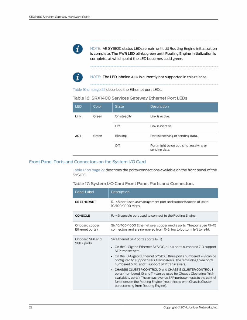
NOTE: All SYSIOC status LEDs remain unlit till Routing Engine initializationis complete. The PWR LED blinks green until Routing Engine initialization is
complete, at which point the LED becomes solid green.
NOTE: The LED labeled AED is currently not supported in this release.
Table 16 on page 22 describes the Ethernet port LEDs.
Table 16: SRX1400 Services Gateway Ethernet Port LEDs
DescriptionStateColorLED
Link is active.On steadilyGreenLink
Link is inactive.Off
Port is receiving or sending data.BlinkingGreenACT
Port might be on but is not receiving orsending data.
Off
Front Panel Ports and Connectors on the System I/O Card
Table 17 on page 22 describes the ports/connections available on the front panel of the
SYSIOC.
Table 17: System I/O Card Front Panel Ports and Connectors
DescriptionPanel Label
RJ-45 port used as management port and supports speed of up to10/100/1000 Mbps.
RE ETHERNET
RJ-45 console port used to connect to the Routing Engine.CONSOLE
Six 10/100/1000 Ethernet over copper media ports. The ports use RJ-45connectors and are numbered from 0-5, top to bottom, left to right.
Onboard copperEthernet ports)
Six Ethernet SFP ports (ports 6-11).
• On the 1-Gigabit Ethernet SYSIOC, all six ports numbered 7-9 supportSFP transceivers.
• On the 10-Gigabit Ethernet SYSIOC, three ports numbered 7-9 can beconfigured to support SFP+ transceivers. The remaining three portsnumbered 6, 10, and 11 support SFP transceivers.
• CHASSIS CLUSTER CONTROL 0 and CHASSIS CLUSTER CONTROL 1ports (numbered 10 and 11) can be used for Chassis Clustering (highavailability ports). These two revenue SFP ports connects to the controlfunctions on the Routing Engine (multiplexed with Chassis Clusterports coming from Routing Engine).
Onboard SFP andSFP+ ports
Copyright © 2014, Juniper Networks, Inc.22
SRX1400 Services Gateway Hardware Guide

NOTE: We strongly recommend the use of Juniper Networks SFP and SFP+transceivers.We cannot guarantee correct operation if other transceivers areused.The transceiver typecanbedifferent ineachport, as longasasupportedpart number is used.
RelatedDocumentation
Overview of the SRX1400 Services Gateway CFMs on page 12•
• SRX1400 Services Gateway Hardware Components on page 14
• Troubleshooting the System I/O Card on the SRX1400 Services Gateway on page 109
• Replacing the SYSIOC on the SRX1400 Services Gateway on page 133
SRX1400 Services Gateway NSPC
The Network and Services Processing Card (NSPC) is a double-wide common form-factor
module (CFM) card that provides the processing power to run integrated services such
as firewall, IP Security (IPsec), and intrusion detection and prevention (IDP). The NSPC
contains a Services Processing Unit (SPU) and a Network Processing Unit (NPU). All
traffic traversing the services gateway is passed to the NSPC to have services processing
applied to it. Traffic is intelligently distributed for services processing, including session
setup based on policies, fast packet processing for packets that match a session,
encryption and decryption, and Internet Key Exchange (IKE) negotiation.
NOTE:
• If theNSPC is notpresent, youmust install a filler cover to shield theemptyslots 1 and3and tokeepcontaminantsoutof thechassis andallowcoolingair to circulate properly through the device. The services gateway isdelivered with a filler cover already installed over these slots.
• The services gateway requires at least one SPU and one NPU in the slotslabeled 1 and3 in order to operate. You can install anNSPC,which containsan NPU and an SPU, or you can install a combination of SRX3000 SeriesServices Gateway NPC and SPC, on the SRX1400 Services Gateway. Youmust use a double-wide tray with the combination of NPC and SPC.
• TheONLINE button on the NSPC does not perform any function and is
currently not supported.
• You can use a single-wide Network Processing Card (NPC) and asingle-wideServicesProcessingCard (SPC)asanalternative to theNSPC.
Figure 10 on page 24 shows the SRX1400 Services Gateway NSPC.
23Copyright © 2014, Juniper Networks, Inc.
Chapter 2: SRX1400 Services Gateway Hardware Components

Figure 10: SRX1400 Services Gateway Network and Services ProcessingCard
g033
504
Table 18 on page 24 describes the NSPC behavior indicated by the LEDs on its front panel.
Table 18: SRX1400 Services Gateway Network and Services ProcessingCard LED Indicators
DescriptionStatusColorLabel
The NSPC is running under acceptable load.On steadilyGreenSERVICE
The NSPC is overloaded.On steadilyAmber
No service is being provided by the NSPC.On steadilyRed
The NSPC is not enabled.OffUnlit
The NSPC is operating normally.On steadilyGreenOK/FAIL
The NSPC is preparing for a hot-swappableevent.
BlinkingGreen
The NSPC has failed and is not operatingnormally.
On steadilyRed
The NSPC is powered down.OffUnlit
RelatedDocumentation
Overview of the SRX1400 Services Gateway CFMs on page 12•
• SRX1400 Services Gateway Hardware Components on page 14
• Troubleshooting the Network and Services Processing Card on the SRX1400 Services
Gateway on page 110
• Replacing a Network and Services Processing Card on the SRX1400 Services Gateway
on page 125
SPCs for the SRX1400 Services Gateway
Services Processing Cards (SPCs) are common form-factor module (CFM) cards that
provide processing power to run integrated services such as firewall, IPsec, and IDP. All
traffic traversing the services gateway is passed to an SPC to have services processing
applied to it. Traffic is intelligently distributed by Network Processing Cards (NPCs) to
Copyright © 2014, Juniper Networks, Inc.24
SRX1400 Services Gateway Hardware Guide

SPCs for services processing, including session setup based on policies, fast packet
processing for packets that match a session, encryption and decryption, and IKE
negotiation.
There are two places where you can install an SPC in your SRX1400 Services Gateway:
• You can install an SPC in the front-panel slot labeled 1 if you also install an NPC in the
slot labeled 3. This combination of SPC and NPC replaces the full-width Network and
Services Processing (NSPC) card that is normally installed in the SRX1400 Services
Gateway to perform both services processing and network processing functions.
• If your SRX1400 Services Gateway is running Junos OS Release 12.1X44-D10 or later,
you can install an SPC in the slot labeled 2. Doing so increases the services processing
performance of the services gateway and increases its session capacity.
NOTE:
• If a CFM slot is not occupied by a card, youmust install a blank panel toshield the empty slot and to allow cooling air to circulate properly throughthe device.
Figure 11 on page 25 shows an SPC that can be used on an SRX1400 Services Gateway.
Figure 11: Services Processing Card
g036
032
SRX3K-SPC-1-10-40
For detailed information about the SPCs supported by the services gateway, see the
SRX1400, SRX3400, and SRX3600 Services Gateway Module Guide at
www.juniper.net/techpubs/.
RelatedDocumentation
Installing an SPC in an SRX1400 Services Gateway on page 61•
• Troubleshooting Services Processing Cards on the SRX1400 Services Gateway on
page 111
• Replacing an SPC on the SRX1400 Services Gateway on page 128
25Copyright © 2014, Juniper Networks, Inc.
Chapter 2: SRX1400 Services Gateway Hardware Components

NPCs for the SRX1400 Services Gateway
NOTE: The SRX1400 Services Gateway is not normally equipped with aNetworkProcessingCard (NPC). Inmost configurations, network processingfunctions are performed by the Network and Services Processing Card(NSPC). However, you can install an NPC in the front-panel slot labeled 3 if
you also install a Services Processing Card (SPC) in the slot labeled 1. This
combination of SPC and NPC replaces the full-width NSPC that is normallyinstalled in the SRX1400 Services Gateway to perform both servicesprocessing and network processing functions.
NPCs are common form-factor module (CFM) cards that receive inbound traffic from
the I/O cards (IOCs) and direct it to the appropriate SPC for services processing. Once
services processing is complete, the NPC receives outbound traffic from the SPC(s) and
directs it back to the appropriate IOC or SYSIOC. Additionally, the NPC performs the
following functions:
• Buffers incoming traffic and queues outgoing traffic.
• Performs advanced traffic management, including denial of service/distributed denial
of service (DoS/DDoS) protective measures. For example, it can drop traffic to or from
a particular IP address, protecting the device from Internet Control Message Protocol
(ICMP), UDP, and TCP SYN flooding, and buffering bursty traffic to protect the SPC.
NOTE:
• If a CFM slot is not occupied by a card, youmust install a blank panel toshield the empty slot and to allow cooling air to circulate properly throughthe device.
• TheONLINE button on the NPC does not perform any function and is
currently not supported.
Figure 12 on page 26 shows the NPC that can be used on SRX1400 Services Gateway.
Figure 12: Network Processing Card
g036
033
SRX3K-NPC
For detailed information about the NPCs supported by the services gateway, see the
SRX1400, SRX3400, and SRX3600 Services Gateway Module Guide at
www.juniper.net/techpubs/.
Copyright © 2014, Juniper Networks, Inc.26
SRX1400 Services Gateway Hardware Guide

RelatedDocumentation
Installing an NPC in an SRX1400 Services Gateway on page 63•
• Replacing a Network Processing Card on the SRX1400 Services Gateway on page 127
• Troubleshooting an NPC on the SRX1400 Services Gateway on page 112
SRX1400 Services Gateway Routing Engine
The Routing Engine is a PowerPC platform that runs Junos operating system (Junos OS).
Software processes that run on the Routing Engine maintain the routing tables, manage
the routing protocols used on the device, control the device interfaces, control some
chassis components, and provide the interface for system management and user access
to the device.
A pair of USB ports on the Routing Engine accept USB memory cards that allow you to
load Junos OS and perform file transfers.
Figure 13 on page 27 shows the SRX1400 Services Gateway Routing Engine.
Figure 13: SRX1400 Services Gateway Routing Engine
g033
507
The Routing Engine also provides the following integrated services:
• Central Packet Forwarding Engine Processing (CPP)—This service manages all common
form-factor modules (CFM) cards.
• System Control—This service provides system management functions such as
monitoring of fan tray, and power systems.
NOTE: TheSRX1400ServicesGatewaymusthaveaRoutingEngine installedin slot RE. The SYSIOC port labeled RE ETHERNET connects directly to the
RE Routing Engine slot.
Figure 14 on page 28 shows the SRX1400 Services Gateway Routing Engine.
27Copyright © 2014, Juniper Networks, Inc.
Chapter 2: SRX1400 Services Gateway Hardware Components

Figure 14: SRX1400 Services Gateway Routing Engine
g033
556
For detailed information about the Routing Engines supported by the services gateway,
see the SRX1400, SRX3400, and SRX3600 Services Gateway Module Guide at
www.juniper.net/techpubs/.
RelatedDocumentation
Overview of the SRX1400 Services Gateway CFMs on page 12•
• SRX1400 Services Gateway Hardware Components on page 14
• Maintaining the Routing Engine on the SRX1400 Services Gateway on page 100
• Replacing a Routing Engine on the SRX1400 Services Gateway on page 122
IOCs and NP-IOCs Supported on the SRX1400 Services Gateway
I/O cards (IOCs) are common form-factor module (CFM) cards that provide additional
physical network connections to the services gateway. Their primary function is to deliver
data packets arriving on the physical ports to the Network and Services Processing Card
(NSPC) and to forward data packets out the physical ports after services processing.
Network Processing I/O cards are IOCs that have their own Network Processing Units
(NPUs) so that traffic traversing the NP-IOC does not have to traverse the services
gateway bus to a remote NPC. They are well suited to low-latency applications.
You can install one IOC or NP-IOC in the CFM 2 of the SRX1400 Services Gateway. If no
CFM card is installed in slot 2, you must install a blank panel to shield the empty slot and
to allow cooling air to circulate properly through the services gateway.
For detailed information about the IOCs and NP-IOCs supported by the services gateway,
see the SRX1400, SRX3400, and SRX3600 Services Gateway Module Guide at
www.juniper.net/techpubs/.
NOTE: IOCs are not providedwith theSRX1400ServicesGateway. Youmustorder them separately. Contact your Juniper Networks customer servicerepresentative for more information.
Copyright © 2014, Juniper Networks, Inc.28
SRX1400 Services Gateway Hardware Guide

RelatedDocumentation
Installing an IOC or NP-IOC in an SRX1400 Services Gateway on page 65•
SRX1400 Services Gateway Power Supplies
This topic includes the following sections:
• SRX1400 Services Gateway Power Supplies Overview on page 29
• SRX1400 Services Gateway AC Power Supply on page 30
• SRX1400 Services Gateway DC Power Supply on page 31
SRX1400 Services Gateway Power Supplies Overview
The SRX1400 Services Gateway uses following power supplies:
• AC Power Supply (for SRX1400BASE-GE-AC and SRX1400BASE-XGE-AC models)
For details, see “SRX1400 Services Gateway AC Power Supply” on page 30.
• DC Power Supply (for SRX1400BASE-GE-DC and SRX1400BASE-XGE-DC models)
For details, see “SRX1400 Services Gateway DC Power Supply” on page 31.
The power supplies are located at the front of the chassis. Each AC power supply weighs
approximately 3.1 lb (1.4 kg). Each DC power supply weighs approximately 2.9 lb (1.3 kg).
NOTE: Only redundant power supplies (AC or DC) support hot-swappablefunctionality.
The SRX1400 Services Gateway uses either one AC or one DC power supply unit. A second
AC or DC power supply can be used with its matching type of power supply to offer
redundancy. The power supplies connect to the backplane, which distributes 10 V main
power and 3.3 V standby power to the services gateway components. Each power supply
is cooled by its own internal cooling system.
CAUTION: Do notmix AC and DC power supplies within the same servicesgateway. Damage to the devicemight occur.
RelatedDocumentation
SRX1400 Services Gateway AC Power Supply on page 30•
• SRX1400 Services Gateway DC Power Supply on page 31
29Copyright © 2014, Juniper Networks, Inc.
Chapter 2: SRX1400 Services Gateway Hardware Components

SRX1400 Services Gateway AC Power Supply
This topic includes the following sections:
• AC Power Supply Overview on page 30
• AC Power Supply Electrical Specifications on page 30
• AC Power Supply LEDs on page 31
AC Power Supply Overview
In an AC power configuration, the SRX1400 Services Gateway contains one or two AC
power supplies, located at the front panel of the chassis in slots PEM0 and PEM1. Each
power supply provides power to all components in the services gateway. When two
power supplies are present, they share power almost equally within a fully populated
system. The two AC power supplies provide full power redundancy. If one power supply
fails or is removed, the remaining power supply redistributes the electrical load without
interruption.
Figure 15 on page 30 shows the SRX1400 Services Gateway AC power supply.
NOTE: Onlya redundantpowersupplysupportshot-swappable functionality.
Figure 15: SRX1400 Services Gateway AC Power Supply
g033
508
AC Power Supply Electrical Specifications
Table 19 on page 30 lists the AC power supply electrical specifications.
Table 19: AC Power Supply Electrical Specifications
SpecificationParameter
1000 WMaximum output power
100-127 V / 200-240 VAC input voltage
50 / 60 HzAC input line frequency
13.0 A (Max.) at 100 VACAC input current rating
Copyright © 2014, Juniper Networks, Inc.30
SRX1400 Services Gateway Hardware Guide

AC Power Supply LEDs
Each AC power supply faceplate displays a single LED to indicate the status of the power
supply (see Table 20 on page 31).
Table 20: AC Power Supply LEDs
Condition IndicatedStatusColor
AC input voltage is present, and both main 12 V output and standby3.3 V output are enabled and healthy.
On steadilyGreen
AC input voltage is present, standby 3.3 V output is on, but the main12 V output is disabled. This condition usually indicates that the devicehas been powered off at the POWER button on the SYSIOC front panel.This condition can also indicate that either the SYSIOC or RoutingEngine has been removed from the services gateway.
Blinking
The power supply has detected one or more of the following faults:
• Power supply fan failure
• Power supply over-temperature condition
• Over-current or under-voltage condition on the standby 3.3 V output
On steadilyAmber
The power supply has detected one or more of the following faults:
• Under-voltage condition on the 12 V output
• Over-voltage condition on the 12 V output
• Over-current condition on the 12 V output
Blinking
RelatedDocumentation
SRX1400 Services Gateway Power Supplies Overview on page 29•
• Installing an AC Power Supply in the SRX1400 Services Gateway on page 68
• Maintaining Power Supplies on the SRX1400 Services Gateway on page 101
• Troubleshooting the Power System on the SRX1400 Services Gateway on page 112
SRX1400 Services Gateway DC Power Supply
This topic includes the following sections:
• DC Power Supply Overview on page 31
• DC Power Supply Electrical Specifications on page 32
• DC Power Supply LEDs on page 32
DC Power Supply Overview
In a DC power configuration, the SRX1400 Services Gateway contains one or two DC
power supplies, located at the front of the chassis in slots P0 and P1. Each power supply
provides power to all components in the services gateway. When two power supplies
are present, they share power almost equally within a fully populated system. The two
31Copyright © 2014, Juniper Networks, Inc.
Chapter 2: SRX1400 Services Gateway Hardware Components

DC power supplies provide power redundancy. If one power supply fails or is removed,
the remaining power supply redistributes the electrical load without interruption.
NOTE: Only redundant power supply supports hot-swappable functionality.
DC Power Supply Electrical Specifications
Each DC power supply has a single DC input (-48 VDC and return) that requires a
dedicated 40 A (-48 VDC) circuit breaker. Table 21 on page 32 lists the DC power supply
electrical specifications.
Table 21: DC Power Supply Electrical Specifications
SpecificationParameter
1200 WMaximum output power
–40 to –72 VDCDC input voltage
30 A @ -48 VDCDC input current rating
DC Power Supply LEDs
Each DC power supply faceplate displays a single LED to indicate the status of the power
supply (see Table 22 on page 32).
Table 22: DC Power Supply LED
Indicated ConditionLED StatusColor
DC input voltage is present, and both main 12 V output and standby3.3 V output are enabled and healthy.
On steadilyGreen
DC input voltage is present, standby 3.3 V output is on, but the main12 V output is disabled. This condition usually indicates that the devicehas been powered off at the POWER button on the SYSIOC front panel.This condition can also indicate that either the SYSIOC or RoutingEngine has been removed from the services gateway.
Blinking
The power supply has detected one or more of the following faults:
• Power supply fan failure
• Power supply over-temperature condition
• Over-current or under-voltage condition on the standby 3.3V output
On steadilyRed
The power supply has detected one or more of the following faults:
• Under-voltage condition on the 12 V output
• Over-voltage condition on the 12 V output
• Over-current condition on the 12 V output
Blinking
Copyright © 2014, Juniper Networks, Inc.32
SRX1400 Services Gateway Hardware Guide

RelatedDocumentation
SRX1400 Services Gateway Power Supplies Overview on page 29•
• Installing a DC Power Supply in the SRX1400 Services Gateway on page 69
• Maintaining Power Supplies on the SRX1400 Services Gateway on page 101
• Troubleshooting the Power System on the SRX1400 Services Gateway on page 112
SRX1400 Services Gateway Cooling System
The cooling system consists of a fan tray containing two fans. These fans keep all services
gateway components within the acceptable temperature range.
The SRX1400 Services Gateway also includes an air filter that protects the device from
dust entering into the system.
The SRX1400 Services Gateway has one fan tray located in the side of the chassis and
can be plugged in from the rear of the chassis.
From the front of the chassis, there is a single air intake on the left side of the services
gateway. Air is pushed from the fan tray through the air filter and then to the card cage.
The air is exhausted out the right of the system.
Figure 16 on page 33 SRX1400 Services Gateway fan tray.
Figure 16: SRX1400 Services Gateway Fan Tray
g033
563
The Routing Engine monitors the temperature of the device components. Above an
ambient temperature of 30° C to 35° C, the fans operate at full speed. Below 30° C, the
fans operate at a reduced speed. If a fan fails or the ambient temperature rises above a
threshold, the speed of the other fan is automatically adjusted to keep the temperature
within the acceptable range. If the ambient maximum temperature specification is
exceeded and the system cannot be adequately cooled, the Routing Engine shuts down
the system by disabling output power from each power supply.
The fan tray includes a single LED, which can be used to monitor the fan speed. The fan
tray LED indications can be used to detect the condition when the fan-speed has reduced
to a safer value, so that fan tray can be removed from the device safely. This LED is
33Copyright © 2014, Juniper Networks, Inc.
Chapter 2: SRX1400 Services Gateway Hardware Components

controlled by the Routing Engine. The fan tray LED is located on the fan tray, which is
visible only when the fan tray door is opened.
The fan-tray faceplate has a single LED to indicate the status of the fans and fan tray
(see Table 23 on page 34).
Table 23: Fan Tray LED
Indicated ConditionLED StatusColor
Fans are running and fan tray is functioning normally. Do not removethe fan tray in this condition.
OffAmber
Fans are not running, and fan tray can be removed safely.
NOTE: This Fan tray LED lights only when fans are shutdown manuallyusing the CLI FAN . The message FAN confirms that fans are stoppedcompletely.
The Fan Tray LED does not indicate fan failure. The FAN LED availableon the System I/O card indicates the fan failure status.
On Steadily
NOTE: The fan tray LED provides additional safety measures. Even thoughyou can remove the fan tray while the fans are still running, we stronglyrecommend that you wait until the fan tray LED lights steadily amber(indicating that the fans are not running) before you remove the fan tray.
NOTE: The fan tray supports hot-swappable functionality. We recommendyou to reinstall the fan tray within threeminutes; otherwise, the servicesgateway temperaturemight exceed themaximum recommended roomtemperature and the device shuts down automatically in four minutes.
RelatedDocumentation
• Troubleshooting the Cooling System on the SRX1400 Services Gateway on page 107
• Routine Maintenance Procedures for the SRX1400 Services Gateway on page 98
• Maintaining the Fan Tray on the SRX1400 Services Gateway on page 99
• Maintaining the Air Filter on the SRX1400 Services Gateway on page 98
Copyright © 2014, Juniper Networks, Inc.34
SRX1400 Services Gateway Hardware Guide

PART 2
Setting Up the SRX1400 ServicesGateway
• Preparing the Site for SRX1400 Services Gateway Installation on page 37
• Unpacking the SRX1400 Services Gateway on page 43
• Installing the SRX1400 Services Gateway on page 47
• Installing Additional Components into the SRX1400 Services Gateway on page 59
• Connecting the SRX1400 Services Gateway on page 71
• Grounding and Providing Power to the SRX1400 Services Gateway on page 75
• Performing Initial Software Configuration on the SRX1400 Services Gateway on page 85
35Copyright © 2014, Juniper Networks, Inc.

Copyright © 2014, Juniper Networks, Inc.36
SRX1400 Services Gateway Hardware Guide

CHAPTER 3
Preparing the Site for SRX1400 ServicesGateway Installation
This chapter includes the following topics:
• Site Preparation Checklist for the SRX1400 Services Gateway on page 37
• SRX1400 Services Gateway Rack, Cabinet, and Airflow Clearance
Requirements on page 38
Site Preparation Checklist for the SRX1400 Services Gateway
The checklist in Table 24 on page 37 summarizes the tasks you need to perform when
preparing a site for SRX1400 Services Gateway installation.
Table 24: Site Preparation Checklist
DatePerformedByFor More Information ...Item or Task
“SRX1400 Services GatewayEnvironmental Specifications” on page 7
Verify that environmentalfactors such as temperatureand humidity do not exceedservices gateway tolerances.
“SRX1400 Services Gateway RackRequirements” on page 40
Select the type of rack orcabinet.
“Clearance Requirements for Airflow andHardware Maintenance of the SRX1400Services Gateway” on page 42
Plan rack or cabinet location,including required spaceclearances.
“SRX1400 Services Gateway RackRequirements” on page 40
If a rack is used, secure rackto floor and buildingstructure.
37Copyright © 2014, Juniper Networks, Inc.

Table 24: Site Preparation Checklist (continued)
DatePerformedByFor More Information ...Item or Task
“Console Port Cable and WireSpecifications for the SRX1400 ServicesGateway” on page 204
“SRX1400 Services Gateway AC PowerCord Specifications” on page 195
“SRX1400 Services Gateway DC PowerCable Specifications” on page 191
Acquire cables andconnectors.
“SRX1400 Services Gateway GroundingCable Specification” on page 187“SignalLoss in Multimode and Single-ModeFiber-Optic Cable for the SRX1400Services Gateway” on page 200
Locate sites for connectionof system grounding.
“SRX1400 Services Gateway ElectricalWiring Guidelines” on page 199
Measure distance betweenexternal power sources andservices gateway installationsite.
“Calculating the Power Budget forFiber-Optic Cable for the SRX1400Services Gateway” on page 202
“Calculating the Power Margin forFiber-Optic Cable for the SRX1400Services Gateway” on page 202
Calculate the optical powerbudget and optical powermargin.
RelatedDocumentation
Installation Overview for the SRX1400 Services Gateway on page 47•
• Clearance Requirements for Airflow and Hardware Maintenance of the SRX1400
Services Gateway on page 42
• SRX1400 Services Gateway Cabinet Requirements on page 39
• SRX1400 Services Gateway Rack Requirements on page 40
SRX1400 Services Gateway Rack, Cabinet, and Airflow Clearance Requirements
The services gateway can be installed in a standard 19 in. (482 mm) or larger enclosed
cabinet. The cabinet requirements are described in the following topics:
• SRX1400 Services Gateway Cabinet Requirements on page 39
• SRX1400 Services Gateway Rack Requirements on page 40
• Clearance Requirements for Airflow and Hardware Maintenance of the SRX1400
Services Gateway on page 42
Copyright © 2014, Juniper Networks, Inc.38
SRX1400 Services Gateway Hardware Guide

SRX1400 Services Gateway Cabinet Requirements
This topic includes the following sections:
• Cabinet Size and Clearance Requirements on page 39
• Cabinet Airflow Requirements on page 39
Cabinet Size and Clearance Requirements
The minimum size cabinet that can accommodate the services gateway is 27.5 in.
(69.8 cm) wide and 31.5 in. (80.0 cm) deep. The cabinet must allow at least 5 in. (13
cm) of clearance on each side of the chassis to allow for cooling air to flow through the
vents on each side of the device. A cabinet larger than the minimum requirement provides
better airflow and reduces the chance of overheating.
Allow at least 3 in. (7.6 cm) of vertical clearance between the top and bottom of the
services gateway and other devices in the cabinet.
If you provide adequate cooling air and airflow clearance, you can stack eight devices in
a cabinet that has at least 40 U (70 in. or 1.78 m) of usable vertical space.
Cabinet Airflow Requirements
When you mount the services gateway in a cabinet, you must ensure that ventilation
through the cabinet is sufficient to prevent overheating. Consider the following
requirements when planning for chassis cooling:
• Ensure that the cool air supply you provide through the cabinet can adequately dissipate
the thermal output of the services gateway.
• Allow at least 3 in. (7.6 cm) of vertical clearance between the top and bottom of the
services gateway and other devices in the cabinet.
• Ensure that the cabinet allows the chassis hot exhaust air to exit from the cabinet
without recirculating into the services gateway. An open cabinet (without a top or
doors) that employs hot air exhaust extraction from the top allows the best airflow
through the chassis.
• Ensure that the cabinet provides at least 13 cm (5 in) of clearance on each side of the
chassis for cooling airflow.
• If the cabinet contains a top or doors, you must provide perforations in these elements
to allow adequate airflow through the cabinet to dissipate the heat generated by all
of the devices in the cabinet.
• Route and dress all cables to minimize the blockage of airflow to and from the chassis.
RelatedDocumentation
Installation Overview for the SRX1400 Services Gateway on page 47•
• Site Preparation Checklist for the SRX1400 Services Gateway on page 37
• SRX1400 Services Gateway Rack Requirements on page 40
• Clearance Requirements for Airflow and Hardware Maintenance of the SRX1400
Services Gateway on page 42
39Copyright © 2014, Juniper Networks, Inc.
Chapter 3: Preparing the Site for SRX1400 Services Gateway Installation

SRX1400 Services Gateway Rack Requirements
This topic includes the following sections:
• SRX1400 Services Gateway Rack Size and Strength Requirements on page 40
• SRX1400 Services Gateway Spacing of Mounting Bracket Holes on page 41
• Connecting the SRX1400 Services Gateway to the Building Structure on page 41
SRX1400 Services Gateway Rack Size and Strength Requirements
The SRX1400 Services Gateway can be installed in a rack. Many types of racks are
acceptable, including four-post (telco) racks and open-frame racks.
You can front-mount or rear-mount the services gateway in a two-post rack, a four-post
rack, or a cabinet.
NOTE: Though two-post front mounting is most commonmethod ofinstallation for theSRX1400device, you can also front-mount or rear-mountthe chassis in a four-post rack. However, there is no support shelf providedfor the rear edge of the chassis to rest.
The device is designed for installation into a 19-in. (48.26 cm) rack as defined in Cabinets,
Racks, Panels, and Associated Equipment (document number EIA-310–D) published by
the electronics Industry Association (http://www.eia.org).
With the use of adapters, the device is designed to fit into a 600-mm-wide (23.62-mm)
rack or cabinet, as defined in the four-part Equipment Engineering (EE); European
telecommunications standard for equipment practice (document numbers ETS 300
119-1 through 119-4) published by the European Telecommunications Standards Institute
(http://www.etsi.org). Use approved wing devices to narrow the opening between the
rails.
The rack rails must be spaced widely enough to accommodate the device chassis's
external dimensions: 5.25 in. (13.3 cm) high, 13.8 in. (35.05 cm) deep, and 17.5 in. (44.5
cm) wide. The spacing of rails and adjacent racks must also allow for the clearances
around the device and rack.
The chassis height of 5.25 in. (13.3 cm) is approximately 3 U. A U is the standard rack unit
defined in Cabinets, Racks, Panels, and Associated Equipment (document number
EIA-310-D) published by the Electronics Industry Association. You can stack eight
SRX1400 Services Gateways in a rack that has at least 40 U (70 in. or 1.78 m) of usable
vertical space.
The rack must be strong enough to support the weight of the fully configured device, up
to 42.3 lb (19.3 kg). If you stack 8 fully configured devices in one rack, it must be capable
of supporting up to 341 lb (155 kg)
Copyright © 2014, Juniper Networks, Inc.40
SRX1400 Services Gateway Hardware Guide

Figure 17: Typical Open-Frame Rack
SRX1400 Services Gateway Spacing of Mounting Bracket Holes
The device can be mounted in any rack that provides holes or hole patterns spaced at
1 U (1.75 in. or 4.4 cm) increments. The mounting brackets used to attach the chassis to
a rack are designed to fasten to holes spaced at those distances.
Connecting the SRX1400 Services Gateway to the Building Structure
Always secure the rack to the structure of the building. If your geographical area is subject
to earthquakes, bolt the rack to the floor. For maximum stability, also secure the rack to
ceiling brackets. For more information, see “Rack-Mounting Requirements and Warnings”
on page 157.
RelatedDocumentation
Installation Overview for the SRX1400 Services Gateway on page 47•
• Site Preparation Checklist for the SRX1400 Services Gateway on page 37
• SRX1400 Services Gateway Cabinet Requirements on page 39
• Clearance Requirements for Airflow and Hardware Maintenance of the SRX1400
Services Gateway on page 42
41Copyright © 2014, Juniper Networks, Inc.
Chapter 3: Preparing the Site for SRX1400 Services Gateway Installation

Clearance Requirements for Airflow and HardwareMaintenance of the SRX1400 ServicesGateway
When planning the installation site, you need to allow sufficient clearance around the
rack (see Figure 18 on page 42):
Figure 18: SRX1400 Services Gateway Clearance Requirements
g033
510
39.44 cm
Front: 76.2 cm clearance required for maintenance
44.45 cm
Minimum13 cm between
chassis and wallor non-heat-producingsurface;Minimum15.2 cmbetweendevices
Sides:
Rear: 61 cm clearance requiredfor maintenance
• For the cooling system to function properly, the airflow around the chassis must be
unrestricted. Allow at least 6 in. (15.2 cm) of clearance between devices. Allow 5 in.
(13 cm) between the side of the chassis and any non-heat-producing surface such as
a wall.
• For service personnel to remove and install hardware components, there must be
adequate space at the front and back of the services gateway. At least 24 in. (61 cm)
is required both in front of and behind the device. NEBS GR-63 recommends that you
allow at least 30 in. (72.6 cm) in front of the rack and 24 in. (61.0 cm) behind the rack.
RelatedDocumentation
• Installation Overview for the SRX1400 Services Gateway on page 47
• Site Preparation Checklist for the SRX1400 Services Gateway on page 37
• SRX1400 Services Gateway Cabinet Requirements on page 39
• SRX1400 Services Gateway Rack Requirements on page 40
Copyright © 2014, Juniper Networks, Inc.42
SRX1400 Services Gateway Hardware Guide

CHAPTER 4
Unpacking the SRX1400 ServicesGateway
This chapter includes the following topics:
• Required Tools and Parts for Unpacking the SRX1400 Services Gateway on page 43
• Unpacking the SRX1400 Services Gateway on page 43
• Verifying Parts Received with the SRX1400 Services Gateway on page 45
Required Tools and Parts for Unpacking the SRX1400 Services Gateway
To unpack the SRX1400 Services Gateway and prepare for installation, you need a Phillips
(+) screwdriver, number 2.
RelatedDocumentation
Installation Overview for the SRX1400 Services Gateway on page 47•
• Site Preparation Checklist for the SRX1400 Services Gateway on page 37
• Unpacking the SRX1400 Services Gateway on page 43
• Verifying Parts Received with the SRX1400 Services Gateway on page 45
Unpacking the SRX1400 Services Gateway
The SRX1400 Services Gateway is shipped in a cardboard carton. Getting Started
installation instructions and an accessory box are also included in the shipping carton.
NOTE: The services gateway is maximally protected inside the shippingcarton. Do not unpack it until you are ready to begin installation.
Figure 19 on page 44 shows the SRX1400 Services Gateway in a shipping carton.
To unpack the services gateway:
1. Move the shipping carton to a staging area as close to the installation site as possible,
where you have enough room to remove the components from the chassis.
2. Position the shipping carton with the arrows pointing up.
43Copyright © 2014, Juniper Networks, Inc.

3. Remove the plastic handle inserts and lift the cardboard cover off the device.
4. Remove the foam covering the top of the services gateway.
5. Remove the accessory box and the SRX1400 Services Gateway Getting Started Guide.
Figure 19: Unpack the SRX1400 Services Gateway
g033
512
6. With a person on each side of the carton, carefully lift the services gateway from the
carton and place it on a flat, level surface. Remove the bag covering the services
gateway.
7. Verify the parts received against the list provided in the “Verifying Parts Received with
the SRX1400 Services Gateway” on page 45.
8. Save the carton and the packing materials in case you need to move or ship the services
gateway at a later time.
NOTE: At the timeofshipment, theadjacentCFMslots 1and3arecoveredwith a filler cover and slot 2 is covered with a blank panel. Save the fillercover and the blank panel after removing them from the slots, in case youneed themwhen you pack or move the chassis at a later time. The fillercover is baremetal, without a colored overlay.
9. Proceed to install the services gateway.
RelatedDocumentation
Installation Overview for the SRX1400 Services Gateway on page 47•
• Site Preparation Checklist for the SRX1400 Services Gateway on page 37
• Required Tools and Parts for Unpacking the SRX1400 Services Gateway on page 43
Copyright © 2014, Juniper Networks, Inc.44
SRX1400 Services Gateway Hardware Guide

• Verifying Parts Received with the SRX1400 Services Gateway on page 45
Verifying Parts Receivedwith the SRX1400 Services Gateway
A packing list is included in each shipment. Check the parts in the shipment against the
items on the packing list. The packing list specifies the part numbers and descriptions of
each part in your order. Note that feature and service cards are shipped in separate boxes
from the chassis.
If any part is missing, contact a customer service representative.
A fully configured services gateway contains the chassis with installed components,
listed in Table 25 on page 45, and an accessory box, which contains the parts listed in
Table 26 on page 46. The parts shipped with your services gateway can vary depending
on the configuration you ordered.
Table 25: Parts List for a Fully Configured SRX1400 Services Gateway
QuantityComponent
1Chassis, including backplane, and rack-mountingbrackets
1NSPC
1Routing Engine
1System I/O card
At least 1 and up to 2Power supplies
1Fan tray
1Air filter
1SRX1400 Services Gateway Getting Started Guide
• 1 single-wide blank panel for CFM slot2.
• 1 double-wide blank panel foradjacent CFM slots 1 and 3.
Blank panels for slots without components installed
1AC Power Cord
NOTE: The NSPC is not a part of the base chassis configuration. Youmustorder it separately. Contact your Juniper Networks customer servicerepresentative for more information.
45Copyright © 2014, Juniper Networks, Inc.
Chapter 4: Unpacking the SRX1400 Services Gateway

NOTE: If you are planning to use an Network Processing Card (NPC) and aServices Processing Card (SPC) (supported on SRX3000 Series ServicesGateway) on the SRX1400 device, then youmust order them separately.
YoucanuseanNPCandanSPCon theSRX1400device inplaceof theNSPC.
To install the NPC and SPC on the SRX1400 Services Gateway, youmustorder the double-wide tray (SRX1K3K-2CFM-TRAY) to hold two single-wideCFMs (NPC and SPC) separately. Contact your Juniper Networks customerservice representative for more information.
Table 26: Accessory Box Parts List
QuantityPart
1Rack mount kit
1RJ-45-to-DB-9 cable to connect the services gateway through the serial port
1Juniper Networks Product Warranty
1End User License Agreement
1SRX1400 Services Gateway Getting Started Guide
1Documentation Information Card
1Product Registration
1Juniper Compliance Form Letter; Reduction of Hazardous Substances (RoHS)
1Document sleeve
1ESD wrist strap with cable
RelatedDocumentation
• Installation Overview for the SRX1400 Services Gateway on page 47
• Site Preparation Checklist for the SRX1400 Services Gateway on page 37
• Required Tools and Parts for Unpacking the SRX1400 Services Gateway on page 43
• Unpacking the SRX1400 Services Gateway on page 43
Copyright © 2014, Juniper Networks, Inc.46
SRX1400 Services Gateway Hardware Guide

CHAPTER 5
Installing the SRX1400 Services Gateway
This chapter includes the following topics:
• Installation Overview for the SRX1400 Services Gateway on page 47
• SRX1400 Services Gateway Safety Requirements, Warnings, and Guidelines on page 48
• Required Tools for Installing the SRX1400 Services Gateway on page 49
• Preparing the SRX1400 Services Gateway for Rack-Mount or Cabinet
Installation on page 49
• Installing the Mounting Hardware for the SRX1400 Services Gateway on page 50
• Installing the SRX1400 Services Gateway in a Rack or Cabinet Using a Mechanical
Lift on page 50
• Installing the SRX1400 Services Gateway in a Rack or Cabinet Manually (Without a
Mechanical Lift) on page 53
Installation Overview for the SRX1400 Services Gateway
This section provides instructions for installing the SRX1400 Services Gateway in a rack
or cabinet. Because of the size and weight of the device—up to 42.5 lb (19.3 kg) (fully
loaded chassis) depending on the configuration—we recommend that you install it using
a mechanical lift. The SRX1400 Services Gateway is rack-mountable with support for
both front-mounting and rear-mounting.
After you have prepared your installation site, you are ready to unpack and install the
services gateway. It is important to proceed through the installation process as shown
in Table 27 on page 47.
Table 27: SRX1400 Services Gateway Installation Process
For More Information, See:Procedures
“Site Preparation Checklist for the SRX1400 Services Gateway”on page 37
Review the safety guidelines
47Copyright © 2014, Juniper Networks, Inc.

Table 27: SRX1400 Services Gateway Installation Process (continued)
For More Information, See:Procedures
“Installing the SRX1400 Services Gateway in a Rack or CabinetManually” on page 53
or
“Installing the SRX1400 Services Gateway in a Rack or CabinetUsing a Mechanical Lift” on page 50
Install the services gateway
“Connecting the SRX1400 Services Gateway to a Network forOut-of-Band Management” on page 71
or
“Connecting the SRX1400 Services Gateway to a ManagementConsole or an Auxiliary Device” on page 72
Connect cables to externaldevices
“Grounding the SRX1400 Services Gateway” on page 76Connect the grounding cable
“Connecting the SRX1400 Services Gateway to a DC PowerSupply” on page 80
or
“Connecting the SRX1400 Services Gateway to an AC PowerSupply” on page 77
Connect the power cables
“Powering On the SRX1400 Services Gateway” on page 81Power on the services gateway
“SRX1400 Services Gateway Software Configuration Overview”on page 85
Perform the initial systemstartup
RelatedDocumentation
SRX1400 Services Gateway Safety Requirements, Warnings, and Guidelines on page 48•
• Installing the Mounting Hardware for the SRX1400 Services Gateway on page 50
• Installing the SRX1400 Services Gateway in a Rack or Cabinet Using a Mechanical Lift
on page 50
• Installing the SRX1400 Services Gateway in a Rack or Cabinet Manually on page 53
SRX1400 Services Gateway Safety Requirements, Warnings, and Guidelines
To avoid harm to yourself or the services gateway as you install and maintain it, follow
the guidelines for working with and near electrical equipment, as well as the safety
procedures for working with networking devices. However, providing an exhaustive set
of guidelines for working with electrical equipment is beyond the scope of this guide.
RelatedDocumentation
Installing the Mounting Hardware for the SRX1400 Services Gateway on page 50•
• Installing the SRX1400 Services Gateway in a Rack or Cabinet Using a Mechanical Lift
on page 50
Copyright © 2014, Juniper Networks, Inc.48
SRX1400 Services Gateway Hardware Guide

• Installing the SRX1400 Services Gateway in a Rack or Cabinet Manually on page 53
Required Tools for Installing the SRX1400 Services Gateway
To install the services gateway, you need the following tools:
• Mechanical lift (if you are installing the device using a mechanical lift)
• Phillips (+) screwdriver, number 2
RelatedDocumentation
Preparing the SRX1400 Services Gateway for Rack-Mount or Cabinet Installation on
page 49
•
• Installing the Mounting Hardware for the SRX1400 Services Gateway on page 50
• Installing the SRX1400 Services Gateway in a Rack or Cabinet Using a Mechanical Lift
on page 50
• Removing Components from the Chassis for Manual Lifting of the SRX1400 Services
Gateway on page 54
• Lifting the SRX1400 Services Gateway Chassis into a Rack on page 55
• Reinstalling Components into the SRX1400 Services Gateway Chassis on page 57
Preparing the SRX1400 Services Gateway for Rack-Mount or Cabinet Installation
Before you begin the installation, verify the following:
• Your site has been properly prepared for the device. See “Site Preparation Checklist
for the SRX1400 Services Gateway” on page 37 for a summary of the tasks you need
to perform.
• The device has been removed from the shipping container. See “Unpacking the SRX1400
Services Gateway” on page 43.
• You have read the safety information in “Chassis Lifting Guidelines” on page 155.
• Ensure the rack is in its permanent location and is secured to the building. Ensure that
the installation site allows adequate clearance for both airflow and maintenance. For
details, see “Clearance Requirements for Airflow and Hardware Maintenance of the
SRX1400 Services Gateway” on page 42.
RelatedDocumentation
Required Tools for Installing the SRX1400 Services Gateway on page 49•
• Installing the Mounting Hardware for the SRX1400 Services Gateway on page 50
• Installing the SRX1400 Services Gateway in a Rack or Cabinet Using a Mechanical Lift
on page 50
• Removing Components from the Chassis for Manual Lifting of the SRX1400 Services
Gateway on page 54
• Lifting the SRX1400 Services Gateway Chassis into a Rack on page 55
49Copyright © 2014, Juniper Networks, Inc.
Chapter 5: Installing the SRX1400 Services Gateway

• Reinstalling Components into the SRX1400 Services Gateway Chassis on page 57
Installing theMounting Hardware for the SRX1400 Services Gateway
The specific mounting hardware used depends on the type of rack you are using. Follow
the appropriate steps for your rack to install the mounting hardware.
To install the mounting hardware:
1. Locate the rack-mounting brackets in the accessory kit.
2. Position a mounting bracket on each side of the chassis. You can position the brackets
in front-mount or rear-mount position.
3. Use the screws provided to secure the rack-mounting brackets to the sides of the
chassis as shown in Figure 20 on page 50.
Figure20:AttachingMountingBracketstotheSRX1400ServicesGateway
g033
513
RelatedDocumentation
Required Tools for Installing the SRX1400 Services Gateway on page 49•
• Preparing the SRX1400 Services Gateway for Rack-Mount or Cabinet Installation on
page 49
• Installing the SRX1400 Services Gateway in a Rack or Cabinet Using a Mechanical Lift
on page 50
• Removing Components from the Chassis for Manual Lifting of the SRX1400 Services
Gateway on page 54
• Lifting the SRX1400 Services Gateway Chassis into a Rack on page 55
• Reinstalling Components into the SRX1400 Services Gateway Chassis on page 57
Installing the SRX1400Services Gateway in a Rack or Cabinet Using aMechanical Lift
CAUTION: If a slot is not occupied by a card, youmust install a blank paneltoshield theemptyslot toprevent foreignobjects fromdamaging theexposedelectronics.
Copyright © 2014, Juniper Networks, Inc.50
SRX1400 Services Gateway Hardware Guide

You can front-mount or rear-mount the services gateway in a two-post rack, a four-post
rack, or a cabinet. This topic provides the installation instructions on front-mounting of
the device in a two-post rack.
To install an SRX1400 Services Gateway in a rack or cabinet:
1. Ensure the rack is in its permanent location and is secured to the building.
2. Ensure that the installation site allows adequate clearance for both airflow and
maintenance. For details, see “Site Preparation Checklist for the SRX1400 Services
Gateway” on page 37.
3. Load the device onto the lift, making sure it rests securely on the lift platform (see
Figure 21 on page 51).
Figure 21: Load SRX1400 Services Gateway Into aMechanical Lift
g033
515
4. Using the lift, position the device in the rack and align the bottom hole in each mounting
bracket with a hole in each rack rail as shown in Figure 22 on page 52.
51Copyright © 2014, Juniper Networks, Inc.
Chapter 5: Installing the SRX1400 Services Gateway

Figure 22: AttachMounting Hardware for Two-Post Rack
g033
516
• For front-mounting the chassis in a two-post rack, align the bottom hole in each
mounting bracket at the front edge of the chassis.
• For rear-mounting the chassis in a two-post rack, align the bottom hole in each
mounting bracket at the rear edge of the chassis.
NOTE: Similarly, you can front-mount or rear-mount the chassis in afour-post rack. However, there is no support shelf provided for theunsupported edge of the chassis to rest on.
5. Install the remaining screws in each mounting bracket. Use a number-2 Phillips
screwdriver to tighten the screws.
6. Move the lift away from the rack.
7. Visually inspect the alignment of the services gateway. If the services gateway is
installed properly in the rack, all the mounting screws on one side of the rack should
be aligned with the mounting screws on the opposite side and the services gateway
should be level.
NOTE: Similarly, youcanfront-mountor rear-mount thechassis ina four-postrack. However, there is no support shelf provided for the rear edge of thechassis to rest on.
RelatedDocumentation
Required Tools for Installing the SRX1400 Services Gateway on page 49•
• Preparing the SRX1400 Services Gateway for Rack-Mount or Cabinet Installation on
page 49
Copyright © 2014, Juniper Networks, Inc.52
SRX1400 Services Gateway Hardware Guide

• Installing the Mounting Hardware for the SRX1400 Services Gateway on page 50
Installing the SRX1400 Services Gateway in a Rack or Cabinet Manually (Without aMechanical Lift)
This topic includes the following sections:
• Installing the SRX1400 Services Gateway in a Rack or Cabinet Manually on page 53
• Required Tools for Installing the SRX1400 Services Gateway Manually on page 54
• Removing Components from the Chassis for Manual Lifting of the SRX1400 Services
Gateway on page 54
• Lifting the SRX1400 Services Gateway Chassis into a Rack on page 55
• Reinstalling Components into the SRX1400 Services Gateway Chassis on page 57
Installing the SRX1400 Services Gateway in a Rack or Cabinet Manually
If you cannot use a mechanical lift to install the SRX1400 Services Gateway (the preferred
method), you can install it manually. Before installing the services gateway manually,
you must first remove components from the chassis, and you must reinstall the
components once the services gateway is installed in the rack.
NOTE: We recommend removing the components from the chassis beforeinstalling to prevent damage to the components.
At least two people are needed to safely lift the chassis into the rack or cabinet. With
components removed, the chassis weighs approximately 23.30 lb (10.57 kg).
CAUTION: If a slot is not occupied by a card, youmust install a blank paneltoshield theemptyslot toprevent foreignobjects fromdamaging theexposedelectronics.
Before installing the services gateway in the rack:
• Read the safety information in “Chassis Lifting Guidelines” on page 155.
• Remove the services gateway from the shipping container as described in “Unpacking
the SRX1400 Services Gateway” on page 43.
• Install the mounting hardware as described in “Installing the Mounting Hardware for
the SRX1400 Services Gateway” on page 50.
Installing the SRX1400 Services Gateway in a rack or cabinet Manually involves the
following steps:
1. Remove the components from chassis to reduce the weight. For more information,
see “Removing Components from the Chassis for Manual Lifting of the SRX1400
Services Gateway” on page 54.
53Copyright © 2014, Juniper Networks, Inc.
Chapter 5: Installing the SRX1400 Services Gateway

2. Lift the chassis into a rack. For more information, see “Lifting the SRX1400 Services
Gateway Chassis into a Rack” on page 55.
3. Reinstall the components into the SRX1400 Services Gateway chassis. For more
information, see “Reinstalling Components into the SRX1400 Services Gateway
Chassis” on page 57.
RelatedDocumentation
SRX1400 Services Gateway Safety Requirements, Warnings, and Guidelines on page 48•
• Required Tools for Installing the SRX1400 Services Gateway Manually on page 54
• Installing the Mounting Hardware for the SRX1400 Services Gateway on page 50
Required Tools for Installing the SRX1400 Services GatewayManually
To install the device, you need the following tools and parts:
• Phillips (+) screwdrivers, numbers 1 and 2
• ESD grounding wrist strap
RelatedDocumentation
Removing Components from the Chassis for Manual Lifting of the SRX1400 Services
Gateway on page 54
•
• Lifting the SRX1400 Services Gateway Chassis into a Rack on page 55
• Reinstalling Components into the SRX1400 Services Gateway Chassis on page 57
Removing Components from the Chassis forManual Lifting of the SRX1400Services Gateway
To make the services gateway light enough to install manually, you must remove the
following components from the chassis:
• Power supplies
• Fan tray
The procedure in this topic is for removing components from the base model of the
chassis for initial installation only. To use this procedure, you must have not yet connected
power cables to the services gateway.
To remove the components from the services gateway:
1. Attach an ESD grounding strap to your bare wrist and connect the strap to one of the
ESD points on the chassis. For more information about ESD, see the SRX1400 Services
Gateway hardware documentation at www.juniper.net/techpubs.
2. Release each component by loosening its retaining screws and unlatching its ejector
handles, as appropriate.
3. Slide each component out of the chassis evenly so that it does not become stuck or
damaged.
4. Label each component as you remove it so you can reinstall it in the correct location.
Copyright © 2014, Juniper Networks, Inc.54
SRX1400 Services Gateway Hardware Guide
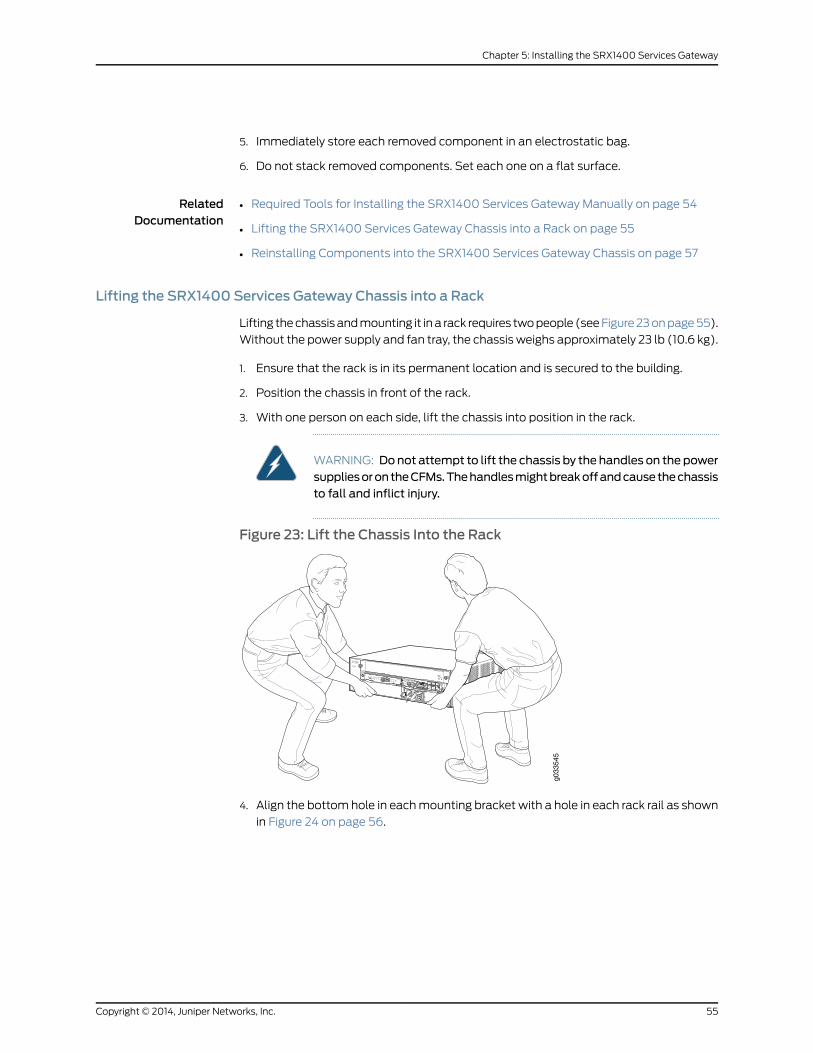
5. Immediately store each removed component in an electrostatic bag.
6. Do not stack removed components. Set each one on a flat surface.
RelatedDocumentation
Required Tools for Installing the SRX1400 Services Gateway Manually on page 54•
• Lifting the SRX1400 Services Gateway Chassis into a Rack on page 55
• Reinstalling Components into the SRX1400 Services Gateway Chassis on page 57
Lifting the SRX1400 Services Gateway Chassis into a Rack
Lifting the chassis and mounting it in a rack requires two people (see Figure 23 on page 55).
Without the power supply and fan tray, the chassis weighs approximately 23 lb (10.6 kg).
1. Ensure that the rack is in its permanent location and is secured to the building.
2. Position the chassis in front of the rack.
3. With one person on each side, lift the chassis into position in the rack.
WARNING: Donot attempt to lift the chassis by the handles on the powersuppliesorontheCFMs.Thehandlesmightbreakoffandcausethechassisto fall and inflict injury.
Figure 23: Lift the Chassis Into the Rackg0
3354
5
4. Align the bottom hole in each mounting bracket with a hole in each rack rail as shown
in Figure 24 on page 56.
55Copyright © 2014, Juniper Networks, Inc.
Chapter 5: Installing the SRX1400 Services Gateway

Figure 24: AttachMounting Hardware for Two-Post Rack
g033
516
• For front-mounting the chassis in a two-post rack, align the bottom hole in each
mounting bracket at the front edge of the chassis.
• For rear-mounting the chassis in a two-post rack, align the bottom hole in each
mounting bracket at the rear edge of the chassis.
NOTE: Similarly, you can front-mount or rear-mount the chassis in afour-post rack. However, there is no support shelf provided for theunsupported edge on which the chassis can rest.
5. Use the screws to attach the left and right brackets to the rack.
6. Visually inspect the alignment of the chassis. If the chassis is installed properly in the
rack, all the mounting screws on one side of the rack should be aligned with the
mounting screws on the opposite side, and the chassis should be level.
RelatedDocumentation
Required Tools for Installing the SRX1400 Services Gateway Manually on page 54•
• Removing Components from the Chassis for Manual Lifting of the SRX1400 Services
Gateway on page 54
• Reinstalling Components into the SRX1400 Services Gateway Chassis on page 57
Copyright © 2014, Juniper Networks, Inc.56
SRX1400 Services Gateway Hardware Guide

Reinstalling Components into the SRX1400 Services Gateway Chassis
To reinstall the components into the SRX1400 Services Gateway chassis:
1. Attach an electrostatic discharge (ESD) grounding strap to your bare wrist, and connect
the strap to one of the ESD points on the chassis. For more information about ESD,
see the SRX1400 Services Gateway hardware documentation at
www.juniper.net/techpubs.
2. Identify the locations in the chassis where you will reinstall the removed components.
Use the label you have marked on each removed component to identify the component
and its correct location in the chassis.
3. Slide each component into the chassis evenly so that it does not become stuck or
damaged.
4. Tighten the latching levers or captive screws for each component as appropriate.
NOTE: Do not expose the empty CFM slots during storage or transportation.Use appropriate covers (blank panel for CFM slot 2 and filler cover for theadjacent CFM slots 1 and 3) to prevent any dust or foreign objects fromdamaging the electronics.
RelatedDocumentation
• Required Tools for Installing the SRX1400 Services Gateway Manually on page 54
• Removing Components from the Chassis for Manual Lifting of the SRX1400 Services
Gateway on page 54
• Lifting the SRX1400 Services Gateway Chassis into a Rack on page 55
57Copyright © 2014, Juniper Networks, Inc.
Chapter 5: Installing the SRX1400 Services Gateway

Copyright © 2014, Juniper Networks, Inc.58
SRX1400 Services Gateway Hardware Guide

CHAPTER 6
InstallingAdditionalComponents into theSRX1400 Services Gateway
This chapter includes the following topics:
• Installing a Network and Services Processing Card in an SRX1400 Services
Gateway on page 59
• Installing an SPC in an SRX1400 Services Gateway on page 61
• Installing an NPC in an SRX1400 Services Gateway on page 63
• Installing an IOC or NP-IOC in an SRX1400 Services Gateway on page 65
• Installing a System I/O Card into the SRX1400 Services Gateway on page 67
• Installing an AC Power Supply in the SRX1400 Services Gateway on page 68
• Installing a DC Power Supply in the SRX1400 Services Gateway on page 69
Installing a Network and Services Processing Card in an SRX1400 Services Gateway
You install the NSPC in the CFM slots labeled 1 and 3 in the front panel of the SRX1400
Services Gateway. These two slots combine into a double-wide slot that accommodates
the NSPC.
Before installing your card, see “SRX1400 Services Gateway Front Panel” on page 15 to
identify the CFM1 and CFM3 slots.
NOTE: You can install either an NSPC, or a combination of SRX3000 SeriesServices Gateway Network Processing Card (NPC) and Services ProcessingCard (SPC), on theSRX1400ServicesGateway. Youmust use adouble-widetray with the combination of NPC and SPC.
59Copyright © 2014, Juniper Networks, Inc.

NOTE: If an NSPC is not present, youmust install a filler cover to shield theemptyslots 1and3andto(shown inFigure25onpage60) toshield theemptyslots and to allow cooling air to circulate properly through the device.
Figure 25: SRX1400 Services Gatewaywith CFMSlots 1 and 3 Coveredby Double-Wide Filler Cover
g033
565
To install an NSPC:
1. Attach an ESD grounding strap to your bare wrist and connect the strap to one of the
ESD points on the chassis.
For more information about ESD, see “Preventing Electrostatic Discharge Damage to
the SRX1400 Services Gateway” on page 153.
2. Place the card on an antistatic mat or remove it from its electrostatic bag.
3. Identify the double-wide CFM 1 and 3 slot on the services gateway where you will
install the NSPC.
See “SRX1400 Services Gateway Front Panel” on page 15 for details about where the
individual modules can be installed.
4. Remove the double-wide filler cover from the slot by loosening its screws and sliding
it out of the slot. Save the filler cover after removing it from the slot, in case you need
it when you pack or move the chassis at a later time.
5. Orient the NSPC so that the faceplate faces you. Slide the NSPC all the way into the
card cage until you feel resistance. See Figure 26 on page 61.
Copyright © 2014, Juniper Networks, Inc.60
SRX1400 Services Gateway Hardware Guide

Figure 26: Installing a Network and Services Processing Card in anSRX1400 Services Gateway
g033
519
6. Press both of the ejector handles inward to seat the NSPC.
7. Tighten the screws on either side of the card.
You can proceed with installing other hardware components, or power supplies, or
connecting to a management device. See “Powering On the SRX1400 Services
Gateway” on page 81 to power on the SRX1400 Services Gateway.
RelatedDocumentation
Installing an NPC in an SRX1400 Services Gateway on page 63•
• Installing an SPC in an SRX1400 Services Gateway on page 61
• SRX1400 Services Gateway Hardware Components on page 14
Installing an SPC in an SRX1400 Services Gateway
There are two places where you can install an SPC in your SRX1400 Services Gateway:
• You can install an SPC in the front-panel slot labeled 1 if you also install an NPC in the
slot labeled 3. This combination of SPC and NPC replaces the full-width NSPC that is
normally installed in the SRX1400 Services Gateway to perform both services processing
and network processing functions.
• If your SRX1400 Services Gateway is running Junos OS Release 12.1X44-D10 or later,
you can install an SPC in slot2. Doing so increases the services processing performance
of the services gateway and increases its session capacity.
Before installing your card, see “SRX1400 Services Gateway Front Panel” on page 15 to
verify that you have selected an appropriate slot location.
NOTE: If a slot is not occupied by a card, youmust install a blank panel toshield the empty slot and to allow cooling air to circulate properly throughthe services gateway.
61Copyright © 2014, Juniper Networks, Inc.
Chapter 6: Installing Additional Components into the SRX1400 Services Gateway

To install an SPC:
1. Attach an ESD grounding strap to your bare wrist and connect the strap to one of the
ESD points on the chassis.
For more information about ESD, see “Preventing Electrostatic Discharge Damage to
the SRX1400 Services Gateway” on page 153.
2. Place the card on an antistatic mat or remove it from its electrostatic bag.
3. If necessary, remove the blank panel covering the slot where you are installing the
SPC. If you are installing the SPC in slot 1 in conjunction with an NPC in slot 3, remove
the double-wide filler cover from the slot by loosening its screws and sliding it out of
the slot.
4. If you are installing the SPC in slot 1 in conjunction with an NPC in slot 3, insert the
double-wide tray and insert it straight into the slot until you hear a click, indicating the
latch has closed as shown in Figure 27 on page 62.
Figure 27: Installing Double-Wide Tray on SRX1400 Services Gateway
g033
553
5. Orient the SPC so that the faceplate faces you. Slide the SPC all the way into the card
cage until you feel resistance. See Figure 28 on page 62 and Figure 29 on page 63.
Figure 28: Installing an SPC in Slot 1 of the SRX1400 Services Gateway
g033
520
012
34
SRX3K-SPC-1-10-40 SRX3K-NPC
Copyright © 2014, Juniper Networks, Inc.62
SRX1400 Services Gateway Hardware Guide

Figure 29: Installing an SPC in Slot 2 of the SRX1400 Services Gateway
g033
569
012
34
6. Tighten the screws on either side of the card.
You can proceed with installing other hardware components or power supplies, or
connecting to a management device. See “Powering On the SRX1400 Services Gateway”
on page 81 to power on the SRX1400 Services Gateway.
WARNING: Never lift the services gateway using the handles on the frontpanels of the SPC or other CFM cards. The handlesmight come off, causingthe chassis to drop and inflicting possible grave injury.
RelatedDocumentation
SPCs for the SRX1400 Services Gateway on page 24•
• Troubleshooting Services Processing Cards on the SRX1400 Services Gateway on
page 111
• Replacing an SPC on the SRX1400 Services Gateway on page 128
Installing an NPC in an SRX1400 Services Gateway
NOTE: The SRX1400 Services Gateway is not normally equipped with anNPC. Inmost configurations, network processing functions are performedbythe NSPC.
You can install an NPC in the front-panel slot labeled 3 if you also install an SPC in the
slot labeled 1. This combination of SPC and NPC replaces the full-width NSPC that is
normally installed in the SRX1400 Services Gateway to perform both services processing
and network processing functions.
NOTE: If a slot is not occupied by a card, youmust install a blank panel toshield the empty slot and to allow cooling air to circulate properly throughthe services gateway.
63Copyright © 2014, Juniper Networks, Inc.
Chapter 6: Installing Additional Components into the SRX1400 Services Gateway

NOTE: To install the NPC and SPC on the SRX1400 Services Gateway, youmust order the double-wide tray (SRX1K3K-2CFM-TRAY) to hold the twosingle-wideCFMs (NPCandSPC) separately. Contact your JuniperNetworkscustomer service representative for more information.
To install an NPC:
1. Attach an ESD grounding strap to your bare wrist and connect the strap to one of the
ESD points on the chassis. For more information about ESD, see “Preventing
Electrostatic Discharge Damage to the SRX1400 Services Gateway” on page 153.
2. Place the card on an antistatic mat or remove it from its electrostatic bag.
3. If necessary, remove the filler cover from the slot by loosening its screws and sliding
it out of the slot.
4. Insert the double-wide tray and insert it straight into the slot until you hear a click,
indicating the latch has closed as shown in Figure 30 on page 64.
Figure 30: Installing a Double-Wide Tray on the SRX1400 ServicesGateway
g033
553
5. Orient the NPC so that the faceplate faces you. Slide the NPC all the way into the card
cage until you feel resistance. See Figure 31 on page 64
Figure 31: Installing an NPC on the SRX1400 Services Gateway
g033
534
012
34
SRX3K-NPC
SRX3K-SPC-1-10-40
6. Tighten the screws on either side of the card.
Copyright © 2014, Juniper Networks, Inc.64
SRX1400 Services Gateway Hardware Guide

You can proceed with installing other hardware components, or power supplies, or
connecting to a management device. See “Powering On the SRX1400 Services Gateway”
on page 81 to power on the SRX1400 Services Gateway.
WARNING: Never lift the services gateway using the handles on the frontpanels of the NPC or other CFM cards. The handlesmight come off, causingthe chassis to drop and inflicting possible grave injury.
RelatedDocumentation
NPCs for the SRX1400 Services Gateway on page 26•
• Replacing a Network Processing Card on the SRX1400 Services Gateway on page 127
• Troubleshooting an NPC on the SRX1400 Services Gateway on page 112
Installing an IOC or NP-IOC in an SRX1400 Services Gateway
You can install an IOC or NP-IOC in slot 2 on the SRX1400 Services Gateway front panel.
See “SRX1400 Services Gateway Front Panel” on page 15 for front panel slot locations.
To install an IOC or NP-IOC:
1. Attach an ESD grounding strap to your bare wrist and connect the strap to one of the
ESD points on the chassis.
For more information about ESD, see “Preventing Electrostatic Discharge Damage to
the SRX1400 Services Gateway” on page 153.
2. If you are installing an IOC, power off the services gateway if it is powered on. If you
are replacing An NP-IOC, you can leave the services gateway powered on.
To power off the services gateway, press the Power button on the front panel of the
System I/O Card (SYSIOC) for three to five seconds.
The PWR LED blinks to show you that the services gateway is shutting down.
3. Place the IOC or NP-IOC on an antistatic mat or remove it from its electrostatic bag.
4. Identify the slot on the services gateway where you will install the IOC or NP-IOC.
See “SRX1400 Services Gateway Front Panel” on page 15 for details about where the
individual modules can be installed.
65Copyright © 2014, Juniper Networks, Inc.
Chapter 6: Installing Additional Components into the SRX1400 Services Gateway

5. Orient the IOC or NP-IOC so that the faceplate faces you. Slide the IOC or NP-IOC all
the way into the card cage until you feel resistance.
g033
538
6. Tighten the screws on either side of the card.
7. For an NP-IOC or an IOC that uses fiber interfaces, install SFP, SFP+, or XFP
transceivers as appropriate into the sockets on the IOC or NP-IOC:
NOTE: We strongly recommend the use of Juniper Networks SFP, SFP+,and XFP transceivers. We cannot guarantee correct operation if othertransceivers are used. The transceiver type can be different in each port,as long as a Juniper Networks-support transceiver part number is used.
a. Take each new transceiver to be installed out of its electrostatic bag and identify
the port on the IOC or NP-IOC where it will be installed.
b. Verify that each transceiver is covered with a rubber safety cap. Cover any
transceivers without a safety cap.
c. Remove the rubber dust covers from each SFP, SFP+, or XFP socket in which you
will install a transceiver.
d. Carefully align the transceiver with the sockets in the IOC or NP-IOC. The connectors
should face the IOC or NP-IOC.
e. Slide the transceiver until the connector is seated in the IOC or NP-IOC slot. If you
are unable to fully insert the transceiver, make sure the connector is facing the right
way.
f. Close the ejector handle of the transceiver.
8. For fiber interfaces, remove the rubber safety cap from each transceiver and cable.
Copyright © 2014, Juniper Networks, Inc.66
SRX1400 Services Gateway Hardware Guide

WARNING: Do not look directly into a fiber-optic transceiver or into theends of fiber-optic cables. Fiber-optic transceivers and fiber-optic cableconnected to a transceiver emit laser light that can damage your eyes.
9. Insert the appropriate cables into the cable connector ports on each IOC or NP-IOC.
Secure the cables so that they are not supporting their own weight. Place excess cable
out of the way in a neatly coiled loop. Placing fasteners on a loop helps to maintain
its shape.
CAUTION: Do not let fiber-optic cable hang free from the connector. Donot allow fastened loops of cable to dangle, which stresses the cable atthe fastening point.
CAUTION: Avoid bending fiber-optic cable beyond its minimum bendradius.Anarc smaller thana few inches indiameter candamage thecableand cause problems that are difficult to diagnose.
WARNING: Never lift the services gateway using the handles on the frontpanels of the IOC, NP-IOC, or other CFM cards. The handlesmight come off,causing the chassis to drop and inflicting possible grave injury.
RelatedDocumentation
SRX1400 Services Gateway Hardware Components on page 14•
Installing a System I/O Card into the SRX1400 Services Gateway
Before installing your card, see “SRX1400 Services Gateway Front Panel” on page 15 to
verify that you have selected an appropriate slot location.
To install a SYSIOC on an SRX1400 Services Gateway:
1. Attach an ESD grounding strap to your bare wrist and connect the strap to one of the
ESD points on the chassis.
For more information about ESD, see “Preventing Electrostatic Discharge Damage to
the SRX1400 Services Gateway” on page 153.
2. Place the SYSIOC on an antistatic mat or remove it from its electrostatic bag.
3. Identify the slot on the services gateway where you will install the SYSIOC.
See “SRX1400 Services Gateway Front Panel” on page 15 for details about where the
individual modules can be installed.
67Copyright © 2014, Juniper Networks, Inc.
Chapter 6: Installing Additional Components into the SRX1400 Services Gateway

4. Orient the SYSIOC so that the faceplate faces you. Slide the SYSIOC all the way into
the card cage until you feel resistance.
5. Press both of the ejector handles inward to seat the SYSIOC.
6. Tighten the screws on either side of the card.
7. Insert the appropriate cables into the cable connector ports (ports 0-5) and small
form-factor pluggable (SFP) transceivers (ports 6-11) on SYSIOC as required. Secure
the cables so that they are not supporting their own weight. Place excess cable out
of the way in a neatly coiled loop. Placing fasteners on a loop helps to maintain its
shape.
You can proceed with installing other hardware components, or power supplies, or
connecting to a management device. See “Powering On the SRX1400 Services Gateway”
on page 81 to power on the SRX1400 Services Gateway.
RelatedDocumentation
SRX1400 Services Gateway SYSIOCs on page 17•
• SRX1400 Services Gateway Hardware Components on page 14
• Installing an AC Power Supply in the SRX1400 Services Gateway on page 68
• Installing a DC Power Supply in the SRX1400 Services Gateway on page 69
Installing an AC Power Supply in the SRX1400 Services Gateway
To install an AC power supply:
1. Attach an ESD grounding strap to your bare wrist and connect the strap to one of the
ESD points on the chassis.
For more information about ESD, see “Preventing Electrostatic Discharge Damage to
the SRX1400 Services Gateway” on page 153.
2. Orient the power supply so that the locking lever is on the left, as shown in
Figure 32 on page 68.
Figure32: InstallinganACPowerSupply in theSRX1400ServicesGateway
g033
539
Copyright © 2014, Juniper Networks, Inc.68
SRX1400 Services Gateway Hardware Guide

3. Using both hands, slide the power supply straight into the chassis until the power
supply is fully seated in the chassis slot. The power supply faceplate should be flush
with any adjacent power supply faceplate or blank installed in the power supply slot.
4. Proceed with connecting the power supply to AC power. See “Connecting the SRX1400
Services Gateway to an AC Power Supply” on page 77 for information on connecting
the power supply to AC power.
RelatedDocumentation
SRX1400 Services Gateway Power Supplies Overview on page 29•
• SRX1400 Services Gateway AC Power Supply on page 30
• Installing a DC Power Supply in the SRX1400 Services Gateway on page 69
• Connecting the SRX1400 Services Gateway to an AC Power Supply on page 77
Installing a DC Power Supply in the SRX1400 Services Gateway
To install a DC power supply:
1. Ensure that the voltage across the DC power source cable leads is 0 V and that there
is no chance that the cable leads might become active during installation.
2. Attach an ESD grounding strap to your bare wrist and connect the strap to one of the
ESD points on the chassis. For more information about ESD, see “Preventing
Electrostatic Discharge Damage to the SRX1400 Services Gateway” on page 153.
3. Orient the power supply so that the locking lever is on the left, as shown in
Figure 33 on page 69.
Figure33: InstallingaDCPowerSupply in theSRX1400ServicesGateway
g033
548
4. Using both hands, slide the power supply straight into the chassis until the power
supply is fully seated in the chassis slot. The power supply faceplate should be flush
with any adjacent power supply faceplate.
5. Proceed with connecting the power supply to DC power. See “Connecting the SRX1400
Services Gateway to a DC Power Supply” on page 80.
RelatedDocumentation
• SRX1400 Services Gateway Power Supplies Overview on page 29
• SRX1400 Services Gateway DC Power Supply on page 31
69Copyright © 2014, Juniper Networks, Inc.
Chapter 6: Installing Additional Components into the SRX1400 Services Gateway

• Installing an AC Power Supply in the SRX1400 Services Gateway on page 68
• Connecting the SRX1400 Services Gateway to a DC Power Supply on page 80
Copyright © 2014, Juniper Networks, Inc.70
SRX1400 Services Gateway Hardware Guide

CHAPTER 7
Connecting the SRX1400 ServicesGateway
This chapter includes the following topics:
• Connecting the SRX1400 Services Gateway to a Management Device on page 71
Connecting the SRX1400 Services Gateway to aManagement Device
After you have installed the services gateway into the rack, attach one or more external
devices to the ports on the System I/O card (SYSIOC) that connect to the installed
Routing Engine for management and service operations.
This topic includes the following sections:
• Connecting the SRX1400 Services Gateway to a Network for Out-of-Band
Management on page 71
• Connecting the SRX1400 Services Gateway to a Management Console or an Auxiliary
Device on page 72
Connecting the SRX1400 Services Gateway to a Network for Out-of-BandManagement
To connect the Routing Engine to a network for out-of-band management:
1. Plug one end of an Ethernet cable with RJ-45 connectors (see Figure 34 on page 72)
into the RE ETHERNET port on the front of the SYSIOC.
71Copyright © 2014, Juniper Networks, Inc.

Figure 34: Ethernet Cable Connector
g033
544
2. Plug the other end of the cable into the management device.
3. Proceed with grounding and powering on the device.
RelatedDocumentation
Connecting the SRX1400 Services Gateway to a Management Console or an Auxiliary
Device on page 72
•
• SRX1400 Services Gateway Software Configuration Overview on page 85
• Performing Initial Software Configuration on the SRX1400 Services Gateway (CLI
Procedure) on page 86
Connecting the SRX1400 Services Gateway to aManagement Console or an Auxiliary Device
To use a system console to configure and manage the Routing Engine, use an RJ-45
cable to connect it to one of the CONSOLE ports on the SYSIOC.
To connect a management console or an auxiliary device:
1. Plug the RJ-45 end of the cable (see Figure 35 on page 73) into the CONSOLE port on
the SYSIOC.
Copyright © 2014, Juniper Networks, Inc.72
SRX1400 Services Gateway Hardware Guide

Figure 35: Console Cable Connector
g033
543
2. Plug the female DB-9 end into the device’s serial port.
NOTE:
For console devices, configure the serial port to the following values:
• Baud rate—9600
• Parity—N
• Data bits—8
• Stop bits—1
• Flow control—none
3. Proceed with grounding and powering on the device.
You can start performing initial software configuration on the SRX1400 Services
Gateway after the device is up.
RelatedDocumentation
• Connecting the SRX1400 Services Gateway to a Network for Out-of-Band Management
on page 71
• SRX1400 Services Gateway Software Configuration Overview on page 85
• Performing Initial Software Configuration on the SRX1400 Services Gateway (CLI
Procedure) on page 86
73Copyright © 2014, Juniper Networks, Inc.
Chapter 7: Connecting the SRX1400 Services Gateway

Copyright © 2014, Juniper Networks, Inc.74
SRX1400 Services Gateway Hardware Guide
CHAPTER 8
Grounding and Providing Power to theSRX1400 Services Gateway
This chapter includes the following topics:
• Required Tools and Parts for Grounding and Providing Power to the SRX1400 Services
Gateway on page 75
• Grounding the SRX1400 Services Gateway on page 76
• Connecting the SRX1400 Services Gateway to an AC Power Supply on page 77
• Connecting the SRX1400 Services Gateway to a DC Power Supply on page 80
• Powering On the SRX1400 Services Gateway on page 81
• Powering Off the SRX1400 Services Gateway on page 82
Required Tools andParts for Grounding andProvidingPower to theSRX1400ServicesGateway
To ground and provide power to the device, you need the following tools and parts:
• Phillips (+) screwdrivers, numbers 1 and 2
• 2.5-mm flat-blade (–) screwdriver
• Wire cutters
• Electrostatic discharge (ESD) grounding wrist strap
RelatedDocumentation
Grounding the SRX1400 Services Gateway on page 76•
• Connecting the SRX1400 Services Gateway to an AC Power Supply on page 77
• Connecting the SRX1400 Services Gateway to a DC Power Supply on page 80
• Powering On the SRX1400 Services Gateway on page 81
• Powering Off the SRX1400 Services Gateway on page 82
75Copyright © 2014, Juniper Networks, Inc.

Grounding the SRX1400 Services Gateway
WARNING: Tomeet safety and electromagnetic interference (EMI)requirements and to ensure proper operation, youmust properly ground theservices gateway chassis before connecting power.
CAUTION: Before you connect power to the services gateway, a licensedelectricianmust attach a cable lug to the grounding cable that you use. Acable with an incorrectly attached lug can damage the device (for example,by causing a short circuit).
To connect the services gateway to earth ground:
1. Verify that a licensed electrician has attached the cable lug provided with the services
gateway to the grounding cable. The cable must be 14-AWG (2.1 mm2), minimum
60°C wire.
2. Attach an ESD grounding strap to your bare wrist, and connect the strap to an approved
site ESD grounding point. See the instructions for your site.
3. Ensure that all grounding surfaces are clean and brought to a bright finish before you
make the grounding connections.
4. Connect the grounding cable to a proper earth ground.
5. Detach the ESD grounding strap from the site ESD grounding point.
6. With the ESD grounding strap attached to your bare wrist, connect the strap to one
of the ESD points on the chassis.
7. Place the grounding cable lug over the grounding point—a pair of M5 holes to the left
of the power supply slots. See Figure 36 on page 77.
Copyright © 2014, Juniper Networks, Inc.76
SRX1400 Services Gateway Hardware Guide

Figure36:ConnecttheGroundingCabletotheSRX1400ServicesGateway
g033
542
8. Secure the grounding cable lug to the chassis using washers and screws.
9. Dress the grounding cable, and verify that it does not touch or block access to device
components and it does not cause a tripping hazard.
RelatedDocumentation
Required Tools and Parts for Grounding and Providing Power to the SRX1400 Services
Gateway on page 75
•
• Powering On the SRX1400 Services Gateway on page 81
• Powering Off the SRX1400 Services Gateway on page 82
Connecting the SRX1400 Services Gateway to an AC Power Supply
You connect AC power to the services gateway by attaching power cords from the AC
power sources to the AC appliance inlets located on the power supplies.
WARNING: Tomeet safety and electromagnetic interference (EMI)requirements and to ensure proper operation, youmust properly ground theservices gateway chassis before connecting power. See “Grounding theSRX1400 Services Gateway” on page 76 for instructions.
CAUTION: Do notmix AC and DC power supplies within the same servicesgateway. Damage to the services gatewaymight occur.
77Copyright © 2014, Juniper Networks, Inc.
Chapter 8: Grounding and Providing Power to the SRX1400 Services Gateway

To connect the AC power cords to the services gateway for each power supply:
1. Locate the power cord or cords with the type of plug appropriate for your geographical
location to connect the device to AC power.
For more information about model numbers, see the SRX1400 Services Gateway
hardware documentation at www.juniper.net/techpubs.
NOTE: The SRX1400 Services Gateways now ship with a retainer clip forthe power cord.
2. If your services gateway is equipped with a wire bail:
a. Insert the appliance coupler end of the power cord into the appliance inlet on the
power supply.
b. Snap the wire bail on the power supply over the power cord to prevent the power
cord from accidentally disengaging.
Figure 37: Connect the Chassis to AC Power (Using aWire Bail)
g033
522
3. If your services gateway is equipped with a retainer clip for the power cord:
a. Squeeze the two sides of the power cord retainer clip and insert the L-shaped ends
of the retainer clip into the holes in the bracket on each side of the AC appliance
inlet.
b. Insert the appliance coupler end of the power cord into the appliance inlet on the
power supply.
c. Push the power cord into the slot in the adjustment nut of the power cord retainer
clip. Turn the nut until it is snug against the base of the coupler.
Copyright © 2014, Juniper Networks, Inc.78
SRX1400 Services Gateway Hardware Guide

Figure 38: Connect the Chassis to AC Power (Using a Retainer Clip)
1. Adjustment nut
2. Retainer clip
4. Insert the power cord plug into an external AC power source receptacle.
NOTE: Each power supply must be connected to a dedicated AC powerfeed and a dedicated external circuit breaker. We recommend that youuse a 15 A (250 VAC)minimum circuit breaker, or as permitted by localcode.
5. Dress the power cord appropriately. Verify that the power cord does not block the air
exhaust or access to device components and does not cause a tripping hazard.
6. Repeat Steps 1 through 5 for the second power supply.
If the PWR LED indicates that the power supply is not functioning normally, repeat the
installation and cabling procedures.
NOTE: If power is lost to the services gateway, the Power-On/Power-Offstate is retained. For example, if the services gateway loses power while thedevice is on, when power returns, the device will still be in the On state.
RelatedDocumentation
Required Tools and Parts for Grounding and Providing Power to the SRX1400 Services
Gateway on page 75
•
• SRX1400 Services Gateway AC Power Supply on page 30
• Grounding the SRX1400 Services Gateway on page 76
• Connecting the SRX1400 Services Gateway to a DC Power Supply on page 80
• Powering On the SRX1400 Services Gateway on page 81
• SRX1400 Services Gateway AC Power System Electrical Specifications on page 192
• SRX1400 Services Gateway AC Power Supply Electrical Specifications on page 193
79Copyright © 2014, Juniper Networks, Inc.
Chapter 8: Grounding and Providing Power to the SRX1400 Services Gateway

Connecting the SRX1400 Services Gateway to a DC Power Supply
You connect DC power to the services gateway by attaching power cables from the
external DC power sources to the terminal studs on the power supply faceplates.
WARNING: Tomeet safety and electromagnetic interference (EMI)requirements and to ensure proper operation, youmust properly ground theservices gateway chassis before connecting power. See “Grounding theSRX1400 Services Gateway” on page 76 for instructions.
WARNING: Before performing the following procedure, ensure that power isremoved from theDC circuit. To ensure that all power is off, locate the circuitbreaker on the panel board that services the DC circuit, switch the circuitbreaker to the off position, and tape the switch handle of the circuit breakerin the off position.
CAUTION: Do notmix AC and DC power supplies within the same servicesgateway. Damage to the services gatewaymight occur.
CAUTION: Before you connect power to the services gateway, a licensedelectricianmust attach appropriate cable lugs to the grounding and powercables that you use. A cable with an incorrectly attached lug can damagethe device (for example, by causing a short circuit).
To connect the DC source power cables to the services gateway for each power supply:
1. Switch off the dedicated facility circuit breakers. Ensure that the voltage across the
DC power source cable leads is 0 V and that there is no chance that the cable leads
might become active during installation.
2. Remove the clear plastic cover that protects the terminal studs on the faceplate.
3. Verify that the DC power cables are correctly labeled before making connections to
the power supply.
In a typical power distribution scheme where the return is connected to chassis ground
at the battery plant, you can use a multimeter to verify that the ohm output of the
-48V and RTN DC cables to chassis ground. The cable with very large resistance
(indicating an open circuit) to chassis ground will be -48V, and the cable with very
low resistance (indicating a closed circuit) to chassis ground will be RTN.
CAUTION: Youmust ensure that power connectionsmaintain the properpolarity. The power source cablesmight be labeled (+)and (–) to indicate
Copyright © 2014, Juniper Networks, Inc.80
SRX1400 Services Gateway Hardware Guide

their polarity. There is no standard color coding for DC power cables. Thecolor coding usedby the externalDCpower source at your site determinesthe color coding for the leads on the power cables that attach to theterminal studs on each power supply.
4. Remove the screws and square washers from the terminals, using a Phillips (+)
screwdriver, number 2.
5. Secure each power cable lug to the terminals with the square washers and the screws.
Apply between 23 in.-lb (2.6 Nm) and 25 in.-lb (2.8 Nm) of torque to each screw.
• Secure each positive (+) DC source power cable lug to a RTN (return) terminal.
• Secure each negative (–) DC source power cable lug to a -48V (input) terminal.
6. Replace the clear plastic cover over the terminal studs on the faceplate.
7. Verify that the power cables are connected correctly, that they are not touching or
blocking access to services gateway components, and they do not cause a tripping
hazard.
8. Repeat Steps 1 through 7 for the second power supply, if you are installing one.
NOTE: If power is lost to the services gateway, the Power-On/Power-Offstate is retained. For example, if the services gateway loses power while thedevice is on, when power returns, the device will still be in the On state.
RelatedDocumentation
Required Tools and Parts for Grounding and Providing Power to the SRX1400 Services
Gateway on page 75
•
• Grounding the SRX1400 Services Gateway on page 76
• Connecting the SRX1400 Services Gateway to an AC Power Supply on page 77
• Powering On the SRX1400 Services Gateway on page 81
• SRX1400 Services Gateway DC Power System Electrical Specifications on page 188
• SRX1400 Services Gateway DC Power Supply Electrical Specifications on page 188
Powering On the SRX1400 Services Gateway
To power on the services gateway:
1. Ensure that you have connected the AC power cord or DC power cables to the device.
2. Insert the plug into an AC power source receptacle (for AC-powered devices).
Or
Attach the power cable to the DC power source (for DC-powered devices).
81Copyright © 2014, Juniper Networks, Inc.
Chapter 8: Grounding and Providing Power to the SRX1400 Services Gateway

The device starts automatically as the power supply completes its startup sequence.
The Power LED blinks during startup and remains on steadily when the device is operating
normally.
NOTE:
• If thedevicedoesnot power onafter connecting to thepower supply, pressthe POWER button on the front of the SYSIOC for 3 to 5 seconds to poweron the device.
• The Routing Engine, the SYSIOC, and at least one power supply must beinstalled on the SRX1400 Services Gateway for the device to power on.
• If power is lost to the services gateway, the Power-On/Power-Off state isretained. For example, if the services gateway losespowerwhile thedeviceis on, when power returns, the device will still be in the On state.
RelatedDocumentation
Connecting the SRX1400 Services Gateway to an AC Power Supply on page 77•
• Connecting the SRX1400 Services Gateway to a DC Power Supply on page 80
• Powering Off the SRX1400 Services Gateway on page 82
Powering Off the SRX1400 Services Gateway
You can power off the services gateway in one of the following ways:
• Graceful shutdown—Press and the POWER button on the front of the SYSIOC for 3 to
5 seconds to initiate graceful shutdown. The device begins gracefully shutting down
the operating system and then powers itself off.
• Forced shutdown—Press the POWER button and hold it for 15 seconds to power down
the device immediately.
You need to press the POWER button again to power on the device.
CAUTION:
Use the graceful shutdownmethod to power off or reboot the servicesgateway. Use the forced shutdownmethod as a last resort to recover theservicesgateway if theservicesgatewayoperatingsystemisnot respondingto the graceful shutdownmethod.
By default, even if you press the POWER button and hold it for 15 seconds(that is, more than 5 seconds), the devicewill still do a graceful shutdownif it is responsive and operating normally. The device will resort to forcedshutdown only if the operating system does not initiate the gracefulshutdown process first.
Copyright © 2014, Juniper Networks, Inc.82
SRX1400 Services Gateway Hardware Guide

To remove power completely from the device, unplug the AC power cord (for AC-powered
devices) or switch off the DC power source (for DC-powered devices). After powering
off the device, wait for at least 10 seconds before powering on the device again. After
powering on the device, wait for at least 10 seconds before powering it off.
CAUTION: Forced shutdown can result in data loss and corruption of the filesystem.
RelatedDocumentation
• Connecting the SRX1400 Services Gateway to an AC Power Supply on page 77
• Connecting the SRX1400 Services Gateway to a DC Power Supply on page 80
• Powering On the SRX1400 Services Gateway on page 81
83Copyright © 2014, Juniper Networks, Inc.
Chapter 8: Grounding and Providing Power to the SRX1400 Services Gateway

Copyright © 2014, Juniper Networks, Inc.84
SRX1400 Services Gateway Hardware Guide

CHAPTER 9
Performing Initial Software Configurationon the SRX1400 Services Gateway
This chapter includes the following topics:
• SRX1400 Services Gateway Software Configuration Overview on page 85
• Performing Initial Software Configuration on the SRX1400 Services Gateway (CLI
Procedure) on page 86
• Performing Initial Software Configuration Using J-Web on page 90
SRX1400 Services Gateway Software Configuration Overview
The services gateway is shipped with Junos OS preinstalled and ready to be configured
when the services gateway is powered on. You can configure the services gateway using
the CLI, the J-Web interface, SSH, or Telnet. However, you can perform initial configuration
using the CLI only.
The SRX1400 Services Gateway includes Junos OS images in:
• The CompactFlash card in the Routing Engine
• The hard disk in the Routing Engine
NOTE: You can also use a Junos OS image stored on a USB flash drive thatyou insert into the Routing Engine faceplate.
When the services gateway boots, the following sequence of events occurs:
1. The device attempts to start the image on the USB flash drive (if available).
2. The device attempts to start the image from the CompactFlash card if the USB flash
drive is not inserted into the Routing Engine or if the first attempt fails.
3. The device attempts to start the image from the hard disk if the first two methods
fail.
85Copyright © 2014, Juniper Networks, Inc.

You configure the services gateway by using CLI commands, either on a console device
attached to the CONSOLE port on the SYSIOC or over a Telnet connection to a network
connected to the RE ETHERNET port on the SYSIOC.
Gather the following information before configuring the services gateway:
• Name the services gateway will use on the network
• Domain name the services gateway will use
• IP address and prefix length information for the Ethernet interface
• IP address of a default router
• IP address of a DNS server
• Password for the root user
RelatedDocumentation
Connecting the SRX1400 Services Gateway to a Network for Out-of-Band Management
on page 71
•
• Connecting the SRX1400 Services Gateway to a Management Console or an Auxiliary
Device on page 72
• Performing Initial Software Configuration on the SRX1400 Services Gateway (CLI
Procedure) on page 86
Performing Initial Software Configuration on the SRX1400 Services Gateway (CLIProcedure)
This sample procedure explains how you can create an initial configuration using CLI
commands to connect the services gateway to the network. For complete information
about enabling the services gateway to forward traffic, including examples, see the
appropriate Junos OS configuration guides at www.juniper.net/techpubs/.
To configure Junos OS:
1. Verify that the device is powered on.
2. Log in as the root user. There is no password.
3. Start the CLI.
root#cliroot#
4. Enter configuration mode.
configure[edit]root@#
5. Set the root authentication password by entering a cleartext password, an encrypted
password, or an SSH public key string (DSA or RSA).
[edit]root@# set system root-authentication plain-text-passwordNew password: passwordRetype new password: password
Copyright © 2014, Juniper Networks, Inc.86
SRX1400 Services Gateway Hardware Guide

6. Configure an administrator account on the device. When you are prompted, enter the
password for the administrator account.
[edit]root@# set system login user admin class super-user authentication plain-text-passwordNew password: passwordRetype new password: password
7. Commit the configuration to activate it on the services gateway.
[edit]root@# commit
8. Log in as the administrative user you configured in Step 6.
9. Configure the name of the services gateway. If the name includes spaces, enclose the
name in quotation marks (“ ”).
configure[edit]admin@# set system host-name host-name
10. Configure the IP address and prefix length for the services gateway Ethernet interface.
[edit]admin@# set interfaces fxp0 unit 0 family inet address address/prefix-length
11. Configure the traffic interface.
[edit]admin@# set interfaces ge-0/0/0 unit 0 family inet address address/prefix-lengthadmin@# set interfaces ge-0/0/1 unit 0 family inet address address/prefix-length
NOTE: The ge-0/0/0 interface is for the LAN, and the ge-0/0/1 interfaceis for the ISP.
12. Configure the default route.
[edit]admin@# set routing-options static route 0.0.0.0/0 next-hop gateway
13. Configure basic security zones and bind them to traffic interfaces.
[edit]admin@# set security zones security-zone trust interfaces ge-0/0/0admin@# set security zones security-zone untrust interfaces ge-0/0/1
14. Configure basic security policies.
[edit]admin@# set security policies from-zone trust to-zone untrust policy policy-namematchsource-address any destination-address any application anyadmin@# set security policies from-zone trust to-zone untrust policy policy-name then permitadmin@# set security policies from-zone untrust to-zone trust policy policy-namematchsource-address any destination-address any application anyadmin@# set security policies from-zone untrust to-zone trust policy policy-name then permit
NOTE: The actual configuration of the policies depends on yourrequirements.
15. Check the configuration for validity.
[edit]
87Copyright © 2014, Juniper Networks, Inc.
Chapter 9: Performing Initial Software Configuration on the SRX1400 Services Gateway

admin@# commit checkconfiguration check succeeds
16. Commit the configuration to activate it on the services gateway.
[edit]admin@# commitcommit complete
17. Optionally, display the configuration to verify that it is correct.
NOTE: This is a sample output. The actual output might vary dependingon your configuration requirements.
admin@# show## Last changed: 2010-08-18 05:50:46 UTCversion "10.4I0 [sharibkh]";system { host-name doc; root-authentication { encrypted-password "$1$OJJkOtOh$sxV2pvW.XX2CIhIoD7WEM1"; ## SECRET-DATA
} login { user admin { uid 2000; class super-user; authentication { encrypted-password "$1$Gx9YDUAi$V8ee8svJZN8c02X81vIKY."; ## SECRET-DATA } } user regress { uid 928; class super-user; authentication { encrypted-password "$1$SgVN0PWm$8T4GHRasDvGZV2/fXREZj/"; ## SECRET-DATA } } } services { ssh; telnet; web-management { http; } }}interfaces { ge-0/0/0 { unit 0 { family inet { address 192.1.1.1/24; } } } ge-0/0/1 { unit 0 {
Copyright © 2014, Juniper Networks, Inc.88
SRX1400 Services Gateway Hardware Guide

family inet { address 5.1.1.1/24; } } } fxp0 { unit 0 { family inet { address 10.204.210.23/23; address 192.168.10.2/24; } } }}routing-options { static { route 0.0.0.0/0 next-hop [ 10.204.211.254 5.1.1.2 ]; }}security { zones { security-zone trust { interfaces { ge-0/0/0.0; } } security-zone untrust { interfaces { ge-0/0/1.0; } } } policies { from-zone trust to-zone untrust { policy bob { match { source-address any; destination-address any; application any; } then { permit; } } } } policies { from-zone untrust to-zone trust { policy bob { match { source-address any; destination-address any; application any; } then { permit; } } } }}
89Copyright © 2014, Juniper Networks, Inc.
Chapter 9: Performing Initial Software Configuration on the SRX1400 Services Gateway

[edit]regress#
[edit]
18. Commit the configuration to activate it on the services gateway.
[edit]admin@# commit
19. Optionally, configure additional properties by adding the necessary configuration
statements. Then commit the changes to activate them on the services gateway.
[edit]admin@# commit
20. When you have finished configuring the services gateway, exit configuration mode.
[edit]admin@# exitadmin@>
NOTE: To access the device using J-Web for the first time, enter theconfigurationmode in the CLI, and set themanagement option using thecommand set system services web-management http.
If you are using an interface other than fxp0, then youmust also use thecommand set security zones security-zone trust interface interface-namehost-inbound-traffic system-services http/https to set up J-Web.
RelatedDocumentation
Connecting the SRX1400 Services Gateway to a Network for Out-of-Band Management
on page 71
•
• Connecting the SRX1400 Services Gateway to a Management Console or an Auxiliary
Device on page 72
• SRX1400 Services Gateway Software Configuration Overview on page 85
Performing Initial Software Configuration Using J-Web
• Configuring Root Authentication and the Management Interface from the CLI on page 90
• Configuring Interfaces, Zones, and Policies with J-Web on page 91
Configuring Root Authentication and theManagement Interface from the CLI
Before you can use J-Web to configure your device, you must access the CLI to perform
the initial configuration.
To configure root authentication and the management interface:
1. Log in as root. There is no password.
2. Start the CLI and enter configuration mode.
Copyright © 2014, Juniper Networks, Inc.90
SRX1400 Services Gateway Hardware Guide

root@% cliroot@>configureroot@#
3. Set the root authentication password by entering a cleartext password, an encrypted
password, or an SSH public key string (DSA or RSA).
[edit]root@# set system root-authentication plain-text-passwordNew password: passwordRetype new password: password
4. Commit the configuration to activate it on the device.
[edit]root@# commit
5. Configure the IP address and prefix length for the Ethernet management interface on
the device.
[edit]root@# set interfaces fxp0 unit 0 family inet address address/prefix-length
6. Configure the default route.
[edit]root@# set routing-options static route 0.0.0.0/0 next-hop gateway
7. Enable Web access to launch J-Web.
[edit]root@# set system services web-management http
8. Commit the configuration changes.
[edit]root@# commit
Configuring Interfaces, Zones, and Policies with J-Web
You can configure hostnames, interfaces, zones, and security policies using J-Web.
Before you begin:
• Ensure you have configured the IP address, root authentication, and default route. See
“Configuring Root Authentication and the Management Interface from the CLI” on
page 90
• Enable HTTP on the device to access J-Web. See “Configuring Root Authentication
and the Management Interface from the CLI” on page 90
Configure the device with J-Web using the following procedures.
• Configuring the Hostname on page 92
• Configuring Interfaces on page 92
• Configuring Zones and Assigning Interfaces on page 92
• Configuring Security Policies on page 93
91Copyright © 2014, Juniper Networks, Inc.
Chapter 9: Performing Initial Software Configuration on the SRX1400 Services Gateway

Configuring the Hostname
To configure the hostname:
1. Launch a Web browser from the management device.
2. Enter the IP address of the device in the URL address field.
3. Specify the default username as root and enter the password. See “Configuring Root
Authentication and the Management Interface from the CLI” on page 90.
4. Click Log In. The J-Web Dashboard page appears.
5. Select Configure>SystemProperties>System Identity, and then select Edit. The Edit
System Identity dialog box appears.
6. Enter the hostname and click OK.
7. Select Commit Options>Commit to apply the configuration changes.
You have successfully configured the hostname for the system.
Configuring Interfaces
To configure two physical interfaces:
1. From the J-Web Dashboard page, select Configure>Interfaces and select a physical
interface you want to configure.
2. Select Add>Logical Interface. The Add interface dialog box appears.
3. Set Unit = 0.
4. Select the check box for IPv4 Address to enable IPv4 addressing.
5. Click Add and enter the IPv4 address.
6. Click OK.
A message appears after your configuration changes are validated successfully.
7. Click OK.
8. Select Commit Options>Commit to apply the configuration changes.
A message appears after your configuration changes are applied successfully.
9. Click OK.
You have successfully configured the physical interface. Repeat these steps to configure
the second physical interface for the device.
Configuring Zones and Assigning Interfaces
To assign interfaces within a trust zone and an untrust zone:
1. From the J-Web Dashboard page, selectConfigure>Security>Zones/Screens and click
Add. The Add Zone dialog box appears.
2. In the Main tab, enter trust for zone name and enter the description.
Copyright © 2014, Juniper Networks, Inc.92
SRX1400 Services Gateway Hardware Guide

3. Set the zone type to Security.
4. Select the interfaces listed under Available and move them under Selected.
5. Click OK.
A message appears after your configuration changes are validated successfully.
6. Click OK.
7. Select Commit Options>Commit to apply the configuration changes.
A message appears after your configuration changes are applied successfully.
8. Click OK.
9. Repeat Steps 1 through 8 and assign another interface to an untrust zone.
You have successfully configured interfaces in a trust zone and in an untrust zone.
Configuring Security Policies
To configure security policies:
1. From the J-Web Dashboard page, select Configure>Security>Security Policy and click
Add. The Add Policy dialog box appears.
2. In the Policy tab, enter the policy name and set the policy action topermit. Then select
Zone and set the From Zone to trust and the To Zone to untrust.
3. Configure the source IP address by selecting any listed under Available and moving it
under Selected.
4. Configure the destination IP address by selectingany listed under Available and moving
it under Selected.
5. Configure the application by selecting any listed under Available and moving it under
Selected.
6. Click OK.
A message appears after your configuration changes are validated successfully.
7. Click OK.
8. Select Commit Options>Commit to apply the configuration changes.
A message appears after your configuration changes are applied successfully.
9. Click OK.
You have successfully configured the security policy.
RelatedDocumentation
• Performing Initial Software Configuration on the SRX1400 Services Gateway (CLI
Procedure) on page 86
• Performing Initial Software Configuration on the SRX3400 Services Gateway
• Performing Initial Software Configuration on the SRX3600 Services Gateway
• Initially Configuring the SRX5400 Services Gateway
93Copyright © 2014, Juniper Networks, Inc.
Chapter 9: Performing Initial Software Configuration on the SRX1400 Services Gateway

• Initially Configuring the SRX5600 Services Gateway
• Initially Configuring the SRX5800 Services Gateway
Copyright © 2014, Juniper Networks, Inc.94
SRX1400 Services Gateway Hardware Guide

PART 3
SRX1400 Services Gateway HardwareMaintenance, Replacement, andTroubleshooting Procedures
• Maintaining the SRX1400 Services Gateway Hardware Components on page 97
• Troubleshooting the SRX1400 Services Gateway on page 103
• Replacing Hardware Components on the SRX1400 Services Gateway on page 115
95Copyright © 2014, Juniper Networks, Inc.

Copyright © 2014, Juniper Networks, Inc.96
SRX1400 Services Gateway Hardware Guide

CHAPTER 10
Maintaining the SRX1400 ServicesGateway Hardware Components
This chapter includes the following topics:
• Required Tools and Parts for Maintaining the SRX1400 Services Gateway Hardware
Components on page 97
• Routine Maintenance Procedures for the SRX1400 Services Gateway on page 98
• Maintaining the Air Filter on the SRX1400 Services Gateway on page 98
• Maintaining the Fan Tray on the SRX1400 Services Gateway on page 99
• Maintaining the Routing Engine on the SRX1400 Services Gateway on page 100
• Maintaining Power Supplies on the SRX1400 Services Gateway on page 101
Required Tools and Parts for Maintaining the SRX1400 Services Gateway HardwareComponents
To maintain hardware components, you need the following tools and parts:
• ESD grounding wrist strap
• Flat-blade (–) screwdriver
• Phillips (+) screwdriver, number 1
• Phillips (+) screwdriver, number 2
RelatedDocumentation
Routine Maintenance Procedures for the SRX1400 Services Gateway on page 98•
• Maintaining Power Supplies on the SRX1400 Services Gateway on page 101
• Maintaining the Fan Tray on the SRX1400 Services Gateway on page 99
• Maintaining the Air Filter on the SRX1400 Services Gateway on page 98
97Copyright © 2014, Juniper Networks, Inc.

RoutineMaintenance Procedures for the SRX1400 Services Gateway
For optimum services gateway performance, perform the following preventive
maintenance procedures regularly:
• Inspect the installation site for moisture, loose wires or cables, and excessive dust.
Make sure that airflow is unobstructed around the device and into the air intake vents.
• Inspect the air filter, cleaning or replacing it as needed for optimum cooling system
performance. Do not run the device for more than a few minutes without the air filter
in place. For maintenance instructions, see “Maintaining the Air Filter on the SRX1400
Services Gateway” on page 98.
CAUTION: Always keep the air filter in place while the services gateway isoperating. Because the fans are very powerful, they could pull small bitsof wire or other materials into the device through the unfiltered air intake.This could damage the device components.
RelatedDocumentation
Required Tools and Parts for Maintaining the SRX1400 Services Gateway Hardware
Components on page 97
•
• Maintaining Power Supplies on the SRX1400 Services Gateway on page 101
• Maintaining the Fan Tray on the SRX1400 Services Gateway on page 99
• Maintaining the Air Filter on the SRX1400 Services Gateway on page 98
Maintaining the Air Filter on the SRX1400 Services Gateway
A dirty air filter restricts airflow in the unit, reducing the ventilation of the chassis. The
filter degrades over time. Periodically replace the filter in use, as well as spares. We
recommend that you replace the filter every 6 months.
CAUTION: Always keep the air filter in place while the services gateway isoperating. Because the fans are very powerful, they could pull small bits ofwire or other materials into the device through the unfiltered air intake. Thiscould damage the device components.
Always keep spare air filters and store them in a dark, cool, and dry place. Storing air
filters at higher temperatures, or where they can be exposed to ultraviolet (UV) radiation,
hydrocarbon emissions, or vapors from solvents, can significantly reduce their life.
RelatedDocumentation
Required Tools and Parts for Maintaining the SRX1400 Services Gateway Hardware
Components on page 97
•
• Routine Maintenance Procedures for the SRX1400 Services Gateway on page 98
• Maintaining the Fan Tray on the SRX1400 Services Gateway on page 99
Copyright © 2014, Juniper Networks, Inc.98
SRX1400 Services Gateway Hardware Guide

Maintaining the Fan Tray on the SRX1400 Services Gateway
The fan tray contains two fans that work in unison to cool the services gateway
components. If one fan fails, the host subsystem adjusts the speed of the remaining fan
to maintain proper cooling. A red alarm is triggered when a fan fails, and a yellow alarm
and red alarm is triggered when a fan tray is removed.
NOTE: The fan tray supports hot-swappable functionality. We recommendthat you reinstall the fan tray within threeminutes; otherwise, the servicesgateway temperature exceeds themaximum recommended roomtemperature and the device shuts down automatically in 4minutes.
If one fan fails, youmust replace the failed fan immediately. If the remainingfan also fails, then all the components in the device go offline automatically(when both fans fail).
To display the status of the cooling system, use theshowchassisenvironmentcommand.
The output is similar to the following:
user@host> show chassis environment
Class Item Status MeasurementTemp PEM 0 OK PEM 1 Absent Routing Engine 0 OK Routing Engine 1 Absent CB 0 Intake OK 34 degrees C / 93 degrees F CB 0 Exhaust A OK 41 degrees C / 105 degrees F CB 0 Mezz OK 34 degrees C / 93 degrees F FPC 0 Intake OK 42 degrees C / 107 degrees F FPC 0 Exhaust A OK 44 degrees C / 111 degrees F FPC 1 Intake OK 34 degrees C / 93 degrees F FPC 1 Exhaust A OK 43 degrees C / 109 degrees F FPC 1 XLR OK 52 degrees C / 125 degrees F FPC 2 Intake OK 32 degrees C / 89 degrees F FPC 2 Exhaust A OK 41 degrees C / 105 degrees F FPC 3 Intake OK 51 degrees C / 123 degrees F FPC 3 Exhaust A OK 55 degrees C / 131 degrees FFans Fan 1 OK Spinning at normal speed Fan 2 OK Spinning at normal speed
RelatedDocumentation
Required Tools and Parts for Maintaining the SRX1400 Services Gateway Hardware
Components on page 97
•
• Routine Maintenance Procedures for the SRX1400 Services Gateway on page 98
• Maintaining the Air Filter on the SRX1400 Services Gateway on page 98
• Replacing the Fan Tray on the SRX1400 Services Gateway on page 117
99Copyright © 2014, Juniper Networks, Inc.
Chapter 10: Maintaining the SRX1400 Services Gateway Hardware Components

Maintaining the Routing Engine on the SRX1400 Services Gateway
To monitor the Routing Engine, follow these guidelines:
• Check the LEDs on the Routing Engine faceplate
• Check the status of the Routing Engine using the show chassis routing-enginecommand. The output is similar to the following:
user@host> show chassis routing-engineRouting Engine status: Slot 0: Current state Master Election priority Master (default) DRAM 1023 MB Memory utilization 35 percent CPU utilization: User 0 percent Background 0 percent Kernel 2 percent Interrupt 0 percent Idle 97 percent Model RE-SRX1400 Start time 2010-07-08 13:54:21 UTC Uptime 5 days, 1 hour, 38 minutes, 53 seconds Last reboot reason 0x1:power cycle/failure Load averages: 1 minute 5 minute 15 minute 0.01 0.04 0.03
• Check the status of the chassis using the show chassis environment command. The
output is similar to the following
user@host> show chassis environmentregress@host-pubs> show chassis environmentClass Item Status MeasurementTemp PEM 0 OK PEM 1 Absent Routing Engine 0 OK Routing Engine 1 Absent CB 0 Intake OK 33 degrees C / 91 degrees F CB 0 Exhaust A OK 40 degrees C / 104 degrees F CB 0 Mezz OK 34 degrees C / 93 degrees F FPC 0 Intake OK 41 degrees C / 105 degrees F FPC 0 Exhaust A OK 43 degrees C / 109 degrees F FPC 1 Intake OK 34 degrees C / 93 degrees F FPC 1 Exhaust A OK 43 degrees C / 109 degrees F FPC 1 XLR OK 52 degrees C / 125 degrees F FPC 2 Intake OK 32 degrees C / 89 degrees F FPC 2 Exhaust A OK 40 degrees C / 104 degrees F FPC 3 Intake OK 50 degrees C / 122 degrees F FPC 3 Exhaust A OK 54 degrees C / 129 degrees FFans Fan 1 OK Spinning at normal speed Fan 2 OK Spinning at normal speed
For more information about using the CLI, see the CLI Explorer.
RelatedDocumentation
Required Tools and Parts for Maintaining the SRX1400 Services Gateway Hardware
Components on page 97
•
Copyright © 2014, Juniper Networks, Inc.100
SRX1400 Services Gateway Hardware Guide

• Routine Maintenance Procedures for the SRX1400 Services Gateway on page 98
• SRX1400 Services Gateway Routing Engine on page 27
Maintaining Power Supplies on the SRX1400 Services Gateway
To maintain the power supplies, follow these guidelines:
• To check the status of the power supplies, use the show chassis environment pemcommand. The output is similar to the following:
user@host> show chassis environment pem
PEM 0 status: State Online Temperature OK 34 degrees C / 93 degrees F AC Input: OK 118 Volts DC Output Voltage(V) Current(A) Power(W) Load(%) 12 11 132 11PEM 1 status: State Online Temperature OK 29 degrees C / 84 degrees F AC Input: OK 119 Volts DC Output Voltage(V) Current(A) Power(W) Load(%) 12 10 120 10
• Make sure that the power and grounding cables are arranged so that they do not
obstruct access to other services gateway components.
• Routinely check the PWR status LED on the SYSIOC faceplate. If this LED is solid green,
the power supplies are functioning normally.
• Routinely check the LED on the power supply faceplate. Each power supply faceplate
displays a single LED to indicate the status of the power supply. For more information,
see “SRX1400 Services Gateway AC Power Supply” on page 30 or “SRX1400 Services
Gateway DC Power Supply” on page 31.
• Periodically inspect the site to ensure that the grounding and power cables connected
to the device are securely in place and that there is no moisture accumulating near the
device.
RelatedDocumentation
• Required Tools and Parts for Maintaining the SRX1400 Services Gateway Hardware
Components on page 97
• Routine Maintenance Procedures for the SRX1400 Services Gateway on page 98
• SRX1400 Services Gateway Power Supplies Overview on page 29
101Copyright © 2014, Juniper Networks, Inc.
Chapter 10: Maintaining the SRX1400 Services Gateway Hardware Components

Copyright © 2014, Juniper Networks, Inc.102
SRX1400 Services Gateway Hardware Guide

CHAPTER 11
Troubleshooting the SRX1400 ServicesGateway
This chapter includes the following topics:
• Troubleshooting Hardware Components on the SRX1400 Services Gateway on page 103
• Juniper Networks Technical Assistance Center on page 107
• Troubleshooting the Cooling System on the SRX1400 Services Gateway on page 107
• Troubleshooting I/O Cards on the SRX1400 Services Gateway on page 108
• Troubleshooting the System I/O Card on the SRX1400 Services Gateway on page 109
• Troubleshooting the Network and Services Processing Card on the SRX1400 Services
Gateway on page 110
• Troubleshooting Services Processing Cards on the SRX1400 Services
Gateway on page 111
• Troubleshooting an NPC on the SRX1400 Services Gateway on page 112
• Troubleshooting the Power System on the SRX1400 Services Gateway on page 112
Troubleshooting Hardware Components on the SRX1400 Services Gateway
This chapter includes the following topics:
• Troubleshooting with the CLI on the SRX1400 Services Gateway on page 103
• Troubleshooting with LEDs on the SRX1400 Services Gateway on page 105
• Troubleshooting with Chassis and Interface Alarm Messages on the SRX1400 Services
Gateway on page 106
Troubleshooting with the CLI on the SRX1400 Services Gateway
The Junos OS command-line interface (CLI) is the primary tool for controlling and
troubleshooting services gateway hardware, Junos OS, routing protocols, and network
connectivity. CLI commands display information from routing tables, information specific
to routing protocols, and information about network connectivity derived from the ping
and traceroute utilities. CLI commands are entered on one or more external management
devices. These devices are connected to the services gateway through the CONSOLE
port on the SYSIOC.
103Copyright © 2014, Juniper Networks, Inc.

You can use the CLI to display details about alarms generated by interfaces and hardware
components as shown in examples below:
• Use the CLI show chassis fpc command to check the status of the installed cards. As
shown in the sample output, the value Online in the column labeled State indicates
that the card is functioning normally:
user@host> show chassis fpc Temp CPU Utilization (%) Memory Utilization (%) Temp CPU Utilization (%) Memory Utilization (%)Slot State (C) Total Interrupt DRAM (MB) Heap Buffer 0 Online 42 40 0 1024 3 27 1 Online 34 40 0 1024 3 27 2 Online 32 40 0 1024 3 27 3 Online 55 40 0 1024 3 27
• Using a question mark (?) gives you a listing of the various options for the command
as shown below:
user@host> show chassis fpc ?Possible completions: <[Enter]> Execute this command <fpc-slot> FPC slot number (0..3) detail Display detailed output pic-status Show Physical Interface Cards installed in FPC | Pipe through a command
• To view information about a particular card in the chassis, use the fpc slot option:
user@host> show chassis fpc 3
Temp CPU Utilization (%) Memory Utilization (%)Slot State (C) Total Interrupt DRAM (MB) Heap Buffer 3 Online 54 39 0 1024 3 27
• For more detailed output, add thedetailoption. The following example does not specify
a slot number, which is optional:
user@host> show chassis fpc detailregress@host-pubs> show chassis fpc detailSlot 0 information: State Online Temperature 42 degrees C / 107 degrees F Total CPU DRAM 1024 MB Total RLDRAM 0 MB Total DDR DRAM 0 MB Start time: 2010-07-08 13:56:19 UTC Uptime: 2 hours, 23 minutes Max Power Consumption 0 WattsSlot 1 information: State Online Temperature 34 degrees C / 93 degrees F Total CPU DRAM 1024 MB Total RLDRAM 0 MB Total DDR DRAM 0 MB Start time: 2010-07-08 13:56:24 UTC Uptime: 2 hours, 22 minutes, 55 seconds Max Power Consumption 0 WattsSlot 2 information: State Online Temperature 32 degrees C / 89 degrees F
Copyright © 2014, Juniper Networks, Inc.104
SRX1400 Services Gateway Hardware Guide

Total CPU DRAM 1024 MB Total RLDRAM 0 MB Total DDR DRAM 0 MB Start time: 2010-07-08 13:56:19 UTC Uptime: 2 hours, 23 minutes Max Power Consumption 0 WattsSlot 3 information: State Online Temperature 54 degrees C / 129 degrees F Total CPU DRAM 1024 MB Total RLDRAM 0 MB Total DDR DRAM 0 MB Start time: 2010-07-08 13:56:19 UTC Uptime: 2 hours, 23 minutes Max Power Consumption 0 Watts
NOTE: For further descriptions of the output from the commands, see theJunos System Basics and Services Command Reference.
NOTE: The set chassis ioc-npc-connectivity command is not supported on
the SRX1400 Services Gateway.
You can also view the chassis properties in the J-Web interface by selecting
Monitor>Chassis. For more information on troubleshooting the individual hardware
components, see the following topics:
• Troubleshooting the Cooling System on the SRX1400 Services Gateway on page 107
• Troubleshooting the System I/O Card on the SRX1400 Services Gateway on page 109
• Troubleshooting the Network and Services Processing Card on the SRX1400 Services
Gateway on page 110
• Troubleshooting the Power System on the SRX1400 Services Gateway on page 112
• Troubleshooting I/O Cards on the SRX1400 Services Gateway on page 108
Troubleshooting with LEDs on the SRX1400 Services Gateway
The SRX1400 Services Gateway LEDs, listed in Table 28 on page 105 display the status
of various components.
Table 28: LEDs on SRX1400 Services Gateway
For More InformationLabelsLEDs
• SRX1400 Services Gateway NSPCon page 23
• Troubleshooting with Chassis andInterface Alarm Messages on theSRX1400 Services Gateway onpage 106
One LED labeledOK/FAIL and SERVICEon the faceplate of following cardsindicates the CFM’s status:
• NSPC
• IOC
Commonform-factormodule(CFM) LED
105Copyright © 2014, Juniper Networks, Inc.
Chapter 11: Troubleshooting the SRX1400 Services Gateway

Table 28: LEDs on SRX1400 Services Gateway (continued)
For More InformationLabelsLEDs
• SRX1400 Services Gateway SYSIOCson page 17
• Troubleshooting with Chassis andInterface Alarm Messages on theSRX1400 Services Gateway onpage 106
The following LEDs on the SYSIOCfaceplate indicate the status of thecard. If no LEDs are lit, the RoutingEngine might still be booting or theSYSIOC is not receiving power.
• ALARM (2 LEDs)
• SIO
• HA
• PWR
• FAN
NOTE: The LED labeled as AED iscurrently not supported in this releaseand this LED always remains off.
SYSIOCLEDs
• SRX1400 Services Gateway RoutingEngine on page 27
• Troubleshooting with Chassis andInterface Alarm Messages on theSRX1400 Services Gateway onpage 106
The following LEDs on the RoutingEngine faceplate indicate the status ofthe Routing Engine and hard disk drive:
• MASTER
• HDD
• STATUS (for the Routing Engine)
• STATUS (for the Packet ForwardingEngine controller)
• OK/FAIL
RoutingEngine LEDs
• SRX1400 Services Gateway ACPower Supply on page 30
• SRX1400 Services Gateway DCPower Supply on page 31
• Troubleshooting with Chassis andInterface Alarm Messages on theSRX1400 Services Gateway onpage 106
One LED on each power supplyfaceplate indicates the status of thatpower supply.
Powersupply LEDs
TroubleshootingwithChassisand InterfaceAlarmMessagesontheSRX1400ServicesGateway
When the Routing Engine detects an alarm condition, it lights the red or yellow alarm
LED on the SYSIOC as appropriate. To view a more detailed description of the alarm
cause, use the show chassis alarms CLI command:
user@host> show chassis alarmsNo alarms currently active
There are two classes of alarm messages:
• Chassis alarms—Indicate a problem with a chassis component such as the cooling
system or power supplies.
• Interface alarms—Indicate a problem with a specific network interface.
Copyright © 2014, Juniper Networks, Inc.106
SRX1400 Services Gateway Hardware Guide

Juniper Networks Technical Assistance Center
If you need assistance while troubleshooting a services gateway, open a support case
using the Case Manager link at: http://www.juniper.net/support/ , or call 1-888-314-JTAC
(within the United States) or 1-408-745-9500 (from outside the United States).
RelatedDocumentation
Troubleshooting with the CLI on the SRX1400 Services Gateway on page 103•
• Troubleshooting with LEDs on the SRX1400 Services Gateway on page 105
• Troubleshooting with Chassis and Interface Alarm Messages on the SRX1400 Services
Gateway on page 106
Troubleshooting the Cooling System on the SRX1400 Services Gateway
The services gateway cooling system consists of a fan tray and an air filter, both of which
are located in the side of the chassis and plugged in from the rear of the chassis. The fan
tray contains two fans. The fan tray provides cooling to the components installed in the
device.
An air filter installed in the rear of the chassis helps keep dust and other particles from
entering the cooling system. To function properly, the entire cooling system requires an
unobstructed airflow and proper clearance around the site, as described in “Site
Preparation Checklist for the SRX1400 Services Gateway” on page 37.
During normal operation, the fans in the fan tray function at less than full speed. The
Routing Engine constantly monitors the temperatures detected by sensors and services
gateway components, adjusting the speed of the fans as necessary. If the services gateway
temperature exceeds the acceptable maximum, the Routing Engine turns off the power
supplies.
Table 29 on page 107 describes the alarm conditions and corrective actions for SRX1400
Services Gateway cooling system.
Table 29: SRX1400 Services Gateway Cooling SystemAlarm Conditionsand Corrective Actions
Possible Cause and Corrective ActionAlarm Indicationson SYSIO CardAlarm Conditions
1. Use the CLI to get information about thesource of an alarm condition:
user@host> show chassis alarms
2. If the CLI output lists only one fan failureand the other fan is functioning normally,the fan is most likely faulty and you needto replace the fan tray, as described in“Replacing the Fan Tray on the SRX1400Services Gateway” on page 117.
Red (critical alarmLED)
The services gateway fanhas failed.
107Copyright © 2014, Juniper Networks, Inc.
Chapter 11: Troubleshooting the SRX1400 Services Gateway

Table 29: SRX1400 Services Gateway Cooling SystemAlarm Conditionsand Corrective Actions (continued)
Possible Cause and Corrective ActionAlarm Indicationson SYSIO CardAlarm Conditions
Reinstall the fan tray.Red (critical alarmLED) and Yellow(non-critical alarmLED)
The services gateway fantray is removed
The Routing Engine constantly monitors thetemperatures detected by sensors anddevice components, and adjusts the speedof the fans as necessary.
TIP: Place your hand near the exhaust ventsat the side of the chassis to determinewhether the fans are pushing air out of thechassis.
Yellow (non-criticalalarm LED)
The device temperature istoo warm.
The services gateway shuts downautomatically in four minutes.
Red (critical alarmLED)
The services gatewaytemperature is too high,either because of aninternal overheatingcondition or because themaximum recommendedroom temperature hasbeen exceeded.
NOTE: The services gateway shuts down automatically if the devicetemperature exceeds the threshold value. In this case, the Routing Enginewill also be in the off state, and youmust press the POWER button to poweron the device again.
RelatedDocumentation
SRX1400 Services Gateway Cooling System on page 33•
• Maintaining the Fan Tray on the SRX1400 Services Gateway on page 99
• Maintaining the Air Filter on the SRX1400 Services Gateway on page 98
Troubleshooting I/O Cards on the SRX1400 Services Gateway
To troubleshoot an IOC, follow these guidelines:
• Make sure the IOC is properly seated in the slot and its screws are tightened.
• Issue the CLI show chassis fpc 2 command to check the status of installed IOCs. As
shown in the sample output, the value Online in the column labeled State indicates
that the IOC is functioning normally:
user@host> show chassis fpc 2
Copyright © 2014, Juniper Networks, Inc.108
SRX1400 Services Gateway Hardware Guide

Temp CPU Utilization (%) Memory Utilization (%)Slot State (C) Total Interrupt DRAM (MB) Heap Buffer 2 Online 32 39 0 1024 3 27
• Issue the CLI show chassis fpc 2 detail command for more detailed output.
user@host> show chassis fpc 2 detail
Slot 2 information: State Online Temperature 32 degrees C / 89 degrees F Total CPU DRAM 1024 MB Total RLDRAM 0 MB Total DDR DRAM 0 MB Start time: 2010-07-08 13:56:19 UTC Uptime: 5 days, 19 hours, 59 minutes, 31 seconds
Max Power Consumption 0 Watts
For further descriptions of the output from the commands, see the Junos System Basics
and Services Command Reference.
RelatedDocumentation
Replacing an IOC or NP-IOC on the SRX1400 Services Gateway on page 130•
• Juniper Networks Technical Assistance Center on page 107
Troubleshooting the System I/O Card on the SRX1400 Services Gateway
To troubleshoot a SYSIOC , follow these guidelines:
• Make sure the SYSIOC is properly seated in the slot and its screws are tightened.
• Use the CLI show chassis fpc command to check the status of the installed SYSIOC.
As shown in the sample output, the valueOnline in the column labeled State indicates
that the SYSIOC is functioning normally:
user@host> show chassis fpc 0
Temp CPU Utilization (%) Memory Utilization (%)Slot State (C) Total Interrupt DRAM (MB) Heap Buffer 0 Online 41 40 0 1024 3 27
• Use the CLI show chassis fpc 0 detail command for more detailed output.
user@host> show chassis fpc 0 detail
Slot 0 information: State Online Temperature 41 degrees C / 105 degrees F Total CPU DRAM 1024 MB Total RLDRAM 0 MB Total DDR DRAM 0 MB Start time: 2010-07-08 13:56:19 UTC Uptime: 5 days, 20 hours, 7 minutes, 49 seconds
Max Power Consumption 0 Watts
109Copyright © 2014, Juniper Networks, Inc.
Chapter 11: Troubleshooting the SRX1400 Services Gateway

For further descriptions of the output from the commands, see the Junos System Basics
and Services Command Reference.
RelatedDocumentation
SRX1400 Services Gateway SYSIOCs on page 17•
• Replacing the SYSIOC on the SRX1400 Services Gateway on page 133
• Juniper Networks Technical Assistance Center on page 107
Troubleshooting the Network and Services Processing Card on the SRX1400 ServicesGateway
To troubleshoot the Network and Services Processing Card (NSPC), follow these
guidelines:
• Make sure the NSPC is properly seated in the slot and its screws are tightened.
• Use the CLI show chassis fpc 1 command to check the status of installed NSPC. As
shown in the sample output for show chassis fpc 1, the value Online in the column
labeled State indicates that the NSPC is functioning normally:
user@host> show chassis fpc 1 Temp CPU Utilization (%) Memory Utilization (%)Slot State (C) Total Interrupt DRAM (MB) Heap Buffer 1 Online 34 40 0 1024 3 27
NOTE: Because the NSPC occupies slot 1 and slot 3 of the SRX1400Services Gateway chassis, you can use the show chassis fpc 1 and
show chassis fpc 3 commands to check the status of NSPC.
• Use the CLI show chassis fpc 1 detail command for more detailed output.
user@host> show chassis fpc 1 detailSlot 1 information: State Online Temperature 34 degrees C / 93 degrees F Total CPU DRAM 1024 MB Total RLDRAM 0 MB Total DDR DRAM 0 MB Start time: 2010-07-08 13:56:24 UTC Uptime: 5 days, 20 hours, 22 minutes, 7 seconds
Max Power Consumption 0 Watts
For further descriptions of the output from the commands, see the Junos System Basics
and Services Command Reference.
RelatedDocumentation
SRX1400 Services Gateway NSPC on page 23•
• Installing an NPC in an SRX1400 Services Gateway on page 63
• Installing an SPC in an SRX1400 Services Gateway on page 61
Copyright © 2014, Juniper Networks, Inc.110
SRX1400 Services Gateway Hardware Guide

Troubleshooting Services Processing Cards on the SRX1400 Services Gateway
There are two places an SPC can be installed in your SRX1400 Services Gateway:
• You can install an SPC in the front-panel slot labeled 1 if you also install an NPC in the
slot labeled 3. This combination of SPC and NPC replaces the full-width NSPC that is
normally installed in the SRX1400 Services Gateway to perform both services processing
and network processing functions.
• If your SRX1400 Services Gateway is running Junos OS Release 12.1X44-D10 or later,
you can install an SPC in CFM slot 2. Doing so increases the services processing
performance of the services gateway and increases its session capacity.
To troubleshoot the SPC, follow these guidelines:
• Make sure the SPC is properly seated in the slot and its screws are tightened.
• For an SPC installed in slot 1, make sure the double-wide tray is installed properly in
the slot.
• Issue the CLI show chassis fpc slot command to check the status of installed SPC.
As shown in the sample output, the valueOnline in the column labeled State indicates
that the SPC is functioning normally:
user@host> show chassis fpc 1
Temp CPU Utilization (%) Memory Utilization (%)Slot State (C) Total Interrupt DRAM (MB) Heap Buffer 1 Online 34 40 0 1024 3 27
• Issue the CLI show chassis fpc 1 detail command for more detailed output.
user@host> show chassis fpc 1 detailSlot 1 information: State Online Temperature 34 degrees C / 93 degrees F Total CPU DRAM 1024 MB Total RLDRAM 0 MB Total DDR DRAM 0 MB Start time: 2010-07-08 13:56:24 UTC Uptime: 5 days, 20 hours, 30 minutes, 55 seconds
Max Power Consumption 0 Watts
For further descriptions of the output from the commands, see the Junos System Basics
and Services Command Reference.
RelatedDocumentation
SPCs for the SRX1400 Services Gateway on page 24•
• Replacing an SPC on the SRX1400 Services Gateway on page 128
111Copyright © 2014, Juniper Networks, Inc.
Chapter 11: Troubleshooting the SRX1400 Services Gateway

Troubleshooting an NPC on the SRX1400 Services Gateway
NOTE: The SRX1400 Services Gateway is not normally equipped with aNetworkProcessingCard (NPC). Inmost configurations, network processingfunctions are performed by the NSPC. However, replacing the NSPCwith anSRX3000-seriesSPCandanNPC inslots 1and3 isasupportedconfigurationfor the SRX1400 Services Gateway.
To troubleshoot an NPC, follow these guidelines:
• Make sure the NPC is properly seated in the slot and its screws are tightened.
• Make sure that the double-wide tray is properly installed in the slot.
• Use the CLI show chassis fpc 3 command with the slot number to check the status of
installed NPC.
As shown in the sample output, the valueOnline in the column labeled State indicates
that the NPC is functioning normally:
user@host> show chassis fpc 3
Temp CPU Utilization (%) Memory Utilization (%)Slot State (C) Total Interrupt DRAM (MB) Heap Buffer 3 Online 54 40 0 1024 3 27
• Use the CLI show chassis fpc 3 detail command for more detailed output.
user@host> show chassis fpc 3 detailSlot 3 information: State Online Temperature 54 degrees C / 129 degrees F Total CPU DRAM 1024 MB Total RLDRAM 0 MB Total DDR DRAM 0 MB Start time: 2010-07-08 13:56:19 UTC Uptime: 5 days, 20 hours, 34 minutes, 56 seconds
Max Power Consumption 0 Watts
For further descriptions of the output from the commands, see the Junos System Basics
and Services Command Reference.
RelatedDocumentation
NPCs for the SRX1400 Services Gateway on page 26•
• Replacing a Network Processing Card on the SRX1400 Services Gateway on page 127
Troubleshooting the Power System on the SRX1400 Services Gateway
To verify that a power supply is functioning normally:
• Check the LEDs on each power supply faceplate. If an AC or DC power supply is correctly
installed and functioning normally, the OUTPUTOK status LED on the power supply
Copyright © 2014, Juniper Networks, Inc.112
SRX1400 Services Gateway Hardware Guide

faceplate blinks, then lights steadily approximately five seconds after you switch the
power supply circuit breaker on.
For more information on power supply LEDs, see “SRX1400 Services Gateway DC
Power Supply” on page 31 or “SRX1400 Services Gateway AC Power Supply” on
page 30.
• Use the CLI showchassis environmentpem command to check the status of installed
power supplies. As shown in the sample output, the value Online in the rows labeled
State indicates that the power supplies in slots P0 and P1 are functioning normally:
user@host>show chassis environment pem
PEM 0 status: State Online Temperature OK 34 degrees C / 93 degrees F AC Input: OK 118 Volts DC Output Voltage(V) Current(A) Power(W) Load(%) 12 11 132 11PEM 1 status: State Online Temperature OK 29 degrees C / 84 degrees F AC Input: OK 119 Volts DC Output Voltage(V) Current(A) Power(W) Load(%) 12 10 120 10
If a power supply is not functioning normally, perform the following tasks to diagnose
and correct the problem:
• If a red alarm condition occurs, use the show chassis alarms command to determine
the source of the problem.
NOTE: If the system temperature exceeds the red-alarm threshold, JunosOS shuts down all power supplies so that no status is displayed.
Junos OS also can shut down one of the power supplies for other reasons.In this case, the remaining power supplies provide power to the servicesgateway, and you can still view the systemstatus through theCLI or J-Webinterface.
NOTE: The services gateway shuts down automatically if the devicetemperature exceeds the red-alarm threshold. In this case, the RoutingEnginewill also be in the off state, and youmust press the POWER buttonto power on the device again.
• Verify that the Routing Engine, SYSIOC, and at least one power supply is installed on
the SRX1400 Services Gateway and are functioning properly; otherwise the device can
not be powered on.
• Verify that the source circuit breaker has the proper current rating. Each power supply
must be connected to a separate source circuit breaker.
113Copyright © 2014, Juniper Networks, Inc.
Chapter 11: Troubleshooting the SRX1400 Services Gateway

• Verify that the AC power cord or DC power cables from the power source to the services
gateway are not damaged. If the insulation is cracked or broken, immediately replace
the cord or cable.
• Connect the power supply to a different power source with a new power cord or power
cables. If the power supply status LEDs indicate that the power supply is not functioning
normally, the power supply is the source of the problem. Replace the power supply
with a spare, as described in “Replacing a DC Power Supply on the SRX1400 Services
Gateway” on page 139 or “Replacing AC Power Supply Cables on the SRX1400 Services
Gateway” on page 139.
• Verify that power supply is functioning properly by checking the status of power supply
LED. For more information, see “SRX1400 Services Gateway AC Power Supply” on
page 30 or “SRX1400 Services Gateway DC Power Supply” on page 31.
NOTE: If theSRX1400ServicesGateway is not poweringonand thepowersupply LED is blinking, press the Power button to power on the device.
• If you cannot determine the cause of the problem or need additional assistance while
troubleshooting a services gateway, open a support case using the Case Manager link
at: http://www.juniper.net/support/ , or call 1-888-314-JTAC (within the United States)
or 1-408-745-9500.
RelatedDocumentation
• SRX1400 Services Gateway AC Power Supply on page 30
• SRX1400 Services Gateway DC Power Supply on page 31
• Replacing an AC Power Supply on the SRX1400 Services Gateway on page 137
• Replacing AC Power Supply Cables on the SRX1400 Services Gateway on page 139
• Replacing a DC Power Supply on the SRX1400 Services Gateway on page 139
• Replacing DC Power Supply Cables on the SRX1400 Services Gateway on page 142
Copyright © 2014, Juniper Networks, Inc.114
SRX1400 Services Gateway Hardware Guide

CHAPTER 12
Replacing Hardware Components on theSRX1400 Services Gateway
This chapter includes the following topics:
• Field-Replaceable Units on the SRX1400 Services Gateway on page 115
• Required Tools and Parts for Replacing Hardware Components on the SRX1400
Services Gateway on page 116
• Replacing Cooling System Components on the SRX1400 Services Gateway on page 117
• Replacing Host Subsystem Components on the SRX1400 Services Gateway on page 121
• Replacing Power System Components on the SRX1400 Services Gateway on page 136
Field-Replaceable Units on the SRX1400 Services Gateway
Field-replaceable units (FRUs) are services gateway components that can be replaced
at the customer site. The services gateway uses the following types of FRUs:
• Hot-removable and hot-insertable-FRUs —You can remove and replace these
components without powering off the device or disrupting the routing functions.
• Cold-Swap-Only FRUs —You must power off the device in order to remove, replace,
or add these components.
Table 30 on page 115 lists the FRUs for the services gateway.
Table 30: Field-Replaceable Units
Cold-Swap-Only FRUsHot-Swappable FRUs
Routing Engine
SYSIOC
IOC
NSPC
Air filters (cooling system)
Air filters (power supply) (if redundant)
Fan tray
AC and DC power supplies (if redundant)
SFP, SFP+, and XFP transceivers
NP-IOC
115Copyright © 2014, Juniper Networks, Inc.

NOTE: It is not necessary to power off the device to remove or replace theNSPC or IOC. However, their removal disrups the routing functionality of thedevice. After the replacement, youmust reboot the device for the new cardsto be initialized.
RelatedDocumentation
Required Tools and Parts for Replacing Hardware Components on the SRX1400
Services Gateway on page 116
•
• SRX1400 Services Gateway Hardware Components on page 14
• SRX1400 Services Gateway Front Panel on page 15
• Overview of the SRX1400 Services Gateway CFMs on page 12
Required Tools and Parts for Replacing Hardware Components on the SRX1400Services Gateway
To replace hardware components, you need the tools and parts listed in
Table 31 on page 116.
Table 31: Tools and Parts Required for Replacing Hardware Componentson the SRX1400 Services Gateway
ComponentsTool or Part
• Cables and connectors
• DC power supply
3/8-in. nut driver or pliers
• IOC
• NSPC
• Power supply
Blank panels (if component is not reinstalled)
• SYSIOC
• IOC
• NSPC
• SFP and XFP transceivers
• Routing Engine
Electrostatic bag or antistatic mat
AllElectrostatic discharge (ESD) grounding wriststrap
• Cables and connectors
• IOC
Flat-blade (–) screwdriver
• SYSIOC
• NSPC
• Routing Engine
• IOC
Phillips (+) screwdrivers, numbers 1 and 2
Copyright © 2014, Juniper Networks, Inc.116
SRX1400 Services Gateway Hardware Guide

Table 31: Tools and Parts Required for Replacing Hardware Componentson the SRX1400 Services Gateway (continued)
ComponentsTool or Part
• IOC
• SYSIOC
• Small form-factor pluggable (SFP) and SFP+transceivers
Rubber safety cap
• Cables and connectors
• DC power supply
Wire cutters
RelatedDocumentation
Field-Replaceable Units on the SRX1400 Services Gateway on page 115•
• SRX1400 Services Gateway Hardware Components on page 14
• SRX1400 Services Gateway Front Panel on page 15
• Overview of the SRX1400 Services Gateway CFMs on page 12
Replacing Cooling SystemComponents on the SRX1400 Services Gateway
When the airflow through the chassis is inhibited because of a clogged filter or a fan
failure, you must replace the respective component. The cooling system components
support hot-swappable functionality.
The following topics provide instructions on how to replace these components:
• Replacing the Fan Tray on the SRX1400 Services Gateway on page 117
• Replacing the Cooling System Air Filter on the SRX1400 Services Gateway on page 120
Replacing the Fan Tray on the SRX1400 Services Gateway
The SRX1400 Services Gateway has one fan tray located in the side of the chassis and
can be plugged in from the rear of the chassis. The fan tray contains two fans. The fan
tray supports hot-swappable functionality. It weighs about 4.2 lb (1.9 kg).
NOTE: To prevent overheating, install the replacement fan tray immediatelyafter removing the existing fan tray. We recommend that you reinstall thefan tray within 3minutes; otherwise, the services gateway temperatureexceeds themaximum recommended room temperature, and the deviceshuts down automatically in 4minutes.
You can also use the fan tray LED to detect the condition when the fan speed has reduced
to a safer value, so that the fan tray can be removed from the device safely.
Table 32 on page 118 provides the LED indications of the fan tray LED.
117Copyright © 2014, Juniper Networks, Inc.
Chapter 12: Replacing Hardware Components on the SRX1400 Services Gateway

Table 32: Fan Tray LED
Indicated ConditionLED StatusColor
Fans are running and fan tray is functioning normally. Do not removethe fan tray in this condition.
OffAmber
Fans are not running, and fan tray can be removed safely.
NOTE: This fan tray LED lights only when fans are shut downmanually using the CLI command request chassis fan-tray offline.
The fan tray LED does not indicate a fan failure. The FAN LED on theSystem I/O Card (SYSIOC) indicates the fan failure status.
On Steadily
NOTE: The fan tray LED provides additional safety measures. Even thoughyou can remove the fan tray while the fans are still running, we stronglyrecommend that you wait until the fan tray LED lights steadily amber(indicating that the fans are not running) before you remove the fan tray..
To replace the fan tray:
1. Use the request chassis fan-tray offline command to shut down the fans. Wait until
the system displays FanTakeOfflineSuccessfulmessage and the fan tray LED lights
amber (indicating that the fans are not running).
2. Attach an ESD grounding strap to your bare wrist and connect the strap to one of the
ESD points on the chassis. For more information about ESD, see “Preventing
Electrostatic Discharge Damage to the SRX1400 Services Gateway” on page 153.
3. Turn the screw to the left on the fan tray door as shown in Figure 39 on page 118. Open
the fan tray door to the right and remove the fan tray door.
Figure 39: Replacing the Fan Tray—Opening the Fan Tray Doorg0
3352
4
4. Wait for the fans to stop spinning completely.
WARNING: To avoid injury, do not proceed until the fans have stoppedspinning.
Copyright © 2014, Juniper Networks, Inc.118
SRX1400 Services Gateway Hardware Guide

WARNING: The fan tray LED provides additional safety measures. Eventhough you can remove the fan tray while fans are still running, we thatyou wait until the fan tray LED lights steadily amber (indicating that thefans are not running) before you remove the fan tray.
5. After the fans have stopped spinning and the fan tray LED lights steadily, lift upward
on the latch at the bottom of the fan tray to release it as shown in Figure 40 on page 119.
Figure 40: Removing the Fan Tray from the SRX1400 Services Gateway
g033
564
6. Grasp the fan tray and pull it out approximately 6 in. (15 cm).
7. Place one hand under the fan tray to support it and pull the fan tray completely out
of the chassis. Set it aside.
8. Grasp the replacement fan tray and insert it straight into the chassis until you hear a
click, indicating the latch has closed. See Figure 41 on page 119.
Figure 41: Installing the Fan Tray into the SRX1400 Services Gateway
g033
526
119Copyright © 2014, Juniper Networks, Inc.
Chapter 12: Replacing Hardware Components on the SRX1400 Services Gateway

NOTE: Be sure the fan tray is correctly oriented in the slot, with the latchon the bottom of the vertically aligned fan tray.
9. Press the fan tray into the chassis about 1 in. (2.5 cm) beyond where the latch closes
to engage the power connection.
10. Reinsert the fan tray door, and close and tighten the captive screw to secure it in the
chassis.
NOTE: TheFANLEDontheSystemI/Ocard lightssteadilygreen, indicating
that cooling system is operating normally.
Replacing the Cooling SystemAir Filter on the SRX1400 Services Gateway
CAUTION: Do not run the services gateway for more than a fewminuteswithout the air filter in place.
CAUTION: Always keep the air filter in place while the services gateway isoperating, except during replacement. Because the fans are very powerful,they could pull small bits of wire or other materials into the device throughtheunfilteredair intake.Thiscoulddamagetheservicesgatewaycomponents.
NOTE: Youcanorderanair filter kit separately.Contact your JuniperNetworkscustomerservice representative formore information.Theair filter kit includesa cooling system air filter and four power supply air filters.
The services gateway cooling system has one air filter that installs in the rear of the
chassis. The air filter supports hot-swappable functionality.
The air filter is located in the rear of the chassis on the right side. The air filter weighs
approximately 0.2 lb (0.09 kg).
To replace the cooling system air filter:
1. Attach an ESD grounding strap to your bare wrist and connect the strap to one of the
ESD points on the chassis. For more information about ESD, see “Preventing
Electrostatic Discharge Damage to the SRX1400 Services Gateway” on page 153.
2. Turn the screw to the left on the fan tray door. Open it to the right and remove it. See
Figure 42 on page 121
Copyright © 2014, Juniper Networks, Inc.120
SRX1400 Services Gateway Hardware Guide

Figure 42: Removing the Cooling SystemAir Filter from the SRX1400Services Gateway
g033
527
3. Slide the air filter out of the chassis and properly dispose of it.
4. Locate the up arrow on the replacement filter to ensure that the air filter is right side
up.
5. Slide the air filter straight into the chassis until it stops as shown in
Figure 43 on page 121.
Figure43: InstallingCoolingSystemAir Filter from theSRX1400ServicesGateway
g033
528
6. Replace the fan tray door and tighten the screw to secure it in the chassis.
NOTE: TheSRX1400ServicesGatewaypowersupplyhasoneair filter locatedin the front. For information about replacing the power supply air filter, see“Replacing the Power Supply Air Filter on the SRX1400 Services Gateway”on page 143.
Replacing Host SubsystemComponents on the SRX1400 Services Gateway
To replace subsystem components of the services gateway, you must power down the
services gateway.
121Copyright © 2014, Juniper Networks, Inc.
Chapter 12: Replacing Hardware Components on the SRX1400 Services Gateway

The following topics provide instructions on how to replace host subsystem components:
• Replacing a Routing Engine on the SRX1400 Services Gateway on page 122
• Replacing a Network and Services Processing Card on the SRX1400 Services
Gateway on page 125
• Replacing a Network Processing Card on the SRX1400 Services Gateway on page 127
• Replacing an SPC on the SRX1400 Services Gateway on page 128
• Replacing an IOC or NP-IOC on the SRX1400 Services Gateway on page 130
• Replacing the SYSIOC on the SRX1400 Services Gateway on page 133
• Replacing SFP, SFP+, and XFP Transceivers on the SRX1400 Services
Gateway on page 134
Replacing a Routing Engine on the SRX1400 Services Gateway
The Routing Engine is located in the front slot labeled RE0 on the services gateway.
Before you replace the Routing Engine, you must power off the services gateway.
To replace the Routing Engine:
1. If you have not already done so, power off the services gateway as described in
“Powering Off the SRX1400 Services Gateway” on page 82.
2. Place an electrostatic bag or antistatic mat on a flat, stable surface.
3. Attach an ESD grounding strap to your bare wrist and connect the strap to one of the
ESD points on the chassis. For more information about ESD, see “Preventing
Electrostatic Discharge Damage to the SRX1400 Services Gateway” on page 153.
4. Disconnect any cables connected to the AUX or USB ports.
5. Loosen the captive screws at each end of the Routing Engine faceplate.
6. Pull open the ejector handles to unseat the Routing Engine as shown in
Figure 44 on page 122.
Figure 44: Removing the Routing Engine from the SRX1400 ServicesGateway
g033
529
1
2
1. Captive screws
2. Ejector handles
Copyright © 2014, Juniper Networks, Inc.122
SRX1400 Services Gateway Hardware Guide

7. Grasp the Routing Engine by the ejector handles and slide it halfway out of the chassis.
8. Place one hand underneath the Routing Engine to support it and slide it completely
out of the chassis.
9. Place the Routing Engine on the antistatic mat.
10. Carefully align the sides of the replacement Routing Engine with the guides inside the
chassis.
11. Slide the Routing Engine into the slot until you feel resistance, and then press the
Routing Engine faceplate until it engages the connectors.
12. Press both of the ejector handles inward to seat the Routing Engine. See
Figure 45 on page 123.
Figure45: InstallingtheRoutingEngineontheSRX1400ServicesGateway
g033
530
1
2
13. Tighten the captive screws on the left and right of the Routing Engine.
14. Reconnect cables previously attached to the AUX or USB ports.
15. Power on the services gateway by pressing the Power button on the front panel of
the SYSIOC for three to five seconds if the Routing Engine does not start automatically.
Wait for the device to start. TheOK/FAIL LED on the Routing Engine faceplate should
blink green, then light steadily.
NOTE: The Routing Enginemight require several minutes to boot. If afterthis time theOK/FAIL LED is red, remove and reinstall the Routing Engine.
If theOK/FAIL LED remains red, the Routing Engine is not functioning
properly. Contact your customer support representative.
123Copyright © 2014, Juniper Networks, Inc.
Chapter 12: Replacing Hardware Components on the SRX1400 Services Gateway

NOTE: Thememory of the POWER button state is maintained in theRouting Engine.
• If the Routing Engine is replaced, the state of the new Routing Enginedetermines whether the device powers up automatically or needs thepower button to be pressed to power up.
• If a devicewas powered down using the power button, and the RoutingEnginewas subsequently transferred to another device, the newdevicewill power up only when the power button is pressed.
To check the status of the Routing Engine:
user@host> show chassis routing-engine Routing Engine status: Slot 0: Current state Master Election priority Master (default) DRAM 1023 MB Memory utilization 36 percent CPU utilization: User 0 percent Background 0 percent Kernel 2 percent Interrupt 0 percent Idle 98 percent Model RE-SRX1400 Start time 2010-07-20 11:58:49 UTC Uptime 27 minutes, 16 seconds Last reboot reason 0x1:power cycle/failure Load averages: 1 minute 5 minute 15 minute 0.00 0.02 0.07
For more information about using the CLI, see the CLI Explorer.
16. If the Routing Engine was replaced on one of the nodes in a chassis cluster, then you
need to copy certificates and key pairs from the other node in the cluster:
a. Start the shell interface as a root user on both nodes of the cluster.
b. Verify files in the /var/db/certs/common/key-pair folder of the source node (other
node in the cluster) and destination node (node on which the Routing Engine was
replaced) by using the following command:
ls -la /var/db/certs/common/key-pair/
c. If the same files exist on both nodes, back up the files on the destination node to
a different location. For example:
root@SRX-B%pwd
/var/db/certs/common/key-pair
root@SRX-B% ls -la
total 8
drwx------ 2 root wheel 512 Jan 22 15:09
drwx------ 7 root wheel 512 Mar 26 2009
-rw-r--r-- 1 root wheel 0 Jan 22 15:09 test
Copyright © 2014, Juniper Networks, Inc.124
SRX1400 Services Gateway Hardware Guide

root@SRX-B%mv test test.old
root@SRX-B% ls -la
total 8
drwx------ 2 root wheel 512 Jan 22 15:10
drwx------ 7 root wheel 512 Mar 26 2009
-rw-r--r-- 1 root wheel 0 Jan 22 15:09 test.old
root@SRX-B%
d. Copy the files from the /var/db/certs/common/key-pair folder of the source node
to the same folder on the destination node.
NOTE: Ensure thatyouusethecorrectnodenumber for thedestinationnode.
e. In the destination node, use the ls –la command to verify that all files from the
/var/db/certs/common/key-pair folder of the source node are copied.
f. Repeat Step b through Step e for the /var/db/certs/common/local and
/var/db/certs/common/certification-authority folders.
Replacing a Network and Services Processing Card on the SRX1400 Services Gateway
The NSPC is installed on the front panel of the SRX1400 Services Gateway.
NOTE: It is not necessary to power off the device to remove or replace theNSPC. However, its removal disrupts the routing functionality of the device.After the replacement, youmust reboot the device for the new card to beinitialized.
To replace the NSPC:
1. Place an electrostatic bag or antistatic mat on a flat, stable surface.
2. Attach an ESD grounding strap to your bare wrist and connect the strap to one of the
ESD points on the chassis. For more information about ESD, see “Preventing
Electrostatic Discharge Damage to the SRX1400 Services Gateway” on page 153.
3. Loosen the captive screws at each end of the NSPC faceplate.
4. Pull open the ejector handles to unseat the NSPC. See Figure 46 on page 126.
125Copyright © 2014, Juniper Networks, Inc.
Chapter 12: Replacing Hardware Components on the SRX1400 Services Gateway

Figure 46: Removing the NSPC from the SRX1400 Services Gateway
g033
531
5. Grasp the NSPC by the ejector handles and slide it halfway out of the chassis.
6. Place one hand underneath the NSPC to support it and slide it completely out of the
chassis.
CAUTION: The NSPC can become very warm during operation. Avoidcontactwith theheatsinkontopof thecardwhenyou remove it topreventpersonal injury.
7. Place the NSPC on the antistatic mat.
8. Slide the replacement NSPC into the slot until you feel resistance, and then press the
NSPC's faceplate until it engages the connectors.
9. Tighten the captive screws on the left and right of the NSPC. See Figure 47 on page 126.
Figure 47: Installing the NSPC in the SRX1400 Services Gateway
g033
519
10. Power on the services gateway, as described in “Powering On the SRX1400 Services
Gateway” on page 81. The OK/FAIL LED on the NSPC faceplate should blink green,
then light steadily.
NOTE: If theOK/FAIL LED is red, remove and reinstall the NSPC. If the
OK/FAIL LED remains red, the NSPC is not functioning properly. Contact
your customer support representative.
Copyright © 2014, Juniper Networks, Inc.126
SRX1400 Services Gateway Hardware Guide

WARNING: Never lift the services gateway using the handles on the frontpanels of the NSPC or other CFM cards. The handlesmight come off,causing the chassis to drop and inflicting possible grave injury.
Replacing a Network Processing Card on the SRX1400 Services Gateway
NOTE: The SRX1400 Services Gateway is not normally equipped with aNetworkProcessingCard (NPC). Inmost configurations, network processingfunctions are performed by the NSPC. However, replacing the NSPCwith anSRX3000-seriesSPCandanNPC inslots 1and3 isasupportedconfigurationfor the SRX1400 Services Gateway.
The NPC is installed in the front of the services gateway in CFM slot 3.
To replace an NPC:
1. Place an electrostatic bag or antistatic mat on a flat, stable surface.
2. Attach an ESD grounding strap to your bare wrist and connect the strap to one of the
ESD points on the chassis. For more information about ESD, see “Preventing
Electrostatic Discharge Damage to the SRX1400 Services Gateway” on page 153.
3. Loosen the captive screws at each end of the NPC faceplate.
4. Grasp the NPC by its handle and slide it halfway out of the chassis. See
Figure 48 on page 127.
Figure 48: Removing an NPC from the SRX1400 Services Gateway
g033
533
012
34
SRX3K-NPC
SRX3K-SPC-1-10-40
5. Place one hand underneath the NPC to support it and slide it completely out of the
chassis.
6. Place the NPC on the antistatic mat.
7. Slide the replacement NPC into the slot until you feel resistance, and then press the
NPC's faceplate until it engages the connectors as shown in Figure 49 on page 128.
127Copyright © 2014, Juniper Networks, Inc.
Chapter 12: Replacing Hardware Components on the SRX1400 Services Gateway

Figure 49: Installing an NPC on the SRX1400 Services Gateway
g033
534
012
34
SRX3K-NPC
SRX3K-SPC-1-10-40
8. Tighten the captive screws on the left and right of the NPC.
WARNING: Never lift the services gateway using the handles on the frontpanels of the NPCs or other CFM cards. The handlesmight come off,causing the chassis to drop and inflicting possible grave injury.
When you power on the SRX1400 Services Gateway, the OK/FAIL LED on the NPC
faceplate blinks green, then lights steadily indicating a normal operating condition.
NOTE: If theOK/FAIL LED is red, remove and reinstall theNPC. If theOK/FAIL
LED remains red, the NPC is not functioning properly. Contact your customersupport representative.
Replacing an SPC on the SRX1400 Services Gateway
There are two places an SPC can be installed in your SRX1400 Services Gateway:
• You can install an SPC in the front-panel slot labeled 1 if you also install an NPC in the
slot labeled 3. This combination of SPC and NPC replaces the full-width NSPC that is
normally installed in the SRX1400 Services Gateway to perform both services processing
and network processing functions.
• If your SRX1400 Services Gateway is running Junos OS Release 12.1X44-D10 or later,
you can install an SPC in slot2. Doing so increases the services processing performance
of the services gateway and increases its session capacity.
To replace an SPC:
1. Place an electrostatic bag or antistatic mat on a flat, stable surface.
2. Attach an ESD grounding strap to your bare wrist and connect the strap to one of the
ESD points on the chassis. For more information about ESD, see “Preventing
Electrostatic Discharge Damage to the SRX1400 Services Gateway” on page 153.
3. Loosen the captive screws at each end of the SPC faceplate.
Copyright © 2014, Juniper Networks, Inc.128
SRX1400 Services Gateway Hardware Guide

4. Grasp the SPC by its handle and slide it halfway out of the chassis.
Figure 50: Removing an SPC from the SRX1400 Services Gateway
g033
535
012
34
SRX3K-SPC-1-10-40 SRX3K-NPC
5. Place one hand underneath the SPC to support it and slide it completely out of the
chassis. See Figure 50 on page 129.
CAUTION: SPCs can become very warm during operation. Avoid contactwith the heat sink on top of the card when you remove it to preventpersonal injury.
6. Place the SPC on the antistatic mat.
7. Slide the replacement SPC into the slot until you feel resistance, and then press the
SPC faceplate until it engages the connectors as shown in Figure 51 on page 129.
Figure 51: Installing an SPC on the SRX1400 Services Gateway
g033
520
012
34
SRX3K-SPC-1-10-40 SRX3K-NPC
8. Tighten the captive screws on the left and right of the SPC.
When you power on the SRX1400 Services Gateway, the OK/FAIL LED on the SPC
faceplate blinks green, then lights steadily indicating a normal operating condition.
129Copyright © 2014, Juniper Networks, Inc.
Chapter 12: Replacing Hardware Components on the SRX1400 Services Gateway

NOTE: If theOK/FAIL LED is red, remove and reinstall the SPC. If theOK/FAIL
LED remains red, the SPC is not functioning properly. Contact your customersupport representative.
WARNING: Never lift the services gateway using the handles on the frontpanels of the SPCs or other CFMcards. The handlesmight comeoff, causingthe chassis to drop and inflicting possible grave injury.
Replacing an IOC or NP-IOC on the SRX1400 Services Gateway
IOCs or NP-IOCs are installed in the services gateway in the CFM slot labeled 2.
To replace an IOC or NP-IOC:
1. Place an electrostatic bag or antistatic mat on a flat, stable surface.
2. Attach an electrostatic discharge (ESD) grounding strap to your bare wrist and connect
the strap to one of the ESD points on the chassis. For more information about ESD,
see “Preventing Electrostatic Discharge Damage to the SRX1400 Services Gateway”
on page 153.
3. If you are replacing an IOC, power off the services gateway. If you are replacing An
NP-IOC, you can leave the services gateway powered on.
To power off the services gateway, press the Power button on the front panel of the
System I/O Card (SYSIOC) for three to five seconds.
The PWR LED blinks to show you that the services gateway is shutting down.
4. Disconnect any cables connected to the Ethernet ports, marking them so they can be
reconnected in the proper location. If the IOC or NP-IOC uses fiber-optic cable,
immediately cover each transceiver and the end of each cable with a rubber safety
cap. Arrange the disconnected cables in the cable management system to prevent
the cables from developing stress points.
WARNING: Do not look directly into a fiber-optic transceiver or into theends of fiber-optic cables. Fiber-optic transceivers and fiber-optic cableconnected to a transceiver emit laser light that can damage your eyes.
CAUTION: Do not leave a fiber-optic transceiver uncovered except wheninserting or removing cable. The safety cap keeps the port clean andprevents accidental exposure to laser light.
Copyright © 2014, Juniper Networks, Inc.130
SRX1400 Services Gateway Hardware Guide

CAUTION: Avoid bending fiber-optic cable beyond its minimum bendradius.Anarc smaller thana few inches indiameter candamage thecableand cause problems that are difficult to diagnose.
5. Loosen the captive screws at each end of the IOC or NP-IOC faceplate.
6. Grasp the IOC or NP-IOC by its handle and slide it halfway out of the chassis. See
Figure 52 on page 131.
Figure 52: Removing an IOC or NP-IOC from the SRX1400 ServicesGateway
g033
537
7. Place one hand underneath the IOC or NP-IOC to support it and slide it completely
out of the chassis.
8. Place the IOC or NP-IOC on the antistatic mat. If you are not reinstalling an IOC or
NP-IOC into the emptied slot within 30 minutes, install a blank panel over the slot to
maintain proper airflow in the card cage.
If you need to replace the transceivers, see “Replacing SFP, SFP+, and XFP Transceivers
on the SRX1400 Services Gateway” on page 134; otherwise, continue with step 10.
9. Carefully align the sides of the replacement IOC or NP-IOC with the guides inside the
chassis.
10. Slide the IOC into the slot until you feel resistance, and then press the IOC or NP-IOC
faceplate until it engages the connectors.
11. Tighten the captive screws on the left and right of the IOC or NP-IOC faceplate. See
Figure 53 on page 132.
131Copyright © 2014, Juniper Networks, Inc.
Chapter 12: Replacing Hardware Components on the SRX1400 Services Gateway

Figure 53: Installing an IOCorNP-IOCon theSRX1400ServicesGateway
g033
536
12. If the IOC or NP-IOC uses fiber-optic cable, remove the rubber safety cap from each
transceiver and cable.
WARNING: Do not look directly into a fiber-optic transceiver or into theends of fiber-optic cables. Fiber-optic transceivers and fiber-optic cableconnected to a transceiver emit laser light that can damage your eyes.
13. Insert the appropriate cables into the cable connector ports on each IOC or NP-IOC.
CAUTION: Do not let fiber-optic cable hang free from the connector. Donot allow fastened loops of cable to dangle, which stresses the cable atthe fastening point.
CAUTION: Avoid bending fiber-optic cable beyond its minimum bendradius.Anarc smaller thana few inches indiameter candamage thecableand cause problems that are difficult to diagnose.
14. If you replaced an NP-IOC without powering off the services gateway, bring the new
NP-IOC online by presing its ONLINE button for five or more seconds to power it on
and bring it online.
15. If you powered off the services gateway to replace the IOC or NP-IOC, power on the
services gateway, as described in “Powering On the SRX1400 Services Gateway” on
page 81.
16. Check the OK/FAIL LED on the new IOC or NP-IOC. The OK/FAIL LED on the CFM
faceplate should blink green, then light steadily. If it is red, remove and reinstall the
IOC or NP-IOC. If the OK/FAIL LED remains red, the IOC or NP-IOC is not functioning
properly. Contact your customer support representative.
WARNING: Never lift the services gateway using the handles on the frontpanelsof the IOCorNP-IOC.Thehandlesmightcomeoff, causing thechassisto drop and inflicting possible grave injury.
Copyright © 2014, Juniper Networks, Inc.132
SRX1400 Services Gateway Hardware Guide

Replacing the SYSIOC on the SRX1400 Services Gateway
The system I/O card (SYSIOC) is installed in the front of the SRX1400 Services Gateway.
To replace the SYSIOC:
1. If you have not already done so, power off the services gateway as described in
“Powering Off the SRX1400 Services Gateway” on page 82.
2. Place an electrostatic bag or antistatic mat on a flat, stable surface.
3. Attach an ESD grounding strap to your bare wrist and connect the strap to one of the
ESD points on the chassis. For more information about ESD, see “Preventing
Electrostatic Discharge Damage to the SRX1400 Services Gateway” on page 153.
4. Disconnect any cables attached to the console or management ports.
5. Loosen the captive screws at each end of the SYSIOC faceplate.
6. Pull open the ejector handles to unseat the SYSIOC.
7. Grasp the SYSIOC by the ejector handles and slide it halfway out of the chassis. See
figure Figure 54 on page 133.
Figure 54: Removing the SYSIOC from the SRX1400 Services Gateway
g033
557
8. Place one hand underneath the SYSIOC to support it and slide it completely out of
the chassis.
9. Place the SYSIOC on the antistatic mat.
We strongly recommend to reinstall the SYSIOC into the emptied slot as soon as the
replacement card is ready, in order to protects the device from dust entering into the
system through empty slot.
10. Carefully align the sides of the replacement SYSIOC with the guides inside the chassis.
11. Slide the SYSIOC into the chassis until you feel resistance.
12. Press both of the ejector handles inward to seat the SYSIOC as shown in
Figure 55 on page 134.
133Copyright © 2014, Juniper Networks, Inc.
Chapter 12: Replacing Hardware Components on the SRX1400 Services Gateway

Figure 55: Installing the SYSIOC from the SRX1400 Services Gateway
g033
532
g033
532
13. Tighten the captive screws on the left and right of the SYSIOC faceplate.
14. Insert the appropriate cables into the cable connector ports on each SYSIOC.
15. Power on the services gateway, as described in “Powering On the SRX1400 Services
Gateway” on page 81.
The SYSIO LED on the SYSIOC faceplate should blink green, then light steadily.
NOTE: If the SYSIO LED is red, remove and reinstall the SYSIOC. If the
SYSIO LED remains red, the SYSIOC is not functioning properly. Contact
your customer support representative.
16. Check the status of the SYSIOC by using the show chassis environment fpc 0command.
WARNING: Never lift the services gateway using the handles on the frontpanels of the IOCs or other CFM cards. The handlesmight come off, causingthe chassis to drop and inflicting possible grave injury.
CAUTION: Do not let fiber-optic cable hang free from the connector. Do notallow fastened loops of cable to dangle, which stresses the cable at thefastening point.
CAUTION: Avoid bending fiber-optic cable beyond itsminimumbend radius.Anarcsmaller thanafew inches indiametercandamagethecableandcauseproblems that are difficult to diagnose.
Replacing SFP, SFP+, and XFP Transceivers on the SRX1400 Services Gateway
Small form-factor pluggable (SFP), enhanced small form-factor pluggable (SFP+), and
10-Gigabit SFP (XFP) are transceivers that you install in sockets in various cards or
Copyright © 2014, Juniper Networks, Inc.134
SRX1400 Services Gateway Hardware Guide

modules in the services gateway. These transceivers are hot-insertable and
hot-removable. Removing a transceiver does not interrupt the functioning of the card or
module, but the removed transceiver no longer receives or transmits data.
NOTE: We strongly recommend the use of Juniper Networks transceivers.We cannot guarantee correct operation if other transceivers are used. Thetransceiver type can be different in each port, as long as a supported partnumber is used.
To replace an SFP, SFP+, or XFP transceiver:
1. Have ready a replacement transceiver or a transceiver slot plug, an antistatic mat,
and a rubber safety cap for the transceiver.
2. Attach an electrostatic discharge (ESD) grounding strap to your bare wrist and connect
the strap to one of the ESD points on the chassis.
3. Label the cables connected to the transceiver so that you can reconnect them correctly
later.
WARNING: Do not look directly into a fiber-optic transceiver or into theend of a fiber-optic cable. Fiber-optic transceivers contain laser lightsources that can damage your eyes.
4. Remove the cable connector plugged into the transceiver.
5. Carefully drape the disconnected cables to prevent the cable from developing stress
points.
CAUTION: Avoid bending fiber-optic cable beyond its minimum bendradius.Anarc smaller thana few inches indiameter candamage thecableand cause problems that are difficult to diagnose.
6. Pull the ejector handle out from the transceiver to unlock the transceiver.
CAUTION: Make sure that you open the ejector handle completely untilyou hear it click. This prevents damage to the transceiver.
Use needlenose pliers to pull the ejector handle out from the SFP.
7. Grasp the transceiver ejector handle and pull the transceiver approximately 0.5 in. (1.3
cm) out of the IOC.
8. Using your fingers, grasp the body of the transceiver and pull it the rest of the way out
of the IOC.
135Copyright © 2014, Juniper Networks, Inc.
Chapter 12: Replacing Hardware Components on the SRX1400 Services Gateway

Figure 56: Removing SFP, SFP+, or XFP Transceivers
9. Place a rubber safety cap over the transceiver.
10. Place the removed transceiver on an antistatic mat or in an electrostatic bag.
11. Repeat steps 3 through 10 for each transceiver you need to replace.
12. Take each new transceiver to be installed out of its electrostatic bag and identify the
port on the IOC where it will be installed.
13. Verify that each transceiver is covered by a rubber safety cap. If it is not, cover the
transceiver with a safety cap.
14. Carefully align the transceiver with the slot in the IOC. The connectors should face
the IOC.
15. Slide the transceiver until the connector is seated in the IOC slot. If you are unable to
fully insert the transceiver, make sure the connector is facing the right way.
16. Close the ejector handle of the transceiver.
17. Remove the rubber safety cap from the transceiver and the end of the cable. Reconnect
the cables into the transceivers.
18. Verify that the status LEDs on the IOC faceplate indicate that the SFP or XFP is
functioning correctly. You can also verify that the IOC is functioning by issuing the
show chassis fpc pic-status command.
Replacing Power SystemComponents on the SRX1400 Services Gateway
This topic includes the following sections:
• Replacing an AC Power Supply on the SRX1400 Services Gateway on page 137
• Replacing AC Power Supply Cables on the SRX1400 Services Gateway on page 139
• Replacing a DC Power Supply on the SRX1400 Services Gateway on page 139
• Replacing DC Power Supply Cables on the SRX1400 Services Gateway on page 142
• Replacing the Power Supply Air Filter on the SRX1400 Services Gateway on page 143
Copyright © 2014, Juniper Networks, Inc.136
SRX1400 Services Gateway Hardware Guide

Replacing an AC Power Supply on the SRX1400 Services Gateway
To replace an AC power supply:
1. Attach an ESD grounding strap to your bare wrist and connect the strap to one of the
ESD points on the chassis. For more information about ESD, see “Preventing
Electrostatic Discharge Damage to the SRX1400 Services Gateway” on page 153.
2. Remove the power cord from the power supply.
3. Push the tab on the left edge of the power supply to the right.
4. Pull the power supply straight out of the chassis using the provided handle. Use one
hand to support underneath the supply as you remove it. See Figure 57 on page 137.
Figure 57: Removing an AC Power Supply from the SRX1400 ServicesGateway
g033
540
5. Orient the replacement power supply so that the tab is on the left side.
6. Using both hands, slide the replacement power supply straight into the chassis until
the power supply is fully seated in the chassis slot. Make sure the tab on the left edge
of the power supply clicks into place. The power supply faceplate should be flush
with any adjacent power supply faceplate. See Figure 58 on page 137.
Figure58: InstallinganACPowerSupply intheSRX1400ServicesGateway
g033
539
137Copyright © 2014, Juniper Networks, Inc.
Chapter 12: Replacing Hardware Components on the SRX1400 Services Gateway

CAUTION: DonotmixACandDCpower supplieswithin thesameservicesgateway. Damage to the devicemight occur.
NOTE: Be sure to have the power supply oriented correctly. The tabmustbe on the left and click into place when fully seated. If the power supplydoesnot inserteasilyordoesnotbecomeflushwith thechassis, youmighthave the power supply upside down.
7. Attach the power cord to the power supply. If the power supply is correctly installed
and functioning normally, the power supply powers up immediately.
NOTE: Press the Power button if the device does not power onautomatically. See “Powering On the SRX1400 Services Gateway” onpage 81 for more details.
NOTE: The Power button state ismaintained in the Routing Engine. If theRoutingEngine is replaced, thestateof thenewRoutingEnginedetermineswhether the device powers up automatically or needs the Power buttonto be pressed to power up.
If the devicewas powered down using the Power button, and the RoutingEngine was subsequently transferred to another device, the new devicewill power up only when the power button is pressed.
NOTE: Youmust have a SYSIOC and a Routing Engine installed in theservices gateway for the power supply to turn on automatically.
NOTE: If you aremoving this power supply from one slot to another, waitat least 60 seconds before inserting it into the new slot.
NOTE: Tomaintain proper cooling and prevent thermal shutdown of theoperating power supply unit, each power supply slot must contain either apower supply or a blankpanel. If you removeapower supply, youmust installa replacement power supply or a blank panel shortly after the removal.
Copyright © 2014, Juniper Networks, Inc.138
SRX1400 Services Gateway Hardware Guide

Replacing AC Power Supply Cables on the SRX1400 Services Gateway
WARNING: BeforeworkingonanAC-poweredservicesgatewayornearpowersupplies, unplug the power cord.
To replace an AC power supply cord:
1. Unplug the power cord from the power source receptacle.
2. Attach an ESD grounding strap to your bare wrist and connect the strap to one of the
ESD points on the chassis. For more information about ESD, see “Preventing
Electrostatic Discharge Damage to the SRX1400 Services Gateway” on page 153.
3. Unplug the power cord from the appliance inlet on the power supply.
4. Locate a replacement C13 power cord with the type of plug appropriate for your
geographical location.
5. Insert the power cord plug into an external AC power source receptacle.
6. Connect the power cord to the power supply. See Figure 59 on page 139.
Figure 59: ConnectingACPowerSupplyCables on theSRX1400ServicesGateway
g033
522
7. Verify that the power cord does not block the air exhaust and access to services
gateway components, or it does not cause a tripping hazard.
8. If the power supply is correctly installed and functioning normally, the supply
automatically powers up.
Replacing a DC Power Supply on the SRX1400 Services Gateway
To replace a DC power supply:
1. Switch off the dedicated facility circuit breaker for the power supply being removed.
Follow your site's procedures for ESD.
2. Make sure that the voltage across the DC power source cable leads is 0 V and that
there is no chance that the cables might become active during the removal process.
3. Attach an ESD grounding strap to your bare wrist and connect the strap to one of the
ESD points on the chassis. For more information about ESD, see “Preventing
Electrostatic Discharge Damage to the SRX1400 Services Gateway” on page 153.
139Copyright © 2014, Juniper Networks, Inc.
Chapter 12: Replacing Hardware Components on the SRX1400 Services Gateway

4. Remove the clear plastic cover protecting the terminal studs on the faceplate.
5. Remove the screws and washers from the terminals. Use a number-2 Phillips
screwdriver to loosen and remove the screws.
6. Remove the cable lugs from the terminals.
7. Carefully move the power cables out of the way.
8. Push the tab on the left edge of the power supply to the right.
9. Pull the power supply straight out of the chassis. See figure Figure 60 on page 140.
Figure 60: Removing a DC Power Supply from the SRX1400 ServicesGateway
g033
547
10. Orient the replacement power supply so that the tab is on the left side, as shown in
Figure 61 on page 140.
Figure61: InstallingaDCPowerSupplyontheSRX1400ServicesGateway
g033
548
11. Using both hands, slide the replacement power supply straight into the chassis until
the power supply is fully seated in the chassis slot. Make sure the tab on the left edge
of the power supply clicks into place. The power supply faceplate should be flush
with any adjacent power supply faceplate.
Copyright © 2014, Juniper Networks, Inc.140
SRX1400 Services Gateway Hardware Guide

NOTE: Be sure to have the power supply oriented correctly. The tabmustbe on the left and click into place when fully seated. If the power supplydoesnot inserteasilyordoesnotbecomeflushwith thechassis, youmighthave the power supply upside down.
12. Remove the clear plastic cover protecting the terminal studs on the faceplate.
13. Remove the screws and washers from the terminals.
14. Secure each power cable lug to the terminal studs, first with the washer, then with
the screw. Apply between 23 lb-in. (2.6 Nm) and 25 lb-in. (2.8 Nm) of torque to each
screw.
a. Secure each positive (+) DC source power cable lug to a RTN (return) terminal.
b. Secure each negative (–) DC source power cable lug to a -48V (input) terminal.
Figure 62 on page 141 shows typical DC source cabling to the SRX1400 Services
Gateway.
Figure 62: Typical DC Source Cabling to the SRX1400 Services Gateway
g033
546
Front panel of SRX1400
CAUTION: Youmust ensure that power connectionsmaintain the properpolarity. The power source cablesmight be labeled (+)and (–) to indicate
their polarity. There is no standard color coding for DC power cables. Thecolor coding usedby the externalDCpower source at your site determinesthe color coding for the leads on the power cables that attach to theterminal studs on each power supply.
141Copyright © 2014, Juniper Networks, Inc.
Chapter 12: Replacing Hardware Components on the SRX1400 Services Gateway

NOTE: The DC power supply in slot P0must be powered by dedicated
power feeds derived from feedA, and theDCpower supply in slotP1must
be powered by dedicated power feeds derived from feed B. Thisconfiguration provides the commonly deployed A/B feed redundancy forthe system.
NOTE: For information about connecting to DC power sources, see“SRX1400 Services Gateway DC Power Supply Electrical Specifications”on page 188.
15. Replace the clear plastic cover over the terminal studs on the faceplate.
16. Verify that the power cabling is correct, that the cables are not touching or blocking
access to services gateway components, and it does not cause a tripping hazard. If
the power supply is correctly installed and functioning normally, the LED on the power
supply lights green steadily.
CAUTION: DonotmixACandDCpower supplieswithin thesameservicesgateway. Damage to the devicemight occur.
NOTE: Youmust have a SYSIOC and a Routing Engine installed in theservices gateway for the power supply to turn on automatically.
NOTE: Tomaintain proper cooling and prevent thermal shutdown of theoperating power supply unit, each power supply slot must contain eithera power supply or a blank panel. If you remove a power supply, youmustinstall a replacement power supply or a blank panel shortly after theremoval.
Replacing DC Power Supply Cables on the SRX1400 Services Gateway
To replace a power supply cable connected to a DC power supply:
1. Attach an ESD grounding strap to your bare wrist and connect the strap to an approved
site ESD grounding point. See the instructions for your site.
2. Switch off the external circuit breakers for all the cables attached to the power supply.
Make sure that the voltage across the DC power source cable leads is 0 V and that
there is no chance that the cables might become active during the removal process.
3. Remove the power cable from the DC power source.
Copyright © 2014, Juniper Networks, Inc.142
SRX1400 Services Gateway Hardware Guide

4. Attach an ESD grounding strap to your bare wrist and connect the strap to one of the
ESD points on the chassis. For more information about ESD, see “Preventing
Electrostatic Discharge Damage to the SRX1400 Services Gateway” on page 153.
5. Make sure the cable is not touching or in the way of any services gateway components,
and that it does not cause a tripping hazard.
6. Replace the clear plastic cover over the terminal studs on the faceplate.
7. Attach the power cable to the DC power source.
8. Verify that the DC source power cabling is correct. Observe the status of the LED on
the power supply. If the power cable is correctly installed and the power supply is
functioning normally, the LED on the power supply lights green steadily.
Replacing the Power Supply Air Filter on the SRX1400 Services Gateway
The SRX1400 Services Gateway power supply has one air filter located in the front of
the power supply. The SRX1400 power supply air filter supports hot-swappable
functionality.
CAUTION: Do not run the services gateway for more than a fewminuteswithout the air filter in place.
NOTE: Youcanorderanair filter kit separately.Contact your JuniperNetworkscustomerservice representative formore information.Theair filter kit includesa cooling system air filter and four power supply air filters.
143Copyright © 2014, Juniper Networks, Inc.
Chapter 12: Replacing Hardware Components on the SRX1400 Services Gateway

To replace the air filter:
1. Attach an ESD grounding strap to your bare wrist and connect the strap to one of the
ESD points on the SRX1400 chassis. For more information about ESD, see “Preventing
Electrostatic Discharge Damage to the SRX1400 Services Gateway” on page 153.
Figure 63 on page 144 shows the SRX1400 Services Gateway power supply air filter.
Figure 63: SRX1400 Power Supply Air Filter
g033
558
12 3
Table 33 on page 144 lists the SRX1400 services gateway power supply air filter
components.
Table 33: Power Supply Air Filter Components
Power Supply Air Filter ComponentsNumber
Removable self-tap screws1
Plastic holder2
Air Filter3
The numbers in Figure 63 on page 144 on page 10 correspond to the numbers in
Table 33 on page 144.
2. Using a number-2 Phillips screwdriver, loosen the screws (removable self-tap screws,
no. 3) on the power supply air filter plastic holder.
3. Remove the plastic holder of the power supply air filter.
4. Slide the air filter out of the plastic holder and dispose the air filter.
5. Locate the up arrow on the replacement filter to ensure that the air filter is right side
up.
6. Slide the new air filter inside the plastic holder.
7. Tighten the screws on the power supply air filter plastic holder, and secure it in the
power supply unit.
Copyright © 2014, Juniper Networks, Inc.144
SRX1400 Services Gateway Hardware Guide

PART 4
Appendixes
• Safety and Regulatory Compliance Information on page 147
• SRX1400 Services Gateway Power Guidelines, Requirements, and
Specifications on page 185
• Cable and Wire Guidelines for the SRX1400 Services Gateway Hardware on page 199
• Contacting Customer Support and Returning the SRX1400 Services Gateway
Hardware on page 205
145Copyright © 2014, Juniper Networks, Inc.

Copyright © 2014, Juniper Networks, Inc.146
SRX1400 Services Gateway Hardware Guide

APPENDIX A
Safety and Regulatory ComplianceInformation
This appendix includes the following topics:
• SRX1400 Services Gateway Definition of Safety Warning Levels on page 147
• SRX1400 Services Gateway General Safety Guidelines and Warnings on page 149
• Additional SRX1400 Services Gateway Warnings on page 150
• Preventing Electrostatic Discharge Damage to the SRX1400 Services
Gateway on page 153
• SRX1400 Services Gateway Fire Safety Requirements and Fire Suppression
Equipment on page 154
• SRX1400 Services Gateway Installation Safety Guidelines and Warnings on page 155
• SRX1400 Services Gateway Laser and LED Safety Guidelines and Warnings on page 161
• SRX1400 Services Gateway Maintenance and Operational Safety Guidelines and
Warnings on page 165
• SRX1400 Services Gateway Electrical Safety Guidelines and Warnings on page 171
• SRX1400 Services Gateway Agency Approvals on page 182
• SRX1400 Services Gateway Compliance Statements for EMC Requirements on page 183
• SRX1400 Services Gateway NEBS and ETSI Compliance on page 184
SRX1400 Services Gateway Definition of SafetyWarning Levels
This guide uses the following levels of safety warnings:
NOTE: Youmight find this information helpful in a particular situation ormight otherwise overlook it.
CAUTION: You need to observe the specified guidelines to avoidminor injuryor discomfort to you or severe damage to the services gateway.
147Copyright © 2014, Juniper Networks, Inc.

WARNING: This symbol alerts you to the risk of personal injury from a laser.
WARNING: This symbolmeansdanger.Youare inasituation thatcouldcausebodily injury. Before you work on any equipment, be aware of the hazardsinvolved with electrical circuitry and be familiar with standard practices forpreventing accidents.
Waarschuwing Dit waarschuwingssymbool betekent gevaar. U verkeert ineen situatie die lichamelijk letsel kan veroorzaken. Voordat u aan enigeapparatuur gaat werken, dient u zich bewust te zijn van de bij elektrischeschakelingen betrokken risico's en dient u opde hoogte te zijn van standaardmaatregelen om ongelukken te voorkomen.
Varoitus Tämä varoitusmerkki merkitsee vaaraa. Olet tilanteessa, joka voijohtaa ruumiinvammaan.Ennenkuin työskenteletminkään laitteistonparissa,ota selvää sähkökytkentöihin liittyvistä vaaroista ja tavanomaisistaonnettomuuksien ehkäisykeinoista.
AttentionCe symbole d'avertissement indique un danger. Vous vous trouvezdansunesituationpouvantcauserdesblessuresoudesdommagescorporels.Avant de travailler sur un équipement, soyez conscient des dangers poséspar les circuits électriques et familiarisez-vous avec les procédurescouramment utilisées pour éviter les accidents.
Warnung DiesesWarnsymbol bedeutet Gefahr. Sie befinden sich in einerSituation, die zu einer Körperverletzung führen könnte. Bevor Sie mit derArbeit an irgendeinemGerät beginnen, seien Sie sich der mit elektrischenStromkreisen verbundenen Gefahren und der Standardpraktiken zurVermeidung von Unfällen bewußt.
AvvertenzaQuesto simbolo di avvertenza indica un pericolo. La situazionepotrebbe causare infortuni alle persone. Prima di lavorare su qualsiasiapparecchiatura, occorre conoscere i pericoli relativi ai circuiti elettrici edessere al corrente delle pratiche standard per la prevenzione di incidenti.
AdvarselDette varselsymbolet betyr fare. Du befinner deg i en situasjon somkan føre til personskade. Før du utfører arbeid på utstyr, må du vareoppmerksom på de faremomentene som elektriske kretser innebærer, samtgjøre deg kjent med vanlig praksis når det gjelder å unngå ulykker.
Aviso Este símbolo de aviso indica perigo. Encontra-se numa situação quelhepoderá causar danos físicos. Antes de começar a trabalhar comqualquerequipamento, familiarize-se com os perigos relacionados com circuitoseléctricos, e com quaisquer práticas comuns que possam prevenir possíveisacidentes.
¡Atención! Este símbolo de aviso significa peligro. Existe riesgo para suintegridad física. Antes demanipular cualquier equipo, considerar los riesgos
Copyright © 2014, Juniper Networks, Inc.148
SRX1400 Services Gateway Hardware Guide

que entraña la corriente eléctrica y familiarizarse con los procedimientosestándar de prevención de accidentes.
Varning!Denna varningssymbol signalerar fara. Du befinner dig i en situationsom kan leda till personskada. Innan du utför arbete på någon utrustningmåste du varamedveten om farornamed elkretsar och känna till vanligtförfarande för att förebygga skador.
RelatedDocumentation
SRX1400 Services Gateway General Safety Guidelines and Warnings on page 149•
• Qualified Personnel Warning on page 150
• Restricted Access Area Warning on page 151
• Preventing Electrostatic Discharge Damage to the SRX1400 Services Gateway on
page 153
SRX1400 Services Gateway General Safety Guidelines andWarnings
The following guidelines help ensure your safety and protect the services gateway from
damage. The list of guidelines might not address all potentially hazardous situations in
your working environment, so be alert and exercise good judgment at all times.
• The equipment is suitable for installation in Network Telecommunication Facilities.
• Perform only the procedures explicitly described in this guide. Make sure that only
authorized service personnel perform other system services.
• Keep the area around the chassis clear and free from dust before, during, and after
installation.
• Keep tools away from areas where people could trip on them.
• Do not wear loose clothing or jewelry, such as rings, bracelets, or chains, which could
become caught in the chassis.
• Wear safety glasses if you are working under any conditions that could be hazardous
to your eyes.
• Do not perform any actions that create a potential hazard to people or that make the
equipment unsafe.
• Never attempt to lift an object that is too heavy for one person to handle.
• Never install or manipulate wiring during electrical storms.
• Never install electrical jacks in wet locations unless the jacks are specifically designed
for wet environments.
• Operate the services gateway only when it is properly grounded.
• Do not open or remove chassis covers or sheet metal parts unless instructions are
provided in this guide. Such an action could cause severe electrical shock.
149Copyright © 2014, Juniper Networks, Inc.
Appendix A: Safety and Regulatory Compliance Information

• Do not push or force any objects through any opening in the chassis frame. Such an
action could result in electrical shock or fire.
• Avoid spilling liquid onto the services gateway chassis or onto any services gateway
component. Such an action could cause electrical shock or could damage the services
gateway.
• Avoid touching uninsulated electrical wires or terminals that have not been
disconnected from their power source. Such an action could cause electrical shock.
RelatedDocumentation
SRX1400 Services Gateway Definition of Safety Warning Levels on page 147•
• Qualified Personnel Warning on page 150
• Restricted Access Area Warning on page 151
• Preventing Electrostatic Discharge Damage to the SRX1400 Services Gateway on
page 153
Additional SRX1400 Services GatewayWarnings
This topic includes the following sections:
• Qualified Personnel Warning on page 150
• Restricted Access Area Warning on page 151
Qualified PersonnelWarning
WARNING: Only trainedandqualified personnel should install or replace theservices gateway.
Waarschuwing Installatie en reparaties mogen uitsluitend door getraind enbevoegd personeel uitgevoerd worden.
VaroitusAinoastaankoulutettu japätevähenkilökuntasaaasentaatai vaihtaatämän laitteen.
Attention Tout installation ou remplacement de l'appareil doit être réalisépar du personnel qualifié et compétent.
WarnungGerät nur vongeschultem, qualifiziertemPersonal installierenoderauswechseln lassen.
Avvertenza Solo personale addestrato e qualificato deve essere autorizzatoad installare o sostituire questo apparecchio.
Advarsel Kun kvalifisert personell med riktig opplæring bør montere ellerbytte ut dette utstyret.
Aviso Este equipamento deverá ser instalado ou substituído apenas porpessoal devidamente treinado e qualificado.
Copyright © 2014, Juniper Networks, Inc.150
SRX1400 Services Gateway Hardware Guide

¡Atención! Estos equipos deben ser instalados y reemplazadosexclusivamenteporpersonal técnicoadecuadamentepreparadoycapacitado.
Varning! Denna utrustning ska endast installeras och bytas ut av utbildadoch kvalificerad personal.
RelatedDocumentation
SRX1400 Services Gateway Definition of Safety Warning Levels on page 147•
• SRX1400 Services Gateway General Safety Guidelines and Warnings on page 149
• Restricted Access Area Warning on page 151
• Preventing Electrostatic Discharge Damage to the SRX1400 Services Gateway on
page 153
Restricted Access AreaWarning
WARNING: The services gateway is intended for installation in restrictedaccess areas. A restricted access area is an area to which access can begained only by service personnel through the use of a special tool, lock andkey, or other means of security, and which is controlled by the authorityresponsible for the location.
WaarschuwingDit toestel isbedoeldvoor installatieopplaatsenmetbeperktetoegang.Eenplaatsmetbeperkte toegang iseenplaatswaar toegangslechtsdoor servicepersoneel verkregen kan worden door middel van een speciaalinstrument, een slot en sleutel, of een ander veiligheidsmiddel, en welkebeheerd wordt door de overheidsinstantie die verantwoordelijk is voor delocatie.
Varoitus Tämä laite on tarkoitettu asennettavaksi paikkaan, johon pääsy onrajoitettua. Paikka, johon pääsy on rajoitettua, tarkoittaa paikkaa, johon vainhuoltohenkilöstö pääsee jonkin erikoistyökalun, lukkoon sopivan avaimentai jonkin muun turvalaitteen avulla ja joka on paikasta vastuussa olevientoimivaltaisten henkilöiden valvoma.
Attention Cet appareil est à installer dans des zones d'accès réservé. Cesdernières sontdeszonesauxquelles seul lepersonneldeservicepeutaccéderen utilisant un outil spécial, unmécanisme de verrouillage et une clé, ou toutautre moyen de sécurité. L'accès aux zones de sécurité est sous le contrôlede l'autorité responsable de l'emplacement.
Warnung Diese Einheit ist zur Installation in Bereichenmit beschränktemZutritt vorgesehen. Ein Bereichmit beschränktem Zutritt ist ein Bereich, zudem nurWartungspersonal mit einem Spezialwerkzeugs, Schloß undSchlüssel oder anderer Sicherheitsvorkehrungen Zugang hat, und der vondem für die Anlage zuständigen Gremium kontrolliert wird.
151Copyright © 2014, Juniper Networks, Inc.
Appendix A: Safety and Regulatory Compliance Information

AvvertenzaQuestaunitàdeveessere installata inun'areaadaccesso limitato.Un'area ad accesso limitato è un'area accessibile solo a personale diassistenza tramite un'attrezzo speciale, lucchetto, o altri dispositivi disicurezza, ed è controllata dall'autorità responsabile della zona.
Advarsel Denne enheten er laget for installasjon i områder med begrensetadgang.Etområdemedbegrensetadganggir kunadgangtil servicepersonalesom bruker et spesielt verktøy, lås og nøkkel, eller en annensikkerhetsanordning, og det kontrolleres av den autoriteten som er ansvarligfor området.
AvisoEstaunidade foi concebidapara instalaçãoemáreasdeacesso restrito.Uma área de acesso restrito é uma área à qual apenas temacesso o pessoalde serviço autorizado, que possua uma ferramenta, chave e fechaduraespecial, ou qualquer outra forma de segurança. Esta área é controlada pelaautoridade responsável pelo local.
¡Atención! Esta unidad ha sido diseñada para instalarse en áreas de accesorestringido. Área de acceso restringido significa un área a la que solamentetieneaccesoelpersonaldeserviciomediante lautilizacióndeunaherramientaespecial, cerradura con llave, o algún otromedio de seguridad, y que estábajo el control de la autoridad responsable del local.
Varning! Denna enhet är avsedd för installation i områdenmed begränsattillträde. Ett områdemed begränsat tillträde får endast tillträdas avservicepersonal med ett speciellt verktyg, lås och nyckel, eller annansäkerhetsanordning, och kontrolleras av den auktoritet som ansvarar förområdet.
RelatedDocumentation
SRX1400 Services Gateway Definition of Safety Warning Levels on page 147•
• SRX1400 Services Gateway General Safety Guidelines and Warnings on page 149
• Qualified Personnel Warning on page 150
• Preventing Electrostatic Discharge Damage to the SRX1400 Services Gateway on
page 153
Copyright © 2014, Juniper Networks, Inc.152
SRX1400 Services Gateway Hardware Guide

Preventing Electrostatic Discharge Damage to the SRX1400 Services Gateway
Many services gateway hardware components are sensitive to damage from static
electricity. Some components can be impaired by voltages as low as 30 V. You can easily
generate potentially damaging static voltages whenever you handle plastic or foam
packing material or if you move components across plastic or carpets. Observe the
following guidelines to minimize the potential for electrostatic discharge (ESD) damage,
which can cause intermittent or complete component failures:
• Always use an ESD wrist strap or ankle strap, and verify that it is in direct contact with
your skin.
CAUTION: For safety, periodically check the resistance value of the ESDstrap. Themeasurement should be in the range of 1 to 10megaohms.
• When handling any component that is removed from the chassis, verify that the
equipment end of your ESD strap is attached to the ESD point on the chassis, which
are shown in Figure 64 on page 153.
Figure 64: ESD Point on the SRX1400 Services Gateway
g033
541
• Avoid contact between the component and your clothing. ESD voltages emitted from
clothing can still damage components.
• When removing or installing a component, always place it component-side up on an
antistatic surface, in an antistatic card rack, or in an electrostatic bag (see
Figure 65 on page 154). If you are returning a component, place it in an electrostatic bag
before packing it.
153Copyright © 2014, Juniper Networks, Inc.
Appendix A: Safety and Regulatory Compliance Information

Figure 65: Placing a Component into an Electrostatic Bag
RelatedDocumentation
SRX1400 Services Gateway Definition of Safety Warning Levels on page 147•
• SRX1400 Services Gateway General Safety Guidelines and Warnings on page 149
• SRX1400 Services Gateway Fire Safety Requirements and Fire Suppression Equipment
on page 154
SRX1400ServicesGatewayFireSafetyRequirementsandFireSuppressionEquipment
In the event of a fire emergency involving services gateways and other network equipment,
the safety of people is the primary concern. Establish procedures for protecting people
in the event of a fire emergency, provide safety training, and properly provision fire control
equipment and fire extinguishers.
In addition, establish procedures to protect your equipment in the event of a fire
emergency. Juniper Networks products should be installed in an environment suitable
for electronic equipment. We recommend that fire suppression equipment be available
in the event of a fire in the vicinity of the equipment and that all local fire, safety, and
electrical codes and ordinances be observed when installing and operating your
equipment.
In the event of an electrical hazard or an electrical fire, first turn power off to the equipment
at the source. Then use a Type C fire extinguisher to extinguish the fire. Type C fire
extinguishers, which use noncorrosive fire retardants such as carbon dioxide (CO2) and
Halotron, are most effective for suppressing electrical fires. Type C fire extinguishers
displace the oxygen from the point of combustion to eliminate the fire. For extinguishing
fire on or around equipment that draws air from the environment for cooling, use this
type of inert oxygen displacement extinguisher instead of an extinguisher that leave
residues on equipment.
Do not use multipurpose Type ABC chemical fire extinguishers (dry chemical fire
extinguishers) near Juniper Networks equipment. The primary ingredient in these fire
extinguishers is monoammonium phosphate, which is very sticky and difficult to clean.
Copyright © 2014, Juniper Networks, Inc.154
SRX1400 Services Gateway Hardware Guide

In addition, in minute amounts of moisture, monoammonium phosphate can become
highly corrosive and corrodes most metals.
Any equipment in a room in which a chemical fire extinguisher has been discharged is
subject to premature failure and unreliable operation. The equipment is considered to
be irreparably damaged.
NOTE: Tokeepwarrantieseffective,donotuseadrychemical fireextinguisherto control a fire at or near a Juniper Networks services gateway. If a drychemical fire extinguisher is used, the unit is no longer eligible for coverageunder a service agreement.
We recommend that you dispose of any irreparably damaged equipment in an
environmentally responsible manner.
RelatedDocumentation
SRX1400 Services Gateway Definition of Safety Warning Levels on page 147•
• SRX1400 Services Gateway General Safety Guidelines and Warnings on page 149
• Preventing Electrostatic Discharge Damage to the SRX1400 Services Gateway on
page 153
SRX1400 Services Gateway Installation Safety Guidelines andWarnings
This topic includes the following sections:
• Chassis Lifting Guidelines on page 155
• Installation Instructions Warning on page 156
• Rack-Mounting Requirements and Warnings on page 157
• Ramp Warning on page 160
Chassis Lifting Guidelines
The weight of a fully configured chassis is about 42.5 lb (19.3 kg). Observe the following
guidelines for lifting and moving the services gateway:
• Before moving the services gateway, read the guidelines in the following topics to verify
that the intended site meets the specified power, environmental, and clearance
requirements:
• Site Preparation Checklist for the SRX1400 Services Gateway on page 37
• SRX1400 Services Gateway Cabinet Requirements on page 39
• SRX1400 Services Gateway Rack Requirements on page 40
155Copyright © 2014, Juniper Networks, Inc.
Appendix A: Safety and Regulatory Compliance Information

• Clearance Requirements for Airflow and Hardware Maintenance of the SRX1400
Services Gateway on page 42
• Power Requirements for DC-Powered SRX1400 Services Gateways on page 189
• Before lifting or moving the services gateway, disconnect all external cables.
• As when lifting any heavy object, lift most of the weight with your legs rather than your
back. Keep your knees bent and your back relatively straight and avoid twisting your
body as you lift. Balance the load evenly and be sure that your footing is solid.
• Do not attempt to lift the chassis by the handles on the power supplies or on the CFMs.
The handles might break off and cause the chassis to fall and inflict injury.
RelatedDocumentation
Installation Instructions Warning on page 156•
• SRX1400 Services Gateway General Safety Guidelines and Warnings on page 149
• Rack-Mounting Requirements and Warnings on page 157
• Ramp Warning on page 160
Installation InstructionsWarning
WARNING: Read the installation instructionsbeforeyouconnect theservicesgateway to a power source.
WaarschuwingRaadpleegde installatie-aanwijzingenvoordatuhetsysteemmet de voeding verbindt.
VaroitusLueasennusohjeetennen järjestelmänyhdistämistävirtalähteeseen.
AttentionAvantdebrancher lesystèmesur lasourced'alimentation,consulterles directives d'installation.
Warnung Lesen Sie die Installationsanweisungen, bevor Sie das System andie Stromquelle anschließen.
AvvertenzaConsultare le istruzionidi installazioneprimadicollegare il sistemaall'alimentatore.
Advarsel Les installasjonsinstruksjonene før systemet kobles til strømkilden.
Aviso Leia as instruções de instalação antes de ligar o sistema à sua fontede energia.
¡Atención! Ver las instrucciones de instalación antes de conectar el sistemaa la red de alimentación.
Varning! Läs installationsanvisningarna innan du kopplar systemet till dessströmförsörjningsenhet.
Copyright © 2014, Juniper Networks, Inc.156
SRX1400 Services Gateway Hardware Guide

RelatedDocumentation
Chassis Lifting Guidelines on page 155•
• SRX1400 Services Gateway General Safety Guidelines and Warnings on page 149
• Rack-Mounting Requirements and Warnings on page 157
• Ramp Warning on page 160
Rack-Mounting Requirements andWarnings
Ensure that the equipment rack into which the services gateway is installed is evenly and
securely supported to avoid the hazardous condition that could result from uneven
mechanical loading.
WARNING: To prevent bodily injury whenmounting or servicing the servicesgateway in a rack, take the following precautions to ensure that the systemremains stable. The following directives helpmaintain your safety:
• The services gatewaymust be installed into a rack that is secured to thebuilding structure.
• The services gateway should bemounted at the bottom of the rack if it isthe only unit in the rack.
• Whenmounting the services gateway in a partially filled rack, load the rackfrom the bottom to the topwith the heaviest component at the bottom ofthe rack.
• If the rack is providedwith stabilizing devices, install the stabilizers beforemounting or servicing the services gateway in the rack.
WaarschuwingOm lichamelijk letsel te voorkomenwanneer u dit toestel ineen rekmonteert of het daar een servicebeurt geeft, moet u specialevoorzorgsmaatregelen nemen om ervoor te zorgen dat het toestel stabielblijft. De onderstaande richtlijnen worden verstrekt om uw veiligheid teverzekeren:
• De Juniper Networks services gatewaymoet in een stellage wordengeïnstalleerd die aan een bouwsel is verankerd.
• Dit toestel dient onderaan in het rek gemonteerd teworden als het toestelhet enige in het rek is.
• Wanneer u dit toestel in een gedeeltelijk gevuld rekmonteert, dient u hetrekvanonderennaarboven te ladenmethet zwaarsteonderdeelonderaanin het rek.
• Als het rek voorzien is van stabiliseringshulpmiddelen, dient u destabilisatoren temonteren voordat u het toestel in het rekmonteert of hetdaar een servicebeurt geeft.
157Copyright © 2014, Juniper Networks, Inc.
Appendix A: Safety and Regulatory Compliance Information

VaroitusKun laiteasetetaan telineeseen taihuolletaansenollessa telineessä,onnoudatettavaerityisiävarotoimia järjestelmänvakavuudensäilyttämiseksi,jotta vältytään loukkaantumiselta. Noudata seuraavia turvallisuusohjeita:
• Juniper Networks services gateway on asennettava telineeseen, joka onkiinnitetty rakennukseen.
• Jos telineessä ei ole muita laitteita, aseta laite telineen alaosaan.
• Jos laite asetetaan osaksi täytettyyn telineeseen, aloita kuormittaminensen alaosasta kaikkein raskaimmalla esineellä ja siirry sitten sen yläosaan.
• Jos telinettä varten on vakaimet, asenna ne ennen laitteen asettamistatelineeseen tai sen huoltamista siinä.
Attention Pour éviter toute blessure corporelle pendant les opérations demontage ou de réparation de cette unité en casier, il convient de prendre desprécautions spécialesafindemaintenir la stabilité du système. Lesdirectivesci-dessous sont destinées à assurer la protection du personnel:
• Le rack sur lequel estmonté le JuniperNetworks services gatewaydoit êtrefixé à la structure du bâtiment.
• Si cette unité constitue la seule unitémontéeencasier, elle doit êtreplacéedans le bas.
• Si cette unité est montée dans un casier partiellement rempli, charger lecasier de bas en haut en plaçant l'élément le plus lourd dans le bas.
• Si lecasier estéquipédedispositifs stabilisateurs, installer les stabilisateursavant demonter ou de réparer l'unité en casier.
WarnungZurVermeidungvonKörperverletzungbeimAnbringenoderWartendieser Einheit in einemGestell müssen Sie besondere Vorkehrungen treffen,um sicherzustellen, daß das System stabil bleibt. Die folgenden Richtliniensollen zur Gewährleistung Ihrer Sicherheit dienen:
• Der Juniper Networks services gatewaymuß in einemGestell installiertwerden, das in der Gebäudestruktur verankert ist.
• Wenn diese Einheit die einzige im Gestell ist, sollte sie unten im Gestellangebracht werden.
• Bei Anbringung dieser Einheit in einem zum Teil gefüllten Gestell ist dasGestell von unten nach oben zu laden, wobei das schwerste Bauteil untenim Gestell anzubringen ist.
• Wird das Gestell mit Stabilisierungszubehör geliefert, sind zuerst dieStabilisatoren zu installieren, bevor Sie die Einheit im Gestell anbringenoder sie warten.
AvvertenzaPerevitare infortuni fisici durante ilmontaggioo lamanutenzionedi questa unità in un supporto, occorre osservare speciali precauzioni per
Copyright © 2014, Juniper Networks, Inc.158
SRX1400 Services Gateway Hardware Guide

garantire che il sistema rimanga stabile. Le seguenti direttive vengono forniteper garantire la sicurezza personale:
• Il Juniper Networks services gateway deve essere installato in un telaio, ilquale deve essere fissato alla struttura dell'edificio.
• Questa unità deve venire montata sul fondo del supporto, se si trattadell'unica unità damontare nel supporto.
• Quando questa unità vienemontata in un supporto parzialmente pieno,caricare il supporto dal basso all'alto, con il componente più pesantesistemato sul fondo del supporto.
• Se il supporto è dotato di dispositivi stabilizzanti, installare tali dispositiviprimadimontareodiprocedereallamanutenzionedell'unitànel supporto.
AdvarselUnngå fysiske skader under montering eller reparasjonsarbeid pådenne enheten når den befinner seg i et kabinett. Vær nøyemed at systemeter stabilt. Følgende retningslinjer er gitt for å verne om sikkerheten:
• JuniperNetworksservicesgatewaymå installeres i et stativ somer forankrettil bygningsstrukturen.
• Denne enheten børmonteres nederst i kabinettet hvis dette er den enesteenheten i kabinettet.
• Vedmontering av denne enheten i et kabinett som er delvis fylt, skalkabinettet lastes frabunnenogoppmeddentyngstekomponentennedersti kabinettet.
• Hvis kabinettet er utstyrt med stabiliseringsutstyr, skal stabilisatoreneinstalleres før montering eller utføring av reparasjonsarbeid på enheten ikabinettet.
Aviso Para se prevenir contra danos corporais aomontar ou reparar estaunidade numaestante, deverá tomar precauções especiais para se certificarde que o sistema possui um suporte estável. As seguintes directrizesajudá-lo-ão a efectuar o seu trabalho com segurança:
• O Juniper Networks services gateway deverá ser instalado numaprateleirafixa à estrutura do edificio.
• Esta unidade deverá ser montada na parte inferior da estante, caso sejaesta a única unidade a ser montada.
• Aomontar esta unidade numa estante parcialmente ocupada, coloque ositensmais pesados na parte inferior da estante, arrumando-os de baixopara cima.
• Se a estante possuir um dispositivo de estabilização, instale-o antes demontar ou reparar a unidade.
¡Atención! Para evitar lesiones durante el montaje de este equipo sobre unbastidor, o posteriormente durante sumantenimiento, se debeponermucho
159Copyright © 2014, Juniper Networks, Inc.
Appendix A: Safety and Regulatory Compliance Information

cuidado en que el sistema quede bien estable. Para garantizar su seguridad,proceda según las siguientes instrucciones:
• El Juniper Networks services gateway debe instalarse en un bastidor fijadoa la estructura del edificio.
• Colocar el equipo en la parte inferior del bastidor, cuando sea la únicaunidad en el mismo.
• Cuandoesteequiposevayaa instalarenunbastidorparcialmenteocupado,comenzar la instalación desde la parte inferior hacia la superior colocandoel equipomás pesado en la parte inferior.
• Si el bastidor dispone de dispositivos estabilizadores, instalar éstos antesdemontaroprocederalmantenimientodel equipo instaladoenelbastidor.
Varning! För att undvika kroppsskada när du installerar eller utförunderhållsarbete på denna enhet på en ställningmåste du vidta särskildaförsiktighetsåtgärder föratt försäkradigomattsystemetstår stadigt. Följanderiktlinjer ges för att trygga din säkerhet:
• Juniper Networks services gatewaymåste installeras i en ställning som ärförankrad i byggnadens struktur.
• Omdenna enhet är den enda enheten på ställningen skall den installeraslängst ned på ställningen.
• Omdenna enhet installeras på en delvis fylld ställning skall ställningenfyllasnedifrånochupp,meddetyngstaenheterna längstnedpåställningen.
• Omställningenär förseddmedstabiliseringsdonskalldessamonteras fastinnan enheten installeras eller underhålls på ställningen.
RelatedDocumentation
Chassis Lifting Guidelines on page 155•
• Installation Instructions Warning on page 156
• SRX1400 Services Gateway General Safety Guidelines and Warnings on page 149
• Ramp Warning on page 160
RampWarning
WARNING: When installing the services gateway, do not use a ramp inclinedat more than 10 degrees.
WaarschuwingGebruik een oprijplaat niet onder een hoek vanmeer dan 10graden.
VaroitusÄläkäytäsellaistakaltevaapintaa, jonkakaltevuusylittää 10astetta.
Copyright © 2014, Juniper Networks, Inc.160
SRX1400 Services Gateway Hardware Guide

AttentionNe pas utiliser une rampe dont l'inclinaison est supérieure à 10degrés.
WarnungKeine Rampenmit einer Neigung vonmehr als 10 Grad verwenden.
AvvertenzaNon usare una rampa con pendenza superiore a 10 gradi.
Advarsel Bruk aldri en rampe som heller mer enn 10 grader.
AvisoNão utilize uma rampa com uma inclinação superior a 10 graus.
¡Atención!No usar una rampa inclinadamás de 10 grados
Varning! Använd inte rampmed en lutning påmer än 10 grader.
RelatedDocumentation
Chassis Lifting Guidelines on page 155•
• Installation Instructions Warning on page 156
• SRX1400 Services Gateway General Safety Guidelines and Warnings on page 149
• Rack-Mounting Requirements and Warnings on page 157
SRX1400 Services Gateway Laser and LED Safety Guidelines andWarnings
This topic includes the following sections:
• General Laser Safety Guidelines on page 161
• Class 1 Laser Product Warning on page 162
• Class 1 LED Product Warning on page 162
• Laser Beam Warning on page 163
• Radiation from Open Port Apertures Warning on page 164
General Laser Safety Guidelines
When working around the services gateway, observe the following safety guidelines to
prevent eye injury:
• Do not look into unterminated ports or at fibers that connect to unknown sources.
• Do not examine unterminated optical ports with optical instruments.
• Avoid direct exposure to the beam.
WARNING: Unterminated optical connectors can emit invisible laserradiation. The lens in the human eye focuses all the laser power on theretina, so focusing the eye directly on a laser source—even a low-powerlaser—could permanently damage the eye.
161Copyright © 2014, Juniper Networks, Inc.
Appendix A: Safety and Regulatory Compliance Information

RelatedDocumentation
Class 1 Laser Product Warning on page 162•
• Class 1 LED Product Warning on page 162
• Laser Beam Warning on page 163
• Radiation from Open Port Apertures Warning on page 164
• SRX1400 Services Gateway General Safety Guidelines and Warnings on page 149
Class 1 Laser ProductWarning
WARNING: Class 1 laser product.
Waarschuwing Klasse-1 laser produkt.
Varoitus Luokan 1 lasertuote.
Attention Produit laser de classe I.
Warnung Laserprodukt der Klasse 1.
Avvertenza Prodotto laser di Classe 1.
Advarsel Laserprodukt av klasse 1.
Aviso Produto laser de classe 1.
¡Atención! Producto láser Clase I.
Varning! Laserprodukt av klass 1.
RelatedDocumentation
General Laser Safety Guidelines on page 161•
• Class 1 LED Product Warning on page 162
• Laser Beam Warning on page 163
• Radiation from Open Port Apertures Warning on page 164
• SRX1400 Services Gateway General Safety Guidelines and Warnings on page 149
Class 1 LED ProductWarning
WARNING: Class 1 LED product.
Waarschuwing Klasse 1 LED-product.
Varoitus Luokan 1 valodiodituote.
Attention Alarme de produit LED Class I.
Warnung Class 1 LED-Produktwarnung.
Copyright © 2014, Juniper Networks, Inc.162
SRX1400 Services Gateway Hardware Guide

Avvertenza Avvertenza prodotto LED di Classe 1.
Advarsel LED-produkt i klasse 1.
Aviso Produto de classe 1 com LED.
¡Atención! Aviso sobre producto LED de Clase 1.
Varning! Lysdiodprodukt av klass 1.
RelatedDocumentation
General Laser Safety Guidelines on page 161•
• Class 1 Laser Product Warning on page 162
• Laser Beam Warning on page 163
• Radiation from Open Port Apertures Warning on page 164
• SRX1400 Services Gateway General Safety Guidelines and Warnings on page 149
Laser BeamWarning
WARNING: Do not stare into the laser beam or view it directly with opticalinstruments.
WaarschuwingNiet in de straal staren of hem rechtstreeks bekijkenmetoptische instrumenten.
Varoitus Älä katso säteeseen äläkä tarkastele sitä suoraan optisen laitteenavulla.
AttentionNe pas fixer le faisceau des yeux, ni l'observer directement à l'aided'instruments optiques.
WarnungNicht direkt in den Strahl blicken und ihn nicht direktmit optischenGeräten prüfen.
AvvertenzaNon fissare il raggio con gli occhi né usare strumenti ottici perosservarlo direttamente.
Advarsel Stirr eller se ikke direkte p strlenmed optiske instrumenter.
AvisoNão olhe fixamente para o raio, nem olhe para ele directamente cominstrumentos ópticos.
¡Atención!Nomirar fijamente el haz ni observarlo directamente coninstrumentos ópticos.
Varning! Rikta inte blicken in mot strålen och titta inte direkt på den genomoptiska instrument.
163Copyright © 2014, Juniper Networks, Inc.
Appendix A: Safety and Regulatory Compliance Information

RelatedDocumentation
General Laser Safety Guidelines on page 161•
• Class 1 Laser Product Warning on page 162
• Class 1 LED Product Warning on page 162
• Radiation from Open Port Apertures Warning on page 164
• SRX1400 Services Gateway General Safety Guidelines and Warnings on page 149
Radiation fromOpen Port AperturesWarning
WARNING: Because invisible radiationmight be emitted from the apertureof the portwhen no fiber cable is connected, avoid exposure to radiation anddo not stare into open apertures.
Waarschuwing Aangezien onzichtbare straling vanuit de opening van depoort kan komen als er geen fiberkabel aangesloten is, dient blootstellingaan straling en het kijken in open openingen vermeden te worden.
Varoitus Koska portin aukosta voi emittoitua näkymätöntä säteilyä, kunkuitukaapelia ei ole kytkettynä, vältä säteilylle altistumista äläkä katsoavoimiin aukkoihin.
Attention Des radiations invisibles à l'il nu pouvant traverser l'ouverture duport lorsqu'aucun câble en fibre optique n'y est connecté, il est recommandéde ne pas regarder fixement l'intérieur de ces ouvertures.
Warnung Aus der Port-Öffnung können unsichtbare Strahlen emittieren,wenn kein Glasfaserkabel angeschlossen ist. Vermeiden Sie es, sich denStrahlungen auszusetzen, und starren Sie nicht in die Öffnungen!
AvvertenzaQuando i cavi in fibranonsono inseriti, radiazioni invisibili possonoessere emesse attraverso l'apertura della porta. Evitate di esporvi alleradiazioni e non guardate direttamente nelle aperture.
AdvarselUnngåutsettelse for stråling, ogstirr ikke inn i åpninger someråpne,fordi usynlig stråling kan emiteres fra portens åpning når det ikke er tilkobleten fiberkabel.
AvisoDadaapossibilidadedeemissãode radiação invisível atravésdoorifícioda via de acesso, quando esta não tiver nenhum cabo de fibra conectado,deverá evitar a exposição à radiação e não deverá olhar fixamente paraorifícios que se encontrarem a descoberto.
¡Atención!Debidoaque laaperturadelpuertopuedeemitir radiación invisiblecuando no existe un cable de fibra conectado, evitemirar directamente a lasaperturas para no exponerse a la radiación.
Varning!Osynlig strålning kan avges från en portöppning utan anslutenfiberkabel ochdubör därför undvika att bli utsatt för strålning genomatt intestirra in i oskyddade öppningar.
Copyright © 2014, Juniper Networks, Inc.164
SRX1400 Services Gateway Hardware Guide

RelatedDocumentation
General Laser Safety Guidelines on page 161•
• Class 1 Laser Product Warning on page 162
• Class 1 LED Product Warning on page 162
• Laser Beam Warning on page 163
• SRX1400 Services Gateway General Safety Guidelines and Warnings on page 149
SRX1400 Services GatewayMaintenance and Operational Safety Guidelines andWarnings
This topic includes the following sections:
• Battery Handling Warning on page 165
• Jewelry Removal Warning on page 166
• Lightning Activity Warning on page 168
• Operating Temperature Warning on page 168
• Product Disposal Warning on page 170
Battery HandlingWarning
WARNING: Replacing the battery incorrectly might result in an explosion.Replace the battery only with the same or equivalent type recommended bythemanufacturer. Disposeof usedbatteries according to themanufacturer'sinstructions.
Waarschuwing Er is ontploffingsgevaar als de batterij verkeerd vervangenwordt. Vervang de batterij slechts met hetzelfde of een equivalent type datdoor de fabrikant aanbevolen is. Gebruikte batterijendienenovereenkomstigfabrieksvoorschriften weggeworpen te worden.
Varoitus Räjähdyksen vaara, jos akku on vaihdettu väärään akkuun. Käytävaihtamiseen ainoastaan saman- tai vastaavantyyppistä akkua, joka onvalmistajansuosittelema.Hävitäkäytetytakutvalmistajanohjeidenmukaan.
Attention Danger d'explosion si la pile n'est pas remplacée correctement.Ne la remplacer que par une pile de type semblable ou équivalent,recommandée par le fabricant. Jeter les piles usagées conformément auxinstructions du fabricant.
Warnung Bei Einsetzen einer falschen Batterie besteht Explosionsgefahr.Ersetzen Sie die Batterie nur durch den gleichen oder vomHerstellerempfohlenen Batterietyp. Entsorgen Sie die benutzten Batterien nach denAnweisungen des Herstellers.
165Copyright © 2014, Juniper Networks, Inc.
Appendix A: Safety and Regulatory Compliance Information

Avvertenza Pericolo di esplosione se la batteria non è installatacorrettamente.Sostituiresoloconunadi tipougualeoequivalente, consigliatadalproduttore. Eliminare lebatterieusatesecondo le istruzionidelproduttore.
Advarsel Det kan være fare for eksplosjon hvis batteriet skiftes på feil måte.Skift kunmed sammeeller tilsvarende type somer anbefalt av produsenten.Kasser brukte batterier i henhold til produsentens instruksjoner.
AvisoExiste perigo de explosão se a bateria for substituída incorrectamente.Substitua a bateria por uma bateria igual ou de um tipo equivalenterecomendado pelo fabricante. Destrua as baterias usadas conforme asinstruções do fabricante.
¡Atención! Existe peligro de explosión si la batería se reemplaza demaneraincorrecta. Reemplazar la batería exclusivamente con el mismo tipo o elequivalente recomendado por el fabricante. Desechar las baterías gastadassegún las instrucciones del fabricante.
Varning!Explosionsfara vid felaktigt batteribyte. Ersätt endast batterietmedsamma batterityp som rekommenderas av tillverkaren eller motsvarande.Följ tillverkarens anvisningar vid kassering av använda batterier.
RelatedDocumentation
Jewelry Removal Warning on page 166•
• Lightning Activity Warning on page 168
• Operating Temperature Warning on page 168
• Product Disposal Warning on page 170
• SRX1400 Services Gateway General Safety Guidelines and Warnings on page 149
Jewelry RemovalWarning
WARNING: Before working on equipment that is connected to power lines,remove jewelry, including rings, necklaces, and watches. Metal objects heatup when connected to power and ground and can cause serious burns orweld themetal object to the terminals.
Waarschuwing Alvorens aan apparatuur te werken die met elektrischeleidingen is verbonden, sieraden (inclusief ringen, kettingen en horloges)verwijderen. Metalen voorwerpen worden warmwanneer zemet stroom enaarde zijn verbonden, en kunnen ernstige brandwonden veroorzaken of hetmetalen voorwerp aan de aansluitklemmen lassen.
Varoitus Ennen kuin työskentelet voimavirtajohtoihin kytkettyjen laitteidenparissa, otapois kaikki korut (sormukset, kaulakorut ja kellotmukaan lukien).Metalliesineet kuumenevat, kun ne ovat yhteydessä sähkövirran ja maan
Copyright © 2014, Juniper Networks, Inc.166
SRX1400 Services Gateway Hardware Guide

kanssa, janevoivataiheuttaavakaviapalovammoja tai hitsatametalliesineetkiinni liitäntänapoihin.
AttentionAvantd'accéderàcetéquipementconnectéaux lignesélectriques,ôter toutbijou(anneaux,colliersetmontrescompris). Lorsqu'ilssontbranchésà l'alimentation et reliés à la terre, les objets métalliques chauffent, ce quipeutprovoquerdesblessuresgravesousouder l'objetmétalliqueauxbornes.
Warnung Vor der Arbeit an Geräten, die an das Netz angeschlossen sind,jeglichen Schmuck (einschließlich Ringe, Ketten und Uhren) abnehmen.Metallgegenstände erhitzen sich, wenn sie an das Netz und die Erdeangeschlossen werden, und können schwere Verbrennungen verursachenoder an die Anschlußklemmen angeschweißt werden.
Avvertenza Prima di intervenire su apparecchiature collegate alle linee dialimentazione, togliersi qualsiasi monile (inclusi anelli, collane, braccialettied orologi). Gli oggetti metallici si riscaldano quando sono collegati tra puntidi alimentazione emassa: possono causare ustioni gravi oppure il metallopuò saldarsi ai terminali.
Advarsel Fjern alle smykker (inkludert ringer, halskjeder og klokker) før duskal arbeidepåutstyr somer koblet til kraftledninger.Metallgjenstander somer koblet til kraftledninger og jord blir svært varme og kan forårsake alvorligebrannskader eller smelte fast til polene.
Aviso Antes de trabalhar em equipamento que esteja ligado a linhas decorrente, retire todas as jóias que estiver a usar (incluindo anéis, fios erelógios). Os objectosmetálicos aquecerão em contacto com a corrente eem contacto com a ligação à terra, podendo causar queimaduras graves ouficarem soldados aos terminais.
¡Atención! Antes de operar sobre equipos conectados a líneas dealimentación, quitarse las joyas (incluidos anillos, collares y relojes). Losobjetosdemetal secalientancuandoseconectana laalimentaciónyatierra,lo que puede ocasionar quemaduras graves o que los objetosmetálicosqueden soldados a los bornes.
Varning! Tag av alla smycken (inklusive ringar, halsband och armbandsur)innanduarbetarpåutrustningsomärkopplad till kraftledningar.Metallobjekthettas upp när de kopplas ihopmed ström och jord och kan förorsakaallvarliga brännskador; metallobjekt kan också sammansvetsasmedkontakterna.
RelatedDocumentation
Battery Handling Warning on page 165•
• Lightning Activity Warning on page 168
• Operating Temperature Warning on page 168
• Product Disposal Warning on page 170
167Copyright © 2014, Juniper Networks, Inc.
Appendix A: Safety and Regulatory Compliance Information

• SRX1400 Services Gateway General Safety Guidelines and Warnings on page 149
Lightning ActivityWarning
WARNING: Donotworkon thesystemorconnectordisconnectcablesduringperiods of lightning activity.
Waarschuwing Tijdens onweer dat gepaard gaat met bliksem, dient u nietaan het systeem te werken of kabels aan te sluiten of te ontkoppelen.
Varoitus Älä työskentele järjestelmän parissa äläkä yhdistä tai irrotakaapeleita ukkosilmalla.
AttentionNe pas travailler sur le système ni brancher ou débrancher lescâbles pendant un orage.
Warnung Arbeiten Sie nicht am System und schließen Sie keine Kabel anbzw. trennen Sie keine ab, wenn es gewittert.
AvvertenzaNon lavorare sul sistema o collegare oppure scollegare i cavidurante un temporale con fulmini.
AdvarselUtfør aldri arbeidpåsystemet, eller koble kabler til eller fra systemetnår det tordner eller lyner.
AvisoNão trabalhe no sistema ou ligue e desligue cabos durante períodosdemau tempo (trovoada).
¡Atención!No operar el sistema ni conectar o desconectar cables durante eltranscurso de descargas eléctricas en la atmósfera.
Varning!Vid åska skall du aldrig utföra arbete på systemet eller ansluta ellerkoppla loss kablar.
RelatedDocumentation
Battery Handling Warning on page 165•
• Jewelry Removal Warning on page 166
• Operating Temperature Warning on page 168
• Product Disposal Warning on page 170
• SRX1400 Services Gateway General Safety Guidelines and Warnings on page 149
Operating TemperatureWarning
WARNING: Toprevent theservicesgateway fromoverheating,donotoperateit in anarea that exceeds themaximumrecommendedambient temperature
Copyright © 2014, Juniper Networks, Inc.168
SRX1400 Services Gateway Hardware Guide

of 104°F (40°C). To prevent airflow restriction, allow at least 6 in. (15.2 cm)of clearance around the ventilation openings.
WaarschuwingOmte voorkomendatwelke services gateway van de JuniperNetworks services gateway dan ook oververhit raakt, dient u deze niet tebedienen op een plaats waar demaximale aanbevolenomgevingstemperatuur van 40°Cwordt overschreden. Om te voorkomendat de luchtstroomwordt beperkt, dient erminstens 15,2 cm speling rond deventilatie-openingen te zijn.
VaroitusEttei JuniperNetworksservicesgateway-sarjan reititinylikuumentuisi,sitä ei saa käyttää tilassa, jonka lämpötila ylittää korkeimman suositellunympäristölämpötilan 40°C. Ettei ilmanvaihto estyisi, tuuletusaukkojenympärille on jätettävä ainakin 15,2 cm tilaa.
Attention Pour éviter toute surchauffe des routeurs de la gamme JuniperNetworks services gateway, ne l'utilisez pasdansune zoneoù la températureambiante est supérieure à 40°C. Pour permettre un flot d'air constant,dégagezunespaced'aumoins 15,2 cmautourdesouverturesdeventilations.
WarnungUm einen services gateway der services gateway vor Überhitzungzu schützen, darf dieser nicht in einer Gegend betrieben werden, in der dieUmgebungstemperatur das empfohlene Maximum von 40°C überschreitet.UmLüftungsverschlußzuverhindern, achtenSiedarauf, daßmindestens 15,2cm lichter Raum um die Lüftungsöffnungen herum frei bleibt.
Avvertenza Per evitare il surriscaldamento dei services gateway, nonadoperateli in un locale che ecceda la temperatura ambientale massima di40°C.Per evitareche lacircolazionedell'aria sia impedita, lasciateunospaziodi almeno 15.2 cm di fronte alle aperture delle ventole.
AdvarselUnngå overoppheting av eventuelle rutere i Juniper Networksservices gateway Disse skal ikke brukes på steder der den anbefaltemaksimale omgivelsestemperaturen overstiger 40°C (104°F). Sørg for atklaringen rundt lufteåpningene er minst 15,2 cm (6 tommer) for å forhindrenedsatt luftsirkulasjon.
Aviso Para evitar o sobreaquecimento do encaminhador Juniper Networksservices gateway, não utilize este equipamento numa área que exceda atemperaturamáxima recomendada de 40°C. Para evitar a restrição àcirculaçãodear, deixepelomenosumespaçode 15,2cmàvoltadasaberturasde ventilação.
¡Atención! Para impedir que un encaminador de la serie Juniper Networksservices gateway se recaliente, no lo haga funcionar en un área en la que sesupere la temperaturaambientemáximarecomendadade40°C.Para impedirla restricción de la entrada de aire, deje un espacio mínimo de 15,2 cmalrededor de las aperturas para ventilación.
169Copyright © 2014, Juniper Networks, Inc.
Appendix A: Safety and Regulatory Compliance Information

Varning! Förhindra att en Juniper Networks services gateway överhettasgenomatt inteanvändaden iettområdedärdenmaximalt rekommenderadeomgivningstemperaturenpå40°Cöverskrids. Förhindra att luftcirkulationeninskränksgenomattse till attdet finns fritt utrymmepåminst 15,2cmomkringventilationsöppningarna.
RelatedDocumentation
Battery Handling Warning on page 165•
• Jewelry Removal Warning on page 166
• Lightning Activity Warning on page 168
• Product Disposal Warning on page 170
• SRX1400 Services Gateway General Safety Guidelines and Warnings on page 149
Product DisposalWarning
WARNING: Disposalof thisproductmustbehandledaccording toall nationallaws and regulations.
Waarschuwing Dit produkt dient volgens alle landelijke wetten envoorschriften te worden afgedankt.
VaroitusTämän tuotteen lopullisesta hävittämisestä tulee huolehtia kaikkiavaltakunnallisia lakeja ja säännöksiä noudattaen.
Attention Lamise au rebut définitive de ce produit doit être effectuéeconformément à toutes les lois et réglementations en vigueur.
Warnung Dieses Produkt muß den geltenden Gesetzen und Vorschriftenentsprechend entsorgt werden.
Avvertenza L'eliminazione finale di questo prodotto deve essere eseguitaosservando le normative italiane vigenti in materia
AdvarselEndeligdisponeringavdetteproduktetmåskje ihenholdtil nasjonalelover og forskrifter.
Aviso A descartagem final deste produto deverá ser efectuada de acordocom os regulamentos e a legislação nacional.
¡Atención! El desecho final de este producto debe realizarse según todas lasleyes y regulaciones nacionales
Varning!Slutlig kasseringavdennaproduktbör skötas i enlighetmed landetsalla lagar och föreskrifter.
RelatedDocumentation
Battery Handling Warning on page 165•
Copyright © 2014, Juniper Networks, Inc.170
SRX1400 Services Gateway Hardware Guide

• Jewelry Removal Warning on page 166
• Lightning Activity Warning on page 168
• Operating Temperature Warning on page 168
• SRX1400 Services Gateway General Safety Guidelines and Warnings on page 149
SRX1400 Services Gateway Electrical Safety Guidelines andWarnings
This topic includes the following sections:
• In Case of Electrical Accident on page 171
• General Electrical Safety Guidelines and Warnings on page 171
• DC Power Electrical Safety Guidelines and Warnings on page 176
In Case of Electrical Accident
If an electrical accident results in an injury, take the following actions in this order:
1. Use caution. Be aware of potentially hazardous conditions that could cause further
injury.
2. Disconnect power from the services gateway.
3. If possible, send another person to get medical aid. Otherwise, assess the condition
of the victim, then call for help.
RelatedDocumentation
General Electrical Safety Guidelines and Warnings on page 171•
• DC Power Electrical Safety Guidelines and Warnings on page 176
• SRX1400 Services Gateway General Safety Guidelines and Warnings on page 149
General Electrical Safety Guidelines andWarnings
This topic includes the following sections:
• Safety Guidelines and Warnings on page 171
• Grounded Equipment Warning on page 172
• Backplane Energy Hazard Warning on page 173
• Multiple Power Supplies Disconnection Warning on page 173
• Power Disconnection Warning on page 174
• TN Power Warning on page 175
• Copper Conductors Warning on page 175
Safety Guidelines andWarnings
• Install the services gateway in compliance with the following local, national, or
international electrical codes:
171Copyright © 2014, Juniper Networks, Inc.
Appendix A: Safety and Regulatory Compliance Information

• United States—National Fire Protection Association (NFPA 70), United States
National Electrical Code
• Canada—Canadian Electrical Code, Part 1, CSA C22.1
• Other countries—International Electromechanical Commission (IEC) 60364, Part 1
through Part 7
• Evaluated to the TN power system
• Locate the emergency power-off switch for the room in which you are working so that
if an electrical accident occurs, you can quickly turn off the power.
• Do not work alone if potentially hazardous conditions exist anywhere in your workspace.
• Never assume that power is disconnected from a circuit. Always check the circuit before
starting to work.
• Carefully look for possible hazards in your work area, such as moist floors, ungrounded
power extension cords, and missing safety grounds.
• Operate the services gateway within marked electrical ratings and product usage
instructions.
• For the services gateway and peripheral equipment to function safely and correctly,
use the cables and connectors specified for the attached peripheral equipment, and
make certain they are in good condition.
Grounded EquipmentWarning
WARNING: The services gateway is intended to be grounded. Ensure thatthe services gateway is connected to earth ground during normal use.
Waarschuwing Deze apparatuur hoort geaard te worden Zorg dat dehost-computer tijdens normaal gebruik met aarde is verbonden.
Varoitus Tämä laitteisto on tarkoitettumaadoitettavaksi. Varmista, ettäisäntälaite on yhdistetty maahan normaalikäytön aikana.
Attention Cet équipement doit être relié à la terre. S'assurer que l'appareilhôte est relié à la terre lors de l'utilisation normale.
Warnung Dieses Gerät muß geerdet werden. Stellen Sie sicher, daß dasHost-Gerät während des normalen Betriebs an Erde gelegt ist.
AvvertenzaQuestaapparecchiaturadeveesserecollegataamassa.Accertarsiche il dispositivo host sia collegato alla massa di terra durante il normaleutilizzo.
AdvarselDette utstyret skal jordes. Forviss deg om vertsterminalen er jordetved normalt bruk.
Aviso Este equipamento deverá estar ligado à terra. Certifique-se que o hostse encontra ligado à terra durante a sua utilização normal.
Copyright © 2014, Juniper Networks, Inc.172
SRX1400 Services Gateway Hardware Guide

¡Atención!Esteequipodebeconectarsea tierra.Asegurarsedequeel equipoprincipal esté conectado a tierra durante el uso normal.
Varning! Denna utrustning är avsedd att jordas. Se till att värdenheten ärjordad vid normal användning.
Backplane Energy HazardWarning
WARNING: High levels of electrical energyaredistributedacross the servicesgateway backplane. Be careful not to contact the backplane connectors, orany component connected to the backplane, with anymetallic object whileservicing components installed in the services gateway.
Multiple Power Supplies DisconnectionWarning
WARNING: Theservicesgatewayhasmorethanonepowersupplyconnection.All connectionsmust be removed completely to remove power from the unitcompletely.
WaarschuwingDeze eenheid heeft meer dan één stroomtoevoerverbinding;alle verbindingenmoetenvolledigwordenverwijderdomdestroomvandezeeenheid volledig te verwijderen.
VaroitusTässä laitteessaonuseampiavirtalähdekytkentöjä.Kaikki kytkennäton irrotettava kokonaan, jotta virta poistettaisiin täysin laitteesta.
AttentionCetteunitéestéquipéedeplusieurs raccordementsd'alimentation.Pour supprimer tout courant électrique de l'unité, tous les cordonsd'alimentation doivent être débranchés.
WarnungDieseEinheit verfügtübermehralseinenStromanschluß;umStromgänzlichvonderEinheit fernzuhalten,müssenalleStromzufuhrenabgetrenntsein.
AvvertenzaQuestaunitàhapiùdiunaconnessioneperalimentatoreelettrico;tutte le connessioni devono essere completamente rimosse per toglierel'elettricità dall'unità.
AdvarselDenne enheten harmer enn én strømtilkobling. Alle tilkoblingermåkobles helt fra for å eliminere strøm fra enheten.
Aviso Este dispositivo possui mais do que uma conexão de fonte dealimentação de energia; para poder remover a fonte de alimentação deenergia, deverão ser desconectadas todas as conexões existentes.
173Copyright © 2014, Juniper Networks, Inc.
Appendix A: Safety and Regulatory Compliance Information

¡Atención! Esta unidad tienemás de una conexión de suministros dealimentación; para eliminar la alimentación por completo, debendesconectarse completamente todas las conexiones.
Varning! Denna enhet har mer än en strömförsörjningsanslutning; allaanslutningar måste vara helt avlägsnade innan strömtillförseln till enhetenär fullständigt bruten.
Power DisconnectionWarning
WARNING: Before working on the services gateway or near power supplies,unplug the power cord fromanAC-powered services gateway; switch off thepower at the circuit breaker on a DC-powered services gateway.
Waarschuwing Voordat u aan een frame of in de nabijheid van voedingenwerkt, dient u bij wisselstroom toestellen de stekker van het netsnoer uit hetstopcontact te halen; voor gelijkstroom toestellen dient u de stroom uit teschakelen bij de stroomverbreker.
Varoitus Kytke irti vaihtovirtalaitteiden virtajohto ja katkaisetasavirtalaitteiden virta suojakytkimellä, ennen kuin teet mitäänasennuspohjalle tai työskentelet virtalähteiden läheisyydessä.
AttentionAvantde travailler surunchâssisouàproximitéd'unealimentationélectrique, débrancher le cordon d'alimentation des unités en courantalternatif; couper l'alimentation des unités en courant continu au niveau dudisjoncteur.
Warnung Bevor Sie an einem Chassis oder in der Nähe von Netzgerätenarbeiten, ziehen Sie bei Wechselstromeinheiten das Netzkabel ab bzw.schalten Sie bei Gleichstromeinheiten den Strom amUnterbrecher ab.
AvvertenzaPrimadi lavorare suun telaioo intornoadalimentatori, scollegareil cavo di alimentazione sulle unità CA; scollegare l'alimentazioneall'interruttore automatico sulle unità CC.
Advarsel Før det utføres arbeid på kabinettet eller det arbeides i nærhetenav strømforsyningsenheter, skal strømledningen trekkes ut pvekselstrømsenheter og strømmen kobles fra ved strømbryteren pålikestrømsenheter.
AvisoAntesdetrabalharnumchassis,ouantesdetrabalharpertodeunidadesde fornecimento de energia, desligue o cabo de alimentação nas unidadesde corrente alternada; desligue a corrente no disjuntor nas unidades decorrente contínua.
¡Atención!Antes demanipular el chasis de un equipoo trabajar cerca deunafuentedealimentación, desenchufar el cabledealimentaciónen losequipos
Copyright © 2014, Juniper Networks, Inc.174
SRX1400 Services Gateway Hardware Guide

de corriente alterna (CA); cortar la alimentación desde el interruptorautomático en los equipos de corriente continua (CC).
Varning! Innanduarbetarmedettchassi ellernäraströmförsörjningsenheterskall du för växelströmsenheter dra ur nätsladden och för likströmsenheterbryta strömmen vid överspänningsskyddet.
TN PowerWarning
WARNING: Theservicesgateway isdesigned toworkwithTNpowersystems.
WaarschuwingHet apparaat is ontworpen om te functionerenmet TNenergiesystemen.
Varoitus Koje on suunniteltu toimimaan TN-sähkövoimajärjestelmienyhteydessä.
Attention Ce dispositif a été conçu pour fonctionner avec des systèmesd'alimentation TN.
WarnungDasGerät ist fürdieVerwendungmitTN-Stromsystemenausgelegt.
Avvertenza Il dispositivo è stato progettato per l'uso con sistemi dialimentazione TN.
AdvarselUtstyret er utfomet til brukmed TN-strømsystemer.
AvisoO dispositivo foi criado para operar com sistemas de corrente TN.
¡Atención! El equipo está diseñado para trabajar con sistemas dealimentación tipo TN.
Varning! Enheten är konstruerad för användning tillsammansmedelkraftssystem av TN-typ.
Copper ConductorsWarning
WARNING: Use copper conductors only.
WaarschuwingGebruik alleen koperen geleiders.
Varoitus Käytä vain kuparijohtimia.
AttentionUtilisez uniquement des conducteurs en cuivre.
Warnung Verwenden Sie ausschließlich Kupferleiter.
AvvertenzaUsate unicamente dei conduttori di rame.
175Copyright © 2014, Juniper Networks, Inc.
Appendix A: Safety and Regulatory Compliance Information

Advarsel Bruk bare kobberledninger.
AvisoUtilize apenas fios condutores de cobre.
¡Atención! Emplee sólo conductores de cobre.
Varning! Använd endast ledare av koppar.
RelatedDocumentation
In Case of Electrical Accident on page 171•
• DC Power Electrical Safety Guidelines and Warnings on page 176
• SRX1400 Services Gateway General Safety Guidelines and Warnings on page 149
DC Power Electrical Safety Guidelines andWarnings
When working with DC-powered equipment, observe the following guidelines and
warnings:
• DC Power Electrical Safety Guidelines on page 176
• DC Power Disconnection Warning on page 177
• DC Power Grounding Requirements and Warning on page 178
• DC Power Wiring Sequence Warning on page 179
• DC Power Wiring Terminations Warning on page 180
DC Power Electrical Safety Guidelines
The following electrical safety guidelines apply to a DC-powered services gateway:
• A DC-powered services gateway is equipped with a DC terminal block that is rated for
the power requirements of a maximally configured services gateway. To supply
sufficient power, terminate the DC input wiring on a facility DC source capable of
supplying at least 30 A @ -48 VDC for the system. We recommend that the 48 VDC
facility DC source be equipped with a circuit breaker rated at 40 A (-48 VDC) minimum,
or as required by local code. Incorporate an easily accessible disconnect device into
the facility wiring. In the United States and Canada, the -48 VDC facility should be
equipped with a circuit breaker rated a minimum of 125% of the power provisioned for
the input in accordance with the National Electrical Code in the US and the Canadian
Electrical Code in Canada. Be sure to connect the ground wire or conduit to a solid
office (earth) ground. A closed loop ring is recommended for terminating the ground
conductor at the ground stud.
• Run two wires from the circuit breaker box to a source of 48 VDC. Use appropriate
gauge wire to handle up to 40 A.
• A DC-powered services gateway that is equipped with a DC terminal block is intended
only for installation in a restricted access location. In the United States, a restricted
access area is one in accordance with Articles 110-16, 110-17, and 110-18 of the National
Electrical Code ANSI/NFPA 70.
Copyright © 2014, Juniper Networks, Inc.176
SRX1400 Services Gateway Hardware Guide

NOTE: Primary overcurrent protection is provided by the building circuitbreaker. This breaker should protect against excess currents, short circuits,and earth faults in accordance with NEC ANSI/NFPA70.
• Ensure that the polarity of the DC input wiring is correct. Under certain conditions,
connections with reversed polarity might trip the primary circuit breaker or damage
the equipment.
• For personal safety, connect the green and yellow wire to safety (earth) ground at both
the services gateway and the supply side of the DC wiring.
• The marked input voltage of -48 VDC for a DC-powered services gateway is the nominal
voltage associated with the battery circuit, and any higher voltages are only to be
associated with float voltages for the charging function.
• Because the services gateway is a positive ground system, you must connect the
positive lead to the terminal labeledRETURN, the negative lead to the terminal labeled
-48V, and the earth ground to the chassis grounding points.
DC Power DisconnectionWarning
WARNING: Before performing any of the following procedures, ensure thatpower is removed from the DC circuit. To ensure that all power is off, locatethe circuit breaker on the panel board that services the DC circuit, switch thecircuit breaker to theOFF position, and tape the switch handle of the circuit
breaker in theOFF position.
Waarschuwing Voordat u een van de onderstaande procedures uitvoert,dientu tecontrolerenofdestroomnaarhetgelijkstroomcircuit uitgeschakeldis. Om u ervan te verzekeren dat alle stroomUIT is geschakeld, kiest u op hetschakelbord de stroomverbreker die het gelijkstroom circuit bedient, draaitde stroomverbreker naar de UIT positie en plakt de schakelaarhendel van destroomverbreker met plakband in de UIT positie vast.
Varoitus Varmista, että tasavirtapiirissä ei ole virtaa ennen seuraavientoimenpiteiden suorittamista. Varmistaaksesi, että virta on KATKAISTUtäysin,paikannatasavirrastahuolehtivassakojetaulussasijaitsevasuojakytkin,käännä suojakytkin KATKAISTU-asentoon ja teippaa suojakytkimen varsiniin, että se pysyy KATKAISTU-asennossa.
Attention Avant de pratiquer l'une quelconque des procédures ci-dessous,vérifier que le circuit en courant continu n'est plus sous tension. Pour en êtresûr, localiser ledisjoncteur situésur lepanneaudeserviceducircuit encourantcontinu, placer le disjoncteur enposition fermée (OFF) et, à l'aide d'un rubanadhésif, bloquer la poignée du disjoncteur en position OFF.
Warnung Vor Ausführung der folgenden Vorgänge ist sicherzustellen, daßdie Gleichstromschaltung keinen Strom erhält. Um sicherzustellen, daßsämtlicher Strom abgestellt ist, machen Sie auf der Schalttafel den
177Copyright © 2014, Juniper Networks, Inc.
Appendix A: Safety and Regulatory Compliance Information

Unterbrecher für die Gleichstromschaltung ausfindig, stellen Sie denUnterbrecher auf AUS, und kleben Sie den Schaltergriff des Unterbrechersmit Klebeband in der AUS-Stellung fest.
AvvertenzaPrimadi svolgereunaqualsiasidelleprocedureseguenti, verificareche il circuito CC non sia alimentato. Per verificare che tutta l'alimentazionesia scollegata (OFF), individuare l'interruttore automatico sul quadrostrumenti che alimenta il circuito CC, mettere l'interruttore in posizione OFFe fissarlo con nastro adesivo in tale posizione.
Advarsel Før noen av disse prosedyrene utføres, kontroller at strømmen erfrakoblet likestrømkretsen. Sørg for at all strøm er slått AV. Dette gjøres vedå lokalisere strømbryteren på brytertavlen som betjener likestrømkretsen,slå strømbryterenAVog teipebryterhåndtaketpåstrømbryteren iAV-stilling.
AvisoAntes de executar umdos seguintes procedimentos, certifique-se quedesligou a fonte de alimentação de energia do circuito de corrente contínua.Para se assegurar que toda a corrente foi DESLIGADA, localize o disjuntor nopainel que serve o circuito de corrente contínua e coloque-o na posição OFF(Desligado), segurandonessaposiçãoamanivelado interruptor dodisjuntorcom fita isoladora.
¡Atención! Antes de proceder con los siguientes pasos, comprobar que laalimentacióndelcircuitodecorrientecontinua(CC)estécortada(OFF).Paraasegurarse de que toda la alimentación esté cortada (OFF), localizar elinterruptor automático en el panel que alimenta al circuito de corrientecontinua, cambiar el interruptor automático a la posicióndeApagado (OFF),y sujetar con cinta la palanca del interruptor automático en posición deApagado (OFF).
Varning! Innan du utför någon av följande procedurer måste du kontrolleraatt strömförsörjningen till likströmskretsen är bruten. Kontrollera att allströmförsörjning är BRUTEN genomatt slå AV det överspänningsskydd somskyddar likströmskretsen och tejpa fast överspänningsskyddets omkopplarei FRÅN-läget.
DC Power Grounding Requirements andWarning
An insulated grounding conductor that is identical in size to the grounded and ungrounded
branch circuit supply conductors, but is identifiable by green and yellow stripes, is installed
as part of the branch circuit that supplies the unit. The grounding conductor is a separately
derived system at the supply transformer or motor generator set.
WARNING: When installing the services gateway, the ground connectionmust always bemade first and disconnected last.
WaarschuwingBij de installatie vanhet toestelmoetdeaardverbindingaltijdhet eerste worden gemaakt en het laatste worden losgemaakt.
Copyright © 2014, Juniper Networks, Inc.178
SRX1400 Services Gateway Hardware Guide

Varoitus Laitetta asennettaessa onmaahan yhdistäminen aina tehtäväensiksi ja maadoituksen irti kytkeminen viimeiseksi.
Attention Lors de l'installation de l'appareil, la mise à la terre doit toujoursêtre connectée en premier et déconnectée en dernier.
Warnung Der Erdanschlußmuß bei der Installation der Einheit immer zuersthergestellt und zuletzt abgetrennt werden.
Avvertenza In fase di installazione dell'unità, eseguire sempre per primo ilcollegamento amassa e disconnetterlo per ultimo.
AdvarselNår enheten installeres, må jordledningen alltid tilkobles først ogfrakobles sist.
Aviso Ao instalar a unidade, a ligação à terra deverá ser sempre a primeira aser ligada, e a última a ser desligada.
¡Atención!Al instalar el equipo, conectar la tierra la primera y desconectarlala última.
Varning!Vid installationavenhetenmåste jordledningenalltid anslutas förstoch kopplas bort sist.
DC PowerWiring SequenceWarning
WARNING: Wire the DC power supply using the appropriate lugs. Whenconnecting power, the proper wiring sequence is ground to ground, +RTN to+RTN, then -48 V to -48 V.When disconnecting power, the proper wiringsequence is -48 V to -48 V, +RTN to +RTN, then ground to ground. Note thatthe ground wire should always be connected first and disconnected last.
WaarschuwingDe juiste bedradingsvolgorde verbonden is aarde naar aarde,+RTN naar +RTN, en -48 V naar – 48 V. De juiste bedradingsvolgordelosgemaakt is en -48 V naar – 48 V, +RTN naar +RTN, aarde naar aarde.
VaroitusOikea yhdistettava kytkentajarjestys onmaajohtomaajohtoon,+RTN varten +RTN, -48 V varten – 48 V. Oikea irrotettava kytkentajarjestyson -48 V varten – 48 V, +RTN varten +RTN, maajohtomaajohtoon.
Attention Câblez l'approvisionnement d'alimentation CC En utilisant lescrochets appropriés à l'extrémité de câblage. En reliant la puissance, l'ordreapproprié de câblage est rectifié pour rectifier, +RTN à +RTN, puis -48 V à-48 V. En débranchant la puissance, l'ordre approprié de câblage est -48 Và -48V, +RTN à+RTN, a alors rectifié pour rectifier. Notez que le fil demassedevrait toujours être relié d'abord et débranché pour la dernière fois. Notezque le fil demasse devrait toujours être relié d'abord et débranché pour ladernière fois.
179Copyright © 2014, Juniper Networks, Inc.
Appendix A: Safety and Regulatory Compliance Information

WarnungDieStromzufuhr ist nurmit geeignetenRingösenandasDCNetzteilanzuschliessen. Die richtige Anschlusssequenz ist: Erdanschluss zuErdanschluss, +RTN zu +RTN und dann -48V zu -48V. Die richtige Sequenzzum Abtrennen der Stromversorgung ist -48V zu -48V, +RTN zu +RTN unddannErdanschlusszuErdanschluss.Es ist zubeachtendassderErdanschlussimmer zuerst angeschlossen und als letztes abgetrennt wird.
AvvertenzaMostra lamorsettieradellalimentatoreCC.Cablare l'alimentatoreCC usando i connettori adatti all'estremità del cablaggio, come illustrato. Lacorretta sequenza di cablaggio è damassa amassa, da positivo a positivo(da linea ad L) e da negativo a negativo (da neutro aN). Tenere presente cheil filodimassadevesemprevenire collegatoperprimoescollegatoperultimo.
Advarsel Riktig tilkoples tilkoplingssekvens er jord til jord, +RTN til +RTN,-48 V til – 48 V. Riktig frakoples tilkoplingssekvens er -48 V til – 48 V, +RTNtil +RTN, jord til jord.
Aviso Ate con alambre la fuente de potencia cc Usando los terminalesapropiados en el extremo del cableado. Al conectar potencia, la secuenciaapropiada del cableado semuele paramoler, +RTN a +RTN, entonces -48V a -48 V. Al desconectar potencia, la secuencia apropiada del cableado es-48 V a -48 V, +RTN a +RTN, entoncesmolió paramoler. Observe que elalambrede tierra sedebeconectar siempreprimeroydesconectarporúltimo.Observe que el alambre de tierra se debe conectar siempre primero ydesconectar por último.
¡Atención!Wire a fonte de alimentaçãodeDCUsandoos talões apropriadosna extremidade da fiação. Ao conectar a potência, a seqüência apropriadada fiação émoída paramoer, +RTN a +RTN, então -48 V a -48 V. Aodesconectar a potência, a seqüência apropriada da fiação é -48 V a -48 V,+RTN a +RTN, moeu então paramoer. Anote que o fio à terra deve sempreser conectado primeiramente e desconectado por último. Anote que o fio àterra deve sempre ser conectado primeiramente e desconectado por último.
Varning! Korrekt kopplingssekvens ar jord till jord, +RTN till +RTN, -48 V till– 48 V. Korrekt kopplas kopplingssekvens ar -48 V till -48 V, +RTN till +RTN,jord till jord.
DC PowerWiring TerminationsWarning
WARNING: When stranded wiring is required, use approved wiringterminations, such as closed-loop or spade-type with upturned lugs. Theseterminations should be the appropriate size for the wires and should clampboth the insulation and conductor.
WaarschuwingWanneer geslagen bedrading vereist is, dient u bedrading tegebruiken die voorzien is van goedgekeurde aansluitingspunten, zoals hetgesloten-lus typeofhetgrijperschop typewaarbij deaansluitpuntenomhoog
Copyright © 2014, Juniper Networks, Inc.180
SRX1400 Services Gateway Hardware Guide

wijzen. Deze aansluitpunten dienen de juistemaat voor de draden te hebbenen dienen zowel de isolatie als de geleider vast te klemmen.
Varoitus Jos säikeellinen johdinon tarpeen, käytähyväksyttyä johdinliitäntää,esimerkiksi suljettua silmukkaa tai kourumaista liitäntää, jossa on ylöspäinkäännetyt kiinnityskorvat. Tällaisten liitäntöjen tulee olla kooltaan johtimiinsopivia ja niiden tulee puristaa yhteen sekä eristeen että johdinosan.
AttentionQuand des fils torsadés sont nécessaires, utiliser des douillesterminales homologuées telles que celles à circuit fermé ou du type à plageouverte avec cosses rebroussées. Ces douilles terminales doivent être de lataille qui convient aux fils et doivent être refermées sur la gaine isolante etsur le conducteur.
WarnungWenn Litzenverdrahtung erforderlich ist, sind zugelasseneVerdrahtungsanschlüsse, z.B. Ringoesen oder gabelförmige Kabelschuhemit nach oben gerichteten Enden zu verwenden. Diese Abschlüsse solltendie angemessene Größe für die Drähte haben und sowohl die Isolierung alsauch den Leiter festklemmen.
AvvertenzaQuando occorre usare trecce, usare connettori omologati, comequelli a occhiello o a forcella con linguette rivolte verso l'alto. I connettoridevono avere lamisura adatta per il cablaggio e devono serrare sia l'isolanteche il conduttore.
AdvarselHvis det er nødvendigmed flertrådede ledninger, brukes godkjenteledningsavslutninger, som for eksempel lukket sløyfe eller spadetypemedoppoverbøyde kabelsko. Disse avslutningene skal ha riktig størrelse i forholdtil ledningene, og skal klemme sammen både isolasjonen og lederen.
AvisoQuando forem requeridasmontagens de instalação eléctrica de cabotorcido,use terminaçõesdecaboaprovadas, tais como, terminaçõesdecaboem circuito fechado e planas com terminais de orelha voltados para cima.Estas terminações de cabo deverão ser do tamanho apropriado para osrespectivos cabos, e deverão prender simultaneamente o isolamento e o fiocondutor.
¡Atención! Cuando se necesite hilo trenzado, utilizar terminales para cableshomologados, tales como las de tipo "bucle cerrado" o "espada", con laslengüetas de conexión vueltas hacia arriba. Estos terminales deberán ser deltamañoapropiadopara loscablesqueseutilicen, y tendránquesujetar tantoel aislante como el conductor.
Varning!När flertrådiga ledningar krävsmåste godkända ledningskontakteranvändas, t.ex. kabelsko av sluten eller öppen typmed uppåtvänd tapp.Storlekenpådessakontaktermåstevaraavpassad till ledningarnaochmåstekunna hålla både isoleringen och ledaren fastklämda.
181Copyright © 2014, Juniper Networks, Inc.
Appendix A: Safety and Regulatory Compliance Information

RelatedDocumentation
In Case of Electrical Accident on page 171•
• General Electrical Safety Guidelines and Warnings on page 171
• SRX1400 Services Gateway General Safety Guidelines and Warnings on page 149
SRX1400 Services Gateway Agency Approvals
The services gateway complies with the following standards:
• Safety
• CSA 60950-1 (2003) Safety of Information Technology Equipment
• UL 60950-1 (2003) Safety of Information Technology Equipment
• EN 60950-1 (2001) Safety of Information Technology Equipment
• IEC 60950-1 (2001) Safety of Information Technology Equipment (with country
deviations)
• EN 60825-1 +A1+A2 (1994) Safety of Laser Products - Part 1: Equipment Classification
• EMC
• EN 300 386 V1.3.3 (2005) Telecom Network Equipment - EMC requirements
• EMI
• FCC Part 15 Class A (2007) USA Radiated Emissions
• EN 55022 Class A (2006) European Radiated Emissions
• VCCI Class A (2007) Japanese Radiated Emissions
• Immunity
• EN 55024 +A1+A2 (1998) Information Technology Equipment Immunity
Characteristics
• EN-61000-3-2 (2006) Power Line Harmonics
• EN-61000-3-3 +A1 +A2 +A3 (1995) Power Line Voltage Fluctuations
• EN-61000-4-2 +A1 +A2 (1995) Electrostatic Discharge
• EN-61000-4-3 +A1+A2 (2002) Radiated Immunity
• EN-61000-4-4 (2004) Electrical Fast Transients
• EN-61000-4-5 (2006) Surge
• EN-61000-4-6 (2007) Immunity to Conducted Disturbances
• EN-61000-4-11 (2004) Voltage Dips and Sags
RelatedDocumentation
SRX1400 Services Gateway Compliance Statements for EMC Requirements on page 183•
• SRX1400 Services Gateway Description on page 3
Copyright © 2014, Juniper Networks, Inc.182
SRX1400 Services Gateway Hardware Guide
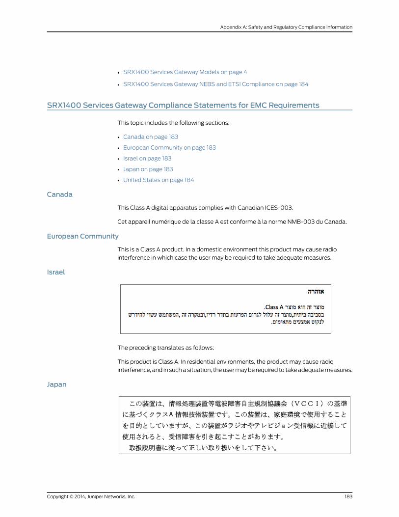
• SRX1400 Services Gateway Models on page 4
• SRX1400 Services Gateway NEBS and ETSI Compliance on page 184
SRX1400 Services Gateway Compliance Statements for EMC Requirements
This topic includes the following sections:
• Canada on page 183
• European Community on page 183
• Israel on page 183
• Japan on page 183
• United States on page 184
Canada
This Class A digital apparatus complies with Canadian ICES-003.
Cet appareil numérique de la classe A est conforme à la norme NMB-003 du Canada.
European Community
This is a Class A product. In a domestic environment this product may cause radio
interference in which case the user may be required to take adequate measures.
Israel
The preceding translates as follows:
This product is Class A. In residential environments, the product may cause radio
interference, and in such a situation, the user may be required to take adequate measures.
Japan
183Copyright © 2014, Juniper Networks, Inc.
Appendix A: Safety and Regulatory Compliance Information

The preceding translates as follows:
This is a Class A product based on the standard of the Voluntary Control Council for
Interference by Information Technology Equipment (VCCI). If this product is used near
a radio or television receiver in a domestic environment, it may cause radio interference.
Install and use the equipment according to the instruction manual.
United States
The services gateway has been tested and found to comply with the limits for a Class A
digital device of the FCC Rules. These limits are designed to provide reasonable protection
against harmful interference when the equipment is operated in a commercial
environment. This equipment generates, uses, and can radiate radio frequency energy
and, if not installed and used in accordance with the instruction manual, may cause
harmful interference to radio communications. Operation of this equipment in a residential
area is likely to cause harmful interference in which case the user will be required to
correct the interference at his own expense.
RelatedDocumentation
SRX1400 Services Gateway Agency Approvals on page 182•
• SRX1400 Services Gateway Description on page 3
• SRX1400 Services Gateway Models on page 4
• SRX1400 Services Gateway NEBS and ETSI Compliance on page 184
SRX1400 Services Gateway NEBS and ETSI Compliance
The SRX1400 Services Gateway, when installed and configured as described in this
documentation, meets the following NEBS and ETSI standards:
• GR-63-CORE
• ETSI 300019-2-1
• ETSI 300019-2-2
• ETSI 300019-2-3
• GR-1089-CORE
RelatedDocumentation
• SRX1400 Services Gateway Agency Approvals on page 182
• SRX1400 Services Gateway Description on page 3
• SRX1400 Services Gateway Models on page 4
Copyright © 2014, Juniper Networks, Inc.184
SRX1400 Services Gateway Hardware Guide

APPENDIX B
SRX1400 Services Gateway PowerGuidelines, Requirements, andSpecifications
This appendix includes the following topics:
• SRX1400 Services Gateway Grounding Specifications on page 185
• SRX1400 Services Gateway DC Power Specifications and Requirements on page 188
• SRX1400 Services Gateway AC Power Specifications and Requirements on page 192
SRX1400 Services Gateway Grounding Specifications
This topic includes the following sections:
• SRX1400 Services Gateway Chassis Grounding Point on page 185
• SRX1400 Services Gateway Grounding-Cable Lug Specification on page 186
• SRX1400 Services Gateway Grounding Cable Specification on page 187
SRX1400 Services Gateway Chassis Grounding Point
WARNING: Tomeet safety and electromagnetic interference (EMI)requirements and to ensure proper operation, youmust properly ground theservices gateway chassis before connecting power.
CAUTION: Before services gateway installationbegins, a licensedelectricianmust attach appropriate cable lugs to the grounding and power cables thatyou supply. A cablewith an incorrectly attached lug can damage the servicesgateway.
The services gateway chassis has one grounding point at the lower right corner of the
front panel. The grounding point consists of two threaded holes spaced 0.625-in.
(15.86-mm) apart (Figure 66 on page 186). The grounding point holes fit M5 screws. The
accessory box shipped with the services gateway includes the cable lug that attaches
185Copyright © 2014, Juniper Networks, Inc.

to the grounding cable and two M5 screws used to secure the grounding cable to the
services gateway grounding point.
Figure 66: Grounding Point on the SRX1400 Services Gateway
g033
542
To ground the services gateway, you must connect a grounding cable to earth ground
and then attach it to the chassis grounding point using the two screws provided.
NOTE: Additional grounding is provided to anAC-powered services gatewaywhen you plug its power supplies into grounded AC power receptacles.
RelatedDocumentation
SRX1400 Services Gateway Grounding-Cable Lug Specification on page 186•
• SRX1400 Services Gateway Grounding Cable Specification on page 187
• Grounding the SRX1400 Services Gateway on page 76
• SRX1400 Services Gateway Front Panel on page 15
SRX1400 Services Gateway Grounding-Cable Lug Specification
The cable attaches to the grounding cable (see Figure 67 on page 187) and two M5 screws
are used to secure the grounding cable to the grounding point.
Copyright © 2014, Juniper Networks, Inc.186
SRX1400 Services Gateway Hardware Guide

Figure 67: Grounding Cable Lug
Crimp area
6 AWG conductor
All measurements in inches
0.28diametereach hole
2.25
0.25 0.370.625 g001
188
0.55
End view
0.08
CAUTION: Before services gateway installationbegins, a licensedelectricianmust attach appropriate cable lugs to the grounding and power cables thatyou supply. A cablewith an incorrectly attached lug can damage the servicesgateway.
RelatedDocumentation
SRX1400 Services Gateway Chassis Grounding Point on page 185•
• SRX1400 Services Gateway Grounding Cable Specification on page 187
• Grounding the SRX1400 Services Gateway on page 76
• SRX1400 Services Gateway Front Panel on page 15
SRX1400 Services Gateway Grounding Cable Specification
The grounding cable that you provide must meet the specifications in Table 34 on page 187.
Table 34: Grounding Cable Specifications
Quantity and SpecificationCable Type
One 14-AWG (2.1 mm2), minimum 60°C wire, or as required bythe local code
Grounding
WARNING: Tomeet safety and electromagnetic interference (EMI)requirements and to ensure proper operation, youmust properly ground theservices gateway chassis before connecting power. See “Grounding theSRX1400 Services Gateway” on page 76 for instructions.
RelatedDocumentation
SRX1400 Services Gateway Chassis Grounding Point on page 185•
• SRX1400 Services Gateway Grounding-Cable Lug Specification on page 186
• Grounding the SRX1400 Services Gateway on page 76
• SRX1400 Services Gateway Front Panel on page 15
187Copyright © 2014, Juniper Networks, Inc.
Appendix B: SRX1400 Services Gateway Power Guidelines, Requirements, and Specifications

SRX1400 Services Gateway DC Power Specifications and Requirements
This topic includes the following sections:
• SRX1400 Services Gateway DC Power System Electrical Specifications on page 188
• SRX1400 Services Gateway DC Power Supply Electrical Specifications on page 188
• Power Requirements for DC-Powered SRX1400 Services Gateways on page 189
• SRX1400 Services Gateway DC Power Cable Specifications on page 191
SRX1400 Services Gateway DC Power System Electrical Specifications
Table 35 on page 188 lists the DC power system electrical specifications.
Table 35: DC Power System Electrical Specifications
SpecificationItem
Operating range: – 40 to – 72 VDCDC input voltage
10.1 A @ - 48 VDCDC system current rating
485 WMaximum DC input power
RelatedDocumentation
SRX1400 Services Gateway DC Power Supply Electrical Specifications on page 188•
• Power Requirements for DC-Powered SRX1400 Services Gateways on page 189
• SRX1400 Services Gateway DC Power Cable Specifications on page 191
• SRX1400 Services Gateway DC Power Supply on page 31
• Installing a DC Power Supply in the SRX1400 Services Gateway on page 69
SRX1400 Services Gateway DC Power Supply Electrical Specifications
Each DC power supply has a single DC input (-48 VDC and return) that requires a
dedicated 16 A (-48 VDC) circuit breaker. Table 36 on page 188 lists the DC power supply
electrical specifications.
Table 36: DC Power Supply Electrical Specifications
SpecificationParameter
1200 WMaximum output power
–40 to –72 VDCDC input voltage
30 A @ –48 VDCDC input current rating
Each DC power supply faceplate displays a single LED to indicate the status of the power
supply (see Table 37 on page 189).
Copyright © 2014, Juniper Networks, Inc.188
SRX1400 Services Gateway Hardware Guide

Table 37: DC Power Supply LED
Indicated ConditionLED StatusColor
DC input voltage is present, and both main 12 V output and standby3.3 V output are enabled and healthy.
On steadilyGreen
DC input voltage is present, standby 3.3 V output is on, but the main12 V output is disabled. This condition usually indicates that the devicehas been powered off at the Power button on the SYSIOC front panel.It might also indicate that either the SYSIOC or the Routing Engine hasbeen removed from the services gateway.
Blinking
The power supply has detected one or more of the following faults:
• Power supply fan failure
• Power supply over-temperature condition
• Over-current or under-voltage condition on the standby 3.3V output
On steadilyRed
The power supply has detected one or more of the following faults:
• Under-voltage condition on the 12 V output
• Over-voltage condition on the 12 V output
• Over-current condition on the 12 V output
Blinking
RelatedDocumentation
SRX1400 Services Gateway DC Power System Electrical Specifications on page 188•
• Power Requirements for DC-Powered SRX1400 Services Gateways on page 189
• SRX1400 Services Gateway DC Power Cable Specifications on page 191
• SRX1400 Services Gateway DC Power Supply on page 31
• Installing a DC Power Supply in the SRX1400 Services Gateway on page 69
Power Requirements for DC-Powered SRX1400 Services Gateways
NOTE: If you plan to operate amaximally configured DC-powered servicesgateway, we recommend that you provision 16 A@ -48 VDC for the system.
If you do not plan to provision 16 A @ -48 VDC for the system, you can use the information
in Table 38 on page 190 and Table 39 on page 190 to calculate the power consumption @
-48 VDC, and thermal output for various hardware configurations.
Table 38 on page 190 lists the power requirements for base DC-powered devices operating
under typical voltage conditions.
189Copyright © 2014, Juniper Networks, Inc.
Appendix B: SRX1400 Services Gateway Power Guidelines, Requirements, and Specifications

Table 38: DC-Powered Base SystemRequirements
Power Requirement (Watts)DC Power Supply Configuration
210 W (approximate)Nonredundant configuration includes DC power supply,backplane, SYSIOC, Routing Engine, and fan tray.
222 W (approximate)Redundant configuration includes two DC power supplies,backplane, SYSIOC, Routing Engine, and fan tray.
NOTE: The power requirement values shown in Table 38 on page 190 are fora lightly loaded system. For a heavily loaded system, the contribution of thebase system to the overall system power requirement is lower, because thepower supply efficiency improves as the load increases. For a heavily loadedsystem, both the redundant and nonredundant base systems contributeapproximately 210W to the overall system power requirement.
NOTE: In the SRX1400 Services Gateways with 1-Gigabit Ethernet SystemI/O card, the base system power requirement is less by 5-6 watts than theSRX1400 devices with 10-Gigabit Ethernet System I/O card.
Table 39 on page 190 lists the power requirements for various hardware components
when the services gateway is operating under typical voltage conditions.
Table 39: Component DC Power Requirements
Power Requirement (Watts)Component
214 WNSPC
61 W (max.)IOC
Use the information in Table 38 on page 190 and Table 39 on page 190 to calculate power
consumption for various hardware configurations, input current from a different source
voltage, and thermal output, as shown in the following examples. These examples use
maximum values per IOC.
• Minimum DC-powered configuration:
Base device + 1 NSPC =210W+214W= 424W, 8.83 A@ -48 VDC
• Maximum DC-powered configuration:
Base device + 1 NSPC + 1 IOC =210W+ 214W+ 61W = 485W, 10.1A@ -48 VDC
• Input current from a DC source other than -48 VDC (based on maximum configuration;
applies to DC power supply only):
Copyright © 2014, Juniper Networks, Inc.190
SRX1400 Services Gateway Hardware Guide

(–54 VDC input) * (input current X) = (-48 VDC input) * (input current Y)54 * X = 48V * 10.1 AX = (48 * 10.1)/54 = 8.98 A
• Thermal output for maximally configured DC-powered services gateway:
Watts DC * 3.41 = BTU/hr485 * 3.41 = 1653.85 BTU/hr
RelatedDocumentation
SRX1400 Services Gateway DC Power System Electrical Specifications on page 188•
• SRX1400 Services Gateway DC Power Supply Electrical Specifications on page 188
• SRX1400 Services Gateway DC Power Cable Specifications on page 191
• SRX1400 Services Gateway DC Power Supply on page 31
• Installing a DC Power Supply in the SRX1400 Services Gateway on page 69
SRX1400 Services Gateway DC Power Cable Specifications
The DC power supply in slotP0must be powered by dedicated power feeds derived from
feed A, and the DC power supply in slot P1 must be powered by dedicated power feeds
derived from feed B. This configuration provides the commonly deployed A/B feed
redundancy for the system.
CAUTION: Youmust ensure that power connectionsmaintain the properpolarity. The power source cablesmight be labeled (+) and (–) to indicate
their polarity. There is no standard color coding for DC power cables. Thecolor coding used by the external DC power source at your site determinesthe color coding for the leads on the power cables that attach to the terminalstuds on each power supply.
WARNING: For field-wiring connections, use copper conductors only.
For other electrical safety information, see “General Electrical SafetyGuidelines andWarnings” on page 171
CAUTION: Powercordsandcablesmustnotblockaccess toservicesgatewaycomponents or cause a tripping hazard.
For a description of the DC power supply, see “SRX1400 Services Gateway DC Power
Supply” on page 31. For instructions on connecting the DC power and grounding cables
during initial installation, see “Connecting the SRX1400 Services Gateway to a DC Power
Supply” on page 80. For instructions on replacing a DC power cable, see “Replacing a DC
Power Supply on the SRX1400 Services Gateway” on page 139.
191Copyright © 2014, Juniper Networks, Inc.
Appendix B: SRX1400 Services Gateway Power Guidelines, Requirements, and Specifications

Table 40 on page 192 summarizes the specifications for the power cables, which you must
supply.
Table 40: DC Power Cable Specifications
Quantity and SpecificationCable Type
Eight 6-AWG (13.3 mm2), minimum 60°C wire, or as permitted bythe local code
Power
RelatedDocumentation
SRX1400 Services Gateway DC Power System Electrical Specifications on page 188•
• SRX1400 Services Gateway DC Power Supply Electrical Specifications on page 188
• Power Requirements for DC-Powered SRX1400 Services Gateways on page 189
• SRX1400 Services Gateway DC Power Supply on page 31
• Installing a DC Power Supply in the SRX1400 Services Gateway on page 69
SRX1400 Services Gateway AC Power Specifications and Requirements
This topic includes the following sections:
• SRX1400 Services Gateway AC Power System Electrical Specifications on page 192
• SRX1400 Services Gateway AC Power Supply Electrical Specifications on page 193
• Power Requirements for AC-Powered SRX1400 Services Gateways on page 193
• SRX1400 Services Gateway AC Power Cord Specifications on page 195
SRX1400 Services Gateway AC Power System Electrical Specifications
Table 41 on page 192 lists the AC power system electrical specifications.
Table 41: AC Power SystemSpecifications
SpecificationItem
Operating range: 100-127 V / 200-240 VAC input voltage
47 – 63 HzAC input line frequency
5 A at 100 VAC
2.5 A at 100 VAC
AC system current rating
485 W at 100 VACMaximum AC input power
RelatedDocumentation
SRX1400 Services Gateway AC Power Supply Electrical Specifications on page 193•
• SRX1400 Services Gateway AC Power Cord Specifications on page 195
• Power Requirements for AC-Powered SRX1400 Services Gateways on page 193
Copyright © 2014, Juniper Networks, Inc.192
SRX1400 Services Gateway Hardware Guide

• SRX1400 Services Gateway AC Power Supply on page 30
• Connecting the SRX1400 Services Gateway to an AC Power Supply on page 77
SRX1400 Services Gateway AC Power Supply Electrical Specifications
Table 42 on page 193 lists the electrical specifications for the services gateway AC power
supply.
Table 42: AC Power Supply Electrical Specifications
SpecificationItem
1000 WMaximum output power
Operating range: 100-127 VAC / 200-240 VACAC input voltage
47 – 63 HzAC input line frequency
13.0 A (maximum) at 100 VAC
6.5 A (maximum) at 200 VAC
AC input current rating
RelatedDocumentation
SRX1400 Services Gateway AC Power System Electrical Specifications on page 192•
• SRX1400 Services Gateway AC Power Cord Specifications on page 195
• Power Requirements for AC-Powered SRX1400 Services Gateways on page 193
• SRX1400 Services Gateway AC Power Supply on page 30
• Connecting the SRX1400 Services Gateway to an AC Power Supply on page 77
Power Requirements for AC-Powered SRX1400 Services Gateways
NOTE: If you plan to operate amaximally configured AC-powered servicesgateway, we recommend that you provision 6 A at 240 VAC for the system.
If you do not plan to provision 6 A at 240 VAC for the system, you can use the information
in Table 43 on page 193 and Table 44 on page 194 to calculate power consumption for
various hardware configurations, and thermal output.
Table 43 on page 193 lists the power requirements for base AC-powered devices operating
under typical voltage conditions. It includes the efficiency for the AC power supplies.
Table 43: Base SystemAC Power Requirements
Power Requirement (Watts)Component
210 W (approximate)Nonredundant configuration includes AC power supply,backplane, SYSIOC, Routing Engine, and the fan tray.
193Copyright © 2014, Juniper Networks, Inc.
Appendix B: SRX1400 Services Gateway Power Guidelines, Requirements, and Specifications

Table 43: Base SystemAC Power Requirements (continued)
Power Requirement (Watts)Component
222 W (approximate)Redundant configuration includes two AC power supplies,backplane, SYSIOC, Routing Engine, and the fan tray.
NOTE: The power requirement values shown in Table 43 on page 193 are fora lightly loaded system. For a heavily loaded system, the contribution of thebase system to the overall system power requirement is lower, because thepower supply efficiency improves as the load increases. For a heavily loadedsystem, both the redundant and nonredundant base systems contributeapproximately 210W to the overall system power requirement.
NOTE: In SRX1400 Services Gateways with 1-Gigabit Ethernet System I/Ocard, the base system power requirement is less by 5 to 6 watts than thebase system power requirement for the SRX1400 devices with 10-GigabitEthernet System I/O card.
Table 44 on page 194 lists the power requirements for various hardware components
when the services gateway is operating under typical voltage conditions.
Table 44: Component AC Power Requirements
Power Requirement (Watts)Component
214 WNSPC
61 W (max.)IOC
Copyright © 2014, Juniper Networks, Inc.194
SRX1400 Services Gateway Hardware Guide
Use the information in Table 43 on page 193 and Table 44 on page 194 to calculate power
consumption for various hardware configurations, input current from a different source
voltage, and thermal output, as shown in the following examples. These examples use
maximum values per IOC.
Typical power consumption for AC-powered devices:
• Minimum AC-powered configuration:
Base device + 1 NSPC =210W+ 214W= 424W
• Maximum AC-powered configuration:
Base device + 1NSPC + 1 IOC =210W+ 214W+ 61W = 485W
• Typical system thermal output (based on maximally configured AC-powered services
gateway at 110 V input):
Watts * 3.41 = BTU/hr485W * 3.41 = 1653.85 BTU/hr
RelatedDocumentation
SRX1400 Services Gateway AC Power Supply Electrical Specifications on page 193•
• SRX1400 Services Gateway AC Power System Electrical Specifications on page 192
• SRX1400 Services Gateway AC Power Cord Specifications on page 195
• SRX1400 Services Gateway AC Power Supply on page 30
• Connecting the SRX1400 Services Gateway to an AC Power Supply on page 77
SRX1400 Services Gateway AC Power Cord Specifications
Each AC power supply has a single AC appliance inlet located on the power supply that
requires a dedicated AC power feed and a dedicated 15 A (250 VAC) circuit breaker. Most
sites distribute power through a main conduit that leads to frame-mounted power
distribution panels, one of which can be located at the top of the rack that houses the
device. An AC power cord connects each power supply to the power distribution panel.
Locate the power cord or cords with the type of plug appropriate for your geographical
location to connect the device to AC power using the model number.
The services gateway uses detachable AC power cords with C13 appliance couplers at
the female end as described by International Electrotechnical Commission (IEC) standard
60320. The plug at the male end of the power cord fits into the power source receptacle
that is standard for your geographical location.
Table 45 on page 196 provides specifications and Figure 68 on page 196 depicts the plug
on the AC power cord provided for each country or region.
195Copyright © 2014, Juniper Networks, Inc.
Appendix B: SRX1400 Services Gateway Power Guidelines, Requirements, and Specifications

Table 45: AC Power Cord Specifications
Plug TypeElectrical SpecificationModel NumberCountry
AS/NZ 3112–1993250 VAC, 10 A, 50 HzCBL-JX-PWR-AUAustralia
GB2099.1 1996 andGB1002 1996(CH1-10P)
250 VAC, 10 A, 50 HzCBL-JX-PWR-CHChina
CEE (7) VII250 VAC, 10 A, 50 HzCBL-JX-PWR-EUEurope (exceptItaly and UnitedKingdom)
CEI 23–16/VII250 VAC, 10 A, 50 HzCBL-JX-PWR-ITItaly
JIS 8303125 VAC, 12 A, 50 Hz or 60Hz
CBL-JX-PWR-JPJapan
NEMA 5-15125 VAC, 10 A, 60 HzCBL-JX-PWR-USNorth America
BS 1363A250 VAC, 10 A, 50 HzCBL-JX-PWR-UKUnited Kingdom
Figure 68: AC Plug Types
WARNING: The AC power cord for the services gateway is intended for usewith the SRX1400 Services Gateway only and not for any other devices.
WARNING: The attached power cable is only for this product. Do not use thecable for another product.
NOTE: In North America, AC power cordsmust not exceed approximately14.75 ft (4.5 m) in length, to comply with National Electrical Code (NEC)Sections 400-8 (NFPA 75, 5-2.2) and 210-52, and Canadian Electrical Code(CEC)Section4-010(3).YoucanorderACpowercords thatare incompliance.
For information about the AC power supply, including a description of components, see
“SRX1400 Services Gateway AC Power Supply” on page 30. For instructions on connecting
the power cord during initial installation, see “Connecting the SRX1400 Services Gateway
to an AC Power Supply” on page 77. For instructions on replacing the AC power cables,
see “Replacing an AC Power Supply on the SRX1400 Services Gateway” on page 137.
Copyright © 2014, Juniper Networks, Inc.196
SRX1400 Services Gateway Hardware Guide

RelatedDocumentation
• SRX1400 Services Gateway AC Power Supply Electrical Specifications on page 193
• SRX1400 Services Gateway AC Power System Electrical Specifications on page 192
• Power Requirements for AC-Powered SRX1400 Services Gateways on page 193
• SRX1400 Services Gateway AC Power Supply on page 30
• Connecting the SRX1400 Services Gateway to an AC Power Supply on page 77
197Copyright © 2014, Juniper Networks, Inc.
Appendix B: SRX1400 Services Gateway Power Guidelines, Requirements, and Specifications

Copyright © 2014, Juniper Networks, Inc.198
SRX1400 Services Gateway Hardware Guide

APPENDIX C
Cable andWire Guidelines for theSRX1400 Services Gateway Hardware
This appendix includes the following topics:
• SRX1400 Services Gateway Electrical Wiring Guidelines on page 199
• SRX1400 Services Gateway Network Cable Guidelines on page 200
SRX1400 Services Gateway ElectricalWiring Guidelines
This topic includes the following sections:
• Distance Limitations for Signaling for the SRX1400 Services Gateway on page 199
• Radio Frequency Interference for the SRX1400 Services Gateway on page 199
• Electromagnetic Compatibility for the SRX1400 Services Gateway on page 199
Distance Limitations for Signaling for the SRX1400 Services Gateway
Improperly installed wires can emit radio interference. In addition, the potential for damage
from lightning strikes increases if wires exceed recommended distances, or if wires pass
between buildings. The electromagnetic pulse (EMP) caused by lightning can damage
unshielded conductors and destroy electronic devices. If your site has previously
experienced such problems, you might want to consult experts in electrical surge
suppression and shielding
Radio Frequency Interference for the SRX1400 Services Gateway
You can reduce or eliminate the emission of radio frequency interference (RFI) from your
site wiring by using twisted-pair cable with a good distribution of grounding conductors.
If you must exceed the recommended distances, use a high-quality twisted-pair cable
with one ground conductor for each data signal when applicable.
Electromagnetic Compatibility for the SRX1400 Services Gateway
If your site is susceptible to problems with electromagnetic compatibility (EMC),
particularly from lightning or radio transmitters, you might want to seek expert advice.
Strong sources of electromagnetic interference (EMI) can destroy the signal drivers and
receivers in the services gateway and conduct power surges over the lines into the
199Copyright © 2014, Juniper Networks, Inc.

equipment, resulting in an electrical hazard. It is particularly important to provide a properly
grounded and shielded environment and to use electrical surge-suppression devices.
CAUTION: Certain ports on the device are designed for use as intrabuilding(within-the-building) interfaces only (Type 2 or Type 4 ports as described inGR-1089-CORE, Issue4)and require isolation fromtheexposedoutsideplant(OSP) cabling. To protect against lightening surges and commercial powerdisturbances, the intrabuilding ports must not bemetallically connected tointerfaces that connect to the OSP or its wiring. The intrabuilding ports onthe device are suitable for connection to intrabuilding or unexposed wiringor cabling only. Theaddition of primary protectors is not sufficient protectionfor connecting these interfacesmetallically to OSPwiring.
RelatedDocumentation
Signal Loss in Multimode and Single-Mode Fiber-Optic Cable for the SRX1400 Services
Gateway on page 200
•
• Attenuation and Dispersion in Fiber-Optic Cable for the SRX1400 Services Gateway
on page 201
• Calculating the Power Budget for Fiber-Optic Cable for the SRX1400 Services Gateway
on page 202
• Calculating the Power Margin for Fiber-Optic Cable for the SRX1400 Services Gateway
on page 202
SRX1400 Services Gateway Network Cable Guidelines
This topic includes the following sections:
• Signal Loss in Multimode and Single-Mode Fiber-Optic Cable for the SRX1400 Services
Gateway on page 200
• Attenuation and Dispersion in Fiber-Optic Cable for the SRX1400 Services
Gateway on page 201
• Calculating the Power Budget for Fiber-Optic Cable for the SRX1400 Services
Gateway on page 202
• Calculating the Power Margin for Fiber-Optic Cable for the SRX1400 Services
Gateway on page 202
• Console Port Cable and Wire Specifications for the SRX1400 Services
Gateway on page 204
SignalLoss inMultimodeandSingle-ModeFiber-OpticCable for theSRX1400ServicesGateway
Multimode fiber is large enough in diameter to allow rays of light to reflect internally
(bounce off the walls of the fiber). Interfaces with multimode optics typically use LEDs
as light sources. LEDs are not coherent sources, however. They spray varying wavelengths
of light into the multimode fiber, which reflects the light at different angles. Light rays
travel in jagged lines through a multimode fiber, causing signal dispersion. When light
traveling in the fiber core radiates into the fiber cladding, higher-order mode loss (HOL)
Copyright © 2014, Juniper Networks, Inc.200
SRX1400 Services Gateway Hardware Guide

results. Together these factors limit the transmission distance of multimode fiber
compared to single-mode fiber.
Single-mode fiber is so small in diameter that rays of light can reflect internally through
one layer only. Interfaces with single-mode optics use lasers as light sources. Lasers
generate a single wavelength of light, which travels in a straight line through the
single-mode fiber. Compared with multimode fiber, single-mode fiber has higher
bandwidth and can carry signals for longer distances. It is consequently more expensive.
RelatedDocumentation
SRX1400 Services Gateway Electrical Wiring Guidelines on page 199•
• Attenuation and Dispersion in Fiber-Optic Cable for the SRX1400 Services Gateway
on page 201
• Calculating the Power Budget for Fiber-Optic Cable for the SRX1400 Services Gateway
on page 202
• Calculating the Power Margin for Fiber-Optic Cable for the SRX1400 Services Gateway
on page 202
Attenuation and Dispersion in Fiber-Optic Cable for the SRX1400 Services Gateway
Correct functioning of an optical data link depends on modulated light reaching the
receiver with enough power to be demodulated correctly. Attenuation is the reduction in
power of the light signal as it is transmitted. Attenuation is caused by passive media
components, such as cables, cable splices, and connectors. While attenuation is
significantly lower for optical fiber than for other media, it still occurs in both multimode
and single-mode transmission. An efficient optical data link must have enough light
available to overcome attenuation.
Dispersion is the spreading of the signal in time. The following two types of dispersion
can affect an optical data link:
• Chromatic dispersion—The spreading of the signal in time resulting from the different
speeds of light rays.
• Modal dispersion—The spreading of the signal in time resulting from the different
propagation modes in the fiber.
For multimode transmission, modal dispersion, rather than chromatic dispersion or
attenuation, usually limits the maximum bit rate and link length. For single-mode
transmission, modal dispersion is not a factor. However, at higher bit rates and over longer
distances, chromatic dispersion rather than modal dispersion limits maximum link length.
An efficient optical data link must have enough light to exceed the minimum power that
the receiver requires to operate within its specifications. In addition, the total dispersion
must be less than the limits specified for the type of link in Telcordia Technologies
document GR-253-CORE (Section 4.3) and International Telecommunications Union
(ITU) document G.957.
When chromatic dispersion is at the maximum allowed, its effect can be considered as
a power penalty in the power budget. The optical power budget must allow for the sum
201Copyright © 2014, Juniper Networks, Inc.
Appendix C: Cable and Wire Guidelines for the SRX1400 Services Gateway Hardware

of component attenuation, power penalties (including those from dispersion), and a
safety margin for unexpected losses.
RelatedDocumentation
SRX1400 Services Gateway Electrical Wiring Guidelines on page 199•
• Signal Loss in Multimode and Single-Mode Fiber-Optic Cable for the SRX1400 Services
Gateway on page 200
• Calculating the Power Budget for Fiber-Optic Cable for the SRX1400 Services Gateway
on page 202
• Calculating the Power Margin for Fiber-Optic Cable for the SRX1400 Services Gateway
on page 202
Calculating the Power Budget for Fiber-Optic Cable for the SRX1400 Services Gateway
To ensure that fiber-optic connections have sufficient power for correct operation, you
need to calculate the link's power budget, which is the maximum amount of power it
can transmit. When you calculate the power budget, you use a worst-case analysis to
provide a margin of error, even though all the parts of an actual system do not operate
at the worst-case levels. To calculate the worst-case estimate of power budget (PB),
you assume minimum transmitter power (PT) and minimum receiver sensitivity (P
R):
PB= P
T– P
R
The following hypothetical power budget equation uses values measured in decibels
(dB) and decibels referred to one milliwatt (dBm):
PB= P
T– P
R
PB
= –15 dBm – (–28 dBm)
PB
= 13 dB
RelatedDocumentation
SRX1400 Services Gateway Electrical Wiring Guidelines on page 199•
• Signal Loss in Multimode and Single-Mode Fiber-Optic Cable for the SRX1400 Services
Gateway on page 200
• Attenuation and Dispersion in Fiber-Optic Cable for the SRX1400 Services Gateway
on page 201
• Calculating the Power Margin for Fiber-Optic Cable for the SRX1400 Services Gateway
on page 202
Calculating the Power Margin for Fiber-Optic Cable for the SRX1400 Services Gateway
After calculating a link's power budget, you can calculate the power margin (PM
), which
represents the amount of power available after subtracting attenuation or link loss (LL)
from the power budget (PB). A worst-case estimate of P
Massumes maximum LL:
PM= P
B– LL
Copyright © 2014, Juniper Networks, Inc.202
SRX1400 Services Gateway Hardware Guide

APM
greater than zero indicates that the power budget is sufficient to operate the receiver.
Factors that can cause link loss include higher-order mode losses, modal and chromatic
dispersion, connectors, splices, and fiber attenuation. Table 46 on page 203 lists an
estimated amount of loss for the factors used in the following sample calculations. For
information about the actual amount of signal loss caused by equipment and other
factors, see your vendor documentation.
Table 46: Estimated Values for Factors That Cause Link Loss
Estimated Link-Loss ValueLink-Loss Factor
Single-mode—None
Multimode—0.5 dB
Higher-order mode losses
Single-mode—None
Multimode—None, if product of bandwidth and distanceis less than 500 MHz–km
Modal and chromatic dispersion
0.5 dBConnector
0.5 dBSplice
Single-mode—0.5 dB/km
Multimode—1 dB/km
Fiber attenuation
The following example uses the estimated values in Table 46 on page 203 to calculate
link loss (LL) for a 2 km-long multimode link with a power budget (PB) of 13 dB:
• Fiber attenuation for 2 km @ 1.0 dB/km= 2 dB
• Loss for five connectors @ 0.5 dB per connector = 5(0.5 dB) = 2.5 dB
• Loss for two splices @ 0.5 dB per splice =2(0.5 dB) = 1 dB
• Higher-order loss = 0.5 dB
• Clock recovery module = 1 dB
The power margin (PM
) is calculated as follows:
PM= P
B– LL
PM
= 13 dB – 2 km (1.0 dB/km) – 5 (0.5 dB) – 2 (0.5 dB) – 0.5 dB [HOL] – 1 dB [CRM]
PM
= 13 dB – 2 dB – 2.5 dB – 1 dB – 0.5 dB – 1 dB
PM
= 6 dB
The following sample calculation for an 8 km-long single-mode link with a power budget
(PB) of 13 dB uses the estimated values from Table 46 on page 203 to calculate link loss
(LL) as the sum of fiber attenuation (8 km @ 0.5 dB/km, or 4 dB) and loss for seven
203Copyright © 2014, Juniper Networks, Inc.
Appendix C: Cable and Wire Guidelines for the SRX1400 Services Gateway Hardware

connectors (0.5 dB per connector, or 3.5 dB). The power margin (PM
) is calculated as
follows:
PM
= PB
– LL
PM
= 13 dB – 8 km (0.5 dB/km) – 7 (0.5 dB)
PM
= 13 dB – 4 dB – 3.5 dB
PM
= 5.5 dB
In both examples, the calculated power margin is greater than zero, indicating that the
link has sufficient power for transmission and does not exceed the maximum receiver
input power.
RelatedDocumentation
SRX1400 Services Gateway Electrical Wiring Guidelines on page 199•
• Signal Loss in Multimode and Single-Mode Fiber-Optic Cable for the SRX1400 Services
Gateway on page 200
• Attenuation and Dispersion in Fiber-Optic Cable for the SRX1400 Services Gateway
on page 201
• Calculating the Power Budget for Fiber-Optic Cable for the SRX1400 Services Gateway
on page 202
Console Port Cable andWire Specifications for the SRX1400 Services Gateway
Table 47 on page 204 lists the specifications for the cable that connects aCONSOLEport
on the SYSIOC to a management console.
Table 47: Cable andWire Specifications for Routing EngineManagementand Alarm Interfaces
ReceptacleMaximumLengthCable/WireSupplied
CableSpecificationPort
RJ-45/DB-9male
6 ft (1.83 m)One 6-ft (1.83-m)length withRJ-45/DB-9connectors
RS-232 (EIA-232)serial cable
SYSIOC console orRouting Engineauxiliary interface
RelatedDocumentation
• SRX1400 Services Gateway Electrical Wiring Guidelines on page 199
• Connecting the SRX1400 Services Gateway to a Management Console or an Auxiliary
Device on page 72
• Connecting the SRX1400 Services Gateway to a Network for Out-of-Band Management
on page 71
Copyright © 2014, Juniper Networks, Inc.204
SRX1400 Services Gateway Hardware Guide

APPENDIX D
Contacting Customer Support andReturning theSRX1400ServicesGatewayHardware
This appendix includes the following topics:
• Return Procedure for the SRX1400 Services Gateway on page 205
• Locating SRX1400 Services Gateway Component Serial Numbers on page 206
• Contacting Customer Support to Obtain Return Materials Authorization for the SRX1400
Services Gateway on page 210
• Packing an SRX1400 Services Gateway or a Component for Shipment on page 211
Return Procedure for the SRX1400 Services Gateway
If a problem cannot be resolved by the JTAC technician, a Return Materials Authorization
(RMA) is issued. This number is used to track the returned material at the factory and to
return repaired or new components to the customer as needed.
NOTE: Do not return any component to Juniper Networks, Inc. unless youhave first obtained an RMA number. Juniper Networks, Inc. reserves the rightto refuse shipments that do not have an RMA. Refused shipments will bereturned to the customer via collect freight.
For more information about return and repair policies, see the customer support Web
page at http://www.juniper.net/support/guidelines.html .
To return a services gateway or component to Juniper Networks for repair or replacement:
1. Determine the part number and serial number of the services gateway or component.
For the serial number locations of CFMs (SPCs, IOCs, and NPCs), see the SRX1400,
SRX3400, and SRX3600 Services Gateway Module Guide at www.juniper.net/techpubs/.
2. Obtain a Return Materials Authorization (RMA) number from JTAC.
205Copyright © 2014, Juniper Networks, Inc.

NOTE: Do not return the services gateway or any component to JuniperNetworksunlessyouhave firstobtainedanRMAnumber. JuniperNetworksreserves the right to refuse shipments that do not have an RMA. Refusedshipments are returned to the customer via collect freight.
3. Pack the services gateway or component for shipping.
For more information about return and repair policies, see the customer support webpage
at http://www.juniper.net/support/guidelines.html .
For product problems or technical support issues, open a support case using the Case
Manager link athttp://www.juniper.net/support/or call 1-888-314-JTAC (within the United
States) or 1-408-745-9500 (outside the United States).
RelatedDocumentation
Listing the SRX1400 Services Gateway Component Serial Numbers with the CLI on
page 206
•
• Information You Might Need to Supply to JTAC on page 210
• Contacting Customer Support on page 211
• Packing the SRX1400 Services Gateway for Shipment on page 212
• Packing SRX1400 Services Gateway Components for Shipment on page 213
Locating SRX1400 Services Gateway Component Serial Numbers
This topic includes the following sections:
• Listing the SRX1400 Services Gateway Component Serial Numbers with the
CLI on page 206
• Locating the SRX1400 Services Gateway Chassis Serial Number Label on page 207
• Locating the SRX1400 Services Gateway Network and Services Processing Card Serial
Number Label on page 208
• Locating the SRX1400 Services Gateway System I/O Card Serial Number
Label on page 208
• Locating the SRX1400 Services Gateway Power Supply Serial Number Label on page 209
• Locating the SRX1400 Services Gateway Fan Tray Number Label on page 209
Listing the SRX1400 Services Gateway Component Serial Numbers with the CLI
Before contacting Juniper Networks, Inc. to request a Return Materials Authorization
(RMA), you must find the serial number on the services gateway or component. To list
all of the device components and their serial numbers, enter the following command-line
interface (CLI) command:
user@host> show chassis hardware
Hardware inventory:Item Version Part number Serial number Description
Copyright © 2014, Juniper Networks, Inc.206
SRX1400 Services Gateway Hardware Guide

Chassis BH0310AA4416 SRX 1400Midplane REV 00 711-031012 AABA4416 SRX1k BackplanePEM 0 rev 06 740-020226 E182C1003Z06P AC Power SupplyCB 0 REV 16 750-032544 AAAY0804 SRX1K-RE-12-10 Routing Engine BUILTIN BUILTIN Routing Engine CPP BUILTIN BUILTIN Central PFE Processor Mezz REV 08 710-021035 AAAZ0730 SRX HD Mezzanine CardFPC 0 REV 00 750-031019 SRX1k 10GE SYSIO PIC 0 BUILTIN BUILTIN 6x 1GE RJ45 3x 1GE SFP3x 10GE SFP+ Xcvr 6 REV 02 740-013111 9101477 SFP-TFPC 1 REV 11 750-016077 AAAX7644 SRX3k SPC PIC 0 BUILTIN BUILTIN SPU Cp-FlowFPC 2 750-020317 TV3333 SRX3k 16xGE TX PIC 0 BUILTIN BUILTIN 16x 1GE-TXFPC 3 REV 13 750-017866 AAAN7996 SRX3k NPC PIC 0 BUILTIN BUILTIN NPC PICFan Tray -N/A- -N/A- -N/A- SRX 1400 Fan Tray
Most components also have a small rectangular serial number ID label attached to the
component body.
NOTE: To list all of the serial numbers of the NSPC, use the serial numberof FPC 1 or FPC 3 in the show chassis hardware command output.
RelatedDocumentation
Return Procedure for the SRX1400 Services Gateway on page 205•
• Information You Might Need to Supply to JTAC on page 210
• Contacting Customer Support on page 211
Locating the SRX1400 Services Gateway Chassis Serial Number Label
The chassis serial number is located on the side of the chassis as shown in
Figure 69 on page 207.
Figure 69: SRX1400 Services Gateway Chassis Serial Number Label
g033
549
SYS : BH2310AA0013
001f12e30800
207Copyright © 2014, Juniper Networks, Inc.
Appendix D: Contacting Customer Support and Returning the SRX1400 Services Gateway Hardware
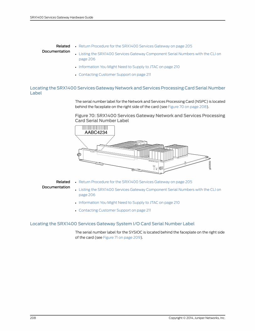
RelatedDocumentation
Return Procedure for the SRX1400 Services Gateway on page 205•
• Listing the SRX1400 Services Gateway Component Serial Numbers with the CLI on
page 206
• Information You Might Need to Supply to JTAC on page 210
• Contacting Customer Support on page 211
Locating theSRX1400ServicesGatewayNetworkandServicesProcessingCardSerialNumberLabel
The serial number label for the Network and Services Processing Card (NSPC) is located
behind the faceplate on the right side of the card (see Figure 70 on page 208).
Figure 70: SRX1400 Services Gateway Network and Services ProcessingCard Serial Number Label
g033
550
AABC4234
RelatedDocumentation
Return Procedure for the SRX1400 Services Gateway on page 205•
• Listing the SRX1400 Services Gateway Component Serial Numbers with the CLI on
page 206
• Information You Might Need to Supply to JTAC on page 210
• Contacting Customer Support on page 211
Locating the SRX1400 Services Gateway System I/O Card Serial Number Label
The serial number label for the SYSIOC is located behind the faceplate on the right side
of the card (see Figure 71 on page 209).
Copyright © 2014, Juniper Networks, Inc.208
SRX1400 Services Gateway Hardware Guide

Figure71: Locating theSRX1400ServicesGatewaySystemI/OCardSerialNumber Label
g033
551
AABC5530
RelatedDocumentation
Return Procedure for the SRX1400 Services Gateway on page 205•
• Listing the SRX1400 Services Gateway Component Serial Numbers with the CLI on
page 206
• Information You Might Need to Supply to JTAC on page 210
• Contacting Customer Support on page 211
Locating the SRX1400 Services Gateway Power Supply Serial Number Label
The serial number label for the AC and DC power supplies is located on the top of the
power supply (see Figure 72 on page 209).
Figure72:SRX1400ServicesGatewayPowerSupplySerialNumberLabel
g033
562
Serial number label
RelatedDocumentation
Return Procedure for the SRX1400 Services Gateway on page 205•
• Listing the SRX1400 Services Gateway Component Serial Numbers with the CLI on
page 206
• Information You Might Need to Supply to JTAC on page 210
• Contacting Customer Support on page 211
Locating the SRX1400 Services Gateway Fan Tray Number Label
The serial number label for the fan tray is located on the top of the fan tray (see
Figure 73 on page 210).
209Copyright © 2014, Juniper Networks, Inc.
Appendix D: Contacting Customer Support and Returning the SRX1400 Services Gateway Hardware

Figure 73: SRX1400 Fan Tray
g033
563
RelatedDocumentation
Return Procedure for the SRX1400 Services Gateway on page 205•
• Listing the SRX1400 Services Gateway Component Serial Numbers with the CLI on
page 206
• Information You Might Need to Supply to JTAC on page 210
• Contacting Customer Support on page 211
ContactingCustomerSupporttoObtainReturnMaterialsAuthorizationfortheSRX1400Services Gateway
This topic includes the following sections:
• Information You Might Need to Supply to JTAC on page 210
• Contacting Customer Support on page 211
Information YouMight Need to Supply to JTAC
When requesting support from JTAC by telephone, be prepared to provide the following
information:
• Your existing case number, if you have one
• Details of the failure or problem
• Type of activity being performed on the services gateway when the problem occurred
• Configuration data displayed by one or more show commands
• Your name, organization name, telephone number, fax number, and shipping address
RelatedDocumentation
Return Procedure for the SRX1400 Services Gateway on page 205•
• Listing the SRX1400 Services Gateway Component Serial Numbers with the CLI on
page 206
• Contacting Customer Support on page 211
Copyright © 2014, Juniper Networks, Inc.210
SRX1400 Services Gateway Hardware Guide

Contacting Customer Support
Once you have located the serial numbers of the services gateway or component, you
can return the services gateway or component for repair or replacement. For this, you
need to contact Juniper Networks Technical Assistance Center (JTAC).
You can contact JTAC 24 hours a day, 7 days a week, using any of the following methods:
• On the Web: Using the Case Manager link at http://www.juniper.net/support/
• By telephone:
• From the US and Canada: 1-888-314-JTAC
• From all other locations: 1-408-745-9500
NOTE: If contacting JTAC by telephone, enter your 11-digit case numberfollowed by the pound (#) key if this is an existing case, or press the star(*) key to be routed to the next available support engineer.
RelatedDocumentation
Return Procedure for the SRX1400 Services Gateway on page 205•
• Listing the SRX1400 Services Gateway Component Serial Numbers with the CLI on
page 206
• Information You Might Need to Supply to JTAC on page 210
Packing an SRX1400 Services Gateway or a Component for Shipment
This topic includes the following sections:
• Required Tools and Parts for Packing the SRX1400 Services Gateway on page 211
• Packing the SRX1400 Services Gateway for Shipment on page 212
• Packing SRX1400 Services Gateway Components for Shipment on page 213
Required Tools and Parts for Packing the SRX1400 Services Gateway
To remove the components from the services gateway or to remove the services gateway
from a rack, you need the following tools and parts:
• Blank panels to cover empty slots
• Electrostatic bag or antistatic mat for each component
• Electrostatic discharge (ESD) grounding wrist strap
• Flat-blade screwdriver, approximately 1/4 in. (6 mm)
• Phillips (+) screwdrivers, numbers 1 and 2
211Copyright © 2014, Juniper Networks, Inc.
Appendix D: Contacting Customer Support and Returning the SRX1400 Services Gateway Hardware

RelatedDocumentation
Return Procedure for the SRX1400 Services Gateway on page 205•
• Information You Might Need to Supply to JTAC on page 210
• Contacting Customer Support on page 211
• Packing the SRX1400 Services Gateway for Shipment on page 212
• Packing SRX1400 Services Gateway Components for Shipment on page 213
Packing the SRX1400 Services Gateway for Shipment
To pack the services gateway for shipment:
1. Retrieve the shipping carton and packing materials in which the services gateway was
originally shipped. If you do not have these materials, contact your Juniper Networks
representative about approved packaging materials.
2. Attach an ESD grounding strap to your bare wrist and connect the strap to the ESD
point on the chassis or to an outside ESD point if the services gateway is disconnected
from earth ground.
3. On the console or other management device connected to the services gateway, enter
CLI operational mode and issue the following command to shut down the services
gateway software:
user@host> request system halt
Wait until a message appears on the console confirming that the operating system
has halted.
4. Shut down power to the services gateway by pressing the Power button on the front
of the services gateway.
5. Disconnect power from the services gateway.
6. Remove the cables that connect to all external devices.
7. If the services gateway is installed in a rack, have one person support the weight of
the services gateway while another person unscrews and removes the mounting
screws.
8. Place the services gateway in the shipping carton.
9. Cover the services gateway with an ESD bag, and place the packing foam on top of
and around the services gateway.
10. Replace the accessory box on top of the packing foam.
11. Securely tape the box closed.
12. Write the Return Materials Authorization (RMA) number on the exterior of the box to
ensure proper tracking.
RelatedDocumentation
Return Procedure for the SRX1400 Services Gateway on page 205•
• Information You Might Need to Supply to JTAC on page 210
Copyright © 2014, Juniper Networks, Inc.212
SRX1400 Services Gateway Hardware Guide

• Contacting Customer Support on page 211
• Required Tools and Parts for Packing the SRX1400 Services Gateway on page 211
• Packing SRX1400 Services Gateway Components for Shipment on page 213
Packing SRX1400 Services Gateway Components for Shipment
Follow these guidelines for packing and shipping individual components of the services
gateway:
• When you return a component, make sure that it is adequately protected with packing
materials and packed so that the pieces are prevented from moving around inside the
carton.
• Use the original shipping materials if they are available.
• Place the individual component in an electrostatic bag.
• Write the Return Materials Authorization (RMA) number on the exterior of the box to
ensure proper tracking.
CAUTION: Do not stack any of the services gateway components duringpacking.
RelatedDocumentation
• Return Procedure for the SRX1400 Services Gateway on page 205
• Information You Might Need to Supply to JTAC on page 210
• Contacting Customer Support on page 211
• Required Tools and Parts for Packing the SRX1400 Services Gateway on page 211
• Packing the SRX1400 Services Gateway for Shipment on page 212
213Copyright © 2014, Juniper Networks, Inc.
Appendix D: Contacting Customer Support and Returning the SRX1400 Services Gateway Hardware

Copyright © 2014, Juniper Networks, Inc.214
SRX1400 Services Gateway Hardware Guide

PART 5
Index
• Index on page 217
215Copyright © 2014, Juniper Networks, Inc.

Copyright © 2014, Juniper Networks, Inc.216
SRX1400 Services Gateway Hardware Guide

Index
Symbols#, comments in configuration statements...................xiii
( ), in syntax descriptions.....................................................xiii
< >, in syntax descriptions...................................................xiii
[ ], in configuration statements.........................................xiii
{ }, in configuration statements........................................xiii
| (pipe), in syntax descriptions..........................................xiii
AAC power supply
installing............................................................................68
AC power supply cord
replacing..........................................................................139
accessory box
parts list.............................................................................45
removing............................................................................43
accident procedures, electrical.........................................171
agency approvals..................................................................182
air filter
replacing..........................................................................120
alarm
messages, list of...........................................................106
alarms
temperature, displaying.............................................107
attenuation in fiber-optic cable.......................................201
auxiliary port (for Routing Engine management)
cable
connection during initial installation..............72
specifications.......................................................204
Bbattery-handling warning..................................................165
braces, in configuration statements................................xiii
brackets
angle, in syntax descriptions......................................xiii
square, in configuration statements.......................xiii
Ccable
auxiliary or console port (for Routing Engine
management)
connecting during initial installation..............72
fiber-optic
attenuation............................................................201
dispersion...............................................................201
multimode and single-mode........................200
transmission distance, maximum...............200
wavelength ranges............................................200
chassis
alarm messages See alarm, messages
installing in rack..............................................................50
chromatic dispersion in fiber-optic cable....................201
class 1 laser warning.............................................................162
class 1 LED warning..............................................................162
CLI
command
to display chassis alarm messages.............106
commands
show chassis alarms..................................................106
comments, in configuration statements.......................xiii
compliance statements for EMC requirements
Canada.............................................................................183
European Community................................................183
Hebrew.............................................................................183
Japan.................................................................................183
United States.................................................................184
components
field replacement..........................................................115
components, packing for shipment...............................213
configuration
services gateway............................................................85
console device
serial port settings for...................................................72
console port (for Routing Engine management)
cable
connection during initial installation..............72
specifications.......................................................204
conventions
notice icons........................................................................xi
text and syntax.................................................................xii
cooling system
troubleshooting.............................................................107
curly braces, in configuration statements.....................xiii
customer support...................................................................xiv
contacting JTAC..............................................................xiv
customer support, contacting........................................206
217Copyright © 2014, Juniper Networks, Inc.

DDC power cables
replacing..........................................................................142
DC power supply
installing............................................................................69
dispersion in fiber-optic cable..........................................201
Eearthquakes
site preparation for.........................................................41
EIA rack standards.................................................................40
electrical
accident procedures.....................................................171
safety guidelines and warnings................................171
electrical specifications.............................................192, 193
EMC requirements
Canada.............................................................................183
European Community................................................183
Hebrew.............................................................................183
Japan.................................................................................183
United States.................................................................184
ETSI rack standards..............................................................40
Ffan tray
troubleshooting.............................................................107
fan trays
replacing............................................................................117
field-replaceable units
listed...................................................................................115
fire safety requirements......................................................154
font conventions......................................................................xii
front panel..................................................................................15
Ggrounding (electrical) specifications............................185
grounding cable
attachment point for..................................................185
connecting........................................................................76
lug specifications.........................................................186
specifications.................................................................187
guidelines, electrical safety.................................................171
Hhardware components
power requirements....................................................193
higher-order mode loss (HOL).......................................200
hot-swappable functionality of components,
description............................................................................115
Iinstallation
AC power, connecting...................................................77
DC power, connecting..................................................80
instructions warning....................................................156
parts received, verifying...............................................45
installation instructions
cable, auxiliary or console port (for Routing
Engine management)
during initial installation......................................72
installing
AC power supply............................................................68
DC power supply............................................................69
instructions
calculation
power requirements...........................................193
IOC..............................................................................................130
status, checking............................................................108
troubleshooting............................................................108
See also replacing
Jjewelry removal warning....................................................166
Juniper Technical Assistance Center (JTAC)................211
Llaser beam warning..............................................................163
laser safety guidelines..........................................................161
lightning activity warning...................................................168
link loss, calculating............................................................202
Mmodal dispersion in fiber-optic cable...........................201
mode loss, higher-order....................................................200
multimode fiber-optic cable See cable, fiber-optic
NNEBS..........................................................................................184
Network and Services Processing Card
replacing...........................................................................125
Network Processing Card
replacing...........................................................................127
notice icons.................................................................................xi
NPC.............................................................................................127
status, checking..............................................................112
See also replacing
NPCs
troubleshooting..............................................................112
Copyright © 2014, Juniper Networks, Inc.218
SRX1400 Services Gateway Hardware Guide

NSPC..........................................................................................125
See also replacing
NSPCs
troubleshooting.............................................................110
Ooperating temperature warning......................................169
Ppacking services gateway
components for shipment........................................213
for shipment...................................................................212
required tools and parts..............................................211
parentheses, in syntax descriptions................................xiii
parts
required for packing......................................................211
power
budget calculation for fiber-optic cable.............202
margin calculation......................................................202
requirements for hardware components............193
power supplies
AC electrical specifications.............................192, 193
power system
AC electrical specifications......................................192
troubleshooting..............................................................112
powering off the services gateway..................................82
powering on the services gateway....................................81
product disposal warning..................................................170
Qqualified personnel warning.............................................150
Rrack
securing to building........................................................41
size and strength required..........................................40
standards, EIA and ETSI.............................................40
rack requirements
mounting..........................................................................157
radiation from open port apertures warning..............164
repair policies........................................................................206
replacing
AC power supply cord.................................................139
air filter..............................................................................120
DC power supply cord.................................................142
fan trays.............................................................................117
IOC.....................................................................................130
NPC.....................................................................................127
NSPC.................................................................................125
Routing Engine...............................................................122
SPC....................................................................................128
SYSIOC.............................................................................133
restricted access area warning.........................................151
return materials authorization........................................205
return procedure...................................................................205
RMA See return materials authorization
Routing Engine
management ports
cable and wire specifications........................204
replacing...........................................................................122
Ssafety guidelines, laser.........................................................161
safety requirements
fire......................................................................................154
fire suppression equipment.....................................154
services gateway........................................................................3
configuration...................................................................85
front panel.........................................................................15
packing..............................................................................211
packing for shipment..................................................212
parts list.............................................................................45
returning.........................................................................205
unpacking..........................................................................43
Services Processing Card
replacing..........................................................................128
SFP and SFP+
installing...........................................................................134
shipment
packing services gateway..........................................212
packing the components...........................................213
show chassis alarms command.....................106, 107, 112
show chassis fpc command.............................................109
show chassis fpc detail command................................109
show chassis IOC command............................................108
show chassis IOC detail command...............................108
show chassis NPC command............................................112
show chassis NPC detail command...............................112
show chassis NSPC command........................................110
show chassis NSPC detail command............................110
show chassis SPC command.............................................111
show chassis SPC detail command.................................111
signal dispersion..................................................................200
single-mode fiber-optic cable See cable, fiber-optic
SPC.............................................................................................128
status, checking......................................................110, 111
See also replacing
219Copyright © 2014, Juniper Networks, Inc.
Index
SPCs
troubleshooting...............................................................111
specifications
cable
Routing Engine management ports............204
power
drawn by hardware components..................193
power system................................................................193
rack
connection to building structure......................41
size and strength...................................................40
SRX1400 Services Gateway..................................................3
support, requesting from JTAC.................................210, 211
support, technical See technical support
syntax conventions.................................................................xii
SYS I/O card
replacing...........................................................................133
SYSIOC .....................................................................................133
status, checking............................................................109
troubleshooting............................................................109
See also replacing
Ttechnical support
contacting JTAC..............................................................xiv
tools required for
packing..............................................................................211
transmission distances, fiber-optic cable..................200
troubleshooting
cooling system...............................................................107
fans....................................................................................107
IOC.....................................................................................108
NPC.....................................................................................112
power system..................................................................112
SPC..............................................................................110, 111
SYSIO card.....................................................................109
UU (rack unit).............................................................................40
unpacking the services gateway.......................................43
Wwarning
battery-handling...........................................................165
class 1 laser.....................................................................162
class 1 LED.......................................................................162
electrical safety guidelines.........................................171
installation instructions.............................................156
jewelry removal.............................................................166
laser beam......................................................................163
lightning activity...........................................................168
operating temperature...............................................169
product disposal...........................................................170
rack-mount requirements.........................................157
radiation from open apertures................................164
wavelength ranges supported by fiber-optic
cable.....................................................................................200
XXFP
installing...........................................................................134
Copyright © 2014, Juniper Networks, Inc.220
SRX1400 Services Gateway Hardware Guide