Embed Size (px)
Citation preview
USER GUIDE
BUSINESS SERIES48-Port 10/100 + 4-Port Gigabit Switch with WebView and Power over Ethernet
Model: SRW248G4P
�
Table of Contents
48-Port 10/100 + 4-Port G�gab�t Sw�tch w�th WebV�ew and Power over Ethernet
About This Guide 1Icon Descriptions . . . . . . . . . . . . . . . . . . . . . . . . . . . . . . . . . . . . . . . . . . . . . . 1
Online Resources . . . . . . . . . . . . . . . . . . . . . . . . . . . . . . . . . . . . . . . . . . . . . . 1
Copyright and Trademarks . . . . . . . . . . . . . . . . . . . . . . . . . . . . . . . . . . . . . . . . 1
Chapter 1: Introduction 2
Chapter 2: Product Overview 3Front Panel . . . . . . . . . . . . . . . . . . . . . . . . . . . . . . . . . . . . . . . . . . . . . . . . . . 3
Back Panel . . . . . . . . . . . . . . . . . . . . . . . . . . . . . . . . . . . . . . . . . . . . . . . . . . 4
Side Panel . . . . . . . . . . . . . . . . . . . . . . . . . . . . . . . . . . . . . . . . . . . . . . . . . . 4
Chapter 3: Connecting the Switch 5Overview . . . . . . . . . . . . . . . . . . . . . . . . . . . . . . . . . . . . . . . . . . . . . . . . . . . 5
Pre-Installation Considerations . . . . . . . . . . . . . . . . . . . . . . . . . . . . . . . . . . . . . 5
Fast Ethernet Considerations . . . . . . . . . . . . . . . . . . . . . . . . . . . . . . . . . . . 5
Full-Duplex Considerations . . . . . . . . . . . . . . . . . . . . . . . . . . . . . . . . . . . . 5
1000BASE-T Cable Requirements . . . . . . . . . . . . . . . . . . . . . . . . . . . . . . . . . 5
Positioning the Switch . . . . . . . . . . . . . . . . . . . . . . . . . . . . . . . . . . . . . . . 5
Placement Options . . . . . . . . . . . . . . . . . . . . . . . . . . . . . . . . . . . . . . . . . . . . 5
Desktop Placement . . . . . . . . . . . . . . . . . . . . . . . . . . . . . . . . . . . . . . . . . 6
Rack-Mount Placement . . . . . . . . . . . . . . . . . . . . . . . . . . . . . . . . . . . . . . . 6
Hardware Installation . . . . . . . . . . . . . . . . . . . . . . . . . . . . . . . . . . . . . . . . . . . 6
Uplinking the Switch . . . . . . . . . . . . . . . . . . . . . . . . . . . . . . . . . . . . . . . . . . . 6
Chapter 4: Configuration Using the Console Interface 7Overview . . . . . . . . . . . . . . . . . . . . . . . . . . . . . . . . . . . . . . . . . . . . . . . . . . . 7
Configuring the HyperTerminal Application . . . . . . . . . . . . . . . . . . . . . . . . . . . . . 7
Configuring the Switch through the Console Interface . . . . . . . . . . . . . . . . . . . . . . 8
Login . . . . . . . . . . . . . . . . . . . . . . . . . . . . . . . . . . . . . . . . . . . . . . . . . . . . . 8
Switch Main Menu . . . . . . . . . . . . . . . . . . . . . . . . . . . . . . . . . . . . . . . . . . . . . 8
System Configuration Menu . . . . . . . . . . . . . . . . . . . . . . . . . . . . . . . . . . . . 8
Port Status . . . . . . . . . . . . . . . . . . . . . . . . . . . . . . . . . . . . . . . . . . . . . . .12
Port Configuration . . . . . . . . . . . . . . . . . . . . . . . . . . . . . . . . . . . . . . . . . .12
PoE Configuration . . . . . . . . . . . . . . . . . . . . . . . . . . . . . . . . . . . . . . . . . .12
Chapter 5: Configuring the Switch 14Setup . . . . . . . . . . . . . . . . . . . . . . . . . . . . . . . . . . . . . . . . . . . . . . . . . . . . .14
Setup > Summary . . . . . . . . . . . . . . . . . . . . . . . . . . . . . . . . . . . . . . . . . .14
Setup > Network Settings . . . . . . . . . . . . . . . . . . . . . . . . . . . . . . . . . . . . .15
Setup > Time . . . . . . . . . . . . . . . . . . . . . . . . . . . . . . . . . . . . . . . . . . . . .16
Port Management . . . . . . . . . . . . . . . . . . . . . . . . . . . . . . . . . . . . . . . . . . . . .17
Port Management > Port Settings . . . . . . . . . . . . . . . . . . . . . . . . . . . . . . . .17
Port Management > Link Aggregation . . . . . . . . . . . . . . . . . . . . . . . . . . . . .18

��
Table of Contents
48-Port 10/100 + 4-Port G�gab�t Sw�tch w�th WebV�ew and Power over Ethernet
Port Management > LACP . . . . . . . . . . . . . . . . . . . . . . . . . . . . . . . . . . . . .19
Port Management > PoE Power Settings . . . . . . . . . . . . . . . . . . . . . . . . . . . .19
VLAN Management . . . . . . . . . . . . . . . . . . . . . . . . . . . . . . . . . . . . . . . . . . . .20
VLAN Management > Create VLAN . . . . . . . . . . . . . . . . . . . . . . . . . . . . . . .20
VLAN Management > Port Settings . . . . . . . . . . . . . . . . . . . . . . . . . . . . . . .20
VLAN Management > Ports to VLAN . . . . . . . . . . . . . . . . . . . . . . . . . . . . . . .21
VLAN Management > VLAN to Ports . . . . . . . . . . . . . . . . . . . . . . . . . . . . . . .21
Statistics . . . . . . . . . . . . . . . . . . . . . . . . . . . . . . . . . . . . . . . . . . . . . . . . . . .22
Statistics > RMON Statistics . . . . . . . . . . . . . . . . . . . . . . . . . . . . . . . . . . . .22
Statistics > RMON History . . . . . . . . . . . . . . . . . . . . . . . . . . . . . . . . . . . . .22
Statistics > RMON Alarms . . . . . . . . . . . . . . . . . . . . . . . . . . . . . . . . . . . . . .23
Statistics > RMON Events . . . . . . . . . . . . . . . . . . . . . . . . . . . . . . . . . . . . . .23
Statistics > Port Utilization . . . . . . . . . . . . . . . . . . . . . . . . . . . . . . . . . . . . .24
Statistics > 802 .1x Statistics . . . . . . . . . . . . . . . . . . . . . . . . . . . . . . . . . . . .24
ACL . . . . . . . . . . . . . . . . . . . . . . . . . . . . . . . . . . . . . . . . . . . . . . . . . . . . . .24
ACL > IP based ACL . . . . . . . . . . . . . . . . . . . . . . . . . . . . . . . . . . . . . . . . .25
ACL > MAC based ACL . . . . . . . . . . . . . . . . . . . . . . . . . . . . . . . . . . . . . . . .25
Security . . . . . . . . . . . . . . . . . . . . . . . . . . . . . . . . . . . . . . . . . . . . . . . . . . . .26
Security > ACL Binding . . . . . . . . . . . . . . . . . . . . . . . . . . . . . . . . . . . . . . .26
Security > Authentication Servers . . . . . . . . . . . . . . . . . . . . . . . . . . . . . . . .26
Security > 802 .1x Settings . . . . . . . . . . . . . . . . . . . . . . . . . . . . . . . . . . . . .27
Security > Ports Security . . . . . . . . . . . . . . . . . . . . . . . . . . . . . . . . . . . . . .28
Security > HTTPS Settings . . . . . . . . . . . . . . . . . . . . . . . . . . . . . . . . . . . . .29
Security > Management ACL . . . . . . . . . . . . . . . . . . . . . . . . . . . . . . . . . . .29
Security > SSH Settings . . . . . . . . . . . . . . . . . . . . . . . . . . . . . . . . . . . . . . .30
Security > SSH Host-Key Settings . . . . . . . . . . . . . . . . . . . . . . . . . . . . . . . . .30
QoS . . . . . . . . . . . . . . . . . . . . . . . . . . . . . . . . . . . . . . . . . . . . . . . . . . . . . .31
QoS > CoS Settings . . . . . . . . . . . . . . . . . . . . . . . . . . . . . . . . . . . . . . . . .31
QoS > Queue Settings . . . . . . . . . . . . . . . . . . . . . . . . . . . . . . . . . . . . . . . .32
QoS > DSCP Settings . . . . . . . . . . . . . . . . . . . . . . . . . . . . . . . . . . . . . . . .32
QoS > DiffServ Settings . . . . . . . . . . . . . . . . . . . . . . . . . . . . . . . . . . . . . . .33
QoS > DiffServ Port Binding . . . . . . . . . . . . . . . . . . . . . . . . . . . . . . . . . . . .35
QoS > Bandwidth . . . . . . . . . . . . . . . . . . . . . . . . . . . . . . . . . . . . . . . . . . .35
Spanning Tree . . . . . . . . . . . . . . . . . . . . . . . . . . . . . . . . . . . . . . . . . . . . . . . .35
Spanning Tree > STP Status . . . . . . . . . . . . . . . . . . . . . . . . . . . . . . . . . . . .36
Spanning Tree > Global STP . . . . . . . . . . . . . . . . . . . . . . . . . . . . . . . . . . . .36
Spanning Tree > STP Port Settings . . . . . . . . . . . . . . . . . . . . . . . . . . . . . . . .37
Spanning Tree > RSTP Port Settings . . . . . . . . . . . . . . . . . . . . . . . . . . . . . . .39
Spanning Tree > MSTP Properties . . . . . . . . . . . . . . . . . . . . . . . . . . . . . . . .40
Spanning Tree > MSTP Instance Settings . . . . . . . . . . . . . . . . . . . . . . . . . . . .40
Spanning Tree > MSTP Interface Settings . . . . . . . . . . . . . . . . . . . . . . . . . . .41
Multicast . . . . . . . . . . . . . . . . . . . . . . . . . . . . . . . . . . . . . . . . . . . . . . . . . . .42
Multicast > Global Settings . . . . . . . . . . . . . . . . . . . . . . . . . . . . . . . . . . . .43
���
Table of Contents
48-Port 10/100 + 4-Port G�gab�t Sw�tch w�th WebV�ew and Power over Ethernet
Multicast > Static Member Ports . . . . . . . . . . . . . . . . . . . . . . . . . . . . . . . . .43
Multicast > Static Router Ports . . . . . . . . . . . . . . . . . . . . . . . . . . . . . . . . . .44
Multicast > Member Ports Query . . . . . . . . . . . . . . . . . . . . . . . . . . . . . . . . .44
Multicast > Router Ports Query . . . . . . . . . . . . . . . . . . . . . . . . . . . . . . . . . .44
SNMP . . . . . . . . . . . . . . . . . . . . . . . . . . . . . . . . . . . . . . . . . . . . . . . . . . . . .44
SNMP > Global Parameters . . . . . . . . . . . . . . . . . . . . . . . . . . . . . . . . . . . . .45
SNMP > Views . . . . . . . . . . . . . . . . . . . . . . . . . . . . . . . . . . . . . . . . . . . . .46
SNMP > Group Profile . . . . . . . . . . . . . . . . . . . . . . . . . . . . . . . . . . . . . . . .46
SNMP > Group Membership . . . . . . . . . . . . . . . . . . . . . . . . . . . . . . . . . . . .47
SNMP > Communities . . . . . . . . . . . . . . . . . . . . . . . . . . . . . . . . . . . . . . . .47
SNMP > Notification Recipient . . . . . . . . . . . . . . . . . . . . . . . . . . . . . . . . . .48
Admin . . . . . . . . . . . . . . . . . . . . . . . . . . . . . . . . . . . . . . . . . . . . . . . . . . . . .48
Admin > User Authentication . . . . . . . . . . . . . . . . . . . . . . . . . . . . . . . . . . .48
Admin > Forwarding Database . . . . . . . . . . . . . . . . . . . . . . . . . . . . . . . . . .49
Admin > Log . . . . . . . . . . . . . . . . . . . . . . . . . . . . . . . . . . . . . . . . . . . . . .50
Admin > Port Mirroring . . . . . . . . . . . . . . . . . . . . . . . . . . . . . . . . . . . . . . .51
Admin > Cable Test . . . . . . . . . . . . . . . . . . . . . . . . . . . . . . . . . . . . . . . . .52
Admin > Ping . . . . . . . . . . . . . . . . . . . . . . . . . . . . . . . . . . . . . . . . . . . . .52
Admin > Save Configuration . . . . . . . . . . . . . . . . . . . . . . . . . . . . . . . . . . . .52
Admin > Jumbo Frame . . . . . . . . . . . . . . . . . . . . . . . . . . . . . . . . . . . . . . .53
Admin > Firmware Upgrade . . . . . . . . . . . . . . . . . . . . . . . . . . . . . . . . . . . .53
Admin > HTTP Upgrade . . . . . . . . . . . . . . . . . . . . . . . . . . . . . . . . . . . . . .53
Admin > Reboot . . . . . . . . . . . . . . . . . . . . . . . . . . . . . . . . . . . . . . . . . . .54
Admin > Factory Default . . . . . . . . . . . . . . . . . . . . . . . . . . . . . . . . . . . . . .54
Appendix A: About Gigabit Ethernet and Fiber Optic Cabling 55Gigabit Ethernet . . . . . . . . . . . . . . . . . . . . . . . . . . . . . . . . . . . . . . . . . . . . . .55
Fiber Optic Cabling . . . . . . . . . . . . . . . . . . . . . . . . . . . . . . . . . . . . . . . . . . . .55
Appendix B: Glossary 56
Appendix C: Specifications 60
Appendix D: Warranty and Regulatory Information 62Limited Warranty . . . . . . . . . . . . . . . . . . . . . . . . . . . . . . . . . . . . . . . . . . . . . .62
FCC Statement . . . . . . . . . . . . . . . . . . . . . . . . . . . . . . . . . . . . . . . . . . . . . . .63
Safety Notices . . . . . . . . . . . . . . . . . . . . . . . . . . . . . . . . . . . . . . . . . . . . . . . .63
Industry Canada (Canada) . . . . . . . . . . . . . . . . . . . . . . . . . . . . . . . . . . . . . . . .63
IC Statement . . . . . . . . . . . . . . . . . . . . . . . . . . . . . . . . . . . . . . . . . . . . . . . .63
Règlement d’Industry Canada . . . . . . . . . . . . . . . . . . . . . . . . . . . . . . . . . . . . .63
EC Declaration of Conformity (Europe) . . . . . . . . . . . . . . . . . . . . . . . . . . . . . . . .63
Appendix E: Contact Information 68
1
About This Guide
48-Port 10/100 + 4-Port G�gab�t Sw�tch w�th WebV�ew and Power over Ethernet
About Th�s Gu�de
Icon DescriptionsWhile reading through the User Guide you may encounter various icons designed to call attention to a specific item . Below is a description of these icons:
NOTE: This checkmark indicates that there is a note of interest and is something that you should pay special attention to while using the product .
WARNING: This exclamation point indicates that there is a caution or warning and it is something that could damage your property or product .
WEB: This globe icon indicates a noteworthy website address or e-mail address .
Online ResourcesMost web browsers allow you to enter the web address without adding the http:// in front of the address . This User Guide will refer to websites without including http:// in front of the address . Some older web browsers may require you to add it .
Resource Webs�te
Linksys www .linksys .com
Linksys International www .linksys .com/international
Glossary www .linksys .com/glossary
Network Security www .linksys .com/security
Copyright and TrademarksSpecifications are subject to change without notice . Linksys is a registered trademark or trademark of Cisco Systems, Inc . and/or its affiliates in the U .S . and certain other countries . Copyright © 2006 Cisco Systems, Inc . All rights reserved . Other brands and product names are trademarks or registered trademarks of their respective holders .
�
Introduction
48-Port 10/100 + 4-Port G�gab�t Sw�tch w�th WebV�ew and Power over Ethernet
Chapter 1
Chapter 1: Introduct�onThank you for choosing the 48-Port 10/100 + 4-Port Gigabit Switch with WebView and Power over Ethernet . This Switch will allow you to network better than ever . The 48-Port 10/100 + 4-Port Gigabit Switch with WebView delivers non-blocking, wire speed switching for your 10 and 100 megabit network clients, plus multiple options for connecting to your network backbone . Forty-eight 10/100 ports wire up your workstations, while the four integrated 10/100/1000 ports connect to other switches and the backbone at Gigabit speeds . The miniGBIC ports allow future expansion through alternate transmission media like optical fiber .
All of the 10/100 ports on the Switch support pre-standard and IEEE 802 .3af standard (802 .3af ) Power over Ethernet (PoE) capabilities . Each port can detect connected pre-standard and 802 .3af-compliant network devices, such as IP phones or wireless access points, and automatically supply the required DC power .
The Switch can provide DC power to a wide range of connected devices, eliminating the need for an additional power source and cutting down on the amount of cables attached to each device . Once configured to supply power, an automatic detection process is initialized by the Switch that is authenticated by a PoE signature from the connected device . Detection and authentication prevent damage to non-PoE devices .
The Switch features WebView monitoring and configuration via your web browser, making it easy to manage the 256 VLANs and up to 8 trunking groups . Or if you prefer, you can use the integrated console port to configure the Switch . The non-blocking, wire-speed switching forwards packets as fast as your network can deliver them .
All ports have automatic MDI/MDI-X crossover detection . Each port independently and automatically negotiates the best speed and whether to run in half- or full-duplex mode . Head-of-line blocking prevention keeps your high-speed clients from bogging down in lower-speed traffic and fast store-and-forward switching prevents damaged packets from being passed on into the network .
Use the instructions in this User Guide to help you connect the Switch, set it up, and configure it to bridge your different networks . These instructions should be all you need to get the most out of the 48-Port 10/100 + 4-Port Gigabit Switch with WebView and Power over Ethernet .
�
Product Overview
48-Port 10/100 + 4-Port G�gab�t Sw�tch w�th WebV�ew and Power over Ethernet
Chapter �
Chapter �: Product Overv�ew
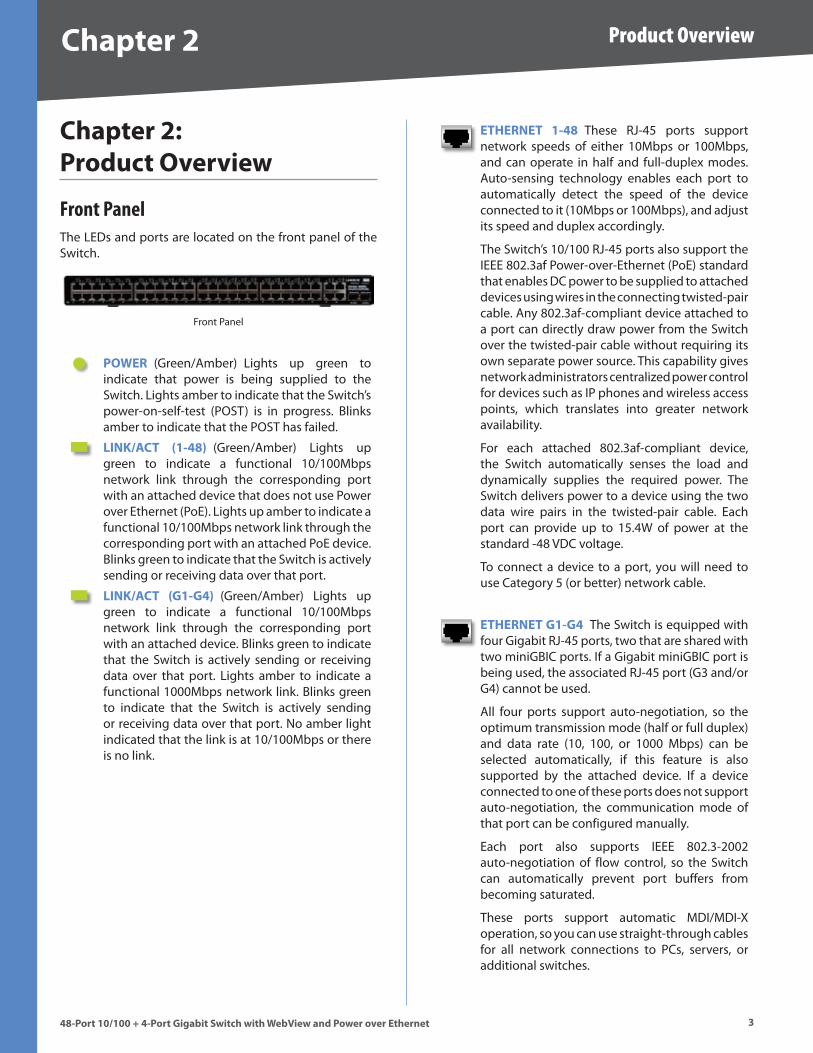
Front PanelThe LEDs and ports are located on the front panel of the Switch .
Front Panel
POWER (Green/Amber) Lights up green to indicate that power is being supplied to the Switch . Lights amber to indicate that the Switch’s power-on-self-test (POST) is in progress . Blinks amber to indicate that the POST has failed .
LINK/ACT (1-48) (Green/Amber) Lights up green to indicate a functional 10/100Mbps network link through the corresponding port with an attached device that does not use Power over Ethernet (PoE) . Lights up amber to indicate a functional 10/100Mbps network link through the corresponding port with an attached PoE device . Blinks green to indicate that the Switch is actively sending or receiving data over that port .
LINK/ACT (G1-G4) (Green/Amber) Lights up green to indicate a functional 10/100Mbps network link through the corresponding port with an attached device . Blinks green to indicate that the Switch is actively sending or receiving data over that port . Lights amber to indicate a functional 1000Mbps network link . Blinks green to indicate that the Switch is actively sending or receiving data over that port . No amber light indicated that the link is at 10/100Mbps or there is no link .
ETHERNET 1-48 These RJ-45 ports support network speeds of either 10Mbps or 100Mbps, and can operate in half and full-duplex modes . Auto-sensing technology enables each port to automatically detect the speed of the device connected to it (10Mbps or 100Mbps), and adjust its speed and duplex accordingly .
The Switch’s 10/100 RJ-45 ports also support the IEEE 802 .3af Power-over-Ethernet (PoE) standard that enables DC power to be supplied to attached devices using wires in the connecting twisted-pair cable . Any 802 .3af-compliant device attached to a port can directly draw power from the Switch over the twisted-pair cable without requiring its own separate power source . This capability gives network administrators centralized power control for devices such as IP phones and wireless access points, which translates into greater network availability .
For each attached 802 .3af-compliant device, the Switch automatically senses the load and dynamically supplies the required power . The Switch delivers power to a device using the two data wire pairs in the twisted-pair cable . Each port can provide up to 15 .4W of power at the standard -48 VDC voltage .
To connect a device to a port, you will need to use Category 5 (or better) network cable .
ETHERNET G1-G4 The Switch is equipped with four Gigabit RJ-45 ports, two that are shared with two miniGBIC ports . If a Gigabit miniGBIC port is being used, the associated RJ-45 port (G3 and/or G4) cannot be used .
All four ports support auto-negotiation, so the optimum transmission mode (half or full duplex) and data rate (10, 100, or 1000 Mbps) can be selected automatically, if this feature is also supported by the attached device . If a device connected to one of these ports does not support auto-negotiation, the communication mode of that port can be configured manually .
Each port also supports IEEE 802 .3-2002 auto-negotiation of flow control, so the Switch can automatically prevent port buffers from becoming saturated .
These ports support automatic MDI/MDI-X operation, so you can use straight-through cables for all network connections to PCs, servers, or additional switches .
4
Product Overview
48-Port 10/100 + 4-Port G�gab�t Sw�tch w�th WebV�ew and Power over Ethernet
Chapter �
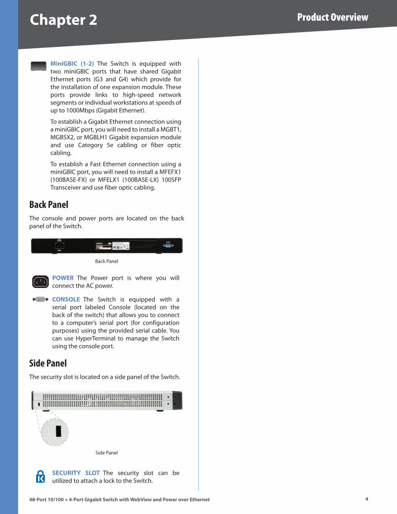
M�n�GBIC (1-�) The Switch is equipped with two miniGBIC ports that have shared Gigabit Ethernet ports (G3 and G4) which provide for the installation of one expansion module . These ports provide links to high-speed network segments or individual workstations at speeds of up to 1000Mbps (Gigabit Ethernet) .
To establish a Gigabit Ethernet connection using a miniGBIC port, you will need to install a MGBT1, MGBSX2, or MGBLH1 Gigabit expansion module and use Category 5e cabling or fiber optic cabling .
To establish a Fast Ethernet connection using a miniGBIC port, you will need to install a MFEFX1 (100BASE-FX) or MFELX1 (100BASE-LX) 100SFP Transceiver and use fiber optic cabling .
Back PanelThe console and power ports are located on the back panel of the Switch .
Back Panel
POWER The Power port is where you will connect the AC power .
CONSOLE The Switch is equipped with a serial port labeled Console (located on the back of the switch) that allows you to connect to a computer’s serial port (for configuration purposes) using the provided serial cable . You can use HyperTerminal to manage the Switch using the console port .
Side PanelThe security slot is located on a side panel of the Switch .
Side Panel
SECURITY SLOT The security slot can be utilized to attach a lock to the Switch .
�
Connecting the Switch
48-Port 10/100 + 4-Port G�gab�t Sw�tch w�th WebV�ew and Power over Ethernet
Chapter �
Chapter �: Connect�ng the Sw�tch
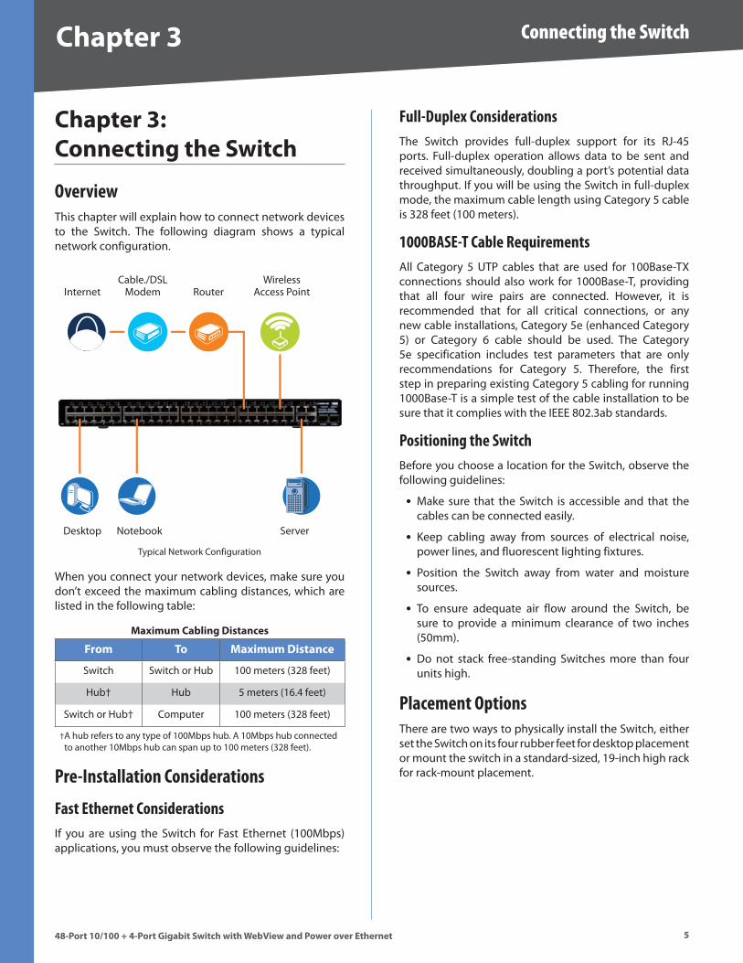
OverviewThis chapter will explain how to connect network devices to the Switch . The following diagram shows a typical network configuration .
InternetCable ./DSL
Modem RouterWireless
Access Point
Desktop Notebook Server
Typical Network Configuration
When you connect your network devices, make sure you don’t exceed the maximum cabling distances, which are listed in the following table:
Max�mum Cabl�ng D�stances
From To Max�mum D�stance
Switch Switch or Hub 100 meters (328 feet)
Hub† Hub 5 meters (16 .4 feet)
Switch or Hub† Computer 100 meters (328 feet)
A hub refers to any type of 100Mbps hub . A 10Mbps hub connected to another 10Mbps hub can span up to 100 meters (328 feet) .
†
Pre-Installation Considerations
Fast Ethernet ConsiderationsIf you are using the Switch for Fast Ethernet (100Mbps) applications, you must observe the following guidelines:
Full-Duplex ConsiderationsThe Switch provides full-duplex support for its RJ-45 ports . Full-duplex operation allows data to be sent and received simultaneously, doubling a port’s potential data throughput . If you will be using the Switch in full-duplex mode, the maximum cable length using Category 5 cable is 328 feet (100 meters) .
1000BASE-T Cable RequirementsAll Category 5 UTP cables that are used for 100Base-TX connections should also work for 1000Base-T, providing that all four wire pairs are connected . However, it is recommended that for all critical connections, or any new cable installations, Category 5e (enhanced Category 5) or Category 6 cable should be used . The Category 5e specification includes test parameters that are only recommendations for Category 5 . Therefore, the first step in preparing existing Category 5 cabling for running 1000Base-T is a simple test of the cable installation to be sure that it complies with the IEEE 802 .3ab standards .
Positioning the SwitchBefore you choose a location for the Switch, observe the following guidelines:
Make sure that the Switch is accessible and that the cables can be connected easily .
Keep cabling away from sources of electrical noise, power lines, and fluorescent lighting fixtures .
Position the Switch away from water and moisture sources .
To ensure adequate air flow around the Switch, be sure to provide a minimum clearance of two inches (50mm) .
Do not stack free-standing Switches more than four units high .
Placement OptionsThere are two ways to physically install the Switch, either set the Switch on its four rubber feet for desktop placement or mount the switch in a standard-sized, 19-inch high rack for rack-mount placement .
•
•
•
•
•
�
Connecting the Switch
48-Port 10/100 + 4-Port G�gab�t Sw�tch w�th WebV�ew and Power over Ethernet
Chapter �
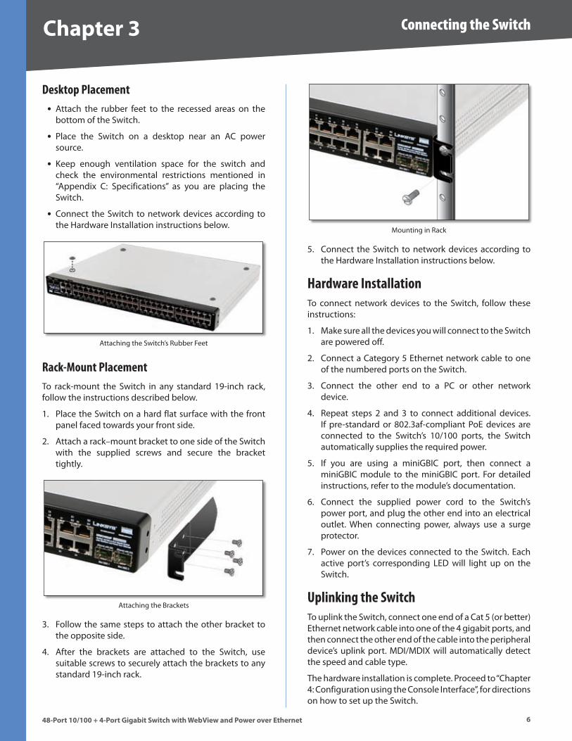
Desktop PlacementAttach the rubber feet to the recessed areas on the bottom of the Switch .
Place the Switch on a desktop near an AC power source .
Keep enough ventilation space for the switch and check the environmental restrictions mentioned in “Appendix C: Specifications” as you are placing the Switch .
Connect the Switch to network devices according to the Hardware Installation instructions below .
Attaching the Switch’s Rubber Feet
Rack-Mount PlacementTo rack-mount the Switch in any standard 19-inch rack, follow the instructions described below .
Place the Switch on a hard flat surface with the front panel faced towards your front side .
Attach a rack–mount bracket to one side of the Switch with the supplied screws and secure the bracket tightly .
Attaching the Brackets
Follow the same steps to attach the other bracket to the opposite side .
After the brackets are attached to the Switch, use suitable screws to securely attach the brackets to any standard 19-inch rack .
•
•
•
•
1 .
2 .
3 .
4 .
Mounting in Rack
Connect the Switch to network devices according to the Hardware Installation instructions below .
Hardware InstallationTo connect network devices to the Switch, follow these instructions:
Make sure all the devices you will connect to the Switch are powered off .
Connect a Category 5 Ethernet network cable to one of the numbered ports on the Switch .
Connect the other end to a PC or other network device .
Repeat steps 2 and 3 to connect additional devices . If pre-standard or 802 .3af-compliant PoE devices are connected to the Switch’s 10/100 ports, the Switch automatically supplies the required power .
If you are using a miniGBIC port, then connect a miniGBIC module to the miniGBIC port . For detailed instructions, refer to the module’s documentation .
Connect the supplied power cord to the Switch’s power port, and plug the other end into an electrical outlet . When connecting power, always use a surge protector .
Power on the devices connected to the Switch . Each active port’s corresponding LED will light up on the Switch .
Uplinking the SwitchTo uplink the Switch, connect one end of a Cat 5 (or better) Ethernet network cable into one of the 4 gigabit ports, and then connect the other end of the cable into the peripheral device’s uplink port . MDI/MDIX will automatically detect the speed and cable type .
The hardware installation is complete . Proceed to “Chapter 4: Configuration using the Console Interface”, for directions on how to set up the Switch .
5 .
1 .
2 .
3 .
4 .
5 .
6 .
7 .
�
Configuration Using the Console Interface
48-Port 10/100 + 4-Port G�gab�t Sw�tch w�th WebV�ew and Power over Ethernet
Chapter 4
Chapter 4: Conf�gurat�on Us�ng the Console Interface
OverviewThe Switch features a menu-driven console interface for basic switch configuration . You can easily manage your network from the screens through the console port . Before you can use the console interface, you will need to configure the HyperTerminal application .
Configuring the HyperTerminal ApplicationClick the Start button .
Select Programs > Accessor�es > Commun�cat�ons > HyperTerm�nal .
Start > Programs > Accessories > Communications > HyperTerminal
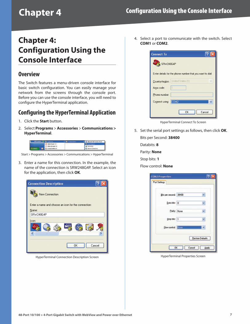
Enter a name for this connection . In the example, the name of the connection is SRW248G4P . Select an icon for the application, then click OK .
HyperTerminal Connection Description Screen
1 .
2 .
3 .
Select a port to communicate with the switch . Select COM1 or COM� .
HyperTerminal Connect To Screen
Set the serial port settings as follows, then click OK .
Bits per Second: �8400
Databits: 8
Parity: None
Stop bits: 1
Flow control: None
HyperTerminal Properties Screen
4 .
5 .
8
Configuration Using the Console Interface
48-Port 10/100 + 4-Port G�gab�t Sw�tch w�th WebV�ew and Power over Ethernet
Chapter 4
Configuring the Switch through the Console InterfaceThe Console Interface consist of a series of menus . Each menu has several options, which are listed vertically . A highlight in each menu lets you select the option you wish to choose; pressing the Enter key activates the highlighted option .
To navigate through the Console Interface, use the Up Arrow or Down Arrow keys or use the Number keys to select the respective option (for example, press the � key to highlight Help) . The Enter key selects an option and the Esc key returns to the previous selection; menu options and any values entered or present are highlighted . Note that the bottom of the window provides help, indicating the appropriate keys to use .
LoginWhen you finish configuring the HyperTerminal, the Login screen appears . The first time you open the Console Interface, use the default username admin and leave the password blank and press the Enter key . You can set a password later from the User and Password Settings screen .
Console Login Screen
Switch Main MenuThe Main Menu screen displays six menu choices: System Configuration Menu, Port Status, Port Configuration, PoE Configuration, Help, and Log Out .
Main Menu
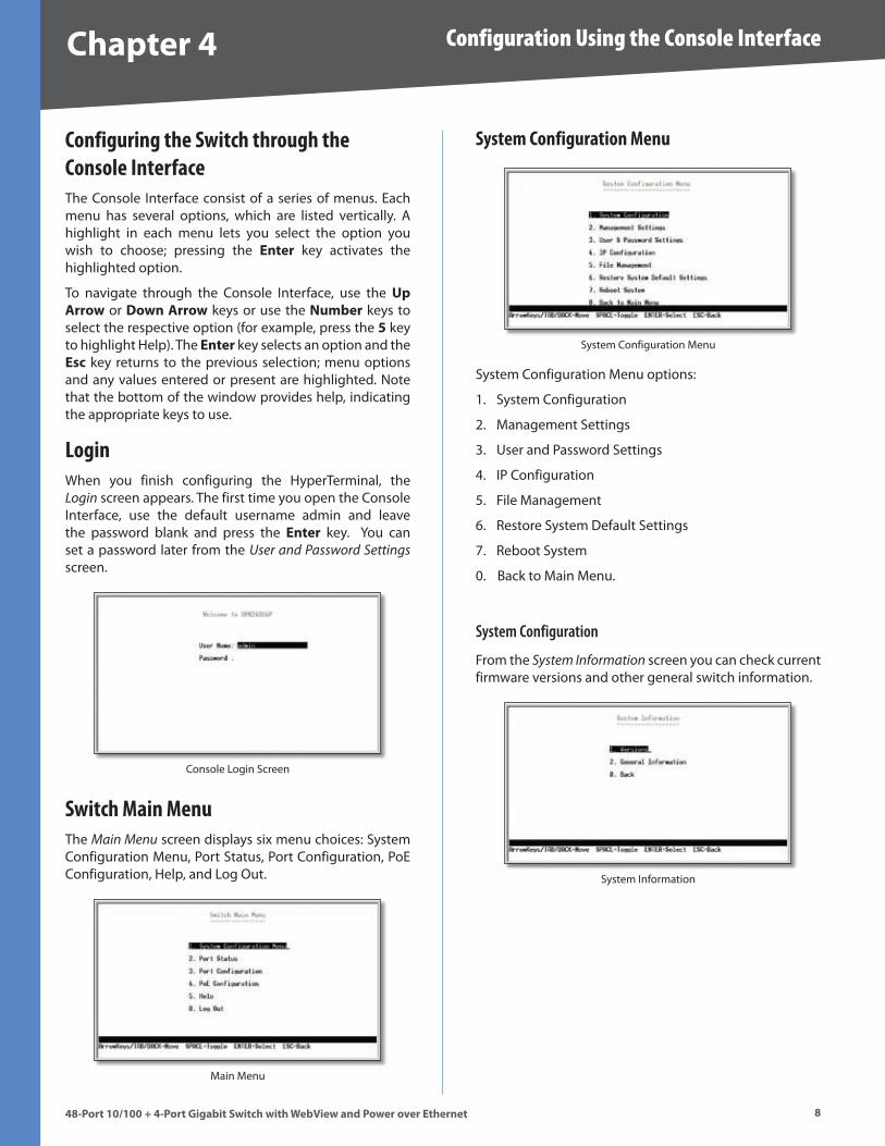
System Configuration Menu
System Configuration Menu
System Configuration Menu options:
System Configuration
Management Settings
User and Password Settings
IP Configuration
File Management
Restore System Default Settings
Reboot System
0 . Back to Main Menu .
System Configuration
From the System Information screen you can check current firmware versions and other general switch information .
System Information
1 .
2 .
3 .
4 .
5 .
6 .
7 .
�
Configuration Using the Console Interface
48-Port 10/100 + 4-Port G�gab�t Sw�tch w�th WebV�ew and Power over Ethernet
Chapter 4
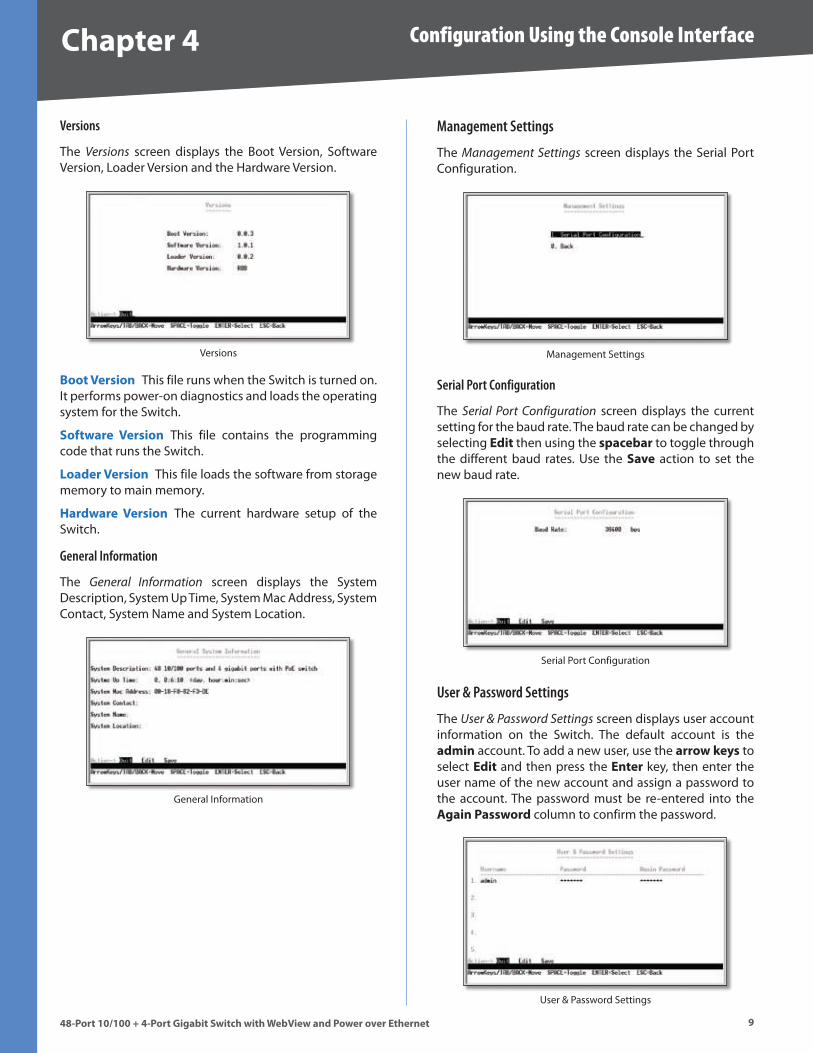
Versions
The Versions screen displays the Boot Version, Software Version, Loader Version and the Hardware Version .
Versions
Boot Vers�on This file runs when the Switch is turned on . It performs power-on diagnostics and loads the operating system for the Switch .
Software Vers�on This file contains the programming code that runs the Switch .
Loader Vers�on This file loads the software from storage memory to main memory .
Hardware Vers�on The current hardware setup of the Switch .
General Information
The General Information screen displays the System Description, System Up Time, System Mac Address, System Contact, System Name and System Location .
General Information
Management Settings
The Management Settings screen displays the Serial Port Configuration .
Management Settings
Serial Port Configuration
The Serial Port Configuration screen displays the current setting for the baud rate . The baud rate can be changed by selecting Ed�t then using the spacebar to toggle through the different baud rates . Use the Save action to set the new baud rate .
Serial Port Configuration
User & Password Settings
The User & Password Settings screen displays user account information on the Switch . The default account is the adm�n account . To add a new user, use the arrow keys to select Ed�t and then press the Enter key, then enter the user name of the new account and assign a password to the account . The password must be re-entered into the Aga�n Password column to confirm the password .
User & Password Settings
10
Configuration Using the Console Interface
48-Port 10/100 + 4-Port G�gab�t Sw�tch w�th WebV�ew and Power over Ethernet
Chapter 4
You can add up to five user accounts in addition to the default admin account . The admin account cannot be deleted from the system .
To save the new user account information, use the arrow keys to select Save and press Enter .
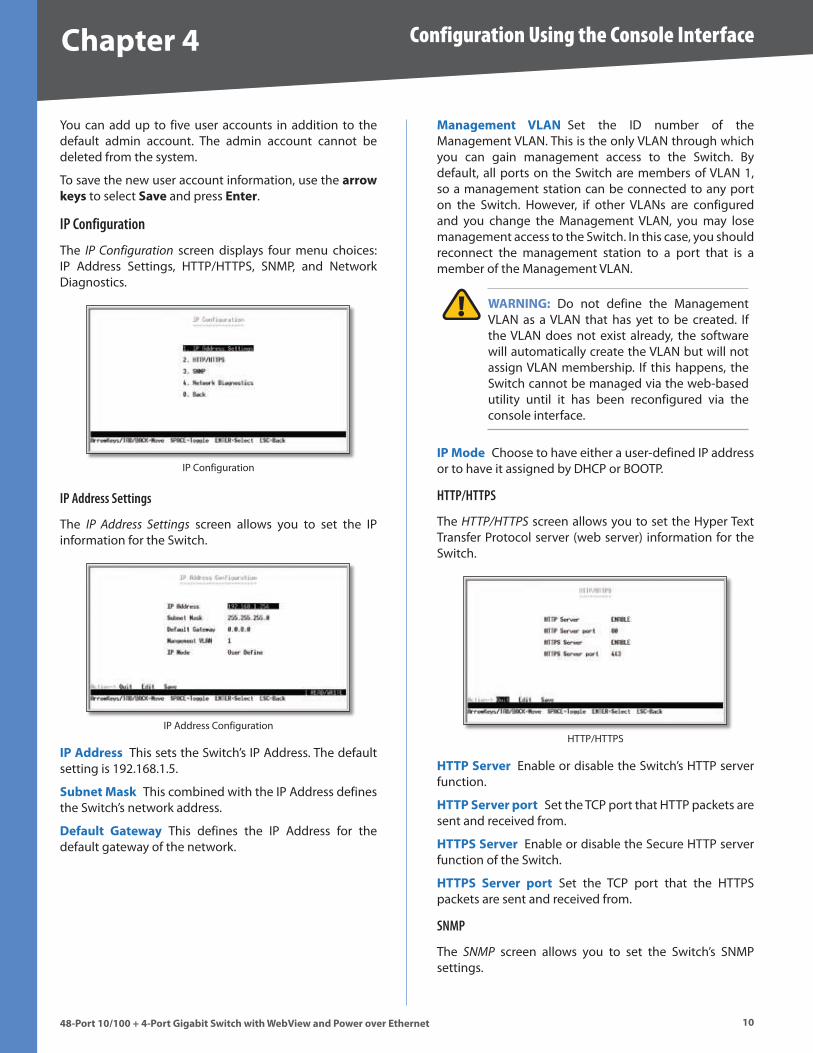
IP Configuration
The IP Configuration screen displays four menu choices: IP Address Settings, HTTP/HTTPS, SNMP, and Network Diagnostics .
IP Configuration
IP Address Settings
The IP Address Settings screen allows you to set the IP information for the Switch .
IP Address Configuration
IP Address This sets the Switch’s IP Address . The default setting is 192 .168 .1 .5 .
Subnet Mask This combined with the IP Address defines the Switch’s network address .
Default Gateway This defines the IP Address for the default gateway of the network .
Management VLAN Set the ID number of the Management VLAN . This is the only VLAN through which you can gain management access to the Switch . By default, all ports on the Switch are members of VLAN 1, so a management station can be connected to any port on the Switch . However, if other VLANs are configured and you change the Management VLAN, you may lose management access to the Switch . In this case, you should reconnect the management station to a port that is a member of the Management VLAN .
WARNING: Do not define the Management VLAN as a VLAN that has yet to be created . If the VLAN does not exist already, the software will automatically create the VLAN but will not assign VLAN membership . If this happens, the Switch cannot be managed via the web-based utility until it has been reconfigured via the console interface .
IP Mode Choose to have either a user-defined IP address or to have it assigned by DHCP or BOOTP .
HTTP/HTTPS
The HTTP/HTTPS screen allows you to set the Hyper Text Transfer Protocol server (web server) information for the Switch .
HTTP/HTTPS
HTTP Server Enable or disable the Switch’s HTTP server function .
HTTP Server port Set the TCP port that HTTP packets are sent and received from .
HTTPS Server Enable or disable the Secure HTTP server function of the Switch .
HTTPS Server port Set the TCP port that the HTTPS packets are sent and received from .
SNMP
The SNMP screen allows you to set the Switch’s SNMP settings .
11
Configuration Using the Console Interface
48-Port 10/100 + 4-Port G�gab�t Sw�tch w�th WebV�ew and Power over Ethernet
Chapter 4
SNMP
SNMP Server Enable or Disable the SNMP function for the Switch .
SNMP Server Port Set the TCP port that will be used for sending and receiving SNMP packets .
Network Diagnostics
The Network Configuration screen allows you to use PING to test network connectivity . Enter the IP address of the interface or device you wish to PING and select the Execute action .
Ping
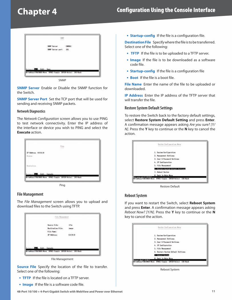
File Management
The File Management screen allows you to upload and download files to the Switch using TFTP .
File Management
Source F�le Specify the location of the file to transfer . Select one of the following:
TFTP If the file is located on a TFTP server .
Image If the file is a software code file .
•
•
Startup-conf�g If the file is a configuration file .
Dest�nat�on F�le Specify where the file is to be transferred . Select one of the following:
TFTP If the file is to be uploaded to a TFTP server .
Image If the file is to be downloaded as a software code file .
Startup-conf�g If the file is a configuration file
Boot If the file is a boot file .
F�le Name Enter the name of the file to be uploaded or downloaded .
IP Address Enter the IP address of the TFTP server that will transfer the file .
Restore System Default Settings
To restore the Switch back to the factory default settings, select Restore System Default Sett�ng and press Enter . A confirmation message appears asking Are you sure? [Y/N] . Press the Y key to continue or the N key to cancel the action .
Restore Default
Reboot System
If you want to restart the Switch, select Reboot System and press Enter . A confirmation message appears asking Reboot Now? [Y/N] . Press the Y key to continue or the N key to cancel the action .
Reboot System
•
•
•
•
•
1�
Configuration Using the Console Interface
48-Port 10/100 + 4-Port G�gab�t Sw�tch w�th WebV�ew and Power over Ethernet
Chapter 4
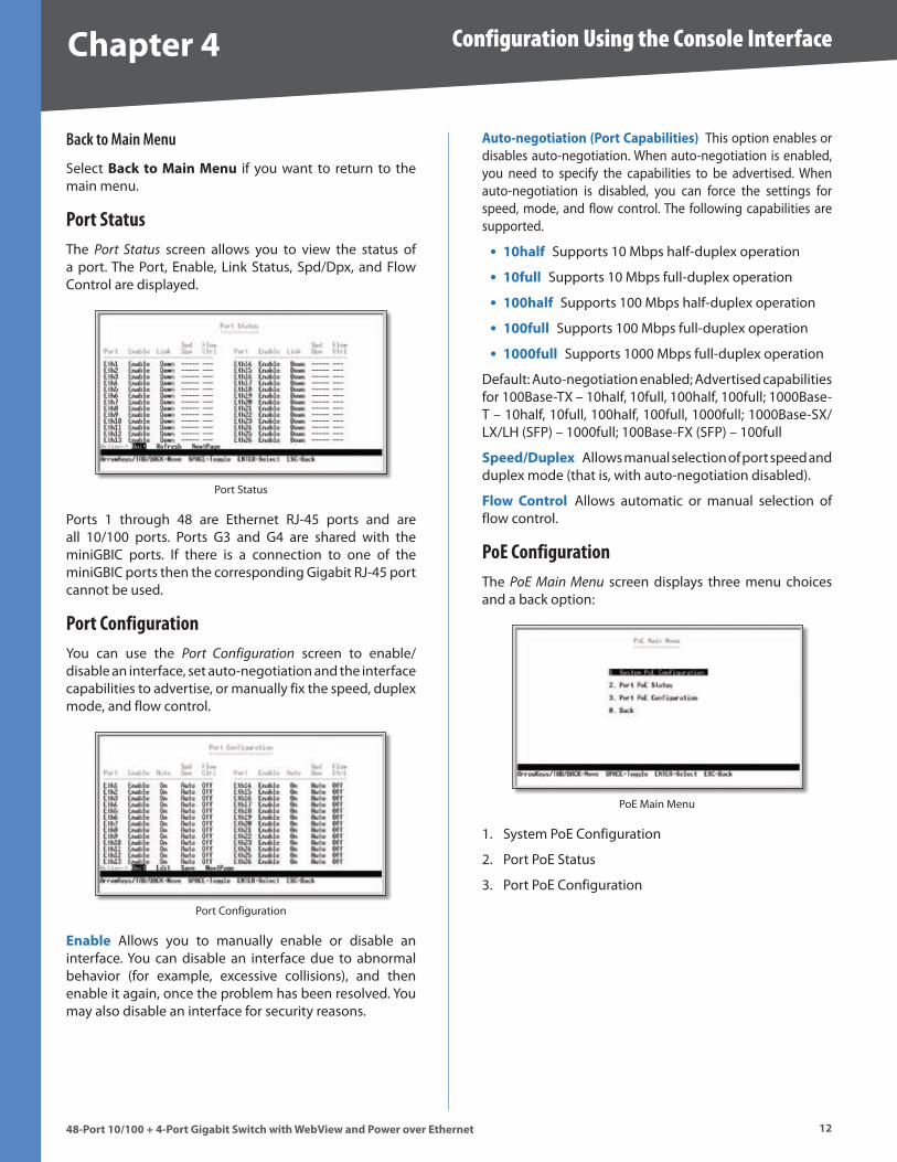
Back to Main Menu
Select Back to Ma�n Menu if you want to return to the main menu .
Port StatusThe Port Status screen allows you to view the status of a port . The Port, Enable, Link Status, Spd/Dpx, and Flow Control are displayed .
Port Status
Ports 1 through 48 are Ethernet RJ-45 ports and are all 10/100 ports . Ports G3 and G4 are shared with the miniGBIC ports . If there is a connection to one of the miniGBIC ports then the corresponding Gigabit RJ-45 port cannot be used .
Port ConfigurationYou can use the Port Configuration screen to enable/disable an interface, set auto-negotiation and the interface capabilities to advertise, or manually fix the speed, duplex mode, and flow control .
Port Configuration
Enable Allows you to manually enable or disable an interface . You can disable an interface due to abnormal behavior (for example, excessive collisions), and then enable it again, once the problem has been resolved . You may also disable an interface for security reasons .
Auto-negot�at�on (Port Capab�l�t�es) This option enables or disables auto-negotiation . When auto-negotiation is enabled, you need to specify the capabilities to be advertised . When auto-negotiation is disabled, you can force the settings for speed, mode, and flow control . The following capabilities are supported .
10half Supports 10 Mbps half-duplex operation
10full Supports 10 Mbps full-duplex operation
100half Supports 100 Mbps half-duplex operation
100full Supports 100 Mbps full-duplex operation
1000full Supports 1000 Mbps full-duplex operation
Default: Auto-negotiation enabled; Advertised capabilities for 100Base-TX – 10half, 10full, 100half, 100full; 1000Base-T – 10half, 10full, 100half, 100full, 1000full; 1000Base-SX/LX/LH (SFP) – 1000full; 100Base-FX (SFP) – 100full
Speed/Duplex Allows manual selection of port speed and duplex mode (that is, with auto-negotiation disabled) .
Flow Control Allows automatic or manual selection of flow control .
PoE ConfigurationThe PoE Main Menu screen displays three menu choices and a back option:
PoE Main Menu
System PoE Configuration
Port PoE Status
Port PoE Configuration
•
•
•
•
•
1 .
2 .
3 .
1�
Configuration Using the Console Interface
48-Port 10/100 + 4-Port G�gab�t Sw�tch w�th WebV�ew and Power over Ethernet
Chapter 4
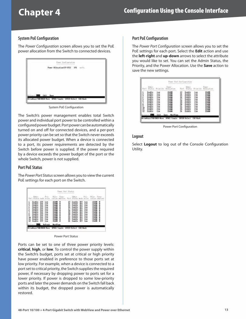
System PoE Configuration
The Power Configuration screen allows you to set the PoE power allocation from the Switch to connected devices .
System PoE Configuration
The Switch’s power management enables total Switch power and individual port power to be controlled within a configured power budget . Port power can be automatically turned on and off for connected devices, and a per-port power priority can be set so that the Switch never exceeds its allocated power budget . When a device is connected to a port, its power requirements are detected by the Switch before power is supplied . If the power required by a device exceeds the power budget of the port or the whole Switch, power is not supplied .
Port PoE Status
The Power Port Status screen allows you to view the current PoE settings for each port on the Switch .
Power Port Status
Ports can be set to one of three power priority levels: cr�t�cal, h�gh, or low . To control the power supply within the Switch’s budget, ports set at critical or high priority have power enabled in preference to those ports set at low priority . For example, when a device is connected to a port set to critical priority, the Switch supplies the required power, if necessary by dropping power to ports set for a lower priority . If power is dropped to some low-priority ports and later the power demands on the Switch fall back within its budget, the dropped power is automatically restored .
Port PoE Configuration
The Power Port Configuration screen allows you to set the PoE settings for each port . Select the Ed�t action and use the left-r�ght and up-down arrows to select the attribute you would like to set . You can set the Admin Status, the Priority, and the Power Allocation . Use the Save action to save the new settings .
Power Port Configuration
Logout
Select Logout to log out of the Console Configuration Utility .
Chapter � Configuring the Switch
1448-Port 10/100 + 4-Port G�gab�t Sw�tch w�th WebV�ew and Power over Ethernet
Chapter �: Conf�gur�ng the Sw�tchOpen your web browser and enter http://1��.1�8.1.��4 into the address field . Press the Enter key and the Password screen will appear .
Address Bar
NOTE: The default IP address is 1��.1�8.1.��4 . If the IP address has been changed using DHCP or via the console interface, enter the assigned IP address instead of the default .
The first time you open the web-based utility, enter adm�n (the default username) in the username field and leave the password blank . Click the OK button . You can set a password later from the Admin tab’s User Accounts screen .
Login Screen
SetupThe first screen displays the Summary screen on the Setup tab . There are 10 tabs across the top of the screen: Setup, Port management, VLAN Management, Stat�st�cs, ACL, Secur�ty, QoS, Spann�ng Tree, Mult�cast, and a More tab . Click the More tab to access the SNMP, Adm�n and Logout tabs . Each tab contains screens that will help you configure and manage the Switch .
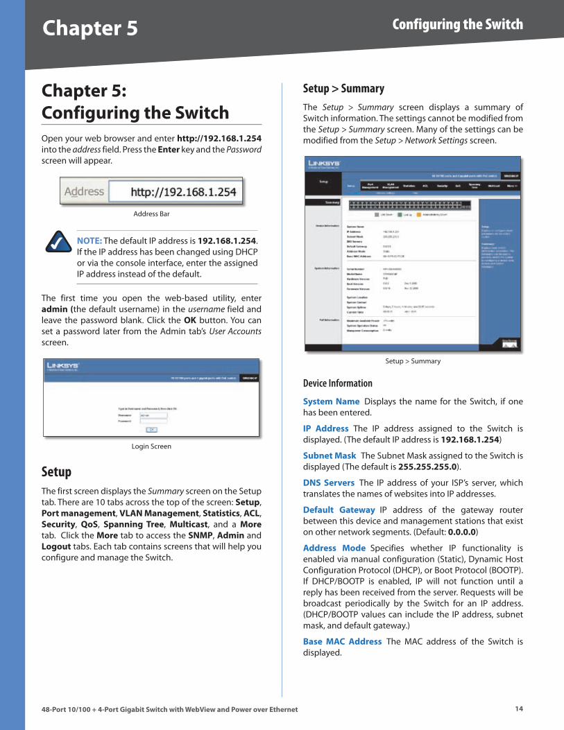
Setup > SummaryThe Setup > Summary screen displays a summary of Switch information . The settings cannot be modified from the Setup > Summary screen . Many of the settings can be modified from the Setup > Network Settings screen .
Setup > Summary
Device Information
System Name Displays the name for the Switch, if one has been entered .
IP Address The IP address assigned to the Switch is displayed . (The default IP address is 1��.1�8.1.��4)
Subnet Mask The Subnet Mask assigned to the Switch is displayed (The default is ���.���.���.0) .
DNS Servers The IP address of your ISP’s server, which translates the names of websites into IP addresses .
Default Gateway IP address of the gateway router between this device and management stations that exist on other network segments . (Default: 0.0.0.0)
Address Mode Specifies whether IP functionality is enabled via manual configuration (Static), Dynamic Host Configuration Protocol (DHCP), or Boot Protocol (BOOTP) . If DHCP/BOOTP is enabled, IP will not function until a reply has been received from the server . Requests will be broadcast periodically by the Switch for an IP address . (DHCP/BOOTP values can include the IP address, subnet mask, and default gateway .)
Base MAC Address The MAC address of the Switch is displayed .
Chapter � Configuring the Switch
1�48-Port 10/100 + 4-Port G�gab�t Sw�tch w�th WebV�ew and Power over Ethernet
System Information
Ser�al Number The serial number of the Switch is displayed .
Model Name The model name of the Switch is displayed .
Hardware vers�on The current hardware version is displayed .
Boot Vers�on The current boot version is displayed .
F�rmware Vers�on The current software version is displayed .
System Locat�on Displays the location of the system if it has been defined .
System Contact The name of the administrator will appear here if it has been defined .
System Upt�me Length of time the management agent has been up .
Current T�me Displays the current time .
PoE Information
Max�mum Ava�lable Power Displays the maximum power that can be supplied to a connected PoE device .
System Operat�on Status Displays the operational status of the Power over Ethernet mechanism .
Ma�npower Consumpt�on Displays the current number of watts that the Switch is providing to PoE devices .
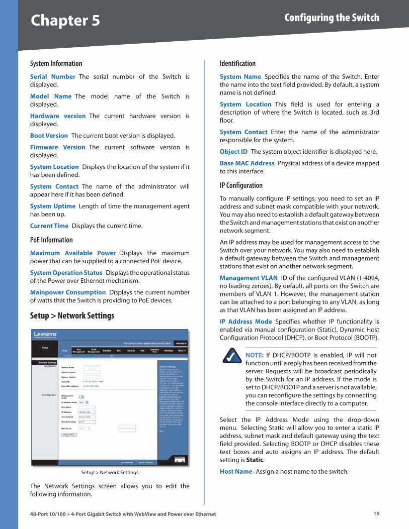
Setup > Network Settings
Setup > Network Settings
The Network Settings screen allows you to edit the following information .
Identification
System Name Specifies the name of the Switch . Enter the name into the text field provided . By default, a system name is not defined .
System Locat�on This field is used for entering a description of where the Switch is located, such as 3rd floor .
System Contact Enter the name of the administrator responsible for the system .
Object ID The system object identifier is displayed here .
Base MAC Address Physical address of a device mapped to this interface .
IP Configuration
To manually configure IP settings, you need to set an IP address and subnet mask compatible with your network . You may also need to establish a default gateway between the Switch and management stations that exist on another network segment .
An IP address may be used for management access to the Switch over your network . You may also need to establish a default gateway between the Switch and management stations that exist on another network segment .
Management VLAN ID of the configured VLAN (1-4094, no leading zeroes) . By default, all ports on the Switch are members of VLAN 1 . However, the management station can be attached to a port belonging to any VLAN, as long as that VLAN has been assigned an IP address .
IP Address Mode Specifies whether IP functionality is enabled via manual configuration (Static), Dynamic Host Configuration Protocol (DHCP), or Boot Protocol (BOOTP) .
NOTE: If DHCP/BOOTP is enabled, IP will not function until a reply has been received from the server . Requests will be broadcast periodically by the Switch for an IP address . If the mode is set to DHCP/BOOTP and a server is not available, you can reconfigure the settings by connecting the console interface directly to a computer .
Select the IP Address Mode using the drop-down menu . Selecting Static will allow you to enter a static IP address, subnet mask and default gateway using the text field provided . Selecting BOOTP or DHCP disables these text boxes and auto assigns an IP address . The default setting is Stat�c .
Host Name Assign a host name to the switch .
Chapter � Configuring the Switch
1�48-Port 10/100 + 4-Port G�gab�t Sw�tch w�th WebV�ew and Power over Ethernet
IP Address Address of the VLAN interface that is allowed management access . Valid IP addresses consist of four numbers, 0 to 255, separated by periods . (Default: 1��.1�8.1.��4)
Subnet Mask This mask identifies the host address bits used for routing to specific subnets . (Default: ���.���.���.0)
Default Gateway IP address of the gateway router between this device and management stations that exist on other network segments . (Default: 0.0.0.0)
DNS Server Enter the IP address of the DNS server into the text field . A second DNS address can be specified in the additional text field provided .
Click Save Sett�ngs to save the changes .
Click Restart DHCP to assign a new IP address using DHCP .
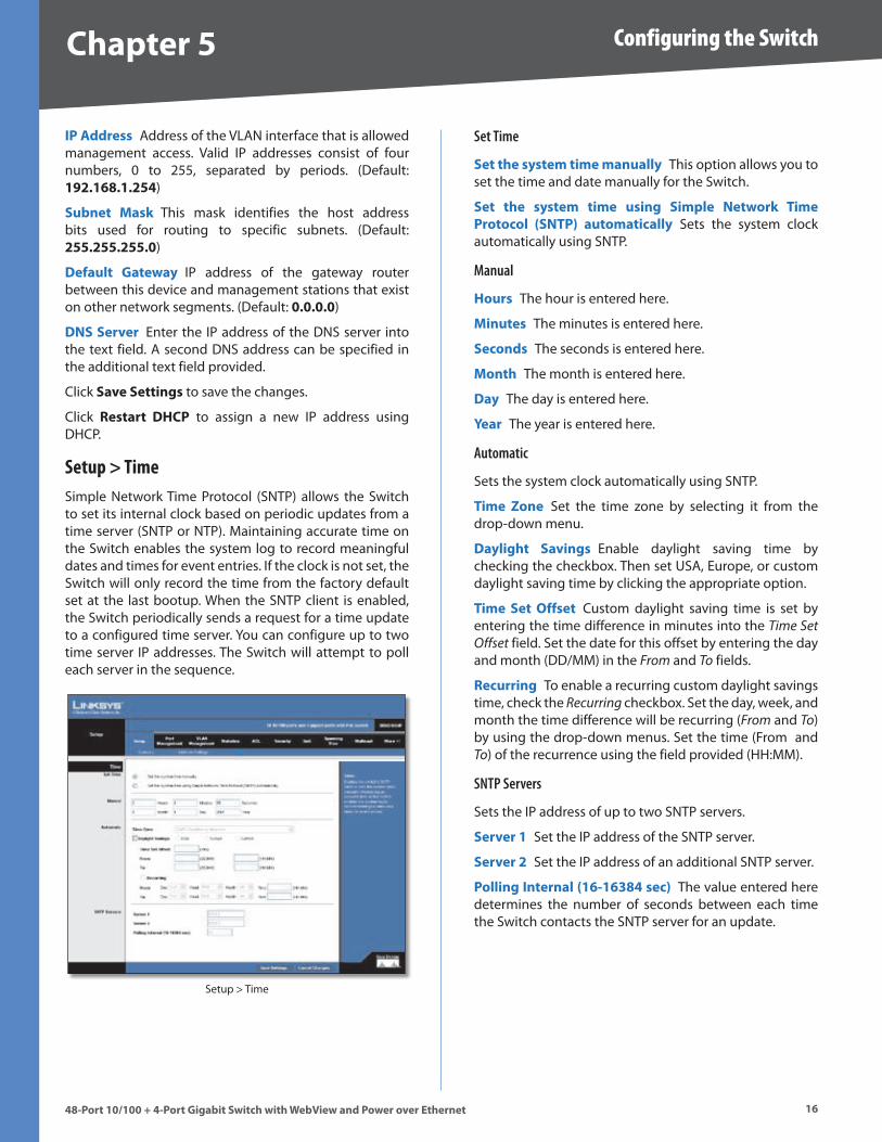
Setup > TimeSimple Network Time Protocol (SNTP) allows the Switch to set its internal clock based on periodic updates from a time server (SNTP or NTP) . Maintaining accurate time on the Switch enables the system log to record meaningful dates and times for event entries . If the clock is not set, the Switch will only record the time from the factory default set at the last bootup . When the SNTP client is enabled, the Switch periodically sends a request for a time update to a configured time server . You can configure up to two time server IP addresses . The Switch will attempt to poll each server in the sequence .
Setup > Time
Set Time
Set the system t�me manually This option allows you to set the time and date manually for the Switch .
Set the system t�me us�ng S�mple Network T�me Protocol (SNTP) automat�cally Sets the system clock automatically using SNTP .
Manual
Hours The hour is entered here .
M�nutes The minutes is entered here .
Seconds The seconds is entered here .
Month The month is entered here .
Day The day is entered here .
Year The year is entered here .
Automatic
Sets the system clock automatically using SNTP .
T�me Zone Set the time zone by selecting it from the drop-down menu .
Dayl�ght Sav�ngs Enable daylight saving time by checking the checkbox . Then set USA, Europe, or custom daylight saving time by clicking the appropriate option .
T�me Set Offset Custom daylight saving time is set by entering the time difference in minutes into the Time Set Offset field . Set the date for this offset by entering the day and month (DD/MM) in the From and To fields .
Recurr�ng To enable a recurring custom daylight savings time, check the Recurring checkbox . Set the day, week, and month the time difference will be recurring (From and To) by using the drop-down menus . Set the time (From and To) of the recurrence using the field provided (HH:MM) .
SNTP Servers
Sets the IP address of up to two SNTP servers .
Server 1 Set the IP address of the SNTP server .
Server � Set the IP address of an additional SNTP server .
Poll�ng Internal (1�-1��84 sec) The value entered here determines the number of seconds between each time the Switch contacts the SNTP server for an update .
Chapter � Configuring the Switch
1�48-Port 10/100 + 4-Port G�gab�t Sw�tch w�th WebV�ew and Power over Ethernet
Port ManagementPort functionality can be controlled using the Port Management settings . Speeds, duplex, grouping, and Power over Ethernet settings, and more can be defined .
Port Management > Port SettingsYou can manually configure the speed, duplex mode, and flow control used on specific ports, or use to detect the connection settings used by the attached device . Use the full-duplex mode on ports whenever possible to double the throughput of switch connections . Flow control should also be enabled to control network traffic during periods of congestion and prevent the loss of packets when port buffer thresholds are exceeded . The Switch supports flow control based on the IEEE 802 .3x standard .
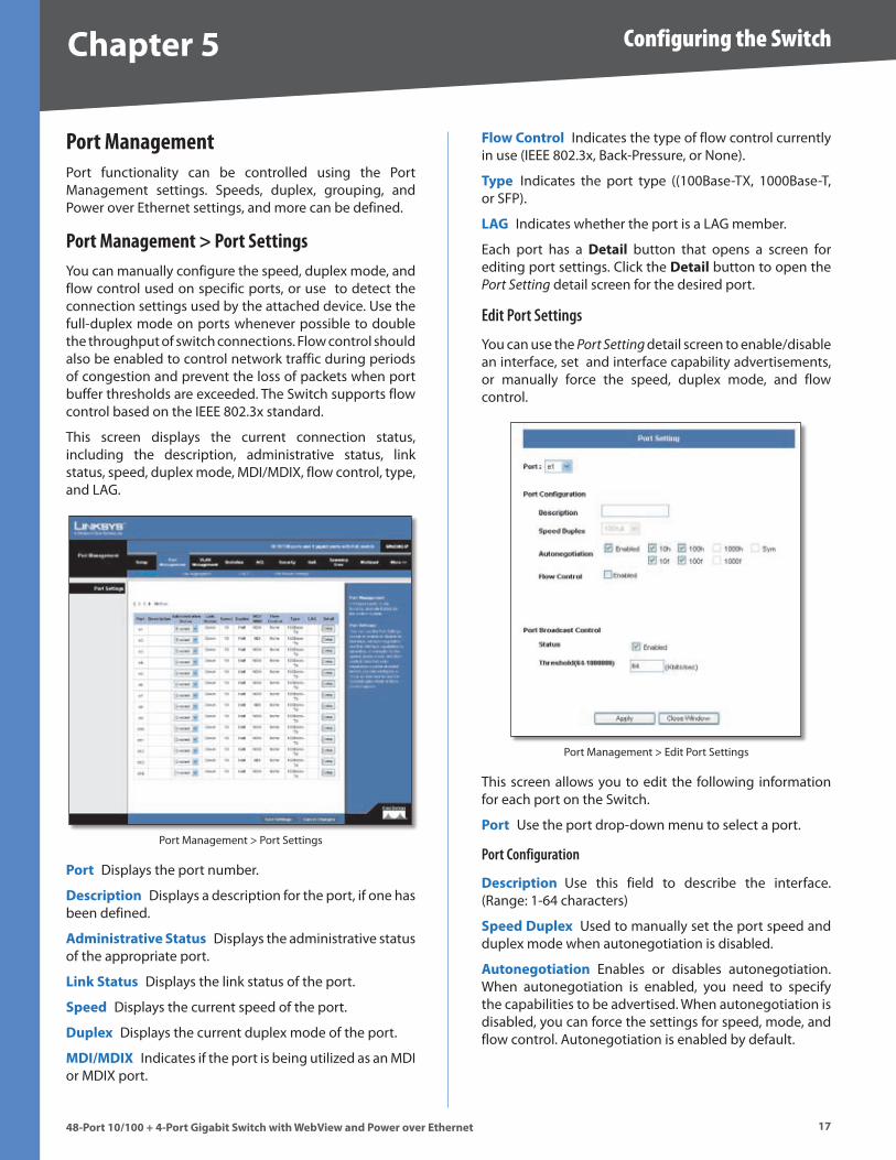
This screen displays the current connection status, including the description, administrative status, link status, speed, duplex mode, MDI/MDIX, flow control, type, and LAG .
Port Management > Port Settings
Port Displays the port number .
Descr�pt�on Displays a description for the port, if one has been defined .
Adm�n�strat�ve Status Displays the administrative status of the appropriate port .
L�nk Status Displays the link status of the port .
Speed Displays the current speed of the port .
Duplex Displays the current duplex mode of the port .
MDI/MDIX Indicates if the port is being utilized as an MDI or MDIX port .
Flow Control Indicates the type of flow control currently in use (IEEE 802 .3x, Back-Pressure, or None) .
Type Indicates the port type ((100Base-TX, 1000Base-T, or SFP) .
LAG Indicates whether the port is a LAG member .
Each port has a Deta�l button that opens a screen for editing port settings . Click the Deta�l button to open the Port Setting detail screen for the desired port .
Edit Port Settings
You can use the Port Setting detail screen to enable/disable an interface, set and interface capability advertisements, or manually force the speed, duplex mode, and flow control .
Port Management > Edit Port Settings
This screen allows you to edit the following information for each port on the Switch .
Port Use the port drop-down menu to select a port .
Port Configuration
Descr�pt�on Use this field to describe the interface . (Range: 1-64 characters)
Speed Duplex Used to manually set the port speed and duplex mode when autonegotiation is disabled .
Autonegot�at�on Enables or disables autonegotiation . When autonegotiation is enabled, you need to specify the capabilities to be advertised . When autonegotiation is disabled, you can force the settings for speed, mode, and flow control . Autonegotiation is enabled by default .

Chapter � Configuring the Switch
1848-Port 10/100 + 4-Port G�gab�t Sw�tch w�th WebV�ew and Power over Ethernet
The following capabilities are supported .
10half Supports 10 Mbps half-duplex operation
10full Supports 10 Mbps full-duplex operation
100half Supports 100 Mbps half-duplex operation
100full Supports 100 Mbps full-duplex operation
1000half Supports 1000 Mbps half-duplex operation
1000full Supports 1000 Mbps full-duplex operation
Sym (Gigabit only) Check this item to transmit and receive pause frames, or clear it to autonegotiate the sender and receiver for asymmetric pause frames .
Flow Control Allows automatic or manual selection of flow control .
Port Broadcast Control
Status To enable broadcast control on a specified port, mark the Enabled checkbox for that port .
Threshold You can protect your network from broadcast storms by setting a threshold for broadcast traffic for all ports . Any broadcast packets exceeding the specified threshold will then be dropped .
After you modify the required port settings, click Apply .
Port Management > Link AggregationYou can create multiple links between devices that work as one virtual, aggregate link (LAG) . An aggregated link offers a dramatic increase in bandwidth for network segments where bottlenecks exist, as well as providing a fault-tolerant link between two devices . You can create up to four LAGs on the Switch . Each LAG can contain up to eight ports .
Port Management > Link Aggregation
•
•
•
•
•
•
•
LAG Displays the LAG number .
Descr�pt�on Displays the description assigned to the interface .
Adm�n�strat�ve Status Indicates whether the interface is enabled or disabled .
Type Indicates if a LAG has been manually configured (static) or dynamically set through LACP .
L�nk Status Displays the status of the link .
Speed Displays the port speed .
Duplex Displays the duplex mode .
Flow Control Displays the flow control .
Create To create a new LAG, click the Create button in the Create column, then add members to the LAG by clicking on the Select Member button . The select member screen for the Link Aggregation opens .
Port Management > Link Aggregation > Select Member
The LAG number is shown in the LAG drop-down menu . The Ethernet ports are represented by check boxes . Assign up to 8 ports to the LAG by checking the checkboxes of the ports, then click Apply .
Deta�l To configure the LAG and the LAG broadcast control, click the Deta�l button . The Link Aggregation detail screen will be displayed .
Port Management > Link Aggregation > Detail
Chapter � Configuring the Switch
1�48-Port 10/100 + 4-Port G�gab�t Sw�tch w�th WebV�ew and Power over Ethernet
Descr�pt�on Allows you to describe an interface .
Flow Control Click the checkbox to enable flow control .
Autonegot�at�on Click the checkbox to enable autonegotiation .
LAG Broadcast Control You can protect your network from broadcast storms by setting a threshold for broadcast traffic for all LAGs . Any broadcast packets exceeding the specified threshold will then be dropped .
Status Click the checkbox to enable LAG Broadcast Control .
Threshold Set the threshold for the LAG, click apply .
Delete To delete a LAG, click the Delete button .
Port Management > LACPPorts can be statically grouped into an aggregate link (that is, LAG) to increase the bandwidth of a network connection or to ensure fault recovery . Or you can use the Link Aggregation Control Protocol (LACP) to automatically negotiate a LAG link between the Switch and another network device . For static LAGs, the switches have to comply with the Cisco EtherChannel standard . For dynamic LAGs, the switches have to comply with LACP . This Switch supports up to four LAGs . For example, a LAG consisting of two 1000 Mbps ports can support an aggregate bandwidth of 4 Gbps when operating at full duplex .
To avoid creating a loop in the network, be sure you enable LACP before connecting the ports, and also disconnect the ports before disabling LACP .
Port Management > LACP
Set Port Actor This menu sets the local side of an aggregate link; that is, the ports on this Switch .
Set the System Pr�or�ty, Port Pr�or�ty and LACP T�meout for the Port Actor After you have completed setting the port LACP parameters, click Save Sett�ngs .
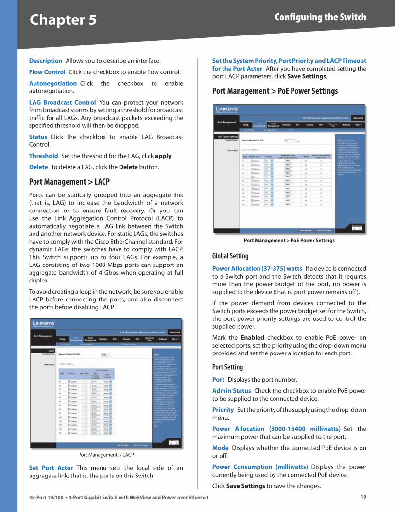
Port Management > PoE Power Settings
Port Management > PoE Power Sett�ngs
Global Setting
Power Allocat�on (��-���) watts If a device is connected to a Switch port and the Switch detects that it requires more than the power budget of the port, no power is supplied to the device (that is, port power remains off ) .
If the power demand from devices connected to the Switch ports exceeds the power budget set for the Switch, the port power priority settings are used to control the supplied power .
Mark the Enabled checkbox to enable PoE power on selected ports, set the priority using the drop-down menu provided and set the power allocation for each port .
Port Setting
Port Displays the port number .
Adm�n Status Check the checkbox to enable PoE power to be supplied to the connected device .
Pr�or�ty Set the priority of the supply using the drop-down menu .
Power Allocat�on (�000-1�400 m�ll�watts) Set the maximum power that can be supplied to the port .
Mode Displays whether the connected PoE device is on or off .
Power Consumpt�on (m�ll�watts) Displays the power currently being used by the connected PoE device .
Click Save Sett�ngs to save the changes .
Chapter � Configuring the Switch
�048-Port 10/100 + 4-Port G�gab�t Sw�tch w�th WebV�ew and Power over Ethernet
VLAN ManagementA VLAN is a group of ports that can be located anywhere in the network, but communicate as though they belong to the same physical segment .
VLANs help to simplify network management by allowing you to move devices to a new VLAN without having to change any physical connections . VLANs can be easily organized to reflect departmental groups (such as Marketing or R&D), usage groups (such as e-mail), or multicast groups (used for multimedia applications such as videoconferencing) . You can create up to 256 VLANs on the Switch .
VLAN Management > Create VLAN
VLAN Management > Create VLAN
Create VLAN
Single VLAN
To create a single VLAN, enter the VLAN ID and VLAN Name, up to 32 characters long, and click Add .
VLAN ID ID of configured VLAN (1-4094, no leading zeroes) .
VLAN Name Name of the VLAN . (1 to 32 characters)
VLAN Range
To create a range of VLANs, enter the range of the VLAN IDs to be created in to the VLAN Range fields and then click Add Range .
To remove a VLAN or a range of VLANs, select the VLANs in the VLAN list, then click Remove .
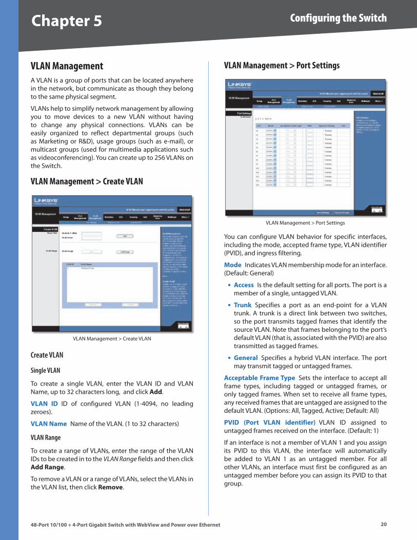
VLAN Management > Port Settings
VLAN Management > Port Settings
You can configure VLAN behavior for specific interfaces, including the mode, accepted frame type, VLAN identifier (PVID), and ingress filtering .
Mode Indicates VLAN membership mode for an interface . (Default: General)
Access Is the default setting for all ports . The port is a member of a single, untagged VLAN .
Trunk Specifies a port as an end-point for a VLAN trunk . A trunk is a direct link between two switches, so the port transmits tagged frames that identify the source VLAN . Note that frames belonging to the port’s default VLAN (that is, associated with the PVID) are also transmitted as tagged frames .
General Specifies a hybrid VLAN interface . The port may transmit tagged or untagged frames .
Acceptable Frame Type Sets the interface to accept all frame types, including tagged or untagged frames, or only tagged frames . When set to receive all frame types, any received frames that are untagged are assigned to the default VLAN . (Options: All, Tagged, Active; Default: All)
PVID (Port VLAN �dent�f�er) VLAN ID assigned to untagged frames received on the interface . (Default: 1)
If an interface is not a member of VLAN 1 and you assign its PVID to this VLAN, the interface will automatically be added to VLAN 1 as an untagged member . For all other VLANs, an interface must first be configured as an untagged member before you can assign its PVID to that group .
•
•
•
Chapter � Configuring the Switch
�148-Port 10/100 + 4-Port G�gab�t Sw�tch w�th WebV�ew and Power over Ethernet
Ingress f�lter�ng Determines how to process frames tagged for VLANs for which the ingress port is not a member . (Default: D�sabled)
Ingress filtering only affects tagged frames .
If ingress filtering is disabled and a port receives frames tagged for VLANs for which it is not a member, these frames will be flooded to all other ports (except for those VLANs explicitly forbidden on this port) .
If ingress filtering is enabled and a port receives frames tagged for VLANs for which it is not a member, these frames will be discarded .
Ingress filtering does not affect VLAN independent BPDU frames, such as GVRP or STP . However, they do affect VLAN dependent BPDU frames, such as GMRP .
Fill in the required settings for each interface, then click Save Changes .
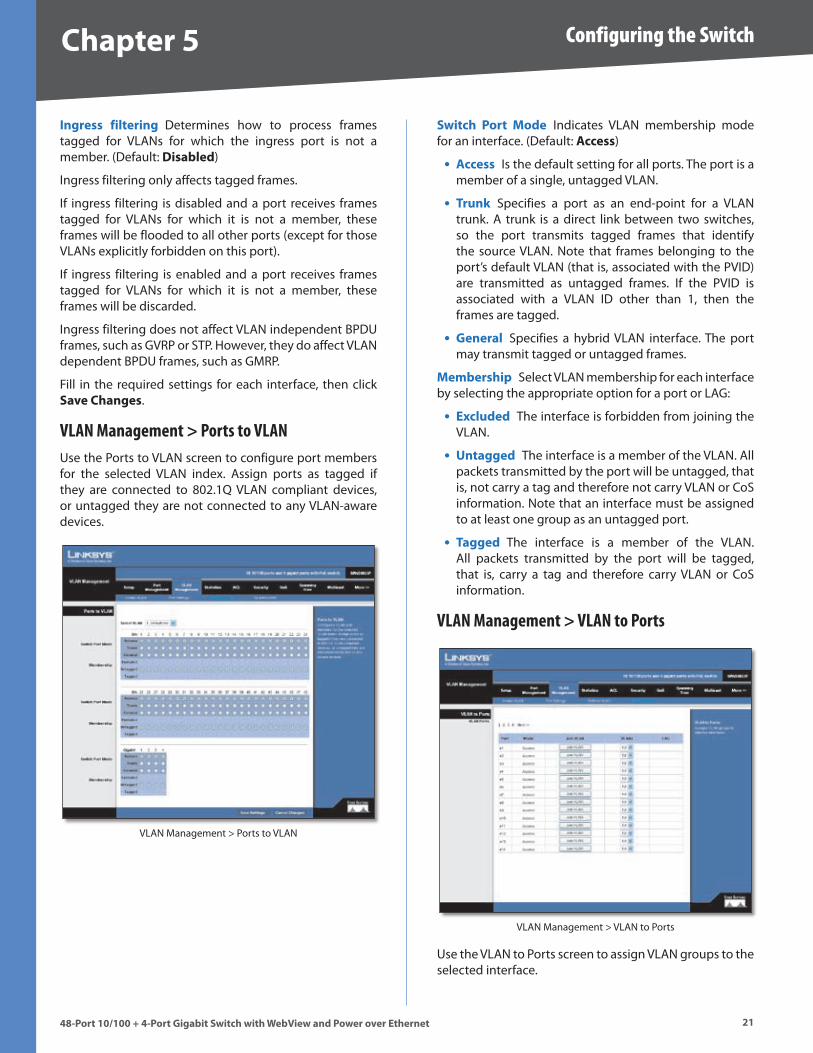
VLAN Management > Ports to VLANUse the Ports to VLAN screen to configure port members for the selected VLAN index . Assign ports as tagged if they are connected to 802 .1Q VLAN compliant devices, or untagged they are not connected to any VLAN-aware devices .
VLAN Management > Ports to VLAN
Sw�tch Port Mode Indicates VLAN membership mode for an interface . (Default: Access)
Access Is the default setting for all ports . The port is a member of a single, untagged VLAN .
Trunk Specifies a port as an end-point for a VLAN trunk . A trunk is a direct link between two switches, so the port transmits tagged frames that identify the source VLAN . Note that frames belonging to the port’s default VLAN (that is, associated with the PVID) are transmitted as untagged frames . If the PVID is associated with a VLAN ID other than 1, then the frames are tagged .
General Specifies a hybrid VLAN interface . The port may transmit tagged or untagged frames .
Membersh�p Select VLAN membership for each interface by selecting the appropriate option for a port or LAG:
Excluded The interface is forbidden from joining the VLAN .
Untagged The interface is a member of the VLAN . All packets transmitted by the port will be untagged, that is, not carry a tag and therefore not carry VLAN or CoS information . Note that an interface must be assigned to at least one group as an untagged port .
Tagged The interface is a member of the VLAN . All packets transmitted by the port will be tagged, that is, carry a tag and therefore carry VLAN or CoS information .
VLAN Management > VLAN to Ports
VLAN Management > VLAN to Ports
Use the VLAN to Ports screen to assign VLAN groups to the selected interface .
•
•
•
•
•
•
Chapter � Configuring the Switch
��48-Port 10/100 + 4-Port G�gab�t Sw�tch w�th WebV�ew and Power over Ethernet
Mode Indicates the VLAN switch port mode for the interface .
Jo�n VLAN Configures the selected interface to be a member of other VLANs .
VLANs VLANs for which the selected interface is a member .
LAG Indicates the port is a member of the specified LAG .
StatisticsYou can display standard statistics on network traffic from the Interfaces Group and Ethernet-like MIBs, as well as a detailed breakdown of traffic based on the RMON MIB . Interfaces and Ethernet-like statistics display errors on the traffic passing through each port .
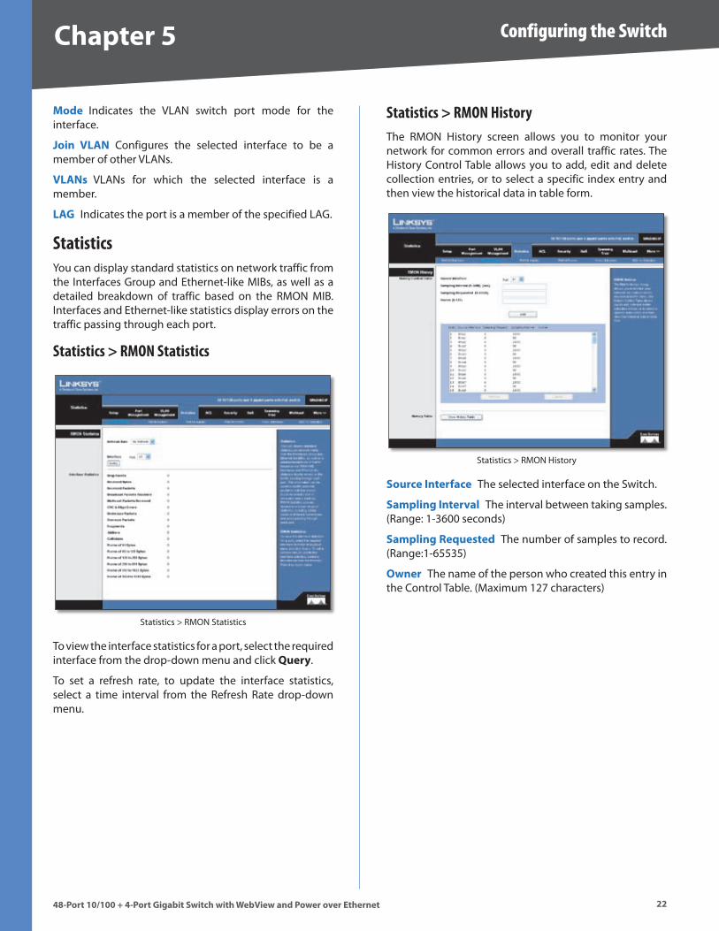
Statistics > RMON Statistics
Statistics > RMON Statistics
To view the interface statistics for a port, select the required interface from the drop-down menu and click Query .
To set a refresh rate, to update the interface statistics, select a time interval from the Refresh Rate drop-down menu .
Statistics > RMON HistoryThe RMON History screen allows you to monitor your network for common errors and overall traffic rates . The History Control Table allows you to add, edit and delete collection entries, or to select a specific index entry and then view the historical data in table form .
Statistics > RMON History
Source Interface The selected interface on the Switch .
Sampl�ng Interval The interval between taking samples . (Range: 1-3600 seconds)
Sampl�ng Requested The number of samples to record . (Range:1-65535)
Owner The name of the person who created this entry in the Control Table . (Maximum 127 characters)
Chapter � Configuring the Switch
��48-Port 10/100 + 4-Port G�gab�t Sw�tch w�th WebV�ew and Power over Ethernet
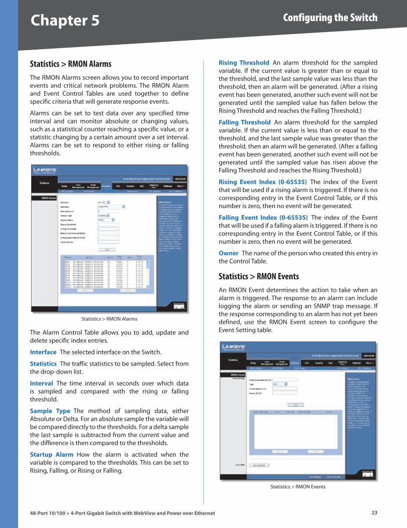
Statistics > RMON AlarmsThe RMON Alarms screen allows you to record important events and critical network problems . The RMON Alarm and Event Control Tables are used together to define specific criteria that will generate response events .
Alarms can be set to test data over any specified time interval and can monitor absolute or changing values, such as a statistical counter reaching a specific value, or a statistic changing by a certain amount over a set interval . Alarms can be set to respond to either rising or falling thresholds .
Statistics > RMON Alarms
The Alarm Control Table allows you to add, update and delete specific index entries .
Interface The selected interface on the Switch .
Stat�st�cs The traffic statistics to be sampled . Select from the drop-down list .
Interval The time interval in seconds over which data is sampled and compared with the rising or falling threshold .
Sample Type The method of sampling data, either Absolute or Delta . For an absolute sample the variable will be compared directly to the thresholds . For a delta sample the last sample is subtracted from the current value and the difference is then compared to the thresholds .
Startup Alarm How the alarm is activated when the variable is compared to the thresholds . This can be set to Rising, Falling, or Rising or Falling .
R�s�ng Threshold An alarm threshold for the sampled variable . If the current value is greater than or equal to the threshold, and the last sample value was less than the threshold, then an alarm will be generated . (After a rising event has been generated, another such event will not be generated until the sampled value has fallen below the Rising Threshold and reaches the Falling Threshold .)
Fall�ng Threshold An alarm threshold for the sampled variable . If the current value is less than or equal to the threshold, and the last sample value was greater than the threshold, then an alarm will be generated . (After a falling event has been generated, another such event will not be generated until the sampled value has risen above the Falling Threshold and reaches the Rising Threshold .)
R�s�ng Event Index (0-�����) The index of the Event that will be used if a rising alarm is triggered . If there is no corresponding entry in the Event Control Table, or if this number is zero, then no event will be generated .
Fall�ng Event Index (0-�����) The index of the Event that will be used if a falling alarm is triggered . If there is no corresponding entry in the Event Control Table, or if this number is zero, then no event will be generated .
Owner The name of the person who created this entry in the Control Table .
Statistics > RMON EventsAn RMON Event determines the action to take when an alarm is triggered . The response to an alarm can include logging the alarm or sending an SNMP trap message . If the response corresponding to an alarm has not yet been defined, use the RMON Event screen to configure the Event Setting table .
Statistics > RMON Events
Chapter � Configuring the Switch
�448-Port 10/100 + 4-Port G�gab�t Sw�tch w�th WebV�ew and Power over Ethernet
Event Descr�pt�on A text comment that describes the entry in the Event Setting Table .
Type The type of action that is taken for an alarm . This can be None, Log, Trap, or Log and Trap .
Commun�ty The SNMP community name that a trap manager must use to receive trap messages .
Owner The name of the person who created this entry in the Event Setting Table . (Maximum 127 characters) .
Click on the Add button to add an Event index entry to the table .
To display each time an event was triggered by an alarm, first highlight an entry in the Event Control Table and then click on the V�ew Log Table button . The Log Table shows the log index number, the time of an event, and the description of the event that activated the entry .
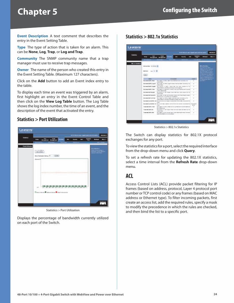
Statistics > Port Utilization
Statistics > Port Utilization
Displays the percentage of bandwidth currently utilized on each port of the Switch .
Statistics > 802.1x Statistics
Statistics > 802 .1x Statistics
The Switch can display statistics for 802 .1X protocol exchanges for any port .
To view the statistics for a port, select the required interface from the drop-down menu and click Query .
To set a refresh rate for updating the 802 .1X statistics, select a time interval from the Refresh Rate drop-down menu .
ACLAccess Control Lists (ACL) provide packet filtering for IP frames (based on address, protocol, Layer 4 protocol port number or TCP control code) or any frames (based on MAC address or Ethernet type) . To filter incoming packets, first create an access list, add the required rules, specify a mask to modify the precedence in which the rules are checked, and then bind the list to a specific port .
Chapter � Configuring the Switch
��48-Port 10/100 + 4-Port G�gab�t Sw�tch w�th WebV�ew and Power over Ethernet
ACL > IP based ACL
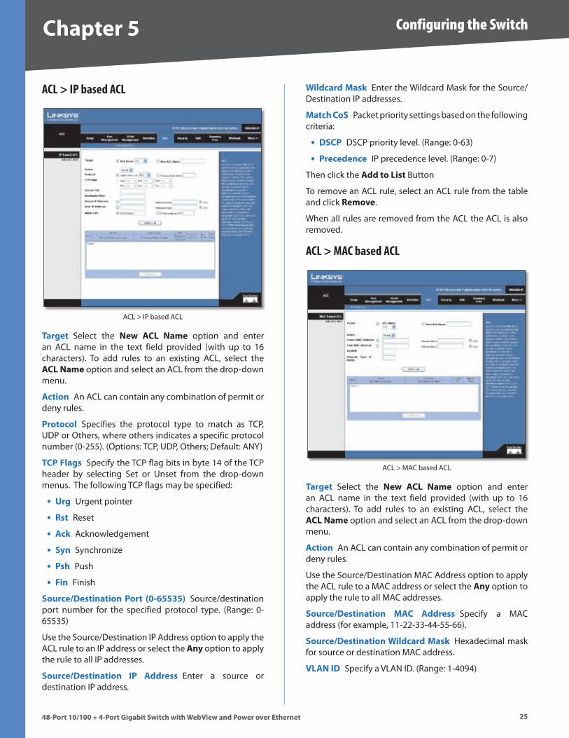
ACL > IP based ACL
Target Select the New ACL Name option and enter an ACL name in the text field provided (with up to 16 characters) . To add rules to an existing ACL, select the ACL Name option and select an ACL from the drop-down menu .
Act�on An ACL can contain any combination of permit or deny rules .
Protocol Specifies the protocol type to match as TCP, UDP or Others, where others indicates a specific protocol number (0-255) . (Options: TCP, UDP, Others; Default: ANY)
TCP Flags Specify the TCP flag bits in byte 14 of the TCP header by selecting Set or Unset from the drop-down menus . The following TCP flags may be specified:
Urg Urgent pointer
Rst Reset
Ack Acknowledgement
Syn Synchronize
Psh Push
F�n Finish
Source/Dest�nat�on Port (0-�����) Source/destination port number for the specified protocol type . (Range: 0-65535)
Use the Source/Destination IP Address option to apply the ACL rule to an IP address or select the Any option to apply the rule to all IP addresses .
Source/Dest�nat�on IP Address Enter a source or destination IP address .
•
•
•
•
•
•
W�ldcard Mask Enter the Wildcard Mask for the Source/Destination IP addresses .
Match CoS Packet priority settings based on the following criteria:
DSCP DSCP priority level . (Range: 0-63)
Precedence IP precedence level . (Range: 0-7)
Then click the Add to L�st Button
To remove an ACL rule, select an ACL rule from the table and click Remove .
When all rules are removed from the ACL the ACL is also removed .
ACL > MAC based ACL
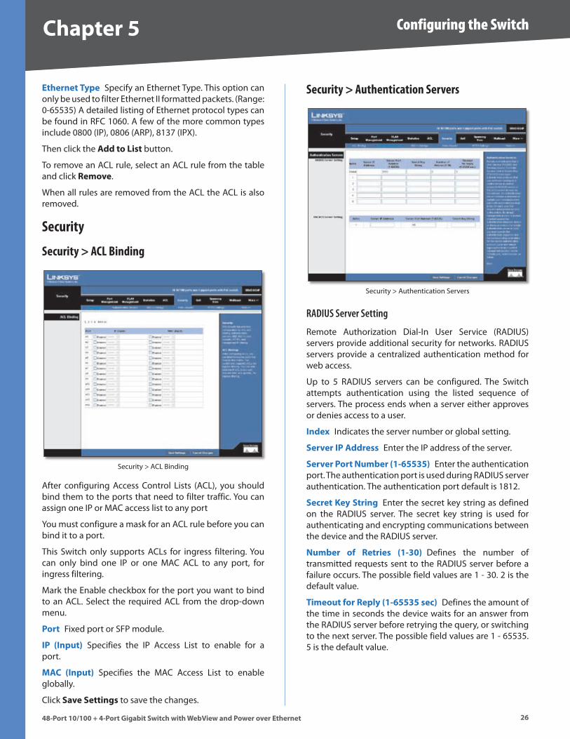
ACL > MAC based ACL
Target Select the New ACL Name option and enter an ACL name in the text field provided (with up to 16 characters) . To add rules to an existing ACL, select the ACL Name option and select an ACL from the drop-down menu .
Act�on An ACL can contain any combination of permit or deny rules .
Use the Source/Destination MAC Address option to apply the ACL rule to a MAC address or select the Any option to apply the rule to all MAC addresses .
Source/Dest�nat�on MAC Address Specify a MAC address (for example, 11-22-33-44-55-66) .
Source/Dest�nat�on W�ldcard Mask Hexadecimal mask for source or destination MAC address .
VLAN ID Specify a VLAN ID . (Range: 1-4094)
•
•
Chapter � Configuring the Switch
��48-Port 10/100 + 4-Port G�gab�t Sw�tch w�th WebV�ew and Power over Ethernet
Ethernet Type Specify an Ethernet Type . This option can only be used to filter Ethernet II formatted packets . (Range: 0-65535) A detailed listing of Ethernet protocol types can be found in RFC 1060 . A few of the more common types include 0800 (IP), 0806 (ARP), 8137 (IPX) .
Then click the Add to L�st button .
To remove an ACL rule, select an ACL rule from the table and click Remove .
When all rules are removed from the ACL the ACL is also removed .
Security
Security > ACL Binding
Security > ACL Binding
After configuring Access Control Lists (ACL), you should bind them to the ports that need to filter traffic . You can assign one IP or MAC access list to any port
You must configure a mask for an ACL rule before you can bind it to a port .
This Switch only supports ACLs for ingress filtering . You can only bind one IP or one MAC ACL to any port, for ingress filtering .
Mark the Enable checkbox for the port you want to bind to an ACL . Select the required ACL from the drop-down menu .
Port Fixed port or SFP module .
IP (Input) Specifies the IP Access List to enable for a port .
MAC (Input) Specifies the MAC Access List to enable globally .
Click Save Sett�ngs to save the changes .
Security > Authentication Servers
Security > Authentication Servers
RADIUS Server Setting
Remote Authorization Dial-In User Service (RADIUS) servers provide additional security for networks . RADIUS servers provide a centralized authentication method for web access .
Up to 5 RADIUS servers can be configured . The Switch attempts authentication using the listed sequence of servers . The process ends when a server either approves or denies access to a user .
Index Indicates the server number or global setting .
Server IP Address Enter the IP address of the server .
Server Port Number (1-�����) Enter the authentication port . The authentication port is used during RADIUS server authentication . The authentication port default is 1812 .
Secret Key Str�ng Enter the secret key string as defined on the RADIUS server . The secret key string is used for authenticating and encrypting communications between the device and the RADIUS server .
Number of Retr�es (1-�0) Defines the number of transmitted requests sent to the RADIUS server before a failure occurs . The possible field values are 1 - 30 . 2 is the default value .
T�meout for Reply (1-����� sec) Defines the amount of the time in seconds the device waits for an answer from the RADIUS server before retrying the query, or switching to the next server . The possible field values are 1 - 65535 . 5 is the default value .
Chapter � Configuring the Switch
��48-Port 10/100 + 4-Port G�gab�t Sw�tch w�th WebV�ew and Power over Ethernet
TACACS Server Setting
The Switch provides Terminal Access Controller Access Control System (TACACS+) client support . TACACS+ provides centralized security for validation of users accessing the device . TACACS+ provides a centralized user management system, while still retaining consistency with RADIUS and other authentication processes . The TACACS+ protocol ensures network integrity through encrypted protocol exchanges between the device and TACACS+ server .
Server IP Address Enter the TACACS+ Server IP address .
Server Port Number (1-�����) Defines the port number through which the TACACS+ session occurs . The default port is 49 .
Secret Key Str�ng Defines the authentication and encryption key for TACACS+ server . The key must match the encryption key used on the TACACS+ server .
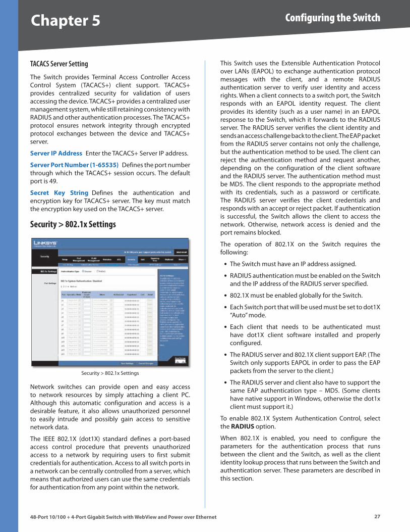
Security > 802.1x Settings
Security > 802 .1x Settings
Network switches can provide open and easy access to network resources by simply attaching a client PC . Although this automatic configuration and access is a desirable feature, it also allows unauthorized personnel to easily intrude and possibly gain access to sensitive network data .
The IEEE 802 .1X (dot1X) standard defines a port-based access control procedure that prevents unauthorized access to a network by requiring users to first submit credentials for authentication . Access to all switch ports in a network can be centrally controlled from a server, which means that authorized users can use the same credentials for authentication from any point within the network .
This Switch uses the Extensible Authentication Protocol over LANs (EAPOL) to exchange authentication protocol messages with the client, and a remote RADIUS authentication server to verify user identity and access rights . When a client connects to a switch port, the Switch responds with an EAPOL identity request . The client provides its identity (such as a user name) in an EAPOL response to the Switch, which it forwards to the RADIUS server . The RADIUS server verifies the client identity and sends an access challenge back to the client . The EAP packet from the RADIUS server contains not only the challenge, but the authentication method to be used . The client can reject the authentication method and request another, depending on the configuration of the client software and the RADIUS server . The authentication method must be MD5 . The client responds to the appropriate method with its credentials, such as a password or certificate . The RADIUS server verifies the client credentials and responds with an accept or reject packet . If authentication is successful, the Switch allows the client to access the network . Otherwise, network access is denied and the port remains blocked .
The operation of 802 .1X on the Switch requires the following:
The Switch must have an IP address assigned .
RADIUS authentication must be enabled on the Switch and the IP address of the RADIUS server specified .
802 .1X must be enabled globally for the Switch .
Each Switch port that will be used must be set to dot1X “Auto” mode .
Each client that needs to be authenticated must have dot1X client software installed and properly configured .
The RADIUS server and 802 .1X client support EAP . (The Switch only supports EAPOL in order to pass the EAP packets from the server to the client .)
The RADIUS server and client also have to support the same EAP authentication type – MD5 . (Some clients have native support in Windows, otherwise the dot1x client must support it .)
To enable 802 .1X System Authentication Control, select the RADIUS option .
When 802 .1X is enabled, you need to configure the parameters for the authentication process that runs between the client and the Switch, as well as the client identity lookup process that runs between the Switch and authentication server . These parameters are described in this section .
•
•
•
•
•
•
•
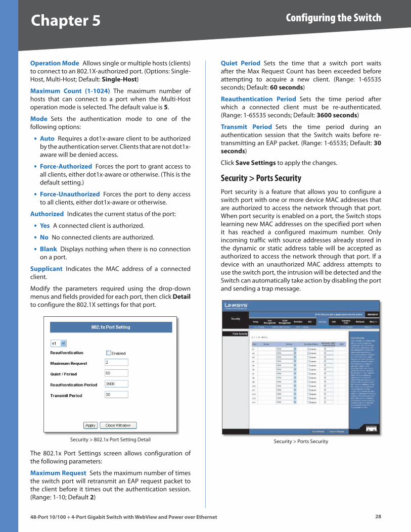
Chapter � Configuring the Switch
�848-Port 10/100 + 4-Port G�gab�t Sw�tch w�th WebV�ew and Power over Ethernet
Operat�on Mode Allows single or multiple hosts (clients) to connect to an 802 .1X-authorized port . (Options: Single-Host, Multi-Host; Default: S�ngle-Host)
Max�mum Count (1-10�4) The maximum number of hosts that can connect to a port when the Multi-Host operation mode is selected . The default value is � .
Mode Sets the authentication mode to one of the following options:
Auto Requires a dot1x-aware client to be authorized by the authentication server . Clients that are not dot1x-aware will be denied access .
Force-Author�zed Forces the port to grant access to all clients, either dot1x-aware or otherwise . (This is the default setting .)
Force-Unauthor�zed Forces the port to deny access to all clients, either dot1x-aware or otherwise .
Author�zed Indicates the current status of the port:
Yes A connected client is authorized .
No No connected clients are authorized .
Blank Displays nothing when there is no connection on a port .
Suppl�cant Indicates the MAC address of a connected client .
Modify the parameters required using the drop-down menus and fields provided for each port, then click Deta�l to configure the 802 .1X settings for that port .
Security > 802 .1x Port Setting Detail
The 802 .1x Port Settings screen allows configuration of the following parameters:
Max�mum Request Sets the maximum number of times the switch port will retransmit an EAP request packet to the client before it times out the authentication session . (Range: 1-10; Default �)
•
•
•
•
•
•
Qu�et Per�od Sets the time that a switch port waits after the Max Request Count has been exceeded before attempting to acquire a new client . (Range: 1-65535 seconds; Default: �0 seconds)
Reauthent�cat�on Per�od Sets the time period after which a connected client must be re-authenticated . (Range: 1-65535 seconds; Default: ��00 seconds)
Transm�t Per�od Sets the time period during an authentication session that the Switch waits before re-transmitting an EAP packet . (Range: 1-65535; Default: �0 seconds)
Click Save Sett�ngs to apply the changes .
Security > Ports SecurityPort security is a feature that allows you to configure a switch port with one or more device MAC addresses that are authorized to access the network through that port . When port security is enabled on a port, the Switch stops learning new MAC addresses on the specified port when it has reached a configured maximum number . Only incoming traffic with source addresses already stored in the dynamic or static address table will be accepted as authorized to access the network through that port . If a device with an unauthorized MAC address attempts to use the switch port, the intrusion will be detected and the Switch can automatically take action by disabling the port and sending a trap message .
Security > Ports Security
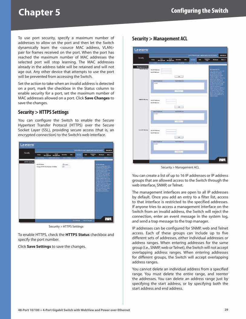
Chapter � Configuring the Switch
��48-Port 10/100 + 4-Port G�gab�t Sw�tch w�th WebV�ew and Power over Ethernet
To use port security, specify a maximum number of addresses to allow on the port and then let the Switch dynamically learn the <source MAC address, VLAN> pair for frames received on the port . When the port has reached the maximum number of MAC addresses the selected port will stop learning . The MAC addresses already in the address table will be retained and will not age out . Any other device that attempts to use the port will be prevented from accessing the Switch .
Set the action to take when an invalid address is detected on a port, mark the checkbox in the Status column to enable security for a port, set the maximum number of MAC addresses allowed on a port . Click Save Changes to save the changes .
Security > HTTPS SettingsYou can configure the Switch to enable the Secure Hypertext Transfer Protocol (HTTPS) over the Secure Socket Layer (SSL), providing secure access (that is, an encrypted connection) to the Switch’s web interface .
Security > HTTPS Settings
To enable HTTPS, check the HTTPS Status checkbox and specify the port number .
Click Save Sett�ngs to save the changes .
Security > Management ACL
Security > Management ACL
You can create a list of up to 16 IP addresses or IP address groups that are allowed access to the Switch through the web interface, SNMP, or Telnet .
The management interfaces are open to all IP addresses by default . Once you add an entry to a filter list, access to that interface is restricted to the specified addresses . If anyone tries to access a management interface on the Switch from an invalid address, the Switch will reject the connection, enter an event message in the system log, and send a trap message to the trap manager .
IP addresses can be configured for SNMP, web and Telnet access . Each of these groups can include up to five different sets of addresses, either individual addresses or address ranges . When entering addresses for the same group (i .e ., SNMP, web or Telnet), the Switch will not accept overlapping address ranges . When entering addresses for different groups, the Switch will accept overlapping address ranges .
You cannot delete an individual address from a specified range . You must delete the entire range, and reenter the addresses . You can delete an address range just by specifying the start address, or by specifying both the start address and end address .
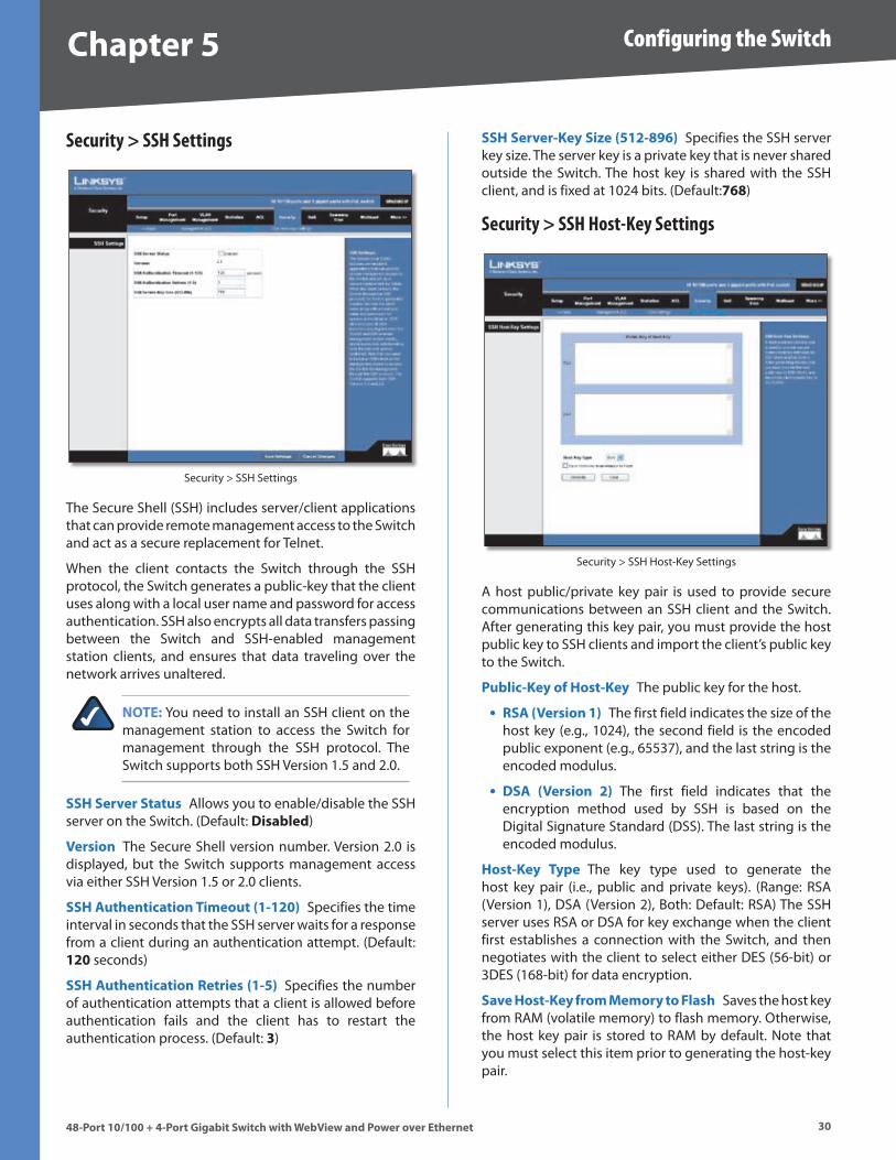
Chapter � Configuring the Switch
�048-Port 10/100 + 4-Port G�gab�t Sw�tch w�th WebV�ew and Power over Ethernet
Security > SSH Settings
Security > SSH Settings
The Secure Shell (SSH) includes server/client applications that can provide remote management access to the Switch and act as a secure replacement for Telnet .
When the client contacts the Switch through the SSH protocol, the Switch generates a public-key that the client uses along with a local user name and password for access authentication . SSH also encrypts all data transfers passing between the Switch and SSH-enabled management station clients, and ensures that data traveling over the network arrives unaltered .
NOTE: You need to install an SSH client on the management station to access the Switch for management through the SSH protocol . The Switch supports both SSH Version 1 .5 and 2 .0 .
SSH Server Status Allows you to enable/disable the SSH server on the Switch . (Default: D�sabled)
Vers�on The Secure Shell version number . Version 2 .0 is displayed, but the Switch supports management access via either SSH Version 1 .5 or 2 .0 clients .
SSH Authent�cat�on T�meout (1-1�0) Specifies the time interval in seconds that the SSH server waits for a response from a client during an authentication attempt . (Default: 1�0 seconds)
SSH Authent�cat�on Retr�es (1-�) Specifies the number of authentication attempts that a client is allowed before authentication fails and the client has to restart the authentication process . (Default: �)
SSH Server-Key S�ze (�1�-8��) Specifies the SSH server key size . The server key is a private key that is never shared outside the Switch . The host key is shared with the SSH client, and is fixed at 1024 bits . (Default:��8)
Security > SSH Host-Key Settings
Security > SSH Host-Key Settings
A host public/private key pair is used to provide secure communications between an SSH client and the Switch . After generating this key pair, you must provide the host public key to SSH clients and import the client’s public key to the Switch .
Publ�c-Key of Host-Key The public key for the host .
RSA (Vers�on 1) The first field indicates the size of the host key (e .g ., 1024), the second field is the encoded public exponent (e .g ., 65537), and the last string is the encoded modulus .
DSA (Vers�on �) The first field indicates that the encryption method used by SSH is based on the Digital Signature Standard (DSS) . The last string is the encoded modulus .
Host-Key Type The key type used to generate the host key pair (i .e ., public and private keys) . (Range: RSA (Version 1), DSA (Version 2), Both: Default: RSA) The SSH server uses RSA or DSA for key exchange when the client first establishes a connection with the Switch, and then negotiates with the client to select either DES (56-bit) or 3DES (168-bit) for data encryption .
Save Host-Key from Memory to Flash Saves the host key from RAM (volatile memory) to flash memory . Otherwise, the host key pair is stored to RAM by default . Note that you must select this item prior to generating the host-key pair .
•
•
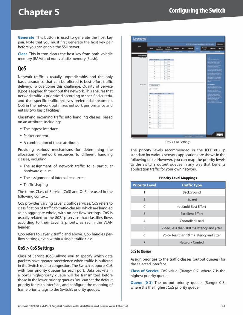
Chapter � Configuring the Switch
�148-Port 10/100 + 4-Port G�gab�t Sw�tch w�th WebV�ew and Power over Ethernet
Generate This button is used to generate the host key pair . Note that you must first generate the host key pair before you can enable the SSH server .
Clear This button clears the host key from both volatile memory (RAM) and non-volatile memory (Flash) .
QoSNetwork traffic is usually unpredictable, and the only basic assurance that can be offered is best effort traffic delivery . To overcome this challenge, Quality of Service (QoS) is applied throughout the network . This ensures that network traffic is prioritized according to specified criteria, and that specific traffic receives preferential treatment . QoS in the network optimizes network performance and entails two basic facilities:
Classifying incoming traffic into handling classes, based on an attribute, including:
The ingress interface
Packet content
A combination of these attributes
Providing various mechanisms for determining the allocation of network resources to different handling classes, including:
The assignment of network traffic to a particular hardware queue
The assignment of internal resources
Traffic shaping
The terms Class of Service (CoS) and QoS are used in the following context:
CoS provides varying Layer 2 traffic services . CoS refers to classification of traffic to traffic-classes, which are handled as an aggregate whole, with no per-flow settings . CoS is usually related to the 802 .1p service that classifies flows according to their Layer 2 priority, as set in the VLAN header .
QoS refers to Layer 2 traffic and above . QoS handles per-flow settings, even within a single traffic class .
QoS > CoS SettingsClass of Service (CoS) allows you to specify which data packets have greater precedence when traffic is buffered in the Switch due to congestion . The Switch supports CoS with four priority queues for each port . Data packets in a port’s high-priority queue will be transmitted before those in the lower-priority queues . You can set the default priority for each interface, and configure the mapping of frame priority tags to the Switch’s priority queues .
•
•
•
•
•
•
QoS > Cos Settings
The priority levels recommended in the IEEE 802 .1p standard for various network applications are shown in the following table . However, you can map the priority levels to the Switch’s output queues in any way that benefits application traffic for your own network .
Pr�or�ty Level Mapp�ngs
Pr�or�ty Level Traff�c Type
1 Background
2 (Spare)
0 (default) Best Effort
3 Excellent Effort
4 Controlled Load
5 Video, less than 100 ms latency and jitter
6 Voice, less than 10 ms latency and jitter
7 Network Control
CoS to Queue
Assign priorities to the traffic classes (output queues) for the selected interface .
Class of Serv�ce CoS value . (Range: 0-7, where 7 is the highest priority queue)
Queue (0-�) The output priority queue . (Range: 0-3, where 3 is the highest CoS priority queue)
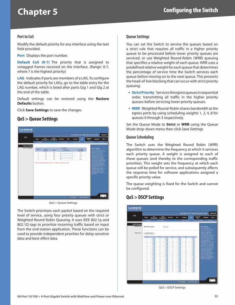
Chapter � Configuring the Switch
��48-Port 10/100 + 4-Port G�gab�t Sw�tch w�th WebV�ew and Power over Ethernet
Port to CoS
Modify the default priority for any interface using the text field provided .
Port Displays the port number .
Default CoS (0-�) The priority that is assigned to untagged frames received on the interface . (Range: 0-7, where 7 is the highest priority)
LAG Indicates if ports are members of a LAG . To configure the default priority for LAGs, go to the table entry for the LAG number, which is listed after ports Gig 1 and Gig 2 at the end of the table .
Default settings can be restored using the Restore Defaults button .
Click Save Sett�ngs to save the changes .
QoS > Queue Settings
QoS > Queue Settings
The Switch prioritizes each packet based on the required level of service, using four priority queues with strict or Weighted Round Robin Queuing . It uses IEEE 802 .1p and 802 .1Q tags to prioritize incoming traffic based on input from the end-station application . These functions can be used to provide independent priorities for delay-sensitive data and best-effort data .
Queue Settings
You can set the Switch to service the queues based on a strict rule that requires all traffic in a higher priority queue to be processed before lower priority queues are serviced, or use Weighted Round-Robin (WRR) queuing that specifies a relative weight of each queue . WRR uses a predefined relative weight for each queue that determines the percentage of service time the Switch services each queue before moving on to the next queue . This prevents the head-of-line blocking that can occur with strict priority queuing .
Str�ct Pr�or�ty Services the egress queues in sequential order, transmitting all traffic in the higher priority queues before servicing lower priority queues .
WRR Weighted Round-Robin shares bandwidth at the egress ports by using scheduling weights 1, 2, 4, 8 for queues 0 through 3 respectively .
Set the Queue Mode to Str�ct or WRR using the Queue Mode drop-down menu then click Save Settings
Queue Scheduling
The Switch uses the Weighted Round Robin (WRR) algorithm to determine the frequency at which it services each priority queue . A weight is assigned to each of these queues (and thereby to the corresponding traffic priorities) . This weight sets the frequency at which each queue will be polled for service, and subsequently affects the response time for software applications assigned a specific priority value .
The queue weighting is fixed for the Switch and cannot be configured .
QoS > DSCP Settings
QoS > DSCP Settings
•
•
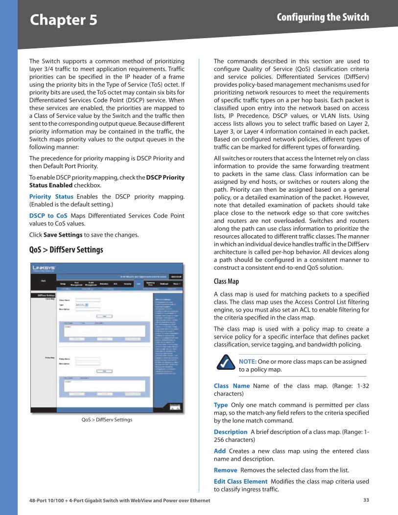
Chapter � Configuring the Switch
��48-Port 10/100 + 4-Port G�gab�t Sw�tch w�th WebV�ew and Power over Ethernet
The Switch supports a common method of prioritizing layer 3/4 traffic to meet application requirements . Traffic priorities can be specified in the IP header of a frame using the priority bits in the Type of Service (ToS) octet . If priority bits are used, the ToS octet may contain six bits for Differentiated Services Code Point (DSCP) service . When these services are enabled, the priorities are mapped to a Class of Service value by the Switch and the traffic then sent to the corresponding output queue . Because different priority information may be contained in the traffic, the Switch maps priority values to the output queues in the following manner:
The precedence for priority mapping is DSCP Priority and then Default Port Priority .
To enable DSCP priority mapping, check the DSCP Pr�or�ty Status Enabled checkbox .
Pr�or�ty Status Enables the DSCP priority mapping . (Enabled is the default setting .)
DSCP to CoS Maps Differentiated Services Code Point values to CoS values .
Click Save Sett�ngs to save the changes .
QoS > DiffServ Settings
QoS > DiffServ Settings
The commands described in this section are used to configure Quality of Service (QoS) classification criteria and service policies . Differentiated Services (DiffServ) provides policy-based management mechanisms used for prioritizing network resources to meet the requirements of specific traffic types on a per hop basis . Each packet is classified upon entry into the network based on access lists, IP Precedence, DSCP values, or VLAN lists . Using access lists allows you to select traffic based on Layer 2, Layer 3, or Layer 4 information contained in each packet . Based on configured network policies, different types of traffic can be marked for different types of forwarding .
All switches or routers that access the Internet rely on class information to provide the same forwarding treatment to packets in the same class . Class information can be assigned by end hosts, or switches or routers along the path . Priority can then be assigned based on a general policy, or a detailed examination of the packet . However, note that detailed examination of packets should take place close to the network edge so that core switches and routers are not overloaded . Switches and routers along the path can use class information to prioritize the resources allocated to different traffic classes . The manner in which an individual device handles traffic in the DiffServ architecture is called per-hop behavior . All devices along a path should be configured in a consistent manner to construct a consistent end-to-end QoS solution .
Class Map
A class map is used for matching packets to a specified class . The class map uses the Access Control List filtering engine, so you must also set an ACL to enable filtering for the criteria specified in the class map .
The class map is used with a policy map to create a service policy for a specific interface that defines packet classification, service tagging, and bandwidth policing .
NOTE: One or more class maps can be assigned to a policy map .
Class Name Name of the class map . (Range: 1-32 characters)
Type Only one match command is permitted per class map, so the match-any field refers to the criteria specified by the lone match command .
Descr�pt�on A brief description of a class map . (Range: 1-256 characters)
Add Creates a new class map using the entered class name and description .
Remove Removes the selected class from the list .
Ed�t Class Element Modifies the class map criteria used to classify ingress traffic .

Chapter � Configuring the Switch
�448-Port 10/100 + 4-Port G�gab�t Sw�tch w�th WebV�ew and Power over Ethernet
Select the entry from the table that you wish to change, then click Ed�t Class Element . Add rules to a selected class using the ACL list drop-down menu or the IP DSCP, IP Precedence and VLAN text fields provided, then click Add .
QoS > DiffServ Settings > Edit Class Element
Class Rule Edits the rules for the class by specifying the type of traffic based on an access list, a DSCP or IP Precedence value, or a VLAN .
ACL Name of an access control list . Any type of ACL can be specified, including standard or extended IP ACLs and MAC ACLs . (Range: 1-16 characters)
IP DSCP A DSCP value . (Range: 0-63)
IP Precedence An IP Precedence value . (Range: 0-7)
VLAN A VLAN value . (Range: 1-4094)
Add Adds the specified criteria to the class . Only one entry is permitted per class .
Remove Deletes the selected criteria from the class .
Policy Map
A policy map can contain multiple class statements that can be applied to the same interface with the Service Policy Settings . You can configure up to 63 policers (that is, class maps) for Fast Ethernet and Gigabit Ethernet ingress ports .
QoS > DiffServ Settings > Edit Policy Element
Policing is based on a token bucket, where bucket depth (that is, the maximum burst before the bucket overflows) is by specified the “Burst” field, and the average rate tokens are removed from the bucket is by specified by the “Rate” option .
After using the policy map to define packet classification, service tagging, and bandwidth policing, it must be assigned to a specific interface by a service policy to take effect .
Pol�cy name The name of the policy map . (Range: 1-32 characters for the name)
Descr�pt�on A brief description of the Policy . (Range 1-256 characters for the description)
Click Add to create a new policy, or select a policy and click “Edit Policy Element” to change the policy rules of the selected policy, or Remove Policy to delete the policy .
Class Name Name of class map . Use the drop-down menu to select a different policy .
Act�on Configures the service provided to ingress traffic by setting a CoS, DSCP, or IP Precedence value in a matching packet . (Range - CoS: 0-7, DSCP: 0-63, IP Precedence: 0-7)
Enable Meter Check this to define the maximum throughput, burst rate, and the action that results from a policy violation .
Rate (kbps) Rate in kilobits per second . (Range: 1-100000 kbps or maximum port speed, whichever is lower)
Burst (byte) Burst in bytes . (Range: 64-1522)
•
•
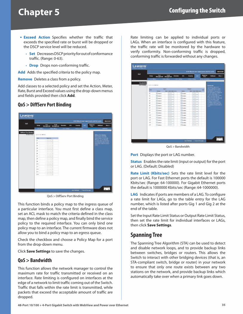
Chapter � Configuring the Switch
��48-Port 10/100 + 4-Port G�gab�t Sw�tch w�th WebV�ew and Power over Ethernet
Exceed Act�on Specifies whether the traffic that exceeds the specified rate or burst will be dropped or the DSCP service level will be reduced .
Set Decreases DSCP priority for out of conformance traffic . (Range: 0-63) .
Drop Drops non-conforming traffic .
Add Adds the specified criteria to the policy map .
Remove Deletes a class from a policy .
Add classes to a selected policy and set the Action, Meter, Rate, Burst and Exceed values using the drop-down menus and fields provided then click Add .
QoS > DiffServ Port Binding
QoS > DiffServ Port Binding
This function binds a policy map to the ingress queue of a particular interface . You must first define a class map, set an ACL mask to match the criteria defined in the class map, then define a policy map, and finally bind the service policy to the required interface . You can only bind one policy map to an interface . The current firmware does not allow you to bind a policy map to an egress queue .
Check the checkbox and choose a Policy Map for a port from the drop-down menu .
Click Save Sett�ngs to save the changes .
QoS > BandwidthThis function allows the network manager to control the maximum rate for traffic transmitted or received on an interface . Rate limiting is configured on interfaces at the edge of a network to limit traffic coming out of the Switch . Traffic that falls within the rate limit is transmitted, while packets that exceed the acceptable amount of traffic are dropped .
•
•
•
Rate limiting can be applied to individual ports or LAGs . When an interface is configured with this feature, the traffic rate will be monitored by the hardware to verify conformity . Non-conforming traffic is dropped, conforming traffic is forwarded without any changes .
QoS > Bandwidth
Port Displays the port or LAG number .
Status Enables the rate limit (input or output) for the port or LAG . (Default: Disabled)
Rate L�m�t (Kb�ts/sec) Sets the rate limit level for the port or LAG . For Fast Ethernet ports the default is 100000 Kbits/sec (Range: 64-100000) . For Gigabit Ethernet ports the default is 1000000 Kbits/sec (Range: 64-1000000) .
LAG Indicates if ports are members of a LAG . To configure a rate limit for LAGs, go to the table entry for the LAG number, which is listed after ports Gig 1 and Gig 2 at the end of the table .
Set the Input Rate Limit Status or Output Rate Limit Status, then set the rate limit for individual interfaces or LAGs, then click Save Sett�ngs .
Spanning TreeThe Spanning Tree Algorithm (STA) can be used to detect and disable network loops, and to provide backup links between switches, bridges or routers . This allows the Switch to interact with other bridging devices (that is, an STA-compliant switch, bridge or router) in your network to ensure that only one route exists between any two stations on the network, and provide backup links which automatically take over when a primary link goes down .
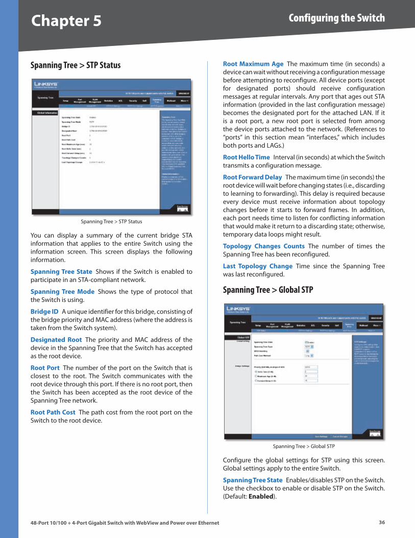
Chapter � Configuring the Switch
��48-Port 10/100 + 4-Port G�gab�t Sw�tch w�th WebV�ew and Power over Ethernet
Spanning Tree > STP Status
Spanning Tree > STP Status
You can display a summary of the current bridge STA information that applies to the entire Switch using the information screen . This screen displays the following information .
Spann�ng Tree State Shows if the Switch is enabled to participate in an STA-compliant network .
Spann�ng Tree Mode Shows the type of protocol that the Switch is using .
Br�dge ID A unique identifier for this bridge, consisting of the bridge priority and MAC address (where the address is taken from the Switch system) .
Des�gnated Root The priority and MAC address of the device in the Spanning Tree that the Switch has accepted as the root device .
Root Port The number of the port on the Switch that is closest to the root . The Switch communicates with the root device through this port . If there is no root port, then the Switch has been accepted as the root device of the Spanning Tree network .
Root Path Cost The path cost from the root port on the Switch to the root device .
Root Max�mum Age The maximum time (in seconds) a device can wait without receiving a configuration message before attempting to reconfigure . All device ports (except for designated ports) should receive configuration messages at regular intervals . Any port that ages out STA information (provided in the last configuration message) becomes the designated port for the attached LAN . If it is a root port, a new root port is selected from among the device ports attached to the network . (References to “ports” in this section mean “interfaces,” which includes both ports and LAGs .)
Root Hello T�me Interval (in seconds) at which the Switch transmits a configuration message .
Root Forward Delay The maximum time (in seconds) the root device will wait before changing states (i .e ., discarding to learning to forwarding) . This delay is required because every device must receive information about topology changes before it starts to forward frames . In addition, each port needs time to listen for conflicting information that would make it return to a discarding state; otherwise, temporary data loops might result .
Topology Changes Counts The number of times the Spanning Tree has been reconfigured .
Last Topology Change Time since the Spanning Tree was last reconfigured .
Spanning Tree > Global STP
Spanning Tree > Global STP
Configure the global settings for STP using this screen . Global settings apply to the entire Switch .
Spann�ng Tree State Enables/disables STP on the Switch . Use the checkbox to enable or disable STP on the Switch . (Default: Enabled) .
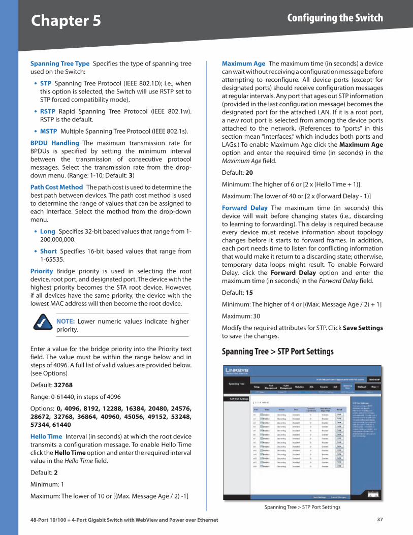
Chapter � Configuring the Switch
��48-Port 10/100 + 4-Port G�gab�t Sw�tch w�th WebV�ew and Power over Ethernet
Spann�ng Tree Type Specifies the type of spanning tree used on the Switch:
STP Spanning Tree Protocol (IEEE 802 .1D); i .e ., when this option is selected, the Switch will use RSTP set to STP forced compatibility mode) .
RSTP Rapid Spanning Tree Protocol (IEEE 802 .1w) . RSTP is the default .
MSTP Multiple Spanning Tree Protocol (IEEE 802 .1s) .
BPDU Handl�ng The maximum transmission rate for BPDUs is specified by setting the minimum interval between the transmission of consecutive protocol messages . Select the transmission rate from the drop-down menu . (Range: 1-10; Default: �)
Path Cost Method The path cost is used to determine the best path between devices . The path cost method is used to determine the range of values that can be assigned to each interface . Select the method from the drop-down menu .
Long Specifies 32-bit based values that range from 1-200,000,000 .
Short Specifies 16-bit based values that range from 1-65535 .
Pr�or�ty Bridge priority is used in selecting the root device, root port, and designated port . The device with the highest priority becomes the STA root device . However, if all devices have the same priority, the device with the lowest MAC address will then become the root device .
NOTE: Lower numeric values indicate higher priority .
Enter a value for the bridge priority into the Priority text field . The value must be within the range below and in steps of 4096 . A full list of valid values are provided below . (see Options)
Default: ����8
Range: 0-61440, in steps of 4096
Options: 0, 40��, 81��, 1��88, 1��84, �0480, �4���, �8���, ����8, ��8�4, 40��0, 4�0��, 4�1��, ���48, ���44, �1440
Hello T�me Interval (in seconds) at which the root device transmits a configuration message . To enable Hello Time click the Hello T�me option and enter the required interval value in the Hello Time field .
Default: �
Minimum: 1
Maximum: The lower of 10 or [(Max . Message Age / 2) -1]
•
•
•
•
•
Max�mum Age The maximum time (in seconds) a device can wait without receiving a configuration message before attempting to reconfigure . All device ports (except for designated ports) should receive configuration messages at regular intervals . Any port that ages out STP information (provided in the last configuration message) becomes the designated port for the attached LAN . If it is a root port, a new root port is selected from among the device ports attached to the network . (References to “ports” in this section mean “interfaces,” which includes both ports and LAGs .) To enable Maximum Age click the Max�mum Age option and enter the required time (in seconds) in the Maximum Age field .
Default: �0
Minimum: The higher of 6 or [2 x (Hello Time + 1)] .
Maximum: The lower of 40 or [2 x (Forward Delay - 1)]
Forward Delay The maximum time (in seconds) this device will wait before changing states (i .e ., discarding to learning to forwarding) . This delay is required because every device must receive information about topology changes before it starts to forward frames . In addition, each port needs time to listen for conflicting information that would make it return to a discarding state; otherwise, temporary data loops might result . To enable Forward Delay, click the Forward Delay option and enter the maximum time (in seconds) in the Forward Delay field .
Default: 1�
Minimum: The higher of 4 or [(Max . Message Age / 2) + 1]
Maximum: 30
Modify the required attributes for STP . Click Save Sett�ngs to save the changes .
Spanning Tree > STP Port Settings
Spanning Tree > STP Port Settings
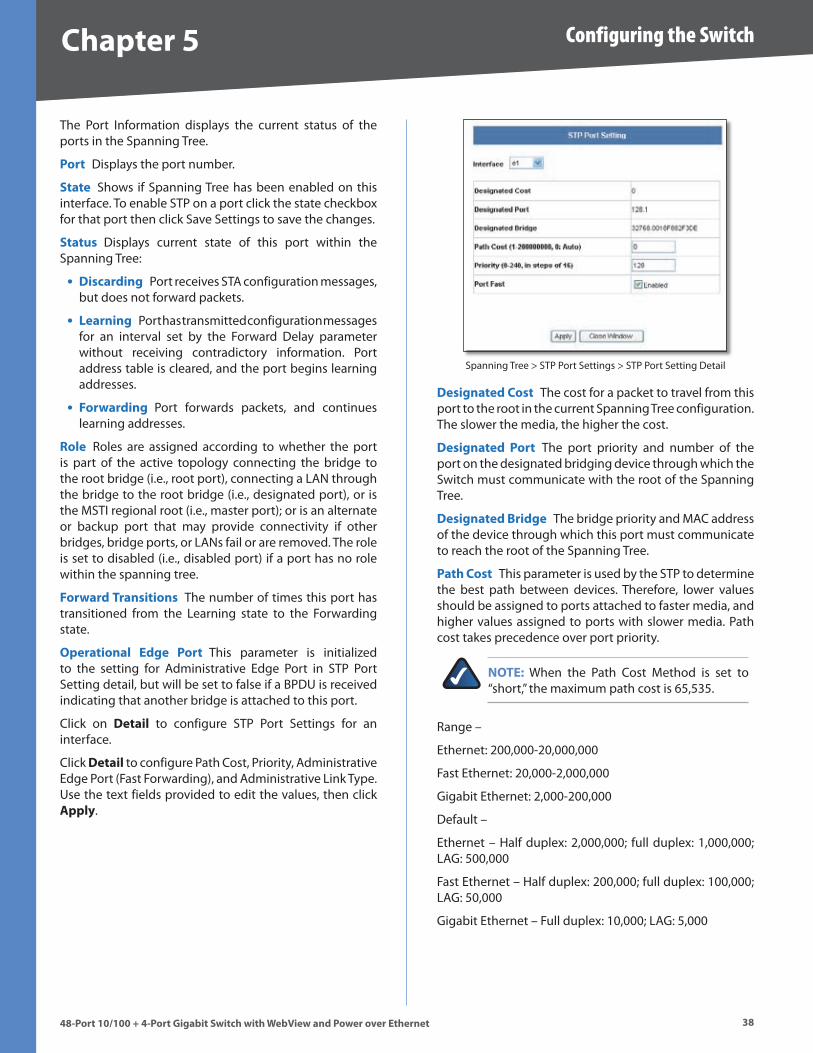
Chapter � Configuring the Switch
�848-Port 10/100 + 4-Port G�gab�t Sw�tch w�th WebV�ew and Power over Ethernet
The Port Information displays the current status of the ports in the Spanning Tree .
Port Displays the port number .
State Shows if Spanning Tree has been enabled on this interface . To enable STP on a port click the state checkbox for that port then click Save Settings to save the changes .
Status Displays current state of this port within the Spanning Tree:
D�scard�ng Port receives STA configuration messages, but does not forward packets .
Learn�ng Port has transmitted configuration messages for an interval set by the Forward Delay parameter without receiving contradictory information . Port address table is cleared, and the port begins learning addresses .
Forward�ng Port forwards packets, and continues learning addresses .
Role Roles are assigned according to whether the port is part of the active topology connecting the bridge to the root bridge (i .e ., root port), connecting a LAN through the bridge to the root bridge (i .e ., designated port), or is the MSTI regional root (i .e ., master port); or is an alternate or backup port that may provide connectivity if other bridges, bridge ports, or LANs fail or are removed . The role is set to disabled (i .e ., disabled port) if a port has no role within the spanning tree .
Forward Trans�t�ons The number of times this port has transitioned from the Learning state to the Forwarding state .
Operat�onal Edge Port This parameter is initialized to the setting for Administrative Edge Port in STP Port Setting detail, but will be set to false if a BPDU is received indicating that another bridge is attached to this port .
Click on Deta�l to configure STP Port Settings for an interface .
Click Deta�l to configure Path Cost, Priority, Administrative Edge Port (Fast Forwarding), and Administrative Link Type . Use the text fields provided to edit the values, then click Apply .
•
•
•
Spanning Tree > STP Port Settings > STP Port Setting Detail
Des�gnated Cost The cost for a packet to travel from this port to the root in the current Spanning Tree configuration . The slower the media, the higher the cost .
Des�gnated Port The port priority and number of the port on the designated bridging device through which the Switch must communicate with the root of the Spanning Tree .
Des�gnated Br�dge The bridge priority and MAC address of the device through which this port must communicate to reach the root of the Spanning Tree .
Path Cost This parameter is used by the STP to determine the best path between devices . Therefore, lower values should be assigned to ports attached to faster media, and higher values assigned to ports with slower media . Path cost takes precedence over port priority .
NOTE: When the Path Cost Method is set to “short,” the maximum path cost is 65,535 .
Range –
Ethernet: 200,000-20,000,000
Fast Ethernet: 20,000-2,000,000
Gigabit Ethernet: 2,000-200,000
Default –
Ethernet – Half duplex: 2,000,000; full duplex: 1,000,000; LAG: 500,000
Fast Ethernet – Half duplex: 200,000; full duplex: 100,000; LAG: 50,000
Gigabit Ethernet – Full duplex: 10,000; LAG: 5,000
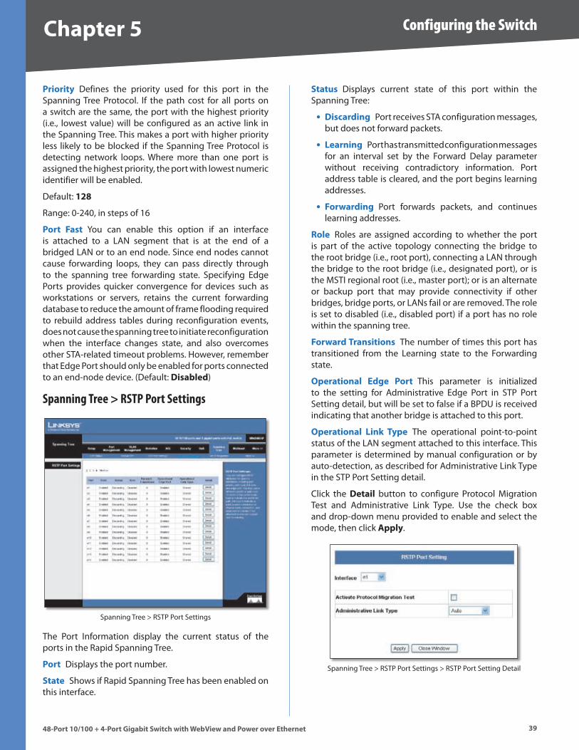
Chapter � Configuring the Switch
��48-Port 10/100 + 4-Port G�gab�t Sw�tch w�th WebV�ew and Power over Ethernet
Pr�or�ty Defines the priority used for this port in the Spanning Tree Protocol . If the path cost for all ports on a switch are the same, the port with the highest priority (i .e ., lowest value) will be configured as an active link in the Spanning Tree . This makes a port with higher priority less likely to be blocked if the Spanning Tree Protocol is detecting network loops . Where more than one port is assigned the highest priority, the port with lowest numeric identifier will be enabled .
Default: 1�8
Range: 0-240, in steps of 16
Port Fast You can enable this option if an interface is attached to a LAN segment that is at the end of a bridged LAN or to an end node . Since end nodes cannot cause forwarding loops, they can pass directly through to the spanning tree forwarding state . Specifying Edge Ports provides quicker convergence for devices such as workstations or servers, retains the current forwarding database to reduce the amount of frame flooding required to rebuild address tables during reconfiguration events, does not cause the spanning tree to initiate reconfiguration when the interface changes state, and also overcomes other STA-related timeout problems . However, remember that Edge Port should only be enabled for ports connected to an end-node device . (Default: D�sabled)
Spanning Tree > RSTP Port Settings
Spanning Tree > RSTP Port Settings
The Port Information display the current status of the ports in the Rapid Spanning Tree .
Port Displays the port number .
State Shows if Rapid Spanning Tree has been enabled on this interface .
Status Displays current state of this port within the Spanning Tree:
D�scard�ng Port receives STA configuration messages, but does not forward packets .
Learn�ng Port has transmitted configuration messages for an interval set by the Forward Delay parameter without receiving contradictory information . Port address table is cleared, and the port begins learning addresses .
Forward�ng Port forwards packets, and continues learning addresses .
Role Roles are assigned according to whether the port is part of the active topology connecting the bridge to the root bridge (i .e ., root port), connecting a LAN through the bridge to the root bridge (i .e ., designated port), or is the MSTI regional root (i .e ., master port); or is an alternate or backup port that may provide connectivity if other bridges, bridge ports, or LANs fail or are removed . The role is set to disabled (i .e ., disabled port) if a port has no role within the spanning tree .
Forward Trans�t�ons The number of times this port has transitioned from the Learning state to the Forwarding state .
Operat�onal Edge Port This parameter is initialized to the setting for Administrative Edge Port in STP Port Setting detail, but will be set to false if a BPDU is received indicating that another bridge is attached to this port .
Operat�onal L�nk Type The operational point-to-point status of the LAN segment attached to this interface . This parameter is determined by manual configuration or by auto-detection, as described for Administrative Link Type in the STP Port Setting detail .
Click the Deta�l button to configure Protocol Migration Test and Administrative Link Type . Use the check box and drop-down menu provided to enable and select the mode, then click Apply .
Spanning Tree > RSTP Port Settings > RSTP Port Setting Detail
•
•
•
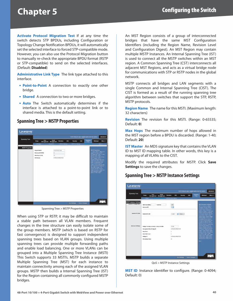
Chapter � Configuring the Switch
4048-Port 10/100 + 4-Port G�gab�t Sw�tch w�th WebV�ew and Power over Ethernet
Act�vate Protocol M�grat�on Test If at any time the switch detects STP BPDUs, including Configuration or Topology Change Notification BPDUs, it will automatically set the selected interface to forced STP-compatible mode . However, you can also use the Protocol Migration button to manually re-check the appropriate BPDU format (RSTP or STP-compatible) to send on the selected interfaces . (Default: D�sabled)
Adm�n�strat�ve L�nk Type The link type attached to this interface .
Po�nt-to-Po�nt A connection to exactly one other bridge .
Shared A connection to two or more bridges .
Auto The Switch automatically determines if the interface is attached to a point-to-point link or to shared media . This is the default setting .
Spanning Tree > MSTP Properties
Spanning Tree > MSTP Properties
When using STP or RSTP, it may be difficult to maintain a stable path between all VLAN members . Frequent changes in the tree structure can easily isolate some of the group members . MSTP (which is based on RSTP for fast convergence) is designed to support independent spanning trees based on VLAN groups . Using multiple spanning trees can provide multiple forwarding paths and enable load balancing . One or more VLANs can be grouped into a Multiple Spanning Tree Instance (MSTI) This Switch supports 33 MSTI’s . MSTP builds a separate Multiple Spanning Tree (MST) for each instance to maintain connectivity among each of the assigned VLAN groups . MSTP then builds a Internal Spanning Tree (IST) for the Region containing all commonly configured MSTP bridges .
•
•
•
An MST Region consists of a group of interconnected bridges that have the same MST Configuration Identifiers (including the Region Name, Revision Level and Configuration Digest) . An MST Region may contain multiple MSTP Instances . An Internal Spanning Tree (IST) is used to connect all the MSTP switches within an MST region . A Common Spanning Tree (CST) interconnects all adjacent MST Regions, and acts as a virtual bridge node for communications with STP or RSTP nodes in the global network .
MSTP connects all bridges and LAN segments with a single Common and Internal Spanning Tree (CIST) . The CIST is formed as a result of the running spanning tree algorithm between switches that support the STP, RSTP, MSTP protocols .
Reg�on Name The name for this MSTI . (Maximum length: 32 characters)
Rev�s�on The revision for this MSTI . (Range: 0-65535; Default: 0)
Max Hops The maximum number of hops allowed in the MST region before a BPDU is discarded . (Range: 1-40; Default: �0)
IST Master An MD5 signature key that contains the VLAN ID to MST ID mapping table . In other words, this key is a mapping of all VLANs to the CIST .
Modify the required attributes for MSTP . Click Save Sett�ngs to save the changes .
Spanning Tree > MSTP Instance Settings
QoS > MSTP Instance Settings
MST ID Instance identifier to configure . (Range: 0-4094; Default: 0)
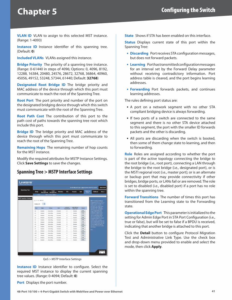
Chapter � Configuring the Switch
4148-Port 10/100 + 4-Port G�gab�t Sw�tch w�th WebV�ew and Power over Ethernet
VLAN ID VLAN to assign to this selected MST instance . (Range: 1-4093)
Instance ID Instance identifier of this spanning tree . (Default: 0)
Included VLANs VLANs assigned this instance .
Br�dge Pr�or�ty The priority of a spanning tree instance . (Range: 0-61440 in steps of 4096; Options: 0, 4096, 8192, 12288, 16384, 20480, 24576, 28672, 32768, 36864, 40960, 45056, 49152, 53248, 57344, 61440; Default: ����8)
Des�gnated Root Br�dge ID The bridge priority and MAC address of the device through which this port must communicate to reach the root of the Spanning Tree .
Root Port The port priority and number of the port on the designated bridging device through which this switch must communicate with the root of the Spanning Tree .
Root Path Cost The contribution of this port to the path cost of paths towards the spanning tree root which include this port .
Br�dge ID The bridge priority and MAC address of the device through which this port must communicate to reach the root of the Spanning Tree .
Rema�n�ng Hops The remaining number of hop counts for the MST instance .
Modify the required attributes for MSTP Instance Settings . Click Save Sett�ngs to save the changes .
Spanning Tree > MSTP Interface Settings
QoS > MSTP Interface Settings
Instance ID Instance identifier to configure . Select the required MST instance to display the current spanning tree values . (Range: 0-4094; Default: 0)
Port Displays the port number .
State Shows if STA has been enabled on this interface .
Status Displays current state of this port within the Spanning Tree:
D�scard�ng Port receives STA configuration messages, but does not forward packets .
Learn�ng Port has transmitted configuration messages for an interval set by the Forward Delay parameter without receiving contradictory information . Port address table is cleared, and the port begins learning addresses .
Forward�ng Port forwards packets, and continues learning addresses .
The rules defining port status are:
A port on a network segment with no other STA compliant bridging device is always forwarding .
If two ports of a switch are connected to the same segment and there is no other STA device attached to this segment, the port with the smaller ID forwards packets and the other is discarding .
All ports are discarding when the switch is booted, then some of them change state to learning, and then to forwarding .
Role Roles are assigned according to whether the port is part of the active topology connecting the bridge to the root bridge (i .e ., root port), connecting a LAN through the bridge to the root bridge (i .e ., designated port), or is the MSTI regional root (i .e ., master port); or is an alternate or backup port that may provide connectivity if other bridges, bridge ports, or LANs fail or are removed . The role is set to disabled (i .e ., disabled port) if a port has no role within the spanning tree .
Forward Trans�t�ons The number of times this port has transitioned from the Learning state to the Forwarding state .
Operat�onal Edge Port This parameter is initialized to the setting for Admin Edge Port in STA Port Configuration (i .e ., true or false), but will be set to false if a BPDU is received, indicating that another bridge is attached to this port .
Click the Deta�l button to configure Protocol Migration Test and Administrative Link Type . Use the check box and drop-down menu provided to enable and select the mode, then click Apply .
•
•
•
•
•
•
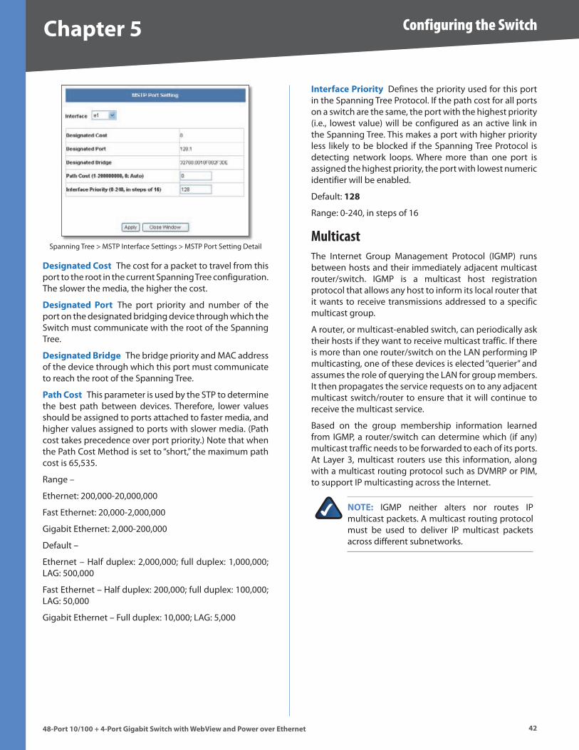
Chapter � Configuring the Switch
4�48-Port 10/100 + 4-Port G�gab�t Sw�tch w�th WebV�ew and Power over Ethernet
Spanning Tree > MSTP Interface Settings > MSTP Port Setting Detail
Des�gnated Cost The cost for a packet to travel from this port to the root in the current Spanning Tree configuration . The slower the media, the higher the cost .
Des�gnated Port The port priority and number of the port on the designated bridging device through which the Switch must communicate with the root of the Spanning Tree .
Des�gnated Br�dge The bridge priority and MAC address of the device through which this port must communicate to reach the root of the Spanning Tree .
Path Cost This parameter is used by the STP to determine the best path between devices . Therefore, lower values should be assigned to ports attached to faster media, and higher values assigned to ports with slower media . (Path cost takes precedence over port priority .) Note that when the Path Cost Method is set to “short,” the maximum path cost is 65,535 .
Range –
Ethernet: 200,000-20,000,000
Fast Ethernet: 20,000-2,000,000
Gigabit Ethernet: 2,000-200,000
Default –
Ethernet – Half duplex: 2,000,000; full duplex: 1,000,000; LAG: 500,000
Fast Ethernet – Half duplex: 200,000; full duplex: 100,000; LAG: 50,000
Gigabit Ethernet – Full duplex: 10,000; LAG: 5,000
Interface Pr�or�ty Defines the priority used for this port in the Spanning Tree Protocol . If the path cost for all ports on a switch are the same, the port with the highest priority (i .e ., lowest value) will be configured as an active link in the Spanning Tree . This makes a port with higher priority less likely to be blocked if the Spanning Tree Protocol is detecting network loops . Where more than one port is assigned the highest priority, the port with lowest numeric identifier will be enabled .
Default: 1�8
Range: 0-240, in steps of 16
MulticastThe Internet Group Management Protocol (IGMP) runs between hosts and their immediately adjacent multicast router/switch . IGMP is a multicast host registration protocol that allows any host to inform its local router that it wants to receive transmissions addressed to a specific multicast group .
A router, or multicast-enabled switch, can periodically ask their hosts if they want to receive multicast traffic . If there is more than one router/switch on the LAN performing IP multicasting, one of these devices is elected “querier” and assumes the role of querying the LAN for group members . It then propagates the service requests on to any adjacent multicast switch/router to ensure that it will continue to receive the multicast service .
Based on the group membership information learned from IGMP, a router/switch can determine which (if any) multicast traffic needs to be forwarded to each of its ports . At Layer 3, multicast routers use this information, along with a multicast routing protocol such as DVMRP or PIM, to support IP multicasting across the Internet .
NOTE: IGMP neither alters nor routes IP multicast packets . A multicast routing protocol must be used to deliver IP multicast packets across different subnetworks .
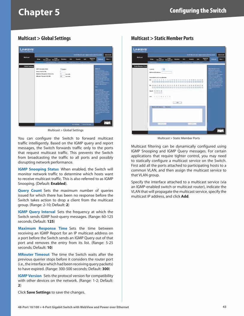
Chapter � Configuring the Switch
4�48-Port 10/100 + 4-Port G�gab�t Sw�tch w�th WebV�ew and Power over Ethernet
Multicast > Global Settings
Multicast > Global Settings
You can configure the Switch to forward multicast traffic intelligently . Based on the IGMP query and report messages, the Switch forwards traffic only to the ports that request multicast traffic . This prevents the Switch from broadcasting the traffic to all ports and possibly disrupting network performance .
IGMP Snoop�ng Status When enabled, the Switch will monitor network traffic to determine which hosts want to receive multicast traffic . This is also referred to as IGMP Snooping . (Default: Enabled) .
Query Count Sets the maximum number of queries issued for which there has been no response before the Switch takes action to drop a client from the multicast group . (Range: 2-10; Default: �)
IGMP Query Interval Sets the frequency at which the Switch sends IGMP host-query messages . (Range: 60-125 seconds; Default: 1��)
Max�mum Response T�me Sets the time between receiving an IGMP Report for an IP multicast address on a port before the Switch sends an IGMP Query out of that port and removes the entry from its list . (Range: 5-25 seconds; Default: 10)
MRouter T�meout The time the Switch waits after the previous querier stops before it considers the router port (i .e ., the interface which had been receiving query packets) to have expired . (Range: 300-500 seconds; Default: �00)
IGMP Vers�on Sets the protocol version for compatibility with other devices on the network . (Range: 1-2; Default: �)
Click Save Sett�ngs to save the changes .
Multicast > Static Member Ports
Multicast > Static Member Ports
Multicast filtering can be dynamically configured using IGMP Snooping and IGMP Query messages . For certain applications that require tighter control, you may need to statically configure a multicast service on the Switch . First add all the ports attached to participating hosts to a common VLAN, and then assign the multicast service to that VLAN group .
Specify the interface attached to a multicast service (via an IGMP-enabled switch or multicast router), indicate the VLAN that will propagate the multicast service, specify the multicast IP address, and click Add .
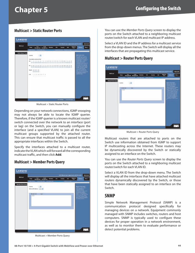
Chapter � Configuring the Switch
4448-Port 10/100 + 4-Port G�gab�t Sw�tch w�th WebV�ew and Power over Ethernet
Multicast > Static Router Ports
Multicast > Static Router Ports
Depending on your network connections, IGMP snooping may not always be able to locate the IGMP querier . Therefore, if the IGMP querier is a known multicast router/ switch connected over the network to an interface (port or lag) on the Switch, you can manually configure the interface (and a specified VLAN) to join all the current multicast groups supported by the attached router . This can ensure that multicast traffic is passed to all the appropriate interfaces within the Switch .
Specify the interfaces attached to a multicast router, indicate the VLAN which will forward all the corresponding multicast traffic, and then click Add .
Multicast > Member Ports Query
Multicast > Member Ports Query
You can use the Member Ports Query screen to display the ports on the Switch attached to a neighboring multicast router/switch for each VLAN and multicast IP address .
Select a VLAN ID and the IP address for a multicast service from the drop-down menus . The Switch will display all the interfaces that are propagating this multicast service .
Multicast > Router Ports Query
Multicast > Router Ports Query
Multicast routers that are attached to ports on the Switch use information obtained from IGMP to support IP multicasting across the Internet . These routers may be dynamically discovered by the Switch or statically assigned to an interface on the Switch .
You can use the Router Ports Query screen to display the ports on the Switch attached to a neighboring multicast router/switch for each VLAN ID .
Select a VLAN ID from the drop-down menu . The Switch will display all the interfaces that have attached multicast routers dynamically discovered by the Switch, or those that have been statically assigned to an interface on the Switch .
SNMPSimple Network Management Protocol (SNMP) is a communication protocol designed specifically for managing devices on a network . Equipment commonly managed with SNMP includes switches, routers and host computers . SNMP is typically used to configure these devices for proper operation in a network environment, as well as to monitor them to evaluate performance or detect potential problems .
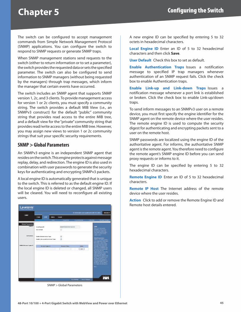
Chapter � Configuring the Switch
4�48-Port 10/100 + 4-Port G�gab�t Sw�tch w�th WebV�ew and Power over Ethernet
The switch can be configured to accept management commands from Simple Network Management Protocol (SNMP) applications . You can configure the switch to respond to SNMP requests or generate SNMP traps .
When SNMP management stations send requests to the switch (either to return information or to set a parameter), the switch provides the requested data or sets the specified parameter . The switch can also be configured to send information to SNMP managers (without being requested by the managers) through trap messages, which inform the manager that certain events have occurred .
The switch includes an SNMP agent that supports SNMP version 1, 2c, and 3 clients . To provide management access for version 1 or 2c clients, you must specify a community string . The switch provides a default MIB View (i .e ., an SNMPv3 construct) for the default “public” community string that provides read access to the entire MIB tree, and a default view for the “private” community string that provides read/write access to the entire MIB tree . However, you may assign new views to version 1 or 2c community strings that suit your specific security requirements .
SNMP > Global ParametersAn SNMPv3 engine is an independent SNMP agent that resides on the switch . This engine protects against message replay, delay, and redirection . The engine ID is also used in combination with user passwords to generate the security keys for authenticating and encrypting SNMPv3 packets .
A local engine ID is automatically generated that is unique to the switch . This is referred to as the default engine ID . If the local engine ID is deleted or changed, all SNMP users will be cleared . You will need to reconfigure all existing users .
SNMP > Global Parameters
A new engine ID can be specified by entering 5 to 32 octets in hexadecimal characters .
Local Eng�ne ID Enter an ID of 5 to 32 hexadecimal characters and then click Save .
User Default Check this box to set as default .
Enable Authent�cat�on Traps Issues a notification message to specified IP trap managers whenever authentication of an SNMP request fails . Click the check box to enable Authentication traps .
Enable L�nk-up and L�nk-down Traps Issues a notification message whenever a port link is established or broken . Click the check box to enable Link-up/down traps .
To send inform messages to an SNMPv3 user on a remote device, you must first specify the engine identifier for the SNMP agent on the remote device where the user resides . The remote engine ID is used to compute the security digest for authenticating and encrypting packets sent to a user on the remote host .
SNMP passwords are localized using the engine ID of the authoritative agent . For informs, the authoritative SNMP agent is the remote agent . You therefore need to configure the remote agent’s SNMP engine ID before you can send proxy requests or informs to it .
The engine ID can be specified by entering 5 to 32 hexadecimal characters .
Remote Eng�ne ID Enter an ID of 5 to 32 hexadecimal characters .
Remote IP Host The Internet address of the remote device where the user resides .
Act�on Click to add or remove the Remote Engine ID and Remote host details entered .
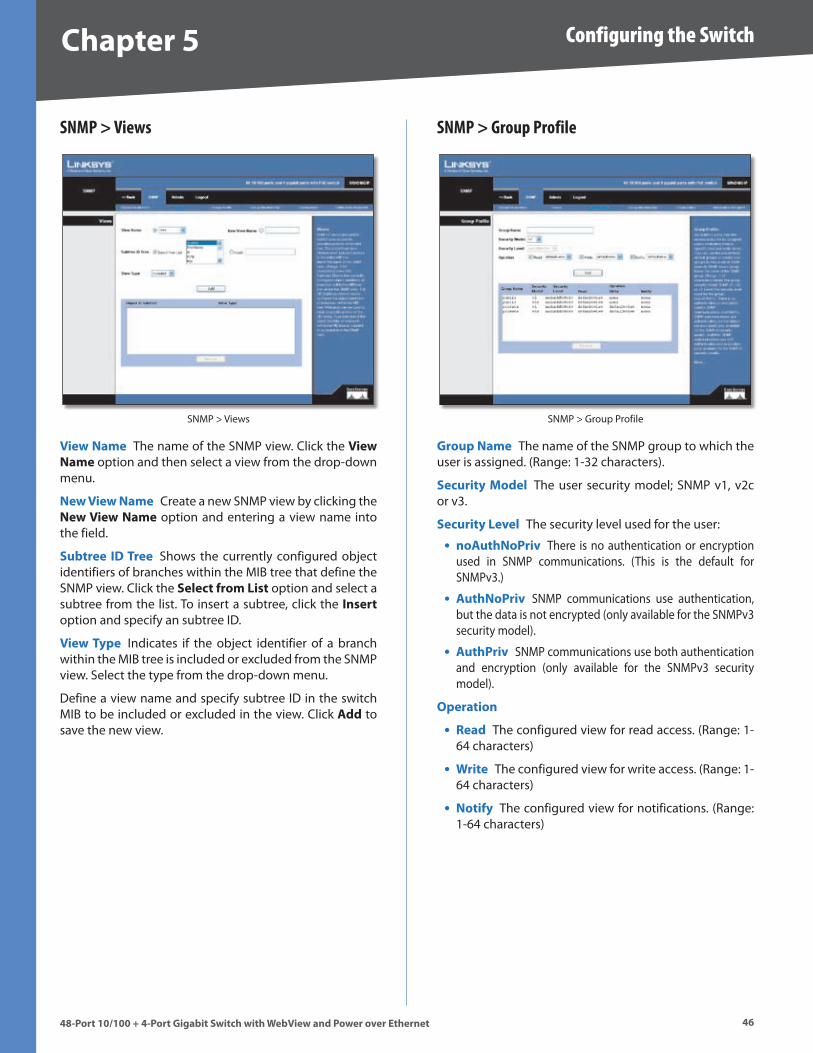
Chapter � Configuring the Switch
4�48-Port 10/100 + 4-Port G�gab�t Sw�tch w�th WebV�ew and Power over Ethernet
SNMP > Views
SNMP > Views
V�ew Name The name of the SNMP view . Click the V�ew Name option and then select a view from the drop-down menu .
New V�ew Name Create a new SNMP view by clicking the New V�ew Name option and entering a view name into the field .
Subtree ID Tree Shows the currently configured object identifiers of branches within the MIB tree that define the SNMP view . Click the Select from L�st option and select a subtree from the list . To insert a subtree, click the Insert option and specify an subtree ID .
V�ew Type Indicates if the object identifier of a branch within the MIB tree is included or excluded from the SNMP view . Select the type from the drop-down menu .
Define a view name and specify subtree ID in the switch MIB to be included or excluded in the view . Click Add to save the new view .
SNMP > Group Profile
SNMP > Group Profile
Group Name The name of the SNMP group to which the user is assigned . (Range: 1-32 characters) .
Secur�ty Model The user security model; SNMP v1, v2c or v3 .
Secur�ty Level The security level used for the user:
noAuthNoPr�v There is no authentication or encryption used in SNMP communications . (This is the default for SNMPv3 .)
AuthNoPr�v SNMP communications use authentication, but the data is not encrypted (only available for the SNMPv3 security model) .
AuthPr�v SNMP communications use both authentication and encryption (only available for the SNMPv3 security model) .
Operat�on
Read The configured view for read access . (Range: 1-64 characters)
Wr�te The configured view for write access . (Range: 1-64 characters)
Not�fy The configured view for notifications . (Range: 1-64 characters)
•
•
•
•
•
•
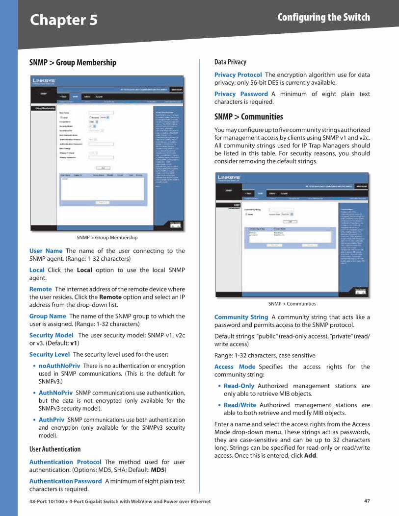
Chapter � Configuring the Switch
4�48-Port 10/100 + 4-Port G�gab�t Sw�tch w�th WebV�ew and Power over Ethernet
SNMP > Group Membership
SNMP > Group Membership
User Name The name of the user connecting to the SNMP agent . (Range: 1-32 characters)
Local Click the Local option to use the local SNMP agent .
Remote The Internet address of the remote device where the user resides . Click the Remote option and select an IP address from the drop-down list .
Group Name The name of the SNMP group to which the user is assigned . (Range: 1-32 characters)
Secur�ty Model The user security model; SNMP v1, v2c or v3 . (Default: v1)
Secur�ty Level The security level used for the user:
noAuthNoPr�v There is no authentication or encryption used in SNMP communications . (This is the default for SNMPv3 .)
AuthNoPr�v SNMP communications use authentication, but the data is not encrypted (only available for the SNMPv3 security model) .
AuthPr�v SNMP communications use both authentication and encryption (only available for the SNMPv3 security model) .
User Authentication
Authent�cat�on Protocol The method used for user authentication . (Options: MD5, SHA; Default: MD�)
Authent�cat�on Password A minimum of eight plain text characters is required .
•
•
•
Data Privacy
Pr�vacy Protocol The encryption algorithm use for data privacy; only 56-bit DES is currently available .
Pr�vacy Password A minimum of eight plain text characters is required .
SNMP > CommunitiesYou may configure up to five community strings authorized for management access by clients using SNMP v1 and v2c . All community strings used for IP Trap Managers should be listed in this table . For security reasons, you should consider removing the default strings .
SNMP > Communities
Commun�ty Str�ng A community string that acts like a password and permits access to the SNMP protocol .
Default strings: “public” (read-only access), “private” (read/write access)
Range: 1-32 characters, case sensitive
Access Mode Specifies the access rights for the community string:
Read-Only Authorized management stations are only able to retrieve MIB objects .
Read/Wr�te Authorized management stations are able to both retrieve and modify MIB objects .
Enter a name and select the access rights from the Access Mode drop-down menu . These strings act as passwords, they are case-sensitive and can be up to 32 characters long . Strings can be specified for read-only or read/write access . Once this is entered, click Add .
•
•
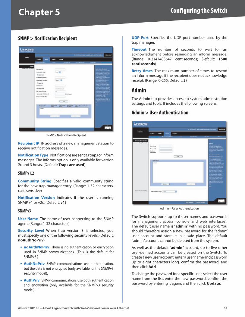
Chapter � Configuring the Switch
4848-Port 10/100 + 4-Port G�gab�t Sw�tch w�th WebV�ew and Power over Ethernet
SNMP > Notification Recipient
SNMP > Notification Recipient
Rec�p�ent IP IP address of a new management station to receive notification messages .
Not�f�cat�on Type Notifications are sent as traps or inform messages . The informs option is only available for version 2c and 3 hosts . (Default: Traps are used)
SNMPv1,2
Commun�ty Str�ng Specifies a valid community string for the new trap manager entry . (Range: 1-32 characters, case sensitive)
Not�f�cat�on Vers�on Indicates if the user is running SNMP v1 or v2c . (Default: v1)
SNMPv3
User Name The name of user connecting to the SNMP agent . (Range: 1-32 characters)
Secur�ty Level When trap version 3 is selected, you must specify one of the following security levels . (Default: noAuthNoPr�v)
noAuthNoPr�v There is no authentication or encryption used in SNMP communications . (This is the default for SNMPv3 .)
AuthNoPr�v SNMP communications use authentication, but the data is not encrypted (only available for the SNMPv3 security model) .
AuthPr�v SNMP communications use both authentication and encryption (only available for the SNMPv3 security model) .
•
•
•
UDP Port Specifies the UDP port number used by the trap manager .
T�meout The number of seconds to wait for an acknowledgment before resending an inform message . (Range: 0-2147483647 centiseconds; Default: 1�00 cent�seconds)
Retry t�mes The maximum number of times to resend an inform message if the recipient does not acknowledge receipt . (Range: 0-255; Default: �)
AdminThe Admin tab provides access to system administration settings and tools . It includes the following screens:
Admin > User Authentication
Admin > User Authentication
The Switch supports up to 6 user names and passwords for management access (console and web interfaces) . The default user name is “adm�n” with no password . You should therefore assign a new password for the “admin” user account and store it in a safe place . The default “admin” account cannot be deleted from the system .
As well as the default “adm�n” account, up to five other user-defined accounts can be created on the Switch . To create a new user account, enter a user name and password up to eight characters long, confirm the password, and then click Add .
To change the password for a specific user, select the user name from the list, enter the new password, confirm the password by entering it again, and then click Update .
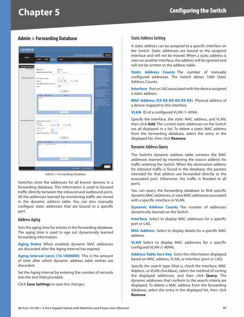
Chapter � Configuring the Switch
4�48-Port 10/100 + 4-Port G�gab�t Sw�tch w�th WebV�ew and Power over Ethernet
Admin > Forwarding Database
Admin > Forwarding Database
Switches store the addresses for all known devices in a forwarding database . This information is used to forward traffic directly between the inbound and outbound ports . All the addresses learned by monitoring traffic are stored in the dynamic address table . You can also manually configure static addresses that are bound to a specific port .
Address Aging
Sets the aging time for entries in the forwarding database . The aging time is used to age out dynamically learned forwarding information .
Ag�ng Status When enabled, dynamic MAC addresses are discarded after the Aging Interval has expired .
Ag�ng Interval (secs) (10-1000000) This is the amount of time after which dynamic address table entries are discarded .
Set the Aging Interval by entering the number of seconds into the text field provided .
Click Save Sett�ngs to save the changes .
Static Address Setting
A static address can be assigned to a specific interface on the Switch . Static addresses are bound to the assigned interface and will not be moved . When a static address is seen on another interface, the address will be ignored and will not be written to the address table .
Stat�c Address Counts The number of manually configured addresses . The Switch allows 1000 Static Address Counts .
Interface Port or LAG associated with the device assigned a static address .
MAC Address (XX-XX-XX-XX-XX-XX) Physical address of a device mapped to this interface .
VLAN ID of a configured VLAN (1-4094) .
Specify the interface, the static MAC address, and VLAN, then click Add . The current static addresses on the Switch are all displayed in a list . To delete a static MAC address from the forwarding database, select the entry in the displayed list, then click Remove .
Dynamic Address Query
The Switch’s dynamic address table contains the MAC addresses learned by monitoring the source address for traffic entering the Switch . When the destination address for inbound traffic is found in the database, the packets intended for that address are forwarded directly to the associated port . Otherwise, the traffic is flooded to all ports .
You can query the forwarding database to find specific dynamic MAC addresses, or view MAC addresses associated with a specific interface or VLAN .
Dynam�c Address Counts The number of addresses dynamically learned on the Switch .
Interface Select to display MAC addresses for a specific port or LAG .
MAC Address Select to display details for a specific MAC address .
VLAN Select to display MAC addresses for a specific configured VLAN (1-4094) .
Address Table Sort Key Sorts the information displayed based on MAC address, VLAN, or interface (port or LAG) .
Specify the search type (that is, check the Interface, MAC Address, or VLAN checkbox), select the method of sorting the displayed addresses, and then click Query . The dynamic addresses that conform to the search criteria are displayed . To delete a MAC address from the forwarding database, select the entry in the displayed list, then click Remove .
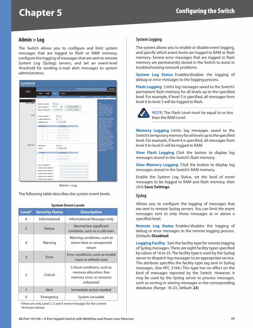
Chapter � Configuring the Switch
�048-Port 10/100 + 4-Port G�gab�t Sw�tch w�th WebV�ew and Power over Ethernet
Admin > LogThe Switch allows you to configure and limit system messages that are logged to flash or RAM memory, configure the logging of messages that are sent to remote System Log (Syslog) servers, and set an event-level threshold for sending e-mail alert messages to system administrators .
Admin > Log
The following table describes the system event levels .
System Event Levels
Level† Sever�ty Name Descr�pt�on
6 Informational Informational Messages only
5 NoticeNormal but significant
condition, such as a cold start
4 WarningWarning conditions, such as return false or unexpected
return
3 ErrorError conditions, such as invalid
input or default used
2 Critical
Critical conditions, such as memory allocation, free
memory error, or resource exhausted
1 Alert Immediate action needed
0 Emergency System unusable
There are only Level 2, 5 and 6 event messages for the current firmware release .
†
System Logging
The system allows you to enable or disable event logging, and specify which event levels are logged to RAM or flash memory . Severe error messages that are logged to flash memory are permanently stored in the Switch to assist in troubleshooting network problems .
System Log Status Enables/disables the logging of debug or error messages to the logging process .
Flash Logg�ng Limits log messages saved to the Switch’s permanent flash memory for all levels up to the specified level . For example, if level 3 is specified, all messages from level 0 to level 3 will be logged to flash .
NOTE: The Flash Level must be equal to or less than the RAM Level .
Memory Logg�ng Limits log messages saved to the Switch’s temporary memory for all levels up to the specified level . For example, if level 6 is specified, all messages from level 0 to level 6 will be logged to RAM .
V�ew Flash Logg�ng Click the button to display log messages stored in the Switch’s flash memory .
V�ew Memory Logg�ng Click the button to display log messages stored in the Switch’s RAM memory .
Enable the System Log Status, set the level of event messages to be logged to RAM and flash memory, then click Save Sett�ngs .
Syslog
Allows you to configure the logging of messages that are sent to remote Syslog servers . You can limit the event messages sent to only those messages at or above a specified level .
Remote Log Status Enables/disables the logging of debug or error messages to the remote logging process . (Default: D�sabled)
Logg�ng Fac�l�ty Sets the facility type for remote logging of Syslog messages . There are eight facility types specified by values of 16 to 23 . The facility type is used by the Syslog server to dispatch log messages to an appropriate service . The attribute specifies the facility type tag sent in Syslog messages . (See RFC 3164 .) This type has no effect on the kind of messages reported by the Switch . However, it may be used by the Syslog server to process messages, such as sorting or storing messages in the corresponding database . (Range: 16-23, Default: ��)
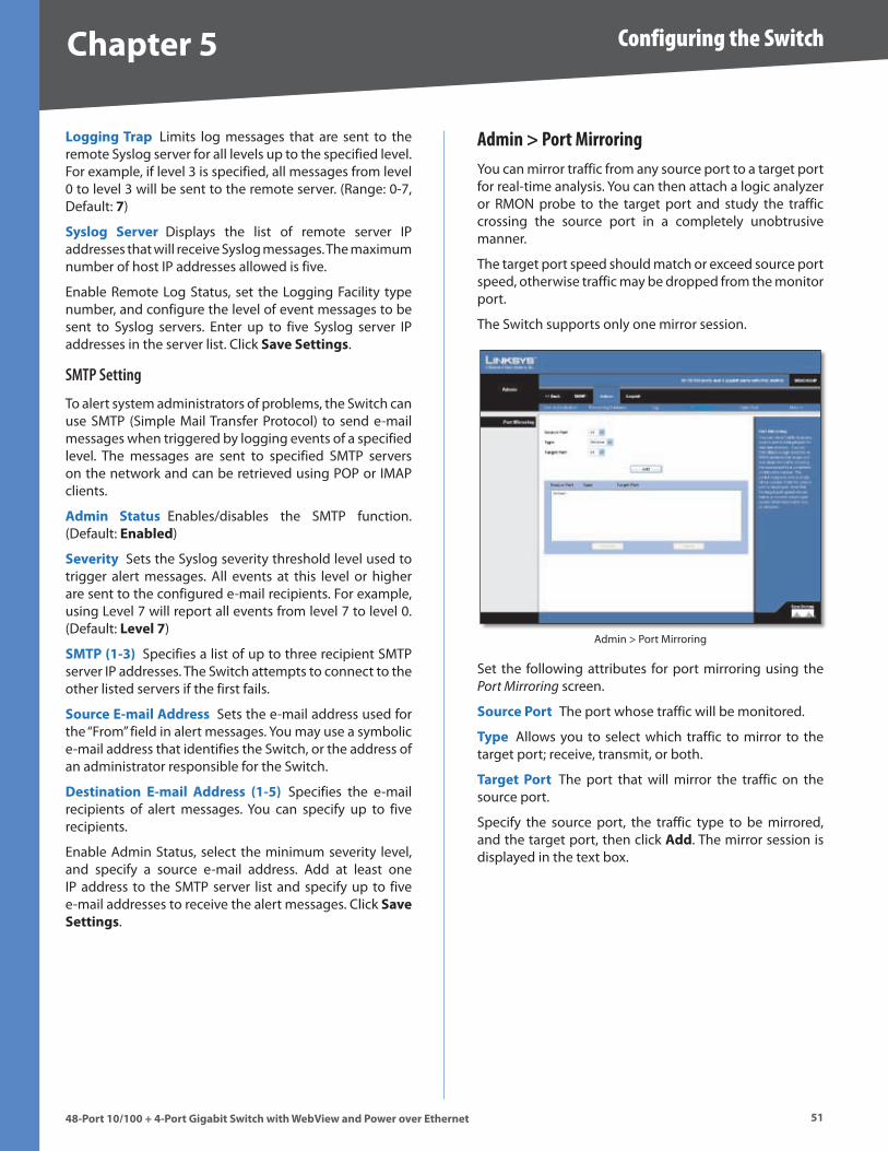
Chapter � Configuring the Switch
�148-Port 10/100 + 4-Port G�gab�t Sw�tch w�th WebV�ew and Power over Ethernet
Logg�ng Trap Limits log messages that are sent to the remote Syslog server for all levels up to the specified level . For example, if level 3 is specified, all messages from level 0 to level 3 will be sent to the remote server . (Range: 0-7, Default: �)
Syslog Server Displays the list of remote server IP addresses that will receive Syslog messages . The maximum number of host IP addresses allowed is five .
Enable Remote Log Status, set the Logging Facility type number, and configure the level of event messages to be sent to Syslog servers . Enter up to five Syslog server IP addresses in the server list . Click Save Sett�ngs .
SMTP Setting
To alert system administrators of problems, the Switch can use SMTP (Simple Mail Transfer Protocol) to send e-mail messages when triggered by logging events of a specified level . The messages are sent to specified SMTP servers on the network and can be retrieved using POP or IMAP clients .
Adm�n Status Enables/disables the SMTP function . (Default: Enabled)
Sever�ty Sets the Syslog severity threshold level used to trigger alert messages . All events at this level or higher are sent to the configured e-mail recipients . For example, using Level 7 will report all events from level 7 to level 0 . (Default: Level �)
SMTP (1-�) Specifies a list of up to three recipient SMTP server IP addresses . The Switch attempts to connect to the other listed servers if the first fails .
Source E-ma�l Address Sets the e-mail address used for the “From” field in alert messages . You may use a symbolic e-mail address that identifies the Switch, or the address of an administrator responsible for the Switch .
Dest�nat�on E-ma�l Address (1-�) Specifies the e-mail recipients of alert messages . You can specify up to five recipients .
Enable Admin Status, select the minimum severity level, and specify a source e-mail address . Add at least one IP address to the SMTP server list and specify up to five e-mail addresses to receive the alert messages . Click Save Sett�ngs .
Admin > Port MirroringYou can mirror traffic from any source port to a target port for real-time analysis . You can then attach a logic analyzer or RMON probe to the target port and study the traffic crossing the source port in a completely unobtrusive manner .
The target port speed should match or exceed source port speed, otherwise traffic may be dropped from the monitor port .
The Switch supports only one mirror session .
Admin > Port Mirroring
Set the following attributes for port mirroring using the Port Mirroring screen .
Source Port The port whose traffic will be monitored .
Type Allows you to select which traffic to mirror to the target port; receive, transmit, or both .
Target Port The port that will mirror the traffic on the source port .
Specify the source port, the traffic type to be mirrored, and the target port, then click Add . The mirror session is displayed in the text box .
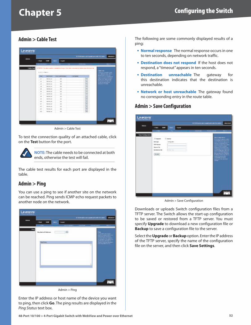
Chapter � Configuring the Switch
��48-Port 10/100 + 4-Port G�gab�t Sw�tch w�th WebV�ew and Power over Ethernet
Admin > Cable Test
Admin > Cable Test
To test the connection quality of an attached cable, click on the Test button for the port .
NOTE: The cable needs to be connected at both ends, otherwise the test will fail .
The cable test results for each port are displayed in the table .
Admin > PingYou can use a ping to see if another site on the network can be reached . Ping sends ICMP echo request packets to another node on the network .
Admin > Ping
Enter the IP address or host name of the device you want to ping, then click Go . The ping results are displayed in the Ping Status text box .
The following are some commonly displayed results of a ping:
Normal response The normal response occurs in one to ten seconds, depending on network traffic .
Dest�nat�on does not respond If the host does not respond, a “timeout” appears in ten seconds .
Dest�nat�on unreachable The gateway for this destination indicates that the destination is unreachable .
Network or host unreachable The gateway found no corresponding entry in the route table .
Admin > Save Configuration
Admin > Save Configuration
Downloads or uploads Switch configuration files from a TFTP server . The Switch allows the start-up configuration to be saved or restored from a TFTP server . You must specify Upgrade to download a new configuration file or Backup to save a configuration file to the server .
Select the Upgrade or Backup option . Enter the IP address of the TFTP server, specify the name of the configuration file on the server, and then click Save Sett�ngs .
•
•
•
•
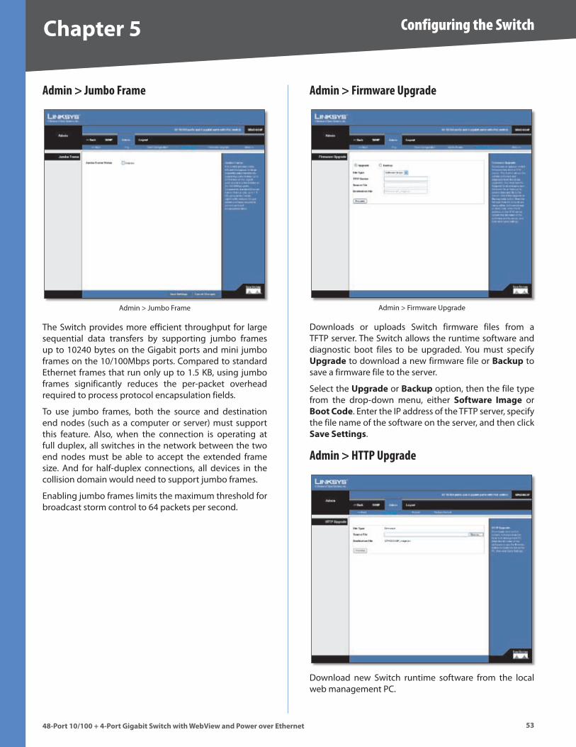
Chapter � Configuring the Switch
��48-Port 10/100 + 4-Port G�gab�t Sw�tch w�th WebV�ew and Power over Ethernet
Admin > Jumbo Frame
Admin > Jumbo Frame
The Switch provides more efficient throughput for large sequential data transfers by supporting jumbo frames up to 10240 bytes on the Gigabit ports and mini jumbo frames on the 10/100Mbps ports . Compared to standard Ethernet frames that run only up to 1 .5 KB, using jumbo frames significantly reduces the per-packet overhead required to process protocol encapsulation fields .
To use jumbo frames, both the source and destination end nodes (such as a computer or server) must support this feature . Also, when the connection is operating at full duplex, all switches in the network between the two end nodes must be able to accept the extended frame size . And for half-duplex connections, all devices in the collision domain would need to support jumbo frames .
Enabling jumbo frames limits the maximum threshold for broadcast storm control to 64 packets per second .
Admin > Firmware Upgrade
Admin > Firmware Upgrade
Downloads or uploads Switch firmware files from a TFTP server . The Switch allows the runtime software and diagnostic boot files to be upgraded . You must specify Upgrade to download a new firmware file or Backup to save a firmware file to the server .
Select the Upgrade or Backup option, then the file type from the drop-down menu, either Software Image or Boot Code . Enter the IP address of the TFTP server, specify the file name of the software on the server, and then click Save Sett�ngs .
Admin > HTTP Upgrade
Download new Switch runtime software from the local web management PC .
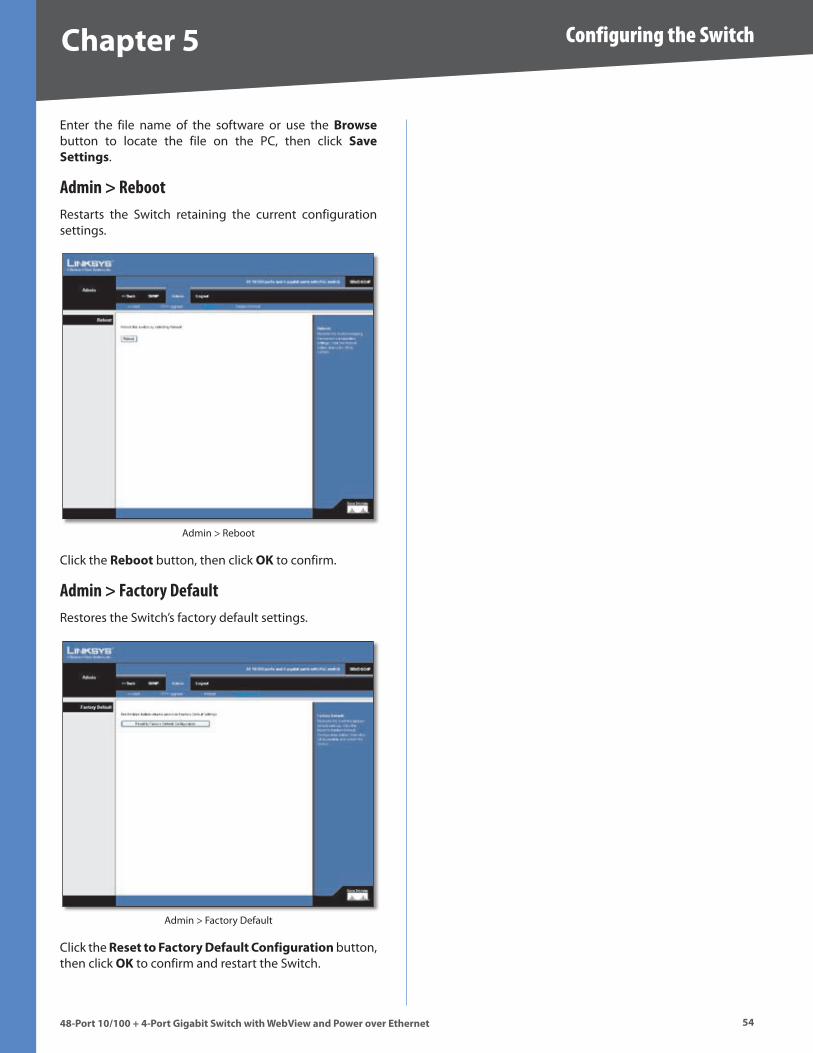
Chapter � Configuring the Switch
�448-Port 10/100 + 4-Port G�gab�t Sw�tch w�th WebV�ew and Power over Ethernet
Enter the file name of the software or use the Browse button to locate the file on the PC, then click Save Sett�ngs .
Admin > RebootRestarts the Switch retaining the current configuration settings .
Admin > Reboot
Click the Reboot button, then click OK to confirm .
Admin > Factory DefaultRestores the Switch’s factory default settings .
Admin > Factory Default
Click the Reset to Factory Default Conf�gurat�on button, then click OK to confirm and restart the Switch .
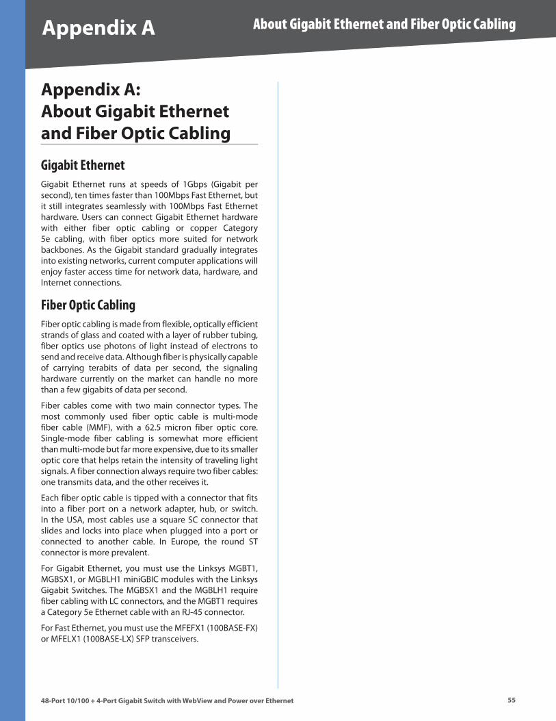
��
About Gigabit Ethernet and Fiber Optic Cabling
48-Port 10/100 + 4-Port G�gab�t Sw�tch w�th WebV�ew and Power over Ethernet
Append�x A
Append�x A: About G�gab�t Ethernet and F�ber Opt�c Cabl�ng
Gigabit EthernetGigabit Ethernet runs at speeds of 1Gbps (Gigabit per second), ten times faster than 100Mbps Fast Ethernet, but it still integrates seamlessly with 100Mbps Fast Ethernet hardware . Users can connect Gigabit Ethernet hardware with either fiber optic cabling or copper Category 5e cabling, with fiber optics more suited for network backbones . As the Gigabit standard gradually integrates into existing networks, current computer applications will enjoy faster access time for network data, hardware, and Internet connections .
Fiber Optic CablingFiber optic cabling is made from flexible, optically efficient strands of glass and coated with a layer of rubber tubing, fiber optics use photons of light instead of electrons to send and receive data . Although fiber is physically capable of carrying terabits of data per second, the signaling hardware currently on the market can handle no more than a few gigabits of data per second .
Fiber cables come with two main connector types . The most commonly used fiber optic cable is multi-mode fiber cable (MMF), with a 62 .5 micron fiber optic core . Single-mode fiber cabling is somewhat more efficient than multi-mode but far more expensive, due to its smaller optic core that helps retain the intensity of traveling light signals . A fiber connection always require two fiber cables: one transmits data, and the other receives it .
Each fiber optic cable is tipped with a connector that fits into a fiber port on a network adapter, hub, or switch . In the USA, most cables use a square SC connector that slides and locks into place when plugged into a port or connected to another cable . In Europe, the round ST connector is more prevalent .
For Gigabit Ethernet, you must use the Linksys MGBT1, MGBSX1, or MGBLH1 miniGBIC modules with the Linksys Gigabit Switches . The MGBSX1 and the MGBLH1 require fiber cabling with LC connectors, and the MGBT1 requires a Category 5e Ethernet cable with an RJ-45 connector .
For Fast Ethernet, you must use the MFEFX1 (100BASE-FX) or MFELX1 (100BASE-LX) SFP transceivers .
��
Glossary
48-Port 10/100 + 4-Port G�gab�t Sw�tch w�th WebV�ew and Power over Ethernet
Append�x B
Append�x B: GlossaryThis glossary contains some basic networking terms you may come across when using this product .
WEB: For additional terms, please visit the glossary at www.l�nksys.com/glossary
Access Mode - Specifies the method by which user access is granted to the system .
Access Po�nt - A device that allows wireless-equipped computers and other devices to communicate with a wired network . Also used to expand the range of a wireless network .
Access Prof�les - Allows network managers to define profiles and rules for accessing the device . Access to management functions can be limited to user groups, which are defined by the following criteria:
Ingress interfaces
Source IP address and/or Source IP subnets .
ACE - Filters in Access Control Lists (ACL) that determine which network traffic is forwarded . An ACE is based on the following criteria:
Protocol
Protocol ID
Source Port
Destination Port
Wildcard Mask
Source IP Address
Destination IP Address
ACL (Access Control L�st) - Access Control Lists are used to grant, deny, or limit access devices, features, or applications .
Auto-negot�at�on - Allows 10/100 Mbps or 10/100/1000 Mbps Ethernet ports to automatically establish the optimal duplex mode, flow control, and speed .
Back Pressure - A mechanism used with Half Duplex mode that enables a port not to receive a message .
Bandw�dth - The transmission capacity of a given device or network .
Bandw�dth Ass�gnments - Indicates the amount of bandwidth assigned to a specific application, user, and/or interface .
•
•
•
•
•
•
•
•
•
Baud - Indicates the number of signaling elements transmitted each second .
Best Effort - Indicates that traffic is assigned to the lowest priority queue, and packet delivery is not guaranteed .
B�t - A binary digit .
Boot - To start a device and cause it to start executing instructions .
Browser - An application program that provides a way to look at and interact with all the information on the World Wide Web .
Br�dge - A device that connect two networks . Bridges are hardware specific, however they are protocol independent . Bridges operate at Layer 1 and Layer 2 levels .
Broadcast Doma�n - Devices sets that receive broadcast frames originating from any device within a designated set . Routers bind Broadcast domains, because routers do not forward broadcast frames .
Broadcast Storm - An excessive amount of broadcast messages simultaneously transmitted across a network by a single port . Forwarded message responses are heaped onto the network, overloading network resources or causing the network to time out .
Burst - A packet transmission at faster than normal rates . Bursts are limited in time and only occur under specific conditions .
Burst S�ze - Indicates the burst size transmitted at a faster than normal rate .
Byte - A unit of data that is usually eight bits long
Cable Modem - A device that connects a computer to the cable television network, which in turn connects to the Internet .
CBS (Comm�tted Burst S�ze) - Indicates the maximum number of data bits transmitted within a specific time interval .
CIR (Comm�tted Informat�on Rate) - The data rate is averaged over a minimum time increment .
Class Maps - An aspect of Quality of Service system that is comprised of an IP ACL and/or a MAC ACL . Class maps are configured to match packet criteria, and are matched to packets in a first-fit fashion .
Combo Ports - A single logical port with two physical connections, including an RJ-45 connection and a SFP connection .
Commun�t�es - Specifies a group of users which retain the same system access rights .
��
Glossary
48-Port 10/100 + 4-Port G�gab�t Sw�tch w�th WebV�ew and Power over Ethernet
Append�x B
CoS (Class of Serv�ce) - The 802 .1p priority scheme . CoS provides a method for tagging packets with priority information . A CoS value between 0-7 is added to the Layer II header of packets, where zero is the lowest priority and seven is the highest .
DDNS (Dynam�c Doma�n Name System) - Allows the hosting of a website, FTP server, or e-mail server with a fixed domain name (e .g ., www .xyz .com) and a dynamic IP address .
Default Gateway - A device that forwards Internet traffic from your local area network .
DHCP (Dynam�c Host Conf�gurat�on Protocol) - A networking protocol that allows administrators to assign temporary IP addresses to network computers by “leasing” an IP address to a user for a limited amount of time, instead of assigning permanent IP addresses .
DHCP Cl�ents - An Internet host using DHCP to obtain configuration parameters, such as a network address .
DHCP Server - An Internet host that returns configuration parameters to DHCP clients .
DNS (Doma�n Name Server) - The IP address of your ISP’s server, which translates the names of websites into IP addresses .
Doma�n - A specific name for a network of computers .
Download - To receive a file transmitted over a network .
DSL (D�g�tal Subscr�ber L�ne) - An always-on broadband connection over traditional phone lines .
DSCP (D�ffServ Code Po�nt) - Provides a method of tagging IP packets with QoS priority information .
Dynam�c IP Address - A temporary IP address assigned by a DHCP server .
EIGRP (Enhanced Inter�or Gateway Rout�ng Protocol) - Provides fast convergence, support for variable-length subnet mask, and supports multiple network layer protocols .
Encrypt�on - Encoding data transmitted in a network .
Ethernet - IEEE standard network protocol that specifies how data is placed on and retrieved from a common transmission medium .
F�rmware - The programming code that runs a networking device .
Flow Control - Enables lower speed devices to communicate with higher speed devices . This is implemented by the higher speed device refraining from sending packets .
FTP (F�le Transfer Protocol) - A protocol used to transfer files over a TCP/IP network .
Full Duplex - The ability of a networking device to receive and transmit data simultaneously .
GARP (General Attr�butes Reg�strat�on Protocol) - Registers client stations into a multicast domain .
Gateway - A device that interconnects networks with different, incompatible communications protocols .
GBIC (G�gaB�t Interface Converter) - A hardware module used to attach network devices to fiber-based transmission systems . GBIC converts the serial electrical signals to serial optical signals and vice versa .
GVRP (GARP VLAN Reg�strat�on Protocol) - Registers client stations into a VLANs .
Half Duplex - Data transmission that can occur in two directions over a single line, but only one direction at a time .
HTTP (HyperText Transport Protocol) - The communications protocol used to connect to servers on the World Wide Web .
HTTPS (HyperText Transport Protocol Secure) - An extension to the standard HTTP protocol that provides confidentiality by encrypting the traffic from the website . By default this protocol uses TCP port 443 .
ICMP (Internet Control Message Protocol) - Allows the gateway or destination host to communicate with the source host . For example, to report a processing error .
IGMP (Internet Group Management Protocol) - Allows hosts to notify their local switch or router that they want to receive transmissions assigned to a specific multicast group .
IP (Internet Protocol) - A protocol used to send data over a network .
IP Address - The address used to identify a computer or device on a network .
IPCONFIG - A Windows 2000 and XP utility that displays the IP address for a particular networking device .
IPSec (Internet Protocol Secur�ty) - A VPN protocol used to implement secure exchange of packets at the IP layer .
ISP (Internet Serv�ce Prov�der) - A company that provides access to the Internet .
Jumbo Frames - Enable transporting identical data in fewer frames . Jumbo Frames reduce overhead, lower processing time, and ensure fewer interrupts .
LAG (L�nk Aggregated Group) - Aggregates ports or VLANs into a single virtual port or VLAN .
LAN - The computers and networking products that make up your local network .
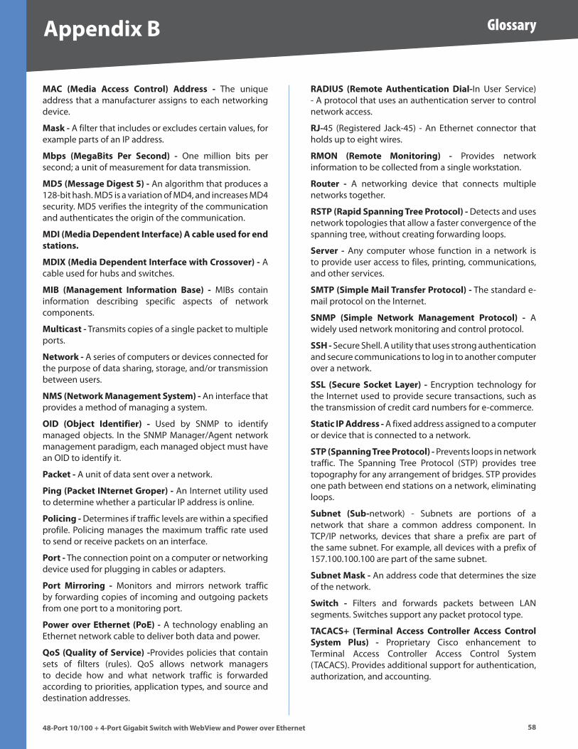
�8
Glossary
48-Port 10/100 + 4-Port G�gab�t Sw�tch w�th WebV�ew and Power over Ethernet
Append�x B
MAC (Med�a Access Control) Address - The unique address that a manufacturer assigns to each networking device .
Mask - A filter that includes or excludes certain values, for example parts of an IP address .
Mbps (MegaB�ts Per Second) - One million bits per second; a unit of measurement for data transmission .
MD� (Message D�gest �) - An algorithm that produces a 128-bit hash . MD5 is a variation of MD4, and increases MD4 security . MD5 verifies the integrity of the communication and authenticates the origin of the communication .
MDI (Med�a Dependent Interface) A cable used for end stat�ons.
MDIX (Med�a Dependent Interface w�th Crossover) - A cable used for hubs and switches .
MIB (Management Informat�on Base) - MIBs contain information describing specific aspects of network components .
Mult�cast - Transmits copies of a single packet to multiple ports .
Network - A series of computers or devices connected for the purpose of data sharing, storage, and/or transmission between users .
NMS (Network Management System) - An interface that provides a method of managing a system .
OID (Object Ident�f�er) - Used by SNMP to identify managed objects . In the SNMP Manager/Agent network management paradigm, each managed object must have an OID to identify it .
Packet - A unit of data sent over a network .
P�ng (Packet INternet Groper) - An Internet utility used to determine whether a particular IP address is online .
Pol�c�ng - Determines if traffic levels are within a specified profile . Policing manages the maximum traffic rate used to send or receive packets on an interface .
Port - The connection point on a computer or networking device used for plugging in cables or adapters .
Port M�rror�ng - Monitors and mirrors network traffic by forwarding copies of incoming and outgoing packets from one port to a monitoring port .
Power over Ethernet (PoE) - A technology enabling an Ethernet network cable to deliver both data and power .
QoS (Qual�ty of Serv�ce) -Provides policies that contain sets of filters (rules) . QoS allows network managers to decide how and what network traffic is forwarded according to priorities, application types, and source and destination addresses .
RADIUS (Remote Authent�cat�on D�al-In User Service) - A protocol that uses an authentication server to control network access .
RJ-45 (Registered Jack-45) - An Ethernet connector that holds up to eight wires .
RMON (Remote Mon�tor�ng) - Provides network information to be collected from a single workstation .
Router - A networking device that connects multiple networks together .
RSTP (Rap�d Spann�ng Tree Protocol) - Detects and uses network topologies that allow a faster convergence of the spanning tree, without creating forwarding loops .
Server - Any computer whose function in a network is to provide user access to files, printing, communications, and other services .
SMTP (S�mple Ma�l Transfer Protocol) - The standard e-mail protocol on the Internet .
SNMP (S�mple Network Management Protocol) - A widely used network monitoring and control protocol .
SSH - Secure Shell . A utility that uses strong authentication and secure communications to log in to another computer over a network .
SSL (Secure Socket Layer) - Encryption technology for the Internet used to provide secure transactions, such as the transmission of credit card numbers for e-commerce .
Stat�c IP Address - A fixed address assigned to a computer or device that is connected to a network .
STP (Spann�ng Tree Protocol) - Prevents loops in network traffic . The Spanning Tree Protocol (STP) provides tree topography for any arrangement of bridges . STP provides one path between end stations on a network, eliminating loops .
Subnet (Sub-network) - Subnets are portions of a network that share a common address component . In TCP/IP networks, devices that share a prefix are part of the same subnet . For example, all devices with a prefix of 157 .100 .100 .100 are part of the same subnet .
Subnet Mask - An address code that determines the size of the network .
Sw�tch - Filters and forwards packets between LAN segments . Switches support any packet protocol type .
TACACS+ (Term�nal Access Controller Access Control System Plus) - Proprietary Cisco enhancement to Terminal Access Controller Access Control System (TACACS) . Provides additional support for authentication, authorization, and accounting .
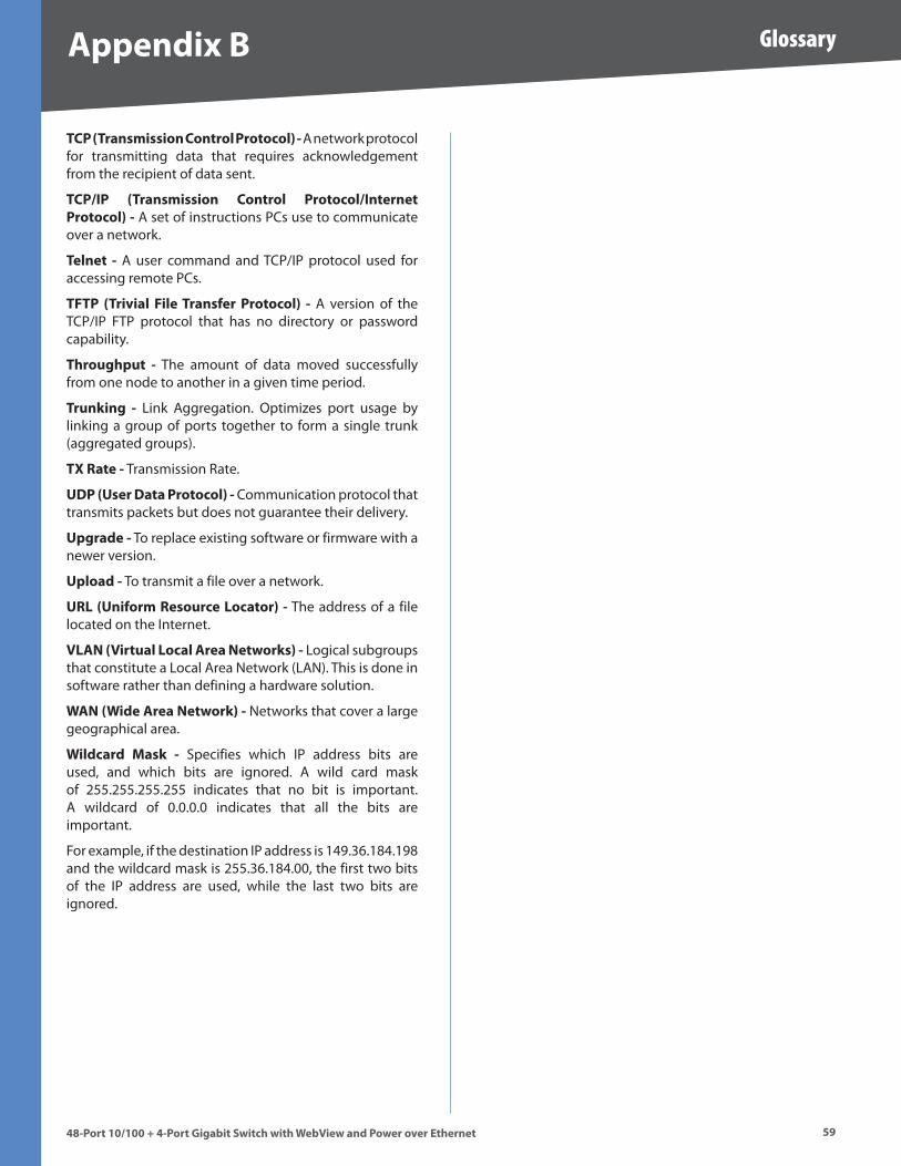
��
Glossary
48-Port 10/100 + 4-Port G�gab�t Sw�tch w�th WebV�ew and Power over Ethernet
Append�x B
TCP (Transm�ss�on Control Protocol) - A network protocol for transmitting data that requires acknowledgement from the recipient of data sent .
TCP/IP (Transm�ss�on Control Protocol/Internet Protocol) - A set of instructions PCs use to communicate over a network .
Telnet - A user command and TCP/IP protocol used for accessing remote PCs .
TFTP (Tr�v�al F�le Transfer Protocol) - A version of the TCP/IP FTP protocol that has no directory or password capability .
Throughput - The amount of data moved successfully from one node to another in a given time period .
Trunk�ng - Link Aggregation . Optimizes port usage by linking a group of ports together to form a single trunk (aggregated groups) .
TX Rate - Transmission Rate .
UDP (User Data Protocol) - Communication protocol that transmits packets but does not guarantee their delivery .
Upgrade - To replace existing software or firmware with a newer version .
Upload - To transmit a file over a network .
URL (Un�form Resource Locator) - The address of a file located on the Internet .
VLAN (V�rtual Local Area Networks) - Logical subgroups that constitute a Local Area Network (LAN) . This is done in software rather than defining a hardware solution .
WAN (W�de Area Network) - Networks that cover a large geographical area .
W�ldcard Mask - Specifies which IP address bits are used, and which bits are ignored . A wild card mask of 255 .255 .255 .255 indicates that no bit is important . A wildcard of 0 .0 .0 .0 indicates that all the bits are important .
For example, if the destination IP address is 149 .36 .184 .198 and the wildcard mask is 255 .36 .184 .00, the first two bits of the IP address are used, while the last two bits are ignored .
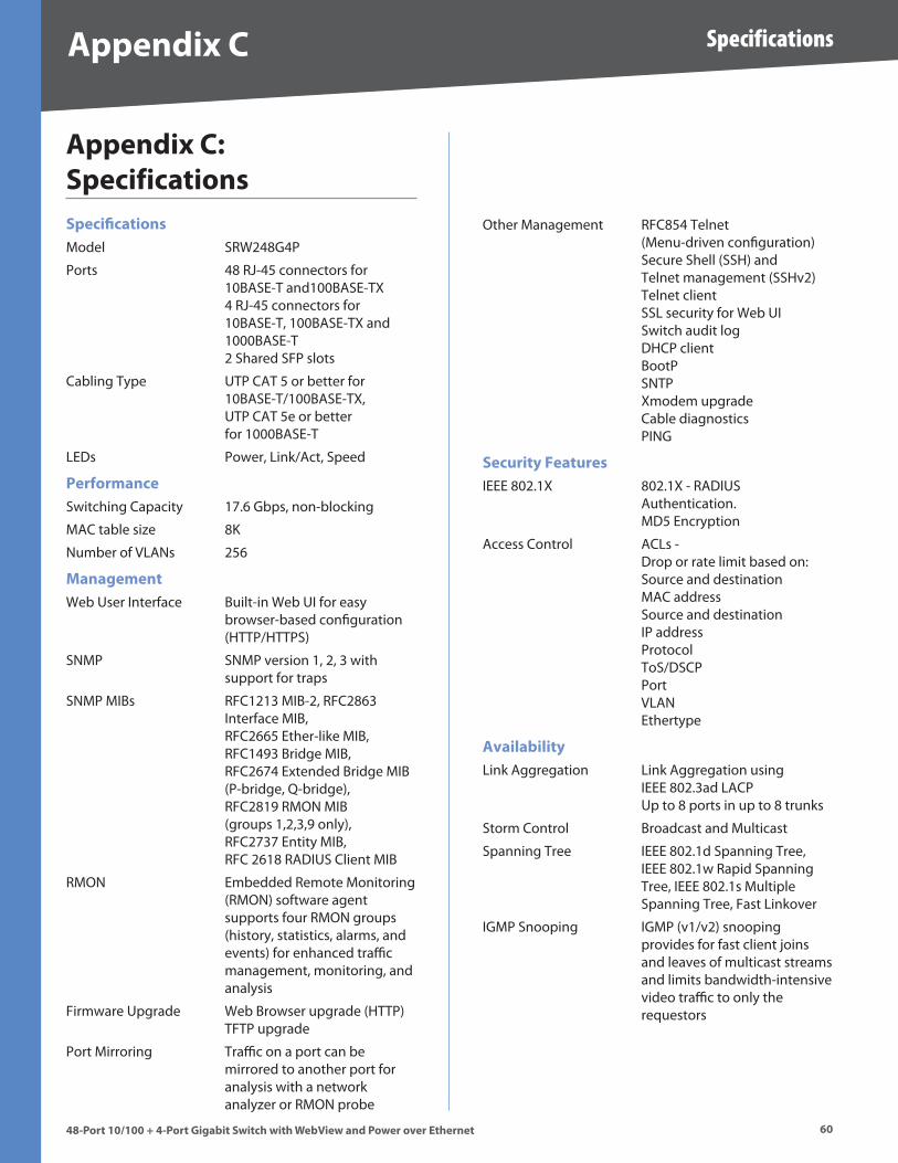
�0
Specifications
48-Port 10/100 + 4-Port G�gab�t Sw�tch w�th WebV�ew and Power over Ethernet
Append�x C
Append�x C: Spec�f�cat�onsSpec�ficat�onsModel SRW248G4P
Ports 48 RJ-45 connectors for 10BASE-T and100BASE-TX 4 RJ-45 connectors for 10BASE-T, 100BASE-TX and 1000BASE-T 2 Shared SFP slots
Cabling Type UTP CAT 5 or better for 10BASE-T/100BASE-TX, UTP CAT 5e or better for 1000BASE-T
LEDs Power, Link/Act, Speed
Performance Switching Capacity 17 .6 Gbps, non-blocking
MAC table size 8K
Number of VLANs 256
ManagementWeb User Interface Built-in Web UI for easy browser-based configuration (HTTP/HTTPS)
SNMP SNMP version 1, 2, 3 with support for traps
SNMP MIBs RFC1213 MIB-2, RFC2863 Interface MIB, RFC2665 Ether-like MIB, RFC1493 Bridge MIB, RFC2674 Extended Bridge MIB (P-bridge, Q-bridge), RFC2819 RMON MIB (groups 1,2,3,9 only), RFC2737 Entity MIB, RFC 2618 RADIUS Client MIB
RMON Embedded Remote Monitoring (RMON) software agent supports four RMON groups (history, statistics, alarms, and events) for enhanced traffic management, monitoring, and analysis
Firmware Upgrade Web Browser upgrade (HTTP) TFTP upgrade
Port Mirroring Traffic on a port can be mirrored to another port for analysis with a network analyzer or RMON probe
Other Management RFC854 Telnet (Menu-driven configuration) Secure Shell (SSH) and Telnet management (SSHv2) Telnet client SSL security for Web UI Switch audit log DHCP client BootP SNTP Xmodem upgrade Cable diagnostics PING
Secur�ty Features IEEE 802 .1X 802 .1X - RADIUS Authentication . MD5 Encryption
Access Control ACLs - Drop or rate limit based on: Source and destination MAC address Source and destination IP address Protocol ToS/DSCP Port VLAN Ethertype
Ava�lab�l�tyLink Aggregation Link Aggregation using IEEE 802 .3ad LACP Up to 8 ports in up to 8 trunks
Storm Control Broadcast and Multicast
Spanning Tree IEEE 802 .1d Spanning Tree, IEEE 802 .1w Rapid Spanning Tree, IEEE 802 .1s Multiple Spanning Tree, Fast Linkover
IGMP Snooping IGMP (v1/v2) snooping provides for fast client joins and leaves of multicast streams and limits bandwidth-intensive video traffic to only the requestors
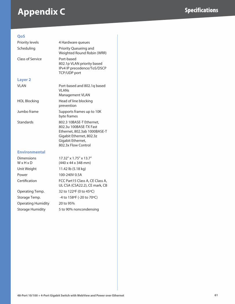
�1
Specifications
48-Port 10/100 + 4-Port G�gab�t Sw�tch w�th WebV�ew and Power over Ethernet
Append�x C
QoSPriority levels 4 Hardware queues
Scheduling Priority Queueing and Weighted Round Robin (WRR)
Class of Service Port-based 802 .1p VLAN priority based IPv4 IP precedence/ToS/DSCP TCP/UDP port
Layer �VLAN Port-based and 802 .1q based VLANs Management VLAN
HOL Blocking Head of line blocking prevention
Jumbo frame Supports frames up to 10K byte frames
Standards 802 .3 10BASE-T Ethernet, 802 .3u 100BASE-TX Fast Ethernet, 802 .3ab 1000BASE-T Gigabit Ethernet, 802 .3z Gigabit Ethernet, 802 .3x Flow Control
Env�ronmentalDimensions 17 .32" x 1 .75" x 13 .7” W x H x D (440 x 44 x 348 mm)
Unit Weight 11 .42 lb (5 .18 kg)
Power 100-240V 0 .5A
Certification FCC Part15 Class A, CE Class A, UL CSA (CSA22 .2), CE mark, CB
Operating Temp . 32 to 122ºF (0 to 45ºC)
Storage Temp . -4 to 158ºF (-20 to 70ºC)
Operating Humidity 20 to 95%
Storage Humidity 5 to 90% noncondensing

��
Warranty and Regulatory Information
48-Port 10/100 + 4-Port G�gab�t Sw�tch w�th WebV�ew and Power over Ethernet
Append�x D
Append�x D: Warranty and Regulatory Informat�on
Limited WarrantyLinksys warrants to You that, for a period of five years (the “Warranty Period”), your Linksys Product will be substantially free of defects in materials and workmanship under normal use . Your exclusive remedy and Linksys’ entire liability under this warranty will be for Linksys at its option to repair or replace the Product or refund Your purchase price less any rebates . This limited warranty extends only to the original purchaser .
If the Product proves defective during the Warranty Period call Linksys Technical Support in order to obtain a Return Authorization Number, if applicable . BE SURE TO HAVE YOUR PROOF OF PURCHASE ON HAND WHEN CALLING . If You are requested to return the Product, mark the Return Authorization Number clearly on the outside of the package and include a copy of your original proof of purchase . RETURN REQUESTS CANNOT BE PROCESSED WITHOUT PROOF OF PURCHASE . You are responsible for shipping defective Products to Linksys . Linksys pays for UPS Ground shipping from Linksys back to You only . Customers located outside of the United States of America and Canada are responsible for all shipping and handling charges .
ALL IMPLIED WARRANTIES AND CONDITIONS OF MERCHANTABILITY OR FITNESS FOR A PARTICULAR PURPOSE ARE LIMITED TO THE DURATION OF THE WARRANTY PERIOD . ALL OTHER EXPRESS OR IMPLIED CONDITIONS, REPRESENTATIONS AND WARRANTIES, INCLUDING ANY IMPLIED WARRANTY OF NON-INFRINGEMENT, ARE DISCLAIMED . Some jurisdictions do not allow limitations on how long an implied warranty lasts, so the above limitation may not apply to You . This warranty gives You specific legal rights, and You may also have other rights which vary by jurisdiction .
This warranty does not apply if the Product (a) has been altered, except by Linksys, (b) has not been installed, operated, repaired, or maintained in accordance with instructions supplied by Linksys, or (c) has been subjected to abnormal physical or electrical stress, misuse, negligence, or accident . In addition, due to the continual development of new techniques for intruding upon and attacking networks, Linksys does not warrant that the Product will be free of vulnerability to intrusion or attack .
TO THE EXTENT NOT PROHIBITED BY LAW, IN NO EVENT WILL LINKSYS BE LIABLE FOR ANY LOST DATA, REVENUE OR PROFIT, OR FOR SPECIAL, INDIRECT, CONSEQUENTIAL, INCIDENTAL OR PUNITIVE DAMAGES, REGARDLESS OF THE THEORY OF LIABILITY (INCLUDING NEGLIGENCE), ARISING OUT OF OR RELATED TO THE USE OF OR INABILITY TO USE THE PRODUCT (INCLUDING ANY SOFTWARE), EVEN IF LINKSYS HAS BEEN ADVISED OF THE POSSIBILITY OF SUCH DAMAGES . IN NO EVENT WILL LINKSYS’ LIABILITY EXCEED THE AMOUNT PAID BY YOU FOR THE PRODUCT . The foregoing limitations will apply even if any warranty or remedy provided under this Agreement fails of its essential purpose . Some jurisdictions do not allow the exclusion or limitation of incidental or consequential damages, so the above limitation or exclusion may not apply to You .
Please direct all inquiries to: Linksys, P .O . Box 18558, Irvine, CA 92623 .

��
Warranty and Regulatory Information
48-Port 10/100 + 4-Port G�gab�t Sw�tch w�th WebV�ew and Power over Ethernet
Append�x D
FCC StatementThis product has been tested and complies with the specifications for a Class B digital device, pursuant to Part 15 of the FCC Rules . These limits are designed to provide reasonable protection against harmful interference in a residential installation . This equipment generates, uses, and can radiate radio frequency energy and, if not installed and used according to the instructions, may cause harmful interference to radio communications . However, there is no guarantee that interference will not occur in a particular installation . If this equipment does cause harmful interference to radio or television reception, which is found by turning the equipment off and on, the user is encouraged to try to correct the interference by one or more of the following measures:
Reorient or relocate the receiving antenna
Increase the separation between the equipment or devices
Connect the equipment to an outlet other than the receiver’s
Consult a dealer or an experienced radio/TV technician for assistance
Safety NoticesCaution: To reduce the risk of fire, use only No .26 AWG or larger telecommunication line cord .
Do not use this product near water, for example, in a wet basement or near a swimming pool .
Avoid using this product during an electrical storm . There may be a remote risk of electric shock from lightning .
WARNING: This product contains lead, known to the State of California to cause cancer, and birth defects or other reproductive harm . Wash hands after handling .
Industry Canada (Canada)This device complies with Industry Canada ICES-003 rule .
Cet appareil est conforme à la norme NMB003 d’Industrie Canada .
IC StatementOperation is subject to the following two conditions:
This device may not cause interference and
This device must accept any interference, including interference that may cause undesired operation of the device .
•
•
•
•
1 .
2 .
Règlement d’Industry CanadaLe fonctionnement est soumis aux conditions suivantes :
Ce périphérique ne doit pas causer d’interférences;
Ce périphérique doit accepter toutes les interférences reçues, y compris celles qui risquent d’entraîner un fonctionnement indésirable .
EC Declaration of Conformity (Europe)In compliance with the EMC Directive 89/336/EEC, Low Voltage Directive 73/23/EEC, and Amendment Directive 93/68/EEC, this product meets the requirements of the following standards:
EN55022 Emission
EN55024 Immunity
EN60950 Safety
1 .
2 .
•
•
•
�4
Warranty and Regulatory Information
48-Port 10/100 + 4-Port G�gab�t Sw�tch w�th WebV�ew and Power over Ethernet
Append�x D
User Information for Consumer Products Covered by EU Directive 2002/96/EC on Waste Electric and Electronic Equipment (WEEE)
This document contains important information for users with regards to the proper disposal and recycling of Linksys products . Consumers are required to comply with this notice for all electronic products bearing the following symbol:
Engl�sh - Env�ronmental Informat�on for Customers �n the European Un�onEuropean Directive 2002/96/EC requires that the equipment
bearing this symbol on the product and/or it’s packaging must not be disposed of with unsorted municipal waste . The symbol indicates that this product should be disposed of separately from regular household waste streams . It is your responsibility to dispose of this and other electric and electronic equipment via designated collection facilities appointed by the government or local authorities . Correct disposal and recycling will help prevent potential negative consequences to the environment and human health . For more detailed information about the disposal of your old equipment, please contact your local authorities, waste disposal service, or the shop where you purchased the product .
Cešt�na (Czech) - Informace o ochraně ž�votního prostředí pro zákazníky v zemích Evropské un�eEvropská směrnice 2002/96/ES zakazuje, aby zařízení
označené tímto symbolem na produktu anebo na obalu bylo likvidováno s netříděným komunálním odpadem . Tento symbol udává, že daný produkt musí být likvidován odděleně od běžného komunálního odpadu . Odpovídáte za likvidaci tohoto produktu a dalších elektrických a elektronických zařízení prostřednictvím určených sběrných míst stanovených vládou nebo místními úřady . Správná likvidace a recyklace pomáhá předcházet potenciálním negativním dopadům na životní prostředí a lidské zdraví . Podrobnější informace o likvidaci starého vybavení si laskavě vyžádejte od místních úřadů, podniku zabývajícího se likvidací komunálních odpadů nebo obchodu, kde jste produkt zakoupili .
Dansk (Dan�sh) - M�ljø�nformat�on for kunder � EUEU-direktiv 2002/96/EF kræver, at udstyr der bærer dette
symbol på produktet og/eller emballagen ikke må bortskaffes som usorteret kommunalt affald . Symbolet betyder, at dette produkt skal bortskaffes adskilt fra det almindelige husholdningsaffald . Det er dit ansvar at bortskaffe dette og andet elektrisk og elektronisk udstyr via bestemte indsamlingssteder udpeget af staten eller de lokale myndigheder . Korrekt bortskaffelse og genvinding vil hjælpe med til at undgå mulige skader for miljøet og menneskers sundhed . Kontakt venligst de lokale myndigheder, renovationstjenesten eller den butik, hvor du har købt produktet, angående mere detaljeret information om bortskaffelse af dit gamle udstyr .
Deutsch (German) - Umwelt�nformat�on für Kunden �nnerhalb der Europä�schen Un�onDie Europäische Richtlinie 2002/96/EC verlangt, dass technische Ausrüstung, die direkt am Gerät und/oder an der Verpackung
mit diesem Symbol versehen ist , nicht zusammen mit unsortiertem Gemeindeabfall entsorgt werden darf . Das Symbol weist darauf hin, dass das Produkt von regulärem Haushaltmüll getrennt entsorgt werden sollte . Es liegt in Ihrer Verantwortung, dieses Gerät und andere elektrische und elektronische Geräte über die dafür zuständigen und von der Regierung oder örtlichen Behörden dazu bestimmten Sammelstellen zu entsorgen . Ordnungsgemäßes Entsorgen und Recyceln trägt dazu bei, potentielle negative Folgen für Umwelt und die menschliche Gesundheit zu vermeiden . Wenn Sie weitere Informationen zur Entsorgung Ihrer Altgeräte benötigen, wenden Sie sich bitte an die örtlichen Behörden oder städtischen Entsorgungsdienste oder an den Händler, bei dem Sie das Produkt erworben haben .
Eest� (Eston�an) - Keskkonnaalane �nformats�oon Euroopa L��dus asuvatele kl�ent�deleEuroopa Liidu direktiivi 2002/96/EÜ nõuete kohaselt on
seadmeid, millel on tootel või pakendil käesolev sümbol , keelatud kõrvaldada koos sorteerimata olmejäätmetega . See sümbol näitab, et toode tuleks kõrvaldada eraldi tavalistest olmejäätmevoogudest . Olete kohustatud kõrvaldama käesoleva ja ka muud elektri- ja elektroonikaseadmed riigi või kohalike ametiasutuste poolt ette nähtud kogumispunktide kaudu . Seadmete korrektne kõrvaldamine ja ringlussevõtt aitab vältida võimalikke negatiivseid tagajärgi keskkonnale ning inimeste tervisele . Vanade seadmete kõrvaldamise kohta täpsema informatsiooni saamiseks võtke palun ühendust kohalike ametiasutustega, jäätmekäitlusfirmaga või kauplusega, kust te toote ostsite .
��
Warranty and Regulatory Information
48-Port 10/100 + 4-Port G�gab�t Sw�tch w�th WebV�ew and Power over Ethernet
Append�x D
Español (Span�sh) - Informac�ón med�oamb�ental para cl�entes de la Un�ón EuropeaLa Directiva 2002/96/CE de la UE exige que los equipos que
lleven este símbolo en el propio aparato y/o en su embalaje no deben eliminarse junto con otros residuos urbanos no seleccionados . El símbolo indica que el producto en cuestión debe separarse de los residuos domésticos convencionales con vistas a su eliminación . Es responsabilidad suya desechar este y cualesquiera otros aparatos eléctricos y electrónicos a través de los puntos de recogida que ponen a su disposición el gobierno y las autoridades locales . Al desechar y reciclar correctamente estos aparatos estará contribuyendo a evitar posibles consecuencias negativas para el medio ambiente y la salud de las personas . Si desea obtener información más detallada sobre la eliminación segura de su aparato usado, consulte a las autoridades locales, al servicio de recogida y eliminación de residuos de su zona o pregunte en la tienda donde adquirió el producto .
ξλληνικά (Greek) - Στοιχεία περιβαλλοντικής προστασίας για πελάτες εντός της Ευρωπαϊκής ΈνωσηςΗ Κοινοτική Οδηγία 2002/96/EC απαιτεί ότι ο εξοπλισμός
ο οποίος φέρει αυτό το σύμβολο στο προϊόν και/ή στη συσκευασία του δεν πρέπει να απορρίπτεται μαζί με τα μικτά κοινοτικά απορρίμματα . Το σύμβολο υποδεικνύει ότι αυτό το προϊόν θα πρέπει να απορρίπτεται ξεχωριστά από τα συνήθη οικιακά απορρίμματα . Είστε υπεύθυνος για την απόρριψη του παρόντος και άλλου ηλεκτρικού και ηλεκτρονικού εξοπλισμού μέσω των καθορισμένων εγκαταστάσεων συγκέντρωσης απορριμμάτων οι οποίες παρέχονται από το κράτος ή τις αρμόδιες τοπικές αρχές . Η σωστή απόρριψη και ανακύκλωση συμβάλλει στην πρόληψη πιθανών αρνητικών συνεπειών για το περιβάλλον και την υγεία . Για περισσότερες πληροφορίες σχετικά με την απόρριψη του παλιού σας εξοπλισμού, παρακαλώ επικοινωνήστε με τις τοπικές αρχές, τις υπηρεσίες απόρριψης ή το κατάστημα από το οποίο αγοράσατε το προϊόν .
França�s (French) - Informat�ons env�ronnementales pour les cl�ents de l’Un�on européenneLa directive européenne 2002/96/CE exige que l’équipement
sur lequel est apposé ce symbole sur le produit et/ou son emballage ne soit pas jeté avec les autres ordures ménagères . Ce symbole indique que le produit doit être éliminé dans un circuit distinct de celui pour les déchets des ménages . Il est de votre responsabilité de jeter ce matériel ainsi que tout autre matériel électrique ou électronique par les moyens de collecte indiqués par le gouvernement et les pouvoirs publics des collectivités territoriales . L’élimination et le recyclage en bonne et due forme ont pour but de lutter contre l’impact néfaste potentiel de ce type de produits sur l’environnement et la santé publique . Pour plus d’informations sur le mode d’élimination de votre ancien équipement, veuillez prendre contact avec les pouvoirs publics locaux, le service de traitement des déchets, ou l’endroit où vous avez acheté le produit .
Ital�ano (Ital�an) - Informaz�on� relat�ve all’amb�ente per � cl�ent� res�dent� nell’Un�one EuropeaLa direttiva europea 2002/96/EC richiede che le
apparecchiature contrassegnate con questo simbolo sul prodotto e/o sull’imballaggio non siano smaltite insieme ai rifiuti urbani non differenziati . Il simbolo indica che questo prodotto non deve essere smaltito insieme ai normali rifiuti domestici . È responsabilità del proprietario smaltire sia questi prodotti sia le altre apparecchiature elettriche ed elettroniche mediante le specifiche strutture di raccolta indicate dal governo o dagli enti pubblici locali . Il corretto smaltimento ed il riciclaggio aiuteranno a prevenire conseguenze potenzialmente negative per l’ambiente e per la salute dell’essere umano . Per ricevere informazioni più dettagliate circa lo smaltimento delle vecchie apparecchiature in Vostro possesso, Vi invitiamo a contattare gli enti pubblici di competenza, il servizio di smaltimento rifiuti o il negozio nel quale avete acquistato il prodotto .
Latv�ešu valoda (Latv�an) - Ekoloģ�ska �nformāc�ja kl�ent�em E�ropas Sav�enības jur�sd�kc�jāDirektīvā 2002/96/EK ir prasība, ka aprīkojumu, kam pievienota
zīme uz paša izstrādājuma vai uz tā iesaiņojuma, nedrīkst izmest nešķirotā veidā kopā ar komunālajiem atkritumiem (tiem, ko rada vietēji iedzīvotāji un uzņēmumi) . Šī zīme nozīmē to, ka šī ierīce ir jāizmet atkritumos tā, lai tā nenonāktu kopā ar parastiem mājsaimniecības atkritumiem . Jūsu pienākums ir šo un citas elektriskas un elektroniskas ierīces izmest atkritumos, izmantojot īpašus atkritumu savākšanas veidus un līdzekļus, ko nodrošina valsts un pašvaldību iestādes . Ja izmešana atkritumos un pārstrāde tiek veikta pareizi, tad mazinās iespējamais kaitējums dabai un cilvēku veselībai . Sīkākas ziņas par novecojuša aprīkojuma izmešanu atkritumos jūs varat saņemt vietējā pašvaldībā, atkritumu savākšanas dienestā, kā arī veikalā, kur iegādājāties šo izstrādājumu .
L�etuvška� (L�thuan�an) - Apl�nkosaugos �nformac�ja, sk�rta Europos Sąjungos vartotojams
Europos direktyva 2002/96/EC numato, kad įrangos, kuri ir kurios pakuotė yra pažymėta šiuo simboliu (įveskite simbolį), negalima šalinti kartu su nerūšiuotomis komunalinėmis atliekomis . Šis simbolis rodo, kad gaminį reikia šalinti atskirai nuo bendro buitinių atliekų srauto . Jūs privalote užtikrinti, kad ši ir kita elektros ar elektroninė įranga būtų šalinama per tam tikras nacionalinės ar vietinės valdžios nustatytas atliekų rinkimo sistemas . Tinkamai šalinant ir perdirbant atliekas, bus išvengta galimos žalos aplinkai ir žmonių sveikatai . Daugiau informacijos apie jūsų senos įrangos šalinimą gali pateikti vietinės valdžios institucijos, atliekų šalinimo tarnybos arba parduotuvės, kuriose įsigijote tą gaminį .
��
Warranty and Regulatory Information
48-Port 10/100 + 4-Port G�gab�t Sw�tch w�th WebV�ew and Power over Ethernet
Append�x D
Malt� (Maltese) - Informazzjon� Ambjental� għal Kl�jent� fl-Unjon� Ewropea Id-Direttiva Ewropea 2002/96/KE titlob li t-tagħmir li jkun fih
is-simbolu fuq il-prodott u/jew fuq l-ippakkjar ma jistax jintrema ma’ skart muniċipali li ma ġiex isseparat . Is-simbolu jindika li dan il-prodott għandu jintrema separatament minn ma’ l-iskart domestiku regolari . Hija responsabbiltà tiegħek li tarmi dan it-tagħmir u kull tagħmir ieħor ta’ l-elettriku u elettroniku permezz ta’ faċilitajiet ta’ ġbir appuntati apposta mill-gvern jew mill-awtoritajiet lokali . Ir-rimi b’mod korrett u r-riċiklaġġ jgħin jipprevjeni konsegwenzi negattivi potenzjali għall-ambjent u għas-saħħa tal-bniedem . Għal aktar informazzjoni dettaljata dwar ir-rimi tat-tagħmir antik tiegħek, jekk jogħġbok ikkuntattja lill-awtoritajiet lokali tiegħek, is-servizzi għar-rimi ta’ l-iskart, jew il-ħanut minn fejn xtrajt il-prodott .
Magyar (Hungar�an) - Környezetvédelm� �nformác�ó az európa� un�ós vásárlók számáraA 2002/96/EC számú európai uniós irányelv megkívánja, hogy azokat a termékeket, amelyeken, és/vagy amelyek
csomagolásán az alábbi címke megjelenik, tilos a többi szelektálatlan lakossági hulladékkal együtt kidobni . A címke azt jelöli, hogy az adott termék kidobásakor a szokványos háztartási hulladékelszállítási rendszerektõl elkülönített eljárást kell alkalmazni . Az Ön felelõssége, hogy ezt, és más elektromos és elektronikus berendezéseit a kormányzati vagy a helyi hatóságok által kijelölt gyűjtõredszereken keresztül számolja fel . A megfelelõ hulladékfeldolgozás segít a környezetre és az emberi egészségre potenciálisan ártalmas negatív hatások megelõzésében . Ha elavult berendezéseinek felszámolásához további részletes információra van szüksége, kérjük, lépjen kapcsolatba a helyi hatóságokkal, a hulladékfeldolgozási szolgálattal, vagy azzal üzlettel, ahol a terméket vásárolta .
Nederlands (Dutch) - M�l�eu-�nformat�e voor klanten �n de Europese Un�eDe Europese Richtlijn 2002/96/EC schrijft voor dat apparatuur
die is voorzien van dit symbool op het product of de verpakking, niet mag worden ingezameld met niet-gescheiden huishoudelijk afval . Dit symbool geeft aan dat het product apart moet worden ingezameld . U bent zelf verantwoordelijk voor de vernietiging van deze en andere elektrische en elektronische apparatuur via de daarvoor door de landelijke of plaatselijke overheid aangewezen inzamelingskanalen . De juiste vernietiging en recycling van deze apparatuur voorkomt mogelijke negatieve gevolgen voor het milieu en de gezondheid . Voor meer informatie over het vernietigen van uw oude apparatuur neemt u contact op met de plaatselijke autoriteiten of afvalverwerkingsdienst, of met de winkel waar u het product hebt aangeschaft .
Norsk (Norweg�an) - M�ljø�nformasjon for kunder � EUEU-direktiv 2002/96/EF krever at utstyr med følgende symbol
avbildet på produktet og/eller pakningen, ikke må kastes sammen med usortert avfall . Symbolet indikerer at dette produktet skal håndteres atskilt fra ordinær avfallsinnsamling for husholdningsavfall . Det er ditt ansvar å kvitte deg med dette produktet og annet elektrisk og elektronisk avfall via egne innsamlingsordninger slik myndighetene eller kommunene bestemmer . Korrekt avfallshåndtering og gjenvinning vil være med på å forhindre mulige negative konsekvenser for miljø og helse . For nærmere informasjon om håndtering av det kasserte utstyret ditt, kan du ta kontakt med kommunen, en innsamlingsstasjon for avfall eller butikken der du kjøpte produktet .
Polsk� (Pol�sh) - Informacja dla kl�entów w Un�� Europejsk�ej o przep�sach dotyczących ochrony środow�skaDyrektywa Europejska 2002/96/EC wymaga, aby sprzęt
oznaczony symbolem znajdującym się na produkcie i/lub jego opakowaniu nie był wyrzucany razem z innymi niesortowanymi odpadami komunalnymi . Symbol ten wskazuje, że produkt nie powinien być usuwany razem ze zwykłymi odpadami z gospodarstw domowych . Na Państwu spoczywa obowiązek wyrzucania tego i innych urządzeń elektrycznych oraz elektronicznych w punktach odbioru wyznaczonych przez władze krajowe lub lokalne . Pozbywanie się sprzętu we właściwy sposób i jego recykling pomogą zapobiec potencjalnie negatywnym konsekwencjom dla środowiska i zdrowia ludzkiego . W celu uzyskania szczegółowych informacji o usuwaniu starego sprzętu, prosimy zwrócić się do lokalnych władz, służb oczyszczania miasta lub sklepu, w którym produkt został nabyty .
Português (Portuguese) - Informação amb�ental para cl�entes da Un�ão Europe�aA Directiva Europeia 2002/96/CE exige que o equipamento que
exibe este símbolo no produto e/ou na sua embalagem não seja eliminado junto com os resíduos municipais não separados . O símbolo indica que este produto deve ser eliminado separadamente dos resíduos domésticos regulares . É da sua responsabilidade eliminar este e qualquer outro equipamento eléctrico e electrónico através dos instalações de recolha designadas pelas autoridades governamentais ou locais . A eliminação e reciclagem correctas ajudarão a prevenir as consequências negativas para o ambiente e para a saúde humana . Para obter informações mais detalhadas sobre a forma de eliminar o seu equipamento antigo, contacte as autoridades locais, os serviços de eliminação de resíduos ou o estabelecimento comercial onde adquiriu o produto .
��
Warranty and Regulatory Information
48-Port 10/100 + 4-Port G�gab�t Sw�tch w�th WebV�ew and Power over Ethernet
Append�x D
Slovenč�na (Slovak) - Informác�e o ochrane ž�votného prostred�a pre zákazníkov v Európskej ún��Podľa európskej smernice 2002/96/ES zariadenie s týmto
symbolom na produkte a/alebo jeho balení nesmie byť likvidované spolu s netriedeným komunálnym odpadom . Symbol znamená, že produkt by sa mal likvidovať oddelene od bežného odpadu z domácností . Je vašou povinnosťou likvidovať toto i ostatné elektrické a elektronické zariadenia prostredníctvom špecializovaných zberných zariadení určených vládou alebo miestnymi orgánmi . Správna likvidácia a recyklácia pomôže zabrániť prípadným negatívnym dopadom na životné prostredie a zdravie ľudí . Ak máte záujem o podrobnejšie informácie o likvidácii starého zariadenia, obráťte sa, prosím, na miestne orgány, organizácie zaoberajúce sa likvidáciou odpadov alebo obchod, v ktorom ste si produkt zakúpili .
Slovenč�na (Slovene) - Okoljske �nformac�je za stranke v Evropsk� un�j�Evropska direktiva 2002/96/EC prepoveduje odlaganje opreme,
označene s tem simbolom – na izdelku in/ali na embalaži – med običajne, nerazvrščene odpadke . Ta simbol opozarja, da je treba izdelek odvreči ločeno od preostalih gospodinjskih odpadkov . Vaša odgovornost je, da to in preostalo električno in elektronsko opremo odnesete na posebna zbirališča, ki jih določijo državne ustanove ali lokalna uprava . S pravilnim odlaganjem in recikliranjem boste preprečili morebitne škodljive vplive na okolje in zdravje ljudi . Če želite izvedeti več o odlaganju stare opreme, se obrnite na lokalno upravo, odpad ali trgovino, kjer ste izdelek kupili .
Suom� (F�nn�sh) - Ympär�stöä koskev�a t�etoja EU-alueen as�akka�lleEU-direktiivi 2002/96/EY edellyttää, että jos laitteistossa on
tämä symboli itse tuotteessa ja/tai sen pakkauksessa, laitteistoa ei saa hävittää lajittelemattoman yhdyskuntajätteen mukana . Symboli merkitsee sitä, että tämä tuote on hävitettävä erillään tavallisesta kotitalousjätteestä . Sinun vastuullasi on hävittää tämä elektroniikkatuote ja muut vastaavat elektroniikkatuotteet viemällä tuote tai tuotteet viranomaisten määräämään keräyspisteeseen . Laitteiston oikea hävittäminen estää mahdolliset kielteiset vaikutukset ympäristöön ja ihmisten terveyteen . Lisätietoja vanhan laitteiston oikeasta hävitystavasta saa paikallisilta viranomaisilta, jätteenhävityspalvelusta tai siitä myymälästä, josta ostit tuotteen .
Svenska (Swed�sh) - M�ljö�nformat�on för kunder � Europe�ska un�onenDet europeiska direktivet 2002/96/EC kräver att utrustning
med denna symbol på produkten och/eller förpackningen inte får kastas med osorterat kommunalt avfall . Symbolen visar att denna produkt bör kastas efter att den avskiljts från vanligt hushållsavfall . Det faller på ditt ansvar att kasta denna och annan elektrisk och elektronisk utrustning på fastställda insamlingsplatser utsedda av regeringen eller lokala myndigheter . Korrekt kassering och återvinning skyddar mot eventuella negativa konsekvenser för miljön och personhälsa . För mer detaljerad information om kassering av din gamla utrustning kontaktar du dina lokala myndigheter, avfallshanteringen eller butiken där du köpte produkten .
WEB: For additional information, please visit www.l�nksys.com
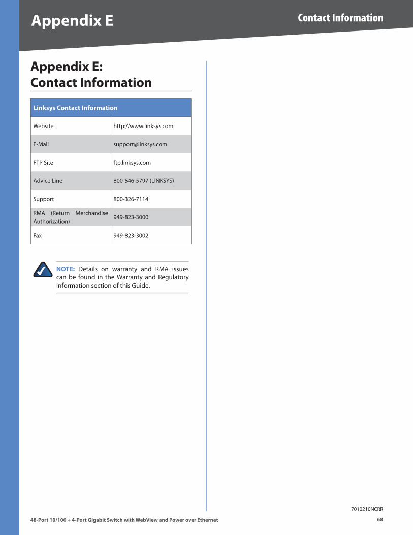
�8
Contact Information
48-Port 10/100 + 4-Port G�gab�t Sw�tch w�th WebV�ew and Power over Ethernet
Append�x E
Append�x E: Contact Informat�on
L�nksys Contact Informat�on
Website http://www .linksys .com
E-Mail support@linksys .com
FTP Site ftp .linksys .com
Advice Line 800-546-5797 (LINKSYS)
Support 800-326-7114
RMA (Return Merchandise Authorization)
949-823-3000
Fax 949-823-3002
NOTE: Details on warranty and RMA issues can be found in the Warranty and Regulatory Information section of this Guide .
7010210NCRR