Embed Size (px)
Citation preview
CATALOG No.249-6E
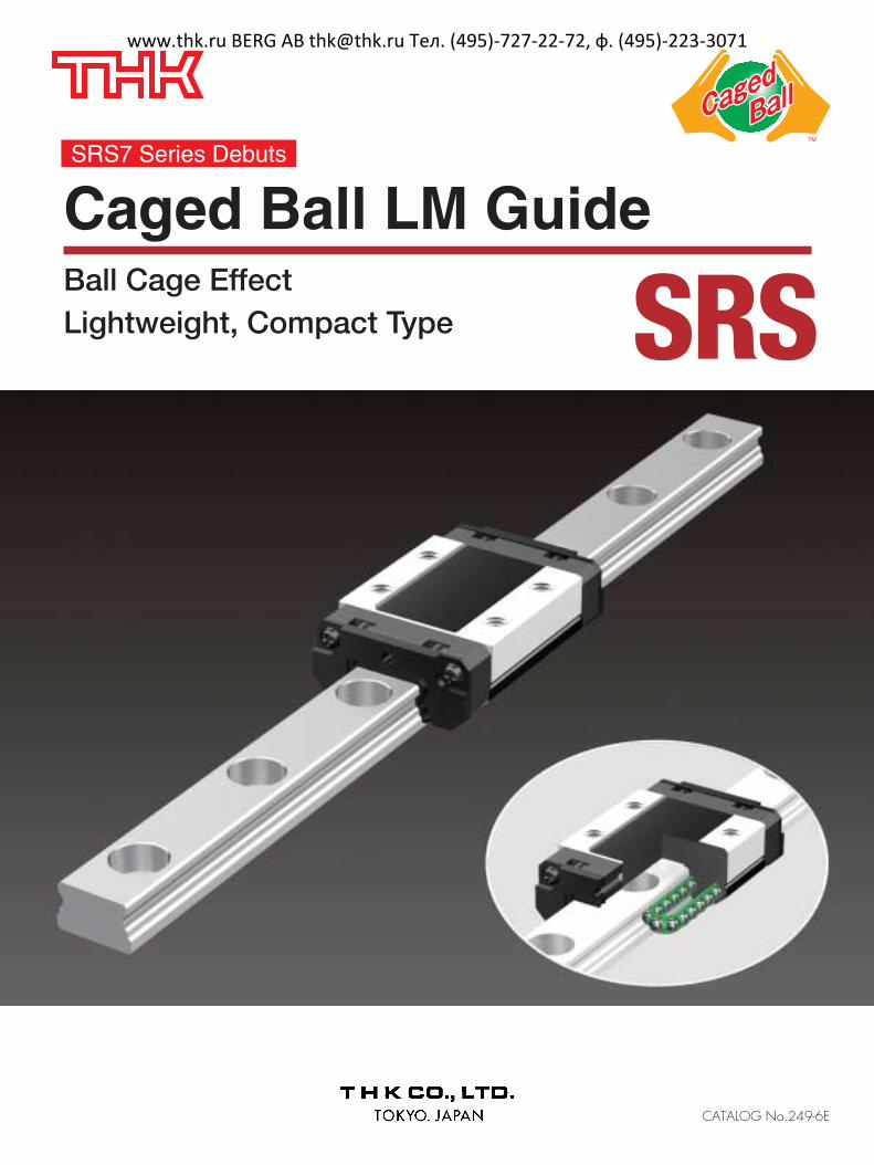
Caged Ball LM GuideBall Cage EffectLightweight, Compact Type SRS
SRS7 Series Debuts
www.thk.ru BERG AB [email protected] Тел. (495)-727-22-72, ф. (495)-223-3071

1
Rotary ball bearing
Conventional structure Caged Ball structure
With the Caged Ball LM Guide, the use of a ball cageallows lines of evenly spaced balls to circulate, thus toeliminating friction between the balls. In addition, grease held in a space between the ballcirculation path and the ball cage (grease pocket) isapplied on the contact surface between each ball andthe ball cage as the ball rotates, forming an oil film onthe ball surface. This minimizes the risk of oil-filmbreak.
Caged Ball LM Guide
Extremely low bearing stressachieved with ball-to-cage contact
Oil-film contact
Conventional structure●Adjacent balls contact each other
at a point. As a result, contactstress is high and the oil filmbreaks due to friction.●The service life becomes shorter.
Caged Ball structure●The service life is prolonged due to the elimination of wear caused
by friction between balls.●The absence of friction between balls results in reduced heat
generation during high-speed rotation.●The absence of friction between balls eliminates collision noise of
the balls.●The even spacing of the balls enables them to move smoothly.●Retention of lubricant in the ball cage ensures a long service life.
Ball
High bearing stress due toball-to-ball contact
Ball Cage EffectThe early forms of ball bearings were full-ball types without ball cages. Friction between balls caused loudnoise, made high-speed rotation impossible and shortened the service life. Twenty years later, a Caged Balldesign was developed for ball bearings. The new design enabled high-speed rotation at a low noise level,and extended the service life despite the reduced number of balls used. It marked a major development inthe history of ball bearings. Similarly, the quality of needle bearings was significantly improved by the caged needle structure.With cage-less, full-ball types of ball bearings, balls make metallic contact with one another andproduce loud noise. In addition, they rotate in opposite directions, causing the sliding contact between twoadjacent balls to occur at a speed twice the ball-spinning rate. It results in severe wear and shortens theservice life. In addition, without a cage, balls make point contact to increase bearing stress, thus facilitatingbreakage of the oil film. In contrast, each caged ball contacts the cage over a wide area. Therefore, the oilfilm does not break, the noise level is low and balls can rotate at a high speed, resulting in a longservice life.
Long Service Life and Long-termMaintenance-free Operation
Superbly High Speed
Low Noise, Acceptable Running Sound
Smooth Motion
Low Dust Generation
www.thk.ru BERG AB [email protected] Тел. (495)-727-22-72, ф. (495)-223-3071
2
Lightweight, Compact TypeCaged Ball LM Guide SRS
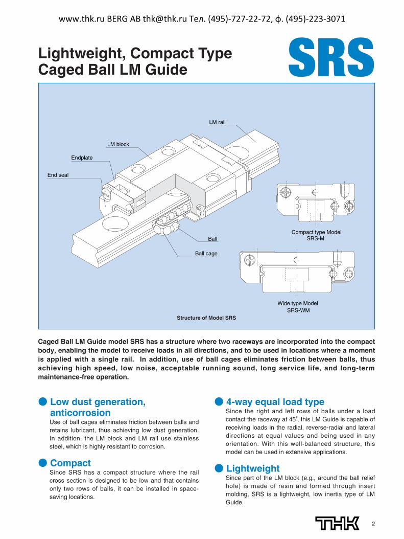
Ball cage
Ball
End seal
Endplate
LM block
LM rail
Compact type ModelSRS-M
Wide type ModelSRS-WM
Structure of Model SRS
Caged Ball LM Guide model SRS has a structure where two raceways are incorporated into the compactbody, enabling the model to receive loads in all directions, and to be used in locations where a momentis applied with a single rail. In addition, use of ball cages eliminates friction between balls, thusachieving high speed, low noise, acceptable running sound, long service life, and long-termmaintenance-free operation.
● Low dust generation,anticorrosionUse of ball cages eliminates friction between balls andretains lubricant, thus achieving low dust generation.In addition, the LM block and LM rail use stainlesssteel, which is highly resistant to corrosion.
● CompactSince SRS has a compact structure where the railcross section is designed to be low and that containsonly two rows of balls, it can be installed in space-saving locations.
● 4-way equal load typeSince the right and left rows of balls under a loadcontact the raceway at 45°, this LM Guide is capable ofreceiving loads in the radial, reverse-radial and lateraldirections at equal values and being used in anyorientation. With this well-balanced structure, thismodel can be used in extensive applications.
● LightweightSince part of the LM block (e.g., around the ball reliefhole) is made of resin and formed through insertmolding, SRS is a lightweight, low inertia type of LMGuide.
www.thk.ru BERG AB [email protected] Тел. (495)-727-22-72, ф. (495)-223-3071
3
SRS OutlineModel SRS - Product Overview
●SRS 7M ●SRS 15M●SRS 9M ●SRS 20M●SRS 12M ●SRS 25M
Model SRS-MStandard type
Note: Full-ball type (with noball cage) for modelsSRS-M/WM is alsoavailable. If desiringthe full-ball type, specify“SRS-G”type whenmaking an order.However, since SRS-G type does not havea ball cage, its dynamicload rating is smallerthan models SRS-M/WM.
●SRS 7WM ●SRS 15WM●SRS 9WM●SRS 12WM
Model SRS-WMWide type
It has a longer overall LM blocklength (L), a greater width and alarger rated load and permissiblemoment than SRS-M.
A standard type of SRS.
W
L
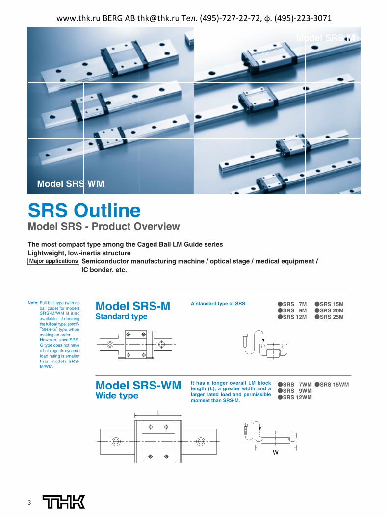
Model SRS WM
Model SRS M
The most compact type among the Caged Ball LM Guide seriesLightweight, low-inertia structureMajor applications Semiconductor manufacturing machine / optical stage / medical equipment /
IC bonder, etc.
www.thk.ru BERG AB [email protected] Тел. (495)-727-22-72, ф. (495)-223-3071
4
*1:Dimensional table formodel SRS
Model SRS-M→ pages 9-10
Model SRS-MW→ pages 11-12
SRS OUTLINEModel SRS - Product Overview
where PE :Equivalent load (N)
⋅Radial direction⋅Reverse-radial direction⋅Lateral direction
PR :Radial load (N)PL :Reverse-radial load (N)PT :Lateral load (N)X, Y:Equivalent factor
(see the table below)
PE=X・PR(PL)+Y・PT
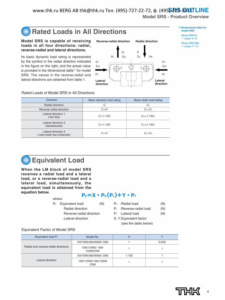
Rated Loads in All DirectionsModel SRS is capable of receivingloads in all four directions: radial,reverse-radial and lateral directions.
Its basic dynamic load rating is representedby the symbol in the radial direction indicatedin the figure on the right, and the actual valueis provided in the dimensional table*1 for modelSRS. The values in the reverse-radial andlateral directions are obtained from table 1.
Equivalent LoadWhen the LM block of model SRSreceives a radial load and a lateralload, or a reverse-radial load and alateral load, simultaneously, theequivalent load is obtained from theequation below.
CL
CT
C0L
C0T
CT
C0T
C
C0PL PR
PT PT
Radial directionReverse-radial direction
Lateral direction
Lateral direction
Rated Loads of Model SRS in All Directions
Direction
Radial direction
Reverse-radial direction
Lateral direction 1(7M/7WM)
Lateral direction 2(9M/9WM/20M)
Lateral direction 3(12M/12WM/15M/15WM/25M)
Basic dynamic load rating
C
CL=C
CT=1.13C
CT=1.19C
CT=C
C0
C0L=C0
C0T=1.19C0
C0T=1.19C0
C0T=C0
Basic static load rating
Equivalent Factor of Model SRS
Radial and reverse-radial directions
Lateral direction
Equivalent load PE
7M/7MW/9M/9WM/ 20M
12M/12WM/ 15M/15WM/25M
7M/7MW/9M/9WM/ 20M
12M/12WM/15M/15WM/25M
Model No. X
1
1
1.192
1
Y
0.839
1
1
1
www.thk.ru BERG AB [email protected] Тел. (495)-727-22-72, ф. (495)-223-3071

5
The service life of an LM Guide is subject to variations even under the sameoperational conditions. Therefore, it is necessary to use the rated life definedbelow as a reference value for obtaining the service life of the LM Guide.
1.0
0.9
0.8
0.7
0.6
0.5
0.4
0.3
0.2
0.1
60 50 40 30 20 10Raceway hardness (HRC)
Har
dn
ess
fact
or
fH
0.8
0.9
1.0
0.7
0.6
0.5
100 150 200Raceway temperature (°C)
Tem
per
atu
re f
acto
r fT
Fig. 1 Fig. 2
■fH:Hardness factorTo ensure the achievement of the optimum load capacity of the LM Guide,the raceway hardness must be between 58 and 64 HRC.At hardness below this range, the basic dynamic and static load ratingsdecrease. Therefore, the rating values must be multiplied by therespective hardness factors (fH).Since the LM Guide has sufficient hardness, the fH value for the LM Guideis normally 1.0 unless otherwise specified.
■fC:Contact factorWhen multiple LM blocks are used in close contact with each other, it isdifficult to achieve uniform load distribution due to moment loads andmounting-surface accuracy. When using multiple blocks in close contactwith each other, multiply the basic load rating (C or C0) by thecorresponding contact factor indicated in Table 1.Note: When uneven load distribution is expected in a large machine, consider using a contact
factor from Table 1.
■fT:Temperature factorSince the service temperature of Caged Ball LM Guides is normally 80°Cor below, the fT value is 1.0.
■fW:Load factorIn general, reciprocating machines tend to produce vibrations or impactduring operation. It is especially difficult to accurately determine allvibrations generated during high-speed operation and impacts producedeach time the machine starts and stops. Therefore, where the effects ofspeed and vibration are estimated to be significant, divide the basicdynamic load rating (C) by a load factor selected from Table 2, whichcontains empirically obtained data.
●Rated lifeThe rated life means the total travel distancethat 90% of a group of units of the same LMGuide model can achieve without flaking(scale-like exfoliation on the metal surface)after individually running under the sameconditions.
●Service life timeOnce the rated life (L) has been obtained, theservice life time can be obtained using theequation on the right if the stroke length andthe number of reciprocations are constant.
L = ( · )3 50CPC
fH · fT · fC
fW
Lh =L 106
2 RS n1 60
L : Rated life (km)C : Basic dynamic load rating*1 (N)PC : Calculated load (N)fH : Hardness factor (see Fig. 1)fT : Temperature factor (see Fig. 2)fC : Contact factor (see Table 1)fW : Load factor (see Table 2)
Lh : Service life time (h)Rs : Stroke length (mm)n1 : No. of reciprocations per min (min-1)
Table 1 Contact Factor (fC) Table 2 Load Factor(fW)
Number of blocks used in close contact
2
3
4
5
6 or more
Normal use
Contact factor fC
0.81
0.72
0.66
0.61
0.6
1
Faint
Weak
Moderate
Strong
Very slowV≦0.25m/s
Slow0.25<V≦1m/s
Medium1<V≦2m/s
FastV>2m/s
1 to 1.2
1.2 to 1.5
1.5 to 2
2 to 3.5
Vibration/impact Speed (V) fW
*1: Basic dynamic load rating(C)
It refers to a load with aconstant magnitude anddirection under which therated life (L) of a group ofidentical LM Guide unitsindependently operating is50 km.
Service life
www.thk.ru BERG AB [email protected] Тел. (495)-727-22-72, ф. (495)-223-3071
6
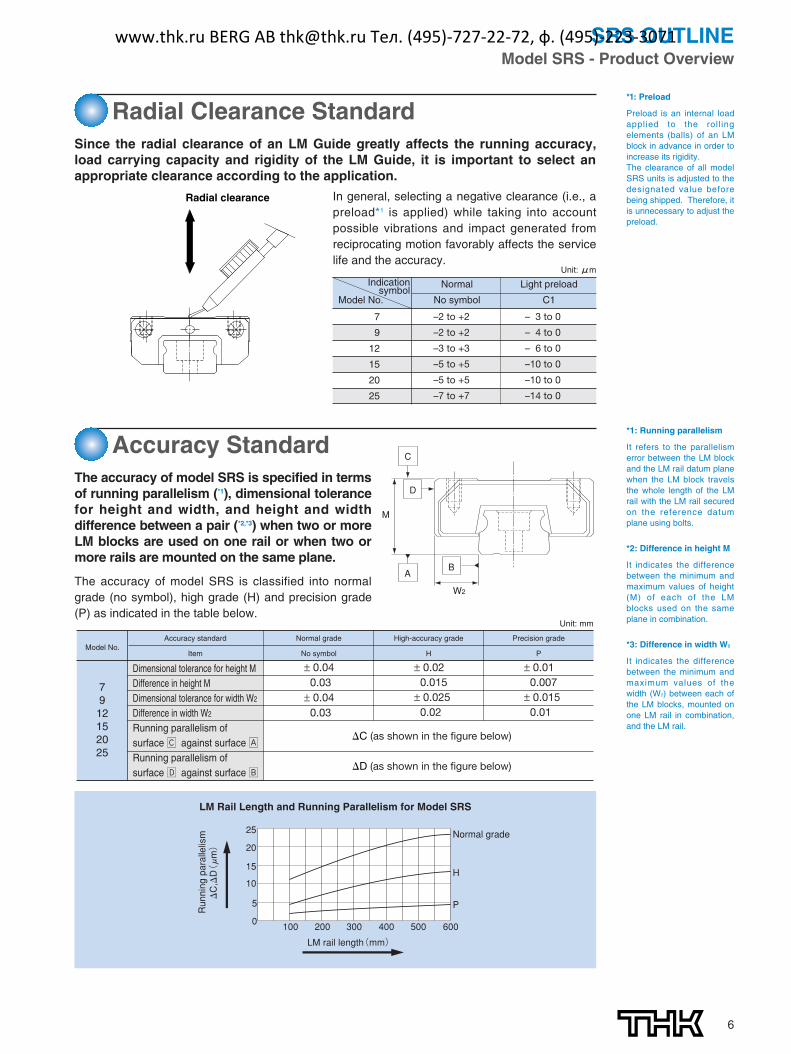
*1: Running parallelism
It refers to the parallelismerror between the LM blockand the LM rail datum planewhen the LM block travelsthe whole length of the LMrail with the LM rail securedon the reference datumplane using bolts.
*2: Difference in height M
It indicates the differencebetween the minimum andmaximum values of height(M) of each of the LMblocks used on the sameplane in combination.
*3: Difference in width W2
It indicates the differencebetween the minimum andmaximum values of thewidth (W2) between each ofthe LM blocks, mounted onone LM rail in combination,and the LM rail.
SRS OUTLINEModel SRS - Product Overview
The accuracy of model SRS is specified in termsof running parallelism (*1), dimensional tolerancefor height and width, and height and widthdifference between a pair (*2,*3) when two or moreLM blocks are used on one rail or when two ormore rails are mounted on the same plane.
The accuracy of model SRS is classified into normalgrade (no symbol), high grade (H) and precision grade(P) as indicated in the table below.
AB
D
C
M
W2
LM Rail Length and Running Parallelism for Model SRS
25
LM rail length(mm)
20
15
10
5
0 100 200 300 400 500 600
Normal grade
H
PRunning parallelism
�C,�D(μm)
Model No.Accuracy standard
Item
Normal grade
No symbol
High-accuracy grade
H
Precision grade
P
Unit: mm
79
12152025
�C (as shown in the figure below)
�D (as shown in the figure below)
± 0.020.015
± 0.0250.02
± 0.010.007
± 0.0150.01
± 0.040.03
± 0.040.03
Dimensional tolerance for height MDifference in height MDimensional tolerance for width W2
Difference in width W2
Running parallelism of surface Ç against surface Å Running parallelism of surface Î against surface ı
Accuracy Standard
*1: Preload
Preload is an internal loadapplied to the roll ingelements (balls) of an LMblock in advance in order toincrease its rigidity.The clearance of all modelSRS units is adjusted to thedesignated value beforebeing shipped. Therefore, itis unnecessary to adjust thepreload.
Radial Clearance StandardSince the radial clearance of an LM Guide greatly affects the running accuracy,load carrying capacity and rigidity of the LM Guide, it is important to select anappropriate clearance according to the application.
Radial clearance In general, selecting a negative clearance (i.e., apreload*1 is applied) while taking into accountpossible vibrations and impact generated fromreciprocating motion favorably affects the servicelife and the accuracy.
Unit: μm
Normal Light preload
Model No. No symbol C1
7
9
12
15
20
25
–2 to +2 – 3 to 0
–2 to +2 – 4 to 0
–3 to +3 – 6 to 0
–5 to +5 –10 to 0
–5 to +5 –10 to 0
–7 to +7 –14 to 0
Indication symbol
www.thk.ru BERG AB [email protected] Тел. (495)-727-22-72, ф. (495)-223-3071
7
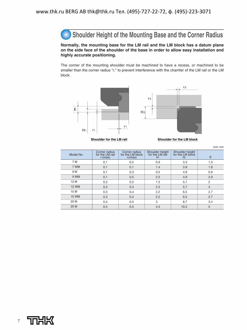
Normally, the mounting base for the LM rail and the LM block has a datum planeon the side face of the shoulder of the base in order to allow easy installation andhighly accurate positioning.
The corner of the mounting shoulder must be machined to have a recess, or machined to besmaller than the corner radius "r," to prevent interference with the chamfer of the LM rail or the LMblock.
Shoulder Height of the Mounting Base and the Corner Radius
r2
r2
r1r1
H2
H1
E
Shoulder for the LM blockShoulder for the LM rail
Model No.Corner radius for the LM rail
r1(max)
Corner radius for the LM block
r2(max)
Shoulder heightfor the LM rail
H1
Shoulder height for the LM block
H2 E
Unit: mm
7 M
7 WM
9 M
9 WM
12 M
12 WM
15 M
15 WM
20 M
25 M
0.1
0.1
0.1
0.1
0.3
0.3
0.3
0.3
0.3
0.5
0.2
0.1
0.3
0.5
0.2
0.3
0.4
0.3
0.5
0.5
0.9
1.4
0.5
2.5
1.5
2.5
2.2
2.2
3
4.5
3.3
3.8
4.9
4.9
5.7
5.7
6.5
6.5
8.7
10.5
1.3
1.8
0.9
2.9
2
3
2.7
2.7
3.4
5
www.thk.ru BERG AB [email protected] Тел. (495)-727-22-72, ф. (495)-223-3071
8
SRS OUTLINEModel SRS - Product Overview
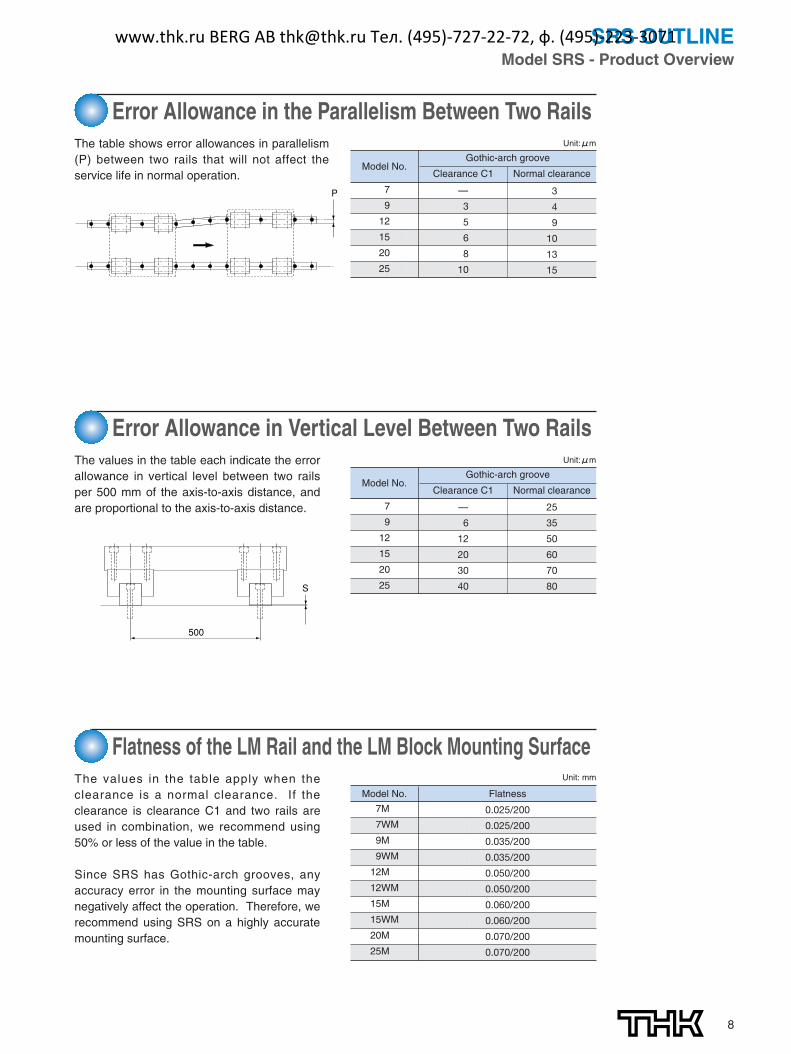
Error Allowance in the Parallelism Between Two RailsThe table shows error allowances in parallelism(P) between two rails that will not affect theservice life in normal operation.
P
The values in the table each indicate the errorallowance in vertical level between two railsper 500 mm of the axis-to-axis distance, andare proportional to the axis-to-axis distance.
Flatness of the LM Rail and the LM Block Mounting SurfaceThe values in the table apply when theclearance is a normal clearance. If theclearance is clearance C1 and two rails areused in combination, we recommend using50% or less of the value in the table.
Since SRS has Gothic-arch grooves, anyaccuracy error in the mounting surface maynegatively affect the operation. Therefore, werecommend using SRS on a highly accuratemounting surface.
500
S
Error Allowance in Vertical Level Between Two Rails
Model No.Clearance C1
Gothic-arch groove
Normal clearance
7
9
12
15
20
25
—
3
5
6
8
10
3
4
9
10
13
15
Unit:μm
Model No.Clearance C1
Gothic-arch groove
Normal clearance
7
9
12
15
20
25
—
6
12
20
30
40
25
35
50
60
70
80
Unit:μm
Model No. Flatness
7M
7WM
9M
9WM
12M
12WM
15M
15WM
20M
25M
0.025/200
0.025/200
0.035/200
0.035/200
0.050/200
0.050/200
0.060/200
0.060/200
0.070/200
0.070/200
Unit: mm
www.thk.ru BERG AB [email protected] Тел. (495)-727-22-72, ф. (495)-223-3071
9
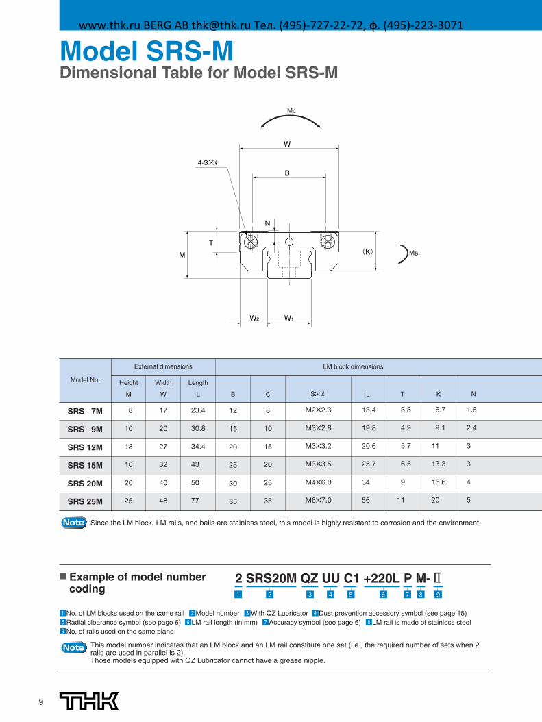
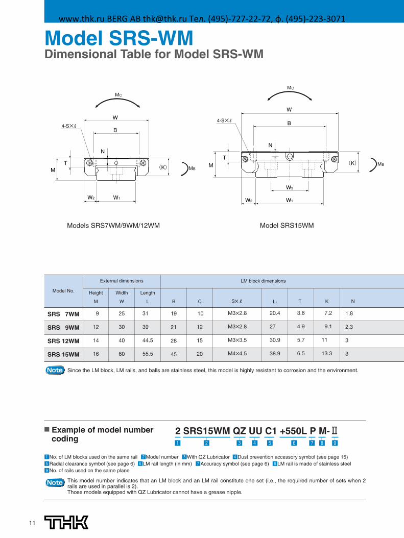
Model SRS-MDimensional Table for Model SRS-M
W1
B
(K) M
T
N
W
W2
4-S×R
MC
MB
Model No.
External dimensions LM block dimensions
Height
M
Width
W
Length
L B C S✕R L1 T K N
SRS 7M
SRS 9M
SRS 12M
SRS 15M
SRS 20M
SRS 25M
8
10
13
16
20
25
17
20
27
32
40
48
23.4
30.8
34.4
43
50
77
12
15
20
25
30
35
8
10
15
20
25
35
M2✕2.3
M3✕2.8
M3✕3.2
M3✕3.5
M4✕6.0
M6✕7.0
13.4
19.8
20.6
25.7
34
56
3.3
4.9
5.7
6.5
9
11
6.7
9.1
11
13.3
16.6
20
1.6
2.4
3
3
4
5
Note Since the LM block, LM rails, and balls are stainless steel, this model is highly resistant to corrosion and the environment.
Note This model number indicates that an LM block and an LM rail constitute one set (i.e., the required number of sets when 2rails are used in parallel is 2).Those models equipped with QZ Lubricator cannot have a grease nipple.
■ Example of model numbercoding
zNo. of LM blocks used on the same rail xModel number cWith QZ Lubricator vDust prevention accessory symbol (see page 15)bRadial clearance symbol (see page 6) nLM rail length (in mm) mAccuracy symbol (see page 6) ,LM rail is made of stainless steel.No. of rails used on the same plane
2 SRS20M QZ UU C1 +220L P M-Ⅱz , .mnbvcx
www.thk.ru BERG AB [email protected] Тел. (495)-727-22-72, ф. (495)-223-3071
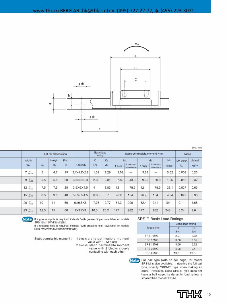
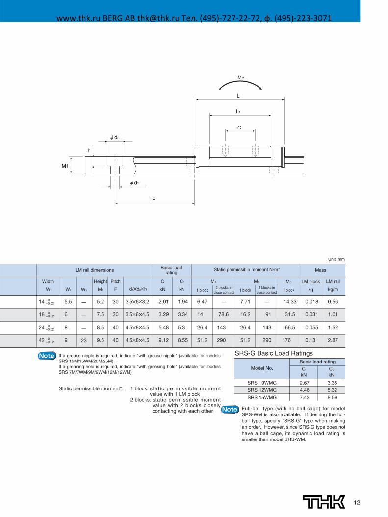
10
L
C
L1
φd2
φd1
M1
F
h
MA
Width
W1 W2
Height
M1
Pitch
F d1✕d2✕h
LM rail dimensions Basic loadrating
Static permissible moment N-m* Mass
C
kN
C0
kN
MC
1 block
LM block
kg
LM rail
kg/m
7 0–0.02
9 0–0.02
12 0–0.02
15 0–0.02
20 0–0.03
23 0–0.03
5
5.5
7.5
8.5
10
12.5
4.7
5.5
7.5
9.5
11
15
15
20
25
40
60
60
2.4✕4.2✕2.3
3.5✕6✕3.3
3.5✕6✕4.5
3.5✕6✕4.5
6✕9.5✕8
7✕11✕9
1.51
2.69
4
6.66
7.75
16.5
1.29
2.31
3.53
5.7
9.77
20.2
3.09
7.82
12
26.2
54.3
177
3.69
9.03
12
26.2
62.4
177
—
43.9
78.5
154
296
932
—
50.8
78.5
154
341
932
5.02
10.6
23.1
40.4
104
248
0.009
0.016
0.027
0.047
0.11
0.24
0.25
0.32
0.65
0.96
1.68
2.6
Unit: mm
MA MB
Note
Note
2 blocks inclose contact
2 blocks inclose contact1 block 1 block
If a grease nipple is required, indicate "with grease nipple" (available for modelsSRS 15M/15WM/20M/25M). If a greasing hole is required, indicate "with greasing hole" (available for modelsSRS 7M/7WM/9M/9WM/12M/12WM).
Static permissible moment*: 1 block: static permissible momentvalue with 1 LM block
2 blocks: static permissible momentvalue with 2 blocks closelycontacting with each other
SRS-G Basic Load Ratings
SRS 9MG
SRS 12MG
SRS 15MG
SRS 20MG
SRS 25MG
2.07
3.36
5.59
5.95
13.3
2.32
3.55
5.72
9.4
22.3
Basic load ratingModel No. C
kNC0
kN
Full-ball type (with no ball cage) for modelSRS-M is also available. If desiring the full-balltype, specify "SRS-G" type when making anorder. However, since SRS-G type does nothave a ball cage, its dynamic load rating issmaller than model SRS-M.
www.thk.ru BERG AB [email protected] Тел. (495)-727-22-72, ф. (495)-223-3071
11
B
(K) T
M
W
B
(K) MT
W
W1W2
W3
W2W1
4-S×R4-S×R
NN
Models SRS7WM/9WM/12WM Model SRS15WM
MC
MB
MC
MB
2 SRS15WM QZ UU C1 +550L P M-Ⅱ
Model No.
External dimensions LM block dimensions
Height
M
Width
W
Length
L B C S✕R L1 T K N
SRS 7WM
SRS 9WM
SRS 12WM
SRS 15WM
9
12
14
16
25
30
40
60
31
39
44.5
55.5
19
21
28
45
10
12
15
20
M3✕2.8
M3✕2.8
M3✕3.5
M4✕4.5
20.4
27
30.9
38.9
3.8
4.9
5.7
6.5
7.2
9.1
11
13.3
1.8
2.3
3
3
Note Since the LM block, LM rails, and balls are stainless steel, this model is highly resistant to corrosion and the environment.
Note This model number indicates that an LM block and an LM rail constitute one set (i.e., the required number of sets when 2rails are used in parallel is 2).Those models equipped with QZ Lubricator cannot have a grease nipple.
■ Example of model numbercoding
zNo. of LM blocks used on the same rail xModel number cWith QZ Lubricator vDust prevention accessory symbol (see page 15)bRadial clearance symbol (see page 6) nLM rail length (in mm) mAccuracy symbol (see page 6) ,LM rail is made of stainless steel.No. of rails used on the same plane
z x , .mnbvc
Model SRS-WMDimensional Table for Model SRS-WM
www.thk.ru BERG AB [email protected] Тел. (495)-727-22-72, ф. (495)-223-3071
12
L
C
L1
φd2
φd1
M1
F
h
MA
Width
W1 W2
Height
M1
Pitch
F d1✕d2✕h
LM rail dimensions Basic loadrating
Static permissible moment N-m* Mass
C
kN
C0
kN
MC
1 block
LM block
kg
LM rail
kg/m
14 0–0.02
18 0–0.02
24 0–0.02
42 0–0.02
5.5
6
8
9
W3
—
—
—
23
5.2
7.5
8.5
9.5
30
30
40
40
3.5✕6✕3.2
3.5✕6✕4.5
4.5✕8✕4.5
4.5✕8✕4.5
2.01
3.29
5.48
9.12
1.94
3.34
5.3
8.55
6.47
14
26.4
51.2
7.71
16.2
26.4
51.2
—
78.6
143
290
—
91
143
290
14.33
31.5
66.5
176
0.018
0.031
0.055
0.13
0.56
1.01
1.52
2.87
Unit: mm
MA MB
SRS 9WMG
SRS 12WMG
SRS 15WMG
2.67
4.46
7.43
3.35
5.32
8.59
Basic load ratingModel No. C
kNC0
kN
SRS-G Basic Load RatingsNote
Note
If a grease nipple is required, indicate "with grease nipple" (available for modelsSRS 15M/15WM/20M/25M). If a greasing hole is required, indicate "with greasing hole" (available for modelsSRS 7M/7WM/9M/9WM/12M/12WM)
Static permissible moment*: 1 block: static permissible momentvalue with 1 LM block
2 blocks: static permissible momentvalue with 2 blocks closelycontacting with each other Full-ball type (with no ball cage) for model
SRS-WM is also available. If desiring the full-ball type, specify "SRS-G" type when makingan order. However, since SRS-G type does nothave a ball cage, its dynamic load rating issmaller than model SRS-WM.
2 blocks inclose contact
2 blocks inclose contact1 block 1 block
www.thk.ru BERG AB [email protected] Тел. (495)-727-22-72, ф. (495)-223-3071
13
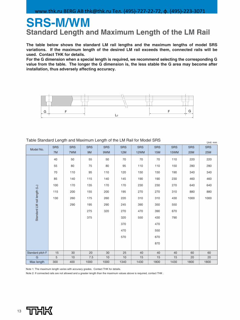
The table below shows the standard LM rail lengths and the maximum lengths of model SRSvariations. If the maximum length of the desired LM rail exceeds them, connected rails will beused. Contact THK for details.For the G dimension when a special length is required, we recommend selecting the corresponding Gvalue from the table. The longer the G dimension is, the less stable the G area may become afterinstallation, thus adversely affecting accuracy.
G F FL0
G
SRS-M/WMStandard Length and Maximum Length of the LM Rail
Note 1: The maximum length varies with accuracy grades. Contact THK for details.
Note 2: If connected rails are not allowed and a greater length than the maximum values above is required, contact THK .
Unit: mmTable Standard Length and Maximum Length of the LM Rail for Model SRS
Model No.
Standard pitch F 30
10
400
15
5
300
20 30 25 40 40
7.5 10 10 15 15
1000 1000 1340 1430 1800
60
20
1800
G
Max length
SRS
7WM
50
80
110
140
170
200
260
290
SRS
9M
55
75
95
115
135
155
175
195
275
375
SRS
9WM
50
80
110
140
170
200
260
290
320
SRS
12M
70
95
120
145
170
195
220
245
270
320
370
470
570
SRS
12WM
70
110
150
190
230
270
310
390
470
550
SRS
15M
70
110
150
190
230
270
310
350
390
430
470
550
670
870
Sta
ndar
dLM
rail
leng
th(L
0)
40 60
15 20
1430 1800
SRS
15WM
110
150
190
230
270
310
430
550
670
790
SRS
20M
220
280
340
460
640
880
1000
SRS
25M
220
280
340
460
640
880
1000
SRS
7M
40
55
70
85
100
115
130
www.thk.ru BERG AB [email protected] Тел. (495)-727-22-72, ф. (495)-223-3071

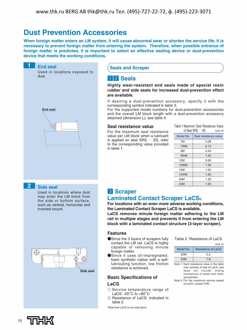
Side seal2
Laminated Contact Scraper LaCS3
End seal1
Dedicated C-cap LM rail mounting holes4
QZ Lubricator 5
Grease nipple 6
SRS OPTIONSOptionsFor model SRS, dust-prevention and lubrication accessories areavailable. Make a selection according to the application and theinstallation site.
14
Image
www.thk.ru BERG AB [email protected] Тел. (495)-727-22-72, ф. (495)-223-3071
15
zx SealsHighly wear-resistant end seals made of special resinrubber and side seals for increased dust-prevention effectare available.If desiring a dust-prevention accessory, specify it with thecorresponding symbol indicated in table 3.For the supported model numbers for dust-prevention accessoriesand the overall LM block length with a dust-prevention accessoryattached (dimension L), see table 4.
End seal
When foreign matter enters an LM system, it will cause abnormal wear or shorten the service life. It isnecessary to prevent foreign matter from entering the system. Therefore, when possible entrance offoreign matter is predicted, it is important to select an effective sealing device or dust-preventiondevice that meets the working conditions.
Dust Prevention Accessories
End sealUsed in locations exposed todust.
Seals and Scraper1
Side sealUsed in locations where dustmay enter the LM block fromthe side or bottom surface,such as vertical, horizontal andinverted mount.
Side seal
2c ScraperLaminated Contact Scraper LaCS®
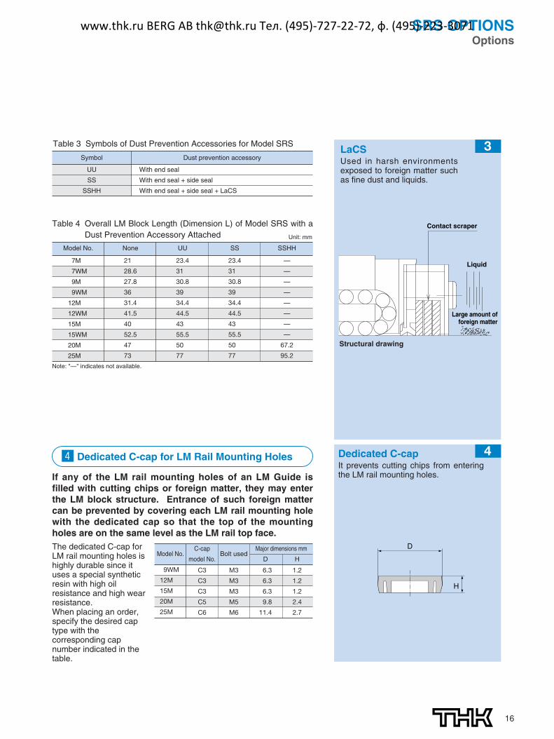
For locations with an even more adverse working conditions,the Laminated Contact Scraper LaCS is available.LaCS removes minute foreign matter adhering to the LMrail in multiple stages and prevents it from entering the LMblock with a laminated contact structure (3-layer scraper).
Features●Since the 3 layers of scrapers fully
contact the LM rail, LaCS is highlycapable of removing minuteforeign matter.●Since it uses oil-impregnated,
foam synthetic rubber with a self-lubricating function, low frictionresistance is achieved.
Basic Specifications ofLaCS1 Service temperature range of
LaCS: -20。C to +80。C2 Resistance of LaCS: indicated in
table 2*Note that LaCS is not sold alone.
Table 1 Maximum Seal Resistance Valueof Seal SRS … SS
Model No.
7M
7WM
9M
9WM
12M
12WM
15M
15WM
20M
25M
Seal resistance value
0.08
0.12
0.20
1.00
0.60
1.30
1.00
1.60
1.30
1.60
Unit: NSeal resistance valueFor the maximum seal resistancevalue per LM block when a lubricantis applied on seal SRS … SS, referto the corresponding value providedin table 1.
Table 2 Resistance of LaCS
Model No.
20M
25M
Resistance of LaCS
5.2
7.8
Unit: N
Note 1: Each resistance value in the tableonly consists of that of LaCS, anddoes not include slidingresistances of seals and otheraccessories.
Note 2: For the maximum service speedof LaCS, contact THK.
www.thk.ru BERG AB [email protected] Тел. (495)-727-22-72, ф. (495)-223-3071
16
If any of the LM rail mounting holes of an LM Guide isfilled with cutting chips or foreign matter, they may enterthe LM block structure. Entrance of such foreign mattercan be prevented by covering each LM rail mounting holewith the dedicated cap so that the top of the mountingholes are on the same level as the LM rail top face.The dedicated C-cap forLM rail mounting holes ishighly durable since ituses a special syntheticresin with high oilresistance and high wearresistance.When placing an order,specify the desired captype with thecorresponding capnumber indicated in thetable.
Model No.C-cap
model No.Bolt used
Major dimensions mm
D H
9WM
12M
15M
20M
25M
C3 M3 6.3 1.2
C3 M3 6.3 1.2
C3 M3 6.3 1.2
C5 M5 9.8 2.4
C6 M6 11.4 2.7
Model No.
7M
7WM
9M
9WM
12M
12WM
15M
15WM
20M
25M
UU SS SSHH
23.4
31.0
30.8
39.0
34.4
44.5
43.0
55.5
50.0
77.0
None
21.0
28.6
27.8
36.0
31.4
41.5
40.0
52.5
47.0
73.0
23.4
31.0
30.8
39.0
34.4
44.5
43.0
55.5
50.0
77.0
—
—
—
—
—
—
—
—
67.2
95.2
Table 4 Overall LM Block Length (Dimension L) of Model SRS with aDust Prevention Accessory Attached Unit: mm
Note: "—" indicates not available.
SRS OPTIONSOptions
Table 3 Symbols of Dust Prevention Accessories for Model SRS
Liquid
Contact scraper
Large amount offoreign matter
Structural drawing
v Dedicated C-cap for LM Rail Mounting Holes
LaCSUsed in harsh environmentsexposed to foreign matter suchas fine dust and liquids.
3
4
D
H
Dedicated C-cap It prevents cutting chips from enteringthe LM rail mounting holes.
Symbol
UU
SS
SSHH
Dust prevention accessory
With end seal
With end seal + side seal
With end seal + side seal + LaCS
www.thk.ru BERG AB [email protected] Тел. (495)-727-22-72, ф. (495)-223-3071
17
Model No.
7M
7WM
9M
9WM
12M
12WM
15M
15WM
20M
25M
QZUU QZSS QZSSHH
33.4
41.0
40.8
49.0
44.4
54.5
55.0
67.5
66.0
97.0
33.4
41.0
40.8
49.0
44.4
54.5
55.0
67.5
66.0
97.0
—
—
—
—
—
—
—
—
83.2
115.2
Table 2 Overall LM Block Length (Dimension L) of Model SRS with the QZLubricator Attached
Note: "—" indicates not available.
Table 1 Parts Symbols for Model SRS with the QZ Lubricator Attached
Symbol
QZUU
QZSS
QZSSHH
Dust prevention accessories for the LM Guide with the QZ Lubricator attached
With end seal + QZ Lubricator
With end seal + side seal + QZ Lubricator
With end seal + side seal + LaCS + QZ Lubricator
Lubrication Accessories
b QZ LubricatorTM
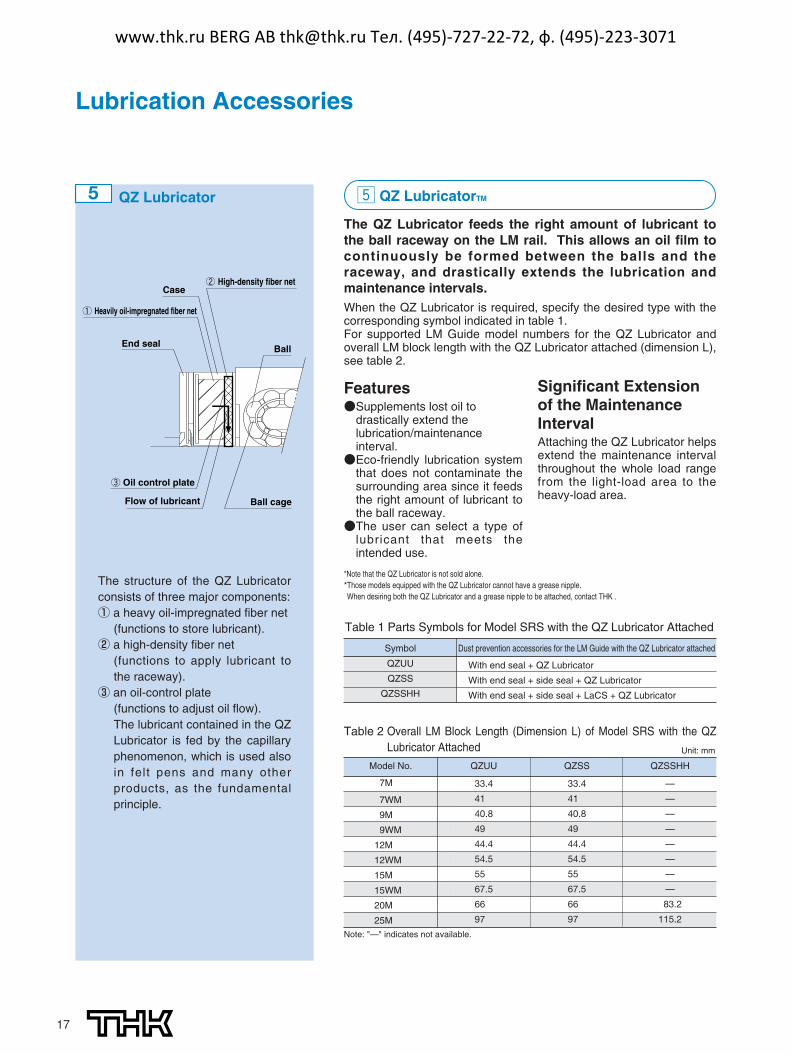
The QZ Lubricator feeds the right amount of lubricant tothe ball raceway on the LM rail. This allows an oil film tocontinuously be formed between the balls and theraceway, and drastically extends the lubrication andmaintenance intervals.When the QZ Lubricator is required, specify the desired type with thecorresponding symbol indicated in table 1.For supported LM Guide model numbers for the QZ Lubricator andoverall LM block length with the QZ Lubricator attached (dimension L),see table 2.
End seal
Flow of lubricant
③ Oil control plate
Ball cage
Ball
Case② High-density fiber net
① Heavily oil-impregnated fiber net
Features●Supplements lost oil to
drastically extend thelubrication/maintenanceinterval.●Eco-friendly lubrication system
that does not contaminate thesurrounding area since it feedsthe right amount of lubricant tothe ball raceway.●The user can select a type of
lubricant that meets theintended use.
Significant Extensionof the MaintenanceIntervalAttaching the QZ Lubricator helpsextend the maintenance intervalthroughout the whole load rangefrom the light-load area to theheavy-load area.
5 QZ Lubricator
The structure of the QZ Lubricatorconsists of three major components:① a heavy oil-impregnated fiber net
(functions to store lubricant).② a high-density fiber net
(functions to apply lubricant tothe raceway).
③ an oil-control plate(functions to adjust oil flow).The lubricant contained in the QZLubricator is fed by the capillaryphenomenon, which is used alsoin felt pens and many otherproducts, as the fundamentalprinciple.
Unit: mm
*Note that the QZ Lubricator is not sold alone.*Those models equipped with the QZ Lubricator cannot have a grease nipple. When desiring both the QZ Lubricator and a grease nipple to be attached, contact THK .
www.thk.ru BERG AB [email protected] Тел. (495)-727-22-72, ф. (495)-223-3071
18
SRS OPTIONSOptions
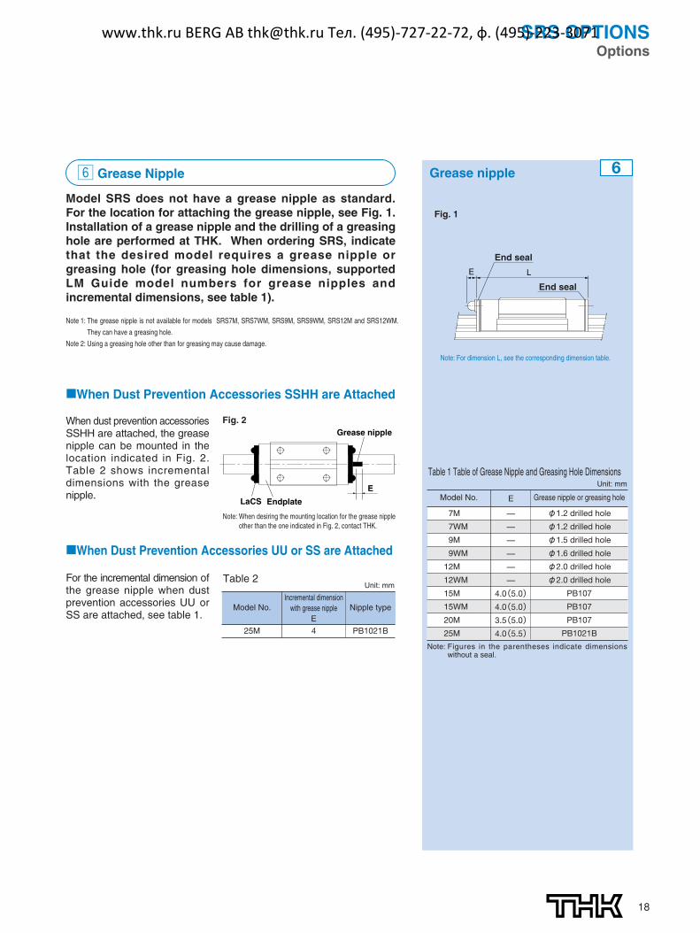
n Grease Nipple
Model SRS does not have a grease nipple as standard.For the location for attaching the grease nipple, see Fig. 1.Installation of a grease nipple and the drilling of a greasinghole are performed at THK. When ordering SRS, indicatethat the desired model requires a grease nipple orgreasing hole (for greasing hole dimensions, supportedLM Guide model numbers for grease nipples andincremental dimensions, see table 1).
■When Dust Prevention Accessories SSHH are Attached
When dust prevention accessoriesSSHH are attached, the greasenipple can be mounted in thelocation indicated in Fig. 2.Table 2 shows incrementaldimensions with the greasenipple.
■When Dust Prevention Accessories UU or SS are Attached
For the incremental dimension ofthe grease nipple when dustprevention accessories UU orSS are attached, see table 1.
Grease nipple
LaCS Endplate
E
Fig. 2
6Grease nipple
E L
End seal
End seal
Fig. 1
Note: For dimension L, see the corresponding dimension table.
Table 1 Table of Grease Nipple and Greasing Hole Dimensions
Model No.
7M
7WM
9M
9WM
12M
12WM
15M
15WM
20M
25M
Grease nipple or greasing hole
φ1.2 drilled hole
φ1.2 drilled hole
φ1.5 drilled hole
φ1.6 drilled hole
φ2.0 drilled hole
φ2.0 drilled hole
PB107
PB107
PB107
PB1021B
E
—
—
—
—
—
—
4.0(5.0)
4.0(5.0)
3.5(5.0)
4.0(5.5)
Unit: mm
Note: Figures in the parentheses indicate dimensionswithout a seal.
Note 1: The grease nipple is not available for models SRS7M, SRS7WM, SRS9M, SRS9WM, SRS12M and SRS12WM.
They can have a greasing hole.
Note 2: Using a greasing hole other than for greasing may cause damage.
Note: When desiring the mounting location for the grease nippleother than the one indicated in Fig. 2, contact THK.
25M
Model No.Incremental dimension
with grease nipple E
4
Nipple type
PB1021B
Unit: mmTable 2
www.thk.ru BERG AB [email protected] Тел. (495)-727-22-72, ф. (495)-223-3071

Caged Ball LM Guide Model SRS
©THK CO., LTD. 20050303 Printed in Japan
Precautions on use� Handling
� Disassembling components may cause dust to enter the system or degrade mounting accuracy of parts. Do not disassemble theproduct.
� Tilting an LM block or LM rail may cause them to fall by their own weight.� Dropping or hitting the LM Guide may damage it. Giving an impact to the LM Guide could also cause damage to its function even if
the guide looks intact.� Lubrication
� Thoroughly remove anti-corrosion oil and feed lubricant before using the product.� Do not mix lubricants of different physical properties.� In locations exposed to constant vibrations or in special environments such as clean rooms, vacuum and low/high temperature,
normal lubricants may not be used. Contact THK for details.� When planning to use a special lubricant, contact THK before using it.� When adopting oil lubrication, the lubricant may not be distributed throughout the LM system depending on the mounting orientation
of the system. Contact THK for details.� Lubrication interval varies according to the service conditions. Contact THK for details.
� Precautions on Use� Entrance of foreign matter may cause damage to the ball circulating path or functional loss. Prevent foreign matter, such as dust or
cutting chips, from entering the system.� When planning to use the LM system in an environment where coolant penetrates the LM block, it may cause trouble to product
functions depending on the type of coolant. Contact THK for details.� Do not use the LM system at temperature of 80℃ or higher. When desiring to use the system at temperature of 80℃ or higher,
contact THK in advance.� If foreign matter adheres to the LM system, replenish the lubricant after cleaning the product. For available types of detergent,
contact THK .� When using the LM Guide with an inverted mount, breakage of the endplate due to an accident or the like may cause balls to fall
out and the LM block to come off from the LM rail and fall. In these cases, take preventive measures such as adding a safetymechanism for preventing such falls.
� When using the LM system in locations exposed to constant vibrations or in special environments such as clean rooms, vacuumand low/high temperature, contact THK in advance.
� When removing the LM block from the LM rail and then replacing the block, an LM block mounting/removing jig that facilitates suchinstallation is available. Contact THK for details.
� Storage� When storing the LM Guide, enclose it in a package designated by THK and store it in a horizontal orientation while avoiding high
temperature, low temperature and high humidity.
● “LM Guide,” “Ball Cage,” “ ,” and “QZ” are registered trademarks of THK CO., LTD.● The photo may differ slightly in appearance from the actual product.● The appearance and specifications of the product are subject to change without notice. Contact THK before placing an order.● Although great care has been taken in the production of this catalog, THK will not take any responsibility for damage resulting from typographical errors or omissions.● For the export of our products or technologies and for the sale for exports, THK in principle complies with the foreign exchange law and the Foreign Exchange
and Foreign Trade Control Law as well as other relevant laws.For export of THK products as single items, contact THK in advance. All rights reserved
HEAD OFFICE 3-11-6, NISHI-GOTANDA, SHINAGAWA-KU, TOKYO 141-8503 JAPAN ASIA PACIFIC SALES DEPARTMENT PHONE:(03)5434-0351 FAX:(03)5434-0353
NORTH AMERICACHICAGOPHONE:(847)310-1111 FAX:(847)310-1182
NEW JERSEYPHONE:(201)529-1950 FAX:(201)529-1962
ATLANTAPHONE:(770)840-7990 FAX:(770)840-7897
LOS ANGELESPHONE:(714)891-6752 FAX:(714)894-9315
SAN FRANCISCOPHONE:(925)455-8948 FAX:(925)455-8965
BOSTONPHONE:(781)575-1151 FAX:(781)575-9295
DETROITPHONE:(248)858-9330 FAX:(248)858-9455
TORONTOPHONE:(905)712-2922 FAX:(905)712-2925
BRASIL (SÃO PAULO)PHONE:(011)3767-0100 FAX:(011)3767-0101
EUROPEDÜSSELDORF
PHONE:0049-(0)2102-7425-0 FAX:0049-(0)2102-7425-299STUTTGART
PHONE:0049-(0)7150-9199-0 FAX:0049-(0)7150-9199-888MÜNCHEN
PHONE:0049-(0)89-370616-0 FAX:0049-(0)89-370616-26U.K.
PHONE:0044-(0)1908-303050 FAX:0044-(0)1908-303070MILANO
PHONE:0039-039-2842079 FAX:0039-039-2842527BOLOGNA
PHONE:0039-051-6412211 FAX:0039-051-6412230SWEDEN
PHONE:0046-(0)8-4457630 FAX:0046-(0)8-4457639AUSTRIA
PHONE:0043-(0)7229-51400 FAX:0043-(0)7229-51400-79SPAIN
PHONE:0034-93-652-5740 FAX:0034-93-652-5746THK FRANCE S. A. S.
PHONE:0033-(0)4-37491400 FAX:0033-(0)4-37491401SOUTH AFRICA
PHONE:0027-(0)44-2720020 FAX:0027-(0)44-2720020
CHINATHK SHANGHAI CO.,LTD.PHONE:(21)6334-5131 FAX:(21)6334-5137
BEI JINGPHONE:(10)6590-3259 FAX:(10)6590-3557
THK SHOUZAN CO.,LTD.PHONE:2376-1091 FAX:2376-0749
TAIWANTAIPEIPHONE:(02)2888-3818 FAX:(02)2888-3819
TAICHUNGPHONE:(04)2359-1505 FAX:(04)2359-1506
SOUTHERNPHONE:(06)289-7668 FAX:(06)289-7669
KOREA (SEOUL)PHONE:(02)3468-4351 FAX:(02)3468-4353
MALAYSIA (KUALA LUMPUR)PHONE:(03)9287-1137 FAX:(03)9287-8071
INDIA (BANGALORE)PHONE:(080)2330-1524FAX:(080)2330-1524
www.thk.ru BERG AB [email protected] Тел. (495)-727-22-72, ф. (495)-223-3071