Embed Size (px)
Citation preview
TECHNICAL SPECIFICATION
SPÉCIFICATION TECHNIQUE
TECHNISCHE SPEZIFIKATION
CEN/TS 54-14
July 2004
ICS 13.220.20
English version
Fire detection and fire alarm systems - Part 14: Guidelines for planning, design, installation, commissioning, use and
maintenance
Systèmes de détection et d'alarme incendie - Partie 14: Guide d'application pour la planification, la conception,
l'installation, la mise en service, l'utilisation et la maintenance
Brandmeldeanlagen - Teil 14: Leitfaden für Planung, Projektierung, Montage, Inbetriebnahme, Betrieb und
Instandhaltung
This Technical Specification (CEN/TS) was approved by CEN on 29 April 2004 for provisional application. The period of validity of this CEN/TS is limited initially to three years. After two years the members of CEN will be requested to submit their comments, particularly on the question whether the CEN/TS can be converted into a European Standard. CEN members are required to announce the existence of this CEN/TS in the same way as for an EN and to make the CEN/TS available promptly at national level in an appropriate form. It is permissible to keep conflicting national standards in force (in parallel to the CEN/TS) until the final decision about the possible conversion of the CEN/TS into an EN is reached. CEN members are the national standards bodies of Austria, Belgium, Cyprus, Czech Republic, Denmark, Estonia, Finland, France, Germany, Greece, Hungary, Iceland, Ireland, Italy, Latvia, Lithuania, Luxembourg, Malta, Netherlands, Norway, Poland, Portugal, Slovakia, Slovenia, Spain, Sweden, Switzerland and United Kingdom.
EUROPEAN COMMITTEE FOR STANDARDIZATION C O M I T É E U R O P É E N D E N O R M A LI S A T I O N EUR OP ÄIS C HES KOM ITEE FÜR NOR M UNG
Management Centre: rue de Stassart, 36 B-1050 Brussels
© 2004 CEN All rights of exploitation in any form and by any means reserved worldwide for CEN national Members.
Ref. No. CEN/TS 54-14:2004: E

CEN/TS 54-14:2004 (E)
2
Contents Page
Foreword......................................................................................................................................................................6 Introduction.................................................................................................................................................................7 1 Scope ..............................................................................................................................................................8 2 Normative references ....................................................................................................................................8 3 Terms and definitions ...................................................................................................................................8 4 General..........................................................................................................................................................13 4.1 Guideline usage ...........................................................................................................................................13 4.2 Guideline format ..........................................................................................................................................13 4.3 Safety requirements ....................................................................................................................................14 4.4 False alarms .................................................................................................................................................14 4.5 Warranties and guarantees.........................................................................................................................14 4.6 Documentation.............................................................................................................................................15 4.7 Responsibility ..............................................................................................................................................15 4.8 Qualifications ...............................................................................................................................................15 5 Assessment of needs..................................................................................................................................15 5.1 Purpose.........................................................................................................................................................15 5.2 Consultation.................................................................................................................................................15 5.3 Parts of the building needing cover ..........................................................................................................16 5.3.1 Extent of cover.............................................................................................................................................16 5.3.2 Description of extent ...................................................................................................................................17 5.3.3 Total cover....................................................................................................................................................17 5.3.4 Compartment cover.....................................................................................................................................17 5.3.5 Escape route cover......................................................................................................................................17 5.3.6 Local cover ...................................................................................................................................................17 5.3.7 Equipment cover..........................................................................................................................................18 5.3.8 Areas not needing cover.............................................................................................................................18 5.4 Fire brigade attendance ..............................................................................................................................18 5.4.1 Communications..........................................................................................................................................18 5.4.2 Attendance time...........................................................................................................................................18 5.5 Fire alarm response strategy .....................................................................................................................18 5.6 Documentation.............................................................................................................................................19 5.7 Responsibility ..............................................................................................................................................19 5.8 Qualifications ...............................................................................................................................................19 6 Planning and design....................................................................................................................................20 6.1 Devices connected to the system..............................................................................................................20 6.1.1 Components.................................................................................................................................................20 6.2 System design .............................................................................................................................................20 6.2.1 Compatibility ................................................................................................................................................20 6.2.2 Fault effects..................................................................................................................................................20 6.2.3 Hazardous atmospheres .............................................................................................................................20 6.2.4 False alarms .................................................................................................................................................20 6.2.5 Other fire protection systems ....................................................................................................................20 6.2.6 Special risks.................................................................................................................................................21 6.3 Zones ............................................................................................................................................................21 6.3.1 General..........................................................................................................................................................21 6.3.2 Detection zones ...........................................................................................................................................21 6.3.3 Alarm zones .................................................................................................................................................21 6.4 Selection of detectors and manual call points .........................................................................................21
CEN/TS 54-14:2004(E)
3
6.4.1 Detectors - General......................................................................................................................................21 6.4.2 Smoke detectors..........................................................................................................................................22 6.4.3 Heat detectors..............................................................................................................................................23 6.4.4 Flame detectors ...........................................................................................................................................23 6.4.5 Manual call points........................................................................................................................................24 6.5 Siting and spacing of detectors and manual call points .........................................................................24 6.5.1 General..........................................................................................................................................................24 6.5.2 Heat and smoke detectors ..........................................................................................................................24 6.5.3 Flame detectors ...........................................................................................................................................24 6.5.4 Manual call points........................................................................................................................................25 6.5.5 Identification ................................................................................................................................................25 6.6 Alarm systems and devices .......................................................................................................................25 6.6.1 General..........................................................................................................................................................25 6.6.2 Sound signals ..............................................................................................................................................25 6.6.3 Visual fire alarm devices.............................................................................................................................26 6.7 Control and indication.................................................................................................................................26 6.7.1 Location of control and indicating equipment .........................................................................................26 6.7.2 Repeat indications.......................................................................................................................................26 6.7.3 Repeat controls............................................................................................................................................26 6.7.4 Alarm location aids......................................................................................................................................27 6.7.5 Fire brigade panel........................................................................................................................................27 6.8 Power supplies ............................................................................................................................................27 6.8.1 Power supply equipment ............................................................................................................................27 6.8.2 Main power source ......................................................................................................................................27 6.8.3 Standby supply ............................................................................................................................................27 6.9 Signals to a fire alarm receiving station....................................................................................................28 6.10 Other equipment or systems......................................................................................................................28 6.11 Cables and interconnections......................................................................................................................29 6.11.1 Cable types...................................................................................................................................................29 6.11.2 Protection against fire.................................................................................................................................29 6.11.3 Protection against mechanical damage ....................................................................................................29 6.12 Protection against electromagnetic interference.....................................................................................29 6.13 Documentation.............................................................................................................................................29 6.14 Responsibility ..............................................................................................................................................30 6.15 Qualifications ...............................................................................................................................................30 7 Installation ....................................................................................................................................................30 7.1 General..........................................................................................................................................................30 7.2 Siting and accommodation of equipment .................................................................................................30 7.2.1 Siting .............................................................................................................................................................30 7.2.2 Hazardous areas ..........................................................................................................................................30 7.3 Cable installation .........................................................................................................................................30 7.3.1 General..........................................................................................................................................................30 7.3.2 Cable ducts, channels and trunking..........................................................................................................30 7.3.3 Cable routing................................................................................................................................................30 7.3.4 Precautions against spread of fire.............................................................................................................31 7.3.5 Cable joints and terminations ....................................................................................................................31 7.4 Radioactivity ................................................................................................................................................31 7.5 Documentation.............................................................................................................................................31 7.6 Responsibility ..............................................................................................................................................31 7.7 Qualifications ...............................................................................................................................................31 8 Commissioning and verification ................................................................................................................32 8.1 General..........................................................................................................................................................32 8.2 Commissioning............................................................................................................................................32 8.3 Verification ...................................................................................................................................................32 8.4 Documentation.............................................................................................................................................32 8.5 Responsibility ..............................................................................................................................................33 8.6 Qualifications ...............................................................................................................................................33 9 Third party approval ....................................................................................................................................33
CEN/TS 54-14:2004 (E)
4
9.1 General..........................................................................................................................................................33 9.2 Approval by authorities and others ...........................................................................................................33 9.2.1 Authorities having jurisdiction...................................................................................................................33 9.2.2 Insurance organisations .............................................................................................................................33 9.2.3 Approval by more than one body ..............................................................................................................33 9.3 Approval procedures...................................................................................................................................33 9.3.1 General..........................................................................................................................................................33 9.3.2 Inspection and testing.................................................................................................................................34 9.3.3 Testing of operation ....................................................................................................................................34 9.3.4 Special tests (on-site testing).....................................................................................................................34 9.3.5 Documentation.............................................................................................................................................34 9.4 Periodic inspection by an approving body...............................................................................................34 9.4.1 General..........................................................................................................................................................34 9.4.2 Documentation.............................................................................................................................................34 9.5 Qualifications ...............................................................................................................................................35 10 Use of the system ........................................................................................................................................35 10.1 Responsibility ..............................................................................................................................................35 10.2 Documentation.............................................................................................................................................36 11 Maintenance .................................................................................................................................................36 11.1 General..........................................................................................................................................................36 11.2 Inspection and servicing.............................................................................................................................36 11.2.1 Maintenance routine....................................................................................................................................36 11.2.2 Prevention of false alarms during routine testing ...................................................................................36 11.2.3 Prevention of unwanted activation during routine testing......................................................................37 11.3 Special servicing .........................................................................................................................................37 11.4 Repair and modification..............................................................................................................................37 11.5 Spares ...........................................................................................................................................................37 11.6 Documentation.............................................................................................................................................38 11.7 Responsibility ..............................................................................................................................................38 11.8 Qualifications ...............................................................................................................................................38 12 Modification or extension of an installed system ....................................................................................38 12.1 General..........................................................................................................................................................38 12.2 Third party approval ....................................................................................................................................38 12.3 Extent of compliance...................................................................................................................................38 13 Operation of other fire protection systems...............................................................................................39 13.1 General..........................................................................................................................................................39 13.2 Responsibility ..............................................................................................................................................39 14 Applications in special risks ......................................................................................................................39 14.1 General..........................................................................................................................................................39 14.2 Electronic data processing areas ..............................................................................................................40 14.3 High-rack warehouses ................................................................................................................................40 14.4 Atrium buildings ..........................................................................................................................................40 14.5 Hazardous areas ..........................................................................................................................................41 14.6 Outdoor areas ..............................................................................................................................................41 14.7 Responsibility ..............................................................................................................................................41 15 Integrated systems ......................................................................................................................................41 16 Hierarchical systems...................................................................................................................................41 Annex A (informative) Specific recommendations ..............................................................................................43 A.1 Scope ............................................................................................................................................................43 A.2 Normative references ..................................................................................................................................43 A.3 Definitions ....................................................................................................................................................43 A.4 General..........................................................................................................................................................43 A.4.1 Usage of the guidelines ..............................................................................................................................43 A.5 Assessment of needs..................................................................................................................................43 A.5.1 Purpose.........................................................................................................................................................43
CEN/TS 54-14:2004(E)
5
A.5.2 Consultation.................................................................................................................................................43 A.5.3 Part of the building needing cover ............................................................................................................43 A.6 Planning and design....................................................................................................................................45 A.6.1 System design .............................................................................................................................................45 A.6.2 Zones ............................................................................................................................................................46 A.6.3 Selection of detectors and manual call points .........................................................................................46 A.6.4 Siting and spacing of detectors and manual call points .........................................................................47 A.6.5 Alarm systems and devices .......................................................................................................................51 A.6.6 Control and indication.................................................................................................................................53 A.6.7 Power supplies ............................................................................................................................................53 A.6.8 Signals to a fire alarm receiving station....................................................................................................54 A.6.9 Other equipment or systems......................................................................................................................54 A.6.10 Cables and interconnections......................................................................................................................54 A.7 Installation ....................................................................................................................................................55 A.7.1 General..........................................................................................................................................................55 A.7.2 Siting and accommodation of equipment .................................................................................................55 A.7.3 Cable installation .........................................................................................................................................55 A.8 Commissioning and verification ................................................................................................................56 A.9 Third party approval ....................................................................................................................................56 A.10 Use of the system ........................................................................................................................................56 A.11 Maintenance .................................................................................................................................................57 A.11.1 General..........................................................................................................................................................57 A.11.2 Inspection and servicing.............................................................................................................................57 A.11.3 Special servicing .........................................................................................................................................58 A.11.4 Repair and modification..............................................................................................................................58 A.11.5 Spares ...........................................................................................................................................................59 A.11.6 Documentation.............................................................................................................................................59 A.12 Modification or extension of an installed system ....................................................................................59 A.13 Operation of other fire protection systems...............................................................................................59 A.14 Application in special risks ........................................................................................................................59 A.15 Integrated systems ......................................................................................................................................59 A.16 Hierarchical systems...................................................................................................................................59 Annex B (informative) False alarms ......................................................................................................................60 B.1 Prevention of false alarms..........................................................................................................................60 B.2 Smoke detectors..........................................................................................................................................60 B.3 Heat detectors..............................................................................................................................................61 B.4 Flame detectors ...........................................................................................................................................61 B.5 Multi-phenomena systems..........................................................................................................................61 B.6 Pre-alarm warnings .....................................................................................................................................61 B.7 Activity related systems..............................................................................................................................62 B.8 Pre-transmission confirmation ..................................................................................................................63 B.9 Investigation of false alarms ......................................................................................................................64 Annex C (informative) Model documents..............................................................................................................65 Annex D (informative) Model list of fire loadings for different cable types.......................................................71 Bibliography..............................................................................................................................................................76

CEN/TS 54-14:2004 (E)
6
Foreword
This document (CEN/TS 54-14:2004) has been prepared by Technical Committee CEN/TC 72 “Fire detection and fire alarm systems”, the secretariat of which is held by BSI.
This document has been prepared in cooperation with the CEA (Comité Européen des Assurances) and with EURALARM (Association of European Manufacturers of Fire and Intruder Alarm Systems).
This document is part of the EN 54 series of standards.
According to the CEN/CENELEC Internal Regulations, the following countries are bound to implement this European Standard: Austria, Belgium, Czech Republic, Denmark, Finland, France, Germany, Greece, Hungary, Iceland, Ireland, Italy, Luxembourg, Malta, Netherlands, Norway, Portugal, Slovakia, Spain, Sweden, Switzerland and United Kingdom.
CEN/TS 54-14:2004(E)
7
Introduction
Guidelines covering fire detection and fire alarm systems are published by many different organisations within Europe. The intention of this document is to draw together these many different documents, so as to provide a unified set of guidelines which can give a reasonable Technical Specification of planning, design, installation, commissioning, use and maintenance for fire detection and fire alarm systems throughout Europe.
It is not intended that these guidelines should override existing documents. It is expected for a considerable (and as yet unspecified) period that these guidelines will coexist with the other documents. But it is hoped that the availability of a common set of guidelines will assist in the gradual harmonisation of practice and standards of fire detection and fire alarm systems throughout Europe.
The recommendations within these guidelines are not of themselves mandatory, and have no direct power. They can however be made mandatory by being specified within another document which is itself mandatory. For example, an authority having power under local or national legislation can require compliance with the guidelines, or a contract between a purchaser and a supplier can specify compliance (which may then become mandatory for that system under contract law). The detailed methods by which recommendations become mandatory are not specified within this document, and are a matter for whichever organisation has the necessary authorities.
The main principles on which the guidelines are based are given in the body of the standard. Detailed recommendations by which these principles may be satisfied are given in Annexes.
CEN/TS 54-14:2004 (E)
8
1 Scope
This document provides guidelines for the application of automatic fire detection and fire alarm systems in and around buildings. The Technical Specification covers planning, design, installation, commissioning, use and maintenance of the systems.
The guidelines cover systems intended for the protection of life and/or the protection of property.
The guidelines cover systems with at least one fire detector. The systems may be capable of providing signals to initiate, in the event of a fire, the operation of ancillary equipment (such as fixed fire extinguishing systems) and other precautions and actions (such as machinery shutdown), but the guidelines do not cover the ancillary services themselves.
The guidelines do not cover systems combining fire alarm functions with other non-fire related functions.
The guidelines do not recommend whether or not an automatic fire detection and/or fire alarm system should be installed in any given premises.
It has been assumed in the drafting of this Part of EN 54 that the execution of its provisions will been trusted to appropriately competent persons. However, guidance is also given to other persons purchasing or using a fire detection or fire alarm system.
2 Normative references
The following referenced document is indispensable for the application of this document. For dated references, only the edition cited applies. For undated references, the latest edition of the referenced document (including any amendments) applies.
EN 54-1:1996, Fire detection and fire alarm systems – Part 1: Introduction
3 Terms and definitions
For the purposes of this document, the terms and definitions given in EN 54-1:1996 and the following apply.
3.1 acceptance decision that the installed system meets the requirements of a previously agreed specification
3.2 alarm load maximum power (normally electrical) that might be required under the fire condition
3.3 ancillary equipment equipment which can initiate or be initiated by the fire detection and alarm system
3.4 approval agreement by a third party that the installed system satisfies the requirements of the third party
CEN/TS 54-14:2004(E)
9
3.5 approval body body accepted by an authority having jurisdiction or other competent organisation as having the expertise necessary to assess the compliance of the installed system with this standard
3.6 authority having jurisdiction body having powers provided under local, regional, national or European legislation
3.7 beam detector more commonly used term for 'smoke detector - line detector using a transmitted light beam' (see EN 54-12)
3.8 circuit interconnected assembly of cables, components and elements, terminated at the control and indicating equipment in such a way that its only connection to other parts of the fire detection and alarm system is through the control and indicating equipment and controlled by the control and indicating equipment
NOTE 1 A circuit may have more than one link to the control and indicating equipment (as in a loop circuit, connected to the control and indicating equipment at both ends).
NOTE 2 If two or more cables are directly linked together inside the control and indicating equipment, without the possibility of control by the link, then they are part of the same circuit.
3.9 commissioning process by which it is verified that the installed system meets the defined requirements
3.10 commissioning engineer person who carries out the process of commissioning
3.11 competent person person who, in relation to the work undertaken, has the necessary knowledge, skill and experience to complete the work satisfactorily and without danger or injury to any person
3.12 component device which is defined as a component type I or component type II in EN 54-13
3.13 designer person or organisation taking responsibility for the work outlined in Clause 6
3.14 false alarm fire alarm caused by reasons other than fire
NOTE Information on false alarms is given in Annex B.
3.15 fault failure within the system in such a way as to jeopardise the correct functioning of the system

CEN/TS 54-14:2004 (E)
10
3.16 fault signal signal intended to indicate the occurrence of a fault
3.17 fault warning fault signal perceptible to a person
3.18 fire pyrolysis or combustion needing investigation and/or corrective action in order to prevent danger to life or property
3.19 fire alarm visual, audible or tactile indication of fire
3.20 fire alarm response strategy pre-planned procedures which are expected to be followed when a fire alarm occurs
3.21 fire attendance time between alarm and arrival of trained fire fighters 3.22 fire compartment compartment whose boundary components are required by regulations to have a defined fire resistance
3.23 fire signal signal intended to indicate the occurrence of a fire
3.24 hierarchical system networked system in which one control and indicating equipment is designated as the main control and indicating equipment, and in which the main control and indicating equipment is able to:
a) receive signals from and/or transmit signals to subsidiary control and indicating equipment;
b) indicate the status of the subsidiary control and indicating equipment.
3.25 inspection routine processes by which the system, its functioning and its indications are manually checked at pre-determined intervals
3.26 installation work of fixing and interconnecting the components and elements of a system. Installation may be carried out by one or more parties (also see 8.2)
3.27 installed system system after installation and commissioning has been completed

CEN/TS 54-14:2004(E)
11
3.28 installer person or organisation having responsibility for all or part of the process of installation
3.29 integrated system system in which the fire detection and alarm functions are integrated with other non-fire functions
3.30 maintenance work of inspection, servicing and repair necessary in order to maintain the efficient operation of the installed system
3.31 mimic diagram diagrammatic representation of the building, carrying active indications which are directly related to the building layout
3.32 national document document, published by a national standards body, giving national recommendations or requirements for installed systems, but not having general application within all CEN countries
3.33 networked system fire detection and fire alarm system in which several control and indicating equipment are interconnected and able to exchange information
3.34 pre-warning warning given when the signal from a sensor exceeds the normal level but has not yet reached the fire level
3.35 purchaser person or organisation taking primary responsibility for payment for the installed system
3.36 qualified satisfying any relevant national, regional or local standards for competence
3.37 quiescent condition condition of the installed system when it is supplied by power from its main power source, and has no indicated fire alarms, fault warnings or disablements
3.38 repair non-routine work necessary to restore the efficient operation of the installed system
3.39 repeat indicating panel panel which replicates all or some of the indications of the control and indicating equipment,
3.40 search distance distance that a person has to travel within the affected zone in order to visually determine the position of the fire
CEN/TS 54-14:2004 (E)
12
3.41 servicing routine processes of work on the system (including cleaning, re-alignment, adjustment and replacement) carried out at pre-determined intervals
3.42 standby load power taken by the system under failure of the main power source but otherwise quiescent condition
3.43 supplier organisation from which all or part of the hardware and/or software for the installed system is purchased
NOTE If all the hardware and/or software for an installed system is purchased from a single organisation, then that organisation is called the system supplier.
3.44 third party body or organisation other than the installer, supplier or customer
3.45 user person or organisation having control of the building (or part of the building) in which the fire detection and alarm system is installed
3.46 verification process by which the installer or other contractor satisfies the customer that the installed system meets the defined requirements
3.47 zone geographical sub-division of the protected premises in which a function may be carried out separately from any other sub-division
NOTE 1 The function may, for instance, be: - the indication of the occurrence of a fire (detection zone); - the giving of a fire alarm (alarm zone).
NOTE 2 Zoning for different functions need not be identical.
3.48 zone card portable zone map, covering one or more individual zones
3.49 zone map diagram showing the geographic boundaries of zones and, if necessary access routes to zones
CEN/TS 54-14:2004(E)
13
4 General
4.1 Guideline usage
These guidelines provide recommendations for planning, design, installation, commissioning, use and maintenance of fire detection and fire alarm systems. In this form they are not mandatory, but are believed to provide a suitable basis for the provision and usage of good systems. Since the recommendations are not mandatory, they specify what “should” be done, rather than giving requirements on what “shall” be done.
Also see A.4.1.
4.2 Guideline format
It is appreciated that the guidelines cannot cover every possible case that might arise. For this reason, departure from the recommendations are possible, provided that they have been discussed and agreed between all interested parties (see 5.2).
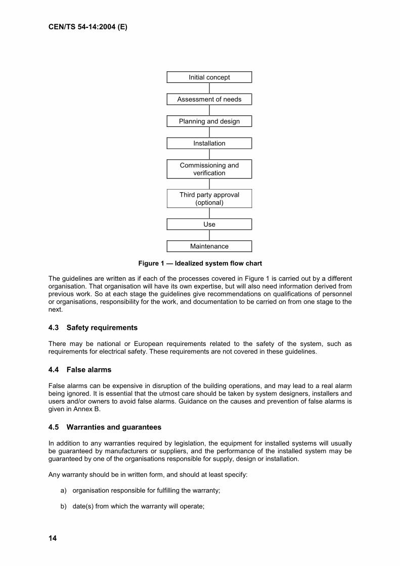
These guidelines have been drawn up as if the provision and use of an installed system will follow the pattern shown in Figure 1.
It is assumed that the first step in the design process is to assess the needs of the building for fire detection and fire alarm (see Clause 5). This may include an assessment of:
a) whether part or all of the building is to be protected;
b) the type of system to be installed;
c) the interaction of the system with other fire protection measures.
The second step is planning and design of the system (see Clause 6). This may include:
d) the selection of detector type and siting for the various parts of the building;
e) subdivision of the building into detection and/or alarm zones;
f) provision for control of the system and for the display of its indications;
g) the provision of power supplies.
The third step is the process of mounting and interconnecting the equipment (see Clause 7).
The fourth step is the commissioning of the system and verification of correct operation (see Clause 8). The guidelines assume that initial commissioning will be done by a contractor, following which verification will be carried out in association with the purchaser or his agent. Some systems will require approval by a third party. These guidelines do not give recommendations on whether or not third party approval is necessary, but do give recommendations on how it should be carried out (see Clause 9).
Once the system has been handed over to the purchaser, satisfactory performance will depend on proper usage, maintenance and servicing (see Clause 10, 11).
CEN/TS 54-14:2004 (E)
14
Initial concept
Assessment of needs
Planning and design
Installation
Commissioning and verification
Third party approval
(optional)
Use Maintenance
Figure 1 — Idealized system flow chart
The guidelines are written as if each of the processes covered in Figure 1 is carried out by a different organisation. That organisation will have its own expertise, but will also need information derived from previous work. So at each stage the guidelines give recommendations on qualifications of personnel or organisations, responsibility for the work, and documentation to be carried on from one stage to the next.
4.3 Safety requirements
There may be national or European requirements related to the safety of the system, such as requirements for electrical safety. These requirements are not covered in these guidelines.
4.4 False alarms
False alarms can be expensive in disruption of the building operations, and may lead to a real alarm being ignored. It is essential that the utmost care should be taken by system designers, installers and users and/or owners to avoid false alarms. Guidance on the causes and prevention of false alarms is given in Annex B.
4.5 Warranties and guarantees
In addition to any warranties required by legislation, the equipment for installed systems will usually be guaranteed by manufacturers or suppliers, and the performance of the installed system may be guaranteed by one of the organisations responsible for supply, design or installation.
Any warranty should be in written form, and should at least specify:
a) organisation responsible for fulfilling the warranty;
b) date(s) from which the warranty will operate;

CEN/TS 54-14:2004(E)
15
c) duration of the warranty;
d) extent of responsibility under the warranty.
Where possible, all warranties should operate from the same date.
4.6 Documentation
Proper performance of each stage of the work should be certified by the person or organisation taking responsibility for that stage. Model certificates are shown in Annex C.
4.7 Responsibility
Responsibility for the planning, design, installation and the initial performance of the installed system should be clearly defined and documented.
It is frequently desirable that, at the contract stage, one organization should take overall responsibility for the project.
Particular care should be taken to establish responsibility for the documentation covering instructions for use, routine attention and test procedures which is required under 8.4 to be supplied to the person responsible for the use of the premises.
After handover of the system, responsibility for the maintenance of the initial performance will normally be taken by the user and/or owner of the system.
4.8 Qualifications
Persons or organisations carrying out any work referred to in these guidelines should be appropriately competent, experienced and qualified. There may be national requirements for qualifications.
5 Assessment of needs
5.1 Purpose
Fire detection and fire alarm systems may be installed for the protection of life, of property, or of both.
5.2 Consultation
Where the installed system is subject to legislation, the authority having jurisdiction should be consulted and their requirements established. The requirements for the system to be installed should be decided by the purchaser of the system after consultation with other interested parties.
NOTE Other interested parties may include organisations such as:
system supplier(s);
installer of the system;
designers and installers of other fire protection systems in the protected premises;
fire risk insurer.
CEN/TS 54-14:2004 (E)
16
These requirements should include any need for third party approval. Since the design of the system may depend on the requirements of the approval body, it is important that this body is identified at the earliest stage possible, and its requirements established.
If approval is required from more than one body, and these bodies have different requirements for the installed system, then the installed system should be designed to meet the most stringent of the requirements. In the unlikely event that the requirements of two approval bodies are incompatible, then the incompatibility should be resolved by discussion.
Points which may need to be covered include:
a) use of new developments in fire detection (see 4.7);
b) fire alarm response strategy (see 5.5);
c) differing requirements of approval bodies (see 9.2.3);
d) use of hierarchical systems (see 16);
e) any departures from the recommendations of these guidelines (see 4.1);
f) limitations on the effects of faults (see A.6.2.2.1);
g) sizes of detection zones (see A.6.3.2);
h) conditions of use of the products which are not covered by any standard Technical Specification;
i) siting of control and indicating equipment (see A.6.7.1);
j) provision of alarm location aids (see A.6.7.4);
k) standby duration required from batteries (see A.6.8.3);
l) use of activity related systems to reduce false alarms (see B.7).
5.3 Parts of the building needing cover
5.3.1 Extent of cover
The parts of the building to be covered or the types of system to be installed may be specified by a third party, such as by an authority having jurisdiction or by an insurance company.
Where the extent of the system is not specified by a third party, or where there is a desire to install a more extensive system, the following items should be considered in assessing the risk in each area:
a) probability of ignition;
b) probability of spread inside the room of origin;
c) probability of spread beyond the room of origin;
d) consequences of a fire (including probability of death, injury, loss of property and environmental damage);
e) existence of other methods of fire protection.
CEN/TS 54-14:2004(E)
17
5.3.2 Description of extent
The extent of cover may be described as:
a) Total cover: cover of all parts of the building.
b) Compartment cover: cover of one or more specified fire compartments within the building.
c) Escape route cover: cover restricted to that which is necessary to ensure that escape routes can be used before they are blocked by fire or smoke.
d) Local cover: cover of a specific device or function (other than escape routes) within the building, not necessarily forming the whole of a fire compartment.
e) Equipment cover: cover of a specific apparatus or equipment.
5.3.3 Total cover
A total cover system is an automatic fire detection system covering all spaces in the building other than those specifically exempted by these guidelines.
5.3.4 Compartment cover
A compartment cover system is an automatic fire detection system covering only some parts (usually the most vulnerable areas) of the building.
The boundaries of a compartment cover system should be fire compartment boundaries; within those boundaries the cover should be the same as that of a total cover system.
If a partial cover system is to be used, then the parts of the building to be protected should be specified in the documentation of 5.6.
5.3.5 Escape route cover
A system protecting only the means of escape is intended to give warning of a fire in time for people to escape before they become trapped by smoke or heat. Such a system should not be expected to protect people who might be in the room of origin of the fire; it is intended only to ensure information for those not immediately involved.
In general, smoke detectors installed on the escape routes would be expected to give warning of fire in time for people to escape along those routes. However, in some cases of fire in rooms adjacent to escape routes it has been found that smoke can be cooled by passing from the fire through narrow passages (such as door cracks) and can then cause smoke-logging at head height or below before ceiling-mounted detectors can operate. If such cooling is considered likely then protection of escape routes may require the installation of fire detectors in adjacent rooms.
5.3.6 Local cover
Local cover may be provided to protect particular functions, special equipment or areas of particularly high risk.
The area of local cover need not be isolated; it can be within an area of total or compartment cover, but given a higher level of protection than that given by the more general cover.
Local cover on its own can provide good protection against fires starting within the protected area, but can give little or no protection against fires starting outside that area.

CEN/TS 54-14:2004 (E)
18
5.3.7 Equipment cover
Equipment cover is provided to give protection from fires starting inside particular pieces of equipment. The detectors providing equipment cover are usually mounted within the equipment enclosure, and can hence detect a fire at an earlier stage than can detectors for more general cover.
As with local cover, equipment cover on its own can provide good protection against fires starting within the protected area, but can give little or no protection against fires starting outside that area.
5.3.8 Areas not needing cover
Unless there are special requirements, some areas may be considered to have a sufficiently low risk of fire that they need not be covered (see A.5.3.8).
5.4 Fire brigade attendance
5.4.1 Communications
Methods of communication with the fire brigade may be automatic or manual (by telephone).
Automatic methods of communication may be directly to the fire brigade or indirectly through another manned station.
The allowable methods of communication may be restricted by national documents.
5.4.2 Attendance time
The probable delay between initial detection and the arrival of trained fire fighters should be assessed. If the fire spread in this time is likely to be excessive, then the use of other appropriate methods, such as automatic fire suppression, should be considered.
5.5 Fire alarm response strategy
The design of the fire detection and fire alarm system may depend on the actions required after the fire has been detected. It is thus essential that these actions are pre-planned and the subject of early discussion (see 5.2).
At least the following items should be considered in the planning of the fire alarm response strategy, and should be included in the documentation of 5.6:
a) what pattern of evacuation is expected in case of fire, and will this pattern depend on the position of the fire?
b) what is the expected occupancy of the building, and how will this vary with time or day?
c) what is the expected attendance time of the fire brigade?
d) what are the duties and responsibilities of staff, including any provision for organised fire-fighting or for supervision of evacuation?
e) how are occupants to be informed of the fire condition?
f) what are the requirements for indicating the fire location?
g) arising from e) and f), how must the building be divided into detection and alarm zones?
CEN/TS 54-14:2004(E)
19
h) in large or interconnected buildings (such as shopping malls) will a hierarchical system be needed, will multiple control stations be provided, and if so, what arrangements will be needed for transfer of control between control stations?
i) how will the fire brigade be called and what information must be given?
j) will any special facilities be needed for the fire brigade?
k) are special provisions likely to be needed for reducing the effects of false alarms?
l) will there be any change in the fire alarm response strategy between night and day, or between working days and holidays?
m) will there be any interaction with other active fire protection measures, such as special requirements for the operation and zoning of ancillary equipment?
n) will the building have special provisions for emergency power supplies?
o) what routines will be followed in the event of false alarms or faults?
p) will there be any requirements for disablement, disconnection or isolation, and who will be responsible for restoring normal operation?
q) will the system (or parts of the system) be required to remain operational for a significant time after the initial detection of fire? (For example, will alarm devices be required to sound for more than ten minutes after detection?)
5.6 Documentation
Documents should be prepared covering the fire alarm response strategy for the building and the general requirements for the installed system. The amount of detail given in these documents should allow designs to be prepared on a common basis.
The documents should also include where applicable:
a) any requirements for third party approval or acceptance;
b) information on any areas of the building which might form hazardous areas (see Clause 14).
NOTE In some countries there are national requirements which may affect the equipment to be provided for the system. These requirements could, for instance, be for specific options under EN 54-2, or for the installation of a specific fire brigade panel. Any such requirements should be included in the documentation prepared under this Clause.
5.7 Responsibility
Responsibility for the assessment, and for the completeness and accuracy of the documentation of 5.6 rests with the purchaser of the system.
5.8 Qualifications
The person or organization carrying out the assessment and preparing the documentation of 5.6 should have adequate theoretical and practical knowledge to be able to carry out the necessary work. There may be national requirements for qualifications or experience.
CEN/TS 54-14:2004 (E)
20
6 Planning and design
6.1 Devices connected to the system
6.1.1 Components
Devices used in the system should comply with the requirements for components type I or type II under EN 54-13, or should be approved under the scheme for European Technical Approval.
NOTE 1 The 'European Technical Approval' referred to here is the scheme explained in Chapter III of the Construction Products Directive.
NOTE 2 National documents may restrict the number or type of devices allowed to be connected to a fire detection and alarm system.
6.2 System design
6.2.1 Compatibility
Care should be taken that all devices connected to the system have been assessed or tested in accordance with EN 54-13. Restrictions on system design and layout given in the documentation provided with the devices should be followed.
NOTE The documentation provided should reflect any limitations observed during the assessments or testing required under EN 54-13.
6.2.2 Fault effects
6.2.2.1 Fault effect limitation
The design of the system should be such that the effects of faults in cables or connections are restricted (see A.6.2.2.1).
6.2.2.2 Faults indications
The indications of faults should be in accordance with EN 54-2 and EN 54-4.
There may be national recommendations for the indication of other faults.
6.2.3 Hazardous atmospheres
Where it is necessary to install fire alarm equipment in areas having a potential danger from explosion of combustible gas, dust or vapour, equipment as suitable for the purpose should be used.
Special cabling rules apply to areas with hazardous atmospheres.
6.2.4 False alarms
All possible precautions should be taken to prevent false alarms. Guidance on the causes and prevention of false alarms is given in Annex B.
6.2.5 Other fire protection systems
Recommendations for connection to other fire protection systems are given in Clause 13.
CEN/TS 54-14:2004(E)
21
6.2.6 Special risks
Recommendations for systems covering special risks are given in Clause 14.
6.3 Zones
6.3.1 General
The division of the building into detection and alarm zones should satisfy the requirements of the fire alarm response strategy (see the documentation prepared under 5.6).
6.3.2 Detection zones
The building should be divided into detection zones so that the place of origin of the alarm can be quickly determined from the indications given by the indicating equipment. Provision should be made for identifying manual call point signals, so that misleading indications can be prevented.
The zoning should take into account the internal layout of the building, any possible difficulties of search or movement, the provision of alarm zones and the presence of any special hazards.
Particular care should be taken in zoning where the fire detection system is used to initiate other fire protection systems.
A.6.3.2 gives restrictions on the extent of detection zones.
6.3.3 Alarm zones
Division of the building into alarm zones will depend on the need for differentiation in the type of alarm to be given. If an alarm signal is always to be given throughout the building, then no division is necessary. Any division into alarm zones should be in accordance with the fire alarm response strategy.
6.4 Selection of detectors and manual call points
6.4.1 Detectors - General
Factors affecting the choice of detector type include the following:
a) legislative requirements;
b) materials in the area and the way in which they would burn;
c) configuration of the area (particularly ceiling height);
d) effects of ventilation and heating;
e) ambient conditions within the surveyed rooms;
f) possibility of false alarms.
The detectors selected should generally be those that will provide the earliest reliable warning under the environmental conditions of the areas in which they are to be sited. No one type of detector is the most suitable for all applications and the final choice will depend on individual circumstances. It will sometimes be useful to employ a mixture of different types of detector.

CEN/TS 54-14:2004 (E)
22
Fire detectors are usually designed to detect one or more characteristics of a fire: smoke, heat, radiation (flame) and other products of combustion. Each type of detector responds at a different rate to different kinds of fire. In general a heat detector gives the slowest response, but a fire that evolves heat rapidly and with very little smoke might operate a heat detector before a smoke detector. In a slowly smouldering fire, such as the initial stages of a fire involving cardboard, a smoke detector would generally operate first. With a combustible liquid fire the earliest detection would generally be given by a flame detector.
The products sensed by point-type heat and smoke detectors are transported from the fire to the detector by convection. These detectors rely on the presence of a ceiling (or other similar surface) to direct the products outward from the plume to the detector. They are therefore suitable for use in most buildings, but are generally unsuitable for outside use.
The radiation sensed by flame detectors travels in straight lines and requires no ceiling to direct the products outwards. Flame detectors can therefore be used outside or in rooms with very high ceilings where heat and smoke detectors are unsuitable.
Certain gases like CO, CO2, NH3 accompany each fire. Gas detectors are able to detect those gases and interpret their existence as a fire. Since these are very new types of detectors not many experiences on their best use are available.
Multisensor detectors are achieved by combining two or more detector types (smoke/heat or smoke/ heat/flame) and processing the signals of each type using mathematical calculations. Thus, at least theoretically, the difference between real and unwanted alarms can be better distinguished.
6.4.2 Smoke detectors
Both ionisation chamber and optical smoke detectors have a sufficiently wide range of response to be of general use. There are, however, specific risks for which each type is particularly suitable (or particularly unsuitable).
Ionization chamber smoke detectors are particularly sensitive to smoke containing small particles such as are produced in rapidly burning flaming fires, but are less sensitive to the larger particles found in optically dense smoke which may be produced by smouldering materials.
Smoke detectors operating on the scattered light principle are sensitive to the larger, optically active, particles found in optically dense smoke, but are less sensitive to the small particles found in clean-burning fires. Certain materials when overheated (e.g. PVC) or when smouldering (e.g. polyurethane foam) produce smoke having mainly large particles to which optical smoke detectors are particularly sensitive.
Aspirating smoke detectors use a tube system to sample the atmosphere of the protected area, and to carry the sample to a sensor which may be remote from the protected area. A sampling tube will usually have several sampling orifices, and the smoke density at the sensor will be the average value of smoke density over all the orifices on the sampling tube. Aspirating detectors are often used in the protection of electronic equipment.
Beam detectors generally sense obscuration of a light beam, and are therefore sensitive to the average value of smoke density over the length of the beam. They are particularly suitable for use where the smoke may have dispersed over a large area before detection, and may be the only form of smoke detector permissible below high ceilings (see Table A.1).
In general smoke detectors give appreciably faster responses than do heat detectors, but may be more liable to give false alarms if not correctly installed.
Smoke detectors cannot detect the products from clean-burning liquids (such as alcohol). If the fire is likely to be restricted to such materials, and not involve other combustible materials, then heat or flame detectors should be used in the area.
CEN/TS 54-14:2004(E)
23
Where there are production or other processes producing smoke, fumes, dust etc. which might operate smoke detectors, an alternative type of detector should be considered, e.g. heat or flame.
6.4.3 Heat detectors
Heat detectors are generally considered to be the least sensitive of the available forms of detector. As a simple guide, a heat detector will operate when the flames from the fire reach about one third of the way from the base of the fire to the ceiling.
Heat detectors with rate-of-rise elements are more suitable where ambient temperatures are low or vary only slowly, while fixed temperature detectors are more suitable where the ambient temperature is likely to fluctuate rapidly over short periods.
In general, heat detectors have a greater resistance to adverse environmental conditions than have other types.
6.4.4 Flame detectors
Flame detectors detect radiation from fires. Ultraviolet radiation, infra-red radiation, or a combination of the two may be used. The radiation spectrum from most flaming materials is sufficiently wide-band to be detected by any flame detector, but with some materials (such as inorganic materials) it may be necessary to choose flame detectors capable of responding to specific parts of the wavelength spectrum.
Flame detectors can respond to a flaming fire more quickly than can heat or smoke detectors. Because of their inability to detect smouldering fires, flame detectors should not be considered as general purpose detectors.
Because of the radiative transmission it is not necessary to mount flame detectors on a ceiling.
Flame detectors are particularly suitable for use in applications such as the general surveillance of large open areas in warehouses or timber yards, or the local surveillance of critical areas where flaming fire may spread very rapidly, e.g. at pumps, valves or pipework containing combustible liquids or areas of thin vertically oriented combustible material such as panelling or oil paintings.
Flame detectors should only be used if there is a clear line-of-sight to the area being protected.
Ultra-violet and infra-red radiation differ in their abilities to pass through various materials. Ultraviolet radiation in the wavelength range used for fire detection can be absorbed by oil, grease, most common glasses and by many smokes. Infra-red radiation is much less affected.
Precautions should be taken against deposition of oil, grease or dust.
Ultraviolet radiation from a fire can be prevented from reaching a detector if the fire produces significant smoke before flames appear. If ultraviolet detectors are to be used in premises where materials are likely to smoulder, then they should be backed up by detectors of other types.
Care should be taken in the use of flame detectors where production or other processes produce radiation.
If flame detectors are likely to be exposed to sunlight, then solar-blind types of detector should be chosen.
CEN/TS 54-14:2004 (E)
24
6.4.5 Manual call points
Manual call points should normally have the same method of operation, and preferably be of the same type, throughout the premises. There may be national requirements on the type of operation. Care should be taken that manual call points intended to initiate a fire signal are clearly differentiated from devices intended for other purposes.
6.5 Siting and spacing of detectors and manual call points
6.5.1 General
Automatic fire detectors should be sited so that the relevant products from any fire within the protected area can reach the detectors without undue dilution, attenuation or delay.
Care should be taken to ensure that detectors are also sited in hidden areas where fire might start or spread. Such areas may include voids under the floor or above false ceilings.
Manual call points should be sited so that they can be easily and quickly operated by any person discovering a fire.
Attention should be given to any special instructions in the manufacturer's data.
Provision should be made for access for maintenance purposes.
Limitations on siting and spacing are given in Annex A.6.5.1.
If no guidance is given in national documents or in Annex A, then detectors should be used according to the manufacturer's recommendations.
6.5.2 Heat and smoke detectors
The coverage of each detector should be limited. Some factors to be taken into account in the limitation will be:
a) area protected;
b) distance between any point in the surveyed area and the nearest detector;
c) proximity of walls;
d) height and configuration of the ceiling;
e) ventilation air movement;
f) any obstructions to convective movement of fire products.
Special care should be taken that the beams of optical beam smoke detectors are not obstructed.
Also see A.6.5.2.
6.5.3 Flame detectors
The coverage of each detector should be limited. Some factors to be taken into account in the limitation will be:
a) the line-of-sight distance between any point in the surveyed area and the nearest detector;
CEN/TS 54-14:2004(E)
25
b) the presence of barriers to radiation;
c) the presence of interfering radiation sources.
Flame or radiation detectors should be sited to give good visual surveillance of the protected areas.
6.5.4 Manual call points
Manual call points should be sited on escape routes, at (inside or outside) each door to escape stairs and at each exit to the open air. They may also be sited near special hazards.
Additional care in siting manual call points may be necessary where there are people who are handicapped in movement.
Manual call points should be clearly visible, identifiable and easily accessible.
Also see A.6.5.4.
6.5.5 Identification
The control and indicating equipment may be able to identify the individual detector or manual call point from which an alarm has been raised. In such a case, a method should be provided by which the control and indicating equipment indication can be related to the relevant detector.
Also see A.6.5.5.
6.6 Alarm systems and devices
6.6.1 General
The method of giving the alarm to the occupants of the building should comply with the requirements of the fire alarm response strategy.
In some cases the fire routine may require the alarm to be given initially to trained staff, who may then take charge of the resulting operations in the building. In such cases a general fire alarm need not be given immediately, but a facility for giving a general alarm should be provided.
Any alarm intended to be perceived by untrained persons (such as the general public) should be at least by audible means. These may be alarm devices or a voice alarm system (such as the public address system).
The system should be so designed that it is not possible for more than one microphone, speech module or message generator to be broadcast simultaneously.
In areas where sound signals may be ineffective, e.g. where the background noise is excessive, where the occupants are deaf or where hearing protection is likely to be worn, visual and/or tactile signals should be used to supplement sound signals.
6.6.2 Sound signals
The sound level provided should be such that the fire alarm signal is immediately audible above any ambient noise.
The sound used for fire alarm purposes should be the same in all parts of the building.
Limitations on the siting of alarm devices, sound levels to be achieved, and intelligibility and form of voice messages are given in A.6.6.2.
CEN/TS 54-14:2004 (E)
26
6.6.3 Visual fire alarm devices
Visual fire alarm devices should only be used to supplement audible alarm devices; they should not be used on their own. Any visual fire alarm should be clearly visible and distinguishable from other visual signals used in the premises.
6.7 Control and indication
6.7.1 Location of control and indicating equipment
Control and indicating equipment should be in locations such that:
a) indications and controls are easily accessible to the fire brigade and to the responsible people in the building;
b) lighting is such that the labels and visual indications can be easily seen and read;
c) background noise level allows audible indications to be heard;
d) environment is clean and dry;
e) risk of mechanical damage to the equipment is low;
f) risk of fire is low, and the location is covered by at least one fire detector within the system.
If the control and indicating equipment is in more than one enclosure, then:
g) location of each enclosure should satisfy the recommendations (a) to (f) above;
h) connections between the enclosures should be suitably protected against fire and mechanical damage (see 6.11.2, 6.11.3);
i) fault monitoring facilities should cover the interconnections between the housings.
Control and indicating equipment should preferably be in a permanently manned area.
If it is necessary for practical reasons to mount the control and indicating equipment in environments which do not satisfy the recommendations of (d), (e) and (f) above, then special precautions should be taken to protect the equipment.
6.7.2 Repeat indications
Repeat indicating panels may be necessary where the control and indicating equipment is remote from the fire brigade entrance, where a building has several fire brigade entrances, or where the control and indicating equipment is not in a permanently manned area.
Repeat indicating panels should be in locations complying with 6.7.1 a) to f).
Visual indications such as a flashing beacon may be provided at the fire brigade entrance to the building.
6.7.3 Repeat controls
Where multiple control panels are provided, allowing control to be taken at several locations, provision should be made to prevent contradictory operation of controls from different positions.
CEN/TS 54-14:2004(E)
27
6.7.4 Alarm location aids
It should be quickly, easily and unambiguously possible to relate the indications of the control and indicating equipment to the geographical position of any detector or manual call point in alarm. In addition to the detection zone at least one of the following should be provided:
a) detection zone cards;
b) detection zone maps;
c) mimic diagrams;
d) remote indicator lamps;
e) control and indicating equipment (CIE) with addressable points.
6.7.5 Fire brigade panel
In some countries a standardised panel is required for fire brigade use. The requirements for fire brigade panels are given in national documents.
6.8 Power supplies
6.8.1 Power supply equipment
The output of the power supply equipment should be sufficient to satisfy the maximum demands of the system.
6.8.2 Main power source
In general, the main power source for the system should be the public electricity supply system. Privately generated power may be used where it has at least the same reliability as the public supply or where no public supply system is available.
The main power supply to the fire detection system should be provided with a suitable dedicated isolating protective device at a position as close as possible to the point of entry of the supply into the building.
Provision should be made (by, for instance, labelling or the restriction of access) to prevent unauthorised disconnection of the main power source.
Where more than one power supply equipment is used, the power source for each equipment should comply with these recommendations.
6.8.3 Standby supply
In the event of failure of the main power source, standby power should be available from a battery. The capacity of this battery should be sufficient to supply the system during all likely breaks in the main power source, or to allow other corrective action to be taken.
In some cases power may also be available from standby generators or no-break power supplies. When such power is provided the capacity of the standby battery may be reduced, but a dedicated battery should always be provided.
Where standby generators are used, arrangements should be made for refuelling before the fuel reserve is exhausted.
CEN/TS 54-14:2004 (E)
28
A.6.8.3 gives limitations on:
a) the required standby duration;
b) the capacity of the standby battery, in order to supply the necessary standby load and alarm load;
c) allowable types of standby supply.
6.9 Signals to a fire alarm receiving station
To obtain the maximum benefit from a fire detection and alarm system, alarms should be passed to the fire brigade with the minimum of delay. This can best be achieved by the use of an automatic link, preferably directly to the fire brigade but alternatively via another remote manned centre.
Where a remote manned centre is used, it should be one complying with nationally acceptable standards.
If the premises are constantly manned the call may be made manually by telephone, either to a number previously agreed by the fire brigade or to the national emergency number. Care should be taken that the provision of telephones within the building is sufficient to avoid delay in calling the fire brigade.
Even if automatic signalling is used, if the premises are manned at the time of the fire then the alarm should be manually confirmed by telephone.
Automatic links should preferably be monitored so that any fault on the link is indicated either at the remote manned station or at the control and indicating equipment.
Where the remote manned centre agrees, it is recommended that at least general fire and fault signals are transmitted and consideration should be given to transmission faults.
6.10 Other equipment or systems
In addition to the primary purposes of detection and alarm, signals from the system may also be used to trigger, directly or not, the operation of ancillary equipment, such as:
a) fire extinguishing equipment;
b) smoke or fire doors;
c) smoke venting equipment;
d) smoke or fire dampers;
e) ventilation shut-down;
f) lift control;
g) security doors.
Operation or malfunction of an item of ancillary equipment should not jeopardise the correct functioning of the fire detection system, or prevent the giving of a signal to other ancillary equipment.
There may be national requirements on the connection of ancillary equipment.
CEN/TS 54-14:2004(E)
29
6.11 Cables and interconnections
6.11.1 Cable types
Cables should satisfy any requirements specified by the manufacturer or supplier of the equipment. Particular attention should be paid to the current-carrying capacity and the attenuation of data signals.
The recommendations of national documents on the types of cable and their installation should be followed.
6.11.2 Protection against fire
Where possible, cables should be run in areas of low fire risk. If it is necessary to run cables through other areas, and failure of those cables will prevent:
a) reception of a detection signal by the control and indicating equipment;
b) operation of alarm devices;
c) reception of signals from the fire detection system by any control for fire protection equipment;
d) reception of signals from the fire detection system by any fire alarm routing equipment;
then either fire resistant cables should be used or the cables should be given protection against fire.
A.6.11.2 gives recommendations on cables to be protected against fire.
6.11.3 Protection against mechanical damage
Cables should be adequately protected.
Cables should be installed in suitably protected locations (e.g. cable trays, trunking, ducts); alternatively, the cable should have sufficient mechanical strength for its location, or additional mechanical protection should be provided.
NOTE Where loop connected circuits are used consideration should be given to the effects of simultaneous damage to both sides by a single incident (for example damage to both cables by collision with a vehicle). Where there is susceptibility to such damage, either mechanical protection should be provided or the sides of the loop should be sufficiently separated as to prevent simultaneous damage.
6.12 Protection against electromagnetic interference
In order to prevent damage and false alarms, equipment (including cabling) should not be sited in places likely to have high levels of electromagnetic interference, i.e. levels higher than those the equipment has been tested. Where this cannot be arranged, then adequate electromagnetic protection should be provided.
6.13 Documentation
The designer should provide sufficient documentation to enable the installer to carry out the installation satisfactorily. As a minimum, this should be layout drawings showing the intended type and location of all devices, and a schematic diagram showing their interconnections.
The designer should provide and sign a certificate of design. A model certificate is given in Annex C.
If changes are made subsequent to the supply of the initial documentation, then these amendments and any new documentation should be similarly certified (see 7.1).

CEN/TS 54-14:2004 (E)
30
6.14 Responsibility
Responsibility for planning, design, and the completeness and accuracy of the documentation of 6.13 should be clearly defined as in 4.7.
6.15 Qualifications
The person or organization carrying out the design and preparing the documentation of 6.13 should have adequate theoretical and practical knowledge to be able to carry out the necessary work.
7 Installation
7.1 General
The system should be installed in accordance with the documentation prepared under 6.13. If for any reason the design prepared under Clause 6 is found unsuitable during installation, then any changes found necessary should be agreed by the designer and agreed amendments made to the documentation, including the certificate of design.
7.2 Siting and accommodation of equipment
7.2.1 Siting
The positioning of the equipment should be checked against the documentation. Any conflict should be resolved by consultation.
7.2.2 Hazardous areas
Siting of equipment should take account of any special hazards which might exist when the building is occupied. In locations having a potentially explosive atmosphere the recommendations of national documents should be followed.
7.3 Cable installation
7.3.1 General
Generally cables should be installed in accordance with national regulations. In specific cases the recommendations of 6.11. and 6.12 should be followed.
7.3.2 Cable ducts, channels and trunking
If used, conduit and ducting sizes should be such as to permit easy drawing in and out of the cables concerned. Access should be provided by means of removable or hinged covers.
7.3.3 Cable routing
Cables carrying power or signals for a fire detection and fire alarm system should be routed so as to avoid adverse effects on the system. Factors to be taken into account may include:
a) electromagnetic interference at levels which might prevent correct operation;
b) the possibility of damage from fire;
CEN/TS 54-14:2004(E)
31
c) the possibility of mechanical damage, including damage which might cause short circuits between the system and other cables;
d) damage due to maintenance work on other systems.
Where necessary, fire detection and alarm system cables may be segregated from other cables by the use of insulating or earthed conducting partitions, or by separation by an adequate distance. Advice on segregation is given in A.7.3.3.
All cables and other metallic parts of the system should be well separated from any metalwork forming part of a lightning protective system. Precautions against lightning should comply with national documents.
7.3.4 Precautions against spread of fire
Where cables, etc., penetrate the wall, floor or ceiling of a fire compartment, the penetration should be fire-stopped so that the fire resistance of the penetrated component is not reduced.
7.3.5 Cable joints and terminations
Joints in cables, other than those contained within enclosures of equipment, should be avoided wherever possible. Where a joint in a cable is unavoidable, it should be enclosed in a suitable, accessible and identifiable junction box to avoid confusion with other services.
Jointing and termination methods should be chosen to minimize any reduction in reliability and resistance to fire below that of the unjointed cable.
7.4 Radioactivity
Handling, storage and use of detectors containing radioactive material are subject to requirements of national legislation.
7.5 Documentation
For maintenance and record purposes, drawings should be provided by the installer to the purchaser showing the position of the various items of equipment, junction boxes, etc. Wiring diagrams of junction boxes and distribution cases should be included. The records should be permanent and suitable for convenient reference.
The installer should supply the purchaser with a certificate of installation and a log book. A model certificate and logbook are given in Annex C.
7.6 Responsibility
Responsibility for compliance of the installed system with the documentation of 6.13 and 7.5 rests with the person or organisation, signing the certificate of installation.
7.7 Qualifications
Persons or organisations carrying out the work of installation should be appropriately competent, experienced and qualified. There may be national requirements for qualifications.
CEN/TS 54-14:2004 (E)
32
8 Commissioning and verification
8.1 General
The aim of the commissioning and verification process is to determine that the installed system meets the requirements as determined under 5.2 and documented under 5.6.
NOTE: There may be more than one organisation involved in the process.
8.2 Commissioning
The commissioning engineer should make a thorough visual inspection to ensure that the work has been carried out in a satisfactory manner, that the methods, materials and components used comply with these guidelines and that record drawings and operating instructions are true to the installed system.
The commissioning engineer should test and verify that the installed system operates correctly, and in particular should check that:
a) all detectors and manual call points are functioning;
b) the information given by the control and indicating equipment is correct and meets the requirements documented under 5.6;
c) any connection to a fire alarm receiving station or fault warning receiving station is in operation and that the messages are correct and clear;
d) the alarm devices operate as indicated in these guidelines;
e) all ancillary functions can be activated;
f) the documents and instructions required under 7.5 have been provided.
8.3 Verification
Before proceeding to the verification of the installation, a preliminary period should be forecasted in order to observe the stability of the installed system in these usual ambient conditions
Verification and acceptance of the detection and alarm system will normally be carried out by the installer's technical representative and the purchaser or his agent. Where there are requirements for third party inspection the recommendations of Clause 9 should be followed.
The acceptance test consists of:
a) verification that the documents required by these guidelines have been supplied;
b) visual checks, including all assessments which can be done by visual inspection to check that the installed system complies with the specification;
c) functional tests of the correct working of the system, including interfaces with ancillaries and the transmission network, carried out by operation of an agreed number of the detection devices in the system.
8.4 Documentation
Adequate instructions on use, routine attention and testing of the installed system should be supplied to the person responsible for the use of the premises. Advice on routine attention is given in A.11.2.
CEN/TS 54-14:2004(E)
33
The commissioning engineer should supply the purchaser with a signed certificate of commissioning. A model certificate is given in Annex C.
8.5 Responsibility
When verification has been completed to the satisfaction of the purchaser, the system should be formally handed over. The point of handover marks the point at which the purchaser takes on responsibility for the system (see 10.1).
It is recommended that on completion of the work a certificate of acceptance should be signed by the purchaser. A model certificate is given in Annex C.
8.6 Qualifications
Commissioning engineers should be appropriately competent, experienced and qualified. In particular, they should have knowledge of the characteristics of the system being installed and of the recommendations of these guidelines.
There may be national requirements for qualifications of commissioning engineers.
9 Third party approval
9.1 General
Approval of an installed system will usually be based on an initial examination, together with continuing periodic examination to ensure that the system has been correctly used, maintained and, where necessary, modified.
9.2 Approval by authorities and others
9.2.1 Authorities having jurisdiction
Different legislative requirements exist under various national, regional or local bodies. In general, systems complying with these guidelines and approved by third parties will meet requirements of authorities having jurisdiction, but an authority may require to make its own inspection.
9.2.2 Insurance organisations
The requirements of fire insurance organisations may have national or local variations, and are usually laid down in their own documents. These requirements will specify any needs for direct involvement by insurance organisations in the inspection of the installed system.
9.2.3 Approval by more than one body
In the unlikely event that the requirements of two approval bodies are incompatible, then discussions (see 5.2) should be held prior to installation in order to resolve the incompatibility.
9.3 Approval procedures
9.3.1 General
It is the responsibility of the approving body to inform the installer of the various stages at which inspection and testing of the system being installed will be required. Particular note should be made of
CEN/TS 54-14:2004 (E)
34
inspection or testing which for any reason cannot be carried out on the completed installed system. It is the responsibility of the installer to inform the approving body when each stage is reached.
9.3.2 Inspection and testing
The inspection may be carried out by the approval body or by another organisation acceptable to the approval body.
The proportion of the installed system to be inspected or tested prior to approval should be specified by the approval body.
9.3.3 Testing of operation
The test schedule required for approval should be agreed between the user and/or owner, the installer, and the approving body.
Where the testing will involve signals being sent to ancillary services or equipment, precautions should be taken so that test signals do not result in unforeseen or damaging operations (such as the unwanted release of extinguishant).
The approving body may require that the system has been in operation for a period under normal conditions of use before final approval is given.
9.3.4 Special tests (on-site testing)
If the approval body requires special tests which could lead to damage to the system or to the building, then prior agreement should be obtained on responsibility for any damage that might be caused.
9.3.5 Documentation
The approving body should give a written certificate of approval of the installed system. This certificate should cover planning, design, installation and the equipment installed. Where variations from these guidelines have been agreed, the certificate should contain a list of the agreed variations. A reference to this certificate should be given in the system logbook.
If the approving body decides that approval cannot be given, then a written notice of the deficiencies of the system should be given.
9.4 Periodic inspection by an approving body
9.4.1 General
The approving body may require periodic inspections to be made as a condition of continuing approval. The tests and inspections to be made are at the discretion of the approving body.
9.4.2 Documentation
The inspecting or approving body should specify the documentation required for continuing approval.
A report of the periodic inspection should be given in writing. The inspection should be recorded in the system logbook.
Where changes are required as a result of the inspection, these should be notified in writing to the user and/or owner. The notification may specify a time limit for the completion of these changes, and may reserve the right to re-inspection after completion.
CEN/TS 54-14:2004(E)
35
If the approving body decides that approval should be withdrawn because of deficiencies of the system, then a written notice of those deficiencies should be given.
9.5 Qualifications
The inspecting organisation should have adequate theoretical and practical knowledge to be able to carry out examinations of the system. Any national requirements for qualifications or experience of inspectors should be followed.
10 Use of the system
10.1 Responsibility
The person having control of that part of the building containing the installed system should appoint one or more identifiable persons to be responsible for carrying out the following functions:
a) ensuring the initial and continuing compliance of the system with the recommendations of these guidelines and with the requirements of any approving body;
b) laying down procedures for dealing with the various alarms, warnings and other events originating from the system;
c) training of occupants;
d) keeping the system in good functioning order;
e) maintaining a clear space of at least 0,5 m around and below each detector;
f) ensuring that there are no obstructions which might hinder the movement of fire products towards the detectors;
g) ensuring that access to manual call points is not obstructed;
h) preventing false alarms, by taking adequate measures to prevent activation of the detectors by cutting, welding, sawing, smoking, heating, cooking, exhaust fumes, etc.;
i) ensuring that the system is suitably modified if any significant changes of use or configuration of the building occur;
j) keeping a logbook, and recording all events resulting from or affecting the system;
k) ensuring that maintenance (see 11) is carried out at the correct intervals;
l) ensuring that the system is properly serviced after the occurrence of a fault, fire, or other event which might adversely affect the system.
The name(s) of the responsible person(s) should be recorded in the log book, and kept up to date. If the person having control of that part of the building does not appoint a responsible person, then the person having control should be deemed to be the responsible person.
Some or all of these functions may be delegated by contract with another organisation (such as an installing or servicing organisation). These guidelines do not specify the division of responsibilities for the delegated functions.
CEN/TS 54-14:2004 (E)
36
10.2 Documentation
The logbook should be kept in a place accessible to authorised persons (preferably at or near the control and indicating equipment). A record should be kept in this logbook of all events concerning the installed system. A suggested form of logbook is given in Figure C.5.
11 Maintenance
11.1 General
To ensure the continued correct functioning of the system, the system should be regularly inspected and serviced. Arrangements for this should be made immediately on completion of the system whether the premises are occupied or not.
In general, an arrangement should be made between the user and/or owner and the manufacturer, supplier or other competent organisation for inspection, servicing and repair. The arrangement should specify the method of liaison to provide access to the premises, and the time within which the equipment should be restored to operation following a fault. The name and telephone number of the servicing organization should be prominently displayed at the control and indicating equipment.
11.2 Inspection and servicing
11.2.1 Maintenance routine
An inspection and servicing routine should be adopted. This routine is intended to ensure the continuing correct functioning of the system under normal circumstances.
A suitable maintenance routine is given in A.11.2.1.
Any battery should be replaced at intervals not exceeding the battery manufacturer's recommendations.
Care should be taken that all equipment is properly reinstated after testing.
11.2.2 Prevention of false alarms during routine testing
It is important to ensure that maintenance and servicing operations do not result in a false alarm of fire.
If a link to a remote manned centre is to be used during the test, then it is essential to notify the centre before undertaking the test.
If transmission of signals to a remote manned centre is prevented during test then a visual indication of this condition should be given at the control and indicating equipment. If this indication is not given automatically then a notice informing users of the absence of the link to the remote manned centre should be manually mounted on the indicating panel.
NOTE Control and indicating equipment complying with EN 54-2 is required to give an automatic visual indication if transmission is prevented at the control and indicating equipment, but it may not do so if transmission is prevented outside the building's fire alarm system (for instance, by breaking the link between the fire alarm routing equipment [Annex E of EN 54-1:1996] and the fire alarm receiving station [Annex F of EN 54-1:1996]).
The occupants of the premises should be notified prior to any test of the system that may result in the sounders being operated.
CEN/TS 54-14:2004(E)
37
11.2.3 Prevention of unwanted activation during routine testing
It is important to ensure that maintenance and servicing operations do not result in unwanted activation of fire protection equipment.
If a link is provided to other fire protection equipment then either the link or the other equipment should be disabled during the test, unless the test is intended also to be a test of the other equipment.
Where the fire alarm system will automatically operate fire doors or similar equipment, care should be taken that the occupants are informed of the possible effects of the testing.
11.3 Special servicing
The routine attention described in 11.2 is intended to maintain the system in operation under normal circumstances. There may, however, be special circumstances for which special attention is needed, and the advice of the servicing organisation should be sought.
Such circumstances may include:
a) any fire (whether detected automatically or not);
b) any unusual incidence of false alarms;
c) extension, alteration or decoration of the premises;
d) changes in occupancy or activities in the area covered by the system;
e) changes in the ambient noise level or sound attenuation such as to change the sounder requirements;
f) damage to the system, even though no fault may be immediately apparent;
g) any change to ancillary equipment;
h) use of system before building works are complete and building is fully handed over.
11.4 Repair and modification
In the event of:
a) any indication of malfunction of the system;
b) damage to any part of the system;
c) any change in the structure or occupancy of the premises;
d) any change in the activities within the protected area that might change the fire risk,
the user and/or owner should immediately inform the servicing organisation so that any necessary remedial action may be taken.
11.5 Spares
It may be convenient for a supply of spares (such as that spare call point glasses are normally kept on site and that smoke detectors are included as an optional spare part ) to be held on site.
CEN/TS 54-14:2004 (E)
38
11.6 Documentation
Work carried out on the system should be noted in the logbook. Details of the work should either be recorded in the logbook or recorded separately and held with the system documentation.
Also see A.11.6.
11.7 Responsibility
Responsibility for maintenance of the fire detection and alarm system should be defined. It will normally rest with the user and/or owner of the installed system.
11.8 Qualifications
Maintenance should only be carried out by competent persons properly trained and competent in the activities required for inspection, servicing and repair of the installed system. The responsibility for this work lies with these people or the organization they belong to.
12 Modification or extension of an installed system
12.1 General
If changes in documentation are necessary (for example, if the installed system is extended, detector types are changed or new alarm devices are added) efforts should be made to obtain the agreement of the person or organisation responsible for the original documentation.
12.2 Third party approval
Where the installed system is the subject of approval by a third party, any extension or modification should be reported in writing to the third party, which decides subsequent procedure.
12.3 Extent of compliance
It is desirable that any modification or extension to a system should be such that the modified or extended system complies completely with these guidelines. However, where the initial system (before extension or modification) does not comply with the guidelines because the design process started before the guidelines were brought into effect, then it may not be practical to modify the whole of the installed system to bring it into compliance. In such cases:
a) Wherever possible, modification should not increase the degree of non-compliance within the area initially covered;
b) Wherever possible, in an extension of the system, the extended part of the system should comply completely with the guidelines.
In particular, care should be taken that:
c) the power supply is adequate for the modified or extended system;
d) the control and indicating equipment, the detectors, alarm devices, etc. used in the modified or extended system are compatible with devices already installed.
If the extended system forms a hierarchical or networked system, then reference should be made to Clause 16.
CEN/TS 54-14:2004(E)
39
13 Operation of other fire protection systems
13.1 General
The fire detection and alarm system may be used to provide initiating signals to other fire protection systems, such as:
a) automatic fire extinguishing systems;
b) smoke venting or heat venting systems;
c) systems for triggering the release and closing of fire doors.
Operation or malfunction of another fire protection system should not jeopardise the correct functioning of the fire detection system, or prevent the giving of a signal to any other system.
There may be national requirements on the connection to other systems.
The recommendations of these guidelines are not intended to cover any requirements which these systems may impose on the fire detection and alarm system. These requirements may include:
d) safety from accidental release of trigger signals;
e) the necessary visual and audible indications;
f) types, siting and spacing of detectors;
g) requirements for isolation or disablement;
h) requirements for zoning.
The recommendations or requirements given in the documentation of the other fire protection system should be followed.
13.2 Responsibility
In addition to the responsibilities laid down under 6.14, 7.6 and 11.7, special care has to be taken by the designer, installer and maintainer to ensure that the fire detection and alarm system neither impairs nor is impaired by the system to be triggered.
Close liaison should be maintained between the designers of the fire detection system and the other fire protection system, and the boundaries of their respective responsibilities should be defined.
The requirements of both systems should be specified in sufficient detail to allow correct design of the interface between the two systems.
14 Applications in special risks
14.1 General
Special risks are those requiring particular attention and knowledge in the design and choice of equipment, the siting and spacing of detectors, or the arrangement of circuits.
Such risks may include, for example:
a) electronic data processing areas and equipment and other electrical risks;
CEN/TS 54-14:2004 (E)
40
b) high-racked warehouses;
c) atrium buildings;
d) hazardous areas;
e) outdoor risks.
14.2 Electronic data processing areas
The following items should be given special attention in the design of fire detection systems for rooms containing electronic equipment such as computers or telephone exchange equipment:
a) arrangements for controlling ventilation and air conditioning;
b) effects of high ventilation rates and high air speeds;
c) closing of fire shutters and dampers in response to signals from the fire detection system;
d) arrangements for close-down of the equipment or its power supply in the event of a fire;
e) arrangements for close-down of air handling equipment in the event of a fire;
f) needs for fire detection in concealed spaces such as above false ceilings and below false floors.
Special types of detectors (such as aspirating systems) may be appropriate, particularly where local cover of computer cabinets, etc., is provided.
14.3 High-rack warehouses
Because of the wide range of types of high-rack storage and of the possible contents, early consultation with the user and/or owner and other interested parties (insurers, architects, authorities, etc.) is essential.
Special care should be taken in the planning of the fire routine to ensure that the possible effects of high fire spread rate are taken into account.
High-rack storages are usually protected by some form of automatic extinguishing system (such as sprinklers). It may therefore be necessary to consider interlinking between the detection and extinguishing systems.
14.4 Atrium buildings
In atrium buildings it is important that all fire protection measures (including fire compartmentation, smoke control, fire suppression, etc., as well as the fire detection and alarm system) are coordinated, and that their interactions are properly controlled. The guidance given in these guidelines should be taken only as a starting point; further detection (or unusual configurations of detectors) may be found necessary in the planning of the building.
Where fire protection measures are being supplied or installed by several different organisations, it will usually be necessary for these organisations to liase together to provide the necessary coordination (see also 5.2).
CEN/TS 54-14:2004(E)
41
14.5 Hazardous areas
In some buildings there may be hazards (explosive, chemical, biological or nuclear, for instance) which may have significant effects on the design of the system. In such cases very close cooperation is necessary between the purchaser (who should be aware of the hazard) and the designers and installers of fire detection and alarm systems. Recommendations of national documents should be followed.
14.6 Outdoor areas
Where all or part of a fire alarm system is installed in an outdoor area, special attention should be paid to:
a) environmental conditions;
b) choice and siting of detectors;
c) avoidance of false alarms.
14.7 Responsibility
In addition to the purchaser's responsibility under 5.6 and 5.7, the designer and user and/or owner should ensure that all necessary information needed for the assessment of the special risk is made available. This information will usually include the fire routine for the risk.
15 Integrated systems
Although these guidelines do not cover integrated systems, the fire detection and alarm functions of such systems should generally comply with these recommendations.
16 Hierarchical systems
Hierarchical systems are frequently used in places where a main site is sub-divided into a number of smaller parts; for instance in shopping centres, large hospitals or petrochemical plant.
Where there are several separate buildings on a common site, each may require its own system for fire detection and alarm, but with the facility to provide status information to a centre on the site.
In large buildings, economy of cabling may be achieved by the use of a number of subsidiary control and indicating equipments, each providing fire detection and/or alarm functions for a defined part of the building but additionally communicating with a centre within the building and/or with each other.
Where such systems are to be installed particular care should be taken:
a) to ensure mutual compatibility;
b) in arranging suitable working procedures (including procedures for resetting, silencing, isolation, etc);
c) in arranging any remote links;
d) in defining system responsibilities.
CEN/TS 54-14:2004 (E)
42
The equipment used and the circuit design should be such that indications are given at the manned centre at least:
e) identifying any subsidiary control and indicating equipment in its fire alarm condition;
f) identifying any condition of a subsidiary control and indicating equipment in which a fire alarm could be prevented (such as fault or disabled conditions);
g) identifying any failure of a link to a subsidiary control and indicating equipment which might prevent the reception of a fire alarm at the manned centre.
Requirements for other control and indication facilities should be determined from the consultations of 5.2.
Where networked systems are used without a hierarchical structure, care should be taken that only information can be passed between systems. Control of one control and indicating equipment from another should only be allowed where the controlling equipment has been designated the main control and indicating equipment in a hierarchical system.
CEN/TS 54-14:2004(E)
43
Annex A (informative)
Specific recommendations
NOTE The numbering of this Annex generally follows the same numbering scheme as that of the main document. Where the Annex has no recommendations under any Clause, the Clause number and title are included, with the comment 'No further recommendations'.
A.1 Scope
No further recommendations.
A.2 Normative references
National documents applying in the various CEN member countries will be listed in an Annex.
A.3 Definitions
No further recommendations.
A.4 General
A.4.1 Usage of the guidelines
The competence of the persons or organisations carrying out any kind of work referred to in these guidelines should be appropriately qualified and certified by an accredited body.
A.5 Assessment of needs
A.5.1 Purpose
No further recommendations.
A.5.2 Consultation
No further recommendations.
A.5.3 Part of the building needing cover
A.5.3.1 Extent of cover
No further recommendations.
CEN/TS 54-14:2004 (E)
44
A.5.3.2 Description of event
No further recommendations.
A.5.3.3 Total cover
No further recommendations.
A.5.3.4 Compartment cover
No further recommendations.
A.5.3.5 Escape route cover
No further recommendations.
A.5.3.6 Local cover
No further recommendations.
A.5.3.7 Equipment cover
No further recommendations.
A.5.3.8 Areas not needing cover
Areas not needing cover by automatic detection may include:
a) bathrooms, shower rooms, washrooms or water closets, provided that they are not used for the storage of combustible materials or rubbish;
b) vertical shafts or vertical cable ducts with cross-sectional areas of less than 2 m2, provided that they are properly fire protected and fire-stopped where they pass through floors, ceilings or walls, and do not contain cables concerned with emergency systems (unless the cable can resist fire for at least 30 min);
c) unroofed loading bays;
d) unventilated frozen food stores with gross volumes below 20 m3.
Voids (including under-floor and above-ceiling voids) need only have independent cover by detectors if:
e) there is likely to be extensive spread of fire or smoke outside the room of origin through the void before the fire is detected by detectors outside the void; or
f) a fire in the void is likely to damage cables of emergency systems before the fire is detected.
Voids which :
g) are less than 1 m in height; and
h) are less than 10 m in length; and
i) are less than 10 m in width; and
j) are totally separated from other areas by incombustible material; and
CEN/TS 54-14:2004(E)
45
k) do not contain fire load densities in excess of 25 MJ of combustible material in any 1 m2, (see Annex D); and
l) do not contain cables concerned with emergency systems (unless the cable can resist fire for at least 30 min)
need not have independent detector cover.
A.6 Planning and design
A.6.1 System design
No further recommendations.
A.6.1.1 Compatibility
No further recommendations.
A.6.1.2 Fault effects
A.6.1.2.1 Fault effect limitation
The system should be such that a single cable fault in any individual circuit cannot prevent the correct operation of more than one of the following functions:
a) automatic detection of fire;
b) operation of manual call points;
c) sounding of a fire alarm;
d) transmission or reception of signals to or from input/output devices;
e) initiation of operation of ancillary equipment (see 6.10).
Where devices which integrate more than one function in a single housing are used (such as combined detectors and sounders), isolating devices should be included within the housing to limit the effect of a single cable fault as recommended by this Clause.
The circuit design should be such that in the event of a single short circuit or open circuit cable fault:
f) not more than 32 devices are rendered inoperative; and
g) all devices rendered inoperative by the fault are in the same zone; and
h) all devices rendered inoperative by the fault fulfil the same function.
The system should be such that a single cable fault in any individual circuit cannot prevent:
i) the initiation of a fire signal in an area greater than that allowed for a single detection zone; or
j) the sounding of a fire alarm in an area greater than that allowed for a single alarm zone; or
k) the operation of all alarm devices within the building (i.e. at least one sounder must be left in operation).

CEN/TS 54-14:2004 (E)
46
The system should be such that two faults in any individual circuit cannot prevent the operation of either detectors, manual call points or alarm devices over a floor area exceeding 10000 m2, or from more than 5 fire compartments, whichever is the smaller.
Where the fire detection system is to be used to initiate the operation of ancillary equipment, there may be additional limitations on the effects of cable faults. These limitations may have significant effects on the design of the fire detection system. These limitations (for instance, that a single cable fault will not prevent operation in more than one fire protection zone) should be specified in the requirements for the installation of ancillary equipment. Any such requirements should be considered in the consultations of 5.2, and should be followed in the design of the fire detection and alarm system.
NOTE 1 Two faults on a single circuit should be considered as including the case of two or more faults caused by a single action.
NOTE 2 In some high-risk buildings it may be considered that the areas specified above are too large. Further restrictions may be decided on during the consultations of 5.2, and should then be included within the documentation of 5.6.
A.6.2 Zones
A.6.2.1 General
No further recommendations.
A.6.2.2 Detection zones
In premises protected by automatic fire detection systems, the division of the premises into detection zones should comply with all the following:
a) the floor area of a single zone should not exceed 1 600 m2;
b) where the zone includes more than 5 rooms, then either an indication of the room should be given at the control and indicating equipment or remote indicator lamps should be installed outside each door to indicate the room in which a detector has operated;
c) where a zone extends beyond a single fire compartment, the zone boundaries should be boundaries of fire compartments and the floor area of the zone should not exceed 400 m2;
d) each zone should be restricted to a single storey of the building, unless:
1) the zone consists of a stairwell, lightwell, liftwell or other similar structure extending beyond one storey but within one fire compartment; or
2) the total floor area of the building is less than 300 m2.
The recommendations of a) to d) above may be changed during the consultation of 5.2, and should then be included in the documentation of 5.6. Factors to be taken into account during the consultation should include:
e) visibility within the zone;
f) access distances within the zone;
g) room configurations and occupation within the zone.
A.6.3 Selection of detectors and manual call points
No further recommendations.
CEN/TS 54-14:2004(E)
47
A.6.4 Siting and spacing of detectors and manual call points
A.6.4.1 General
a) Under flat ceilings
In general the performance of heat or smoke detectors depends on the presence of a ceiling close above the detectors. Detectors should be sited so that their sensitive elements are within the top 5 % of the room height. Because of the possible existence of a cold boundary layer, detectors should not be recessed into the ceiling.
Table A.1 gives the operating radius of a detector mounted within this 5 % band.
For point type detectors, the horizontal distance from any place in a protected area to the nearest detector within that area should not exceed the operating radius given in Table A.1, except as allowed by A.6.5.1.
For optical beam type detectors, the horizontal distance from any place in a protected area to the nearest detector beam should not exceed the operating radius given in Table A.1, except as allowed by A.6.5.1. Optical beam smoke detectors should be mounted on a stable structure.
For heat or smoke detectors which are outside the scope of existing standards (other than the compatibility requirements of EN 54-13), the manufacturer's instructions on spacing should be followed. Such detectors should only be used if agreement has been obtained during the consultations of 5.2.
If adverse temperature gradients exist in the protected area then the rising plume from the fire may flatten and form a layer before reaching the ceiling. If the height of this layer is predictable, then, in addition to the detectors installed close to the ceiling, further detectors may be mounted at the expected stratification height.
Table A.1 — Operating radius and ceiling height limits
Ceiling height (m) > 4,5 > 6 > 8 > 11 > 25 ≤ 4,5 ≤ 6 ≤ 8 ≤ 11 ≤ 25 Detector type Operating radius (m) Heat: EN 54-5: 5 5 5 NN NS NS Grade 1 Smoke: Point: EN 54-7 7,5 7,5 7,5 7,5 NN NS Beam EN 54-12 7,5 7,5 7,5 7,5 7,5 a) NS NS - Not suitable for use in the given range of heights. NN - Not normally used in the range, but may be used in special applications. a) A second layer of detectors will usually be necessary at about half the ceiling height.
b) Sloping ceilings
For detectors mounted at the apex of sloping ceilings, the radii given in Table A.1 may be increased by 1 % for each 1° of ceiling slope, up to a maximum increase of 25 %. Where the ceilings are curved, the slope should be taken as the average slope over the extended range.
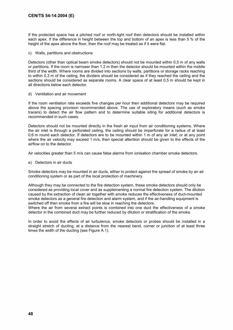
CEN/TS 54-14:2004 (E)
48
If the protected space has a pitched roof or north-light roof then detectors should be installed within each apex. If the difference in height between the top and bottom of an apex is less than 5 % of the height of the apex above the floor, then the roof may be treated as if it were flat.
c) Walls, partitions and obstructions
Detectors (other than optical beam smoke detectors) should not be mounted within 0,5 m of any walls or partitions. If the room is narrower than 1.2 m then the detector should be mounted within the middle third of the width. Where rooms are divided into sections by walls, partitions or storage racks reaching to within 0,3 m of the ceiling, the dividers should be considered as if they reached the ceiling and the sections should be considered as separate rooms. A clear space of at least 0,5 m should be kept in all directions below each detector.
d) Ventilation and air movement
If the room ventilation rate exceeds five changes per hour then additional detectors may be required above the spacing provision recommended above. The use of exploratory means (such as smoke tracers) to detect the air flow pattern and to determine suitable siting for additional detectors is recommended in such cases.
Detectors should not be mounted directly in the fresh air input from air conditioning systems. Where the air inlet is through a perforated ceiling, the ceiling should be imperforate for a radius of at least 0,6 m round each detector. If detectors are to be mounted within 1 m of any air inlet, or at any point where the air velocity may exceed 1 m/s, then special attention should be given to the effects of the airflow on to the detector.
Air velocities greater than 5 m/s can cause false alarms from ionisation chamber smoke detectors.
e) Detectors in air ducts
Smoke detectors may be mounted in air ducts, either to protect against the spread of smoke by an air conditioning system or as part of the local protection of machinery. Although they may be connected to the fire detection system, these smoke detectors should only be considered as providing local cover and as supplementing a normal fire detection system. The dilution caused by the extraction of clean air together with smoke reduces the effectiveness of duct-mounted smoke detectors as a general fire detection and alarm system, and if the air-handling equipment is switched off then smoke from a fire will be slow in reaching the detectors. Where the air from several extract points is combined into one duct the effectiveness of a smoke detector in the combined duct may be further reduced by dilution or stratification of the smoke.
In order to avoid the effects of air turbulence, smoke detectors or probes should be installed in a straight stretch of ducting, at a distance from the nearest bend, corner or junction of at least three times the width of the ducting (see Figure A.1).
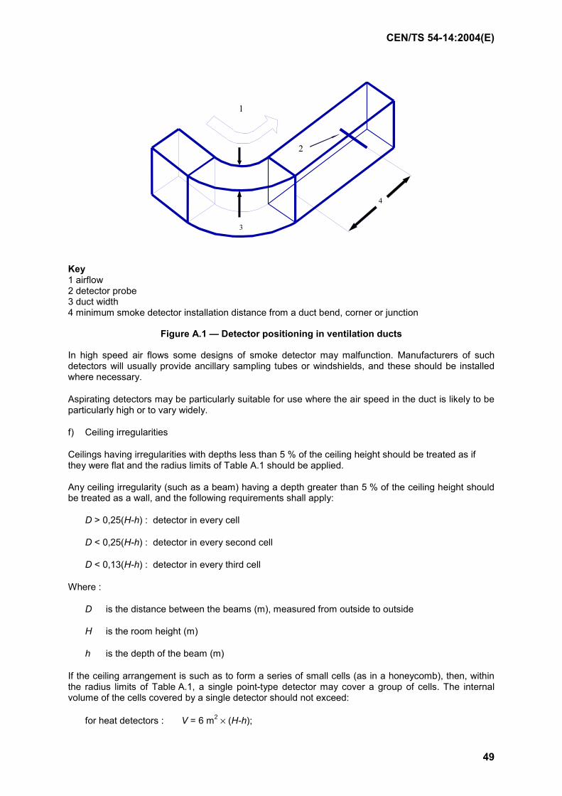
CEN/TS 54-14:2004(E)
49
4
2
3
1
Key 1 airflow 2 detector probe 3 duct width 4 minimum smoke detector installation distance from a duct bend, corner or junction
Figure A.1 — Detector positioning in ventilation ducts
In high speed air flows some designs of smoke detector may malfunction. Manufacturers of such detectors will usually provide ancillary sampling tubes or windshields, and these should be installed where necessary.
Aspirating detectors may be particularly suitable for use where the air speed in the duct is likely to be particularly high or to vary widely.
f) Ceiling irregularities
Ceilings having irregularities with depths less than 5 % of the ceiling height should be treated as if they were flat and the radius limits of Table A.1 should be applied. Any ceiling irregularity (such as a beam) having a depth greater than 5 % of the ceiling height should be treated as a wall, and the following requirements shall apply:
D > 0,25(H-h) : detector in every cell
D < 0,25(H-h) : detector in every second cell
D < 0,13(H-h) : detector in every third cell
Where :
D is the distance between the beams (m), measured from outside to outside
H is the room height (m)
h is the depth of the beam (m)
If the ceiling arrangement is such as to form a series of small cells (as in a honeycomb), then, within the radius limits of Table A.1, a single point-type detector may cover a group of cells. The internal volume of the cells covered by a single detector should not exceed:
for heat detectors : V = 6 m2 × (H-h);
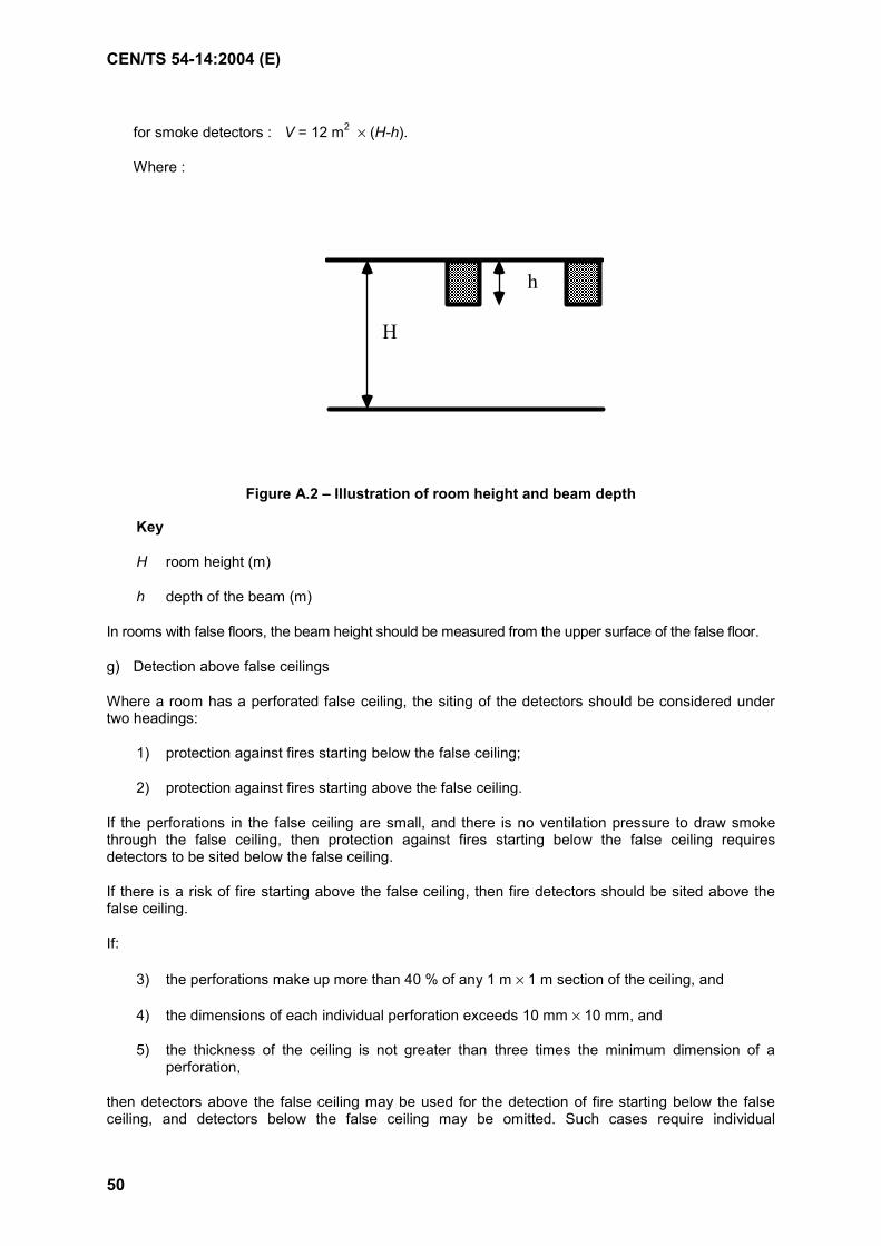
CEN/TS 54-14:2004 (E)
50
for smoke detectors : V = 12 m2 × (H-h).
Where :
Figure A.2 – Illustration of room height and beam depth
Key
H room height (m)
h depth of the beam (m)
In rooms with false floors, the beam height should be measured from the upper surface of the false floor.
g) Detection above false ceilings
Where a room has a perforated false ceiling, the siting of the detectors should be considered under two headings:
1) protection against fires starting below the false ceiling;
2) protection against fires starting above the false ceiling.
If the perforations in the false ceiling are small, and there is no ventilation pressure to draw smoke through the false ceiling, then protection against fires starting below the false ceiling requires detectors to be sited below the false ceiling.
If there is a risk of fire starting above the false ceiling, then fire detectors should be sited above the false ceiling.
If:
3) the perforations make up more than 40 % of any 1 m × 1 m section of the ceiling, and
4) the dimensions of each individual perforation exceeds 10 mm × 10 mm, and
5) the thickness of the ceiling is not greater than three times the minimum dimension of a perforation,
then detectors above the false ceiling may be used for the detection of fire starting below the false ceiling, and detectors below the false ceiling may be omitted. Such cases require individual
H
h

CEN/TS 54-14:2004(E)
51
consideration based on the type, number and area of the perforations, the type and quantity of combustible, and the degree of ventilation which might draw smoke through the false ceiling.
h) Detection below false floors
Where rooms have false floors, detectors should be mounted below the floors as if the under-floor void was another room, unless:
1) the false floor is perforated as specified in A.6.3.1.8 a) to c), or
2) the false floor is of material having a reaction to fire rating of class A11, A21 or B1 (see EN 13501-1) and there is no fire load beneath it.
i) Detectors not under ceilings
In the absence of a ceiling or stratification layer, the fire products will be confined to the rising plume above the fire. If heat or smoke detectors are used to detect fire products in the rising plume (such as where optical beam detectors are used at low levels in atria, or where detectors are used without ceilings) then the limits of operating height should be as given in Table A.1, and the effective operating radius (for either heat or smoke detectors) should be taken as 12,5 % of the height of the detector above the highest likely seat of fire. A.6.4.2 Heat and smoke detectors
Each protected room or enclosed space should contain at least one detector.
A.6.4.3 Flame detectors
No further recommendations.
A.6.4.4 Manual call points
Manual call points should be so located that no person in the premises need travel more than 30 m to reach a manual call point. In premises where the expected users may be handicapped in movement the travel distance should be reduced.
It may be necessary to install manual call points in relatively close proximity to particular fire hazards. Particular attention should be taken, that these manual call points can still be operated when required.
In general, manual call points should be fixed at a height of between 1,2 m and 1,6 m above the floor.
A.6.4.5 Identification
If detector labels are used to provide the necessary cross-relation between detectors and control and indicating equipment, then identification numbers or letters should be attached to or adjacent detectors and manual call points duplicating the indications given at the control and indicating equipment. This identification should be visible from the floor, without requiring the use of ladders or similar equipment. If the detectors are hidden (e.g. above false ceilings or under floors) then duplicate identifications should be provided which are visible from the floor.
A.6.5 Alarm systems and devices
A.6.5.1 General
No further recommendations.
CEN/TS 54-14:2004 (E)
52
A.6.5.2 Sound signals
a) Sound levels
The fire alarm sound should have a minimum level of either 65 dB(A), or 5 dB(A) above any other noise likely to persist for a period longer than 30 s, whichever is the greater. If the alarm is intended to arouse sleeping persons then the minimum sound level at the bedhead should be 75 dB(A).
These minimum levels should be reached at any point at which the alarm sound is required to be heard.
The sound level should not exceed 120 dB(A) at any point where people are likely to be.
If required, sound levels should be measured using an instrument complying with IEC 651, type 2, with slow response and 'A' weighting.
b) Sound frequency
The fire alarm sound should be in a frequency range easily audible to the usual occupants of the building. In general, sounds having a significant part of their energy in the range from 500 Hz to 2000 Hz will be audible to most people.
c) Alarm devices
The number and type of fire alarm devices used should be sufficient to produce the sound level recommended in A.6.4.1.1.
A minimum of two sounders should be provided in the building even if the recommended sound level could be achieved with a single sounder.
At least one sounder should be provided in each fire compartment.
It is unlikely that sound levels in a room will be satisfactory if it is separated from the nearest sounder by more than one door. A larger number of quieter sounders rather than a few very loud sounders may be preferable in order to prevent excessive sound levels in some areas.
d) Sound continuity
The sound of the fire alarm should be continuous. In special circumstances intermittent sounders or a variation in frequency and amplitude, as in a warbling note, can also be used, if the users of the premise are trained in this fire response strategy and a misinterpretation by visitors is excluded.
e) Voice alarm systems
Where the transmitted alarm is a voice message the following should be ensured:
1) that a suitable alarm (either recorded or synthesized) is provided which can be automatically transmitted in response to a fire signal, either immediately or after an agreed delay; this transmission should not depend on the presence of an operator;
2) that all voice messages are clear, short, unambiguous and, as far as practicable, pre-planned;
3) that the level of sound in the building satisfies A.6.4.1.1, except that the level should be at least 10 dB(A) above other sounds likely to persist for 30 s or more;
4) that the received sound is understandable;

CEN/TS 54-14:2004(E)
53
5) that other signals, e.g. meal-break, start and stop work, cannot be confused with the fire alarm signals and that fire alarm signals have the highest priority;
6) that the time interval between successive messages does not exceed 30 s, and that 'fill-in' signals similar to those of conventional sounders are used wherever periods of silence might otherwise exceed 10 s;
7) that during fire alarm conditions all audio input sources are automatically disconnected except for the fire microphone(s) (see (h)) and the speech modules (or equivalent message generators) which give the warning;
8) that if the fire routine requires messages to be given by a person, one or more microphones should be designated as fire microphones. These should be retained in circuit so that announcements and instructions (relating only to the emergency) can be given; Access to the fire microphones should be limited to authorised persons.
f) Use of the fire alarm sound for other purposes
In general fire alarm sounds should be used for other purposes only if the response required is identical to that which would be required in a fire, i.e. immediate evacuation of the area in which the alarm is sounding by the use of any route designated as a fire exit. If any other response is required then the fire alarm sounds should not be used unless accompanied by other information.
A.6.6 Control and indication
A.6.6.1 Location of control and indicating equipment
Where control and indicating equipment is remote from the fire brigade entrance, there may be requirements for signs showing the location of the control and indicating equipment. These requirements should be considered in the consultations of 5.2.
A.6.6.2 Repeat indications
No further recommendations.
A.6.6.3 Repeat controls
No further recommendations.
A.6.6.4 Alarm location aids
A clear and properly orientated zone map (which may be a mimic diagram) or a set of zone cards should be provided near to the control equipment. Additional zone maps or zone cards may be necessary at other locations to meet the requirements of fire brigades, etc, as defined in the consultations of 5.2.
A.6.7 Power supplies
A.6.7.1 Power supply equipment
No further recommendations.
A.6.7.2 Main power source
No further recommendations.
CEN/TS 54-14:2004 (E)
54
A.6.7.3 Standby supply
To allow for possible failures of equipment or of the incoming main supply, the standby supply should be capable of maintaining the system in operation for at least 72 h, after which sufficient capacity should remain to provide the alarm load for at least 30 min.
Where there will be immediate notification of failure, either by local or remote supervision of the system, and a repair contract is in force giving a maximum repair period of less than 24 h, then the minimum standby capacity may be reduced from 72 h to 30 h. The period may be further reduced to 4 h if spares, repair personnel and a standby generator are available on-site at all times.
The standby durations given above are considered sufficient for most normal applications. There will be some applications in which greater durations are required. Where increases are to be made the requirements should be considered in the consultations of 5.2.
NOTE 1 Allowance should be made for reduction in battery capacity due to ageing. In general the use of an initial capacity 25 % higher than the calculated capacity has been found to be satisfactory.
NOTE 2 Battery capacities are usually specified in terms of the current which can be delivered in a 20 hr discharge period. Under higher discharge rates (such as may be found in the alarm condition) the battery capacity may be significantly below its nominal value. Advice should be obtained from the battery manufacturer.
A.6.8 Signals to a fire alarm receiving station
No further recommendations.
A.6.9 Other equipment or systems
No further recommendations.
A.6.10 Cables and interconnections
A.6.10.1 Cable types
No further recommendations.
A.6.10.2 Protection against fire
a) General
Cables which may need to function for more than 1 minute after detection of a fire should either be able to withstand the effects of fire and firefighting for at least 30 min or be given suitable protection able to withstand the effects for that period. Such cables may include:
1) interconnections between a control and indicating equipment and any separate power supply equipment; including cables between alarm devices and their power supply;
2) interconnections between separated parts of a control and indicating equipment;
3) interconnections between a main control and indicating equipment and any repeat indicator panel;
4) interconnections between a main control and indicating equipment and any repeat control panel;
5) any cable which may be required to operate after a delay for investigation of the fire.
CEN/TS 54-14:2004(E)
55
b) Special Requirements for cables joining control equipment to other devices (detectors, manual call points, alarm devices etc.)
1) Spur lines
These should either:
i) be run through an area which is covered by fire detection devices in such a way that the occurrence of fire will lead to an alarm condition at the CIE; or
ii) be able to withstand the effects of fire and firefighting for at least 30 min or be given suitable protection able to withstand the effects for that period.
2) Loops
A large fire in a single unprotected compartment is likely to cause multiple faults to the cable of any unprotected circuit in that compartment. Where faults resulting from such a fire may:
i) adversely affect functions (other than detection) in more than one zone; and
ii) these functions are essential to the fire routine for a period as specified in the documentation of 5.6,
then the circuit’s cables within that compartment should be given sufficient protection to enable them to withstand the effects of fire and firefighting for the specified period or for 30 min, whichever is the greater
A.7 Installation
A.7.1 General
No further recommendations
A.7.2 Siting and accommodation of equipment
No further recommendations.
A.7.3 Cable installation
A.7.3.1 General
No further recommendations.
A.7.3.2 Cable ducts, channels and trunking
No further recommendations.
A.7.3.3 Cable routing
The cables which interconnect the components of a fire alarm system themselves form an important part of the system, and it is essential that they suffer no interference. Such interference could come from two main sources:
a) Mishandling, disconnection or other manual interference with the cable, often while cables of other systems are being worked on;
CEN/TS 54-14:2004 (E)
56
b) Electrical interference, often due to the proximity of other cables carrying strong transient power or signals.
To reduce such interference fire alarm cables should be segregated from cables of other systems. Segregation can be achieved by one or more of the following:
c) installation in conduit, ducting, trunking or channels reserved for fire alarm cables :
1) separation from other cables by a mechanically strong, rigid and continuous partition of material meeting the requirements of classes A1, A2 or B of EN 13501-1;
2) mounting at an adequate distance (usually at least 0,3 m) from cables of other systems;
3) the use of electrically shielded cables.
Fire alarm cables should be either :
d) suitably marked or labelled at intervals not exceeding 2 m to indicate their function and the need for segregation; or
e) coloured throughout the length of the cable sheath or outer covering by a distinctive colour (e.g. red); or
f) enclosed in ducting, trunking or a channel reserved for fire alarm circuits and marked to indicate this reservation.
Where fire alarm cables are mounted in reserved ducting, trunking or channels, the cables should be completely enclosed when the covers of the ducting, trunking or channelling are in place, and all covers should be securely fixed.
Where multicore cable, flexible cable or flexible cord are used for interconnections in fire alarm circuits, none of the cores should be used for circuits other than those of fire alarms.
Cables carrying power in excess of extra-low voltage should be separated from other fire alarm cables. In particular, the mains supply cable should not be brought in through the same cable entry as cables carrying extra-low voltage power or signals.
Segregation of the fire alarm power supply cables need not be applied on the supply side of the isolating protective device (see 6.8.2).
A.8 Commissioning and verification
No further recommendations
A.9 Third party approval
No further recommendations.
A.10 Use of the system
No further recommendations.
CEN/TS 54-14:2004(E)
57
A.11 Maintenance
A.11.1 General
No further recommendations.
A.11.2 Inspection and servicing
A.11.2.1 Maintenance routine
The following maintenance routine should be adopted.
a) Daily attention
The user and/or owner should ensure that on every working day a check is made:
1) that either the panel indicates quiescent condition, or that any variations from quiescent conditions are recorded in the log book and where appropriate reported to the servicing organisation;
2) that any alarm recorded since the previous working day has received appropriate attention;
3) that, where appropriate, the system has been properly restored after any disablement, testing or silencing.
Any defect observed should be recorded in the log book and corrective action should be taken as soon as possible.
b) Monthly attention
At least once a month the user and/or owner should ensure that:
1) any standby generator required to meet the recommendations of 6.8.3 is started, and that its fuel levels are checked and, where necessary, replenished :
i) that the reserves of paper, ink or ribbon on any printer are adequate;
ii) that the indicator test facility (as required under 12.11 of EN 54-2:1997) is operated and any defective indicator is noted.
Any defect observed should be recorded in the log book and corrective action should be taken as soon as possible.
c) Quarterly attention
At least once every 3 months the user and/or owner should ensure that a competent person:
1) checks all entries in the log book and takes any action necessary to bring the system into correct operation;
2) operates at least one detector or manual call point in each zone, to test whether the control and indicating equipment receives and displays the correct signal, sound the alarm and operates any other warning or ancillary devices;
NOTE A procedure should be adopted that ensures that deleterious functions such as the release of extinguishant are not carried out.
CEN/TS 54-14:2004 (E)
58
3) checks the fault monitoring functions of the control and indicating equipment;
4) checks the ability of the control and indicating equipment to operate any door holding or door release function;
5) where permissible, operates any link to the fire brigade or remote manned centre;
6) carries out all further checks and tests specified by the installer, supplier or manufacturer;
7) enquires whether there have been any structural or occupancy changes which might have affected the requirements for the siting of manual call points, detectors and sounders, and if so carries out the visual inspection of A.11.2.1d) 5).
Any defect observed should be recorded in the log book and corrective action should be taken as soon as possible.
d) Yearly attention
At least once every year the user and/or owner should ensure that a competent person:
1) carries out the inspection and test routines recommended daily, monthly and quarterly;
2) checks each detector for correct operation in accordance with the manufacturer's recommendations;
NOTE 1 Although each detector should be checked annually, it is permissible for 25 % of the detectors to be tested at each of the 3-monthly inspections.
3) checks the ability of the control and indicating equipment to operate any ancillary function;
NOTE 2 A procedure should be adopted that ensures that deleterious functions such as the release of extinguishant are not carried out.
4) makes a visual inspection to confirm that all cable fittings and equipment are secure, undamaged and adequately protected;
5) makes a visual inspection to check whether structural or occupancy changes have affected the requirements for the siting of manual call points, detectors and sounders. The visual inspection should also confirm that a clear space of at least 0.5 m is preserved in all directions below every detector and that all manual call points remain unobstructed and conspicuous;
6) examines and tests all batteries.
Any defect observed should be recorded in the logbook and corrective action should be taken as soon as possible.
A.11.3 Special servicing
No further recommendations.
A.11.4 Repair and modification
No further recommendations.
CEN/TS 54-14:2004(E)
59
A.11.5 Spares
No further recommendations.
A.11.6 Documentation
On completion of the quarterly and yearly inspections the body responsible for the testing should provide the responsible person with signed confirmation that testing recommended by A.11.2.1c) and A.11.2.1d) has been completed and that any identified deficiencies of the system have been notified to the responsible person.
A.12 Modification or extension of an installed system
No further recommendations.
A.13 Operation of other fire protection systems
No further recommendations
A.14 Application in special risks
No further recommendations.
A.15 Integrated systems
No further recommendations.
A.16 Hierarchical systems
No further recommendations.
CEN/TS 54-14:2004 (E)
60
Annex B (informative)
False alarms
B.1 Prevention of false alarms
It is essential that the utmost care should be taken by system designers, installers and users to reduce the incidence of false alarms.
False alarms may be the result of poor equipment, poor system design, poor installation, poor usage or poor maintenance. They may also result from adverse environmental conditions not taken into account in the system design.
Common causes of false alarms include the following (not necessarily given in order of importance):
a) work being carried out in a protected area without knowledge of, or in neglect of, the necessary precautions;
b) ambient conditions such as heat, smoke or flame from cooking or work processes, fumes from engine exhausts, or high air velocities;
c) mechanical and electrical faults, often resulting from the effects of vibration, impact or corrosion;
d) servicing or testing work carried out without prior notification to the fire brigade or central alarm station;
e) electrical transients (such as from lightning or switch-on surges) or radio interference (such as from cellular phones);
f) inadequate servicing;
g) the build-up of dust or dirt within a detector, or the entry of insects;
h) change of use or changes within the building;
i) accidental or malicious operation of manual call points or detectors.
B.2 Smoke detectors
False alarms signalled by smoke detectors may be caused by smoke and other fumes, dusts (including slow accumulations of dust and disturbed aerial dusts), fibres, steam or condensation; all these may be due to normal processes or activities or to unusual extremes of the environment. Insect infestation may be a significant problem, particularly in the late summer period.
Optical beam smoke detectors will often give false alarms if the beam is accidentally partially obstructed; apart from those obstructions due to human activities, obstructions due to perching by birds or by bats has been reported. Some types of beam detectors may give false alarms when subjected to bright sunlight or intense light sources such as photographic flash.
CEN/TS 54-14:2004(E)
61
Ionization chamber smoke detectors are highly sensitive to smokes made up of very small particles, including diesel exhausts and fumes from self-cleaning ovens. Some types are sensitive to high air speeds and may give false alarms if mounted in windy situations. Because of the very low currents used in the ionization chambers, high humidity may cause problems, particularly if the detectors have previously been contaminated by materials which can absorb water.
B.3 Heat detectors
False alarms may be caused by abnormal increases in temperature due to space heating equipment, industrial processes or sunshine. They may be prevented by installing detectors with appropriate higher temperature settings, or, in the case of direct sunlight, by introducing an appropriate shade.
False alarms from rate-of-rise heat detectors may also be caused by a rapid temperature increase to normal room conditions following exposure to low temperatures. Such a sequence may occur, for instance, in a loading bay with large doors to the outside; while the doors are open the detector may be exposed to winter conditions, followed by rapid heating when the doors are closed. If such conditions are likely, then detectors without a rate-of-rise response should be used.
B.4 Flame detectors
Ultraviolet flame detectors sense the ultraviolet radiation emitted by flames. They are liable to respond to sources such as lightning, ionizing radiation, ultraviolet lamps and quartz-halogen lamps unless the detection system can discriminate between various sources, but they do not respond to sunlight. (The component of solar ultraviolet to which detectors would respond is filtered out by the high-altitude ozone layer of the earth's atmosphere.) Known sources of ultraviolet light should be screened from the detector, taking care that the screen does not also obscure likely sites for fire. Ordinary window glass will screen ultraviolet radiation.
Most infra-red flame detectors operate by detecting the flickering component of the infra-red radiation from a fire. This type of detector should be insensitive to steady infra-red sources such as very hot objects or sunlight, but may be operated if this steady light becomes modulated by, for example, moving tree branches or the blades of a fan. Infra-red flame detectors may be made solar blind.
B.5 Multi-phenomena systems
Systems are now becoming available in which more than one operating principle is used to detect fire, with the objective of obtaining a better differentiation between fire and non-fire conditions. Such systems may have more than one sensor in a single detector housing, or may combine the readings from several different detectors. Typical combinations may include smoke and heat sensors, ionisation chamber and optical scattering sensors, or infrared and ultraviolet flame sensors.
The benefits of these systems depend on the algorithm used to make the fire decision. The increased amount of information coming from the combination can significantly reduce the number of false alarms caused by environmental conditions.
B.6 Pre-alarm warnings
In some types of system an early warning can be given of conditions which might (or might not) represent a fire. Such pre-warnings should not initiate a full fire alarm, but may be used to alert personnel to the need for an inspection, thus reducing the number of false alarms and possibly giving earlier fire action.
CEN/TS 54-14:2004 (E)
62
B.7 Activity related systems
Where human or industrial activity during working or wakeful hours could result in false alarms, particularly where the presence and behaviour patterns of people make it unlikely that a fire would go undetected by human agency, it may be useful to consider an activity related system. Various options are available and each should be considered in the light of the fire risk and type of occupancy. No such options, for either new or existing systems, should be implemented until agreement has been reached under the procedures outlined in 5.2.
Instances of where activity related systems might be employed include the following:
a) schools;
b) hotels, boarding houses and other residential premises;
c) factory and commercial premises that are active for only part of the day.
A few examples of activity related systems are listed below :
d) the simplest application could be for a system that switched from manual detection during the working hours to automatic detection in silent hours (i.e. outside working hours).
e) in a system which allows variable detection algorithms, it may be possible to use different algorithms (or change the recognition patterns) during working hours so that the system is less likely to give false operation in response to conditions which may commonly arise during working hours.
f) protection by smoke detectors in silent hours could be changed to heat detectors during working hours.
g) as a last resort, a system of pre-transmission confirmation (see B.8) may be used during working hours.
Any condition likely to result in an increased size of fire at detection should be used only when trained staff are present on the premises and a risk assessment has been carried out.
Switching to the silent hours condition should not rely on human action or discretion; it should be an entirely automatic procedure at a predetermined time. The risk of false alarms should be subordinate to the need to guarantee the required level of protection during silent hours. No automatic switching devices should be readily accessible to the system user, except that in places like a hotel bar it is permissible to delay the change to the more sensitive state by a manual switch operation at access level 2. Repeated switch operations may be used to extend the delay, but the delay should not extend more than 45 min after the last operation of the switch. In commercial premises it may sometimes be acceptable for the automatic changeover to occur when the main access door is closed and locked for the night.
Weekends should be pre-programmed into the system time switch. The procedures for dealing with public and works holidays and with time changes to and from Summer Time should be clearly understood by the user, so that the correct degree of cover is available at all times. A manual override switch, on or adjacent to the control equipment, should be available to allow full cover to be provided during periods when the building is unexpectedly unoccupied. The override switch should not be capable of switching the full cover to the restricted cover, and the system design should not permit the action of this switch to be temporarily or permanently cancelled by any automatic function.
An indicator light on, or adjacent to, the control and indicating equipment should show whether the system is switched to the working or silent hours state.

CEN/TS 54-14:2004(E)
63
B.8 Pre-transmission confirmation
In some (but not all) circumstances where there is a high incidence of false alarms which cannot be reduced by other measures, it may be desirable to delay the automatic transmission of an alarm to the fire brigade for a sufficient time to allow the alarm to be investigated. For this purpose the inclusion in the control and indicating equipment of an output delay (allowed as an option under EN 54-2) or the provision of a separate alarm transmission delay unit may be considered.
An alarm transmission delay unit should not be incorporated into a fire alarm system unless the responsible person is satisfied that all other reasonable measures have been taken to prevent false alarms of fire, that the unit would not prejudice the level of fire precautions within the protected premises, that the delay will only be used when staff are available to investigate the cause of the alarm, and that both the proposed unit and the arrangements for its use are acceptable to the fire insurer and the fire brigade. In many applications rapid attendance by the fire brigade is essential, and in such cases the use of transmission delay units will not be acceptable. Even where rapid attendance by the fire brigade is not essential, the total possible delay should be related to the expected attendance time.
If an alarm transmission delay unit is used then the normal sequence of events in the event of an alarm should be as follows:
a) if the alarm is raised by a manual call point then the normal functions of the system in both sounding the internal alarm and transmitting the alarm to the remote centre should continue without delay (i.e. the alarm transmission delay should not operate);
b) if the alarm is initiated by an automatic detector then the call to the fire brigade or central alarm station may be delayed for a search period not exceeding 10 min. During this period the sounding of the internal alarms will depend on decisions made in defining the fire routine (see 5.5);
c) if during the delay period the alarm is found to be a real fire, then a manual operation at the control panel or the operation of any manual call point should cause an immediate transmission of the alarm;
d) if the alarm can be shown to be false, with no actual fire, then the internal alarms should be silenced, a note made of any indication which might throw light on the origin of the alarm, and the system should be reset. Resetting of the system should inhibit transmission of the alarm unless the system again goes into the alarm state.
The system outlined under a) to d) above has a possibility that (if no one starts a search) a delay of up to 10 min might be experienced with no action being taken, but with the fire able to grow and spread. To reduce the risk of this occurring the search period may start with an acknowledgement period, not exceeding 2 min. During this period the existence of an alarm should be acknowledged by a manual action at the control panel. If no acknowledgement action is made, then at the end of the acknowledgement period all delayed outputs should be activated.
An alarm transmission delay should not delay or otherwise affect the operation of audible or visual alarms or any other part of the fire alarm system. The period of delay should only be alterable by properly authorised and trained persons. A simple, accessible alarm transmission switch should also be provided so that a call to the fire brigade can be made without delay if necessary. Satisfactory arrangements (such as a time switch) should be made to disconnect the device during periods when the internal investigation of alarms cannot be undertaken immediately.
If investigations show that the transmission system may have significant delays between the sending of the alarm from the protected premises and its reception by the fire brigade, then these delays should be taken into account in assessing the desirability of an alarm transmission delay unit.

CEN/TS 54-14:2004 (E)
64
B.9 Investigation of false alarms
Installed systems which are the subject of a series of false alarms should be referred to an organisation having specialist knowledge, such as the system designer, installer, maintainer or inspection organisation.
CEN/TS 54-14:2004(E)
65
Annex C (informative)
Model documents
This Annex gives models for :
a) certificate of design;
b) certificate of installation;
c) certificate of commissioning and verification;
d) certificate of acceptance;
e) system logbook.
Although the various certificates are here shown separately, it is permissible (and may be desirable) for them to be combined into one document, or to be bound into the system logbook.

CEN/TS 54-14:2004 (E)
66
CERTIFICATE OF DESIGN
Protected area........................................................................................…………....................................
Address of premises ........................................................................................…………..........................
................................................................................…..............................Tel No.............………..............
Designer’s name........................................................................................…...........................................
Designer’s address ...................................................................................…............................................
........................................................................................................…......Tel No.....………......................
As recommended in Clause 6.13 of CEN/TS 54-14, the design work carried out and covered by this certificate is shown on drawings numbers
..........................................................................................................................…………..........................
I/We hereby certify that the fire detection and alarm system at the above premises has been designed by me/us, and that the system as designed conforms to the appropriate recommendations given in CEN/TS 54-14, (including the requirements covered in the documentation prepared under 5.6) except for such variations as have been agreed in compliance with Clause 4.3 of CEN/TS 54-14 and are listed below.
Type of system (where appropriate).
Signature of person responsible for design of the system...................…………..............................…….
Status ........................................................................………......... Date..............................................
For and on behalf of .................................................………….................................................................
_ _ _ _ _ _ _ _ _ _ _ _ _ _ _ _ _ _ _ _ _ _ _ _ _ _ _ _ _ _ _ _ _ _ _ _ _ _ _ _ _ _ _ _ _ _ _ _ _ _ _ _ _ _
Details of variations from the recommendations of CEN/TS 54-14 (or the numbers of documents in which the details are given).
Additional information:
Figure C.1 — Model certificate of design
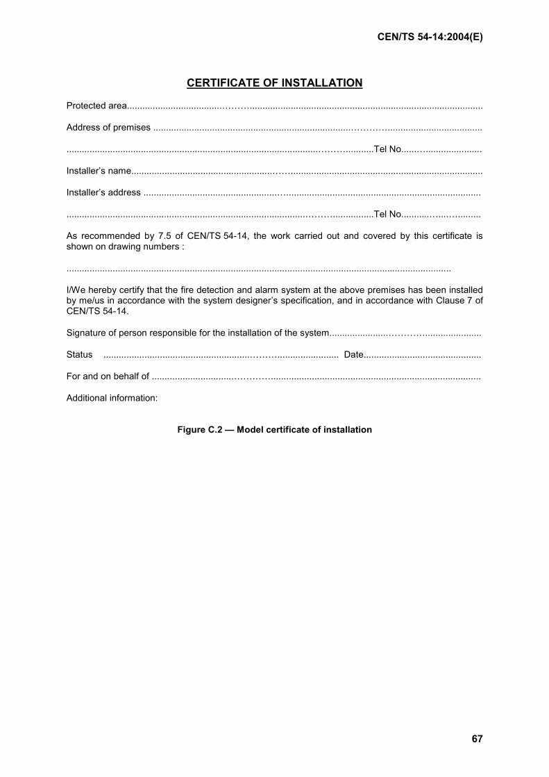
CEN/TS 54-14:2004(E)
67
CERTIFICATE OF INSTALLATION
Protected area.....................................………...........................................................................................
Address of premises .............................................................................………….....................................
..................................................................................................………...........Tel No......…......................
Installer’s name.......................................................……...........................................................................
Installer’s address ....................................................…............................................................................
.............................................................................................………................Tel No...........…....….........
As recommended by 7.5 of CEN/TS 54-14, the work carried out and covered by this certificate is shown on drawing numbers :
......................................................................................................................................................
I/We hereby certify that the fire detection and alarm system at the above premises has been installed by me/us in accordance with the system designer’s specification, and in accordance with Clause 7 of CEN/TS 54-14.
Signature of person responsible for the installation of the system.......................…………......................
Status .........................................................………........................ Date..............................................
For and on behalf of ................................…………..................................................................................
Additional information:
Figure C.2 — Model certificate of installation
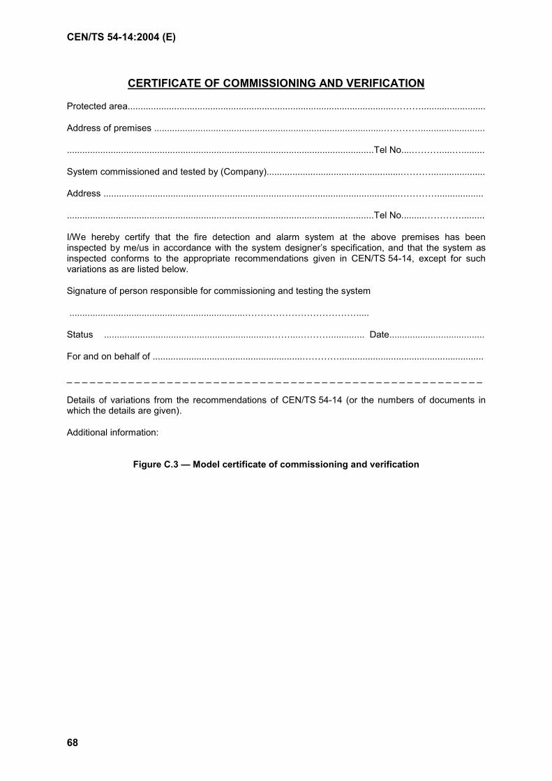
CEN/TS 54-14:2004 (E)
68
CERTIFICATE OF COMMISSIONING AND VERIFICATION
Protected area.......................................................................................................……….........................
Address of premises .........................................................................................………….........................
.......................................................................................................................Tel No....……….....….........
System commissioned and tested by (Company).....................................................……….....................
Address ...................................................................................................................…………..................
.......................................................................................................................Tel No.........………….........
I/We hereby certify that the fire detection and alarm system at the above premises has been inspected by me/us in accordance with the system designer’s specification, and that the system as inspected conforms to the appropriate recommendations given in CEN/TS 54-14, except for such variations as are listed below.
Signature of person responsible for commissioning and testing the system
....................................................................……………………………….....
Status .................................................................……....……….............. Date.....................................
For and on behalf of ..........................................................…………........................................................
_ _ _ _ _ _ _ _ _ _ _ _ _ _ _ _ _ _ _ _ _ _ _ _ _ _ _ _ _ _ _ _ _ _ _ _ _ _ _ _ _ _ _ _ _ _ _ _ _ _ _ _ _ _
Details of variations from the recommendations of CEN/TS 54-14 (or the numbers of documents in which the details are given).
Additional information:
Figure C.3 — Model certificate of commissioning and verification
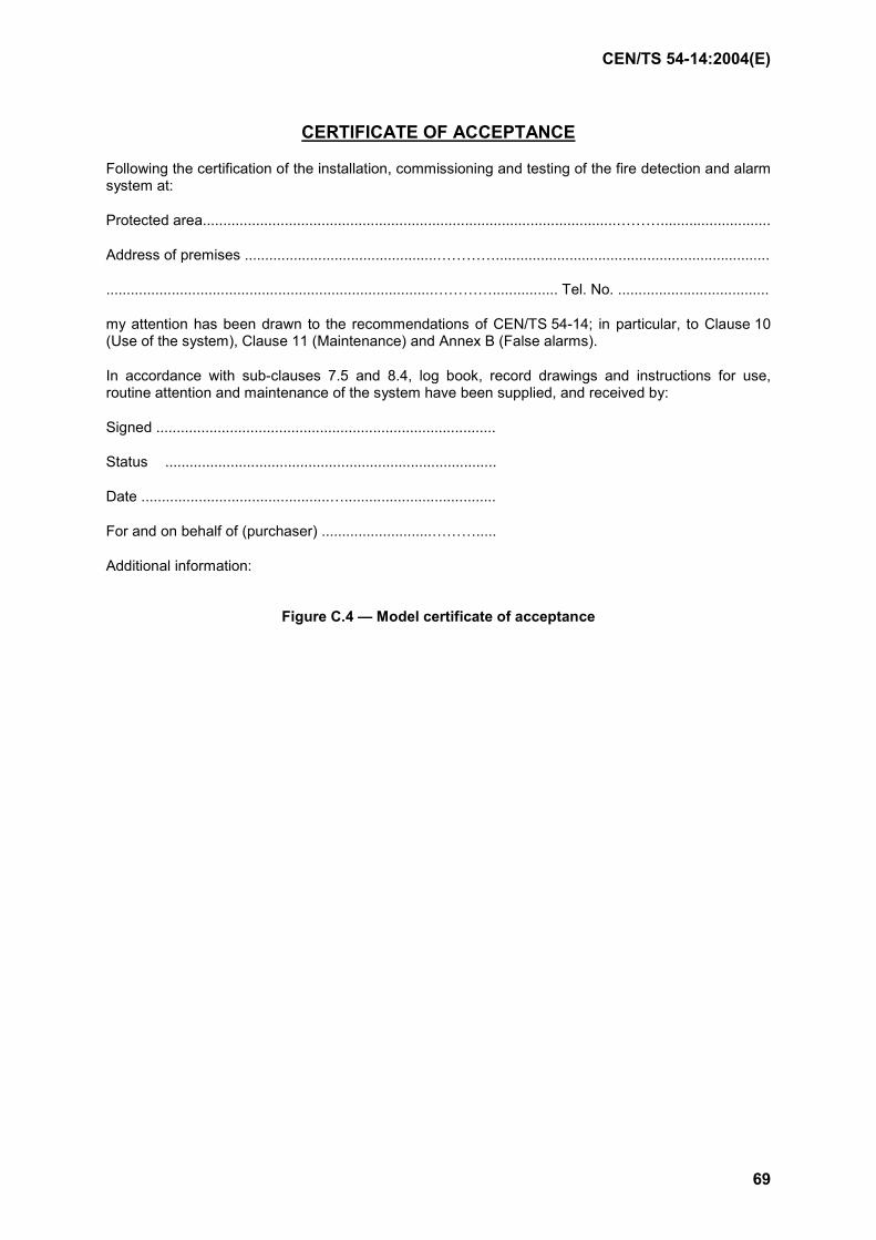
CEN/TS 54-14:2004(E)
69
CERTIFICATE OF ACCEPTANCE
Following the certification of the installation, commissioning and testing of the fire detection and alarm system at:
Protected area.....................................................................................................………...........................
Address of premises ...............................................…………...................................................................
................................................................................…………................ Tel. No. .....................................
my attention has been drawn to the recommendations of CEN/TS 54-14; in particular, to Clause 10 (Use of the system), Clause 11 (Maintenance) and Annex B (False alarms).
In accordance with sub-clauses 7.5 and 8.4, log book, record drawings and instructions for use, routine attention and maintenance of the system have been supplied, and received by:
Signed ...................................................................................
Status .................................................................................
Date ..............................................….....................................
For and on behalf of (purchaser) ...........................……….....
Additional information:
Figure C.4 — Model certificate of acceptance
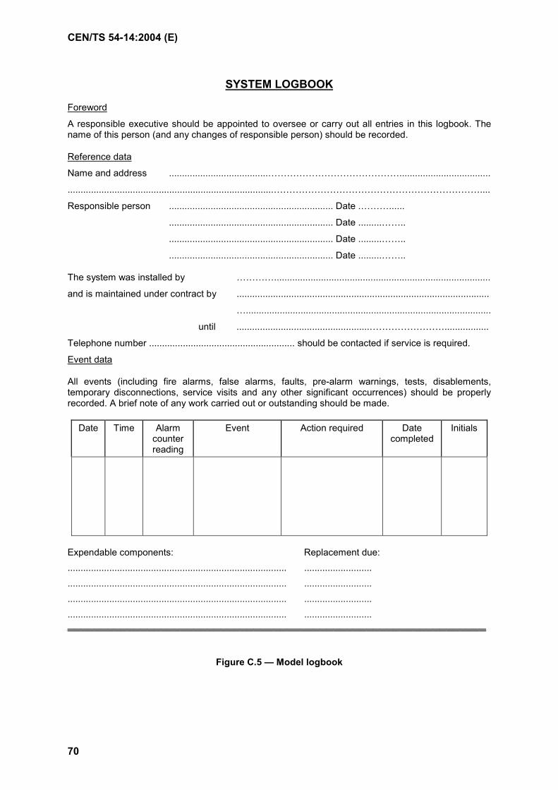
CEN/TS 54-14:2004 (E)
70
SYSTEM LOGBOOK
Foreword
A responsible executive should be appointed to oversee or carry out all entries in this logbook. The name of this person (and any changes of responsible person) should be recorded.
Reference data
Name and address ......................................……………………………………...................................
...............................................................................…………………………………………………………....
Responsible person ............................................................... Date .………......
............................................................... Date .........……..
............................................................... Date .........……..
............................................................... Date .........……..
The system was installed by …………...................................................................................
and is maintained under contract by .................................................................................................
…..............................................................................................
until ...................................................…………………….................
Telephone number ........................................................ should be contacted if service is required.
Event data
All events (including fire alarms, false alarms, faults, pre-alarm warnings, tests, disablements, temporary disconnections, service visits and any other significant occurrences) should be properly recorded. A brief note of any work carried out or outstanding should be made.
Date Time Alarm counter reading
Event Action required Date completed
Initials
Expendable components: Replacement due: .................................................................................... .......................... .................................................................................... .......................... .................................................................................... .......................... .................................................................................... .......................... ═══════════════════════════════════════════════════════════════
Figure C.5 — Model logbook
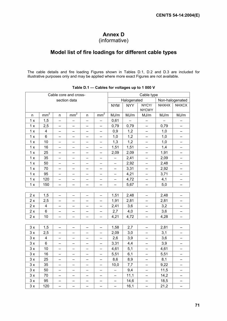
CEN/TS 54-14:2004(E)
71
Annex D (informative)
Model list of fire loadings for different cable types
The cable details and fire loading Figures shown in Tables D.1, D.2 and D.3 are included for illustrative purposes only and may be applied where more exact Figures are not available.
Table D.1 — Cables for voltages up to 1 000 V
Cable core and cross- Cable type section data Halogenated Non-halogenated
NYM NYY NYCY/ NYCWY
NHXHX NHXCX
n mm2 n mm2 n mm2 MJ/m MJ/m MJ/m MJ/m MJ/m 1 x 1,5 – – – – 0,61 – – – – 1 x 2,5 – – – – 0,79 0,79 – 0,79 – 1 x 4 – – – – 0,9 1,2 – 1,0 – 1 x 6 – – – – 1,0 1,2 – 1,0 – 1 x 10 – – – – 1,3 1,2 – 1,0 – 1 x 16 – – – – 1,51 1,51 – 1,4 – 1 x 25 – – – – 2,09 2,09 – 1,91 – 1 x 35 – – – – – 2,41 – 2,09 – 1 x 50 – – – – – 2,92 – 2,48 – 1 x 70 – – – – – 3,31 – 2,92 – 1 x 95 – – – – – 4,21 – 3,71 – 1 x 120 – – – – – 4,72 – 4,1 – 1 x 150 – – – – – 5,67 – 5,0 –
2 x 1,5 – – – – 1,51 2,48 – 2,48 – 2 x 2,5 – – – – 1,91 2,81 – 2,81 – 2 x 4 – – – – 2,41 3,6 – 3,2 – 2 x 6 – – – – 2,7 4,0 – 3,6 – 2 x 10 – – – – 4,21 4,72 – 4,28 –
3 x 1,5 – – – – 1,58 2,7 – 2,81 – 3 x 2,5 – – – – 2,09 3,0 – 3,1 – 3 x 4 – – – – 2,6 3,9 – 3,6 – 3 x 6 – – – – 3,31 4,4 – 3,9 – 3 x 10 – – – – 4,61 5,1 – 4,61 – 3 x 16 – – – – 5,51 6,1 – 5,51 – 3 x 25 – – – – 8,6 8,9 – 8,1 – 3 x 35 – – – – 10,0 7,7 – 9,22 – 3 x 50 – – – – – 9,4 – 11,5 – 3 x 70 – – – – – 11,1 – 14,2 – 3 x 95 – – – – – 14,6 – 18,5 – 3 x 120 – – – – – 16,1 – 21,2 –
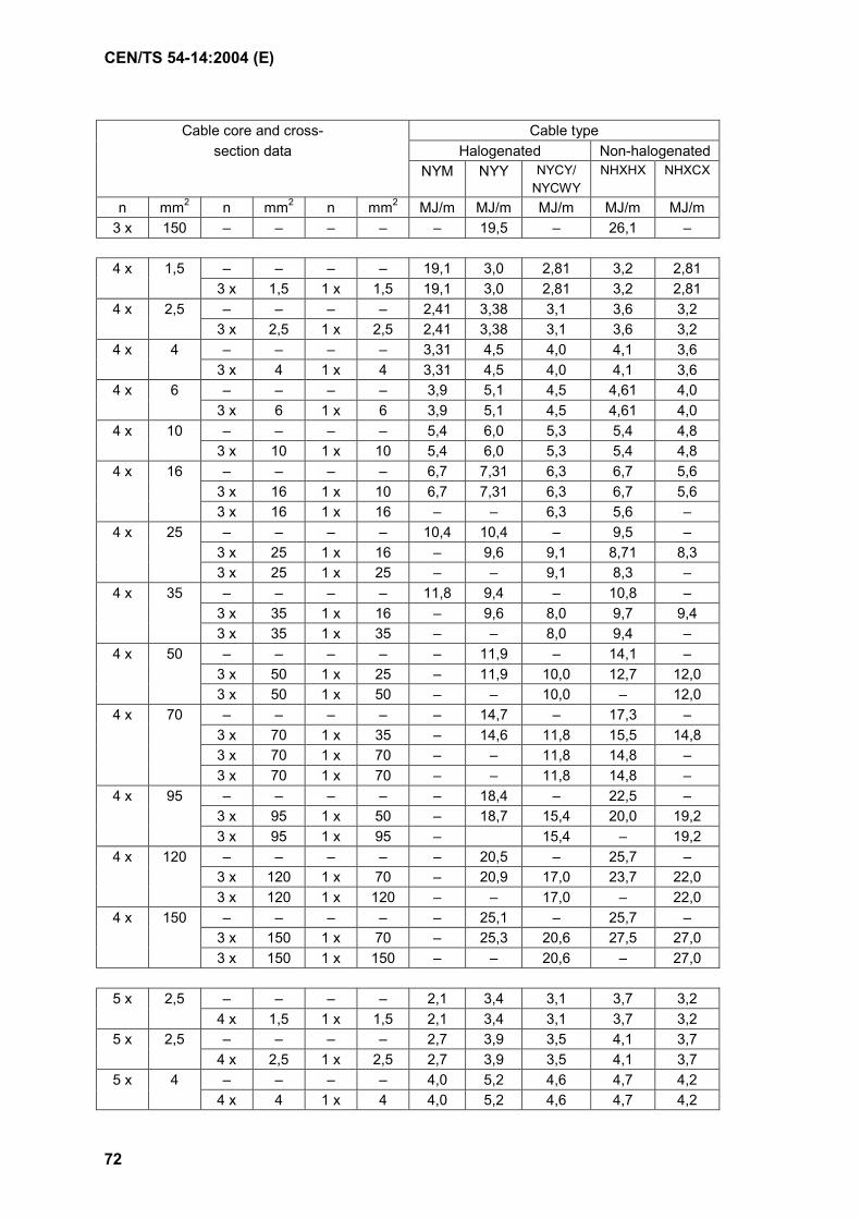
CEN/TS 54-14:2004 (E)
72
Cable core and cross- Cable type section data Halogenated Non-halogenated
NYM NYY NYCY/ NYCWY
NHXHX NHXCX
n mm2 n mm2 n mm2 MJ/m MJ/m MJ/m MJ/m MJ/m 3 x 150 – – – – – 19,5 – 26,1 –
4 x 1,5 – – – – 19,1 3,0 2,81 3,2 2,81
3 x 1,5 1 x 1,5 19,1 3,0 2,81 3,2 2,81 4 x 2,5 – – – – 2,41 3,38 3,1 3,6 3,2
3 x 2,5 1 x 2,5 2,41 3,38 3,1 3,6 3,2 4 x 4 – – – – 3,31 4,5 4,0 4,1 3,6
3 x 4 1 x 4 3,31 4,5 4,0 4,1 3,6 4 x 6 – – – – 3,9 5,1 4,5 4,61 4,0
3 x 6 1 x 6 3,9 5,1 4,5 4,61 4,0 4 x 10 – – – – 5,4 6,0 5,3 5,4 4,8
3 x 10 1 x 10 5,4 6,0 5,3 5,4 4,8 4 x 16 – – – – 6,7 7,31 6,3 6,7 5,6
3 x 16 1 x 10 6,7 7,31 6,3 6,7 5,6 3 x 16 1 x 16 – – 6,3 5,6 –
4 x 25 – – – – 10,4 10,4 – 9,5 – 3 x 25 1 x 16 – 9,6 9,1 8,71 8,3 3 x 25 1 x 25 – – 9,1 8,3 –
4 x 35 – – – – 11,8 9,4 – 10,8 – 3 x 35 1 x 16 – 9,6 8,0 9,7 9,4 3 x 35 1 x 35 – – 8,0 9,4 –
4 x 50 – – – – – 11,9 – 14,1 – 3 x 50 1 x 25 – 11,9 10,0 12,7 12,0 3 x 50 1 x 50 – – 10,0 – 12,0
4 x 70 – – – – – 14,7 – 17,3 – 3 x 70 1 x 35 – 14,6 11,8 15,5 14,8 3 x 70 1 x 70 – – 11,8 14,8 – 3 x 70 1 x 70 – – 11,8 14,8 –
4 x 95 – – – – – 18,4 – 22,5 – 3 x 95 1 x 50 – 18,7 15,4 20,0 19,2 3 x 95 1 x 95 – 15,4 – 19,2
4 x 120 – – – – – 20,5 – 25,7 – 3 x 120 1 x 70 – 20,9 17,0 23,7 22,0 3 x 120 1 x 120 – – 17,0 – 22,0
4 x 150 – – – – – 25,1 – 25,7 – 3 x 150 1 x 70 – 25,3 20,6 27,5 27,0 3 x 150 1 x 150 – – 20,6 – 27,0
5 x 2,5 – – – – 2,1 3,4 3,1 3,7 3,2 4 x 1,5 1 x 1,5 2,1 3,4 3,1 3,7 3,2
5 x 2,5 – – – – 2,7 3,9 3,5 4,1 3,7 4 x 2,5 1 x 2,5 2,7 3,9 3,5 4,1 3,7
5 x 4 – – – – 4,0 5,2 4,6 4,7 4,2 4 x 4 1 x 4 4,0 5,2 4,6 4,7 4,2
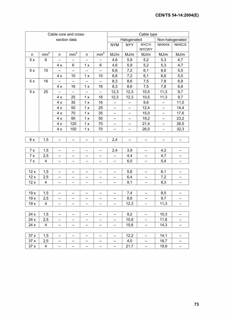
CEN/TS 54-14:2004(E)
73
Cable core and cross- Cable type section data Halogenated Non-halogenated
NYM NYY NYCY/ NYCWY
NHXHX NHXCX
n mm2 n mm2 n mm2 MJ/m MJ/m MJ/m MJ/m MJ/m 5 x 6 – – – – 4,6 5,9 5,2 5,3 4,7
4 x 6 1 x 6 4,6 5,9 5,2 5,3 4,7 5 x 10 – – – – 6,6 7,2 6,1 6,6 5,5
4 x 10 1 x 10 6,6 7,2 6,1 6,6 5,5 5 x 16 – – – – 8,3 8,6 7,5 7,8 6,8
4 x 16 1 x 16 8,3 8,6 7,5 7,8 6,8 5 x 25 – – – – 12,3 12,3 10,5 11,3 9,7
4 x 25 1 x 16 12,3 12,3 10,5 11,3 9,7 4 x 35 1 x 16 – – 9,6 – 11,0 4 x 50 1 x 25 – – 12,4 – 14,4 4 x 70 1 x 35 – – 15,0 – 17,6 4 x 95 1 x 50 – – 19,2 – 23,2 4 x 120 1 x 70 – – 21,4 – 26,5 4 x 150 1 x 70 – – 26,0 – 32,3
6 x 1,5 – – – – 2,4 – – – –
7 x 1,5 – – – – 2,4 3,9 – 4,2 – 7 x 2,5 – – – – – 4,4 – 4,7 – 7 x 4 – – – – – 6,0 – 5,4 –
12 x 1,5 – – – – – 5,6 – 6,1 – 12 x 2,5 – – – – – 6,4 – 7,2 – 12 x 4 – – – – – 9,1 – 8,3 –
19 x 1,5 – – – – – 7,4 – 8,5 – 19 x 2,5 – – – – – 8,8 – 9,7 – 19 x 4 – – – – – 12,3 – 11,3 –
24 x 1,5 – – – – – 9,2 – 10,3 – 24 x 2,5 – – – – – 10,6 – 11,8 – 24 x 4 – – – – – 15,6 – 14,3 –
37 x 1,5 – – – – – 12,2 – 14,1 – 37 x 2,5 – – – – – 4,0 – 16,7 – 37 x 4 – – – – – 21,7 – 19,9 –
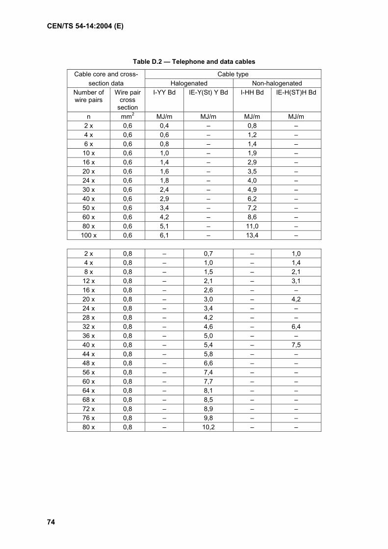
CEN/TS 54-14:2004 (E)
74
Table D.2 — Telephone and data cables
Cable core and cross- Cable type section data Halogenated Non-halogenated
Number of wire pairs
Wire pair cross
section
I-YY Bd IE-Y(St) Y Bd I-HH Bd IE-H(ST)H Bd
n mm2 MJ/m MJ/m MJ/m MJ/m 2 x 0,6 0,4 – 0,8 – 4 x 0,6 0,6 – 1,2 – 6 x 0,6 0,8 – 1,4 – 10 x 0,6 1,0 – 1,9 – 16 x 0,6 1,4 – 2,9 – 20 x 0,6 1,6 – 3,5 – 24 x 0,6 1,8 – 4,0 – 30 x 0,6 2,4 – 4,9 – 40 x 0,6 2,9 – 6,2 – 50 x 0,6 3,4 – 7,2 – 60 x 0,6 4,2 – 8,6 – 80 x 0,6 5,1 – 11,0 – 100 x 0,6 6,1 – 13,4 –
2 x 0,8 – 0,7 – 1,0 4 x 0,8 – 1,0 – 1,4 8 x 0,8 – 1,5 – 2,1 12 x 0,8 – 2,1 – 3,1 16 x 0,8 – 2,6 – – 20 x 0,8 – 3,0 – 4,2 24 x 0,8 – 3,4 – – 28 x 0,8 – 4,2 – – 32 x 0,8 – 4,6 – 6,4 36 x 0,8 – 5,0 – – 40 x 0,8 – 5,4 – 7,5 44 x 0,8 – 5,8 – – 48 x 0,8 – 6,6 – – 56 x 0,8 – 7,4 – – 60 x 0,8 – 7,7 – – 64 x 0,8 – 8,1 – – 68 x 0,8 – 8,5 – – 72 x 0,8 – 8,9 – – 76 x 0,8 – 9,8 – – 80 x 0,8 – 10,2 – –

CEN/TS 54-14:2004(E)
75
Table D.3 — Cables for voltages over 1 000 V
Cable core and cross- Cable type section data Halogenated Non-halogenated
NA2 x SEY NYSEY – – n mm2 n mm2 MJ/m MJ/m – – 3x 35 1 x 16 37,0 38,0 – – 3x 50 1 x 16 42,0 42,0 – – 3x 70 1 x 16 47,0 39,1 – – 3x 95 1 x 16 53,0 53,0 – – 3x 120 1 x 16 60,0 58,0 – –
CEN/TS 54-14:2004 (E)
76
Bibliography
EN 54-2:1997, Fire detection and fire alarm systems – Part 2: Control and indicating equipment
EN 54-3, Fire detection and fire alarm systems – Part 3: Fire alarm devices – Sounders
EN 54-4, Fire detection and fire alarm systems – Part 4: Power supply equipment
EN 54-5, Fire detection and fire alarm systems – Part 5: Heat detectors – Point detectors
EN 54-7, Fire detection and fire alarm systems – Part 7: Smoke detectors – Point detectors using scattered light, transmitted light or ionization
EN 54-10, Fire detection and fire alarm systems – Part 10: Flame detectors – Point detectors
EN 54-11, Fire detection and fire alarm systems – Part 11: Manual call points
EN 54-12, Fire detection and fire alarm systems - Part 12: Smoke detectors — Line detectors using an optical light beam
prEN 54-13, Fire detection and fire alarm systems - Part 13: System requirements
prEN 54-17, Fire detection and fire alarm systems - Part 17: Short circuit isolators
EN 13501-1, Fire classification of construction products and building elements — Part 1: Classification using test data from reaction to fire tests


ICS 13.220.20 Klasifikaciona grupa Z.C7Deskriptori: bezbednost od požara u zgradama, požarni alarmi, projektovanje, održavanje, tehnički prijem Descriptors: fire safety in buildings, fire alarms, design, maintenance, commissioning Ukupno strana 76