Embed Size (px)
Citation preview
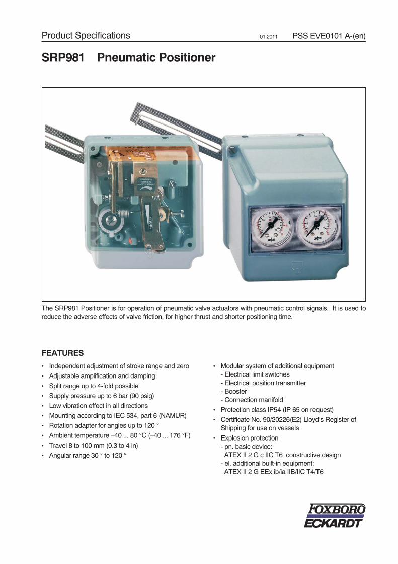
FEATURES
• Independent adjustment of stroke range and zero
• Adjustable amplification and damping
• Split range up to 4-fold possible
• Supply pressure up to 6 bar (90 psig)
• Low vibration effect in all directions
• Mounting according to IEC 534, part 6 (NAMUR)
• Rotation adapter for angles up to 120 °
• Ambient temperature –40 ... 80 °C (–40 ... 176 °F)
• Travel 8 to 100 mm (0.3 to 4 in)
• Angular range 30 ° to 120 °
• Modular system of additional equipment- Electrical limit switches- Electrical position transmitter- Booster- Connection manifold
• Protection class IP54 (IP 65 on request)
• Certificate No. 90/20226(E2) Lloyd’s Register ofShipping for use on vessels
• Explosion protection- pn. basic device:ATEX II 2 G c IIC T6 constructive design
- el. additional built-in equipment:ATEX II 2 G EEx ib/ia IIB/IIC T4/T6
SRP981 Pneumatic Positioner
The SRP981 Positioner is for operation of pneumatic valve actuators with pneumatic control signals. It is used toreduce the adverse effects of valve friction, for higher thrust and shorter positioning time.
Product Specifications 01.2011 PSS EVE0101 A-(en)

2 SRP981 PSS EVE0101 A-(en)
SPEZIAL VERSIONS OF SRP981
SRP981 in Stainless Steel housing
Casing . . . . . . . . . . . . . . . . . Stainless Steel 1.4404 / 316L,1.25 mm thick
Ingress Protection . . . . . . . . IP65; IP66 under workingconditions (supplied by airsupply)
Impact resistance. . . . . . . . . > 7 Joule acc. to EN 50014Seals . . . . . . . . . . . . . . . . . . VMQ (Silicone)
For dimensional drawings see page 13.
Version for mounting to linear actuators, single acting canbe ordered under special version ECEP EP 0301,together with Mounting kit ZBZG.
Other versions for double acting or mounting to rotaryactuators on request.
TECHNICAL DATA
Input
Signal range . . . . . . . . . . . . 0.2 ... 1 bar (3 ... 15 psig)or split rangedown to Δw 0.2 bar (3 psi)
Stroke range . . . . . . . . . . . . 8 ... 100 mm (0.3 ... 4 in)Angular rangelinear . . . . . . . . . . . . . . . . . . 30 ° ... 120 °equal percentage . . . . . . . . . 90 °; from 70 ° linear
Output
Output to actuator . . . . . . . . 0 ... 100 %supply air pressure
Supply
Supply air pressure . . . . . . . 1.4 ... 6 bar (20 ... 90 psig)Air supply. . . . . . . . . . . . . . . according to ISO 8573-1- Solid particle size and density . . . class 2- Oil rate . . . . . . . . . . . . . . class 3- Pressure dew point 10 K under ambient temperature
For air supply, we recommend the FOXBORO ECKARDTFRS923 filter regulator.
Ambient conditions
Ambient temperature . . . . . . –40 ... 80 °C (–40 ... 176 °F)Relative humidity . . . . . . . . . up to 100 %Operating conditionsas per IEC 654-1 . . . . . . . . . The device can be operated
at a class D2 locationTransport and storagetemperature . . . . . . . . . . . . . –50 ... 80 °C (–58 ... 176 °F)
Protection class . . . . . . . . . . IP 54 (IP 65 on request)

PSS EVE0101 A-(en) SRP981 3Response characteristic1)
Amplification . . . . . . . . . . . . adjustableSensitivity . . . . . . . . . . . . . . < 0.1 % F.S.Non-linearity (terminalbased adjustment) . . . . . . . . < 1.0 % F.S.Hysteresis . . . . . . . . . . . . . . < 0.3 % F.S.Supply air dependency. . . . . < 0.2 % / 0.1 bar (1.5 psi)Temperature effect. . . . . . . . < 0.3 % / 10 K
Air consumption
supply air pressure air consumption
single acting1.4 bar (20 psig). . . . . . . . . 200 ln/h ( 7.1 scfh)3.0 bar (45 psig). . . . . . . . . 400 ln/h (12.4 scfh)6.0 bar (90 psig). . . . . . . . . 600 ln/h (21.2 scfh)
double acting1.4 bar (20 psig). . . . . . . . . 350 ln/h (10.6 scfh)3.0 bar (45 psig). . . . . . . . . 550 ln/h (17.7 scfh)6.0 bar (90 psig). . . . . . . . . 750 ln/h (33.5 scfh)
Air output
Load effect 2) . . . . . . . . . . . . –3 % for delivery flow2 350 ln/h (83 scfh)
+3 % for exhausted flow1 900 ln/h (67 scfh)
Capacity at max. deviation
Supply airpressure bar
(psig)
1.4(20)
2(30)
4(60)
6(90)
withoutbooster
ln/h (scfh)
2 700(95)
3 500(124)
5 500(194)
7 500(265)
with boostercode VKXG-FN,-GN
ln/h (scfh)
18 000(636)
24 000(847)
40 000(1 412)
55 000(1 942)
with boostercode VKXG-HN
ln/h (scfh)
36 000(1 271)
48 000(1 695)
80 000(2 825)
110 000(3 884)
Data measured according to VDI/VDE 2177
1) Data based on following parameters:stroke 30 mm (1.28 in), range spring FES 628/1, feedback levereffective length 117.5 mm ( 4.63 in), max. amplification,supply air pressure 3 bar (45 psig)
2) measured at air supply 1.4 bar (20 psig) and 50 % of signal range
Materials
Base plate . . . . . . . . . . . . . . Aluminium (Alloy No. 230)finished with DD-varnishgray blue
Cover. . . . . . . . . . . . . . . . . . impact resistant polyestergray blue
All moving parts offeedback system . . . . . . . . . 1.4305 / 1.4571Mounting bracket . . . . . . . . . 1.4301
Weight
single actingwithout gauges. . . . . . . . . . . approx. 0.7 kg (1.5 lbs)with gauges . . . . . . . . . . . . . approx. 0.8 kg (1.8 lbs)double acting . . . . . . . . . . . . approx. 0.9 kg (2.0 lbs)attachment kitfor diaphragm actuators . . . . approx. 0.3 kg (0.6 lbs)for rotary actuators . . . . . . . . approx. 0.5 kg (1.1 lbs)
Connection
Pneumatic . . . . . . . . . . . . . . Female threadsG 1/8 acc. to ISO 228
Mounting
Type of mounting . . . . . . . . . for attaching todiaphragm actuatorsacc. IEC 534-6 (NAMUR)
. . . . . . . . . for attaching torotary actuators
Mounting orientation. . . . . . . any
Gauges
Indicating rangeInput. . . . . . . . . . . . . . . . . 0 ... 1.6 bar (0 ... 23 psig)Output . . . . . . . . . . . . . . . 0 ... 10 bar (0 ... 150 psig)
Error limit . . . . . . . . . . . . . . . class 1.6
ACCESSORIESConnection Manifold With Gauges Code J, M
Indicating range . . . . . . . . . . 0 ... 10 bar (0 ... 150 psig)Error limit . . . . . . . . . . . . . . . class 1.6Pneumatic connections . . . . Female threads
Q 1/4-18 NPTacc. to DIN 45 141
Connection Manifold With Gauges Code K, L, N
Indicating rangeSupply, output . . . . . . . . . 0 ... 10 bar (0 ... 150 psig)Input. . . . . . . . . . . . . . . . . 0 ... 1.6 bar (0 ... 23 psig)
Error limit . . . . . . . . . . . . . . . class 1.6Pneumatic connections . . . . Female threads
Q 1/4-18 NPTacc. to DIN 45 141

4 SRP981 PSS EVE0101 A-(en)
ADDITIONAL EQUIPMENT (buit-in into basic device)
Inductive Limit Switch Code T, UTwo-wire system
Input . . . . . . . . . . . . . . . . . .Stroke / angle from actuatorvia positioner feedback lever
Output . . . . . . . . . . . . . . . . .2 inductive proximity sensorsacc. to DIN 19234 or NAMURfor connection to a switchingamplifier with an intrinsicallysafe control circuit 1) 2) 3)
Current consumptionVane clear . . . . . . . . . . . . > 3 mAVane interposed . . . . . . . . < 1 mA
for control circuit with the following electrical valuesSupply voltage . . . . . . . . . DC 8 V, Ri approx. 1 kΩResidual ripple . . . . . . . . . < 5 %Permissible line resistance < 100 Ω
Response characteristic 6)
Gain . . . . . . . . . . . . . . . . . Continuously adjustablefrom 1:1 to approx. 7:1
Switching differential . . . . . < 1 %Switching point repeatability < 0.2 %
Explosion protection 7) 8)
Type of protection . . . . . . . . II 2 G EEx ib/ia IIB/IIC T4/T6Certificate of conformity . . . . PTB 02 ATEX 2153For operation in certified intrinsically safe circuits with thefollowing maximum values:
Umax . . . . . . . . . . . . . . . . . 16 VImax. . . . . . . . . . . . . . . . . . 25 mAPmax.. . . . . . . . . . . . . . . . . 64 mWInternal inductance . . . . . . 100 μHInternal capacitance . . . . . 30 nFAmbient temperatureTemperature class T6 . . . –40 ... 65 °C (–4 ... 149 °F)
T1 to T5 . . . –40 ... 80 °C (–4 ... 176 °F)
Parts set for later installationCode T. . . . . . . . . . . . . . . EW 419 510 334Code U. . . . . . . . . . . . . . . EW 419 510 352
Inductive Limit Switch Code RThree-wire system
Input . . . . . . . . . . . . . . . . . . Stroke / angle fromactuator via positionerfeedback lever
Output . . . . . . . . . . . . . . . . . 2 inductive proximitysensors, three-wire system,LED-indication,contact, pnp 2) 4)
Supply voltage Us. . . . . . . . . DC 10 ... 30 VResidual ripple . . . . . . . . . . . ± 10 %, Us = 30 VSwitching frequency . . . . . . . 2 kHzConstant current . . . . . . . . . 100 mAResponse characteristic 6)
Gain . . . . . . . . . . . . . . . . . Continuously adjustablefrom 1:1 to approx. 7:1
Switching differential . . . . . < 1 %Switching pointrepeatability . . . . . . . . . . . < 0.2 %
Parts set for later installationCode R. . . . . . . . . . . . . . . EW 419 510 291
Limit Switch Assembly with Micro switches Code V
Input . . . . . . . . . . . . . . . . . . Stroke / angle fromactuator via positionerfeedback lever
Output . . . . . . . . . . . . . . . . . 2 micro-switches 2) 5)
Connected loadAlternating current
Switching capacity . . . . max. 250 VASwitching voltage . . . . . max. 50 VSwitching current withohmic resistance. . . . . . max. 5 Ainductive resistance. . . . max. 2 ABulb, metal filament. . . . max. 0.5 A
Direct current
Switchingvoltage, max.
Ohmicload
Inductiveload
30 V50 V
5 A1 A
3 A1 A
Response characteristic 6)
Gain. . . . . . . . . . . . . . . . . . Continuously adjustablefrom 1:1 to approx. 7:1
Switching differential . . . . . < 2.5 %Switching pointrepeatability . . . . . . . . . . . . < 0.2 %
Parts set for later installationCode V EW 420 421 017
PSS EVE0101 A-(en) SRP981 5
1) For the standard version code T one switching amplifier is requiredeg Pepperl & Fuchs type WE 77/Ex2For the security version code U a fail-safe switching amplifier for eachinductive proximity sensor is requiredeg Pepperl & Fuchs type WE 77/Ex-SH-03
2) Operating mode min. ( = low) / max. ( = high) selectable by adjustmentof switch vanes
3) Operating mode normally closed circuit / normally open circuit selectableat switch amplifier output
4) Contact closed within the positive range5) Contact open within the positive range6) For feedback lever effective length of 117.5 mm (4.63 in),
stroke 30 mm (1.28 in) and maximum gain7) National installation regulations must be observed8) For retrofitting in positioner version -B and -C, the product must be tested
by a qualified inspector as a special version in accordance with ElexV.
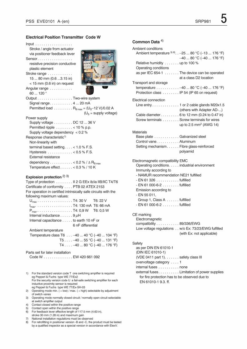
Electrical Position Transmitter Code W
Input . . . . . . . . . . . . . . . . . .Stroke / angle from actuatorvia positioner feedback lever
Sensor. . . . . . . . . . . . . . . . .resistive precision conductiveplastic element
Stroke range . . . . . . . . . . . .15 ... 80 mm (0.6 ...3.15 in)< 15 mm (0.6 in) on request
Angular range . . . . . . . . . . .60 ... 120 °
Output . . . . . . . . . . . . . . . . . Two-wire systemSignal range. . . . . . . . . . . 4 ... 20 mAPermitted load . . . . . . . . . RB max = (US–12 V)/0.02 A
(US = supply voltage)Power supply
Supply voltage . . . . . . . . . DC 12 ... 36 VPermitted ripple . . . . . . . . < 10 % p.p.Supply voltage dependency < 0.2 %
Response characteristic1)
Non-linearity withterminal based setting. . . . < 1.0 % F.S.Hysteresis . . . . . . . . . . . . < 0.5 % F.S.External resistancedependency . . . . . . . . . . . < 0.2 % / Δ RB max
Temperature effect . . . . . . < 0.3 % / 10 K
Explosion protection 2) 3)
Type of protection . . . . . . . . II 2 G EEx ib/ia IIB/IIC T4/T6Certificate of conformity . . . . PTB 02 ATEX 2153For operation in certified intrinsically safe circuits with thefollowing maximum values:
Umax . . . . . . . . . . . . . . . . . T4: 30 V T6: 22 VImax. . . . . . . . . . . . . . . . . . T4: 130 mA T6: 66 mAPmax.. . . . . . . . . . . . . . . . . T4: 0,9 W T6: 0,5 WInternal inductance . . . . . . 9 μHInternal capacitance . . . . . to earth 10 nF or
6 nF differentialAmbient temperatureTemperature class T6 . . . –40 ... 40 °C (–40 ... 104 °F)
T5 . . . . –40 ... 55 °C (–40 ... 131 °F)T4 . . . . –40 ... 80 °C (–40 ... 176 °F)
Parts set for later installationCode W . . . . . . . . . . . . . . EW 420 661 092
Common Data 4)
Ambient conditionsAmbient temperature 5) 6). . –25 ... 80 °C (–13 ... 176 °F)
–40 ... 80 °C (–40 ... 176 °F)Relative humidity . . . . . . . up to 100 %Operating conditionsas per IEC 654-1 . . . . . . . The device can be operated
at a class D2 locationTransport and storage
temperature . . . . . . . . . . . –40 ... 80 °C (–40 ... 176 °F)Protection class . . . . . . . . IP 54 (IP 65 on request)
Electrical connectionLine entry . . . . . . . . . . . . . 1 or 2 cable glands M20x1.5
(others with Adapter AD-...)Cable diameter. . . . . . . . . 6 to 12 mm (0.24 to 0.47 in)Screw terminals . . . . . . . . Screw terminals for wires
up to 2.5 mm2 (AWG 14)
MaterialsBase plate . . . . . . . . . . . . Galvanized steelControl vane. . . . . . . . . . . AluminumSetting mechanism. . . . . . Fibre glass-reinforced
polyamid
Electromagnetic compatibility EMCOperating conditions. . . . . industrial environmentImmunity according to- NAMUR recommendation NE21 fulfilled- EN 61 326 . . . . . . . . . . . fulfilled- EN 61 000-6-2 . . . . . . . . fulfilledEmission according to- EN 55 011,Group 1, Class A . . . . . . fulfilled
- EN 61 000-6-2 . . . . . . . . fulfilled
CE markingElectromagneticcompatibility . . . . . . . . . . . 89/336/EWGLow voltage regulations . . w/o Ex: 73/23/EWG fulfilled
(with Ex: not applicable)
Safetyas per DIN EN 61010-1(DIN IEC 61010-1)(VDE 0411 part 1). . . . . . . safety class IIIovervoltage category . . . . 1internal fuses . . . . . . . . . . noneexternal fuses. . . . . . . . . . Limitation of power supplies
for fire protection has to be observed due toEN 61010-1 9.3. ff.

MODEL CODES Accessories
MODEL CODES SRP981
6 SRP981 PSS EVE0101 A-(en)
Pneumatic Positioner SRP981 011009
VersionSingle Acting . . . . . . . . . . . . . . . . . . . . . . . . . -BDouble Acting. . . . . . . . . . . . . . . . . . . . . . . . . -C
InputSignal Range 0.2 to 1 bar/3 to 15 psi/ 20 - 100 kPa;
Split-Range Up To 4-Fold Possible, Must Be Specified . . . . . . . -IMode of Action
Increasing Input Increases Output . . . . . . . . . . . . . . . . . . . . . . DIncreasing Input Decreases Output . . . . . . . . . . . . . . . . . . . . . R
GaugesWithout Gauges. . . . . . . . . . . . . . . . . . . . . . . . . . . . . . . . . . . LTwo Built-In Gauges (bar/psi) . . . . . . . . . . . . . (a) . . . . . . . . . . . . . M
Built-In Limit Switch/Position TransmitterWithout . . . . . . . . . . . . . . . . . . . . . . . . . . . . . . . . . . . . . . . . . . SInductive Limit Switch Three-Wire Technique, Without Explosion Protection . (b). . . . . . RInductive Limit Switch (Standard Version) w. Expl. Prot. II 2 G EEx ia IIC T6 acc. to ATEX (b) . TInductive Limit Switch (Security Version) w. Expl. Prot. II 2 G EEx ia IIC T6 acc. to ATEX (b) . . UTwo Micro Switches, Without Explosion Protection. . . (b) . . . . . . . . . . . . . . . . VPosition Transmitter 4-20 mA, with Expl. Prot. II 2 G EEx ia IIC T6 acc. to ATEX . . (b) . . W
Cable EntryWithout Cable Gland . . . . . . . . . . . . . . . . . . . . . . . . . . . . . . . . . . . . . . . 1M20 x 1.5 With One Plastic Cable Gland, Color Gray . (c) . . . . . . . . . . . . . . . . . . . . 7
Attachment KitOrder as Auxiliary . . . . . . . . . . . . . . . . . . . . . . . . . . . . . . . . . . . . . . . . . . . . N
ManifoldOrder as Auxiliary . . . . . . . . . . . . . . . . . . . . . . . . . . . . . . . . . . . . . . . . . . . . . . . . A
OptionsAmplifier Free Of Nonferrous Metals . . . . . . . . . (a)(d) . . . . . . . . . . . . . . . . . . . . . . . . . . . . . . -CManual Bypass Switch . . . . . . . . . . . . . . . . (a). . . . . . . . . . . . . . . . . . . . . . . . . . . . . . . -TProtection Class IP65 . . . . . . . . . . . . . . . . . (b). . . . . . . . . . . . . . . . . . . . . . . . . . . . . . . -FAssembled Free Of Oil And Grease / Designed for Aux. Energy Oxygen . . . . . . . . . . . . . . . . . . . . . . . . -SLloyd's Register of Shipping . . . . . . . . . . . . . . . . . . . . . . . . . . . . . . . . . . . . . . . . . . . . . . -XCertificate EN 10204-2.1 - Certificate of compliance with the order . . . . . . . . . . . . . . . . . . . . . . . . . . . -1Tag No. LabelingStamped With Weather Resistant Color . . . . . . . . . . . . . . . . . . . . . . . . . . . . . . . . . . . . . . . . -GStainless Steel Label Fixed With Wire . . . . . . . . . . . . . . . . . . . . . . . . . . . . . . . . . . . . . . . . . -L
Example Model Code: SRP981 -B I D L S 1 N A -L
(a) Only available with Version -B(b) Not available with Gauge Code M or N(c) Not available with Built-In Limit Switch / Position Transmitter Code S(d) Not with Gauges M
Couple lever / cam EBZGStandard (a = 72 mm) (for SRP981, SRI983, SRI986, SMP981, SMI983, SGE985) . . . . . . . . . . . . . . . . . . -ANExtended (a = 91 mm) (for SRP981, SRI983, SRI986, SMP981, SMI983, SGE985) . . . . . . . . . . . . . . . . . . -BNInverse equal percentage cam for rotary actuators (for SRP981, SRI983, SRI986) . . . . . . . . . . . . . . . . . . . -CN
Spring set FESGRange-Springs (4 pc.) (for SRP981, SRI983, SRI986) . . . . . . . . . . . . . . . . . . . . . . . . . . . . . . . . . -FN
(continued on next page)

MODEL CODES Accessories (continued)
PSS EVE0101 A-(en) SRP981 7
Attachment kit EBZGFor diaphragm actuators with casting yoke acc. NAMUR. (incl. standard Couple Lever)
(for SRP981, SRI983, SMP981, SMI983, SGE985) . . . . . . . . . . . . . . . . . . . . . . . . . . . . . . . . . -GNFor diaphragm actuators with pillar yoke acc. NAMUR. (incl. standard Couple lever)
(for SRP981, SRI983, SMP981, SMI983, SGE985) . . . . . . . . . . . . . . . . . . . . . . . . . . . . . . . . . -FNFor rotary actuators, without flange, 3 drill holes 6.5 mm (for SRP981, SRI983, SRI986, SMP981, SMI983, SGE985) . -PNFor rotary actuators, without flange, 4 threads M6 (e.g for Petras actuators)
(for SRP981, SRI983, SRI986, SMP981, SMI983, SGE985). . . . . . . . . . . . . . . . . . . . . . . . . . . . . -NNFor rotary actuators, with flange (for SRP981, SRI983, SRI986, SMP981, SMI983, SGE985) . . . . . . . . . . . . . -JNFor rotary actuators acc. to VDI/VDE 3845, with shaft (for SRP981, SRI983, SRI986, SMP981, SMI983, SGE985). . . -ZNFor Masoneilan type Camflex II (for SRP981, SRI983, SRI986, SMP981, SMI983, SGE985). . . . . . . . . . . . . . -RNFor Masoneilan type Sigma F (for SRI986, SRP981, SRI983) . . . . . . . . . . . . . . . . . . . . . . . . . . . . . -SNFor Masoneilan type 37/38, Fisher Elliott type 656, 667 (for SRP981, SRI983, SGE985, SMI983, SMP981) . . . . . . -TNFor Gulde type P (for SRP981, SRI983) . . . . . . . . . . . . . . . . . . . . . . . . . . . . . . . . . . . . . . . . -UNFor Masoneilan type 87/88 (for SRP981, SRI983, SMP981, SMI983, SGE985) . . . . . . . . . . . . . . . . . . . . -ENFor Masoneilan VariPak (for SRP981, SRI983, SGE985, SMI983, SMP981). . . . . . . . . . . . . . . . . . . . . . -MNFor IAL actuators (for SRP981, SRI983, SGE985, SMI983, SMP981) . . . . . . . . . . . . . . . . . . . . . . . . . -VNBrackets VDI/VDE 3845 (A = 130 mm/5.12 in; B = 50 mm/1.97 in) (SRP981, SRI983, SRI986, SGE985, SMI983, SMP981) -C3Brackets VDI/VDE 3845 (A = 80 mm/3.15 in; B = 30 mm/1.18 in) (SRP981, SRI983, SRI986, SGE985, SMI983, SMP981). -C2Brackets VDI/VDE 3845 (A = 80 mm/3.15 in; B = 20 mm/0.79 in)�(SRP981, SRI983, SRI986, SGE985, SMI983, SMP981). -C1
Manifold (Connection 1/4-18NPT) LEXGStaggered connections (for SRP981, SRI986) . . . . . . . . . . . . . . . . . . . . . . . . . . . . . . . . . . . . . -BNConnections same level (for SRP981, SRI986) . . . . . . . . . . . . . . . . . . . . . . . . . . . . . . . . . . . . -CNStaggered connections for 1/4"-thread pneum. tube-conn. (e.g. tube-diameter: 8 mm / 0.3 in) (for SRP981, SRI986) . . -DNWith gauges for supply air, y, for version single acting (for SRP981, SRI986). . . . . . . . . . . . . . . . . . . . . . -JNWith gauges for supply air, w, for version single acting (for SRP981) . . . . . . . . . . . . . . . . . . . . . . . . . . -KNWith gauges for supply air, w, y, for version single acting (for SRP981). . . . . . . . . . . . . . . . . . . . . . . . . -LNWith gauges for supply air, y1, y2, for version double acting (for SRP981, SRI986) . . . . . . . . . . . . . . . . . . -MNWith gauges for w, y1, y2, for version double acting (for SRP981) . . . . . . . . . . . . . . . . . . . . . . . . . . . -NNGauge manifold without gauge (for SRP981, SRI986) . . . . . . . . . . . . . . . . . . . . . . . . . . . . . . . . . -RNGauge manifold without gauge, for supply air, y1, y2, for version double acting (for SRP981, SRI986) . . . . . . . . . -SNGauge manifold without gauge, for w, y1, y2, for version double acting (for SRP981) (b) . . . . . . . . . . . . . . . . -TN
Booster (Connection 1/4-18NPT) VKXGFor version single acting (for SRP981, SRI986) . . . . . . . . . . . . . . . . . . . . . . . . . . . . . . . . . . . . -FNFor version double acting (for SRP981, SRI986). . . . . . . . . . . . . . . . . . . . . . . . . . . . . . . . . . . . -GNFor version single acting with doubled output capacity (for SRP981, SRI986) . . . . . . . . . . . . . . . . . . . . . -HN

8 SRP981 PSS EVE0101 A-(en)
MODEL CODES Accessories (continued)
Adapter ADAdapter 1/2" NPT to 3/4" NPT (stainless steel) . . . . . . . . . . . . . . . . . . . . . . . . . . . . . . . . . . . . . -A3Adapter M20 x 1.5 to G1/2" (internal thread) (stainless steel) . . . . . . . . . . . . . . . . . . . . . . . . . . . . . . -A8Adapter M20 x 1.5 to 1/2" - 14 NPT (internal thread) (brass with nickel coating) . . . . . . . . . . . . . . . . . . . . -A5Adapter M20 x 1.5 to 1/2" - 14 NPT (internal thread) (stainless steel) . . . . . . . . . . . . . . . . . . . . . . . . . . -A6Adapter (plastic) M20 x 1.5 to PG13.5 (internal thread). . . . . . . . . . . . . . . . . . . . . . . . . . . . . . . . . -A9
Cable gland BUSGM20 x 1.5 plastics, color blue . . . . . . . . . . . . . . . . . . . . . . . . . . . . . . . . . . . . . . . . . . . . . -K7M20 x 1.5 plastics, color white . . . . . . . . . . . . . . . . . . . . . . . . . . . . . . . . . . . . . . . . . . . . . -K9M20 x 1.5 stainless steel. . . . . . . . . . . . . . . . . . . . . . . . . . . . . . . . . . . . . . . . . . . . . . . . -S6M20 x 1.5 plastics, color gray . . . . . . . . . . . . . . . . . . . . . . . . . . . . . . . . . . . . . . . . . . . . . -K6M20 x 1.5 stainless steel EEx d . . . . . . . . . . . . . . . . . . . . . . . . . . . . . . . . . . . . . . . . . . . . -S7M20 x 1.5 brass zink plated EEx d . . . . . . . . . . . . . . . . . . . . . . . . . . . . . . . . . . . . . . . . . . . -S81/2-14 NPT cable gland 6…12 mm, Stainless steel, EEx d . . . . . . . . . . . . . . . . . . . . . . . . . . . . . . -N11/2-14 NPT cable gland 6…12 mm, Steel zink plated, EEx d . . . . . . . . . . . . . . . . . . . . . . . . . . . . . -N21/2-14 NPT, brass zink plated, EEx d . . . . . . . . . . . . . . . . . . . . . . . . . . . . . . . . . . . . . . . . . -N3M20 x 1.5 plug, plastic . . . . . . . . . . . . . . . . . . . . . . . . . . . . . . . . . . . . . . . . . . . . . . . . . -V3M20 x 1.5 plug, Stainless steel, EEx d . . . . . . . . . . . . . . . . . . . . . . . . . . . . . . . . . . . . . . . . . -V41/2-14 NPT plug,Stainless Steel, EEx d . . . . . . . . . . . . . . . . . . . . . . . . . . . . . . . . . . . . . . . . -V5M20 x 1.5 plug, brass zink plated, EEx d . . . . . . . . . . . . . . . . . . . . . . . . . . . . . . . . . . . . . . . . -V61/2-14 NPT plug, brass zink plated, EEx d . . . . . . . . . . . . . . . . . . . . . . . . . . . . . . . . . . . . . . . -V7

mmin
71
2.80
4 .318
.16
9.3
5
30
80 3.15
9 .35
9
.35
21 .83
11 .43
52 2.05
116
4.5
743 1.6
971
2.8
0
8 .31
6,5
.26
54
2.13
49,5
1.9
5
722.83
43 1.69
963.78
M8
10.39
20 .78
7,9
.31
+0,2
+.0
1
6.24
833.27
722.83
14.55
2,5
.10
913.58
M6
10.39
65 2.56
71 2.8
0 54
2.13
43 1.6
9
20 ... 35
.79 ... 1.38
8
.3
2 pieces
Attachment to casting yokeaccording to IEC 534-6 (NAMUR)Code EBZG-GN
Attachment to pillar yokeaccording to IEC 534-6 (NAMUR)Code EBZG-FN
Mounting bracketaccording to IEC 534-6 (NAMUR)for Code EBZG-GN, FN
Feedback leverCode EBZG-AN, -FN, -GNCode EBZG-BN (extended version)
Corrier boltfor attachment to valve stem
PSS EVE0101 A-(en) SRP981 9ATTACHMENT KIT FOR DIAPHRAGM ACTUATORS

mmin
5 .20
70 2.76
3 .12
5.04
(6.4
6*)
128
(164
*)
10 .39
6
47
54
63
86
.241.85
2.13
2.48
3.39
120
M6
M6
M6
4,5
.18
4.16
8 .31
13,5.53
14.55
6.53
3.46
(4.8
8*)
88 (1
24*)
30 1.18
28+0
,5
1.10
+.02 99 3.
90
431.69
953.74
501.97
16H
8.6
3
12 .47
64 2.52
1676.57
3.46
(4.8
8*)
88 (1
24*)
1,2
.05
16.63
11.43
14 ... 15,5 .55 ... .61
.59
.01
12 .47
150,
2
12 .47
1676.57
64 2.52
99 3.90
1.77 .0145 0,2
431.69
953.74
6,5.26
14 - 6 tief.55 - .24 deep/
22 .87
1676.57
12 .47
99 3.9
6,5
.26
501.97
10 .39
60 2.36
0,2 .01
75 2.95
0,2 .01
M6 x 14 (2x)DIN 912
M6 x 14 (2x)DIN 912
M6 x 14 (2x)DIN 912
*) with gauges (Option)
With shaft(according to VDI/VDE 3845)Code EBZG-ZN
Detail Z
Detail Y
With flangeCode EBZG-JN
Without flangeCode EBZG-NN, -PN
Housing dimensionsAttachment kit with shaft resp. without flangeCode EBZG-NN
Housing dimensionsAttachment kit without flangeCode EBZG-PN
Rotation angle max 120˚; torque requirement 14 Nm
Adaption of the actuator drive shaft endand correct axial location by client !
10 SRP981 PSS EVE0101 A-(en)
ATTACHMENT KIT FOR ROTARY ACTUATORS

PSS EVE0101 A-(en) SRP981 11DIMENSIONS Additional equipment
Connection manifold, staggered connectionsCode LEXG-BN
Booster single actingCode VKXG-FN
Connection manifold, connections same levelCode LEXG-CN
Booster single acting with doubled output capacityCode VKXG-HN
1 23 6
913.58
65,
52.5
8
3.4688
1 25 6
1044.09
87 3.43
1084.25
1 234 6
104
4.09
83
3.27
85 3.35
Booster double actingCode VKXG-GN
1 234
6
301.18
883.46
28,5
1.1
2
1 23
6
4
88
3.46
30
1.1828
,5
1.12
� �� �
1 Female thread 1/4-18 NPT for supply air2 Female thread 1/4-18 NPT for input (w)3 Female thread 1/4-18 NPT for output I (y1)4 Female thread 1/4-18 NPT for output II (y2)5 Female thread 1/2-14 NPT for output I (y1)6 Fixing screws 17 mm A/F

12 SRP981 PSS EVE0101 A-(en)
DIMENSIONS Additional equipment
Built-in limit switch Code R, T, U, V
Built-in position transmitter Code W
Connection manifold with gauges Code LEXG-JN, -KN, -LN, -MN, -NNConnection manifold for gauges Code LEXG-RN, -TN, -SN
963.78
21
3
� �� �
� �
�
�
�
� � �
752.95
53,5
2.11
102
4.02
1 24 38 9
6
7
� �� �
1 Female thread 1/4-18 NPT for supply air2 Female thread 1/4-18 NPT for input (w)3 Female thread 1/4-18 NPT for output I (y1)4 Female thread 1/4-18 NPT for output II (y2)
(only on manifold Code M, N)
6 Fixing screws 17 mm A/F
1 Cable gland2 Dummy plug can be replaced with 13 Connection terminals
Built-in limit switch CodeT, U R V
1 Cable gland2 Dummy plug can be replaced with 13 Connection terminals (+/–)4 Ground connection
� � �
� �
�
�
�
� �
� � � � � �
� �
�
�
� �
� �
� �
� �
� � � � � �
� �
�
�
� �
� �
�
�
�
�
�
�
ManifoldCode LEXG
7Gauge for
8Gauge for
9Gauge for
Version
Action
-JN (-RN*) without output (y) supply air single
-KN (-RN*) input (w) without supply air single
-LN (-RN*) input (w) output (y) supply air single
-MN (-SN*) supply air output I (y1) output II (y2) double
-NN (-TN*) input (w) output I (y1) output II (y2) double
*) Connection manifold for gauges, without gauges(for customer’s gauges)

PSS EVE0101 A-(en) SRP981 13DIMENSIONS SRP981 Special version in Stainless Steel Housing
���
����
� � � �� � � �
� � � � �
� �� � �
���
���
��
�� �
� � � � �
� �� � � �

� �
� �
� �
� � � �
�
�� � �
� �
� �
� �
� � � �� � � �
���
���
� � �� � �
�
�� �
� � � � � � �
� � � � � � � � � � � �
� �
� �
� �
�
����
������
����� �
����
� � � � � � � � � �
� � �
�
14 SRP981 PSS EVE0101 A-(en)
Further Product Specification Sheets:
PSS EVE0101A-(de) SRP981 Pneumatic PositionerPSS EVE0102A-(de) SRI986 Electro-Pneumatic PositionerPSS EVE0103A-(de) SRI983 Electro-Pneumatic Positioner - explosion proof or EEx d versionPSS EVE0105A-(de) SRD991 Intelligent PositionerPSS EVE0107A-(de) SRI990 Analog PositionerPSS EVE0109A-(de) SRD960 Universal Positioner
1 Female thread G 1/8 for output II (y2)(only on double-acting positioner)
2 Female thread G 1/8 for supply air3 Female thread G 1/8 for output I (y1)4 Female thread G 1/8 for input (w)
9 Feedback lever
10 Gauge* for input11 Gauge* for output
* with gauges (optional, only on single-acting positioner)
Front viewCode L Code M, N
Subject to alterations - reprinting, copying and translation prohibited. Products and publications are normallyquoted here without reference to existing patents, registered utility models or trademarks. The lack of any suchreference does not justify the assumption that a product or symbol is free.
FOXBORO ECKARDT GmbHPostfach 50 03 47D-70333 StuttgartTel. # 49(0)711 502-0Fax # 49(0)711 502-597http://www.foxboro-eckardt.com DOKT 535 780 021
DIMENSIONS, CONNECTIONS