Embed Size (px)
Citation preview

191 [email protected] Revision: 30-SEP-2016
Quality • Reliability
Cost-Down via Innovation.Quality • Reliability
Cost-Down via Innovation.
Specifications Per • IEC 60115-1
Features• IEC60065 & UL1676 Compliant• MELF packaging yet capable of high power handling• Special conductive film enhances anti-surge capability.• Absorbs harmful surge which damages precious devicesor components.
• SMD-enabled alternative to carbon composition resistors• Approved to the safety requirement of VDE0860under license number 40043961
• Products meet RoHS requirements and do not containsubstances of very high concern identified by EuropeanChemicals Agency
Dimensions
Type Body Length(L, mm)
Cap Diameter(D1, mm)
Body Diameter(D2, mm)
Soldering Spot(B, mm)
Net WeightPer 1000 pcs
SRM204 3.52 ± 0.15 1.35 ± 0.1 D1+0.02/ -0.15 0.6 Min. 17 gramsSRM204T 3.52 ± 0.15 1.35 ± 0.1 D1+0.02/ -0.15 0.6 Min. 17 gramsSRM207 5.90 ± 0.20 2.20 ± 0.1 D1+0.02/ -0.2 1.0 Min. 66 grams
SRM207P 5.90 ± 0.20 2.20 ± 0.1 D1+0.02/ -0.2 1.0 Min. 66 gramsSRM101 5.90 ± 0.20 2.20 ± 0.1 D1+0.02/ -0.2 1.0 Min. 66 grams
SRM101T 5.90 ± 0.20 2.20 ± 0.1 D1+0.02/ -0.2 1.0 Min. 66 gramsSRM201 8.50 ± 0.50 3.00 ± 0.2 D1+0.05/ -0.35 1.3 Min. 186 gramsSRM301 10.5 ± 0.50 4.00 ± 0.5 D1+0.05/ -0.45 1.6 Min. 446 grams
General SPeciFicationS
TypePowerRating
( at 70°C )
MaximumWorkingVoltage
MaximumPermissible
Surge VoltageMinimum
Resistance Maximum
ResistanceResistanceTolerance
AvailableResistance
ValuesSRM204 1/4W 400V 2,000V 1Ω 1MΩ ±1%~±5% E-24/E-96
SRM204T 1/2W 450V 4,000V 1Ω 10MΩ ±1%~±5% E-24/E-96SRM207 1/2W 600V 6,000V 1Ω 2M2Ω ±1%~±5% E-24/E-96
SRM207P 1/2W 600V 8,000 V 0.1Ω 2M2Ω ±1%~±5% E-24/E-96SRM101 1W 600V 8,000 V 0.1Ω 2M2Ω ±1%~±5% E-24/E-96SRM101T 1W 600V 10,000 V 0.1Ω 2M2Ω ±1%~±5% E-24/E-96SRM201 2W 700V 9,000V 0.1Ω 2M2Ω ±1%~±5% E-24/E-96SRM301 3W 800V 10,000V 0.1Ω 2M2Ω ±1%~±5% E-24/E-96
Special sizes, values, and specifications not listed available on special order.For resistance values outside the specified ranges, please contact us.
B
L D1
D2
sRm
SRMSurge Resistant MELF Resistor
VDEREG.-Nr. A830
VDEREG.-Nr. E932

[email protected]: 30-SEP-2016
Quality • Reliability
Cost-Down via Innovation.Quality • Reliability
Cost-Down via Innovation.
SRMSurge Resistant MELF Resistor
Power DeratinG curve
technical Summary
Characteristics Ranges & Limits
Dielectric Withstanding Voltage, VAC or DC
SRM204TSRM204/207/207P/101SRM201/101TSRM301
300350500800
Temperature Coefficient, PPM / °C* ±100, ±200, ±400Operating Temperature Range, °C -55 ~ +150Insulation Resistance, MΩ >104
Tin Whisker (JESD201 Temperature Cycling & High Temp. /Humidity Storage), μm <5
sRm
* not applicable to all resistance values. Please check with us regarding the PPm of specific resistance value(s).
AMBIENT TEMPERATURE (oC)
RATE
DLO
AD
F 16R2 TKZ
* listed values may not be applicable across product types or to all resistance values. Please check with us before placing order.** For the availabilities of non-default temperature coefficient, please check with us. reference for tcr letter codes can be found in section (4) of Part number construction in the appendices.*** upon request
part nUmBer Example: SRM204TF16R2TKZTR3K0
Type Tolerance*
F (1%)J (5%)
Resistance
16.2Ω4-character code
containing -3 significant digits 1 letter multiplier
MULTIPLIER R = 1
K = 103 M = 106 G = 109
TCR
3-character code
TKZ = Default Product Temperature Coefficient.
Information of typical product temperature
coefficient can be found in the Technical Summary section of the datasheet.**
Packaging
5-character code
TR = Tape Reel
(pieces per reel) SRM204/SRM204T
3K0 = 3,0006K0 = 6,000***10K = 10,000***
SRM207/SRM207PSRM101/SRM101T
2K0 = 2,0006K0 = 6,000***
10K = 10,000***
SRM2012K5 = 2,500
SRM3012K0 = 2,000
SRM204T TR3K0

193 [email protected] Revision: 30-SEP-2016
Quality • Reliability
Cost-Down via Innovation.Quality • Reliability
Cost-Down via Innovation.
SRMSurge Resistant MELF Resistor
PerFormance SPeciFicationS
Test Characteristics Test Conditions Limits
Short Time Overload IEC 60115-1 4.135 seconds 2.5x rated voltage (not over max. working voltage) ±2%
Load Life In HumidityIEC 60115-1 4.2456 days rated load (not over max. working voltage) at (40±2)°C and (93±3)% relative humidity
±5%
Load Life 1,000 hoursIEC 60115-1 4.25.1Rated load (not over max. working voltage) with 1.5 hours ON, 0.5 hours OFF, at (70±2)°C
±5%
Periodic Electric OverloadIEC 60115-1 4.393.9x rated voltage (not over 2X max. working voltage) with 0.1s ON, 2.5s OFF for 1,000 cycles
±1%
Resistance To Soldering HeatIEC 60115-1 4.18.2Dip the resistor into a solder bath measured (260±5)°C and hold it for a 10±1 seconds
±1%
Solderability IEC 60115-1 4.17.2Solder area covered after (235±3)°C/(2±0.2) seconds with flux applied 95% Min.
VibrationIEC 60015-1 4.22Six hours in each parallel and axial direction with a simple harmonic motion having an amplitude of 0.75mm and 10 to 500 Hz.
±1%
Thermal Endurance IEC 60115-1 4.25.31000 hours at 150°C without load ±1%
Thermal Shock IEC 60115-1 4.19-55°C 30minutes, +150°C 30minutes, 5 cycles ±2%
Single pulse high voltage overload
IEC 60115-1 4.27 10 pulses of 10/700μs at 10x rated voltage (not over 2x max. working voltage) with interval of 60 sec.
±1.0%
Electrostatic discharge(Human body model)
IEC 60115-1 4.383 positive & 3 negative discharges with 4KV source ±1%
Climatic test
IEC 60115-1 4.234.23.2 - dry heat: 16 hours 150°C4.23.3 - damp heat: 24 hours 55°C with 95% relative humidity4.23.4 - cold: 2 hours -55°C4.23.5 - negative air pressure: 2 hour 8.5KPa at (25±10)°C4.23.6 - damp heat cyclic: 5 days 55°C with 95% relative humidity4.23.7 - DC load: rated voltage at -55°C and 150°C each 1 Min.
±2%
Bending test IEC 60115-1 4.33Pressing depth 2mm, 3 times ±1%
Flammability IEC 60115-1 4.35Needle flame test 10s No burning after 30s
Surge Test
Propietary test specification FRC-TR-010113 = (6000 x P x R) DC P is power rating, R is resistance value, surge voltage is not more than listed at rightSurge spec = 1.2/50μsPeriod = 12 secNumber of surges = 5
SRM204 2KV
±5%
SRM204T 4KVSRM207 6KVSRM101/207P 8KVSRM201 9KVSRM301/101T 10KV
sRm

[email protected]: 30-SEP-2016
Quality • Reliability
Cost-Down via Innovation.Quality • Reliability
Cost-Down via Innovation.
SRMSurge Resistant MELF Resistor
PEA
K P
OW
ER
(w
att)
PEA
K P
OW
ER
(w
att)
PEA
K P
OW
ER
(w
att)
0.00001s 0.0001s 0.001s 0.01s 0.1s 1s
100
10
1
1000
10μs μs100 1ms 10ms 100ms 1s
SURGE DURATION
SRM201
PEA
K P
OW
ER
(w
att)
0.00001s 0.0001s 0.001s 0.01s 0.1s 1s
100
10
1
1000
10000
10μs μs100 1ms 10ms 100ms 1s
SURGE DURATION
SRM301
PEA
K P
OW
ER
(w
att)
0.00001s 0.0001s 0.001s 0.01s 0.1s 1s
100
10
1
10μs μs100 1ms 10ms 100ms 1s
SURGE DURATION
SRM101
PEA
K P
OW
ER
(w
att)
0.00001s 0.0001s 0.001s 0.01s 0.1s 1s
100
10
1
10μs μs100 1ms 10ms 100ms 1s
SURGE DURATION
SRM204T
0.00001s 0.0001s 0.001s 0.01s 0.1s 1s
100
10
1
1000
1000
10μs μs100 1ms 10ms 100ms 1s
SURGE DURATION
SRM207
0.00001s 0.0001s 0.001s 0.01s 0.1s 1s
100
10
1
10μs μs100 1ms 10ms 100ms 1s
SURGE DURATION
SRM204
SURGE DURATION
SRM207P
PEA
K P
OW
ER
(w
att)
0.00001s 0.0001s 0.001s 0.01s 0.1s 1s
100
10
1
1000
10000
PEA
K P
OW
ER
(w
att) 100
10
1
1000
10000
10μs μs100 1ms 10ms 100ms 1s
SRM101T
SURGE DURATION
0.00001s 0.0001s 0.001s 0.01s 0.1s 1s10μs μs100 1ms 10ms 100ms 1s
SinGle SurGe PerFormance
sRm
195 [email protected] Revision: 30-SEP-2016
Quality • Reliability
Cost-Down via Innovation.Quality • Reliability
Cost-Down via Innovation.
PEA
K P
OW
ER
(w
att)
PEA
K P
OW
ER
(w
att)
PEA
K P
OW
ER
(w
att)
0.00001s 0.0001s 0.001s 0.01s 0.1s 1s
100
10
1
1000
10μs μs100 1ms 10ms 100ms 1s
SURGE DURATION
SRM201
PEA
K P
OW
ER
(w
att)
0.00001s 0.0001s 0.001s 0.01s 0.1s 1s
100
10
1
1000
10000
10μs μs100 1ms 10ms 100ms 1s
SURGE DURATION
SRM301
PEA
K P
OW
ER
(w
att)
0.00001s 0.0001s 0.001s 0.01s 0.1s 1s
100
10
1
10μs μs100 1ms 10ms 100ms 1s
SURGE DURATION
SRM101
PEA
K P
OW
ER
(w
att)
0.00001s 0.0001s 0.001s 0.01s 0.1s 1s
100
10
1
10μs μs100 1ms 10ms 100ms 1s
SURGE DURATION
SRM204T
0.00001s 0.0001s 0.001s 0.01s 0.1s 1s
100
10
1
1000
1000
10μs μs100 1ms 10ms 100ms 1s
SURGE DURATION
SRM207
0.00001s 0.0001s 0.001s 0.01s 0.1s 1s
100
10
1
10μs μs100 1ms 10ms 100ms 1s
SURGE DURATION
SRM204
SURGE DURATION
SRM207P
PEA
K P
OW
ER
(w
att)
0.00001s 0.0001s 0.001s 0.01s 0.1s 1s
100
10
1
1000
10000
PEA
K P
OW
ER
(w
att) 100
10
1
1000
10000
10μs μs100 1ms 10ms 100ms 1s
SRM101T
SURGE DURATION
0.00001s 0.0001s 0.001s 0.01s 0.1s 1s10μs μs100 1ms 10ms 100ms 1s
SinGle SurGe PerFormance
SRMSurge Resistant MELF Resistor
sRm
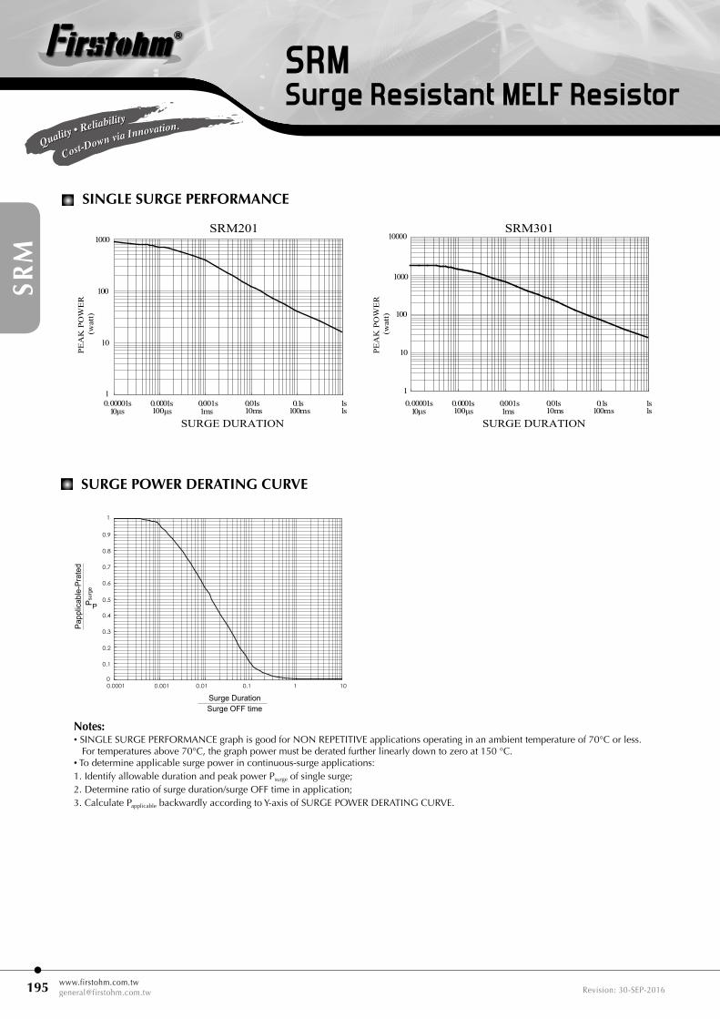
SurGe Power DeratinG curve
PEAK POWER (watt)
0.00001s 0.0001s 0.001s 0.01s 0.1s 1s
100
10
1
1 0 µs 1 00 µs 1m s 1 0 m s 1 00 m s 1 s
0.1
Surge Duration
P
0.0001 0.001 0.01 0.1 1 100
0.1
0.2
0.3
0.4
0.5
0.6
0.7
0.8
0.9
1
Papp
licab
le-P
rate
dP s
urge
Peak
Pow
er (w
att)
Surge DurationSurge OFF time
MMP52V
MMP204V
notes:• SINGLE SURGE PERFORMANCE graph is good for NON REPETITIVE applications operating in an ambient temperature of 70°C or less.
For temperatures above 70°C, the graph power must be derated further linearly down to zero at 150 °C.• To determine applicable surge power in continuous-surge applications:1. Identify allowable duration and peak power Psurge of single surge;2. Determine ratio of surge duration/surge OFF time in application;3. Calculate Papplicable backwardly according to Y-axis of SURGE POWER DERATING CURVE.

[email protected]: 30-SEP-2016
Quality • Reliability
Cost-Down via Innovation.Quality • Reliability
Cost-Down via Innovation.
SRMSurge Resistant MELF Resistor
Recommended peeling force: SRM204, SRM204T, SRM207, SRM207P, SRM101, SRM101T: 50±5gf SRM201, SRM301: 70±10gf
Type Soldering Mode Pad Length(L, mm, Min.)
Pad Spacing(P, mm)
Pad Width(W, mm, Min.)
SRM204/SRM204TReflow 1.3 1.6 ± 0.1 1.6Wave 1.5 1.5 ± 0.1 1.8
SRM207/207PReflow 2.0 3.0 ± 0.1 3.0Wave 2.5 3.0 ± 0.1 3.0
SRM101/101TReflow 2.0 3.0 ± 0.1 3.0Wave 2.5 3.0 ± 0.1 3.0
SRM201Reflow 3.0 4.9 ± 0.3 3.7Wave 3.5 4.8 ± 0.3 4.0
SRM301Reflow 4.0 6.2 ± 0.4 5.0Wave 4.5 6.0 ± 0.4 5.0
For better heat dissipation / lower heat resistance, increase w & l.
SuGGeSteD PaD layout
cover taPe PeelinG SPeciFication sR
m