Embed Size (px)
Citation preview

SRM-10X10-CHANNEL STEREO MIC/LINE MIXER
O W N E R ’ S M A N U A LM
IXE
R

2
SRM-10X10-Channel Stereo Mic/Line Mixer
Congratulations on your choice of mixers — you havepurchased one of the finest compact mixing consoles on themarket today. This unit was developed using the expertise ofprofessional sound engineers and working musicians. Youwill find that your new NADY AUDIO SRM-10X has superiorperformance and greater flexibility than any other mixer in itsprice range. Please read this manual carefully to get themost out of your new unit.
Thanks for selecting NADY AUDIO as your choice in mixingconsoles.
Date of Purchase
Dealer’s Name
City
State
Zip
Model #
Serial #
CONTENTSWARNING ..........................................................................................................................................................3
FEATURES ...................................................................................................................................................... 4
INSTALLATION.................................................................................................................................................. 51. Inspection ...................................................................................................................................................... 52. Power Connection .......................................................................................................................................... 5
CONTROLS AND CONNECTIONS .................................................................................................................. 61. Mono Input Section ........................................................................................................................................62. Stereo Input Section ........................................................................................................................................83. Master Section ................................................................................................................................................9
a. Aux Sends/Returns Function and Operation .......................................................................................... 9b. Main Mix Function and Operation ............................................................................................................9c. Monitor Function and Operation ............................................................................................................10d. Power Switches ......................................................................................................................................10
4. Connections..................................................................................................................................................11
SPECIFICATIONS............................................................................................................................................ 12
BLOCK DIAGRAM ..........................................................................................................................................13
NOTES ..............................................................................................................................................................14

WARNING
3
IMPORTANT SAFETY INSTRUCTIONS
When using this electronic device, basic precautions should always be taken, including the following: 1. Read all instructions before using the product.2. Do not use this product near water (e.g., near a bathtub, washbowl, kitchen sink, in a wet basement, or near a
swimming pool, etc.).3. This product should be used only with a cart or stand that will keep it level and stable and prevent wobbling.4. This product, in combination with headphones or speakers, may be capable of producing sound levels that
could cause permanent hearing loss. Do not operate for a long period of time at a high volume level or at a level that is uncomfortable. If you experience any hearing loss or ringing in the ears, you should consult an audiologist.
5. The product should be positioned so that proper ventilation is maintained.6. The product should be located away from heat sources such as radiators, heat vents, or other devices
(including amplifiers) that produce heat.7. The product should be connected to a power supply only of the type described in the operating instructions or
as marked on the product. Replace the fuse only with one of the specified type, size, and correct rating.8. The power supply cord should: (1) be undamaged, (2) never share an outlet or extension cord with other
devices so that the outlet’s or extension cord’s power rating is exceeded, and (3) never be left plugged into the outlet when not being used for a long period of time.
9. Care should be taken so that objects do not fall into, and liquids are not spilled through, the enclosure’ s openings.
10. The product should be serviced by qualified service personnel if:A. The power supply cord or the plug has been damaged. B. Objects have fallen into, or liquid has been spilled onto the product.C. The product has been exposed to rain. D. The product does not appear to operate normally or exhibits a marked change in performance.E. The product has been dropped, or the enclosure damaged.
11. Do not attempt to service the product beyond what is described in the user maintenance instructions. All other servicing should be referred to qualified service personnel.
ATTENTION: RISQUE DE CHOC ELECTRIQUE NE PAS OUVRIR
An equilateral triangle enclosing a lightening flash/arrowhead symbol is intended to alert the user to the presence of uninsulated “dangerous voltage” within the product’s enclosure which may be of sufficient magnitude to constitute a risk of electric shock.
An equilateral triangle enclosing an exclamation point is intended to alert the user to the presence of important operating and service instructions in the literature enclosed with this unit.
FEATURES
4
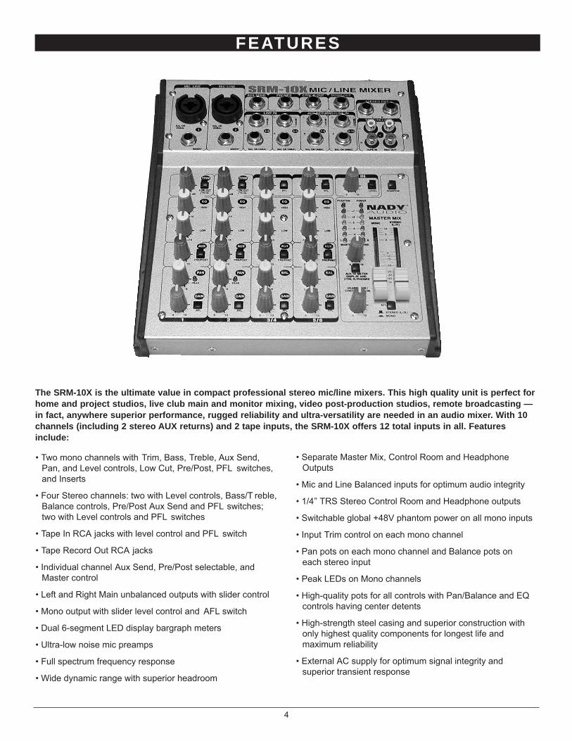
The SRM-10X is the ultimate value in compact professional stereo mic/line mixers. This high quality unit is perfect forhome and project studios, live club main and monitor mixing, video post-production studios, remote broadcasting —in fact, anywhere superior performance, rugged reliability and ultra-versatility are needed in an audio mixer. With 10channels (including 2 stereo AUX returns) and 2 tape inputs, the SRM-10X offers 12 total inputs in all. Featuresinclude:
• Two mono channels with Trim, Bass, Treble, Aux Send,Pan, and Level controls, Low Cut, Pre/Post, PFL switches,and Inserts
• Four Stereo channels: two with Level controls, Bass/T reble,Balance controls, Pre/Post Aux Send and PFL switches;two with Level controls and PFL switches
• Tape In RCA jacks with level control and PFL switch
• Tape Record Out RCA jacks
• Individual channel Aux Send, Pre/Post selectable, andMaster control
• Left and Right Main unbalanced outputs with slider control
• Mono output with slider level control and AFL switch
• Dual 6-segment LED display bargraph meters
• Ultra-low noise mic preamps
• Full spectrum frequency response
• Wide dynamic range with superior headroom
• Separate Master Mix, Control Room and HeadphoneOutputs
• Mic and Line Balanced inputs for optimum audio integrity
• 1/4” TRS Stereo Control Room and Headphone outputs
• Switchable global +48V phantom power on all mono inputs
• Input Trim control on each mono channel
• Pan pots on each mono channel and Balance pots oneach stereo input
• Peak LEDs on Mono channels
• High-quality pots for all controls with Pan/Balance and EQcontrols having center detents
• High-strength steel casing and superior construction withonly highest quality components for longest life andmaximum reliability
• External AC supply for optimum signal integrity andsuperior transient response
5
INSTALLATION
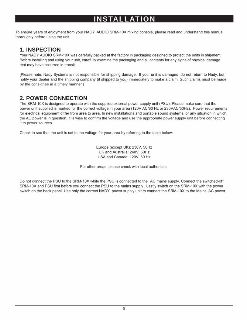
To ensure years of enjoyment from your NADY AUDIO SRM-10X mixing console, please read and understand this manualthoroughly before using the unit.
1. INSPECTIONYour NADY AUDIO SRM-10X was carefully packed at the factory in packaging designed to protect the units in shipment.Before installing and using your unit, carefully examine the packaging and all contents for any signs of physical damagethat may have occurred in transit.
[Please note: Nady Systems is not responsible for shipping damage. If your unit is damaged, do not return to Nady, butnotify your dealer and the shipping company (if shipped to you) immediately to make a claim. Such claims must be madeby the consignee in a timely manner.]
2. POWER CONNECTIONThe SRM-10X is designed to operate with the supplied external power supply unit (PSU). Please make sure that thepower unit supplied is marked for the correct voltage in your area (120V AC/60 Hz or 230VAC/50Hz). Power requirementsfor electrical equipment differ from area to area. In new installations and portable sound systems, or any situation in whichthe AC power is in question, it is wise to confirm the voltage and use the appropriate power supply unit before connectingit to power sources.
Check to see that the unit is set to the voltage for your area by referring to the table below:
Europe (except UK): 230V, 50HzUK and Australia: 240V, 50Hz
USA and Canada: 120V, 60 Hz
For other areas, please check with local authorities.
Do not connect the PSU to the SRM-10X while the PSU is connected to the AC mains supply. Connect the switched-offSRM-10X and PSU first before you connect the PSU to the mains supply . Lastly switch on the SRM-10X with the powerswitch on the back panel. Use only the correct NADY power supply unit to connect the SRM-10X to the Mains AC power.

CONTROLS AND CONNECTIONS
6
1. MONO INPUT SECTION
(1) COMBINED MIC XLR / 1/4” LINE INPUTThe Mic input is an electronically balanced XLR typedesigned to accept signals from any balanced low impedance(Low Z) microphone. To accommodate condensermicrophones, this input is also equipped with +48VDCphantom power globally switchable to all XLR input jacks withthe Phantom Power switch (33). Dynamic or ribbon-typemicrophones do not require phantom powering. It will benecessary to adjust the channel gain with the input Trimcontrol (3) to achieve a nominal operating level. The XLRjack is configured for: Pin1 = ground, Pin2 = positive (+), Pin3= negative (-).
[Note: The Mic inputs are more sensitive than the Line inputs.Also, do not connect mics with the phantom power switchedon, as indicated by the Phantom Power On LED (34) in theMaster Section of the front panel. Never use unbalanced miccables with the Phantom Power switched on. Never short the+48VDC to ground, as that can cause serious damage toyour mixer. Also, mute the Monitor/PA speakers when turningthe phantom power on or off.]
The 1/4” Line input is designed to accept balanced orunbalanced line-level signals such as those from keyboards,drum machines, or samplers. There is enough gain availableon the line input to accept even lower level signals, such asthose from an unbalanced microphone or guitar output. Usethe Trim control (3) to adjust for the desired level. If abalanced signal is to be connected to the line input, then a1/4" TRS (stereo) phone plug should be wired for: Tip =positive (+), Ring = negative (-), Sleeve = ground.
(2) INSERTSChannels 1 and 2 are equipped with insert jacks to connectexternal signal processors, such as compressors, noisereduction systems, or effects devices, to the individual inputchannels. Insert points are useful for adding dynamicprocessing or equalization to a channel. The signal isintercepted post Trim and pre EQ, fed through the externaldevice, then returned to the console at the same point whereit left. The insert point is normalized, i.e., the signal is onlyinterrupted when a connector is plugged into it. The insertjack is configured as: Tip = send, Ring = return, Sleeve =ground.
(3) TRIM CONTROLThe trim control adjusts the input sensitivity (channel gain) ofthe mic and line inputs on the mono input channels. Thiscontrol can be adjusted to accommodate input signals from awide variety of sources, from the high outputs from keyboardsor drum machines to the small signal outputs of microphones.This wide range eliminates the need for Mic/Line switching.
(1)
(2)
(5)
(6)
(8)
(10)
(9)
(4)(3)
(7)
(11)

CONTROLS AND CONNECTIONS
The best balance of S/N and dynamic range will be achievedif you adjust the TRIM control on each channel separately sothat the Peak Indicator LED (9) for that channel lightsoccasionally.
(4) LOW CUT FILTERUse this Low-Cut (high-pass) filter (18 dB/octave, -3 dB at 75Hz) for reducing floor rumble, popping, breathing noises,woolly bottom end, and to tighten up channels in a mix, etc. Itis most effective when used carefully in conjunction with theEqualizer Controls (5).
(5) EQUALIZER CONTROLSAll mono input channels are fitted with a two-band EQ. AllEQs have up to 15 dB of cut and boost, with a center detentfor "off". The frequency response is flat when EQ knobs are inthe center detent position. The upper and lower shelvingcontrols have their frequencies fixed at 12 kHz and 80 Hzrespectively. Remember that the Low Cut filter (4) is anintegral part of the overall equalization of a mono channel.The channel EQ is a valuable feature of the mixer as it allowsthe user to control the tonal characteristics of each instrumentseparately. For example, boosting the LOW can fatten thesound and add punch to the bass or drums and adjusting theHIGH control can provide a crisp sounding high end. With theLOW set to boost, and the Low Cut switch activated, you getpeak response rather than shelving at the bottom end. This isuseful for adding warmth to vocals and instruments, and goodfor tight but deep bass (without losing control of yoursubwoofer speaker cones). Another very important, yet oftenoverlooked technique is to use the EQ to subtract from themix. Cutting the HIGH control can reduce unwanted hissduring multi-track recording, while attenuating the LOW caneliminate feedback in a live performance or clear up a muddysounding mix. Cutting away the top and bottom, then pushingup the Gain is equivalent to mid range boost!
[Note: Always reset a channel’s input Gain (or externaldevices’ output level) after altering the amount of mixerequalization cut or boost applied.]
The key to successful equalization is to avoid excess. Toomuch equalization on the input channels will result in a mixthat is smeared together with nothing specifically defined.During rehearsals, experiment with the equalizer controls onvarious instruments, vocals and combinations of these mixedtogether to become familiar with various equalizer settings.
(6) AUX SEND CONTROLS The Channel AUX SEND is selectable Pre or Post Gaincontrol. For almost all ef fects send purposes, you will want touse the Post Gain selection, so that when a Gain level isadjusted, any reverb send from that channel will follow thefader. Otherwise, when the fader is pulled down, the reverbfrom that channel will still be audible.
(7) PRE/POST SWITCHThis switch selects whether the AUX SEND signal is Pre orPost Gain control. (Up = Pre, Depressed = Post)
(8) PAN CONTROLThe Channel Pan positions the output of the channel in thestereo field of the Master Mix. Its constant-power designensures there are no level discrepancies whether a signal ishard-panned, center-stage, or somewhere in-between.
(9) PEAK LED INDICATORThe Peak LED illuminates when a channel is going intooverload. It detects the peak level after the EQ and will lightat 3dB before clipping to warn that the signal is approachingoverload. You do not want the Peak LED to light except veryintermittently during a take or a mix. If it does lightpersistently, reduce input gain with the TRIM control (4).
(10) CHANNEL GAIN CONTROLThe channel gain controls determine the output signal level tothe Master Mix bus.
(11 & 13) PFL SWITCHChannels 1-10 and TAPE IN channels all have PFL (Pre-Fader Listen). This allows the Meter Display and CONTROLROOM/HEADPHONE outputs to monitor channel signals Prechannel Gain controls.
[Note: When the PFL buttons are depressed, the AUX ToMeter switch should be in the off (up) position]
7

CONTROLS AND CONNECTIONS
8
2. STEREO INPUT SECTION
(12)
(18)
(14)
(13)
(17)
(16)
(19)
(15)
(24) L (MONO) LINE INPUTOn stereo input channels 3-6, the 1/4" line inputs aredesigned for stereo or mono line-level signals such as thosefrom keyboards, drum machines, CD players, tape decks, orsamplers. However, these inputs can also be used asstandard mono line inputs by connecting the signal to the L(MONO) line in. This signal will be routed equally to the BALcontrol and the left and right outputs in the same way as themono input channels. For the stereo inputs, the mono channelPAN (8) control is replaced by the BAL (Balance) control. Seealso BAL Control (17) below.
(25) R LINE INPUTWhen using channels 3-6 as stereo input channels, the leftsignal should be connected to the L input and the right signalto the R input. These signals will be routed to the AUX, EQand Channel Gain controls equally and will retain their stereoseparation. The AUX, EQ, BAL, and Channel Gain controlsall function the same as those on the mono input channels.When a stereo signal is input to a stereo input channel, thesecontrols will affect the left and right signals equally.
The Stereo Line Input jacks are 1/4 ” unbalanced phone jacks(Tip = positive (+), Sleeve = ground. The input signals tothese jacks can be either balanced or unbalanced.
(14) EQUALIZERS The stereo channel EQ’s operate in the same manner asthose in the mono channels. The left and right signals will beaffected equally. A stereo equalizer is generally preferable tousing two mono equalizers when equalizing a stereo signal asit avoids possible discrepancies between the left and rightsettings.
(15) AUX SENDSThese are the same as for the mono channels. Note that amono sum is taken from the stereo input.
(16) PRE/POST SWITCHThis switch selects whether the AUX SEND signal is Pre orPost Gain control.
(17) BAL CONTROLFor a mono input to the L (MONO) input the function of thecontrol is the same as the PAN controls (8) of the monochannels. However, when a channel is run in stereo, thiscontrol functions as a Balance control, determining therelative Balance of the left and right channel signals beingsent to the left and right Master Mix buses. For example, withthe Balance control turned fully clockwise, only the rightportion of the channel’s stereo signal will be routed to theMaster Mix.
(18) CHANNEL GAIN CONTROLThis has the same function as for the mono channels. SeeMONO INPUT SECTION.

b. Main Mix Function and Operation(23) MONO OUTPUT(26) STEREO OUTPUTS(27) TAPE INPUTS(28) REC OUTPUTS(40) MASTER MIX MONO CONTROL(41) MASTER MIX STEREO CONTROL(36) LED OUTPUT METER
The mono sum signal of the Left and Right buses is sent tothe Mono output which is controlled by the Mono fader (40).
The Stereo Outputs are Left (L) and Right (R) unbalanced1/4" TRS phone jacks, wired: Tip = positive (+), Sleeve =ground. The REC Outputs (28) also provide an output of theMaster Mix. These outputs are RCA jacks, and designedprimarily for inputs to tape recorders, etc.
The output level routed to the Stereo Outputs and RECOutputs is determined ultimately by the setting of the MasterMix Stereo Control (41). The Master Mix is the sum of thesignals routed from all the channels and also the inputs fromthe AUX return bus and the Tape Input (27). The level ofsignal from DAT, tape decks, CD players, etc., input to theTape In (27) is determined by the setting of the Tape In (31)level control.
The 6-stage LED Output Meter (36) displays the Master MixStereo, Mono, PFL or AUX send output level.
3. MASTER SECTION
a. AUX Sends/Returns Function and Operation(29) STEREO AUX RETURNS LEFT/MONO(30) STEREO AUX RETURNS RIGHT(12) AUX RETURN CONTROLS
The Aux Return jacks are the mono or stereo returns for AUX7-10. If you connect a signal to the Left/Mono Return jackonly, the Aux Return will operate in mono and the signal willbe routed to the respective Aux Return Control (12) andthen mixed into the left and right Stereo Outputs (26). Theseparate left and right return jacks are provided for use withstereo signals such as those from the output of a stereoeffects processor. The left and right return signals will berouted to the AUX Return level controls (12) and mixed intothe left and right Stereo Out (26), while maintaining stereoseparation. The Aux Returns are multi-functional. They maybe used for returning the outputs of ef fect units, as TapeReturns from a multi-track recorder, or as extra instrumentinputs, especially if your MIDI keyboard or rack supplies apre-mixed stereo signal.
(20) AUX SENDThe Aux Send jack is the output for the signal sent from thechannel Aux controls (7, 15). It is a 1/4" unbalanced phonejack wired: Tip = positive (+), Sleeve = ground. Master AuxSend levels are adjusted by the Master Aux Send control(37).
CONTROLS AND CONNECTIONS
9
(20)
(21) (26)
(27) (28)
(22) (23)
(24)
(25) (29) (30)

c. Monitor Function and Operation(38) AUX TO METER AND CTRL R/PHONES(42) AFL SWITCH(22) CONTROL ROOM OUTPUT(21) PHONES OUTPUT(39) PHONES/CONTROL ROOM CONTROL
Depressing the AUX TO METER AND CTRL R/PHONESbutton (38) allows the Aux Send output signal to bedirectly monitored by the Meter Display and theControl Room / Headphone outputs. This buttonoverrides the AFL switch.
[Note: When this button is depressed, all PFLswitches should be in the off (up) position]
When depressing the AFL switch (42), the MeterDisplay and Control Room/Headphone outputs willmonitor the Mono output signal.
The SRM-10X allows you to monitor the Master Mix. Thesignal level is adjusted with the Headphone/Control Roomlevel (39) and routed to both the Control Room (22) andPhones (21) output. The Control Room Output (22) can beconnected to an amp to power stereo control room (or other)monitor speakers and is 1/4" stereo jack. Both Control Room(22) and Phones (21) outputs are wired: Tip = left signal, ring= right signal, sleeve = ground.
d. Power Switches(43) AC POWER IN SOCKET(44) MAIN POWER SWITCH(35) POWER ON LED INDICATOR
Once the external PSU is connected to the AC Power Insocket (43) and then to the AC power source, you mayswitch on your mixer with the Power On switch (44). ThePower "ON" LED (35) will light up. Allow 1 minute afterpowering up for the system to reach equilibrium before settinginputs gains and other levels.
(33) PHANTOM POWER SWITCH(34) PHANTOM POWER ON LED INDICATOR
When using condenser mics, +48VDC can be switchedglobally on or off to the XLR mic inputs for all mono channels(also see MONO INPUT SECTION, MIC INPUTS). When thisswitch is in the "ON" position, the Phantom Power On LEDIndicator (34) will light , and +48VDC will be providedbetween pins 2 and 3 on all the mono Mic input XLRconnectors. If you don’t need phantom power, be sure to turnthis switch to the "OFF" position.
[Note: It is safe to connect balanced dynamic mics or linelevel devices even if this switch is on, but connectingunbalanced devices or devices whose transformers arecenter-grounded will cause hum or malfunctions. Shorting the+48VDC can also damage your mixer. Also, mute theMonitor/PA speakers when turning the phantom power on oroff.]
CONTROLS AND CONNECTIONS
10
(36)
BACK PANEL
(33)
(37)
(41)
(42)(39)
(38)
(44) (43)
(31)
(32)(35)(34)
(40)
CONNECTIONS
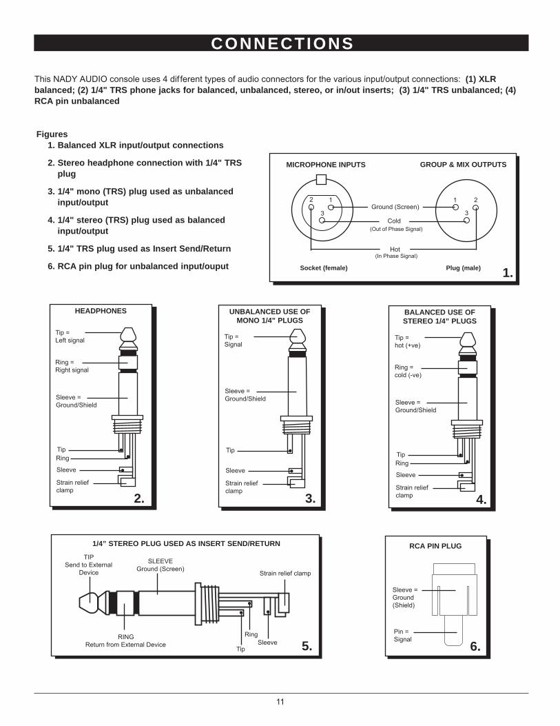
This NADY AUDIO console uses 4 dif ferent types of audio connectors for the various input/output connections: (1) XLRbalanced; (2) 1/4" TRS phone jacks for balanced, unbalanced, stereo, or in/out inserts; (3) 1/4" TRS unbalanced; (4)RCA pin unbalanced
1 2
3
2 1
3
Figures1. Balanced XLR input/output connections
2. Stereo headphone connection with 1/4" TRSplug
3. 1/4" mono (TRS) plug used as unbalancedinput/output
4. 1/4" stereo (TRS) plug used as balancedinput/output
5. 1/4" TRS plug used as Insert Send/Return
6. RCA pin plug for unbalanced input/ouput
Ground (Screen)
Cold(Out of Phase Signal)
Hot(In Phase Signal)
MICROPHONE INPUTS GROUP & MIX OUTPUTS
Socket (female) Plug (male)
HEADPHONES
Tip =Left signal
Ring =Right signal
Sleeve =Ground/Shield
TipRing
Sleeve
Strain reliefclamp
UNBALANCED USE OFMONO 1/4” PLUGS
Tip =Signal
Sleeve =Ground/Shield
Tip
Sleeve
Strain reliefclamp
BALANCED USE OFSTEREO 1/4” PLUGS
Tip =hot (+ve)
Ring =cold (-ve)
Sleeve =Ground/Shield
TipRing
Sleeve
Strain reliefclamp
1/4” STEREO PLUG USED AS INSERT SEND/RETURN
TIPSend to External
Device
RINGReturn from External Device
SLEEVEGround (Screen)
11
RCA PIN PLUG
1.
2. 3. 4.
5. 6.Pin =Signal
Sleeve =Ground(Shield)
Tip
RingSleeve
Strain relief clamp

SPECIFICATIONS
3. FREQUENCY RESPONSEANY INPUT TO ANY OUTPUT ........................................20Hz ~ 20kHz +/-3 dB
4. TOTAL HARMONIC DISTORTIONANY INPUT TO ANY OUTPUT..................................................................0.08%
5. INPUT CHANNEL EQUALIZATIONHigh ........................................12k, +/-15 dB, Q fixed at 2 oct.Low ....................................80 Hz, +/- 15 dB, Q fixed at 2 oct.Low Cut (High Pass)filter (Mono channels only) ............75 Hz, -3 dB (18 dB/octave)
6. GAIN CONTROL RANGEMono input channeltrim control ........................................................................40 dB Channel/Master gain controls.................... +14 dB from 0 dBmAux Send ..................................................+12 dB from +4 dBm
7. CROSSTALK @ 1KHZADJACENT CHANNEL INPUTS ..................................-100 dBINPUT TO OUTPUT.................................................... -40.6 dB
8. HUM AND NOISEResidual Output Noise ..............................................-73.7 dBmS/N Ratio ..................................................................-93.3 dBm
9. VU METERS 6-segment LED X 2 (+7 to -10) L/R
10. PHANTOM POWER+48 VDC, globally selected
11. POWER REQUIREMENTSExternal PSU, 120 VAC/60Hz or 230 VAC/50Hz
12. POWER CONSUMPTION16.2 Watts, External PSU
13. DIMENSIONS AND WEIGHT8.125" x 1.625" x 9" (206 mm x 41 mm x 228.6 mm),4.85 lbs (2.2 Kg)
1. INPUT SECTIONInput Connector Input Impedance Nominal Level Max Level
MONO CH MIC XLR 1.3K Ω -28 dBm -1.0 dBm
MONO CH LINE 1/4" TRS 11K Ω -10 dBm +17 dBm
STEREO CH LINE 1/4" TRS 10K Ω -10 dBm +10 dBm
STEREO TAPE IN RCA PIN JACKS 10K Ω -9 dBm +8 dBm
AUX RETURNS 1/4" TS 5K Ω -11 dBm +8 dBm
2. OUTPUT SECTION
Output Connector Output Impedance Nominal Level Max Level
STEREO OUT L/R 1/4" TS 210 Ω +4.6 dBm +20 dBm
AUX SENDS 1/4" TS 210 Ω -22.2 dBm -6.4 dBm
CNTRL R. OUT 1/4" TS 22 Ω -19.4 dBm +20 dBm
REC OUT RCA PIN JACKS 1K Ω -10.6 dBm +4.8 dBm
PHONES 1/4" TRS 22 Ω +19.4 dBm 22mW X 2
12
The specifications above are correct at the time of printing of this manual. For improvement purposes, all specifications for this unit,including design and appearance, are subject to change without prior notice.
Setting: MONO OUT, +4dBm/400Hz, All Pots at MID, Master at MAX.

BLOCK DIAGRAM
13
L R
LRAUXLPFLRPFL
_+
Ch
ann
els
1 -
2
Ch
ann
els
3/4
- 5/
6
Ch
ann
els
7/8
- 9/
10
AU
X to
Met
erD
ispl
ay(s
witc
h) a
ndC
TR
L R
/P
HO
NE
S
AF
L (
switc
h)S
tere
o or
Mon
o
RL RL
RL
BA
LA
UX
SE
ND
CT
RL
R /
PH
ON
ES
Left
Mon
o
Line
Inpu
t
AU
X R
etur
n Le
ft
Ste
reo
Out
Lef
t
Ste
reo
Out
Rig
ht
Rig
ht
AU
X R
etur
n R
ight
Hea
d P
hone
AU
X S
end
AU
X
GA
IN
Con
trol
Roo
m
Pha
ntom
48V
2 E
Q
Hi
Low
MIC
Inpu
t
3
12
TR
IM
2 E
Q
Hi
Low
2 E
Q
Hi
Low
Inse
rt
LOW
CU
T
Pea
k In
d.
GA
INP
AN
AU
X
PR
E/P
OS
T
PF
L
PR
E/P
OS
T
PF
L
PF
L
TAP
E L
EV
EL
PF
L
AU
X R
ET
UR
N
Rig
ht
Left
Tape
In
Fad
erM
AS
TE
R
Fad
erM
ON
O
Mon
o O
ut
LED
Ind.
Lef
t
LED
Ind.
Rig
ht
Line
Rig
ht
Left
Tape
Out

NOTES
14

ONE YEAR LIMITED WARRANTY
Nady Systems, Inc. warrants to the original consumer purchaser that the unit is free from any defects in material or workman-ship for a period of one year from the date of original retail purchase. If any such defect is discovered within the warranty period, Nady Systems, Inc. will repair or replace the unit free of charge, subject to verification of the defect or malfunction upon return to Nady Systems. Please do not return your Nady product to the store where it was purchased as Nady Systems handles your warranty service directly. Communication with our Service Department is the most efficient means of servicing your unit and we are dedicated to keeping you a satisfied customer.
To the extent permitted by law, any applicable implied warranties, including warranties of merchantability and fitness are hereby limited to one year from the date of purchase. Consequential or incidental damages resulting from a breach of any applicable express or implied warranties are hereby excluded. This warranty is in lieu of all other agreements and warranties, general or special, express or implied and no representative or person including a Nady dealer, agent, or employee is authorized to assume for us any other liability in connection with the sale or use of this Nady Systems’ product.
Whereas some states do not allow limitations on how long implied warranties last, and do not allow exclusion of incidental or consequential damages, the above limitations and exclusions may not apply to you. This warranty gives you specific legal rights and you may also have other rights which may vary from state to state.
This warranty is subject to the following conditions:
1) This system must have been purchased from an authorized Nady dealer and all warranty service must be performed by Nady’s service department. Any service not performed by Nady will automatically void this warranty.
2) Items not covered: physical damage resulting from improper handling of the unit in transit from the factory by the shipper (Nady Systems is not responsible for such damage and all such claims must be made against the shipping company by the consignee); defects caused by normal wear of the product (expendable parts are typically connectors, cables, potentiometers, switches and similar components); damage or defects caused by abuse, neglect, accident, failure to connect or operate the unit in any way that does not comply with applicable technical or safety regulations, or improper repair, excessive heat or humidity, alteration or unreasonable use of the unit, causing cracks, broken cases/housings or parts; damage caused by leaking batteries; finish or appearance items; items damaged in shipment en route to Nady Systems, Inc. for repair. The warranty is null and void if any Nady serial number has been removed or defaced.
How To Obtain Service:
1) If factory service is required, you must contact our Service Department at (510) 652-2411 for a return authorization (RA) number. Make sure the RA number is clearly marked on the outside of your package.(Please note: if an RA number is not included, our shipping department cannot accept your package.)
2) Send the unit back to Nady Systems, 6701 Shellmound Street, Emeryville, CA, 94608, freight pre-paid. You must include proof of date and place of purchase (i.e., photocopy of your bill of sale) or Nady cannot be responsible for repair or replacement. Nady Systems, Inc. will not repair, nor be held responsible, for any units returned without proper identification, return address, and RA number clearly marked on the package.
3) Per the above, Nady will perform all warranty service and return the unit to you at no charge. Nady Systems will inform the buyer if product sent in does not meet the terms of this warranty and will provide a quote for fixing the unit and/or shipping it back exclusively at the buyer’s expense.
15

NADY SYSTEMS, INC. • 6701 SHELLMOUND STREET, EMERYVILLE, CA 94608Tel: 510.652.2411 • Fax: 510.652.5075 • www.nady.com
SERVICE FOR YOUR NADY AUDIO PRODUCT
(U.S.) Should your NADY AUDIO product require service, please contact the Nady Service Department viatelephone at (510) 652-2411, or e-mail at [email protected].
(International) For service, please contact the NADY AUDIO distributor in your country through the dealer fromwhom you purchased this product.
DO NOT ATTEMPT TO SERVICE THIS UNITYOURSELF AS IT CAN BE DANGEROUSAND WILL ALSO VOID THE WARRANTY.