Embed Size (px)
Citation preview
Sri Chandrasekharendra Saraswathi Viswa Maha Vidyalaya
Sri Chandrasekharendra Saraswathi Viswa Mahavidyalaya
SCSVMV University
Department of Electrical and Electronics Engineering
(University Established Under Section III of the UGC Act, 1956)
Accredited with “A” Grade by NAAC
CURRICULUM - BE [Part Time]
For Candidates admitted from the year 2015 Onwards
DURATION OF THE PROGRAMME
A student is normally expected to complete BE Programme in Three and Half years but in any
case not more than Six years from the time of admission.
ASSESSMENT
The break – up of assessment and examination marks for the Theory subjects is as follows:
First Assessment : 15 marks
Final Assessment : 15 marks
Assignments : 10 marks
Examination : 60 marks
The break – up of assessment and examination marks for the Practical subjects is as follows:
First Assessment (Test) : 15 marks
Final Assessment (Test) : 15 marks
Maintenance of record book : 10 marks
Examination : 60 marks
The project work will be assessed for 100 marks by the committee, consisting of the guide and a minimum of two members nominated by Head of the department.
One of the committee members will be nominated as the chairman by Head of the department. The
head of the department may himself be a member or the chairman. 100 marks are allotted for the
project work and viva voice examination at the end of the semester.
ATTENDANCE REQUIREMENTS
A student who withdraws from or does not meet the minimum attendance requirement in course must re-register for and repeat the course.
CHOICE BASED CREDIT SYSTEM FOR BE (EEE) PROGRAMME
To be eligible to appear for the examination in a particular course, a student must put in minimum of
80% in the course. However, if the attendance is 70% or above but less than 80% in any course, the
authorities can permit the student to appear for the examination in the course on payment of the
prescribed condonation fees.
PASSING AND DECLARATION OF EXAMINATION RESULTS
All assessments of all the courses on absolute marks basis will be considered and passing by the results
passing board in accordance with the rules of the university. Thereafter, the controller of examinations
shall convert marks for each course to the corresponding letter grade as follows, Compute the grade
point average and cumulative grade point average, and prepare the grade cards.
90 to 100 marks : Grade ‘S’
80 to 89 marks : Grade ‘A’
70 to 79 marks : Grade ‘B’
60 to 69 marks : Grade ‘C’
55 to 59 marks : Grade ‘D’
50 to 54 marks : Grade ‘E’
Less than 50 marks : Grade ‘F’
Insufficient Attendance : Grade ‘I’
Withdrawn from course : Grade ‘W’
A student who obtains less than 24 marks out of 60 in the examination or is absent for the examination will be awarded grade ‘F’.
A student who earns a grade of S, A, B, C, D, or E for a course is declared to have successfully completed
that course and earned credits for that course. Such a course cannot be repeated by the student.
A student who obtains letter grade F in a course has to reappear for the examinations in that course.
A student who obtains letter grade I or W in a course has to re – register for and repeat the course.
The following grade points are associated with each letter grade for and repeat the point average and cumulative grade point average.
S –10; A – 09; B – 08; C – 07; D – 06; E – 05; F – 0.
Course with grades I and W are not considered for calculation of grade point average or cumulative grade point average. F grade will be considered for computing GPA and CGPA.
A student can apply for re – totaling for one or more of his examination answer papers within a week
from the date of issue of the grade sheet to the students on payment of prescribed fee per paper. The
application must be made to the controller of Examinations with the recommendation of the head of the
department. After results are declared, grade cards will be issued to the students. The grade cards will contain the list
of courses registered during the year / semester, the grades scored and the grade point average (GPA)
for the year / semester.
GPA is the sum of the products of the number of credits of a course with the grade point scored in that
course, taken over all the courses for the year/ semester, divided by the sum of the number of credits for
all courses taken in that year / semester. CGPA is similarly calculated considering all the courses taken
from the time of admission.
After successful completion of the programme, the degree will be awarded with the following classification based on CGPA.
For First Class With Distinction the student must, pass all the courses in the first attempt and obtain a CGPA OF 8.25 or above.
For First Class the student must obtain a CGPA of 6.5 or above.
For Second Class the student must clear all the subjects with in six years from the date of admission.
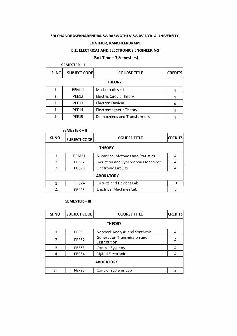
SRI CHANDRASEKHARENDRA SWRASWATHI VISWAVIDYALA UNIVERSITY,
ENATHUR, KANCHEEPURAM.
B.E. ELECTRICAL AND ELECTRONICS ENGINEERING
(Part-Time – 7 Semesters)
THEORY
1. PEM11 Mathematics – I 4
2. PEE12 Electric Circuit Theory 4
3. PEE13 Electron Devices 4
4. PEE14 Electromagnetic Theory 4
5. PEE15 Dc machines and Transformers 4
SEMESTER – II
SI.NO SUBJECT CODE COURSE TITLE CREDITS
THEORY
-
PEP25
SI.NO SUBJECT CODE COURSE TITLE CREDITS
THEORY
Generation Transmission and Distribution
4
LABORATORY
1. PEP35 Control Systems Lab 3
Electrical Machines Lab 3
1. PEE31 Network Analysis and Synthesis 4
2. PEE32
1. PEM21 Numerical Methods and Statistics 4
2. PEE22 Induction and Synchronous Machines 4
3. PEC23 Electronic Circuits 4
SEMESTER – I
SI.NO SUBJECT CODE COURSE TITLE CREDITS
LABORATORY
1.
SEMESTER – III
PEE24 Circuits and Devices Lab 3 2.
3. PEE33 Control Systems 4
4. PEC34 Digital Electronics 4
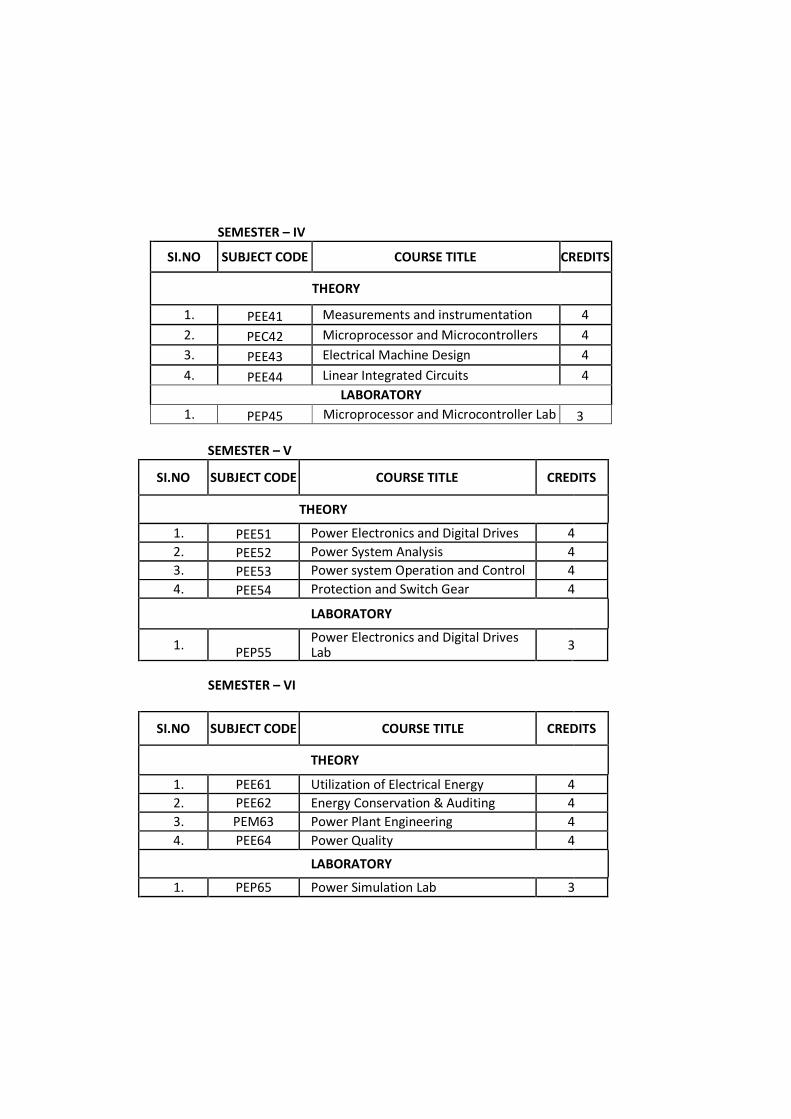
SEMESTER – IV
SI.NO SUBJECT CODE COURSE TITLE CREDITS
THEORY
1. PEE41 Measurements and instrumentation 4
2. PEC42 Microprocessor and Microcontrollers 4
3. PEE43 Electrical Machine Design 4
4. PEE44 Linear Integrated Circuits 4
LABORATORY
1. PEP45 Microprocessor and Microcontroller Lab 3
SEMESTER – V
SI.NO SUBJECT CODE COURSE TITLE CREDITS
THEORY
1. PEE51 Power Electronics and Digital Drives 4
2. PEE52 Power System Analysis 4
3. PEE53 Power system Operation and Control 4
4. PEE54 Protection and Switch Gear 4
LABORATORY
1. PEP55
Power Electronics and Digital Drives Lab
3
SEMESTER – VI
SI.NO SUBJECT CODE COURSE TITLE CREDITS
THEORY
1. PEE61 Utilization of Electrical Energy 4
2. PEE62 Energy Conservation & Auditing 4
3. PEM63 Power Plant Engineering 4
4. PEE64 Power Quality 4
LABORATORY
1. PEP65 Power Simulation Lab 3
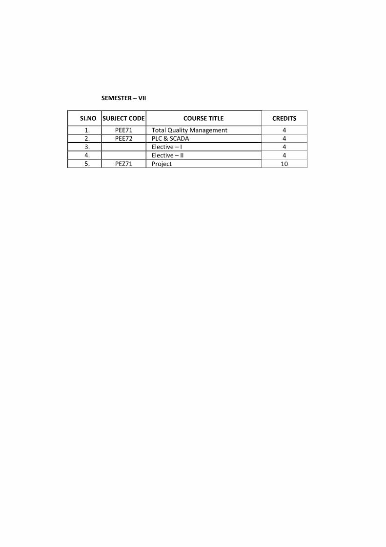
SEMESTER – VII
SI.NO SUBJECT CODE COURSE TITLE CREDITS
1. PEE71 Total Quality Management 4
2. PEE72 PLC & SCADA 4
3. Elective – I 4
4. Elective – II 4
5. PEZ71 Project 10
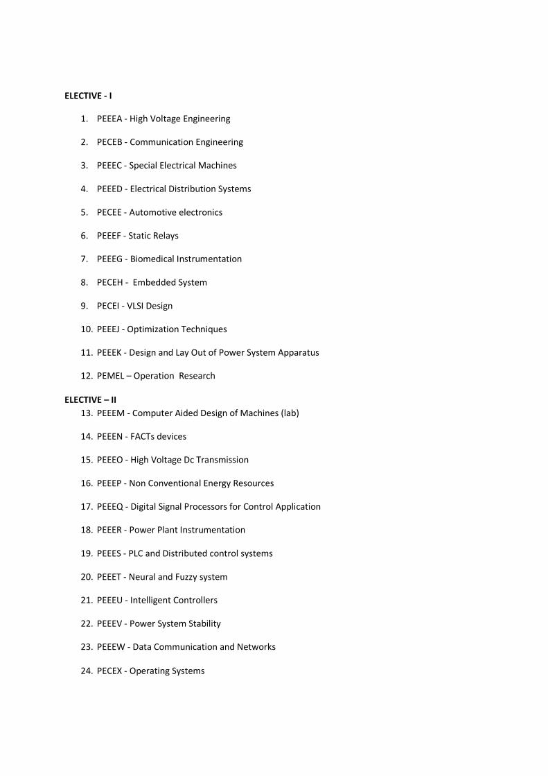
ELECTIVE - I
1. PEEEA - High Voltage Engineering
2. PECEB - Communication Engineering
3. PEEEC - Special Electrical Machines
4. PEEED - Electrical Distribution Systems
5. PECEE - Automotive electronics
6. PEEEF - Static Relays
7. PEEEG - Biomedical Instrumentation
8. PECEH - Embedded System
9. PECEI - VLSI Design
10. PEEEJ - Optimization Techniques
11. PEEEK - Design and Lay Out of Power System Apparatus
12. PEMEL – Operation Research
ELECTIVE – II
13. PEEEM - Computer Aided Design of Machines (lab)
14. PEEEN - FACTs devices
15. PEEEO - High Voltage Dc Transmission
16. PEEEP - Non Conventional Energy Resources
17. PEEEQ - Digital Signal Processors for Control Application
18. PEEER - Power Plant Instrumentation
19. PEEES - PLC and Distributed control systems
20. PEEET - Neural and Fuzzy system
21. PEEEU - Intelligent Controllers
22. PEEEV - Power System Stability
23. PEEEW - Data Communication and Networks
24. PECEX - Operating Systems
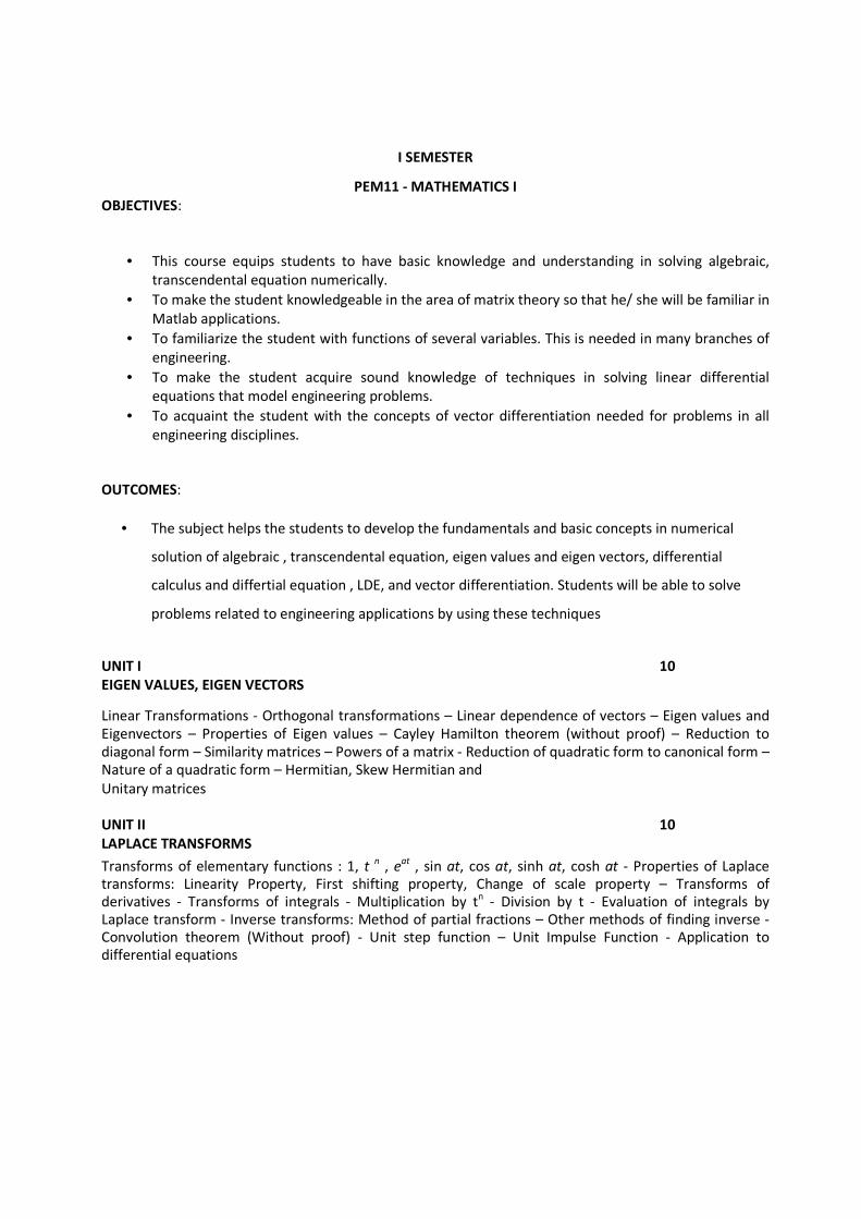
I SEMESTER
• This course equips students to have basic knowledge and understanding in solving algebraic,
transcendental equation numerically.
• To make the student knowledgeable in the area of matrix theory so that he/ she will be familiar in
Matlab applications.
• To familiarize the student with functions of several variables. This is needed in many branches of
engineering.
• To make the student acquire sound knowledge of techniques in solving linear differential
equations that model engineering problems.
• To acquaint the student with the concepts of vector differentiation needed for problems in all
engineering disciplines.
OUTCOMES:
• The subject helps the students to develop the fundamentals and basic concepts in numerical
solution of algebraic , transcendental equation, eigen values and eigen vectors, differential
calculus and differtial equation , LDE, and vector differentiation. Students will be able to solve
problems related to engineering applications by using these techniques
UNIT I 10
EIGEN VALUES, EIGEN VECTORS Linear Transformations - Orthogonal transformations – Linear dependence of vectors – Eigen values and
Eigenvectors – Properties of Eigen values – Cayley Hamilton theorem (without proof) – Reduction to
diagonal form – Similarity matrices – Powers of a matrix - Reduction of quadratic form to canonical form –
Nature of a quadratic form – Hermitian, Skew Hermitian and Unitary matrices
UNIT II 10
LAPLACE TRANSFORMS Transforms of elementary functions : 1, t
n , e
at , sin at, cos at, sinh at, cosh at - Properties of Laplace
transforms: Linearity Property, First shifting property, Change of scale property – Transforms of
derivatives - Transforms of integrals - Multiplication by tn - Division by t - Evaluation of integrals by
Laplace transform - Inverse transforms: Method of partial fractions – Other methods of finding inverse -
Convolution theorem (Without proof) - Unit step function – Unit Impulse Function - Application to
differential equations
PEM11 - MATHEMATICS I
OBJECTIVES:
UNIT III 10
FOURIER SERIES
Euler’s Formulae (Without Proof) – Condition for Fourier expansion – Functions having points of
discontinuity – Change of interval – Expansions of even and odd functions - Half-Range series – Parseval’s
formula (without proof) – Root mean square value (without proof) – Typical waveforms (Definition Only):
Square wave form, Saw toothed waveform, Modified saw toothed waveform, Triangular waveform, Half
wave rectifier, Full wave rectifier
UNIT IV 10
FOURIER TRANSFORMS
Fourier integral theorem (without proof) - Fourier Sine and Cosine integrals – Complex form of Fourier
integral - Fourier integral representation of a function - Fourier transform – Fourier sine and Cosine
transforms – Properties of Fourier Transforms: Linear property, Change of scale property, Shifting
property - Parseval’s identity for Fourier transforms (without proof)
UNIT V 10
VECTOR CALCULUS
Differentiation of vectors - Curves in plane - Velocity and acceleration - Scalar and vector point functions -
Del applied to scalar point functions : Gradient - Del applied to vector point functions : Divergence and
curl - Physical interpretation of divergence and curl – Del applied twice to point functions - Del applied to
products of point functions - Integration of vectors - Line integral - Surface integral - Green's theorem in
the plane (without proof) - Stoke's theorem (without proof) - Volume integral - Gauss divergence theorem
(without proof) - Irrotational fields
L = 40 T = 10 TOTAL = 50
TEXT BOOK:
1. Grewal B.S, Higher Engineering Mathematics, 43rd Edition, Khanna Publishers, New Delhi, 2014.
REFERENCE BOOKS:
1. Alan Jeffrey, Advanced Engineering Mathematics, Academic Press, 6th
Edition,2001
2. Erwin Kreyszig, Advanced Engineering Mathematics, John Wiley & Sons, 9th Edition,2011
3. Gerald C.F and Wheatley P.O, Applied Numerical Analysis, Addison-Wesley Publishing Company,
7th Edition,2014
I SEMESTER
PEE12– ELECTRIC CIRCUIT THEORY OBJECTIVES:
• To introduce electric circuits and its analysis
• To impart knowledge on solving circuits using network theorems
• To introduce the phenomenon of resonance in coupled circuits.
• To educate on obtaining the transient response of circuits.
• To Phasor diagrams and analysis of three phase circuits
OUTCOMES:
• Ability analyses electrical circuits
• Ability to apply circuit theorems
• Ability to analyze AC and DC Circuits
UNIT I 10
BASIC CIRCUIT CONCEPTS Lumped circuits – Kirchhoff‟ s Laws – Voltage -current-relationships of R, L and C – Independent sources –
Dependent sources – simple resistive circuits – Network reduction – Voltage division – Current division –
Source transformation.
UNIT II 10
SINUSOIDAL STEADY STATE ANALYSIS Phasor – Sinusoidal steady state response – Concepts of impedance and Admittance- Analysis of simple
circuits – Power and Power Factor – Series Resonance and Parallel Resonance – Bandwidth and Q factor.
Solution of three-phase balanced circuits – Power measurements by two-wattmeter methods – Solution of
three-phase unbalanced circuits.
UNIT III 10
MESH-CURRENT AND NODE-VOLTAGE METHODS Formation of matrix equations and analysis of complex circuits using mesh-Current and nodal-Voltage methods – Mutual Inductance – Coefficient of coupling – Ideal transformer.
UNIT IV 10
NETWORK THEOREMS AND APPLICATIONS Superposition theorem – Reciprocity theorem – Compensation theorem – Substitution theorem – Maximum power transfer theorems – Thevenin‟ s theorem – Norton‟ s theorem and Millman‟ s theorem with applications.
UNIT V 10
TRANSIENT ANALYSIS
Forced and free response of RL, RC and RLC circuits with D.C. and sinusoidal excitations.
L = 40 T = 10 TOTAL = 50
TEXT BOOK
1. Paranjothi S.R., „Electric Circuit Analysis‟ , New Age International Ltd., Delhi, 2nd Edition, 2000.
REFERENCE BOOKS
1. Hyatt, W.H. Jr and Kemmerly, J.E., „Engineering Circuits Analusis‟ , McGraw- Hill International Editions,
1993.
2. Edminister, J.A., „Theory and Problems of Electric Circuits‟ , Schaum‟ s outline series McGraw Hill Book
Company, 2nd Edition, 1983.
3. Sudhakar, A. and Shyam Mohan S.P.,‟ Circuits and Network Analysis and Synthesis‟ , Tata McGraw-Hill Publishing C.Ltd., New Delhi, 1994.
I SEMESTER
PEE13- ELECTRON DEVICES OBJECTIVES: To acquaint the students with construction, theory and characteristics of the following electronic devices:
i)P-N junction diode
ii)Bipolar transistor
iii)Field Effect Transistor
iv)LED, LCD &other photo electronic devices.
v)Power control/Regulator devices
OUTCOMES: 1. To explain the structure of basic electronic devices.
2. To design applications using basic electronic devices.
UNIT I 10
SEMICONDUCTOR DIODE
Energy bands in solids, Insulators, Semi-conductors and metals - Review of Extrinsic semi-conductors,
Mobility, conductivity, Drift and. Diffusion currents in semi-conductor-Junction transistor – transistor
construction – detailed study of currents in transistor rs - Theory of p-n junction – PN Junction as diode – p-
n diode currents –volt - amp characteristics–diode resistance – temperature effect of p-n junction – diode
switching times - avalanche breakdowns, Tunnel diode clipper, clamper, Zener voltage regulator.
UNIT II 10
BI-POLAR TRANSISTOR
Bi-polar transistor – input and output characteristics of CE, CB and CC configurations – transistor hybrid
model for CE configuration – analytical expressions for transistor characteristics – transistor switching times – voltage rating – power transistors.
UNIT III 10
FIELD EFFECT TRANSITORS Junction field effect transistor – pinch off voltage – JFET volt-ampere characteristics– JFET small signal model – MOSFETS and their characteristics – FET as a variable resistor.
UNIT IV 10
OPTO ELECTRONIC DEVICES
Photo emissivity and photo electric theory – theory, construction and characteristics: light emitting diodes – liquid crystal cell – seven segment display – photo conductive cell – photodiode – solar cell – photo transistor – opto couplers – laser diode.
UNIT V 10
POWER DEVICES
UJT -Construction and characteristics. Switching Mechanism, SCR-VI characteristics - Triggering and
commutation method-applications of SCR, Protection of SCR – characteristics and applications of Triac and
Diac.
L = 40 T = 10 TOTAL = 50
TEXT BOOKS:
1. Jacob.Millman, Christos C.Halkias, „Electronic Devices and Circuits‟ , Tata McGraw-Hill Publishing Limited, New Delhi -Reprint 2003. 2. David A.Bell, „Electronic Devices and Circuits‟ , Prentice Hall of India Private Limited, New Delhi – 2003.
REFERENCE BOOKS:
1. Ben G.Streetman and Sanjay Banerjee, „Solid State Electronic Devices‟ , Pearson Education Asia,
New Delhi – Reprint 2002.
2. Allen Mottershead, „Electronic Devices and Circuits – An Introduction‟ , Prentice Hall of India, Private Limited, New Delhi – 2003.
3. Theodre. F. Boghert, „Electronic Devices & Circuits‟ , Pearson Education, VI Edition, 2003.
.
-
I SEMESTER
PEE14 - ELECTROMAGNETIC THEORY OBJECTIVES:
• To introduce the basic mathematical concepts related to electromagnetic vector fields
• To impart knowledge on the concepts of electrostatics, electrical potential, energy density and
their applications.
• To impart knowledge on the concepts of magnetostatics, magnetic flux density, scalar and vector
• potential and its applications.
• To impart knowledge on the concepts of Faraday’s law, induced emf and Maxwell’s equations • To impart knowledge on the concepts of Concepts of electromagnetic waves and Pointing vector
OUTCOMES:
• Ability to understand and apply basic science, circuit theory, Electro-magnetic field theory control theory and apply them to electrical engineering problems.
UNIT I 10
ELECTROSTATICS The field concept – Sources of Electromagnetic fields.-Changes – Columb‟ s Law – Electric field intensity – Electric flux – Gauss‟ s law – Potential – boundary value problems – Laplace and Poissons equations – Electrostatic energy – Dielectrics – Capacitance.
UNIT II 10
MAGNETOSTATICS Current density – Magnetic field – Magnetic flux – Biot – Savart – Ampere‟ s law – Torque – Force – Vector
potential – Boundary value problem.
UNIT III 10
ELECROMAGNETIC FIELDS Faraday‟ s Law – Lenz‟ s law – Maxwell’s equations – Displacement current – Eddy current – Relation
between field theory and circuit theory.
UNIT IV 10
ELECTROMAGNETIC WAVES Generation – Propagation of waves in dielectrics – Conductors and Transmission lines – Pointing vector – Skin effect.
UNIT V 10
FIELD MODELLING AND COMPUTATION
Problem formulation – boundary conditions – solutions – analytical methods – variables separable methods
– conformal transformation – method of images – numerical methods – finite difference method – finite
element method – charge Simulation Method.
L = 40 T = 10 TOTAL = 50
TEXT BOOKS
1. John D Kraus, „Electromagnetics‟ , McGraw-Hill Book Co., New York, Third Edition, 1989.
2. Joseph A Edminister, „Theory and Problems of Electro magnetics‟ , Schaums outline series
McGraw-Hill book company New York, 1986.
3. William H.Hayt, Jr., „Engineering Electromagnetic,‟ Tata McGraw-Hill Edition, New Delhi, 1998.
REFERENCE BOOKS
1. David J Griffith, „Introduction to Electrodynamics,‟ Prentice Hall of India Pvt. Ltd, New Delhi, Second Edition, 1997. 2. Richard E. Dubroff, S.V.Marshall, G.G.Skitek, „Electromagnetic Concepts and Applications‟ , Fourth Edition, Prentice Hall of India Pvt. Ltd., New Delhi, 1996.
3. Kraus and Fleish, „Electromagnetics with Applications‟ , McGraw-Hill International EditionsFifth
Edition 1999.
I SEMESTER
PEE15 - DC MACHINES AND TRASFORMERS OBJECTIVES:
• To understand the generation of D.C. voltages by using different types of generators and Study
their performance.
• To study the working principles of D.C. motors and their load characteristics, starting and Methods
of speed control.
• To familiarize with the constructional details of different type of transformers, working principle
and their performance.
• To estimate the various losses taking place in D.C.machines and transformers and to study the
different testing method to arrive at their performance
OUTCOMES:
• After the study the students will understand the concepts of electromechanical energy conversions
in D.C. machines and energy transfer in transformers and also to analyze their performance.
UNIT I 10
D.C MACHINE CONSTRUCTION
Field System-Armature Core-Commutator and Brushes-Armature winding- E.M.F equation-Methods of
Excitation-Armature Reaction-Commutation-Load Characteristics of D.C generators- Series, shunt and compound machines.-Parallel operation of D.C Generators.
UNIT II 10
D.C MOTORS
Principle- Back EMF- Torque-Load characteristics of series shunt compound motors-Three point, four point
& Automatic starter for D.C Motors-Speed Control of D.C Motors. Losses-Efficiency of D.C motors &
Generators -Brake test, Swinburnes test, Hopkinsons test, Field test for Series Machines.
UNIT III 10
TRANSFORMERS
Principle-Emf equation and transformation ratio-Types of transformers- Construction-Phasor diagram at different load equivalent circuit-voltage regulation-Losses and efficiency- All day efficiency.
UNIT IV 10
TRANSFORMERS TESTING & PARALLEL OPERATION Polarity and ratio test-O.C and S.C test-load test- parallel operation -Three phase Transformer connections-open delta-Leblanc connection- Three phase to single phase conversion-Tap changing
UNIT V 10
SPECIAL TYPE OF TRANSFORMERS Auto Transformers - Current & Potential transformers- Earthling -Transformer- Welding Transformer-Distribution Transformer -Power Transformer-Construction & Operating principle -Transformer protection.
L = 40 T = 10 TOTAL = 50
TEXT BOOKS
1. B.L.Theraja & A.K.Theraja, “Electrical Technology” , Vol – II, S.Chand Company Ltd, New Delhi, 2007.
2. A.C & D.C Machines-K. Rajput, Laxmi Publishers.
REFERENCE BOOKS
1. D.C Machines and Transformer -Dr.Murgesh Kumar, Vikas Publishers, 1998.
II SEMESTER
PEM21 - NUMERICAL METHODS & STATISTICS OBJECTIVES:
• This course aims at providing the necessary basic concepts of a few numerical methods and give
procedures for solving numerically different kinds of problems occurring in engineering and
technology
OUTCOMES:
• The students will have a clear perception of the power of numerical techniques, ideas and would
be able to demonstrate the applications of these techniques to problems drawn from industry,
management and other engineering fields.
10
UNIT I NUMERICAL SOLUTION OF ALGEBRAIC, TRANSCENDENTAL AND SIMULTANEOUS EQUATIONS
Solution of algebraic and transcendental equations - Bisection method – Method of false position (Regula-
Falsi Method) - Newton-Raphson Iterative method - Solution of linear simultaneous equations - Direct
methods of solution: Gauss elimination method , Gauss – Jordan method – Iterative methods of solution :
Jacobi’s method , Gauss – Seidel method
UNIT II 10 INTERPOLATION AND NUMERICAL INTEGRATION
Interpolation with equal intervals – Newton’s forward interpolation formula – Newton’s backward
interpolation formula - Interpolation with unequal intervals: Lagrange’s interpolation formula, Newton’s
divided difference formula - Numerical integration: Trapezoidal rule - Simpson’s one-third rule - Simpson’s
three-eighth rule
UNIT III 10 NUMERICAL SOLUTION OF ORDINARY DIFFERENTIAL EQUATIONS
Picard’s method – Taylor series method - Euler’s method – Modified Euler’s method – Runge’s method –
Runge-Kutta method – Predictor-corrector methods: Milne’s method, Adams Bashforth method UNIT IV 10 NUMERICAL SOLUTION OF PARTIAL DIFFERENTIAL EQUATIONS
Classification of second order equations – Finite difference approximation to derivatives – Elliptic
equations: Laplace Equation, Poisson’s equation – Solution of Laplace’s equation – Solution of Poisson’s
equation – Parabolic equations: Heat equation – Solution of heat equation – Hyperbolic equations: Wave
equation – Solution of wave equation
UNIT V 10 STATISTICAL AVERAGES
Measures of central tendency – Mathematical expectation and moments – Measures of dispersion –
Coefficient of variation – Skewness – Kurtosis – Pearson’s shape coefficients – Expected values of a two
dimensional random variables – Linear correlation – Correlation coefficient – Rank correlation coefficient –
Regression – Equation of the regression line
L = 40 T = 10 TOTAL = 50
TEXT BOOKS 1. B.S.Grewal, Higher Engineering Mathematics, 43th Edition, Khanna Publishers, New Delhi, 2014. 2. S.P. Gupta, Statistical Methods, 28
th Edition, Sultan Chand and Sons., New Delhi, 1997.
REFERENCE BOOKS
1. Ward Chenny, David Kincaid, Numerical Mathematics and Computing, Fourth Edition, Brookes and Cole Publishing Company, 1999. 2. Gerald C.F and Wheatley P.O, Applied Numerical Analysis, Addison-Wesley Publishing Company
II SEMESTER
PEE22 - INDUCTION AND SYNCHRONOUS MACHINES OBJECTIVES:
• To know the Construction and performance of salient and non – salient type synchronous
generators
• To provide deep understanding of Principle of operation and performance of synchronous motor.
• To impart knowledge on Construction, principle of operation and performance of induction
machines.
• To provide detailed understanding of Starting and speed control of three-phase induction motors
• To impart a knowledge on Construction, principle of operation and performance of single phase
induction motors and special machines.
OUTCOMES:
• By studying the subject the students will understand the concepts of synchronous and
asynchronous machines and also analyze their performance
UNIT I 10
ALTERNATORS Construction – types – circuit model – synchronous reactance – voltage regulation – EMF, MMF, POTIER and ASA methods – armature reaction – synchronizing – parallel operation
UNIT II 10
SYNCHRONOUS MOTORS Principle-Starting-Speed- torque curves-phasor diagrams- V & inverted V curves- phase modifiers -Hunting in synchronous machines and its prevention - applications
UNIT III 10
THREE PHASE INDUCTION MACHINES
Construction – types – principle of operation – equivalent circuit – torque and power output – testing –
circle diagram – cogging and crawling – starting and speed control – double cage rotor – induction
generator.
UNIT IV 10
SINGLE PHASE INDUCTION MACHINE Single phase induction motor – double revolving field theory – equivalent circuit – performance analysis – load characteristics – starting methods
UNIT V 10
FRACTIONAL HORSE POWER MOTORS Shaded – pole induction motor – variable reluctance motor – stepper motor – AC series motor – repulsion motor – linear motor – permanent magnet DC and AC motors.
L = 40 T = 10 TOTAL = 50
TEXT BOOK 1. B.L.Theraja & A.K.Theraja, “Electrical Technology” , Vol – II, S.Chand Company Ltd, New Delhi, 2007.
REFERENCE BOOKS
1. Fitzgerald,A.E.Charles Kingsley Jr.Stephen D.Umans, „Electric Machinery‟ , McGraw-Hill Book
Company,1992
2. Syed A.Nassar, „Electric Machines and Power System‟ , Volume I, McGraw-Hill Inc., New York,
1995.
3. Dr. Murgesh Kumar, Induction and synchronous machines, vikas publications, New Delhi.
II SEMESTER
PEC23 - ELECTRONIC CIRCUITS
OBJECTIVES:
• To familiarize the student with the analysis and design of basic transistor amplifier circuits,
feedback amplifiers, wave shaping and multi vibrator circuits
OUTCOMES:
• Analyze the different types of diodes, operation and its characteristics
• Design and analyze the DC bias circuitry of BJT and FET
• Design circuits using the transistors, diodes and oscillators
UNIT-I 10
POWER SUPPLIES
Single phase half wave and full wave rectifiers- Bridge rectifiers, Ripple factor, Rectification efficiency,
transformer utilization factor and regulation-Performance characteristics of rectifiers with filters-
Controlled rectifiers-Regulated power supply-Series and shunt type voltage regulators-overload and short
circuit protection.
UNIT -II 10
VOLTAGE AMPLIFIERS
Selection of Q point-DC and AC load lines-input and output impedance, voltage gain, current gain and
power gain calculations for BJT and FET amplifiers in different configurations-Effect of bypass, coupling and
stray capacitances on frequency response- Multi stage amplifiers-RC coupling and transformer coupling-
Overall gain and band width –Darlington
UNIT-III 10
POWER AND DIFFERENTIAL AMPLIFIERS
Class A direct coupled and transformer coupled power amplifiers-Expression for maximum power-
Conversion efficiency with class A and class B operation-Push pull connections-Complimentary symmetry
configuration- distortion Differential amplifier-common and differential mode analysis.
UNIT -IV 10
FEEDBACK AMPLIFIER AND OSCILLATORS Feedback concept- Positive and negative. Series and shunt, voltage and current feedback-Influence of
feedback on input and output impedance, gains stability. Bandwidth and distortion of amplifier-
Barkhausen's criterion for sustained oscillation-RC phase shift and Wein bridge oscillators-Hartley and
Colpitis oscillators-crystal oscillators.
UNIT –V 10
TUNED AMPLIFIERS AND MULIVIBRATORS
Characteristics of tuned amplifiers-Single tuned, double tuned and stagger tuned amplifiers-Bandwidth for
single stage and multi stage amplifiers, Influence of Q of tank circuit-Astable, monostable and Bistable
multivibrators-Schmitt trigger. L = 40 T = 10 TOTAL = 50
TEXT BOOK:
1. G.K.Mithal, Electronics Devices and Circuits, Khanna Publishers.
REFERENCE BOOKS:
1. Y.N.Bapat, Electronic circuit and systems, TATA McGraw Hill. 2. Milman and Taub I Pulse, digital and switching wave forms, McGraw Hill International Editions,
1987.
II SEMESTER
• To provide practical experience with simulation of electrical circuits
and verifying circuit theorems.
OUTCOMES:
• Ability to understand and apply circuit theorems and concepts in
engineering applications.
LIST OF EXPRIMENTS
1. Verification of Kirchhoff‟ s Law.
2. Verification of Norton’s and super position theorem
3. Verification of Maximum Power transfer Theorem.
4. Three phase power and power factor Measurement by 2
wattmeter method
5. Plotting of B- H curve of a magnetic material.
6. Series and Parallel resonance in RLC Circuits.
7. Semiconductor diode and Zener diode characteristics.
8. Input and output characteristics of a BJT in CE configuration
9. Characteristics of JFET and UJT.
10. Characteristics of a SCR & Triac
11. Series and shunt voltage regulator.
12. R.C phase shift and wien bridge oscillator
13. Frequency response of BJT AND FET amplifier
14. Power amplifier
PEE24-CIRCUITS & DEVICES LAB
OBJECTIVES:
II SEMESTER
PEP25- ELECTRICAL MACHINES LABORATORY
OBJECTIVES :
• To expose the students to the operation of D.C. machines and transformers and give them experimental skill.
OUTCOMES:
• After the laboratory, the students understand the basic operation of electrical dc machines and
transformer and help them to develop experimental skills.
LIST OF EXPRIMENTS
1. Open circuit and load characteristics of separately excited and self excited D.C.generator. 2. Load test on D.C. shunt motor. 3. Load test on D.C. series motor. 4. Swinburne’s test and speed control of D.C. shunt motor. 5. Load test on single-phase transformer and open circuit and short circuit test on single-phase
transformer. 6. Regulation of three-phase alternator by EMF and MMF methods. 7. Load test on three-phase induction motor. 8. No load and blocked rotor tests on three-phase induction motor (Determination of equivalent
circuit parameters) 9. Load test on single-phase induction motor. 10. Load test on synchronous motor.
III SEMESTER
PEE31 - NETWORK ANALYSIS AND SYNTHESIS OBJECTIVES
• To analyse the relationship between various two port parameters, ladder and lattice networks.
• To analyse the time response and frequency response
• To synthesise RL, RC & RLC networks by Foster and Cauer form
• To analyse the network solution through graph theory concepts
OUTCOMES
Students can have the ability to
• Analyse various electrical networks by graph theory concepts
• Analyse time and frequency response
• Analyse the stability by Hurwitz polynomials
UNIT I 10
S – DOMAIN ANALYSIS
S - domain network – driving point and transfer impedances and their properties – transform network analysis – poles and zeros of network functions – time response from pole – zero plots.
UNIT II 10
FREQUENCY DOMAIN ANALYSIS
Admittance – loci of RLC networks – frequency response of RLC networks – frequency response from pole
– zero – bode plots.
UNIT III 10
NETWORK TOPOLOGY Network graphs, tree and cut – sets – tie set and cut – set schedules – V shift and I shift – primitive impedance and admittance matrices – application to network solutions.
UNIT IV 10
TWO PORT NETWORKS
Characterization of two port networks in terms of Z , Y,H and T parameters – networks equivalents –
relations between network parameters – Analysis of T, Ladder ,Bridged – T and lattice networks – transfer
function of terminated two port networks .
UNIT V 10
ELEMENTS OF NETWORK SYNTHESIS Reliability of one port network – Hurwitz polynomials and properties – P. R. functions and properties – synthesis of RL, RC and LC one port networks.
L = 40 T = 10 TOTAL = 50
TEXT BOOK
1. Kuo F.F., „Network Analysis and Synthesis‟ , Wiley International Edition, Second Edition, 1966.
REFERENCE BOOKS
1. Paranjothi, S.R., „Electric Circuit Analysis‟ , New age International Publishers, Second Edition, 2000. 2. Van Valkenburg, M.E., „Network Analysis‟ , Prentice – Hall of India Private Ltd., New Delhi, Third Edition, 1974. 3. Sudhakar. A., and Shyammohan , „Circuits and Networks Analysis and Synthesis‟ Tata McGraw Hill Publishing Co. Ltd., New Delhi, 1994.
III SEMESTER
PEE32 - GENERATION, TRANSMISSION AND DISTRIBUTION
OBJECTIVES:
• To develop expressions for the computation of transmission line parameters.
• To obtain the equivalent circuits for the transmission lines based on distance and operating
• Voltage for determining voltage regulation and efficiency. Also to improve the voltage profile of
the transmission system.
• To analyses the voltage distribution in insulator strings and cables and methods to improve the
same.
• To understand the operation of the different distribution schemes.
OUTCOMES:
• Ability to understand and analyze power system operation, stability, control and protection.
UNIT I 10
GENERATION AND DISTRIBUTION SYSTEMS
Hydel, thermal, nuclear, tidal, Biogas,Biomass plants - structure of electric power system – One line
diagram- Generation, Transmission and Distribution systems – Comparison of distribution systems – Radial
and ring systems – Two wire DC,AC single phase and three phase systems – Current and voltage calculation
distribution with concentrated and distributed loads – Kelvin‟ s for the design of feeders and its limitations.
UNIT II 10
LINE PARAMETERS AND CORONA
Resistance and capacitance of single phase and three phase line – Stranded bundled conductor
configuration – Symmetrical and unsymmetrical spacing- Transposition of line conductor – Double circuit
lines-Application of self and GMD – Skin and proximity effects – Earth effect on capacitance –Interference –
Corona characteristics – Effect on performance of lines.
UNIT III 10
PERFORMANCE OF OVER HEAD LINES
Equivalent circuits for short, medium (PI and T circuits) and long lines_ Efficiency and Regular –Tuned
power lines – Attenuation and surge impedance loading – Power circle diagrams for receiving and sending
ends- Transmission capacity – Steady state power limit – Voltage control of lines- Shunt and series
compensation.
UNIT IV 10
UNDERGROUND CABLES AND INSULATORS
Underground cables – Types Construction – Capacitance of cables – Insulation resistance – Dielectric
stresses and grading – Capacitance and intersheath grading – Dielectric loss – Thermal characteristics –
Capacitance of three core cables – Fault location – Short circuit and open circuit in – Insulators –Types and
comparison – Voltage distribution in string insulators – String efficiency –Methods of improving efficiency.
UNIT V 10
(MECHANICAL DESIGN AND HVDC TRANSMISSION) Stress and sag calculations – Effect of wind and ice- Supports at different levels – Stringing chart condition
erection – Dampers - HVDC transmission: Comparison of AC and DC systems – Economics distance for DC – Terminal equipment for DC systems.
L = 40 T = 10 TOTAL = 50
TEXT BOOK: 1. C.L. Wadhwa, Electrical power systems, Willey Eastern Limited, NewDelhi, 1985.
REFERENCE BOOKS:
1. W.L. Stevenson, Elements of power systems analysis McGraw hill. 2. S.L.Uppal, Electrical power, khanna publishers, NewDelhi, 1981. 3. Soni, Bhatnagar and Gupta, A course in electrical power Dhanpat Raj & Sons, NewDelhi, 1976.
OBJECTIVES:
The course should enable the students to:
• Analyze representation of systems and to derive transfer function models.
• Provide adequate knowledge in the time response of systems and steady state error analysis.
• Give basic knowledge in obtaining the open loop and closed-loop frequency responses of systems.
• Provide the concept of stability of control system and methods of stability analysis.
• Study the three ways of designing compensation for a control system.
OUTCOMES:
The students should be able to:
• Describe various input/output models of dynamic system.
• Be familiar with frequency domain descriptions and dynamic analysis.
• Understand the concept of stability and effect of feedback control on sensitivity.
• Apply the basic methods of classical control system design such as root locus and phase lead-lag
compensation based on Bode plots.
• Understand the principles of control theory.
UNIT - I 10
SYSTEM AND THEIR REPRESENTATION
Basic elements of control systems- open and close loop systems – Differential equation - Transfer function
– Modeling of Electrical systems, translational and rotational mechanical systems – Block diagram
reduction techniques – Signal flow graphs.
UNIT - II 10
TIME RESPONSE
Time response – Time domain specifications – types of input – I and II order system response – Error
coefficients – Generalized error series – Steady state error –Effect of P,PI,PD and PID modes of feedback
control ,Analysis using MATLAB.
III SEMESTER
PEE33 - CONTROL SYSTEMS
UNIT - III 10
FREQUENCY RESPONSE
Frequency response – Bode plot – Polar plot – Nyquist plot – Frequency domain specifications from plots –
Constant M and N circles – Nichol’s chart– Analysis using MATLAB.
UNIT -IV 10
STABILITY AND COMPENSATOR DESIGN
Characteristic equation – BIBO stability - Routh Hurwitz criterion - Root locus technique Construction of
Root locus - Nyquist stability criterion – Effect of Lag, Lead and lag-lead compensation on frequency
response, Analysis using MATLAB.
UNIT - V 10
STATE VARIABLE ANALYSIS
Concept of state variables – State models for linear and time invariant systems – solution of state and
output equation in controllable canonical form – concept of controllability and observability – Effect of
state feedback.
L = 40 T = 10 TOTAL = 50
TEXT BOOKS:
1. M.Gopal,”Control system – Principle and Design,” Tata McGraw Hill, second edition, 2002.
2. K.Ogata,”Modern control Engineering, “fifth edition, PHI, 2012.
REFERENCE BOOKS:
1. Benjamin C.Kuo, “Automatic control systems,” seventh edition ,PHI,2010z
.J.Nagrath & Gopal ,”Control System Engineering,” fifth edition,New Age International .
OBJECTIVES:
The course should enable the students to:
• Study various number systems and to simplify the mathematical expressions using Boolean
functions - simple problems.
• Study implementation of combinational circuits.
• Study the design of various synchronous and asynchronous circuits.
• Learn about the various hazards present in the circuit
• Expose the students to various memory devices
OUTCOMES:
The students should be able to:
• Understand the basic number system and Boolean algebra.
• Understand the basics of combinational circuits.
• Know about Flip flops and synchronous sequential circuits and their design.
• Analyse about various hazards present in the circuit.
UNIT - I 10
NUMBER SYSTEMS AND CODES
Review of Number systems: Binary, Octal and Hexadecimal. Representations of numbers and their
conversions. Binary arithmetic's. Conversion algorithms. Weighted binary codes and Non-weighted binary
codes. Error detecting and error correcting codes. Alphanumeric codes.
UNIT - II 10
BOOLEAN ALGEBRA AND LOGIC FUNCTIONS
Boolean Algebra: Introduction to Boolean algebra - The AND, OR and NOT operations. Laws of Boolean
algebra. Minimization of Boolean expression. Boolean expressions and logic diagrams. Universal building
blocks. Negative logic.
Logic Simplifications: Truth tables and maps. Sum-of-products and product-of-sums. Simplification of logic
functions using Karanaugh map Minimization and Quine-McCluskey method of minimization.
PEC34-DIGITAL ELECTRONICS
III SEMESTER
UNIT - III 10
COMBINATIONAL CIRCUITS
Arithmetic circuits: Half Adder, Full Adder, Half Subtractor and Full Subtractor, Number complements.
Multiplexer - Demultiplexer, Decoder and Encoder code converters – BCD to Excess3, Gray, Seven Segment
Display Conversions – Parity Generator and Checkers.
UNIT - IV 10
SEQUENTIAL CIRCUITS
Synchronous sequential circuits: Basic latch circuits - Flip-flops, truth table and excitation table. Shift
Registers. Synchronous counter design using JK, T, D flip flops, Up-down counter, General BCD counter and
Ring counters.
Asynchronous Sequential Circuits – State Reduction, Multiple Inputs.
UNIT - V 10
LOGIC FAMILIES AND PROGRAMMABLE LOGIC DEVICES
Logic Families: BJT as a switch- Logic Specifications – RTL, DTL, IIL, TTL open Collector O/P, Totem pole O/P,
Tristate O/P, Schottky TTL gate, ECL, MOS, CMOS Logic – Comparison of Logic Families.
Programmable Logic Devices: PAL, PLA, PROM.
L = 40 T = 10 TOTAL = 50
TEXT BOOKS:
1. W.H. Gothmann: Digital Electronics - An Introduction, Theory and Practice, PrenticeHall of
India.Second
edition,1992.
2. M.Morris Mano – Digital Logic & Computer Design – PHI, 2nd Edition, 1999.
REFERENCE BOOKS:
1. A. Anand Kumar: Switching Theory and Logic Design – PHI, 2008.
2. Heiser Man: Handbook of Digital IC applications, Prentice Hall.1980.
3. D.J. Comer: Digital Logic and State Machine Design, HOLT-SAUN-DERS, 3rd Edition, 1995.
4. T.L. Floyd: Digital Fundamentals, Prentice Hall of India.3rd Edition,1995.
III SEMESTER
PEP35 - CONTROL SYSTEMS LAB
OBJECTIVES:
• To determine the transfer function of DC Machines and
compensating networks.
• To obtain the transfer function of various servomotors
• To understand the use of various compensators and controllers
• To simulate the various controllers using MATLAB software
• To analyze the stability of control systems using MATLAB
programming.
OUTCOMES :
Ability to understand and apply basic science, circuit theory, Electro-
magnetic field theory , control theory and apply them to electrical
engineering problems.
LIST OF EXPRIMENTS:
1. Transfer function of separately Excited DC generator.
2. Transfer function of field controlled of DC Motor.
3. Transfer function of Armature controlled of DC Motor.
4. DC Position control of Servo System.
5. AC Servo Motor Speed – torque characteristics.
6. AC Position control of Servo System.
7. Experiments using PID Controller.
8. Studies of phase Lead, phase lag, lag lead compensators.
9. Magnetic amplifier characteristics.
10 Experiments using MAT LAB.
IV SEMESTER
OBJECTIVES:
The course should enable the students to:
• Acquire the knowledge on basic measurement concepts
• Acquire the knowledge on basic electronic measurements
• Acquire the knowledge on recording devices
• Acquire the knowledge on digital instruments
OUTCOMES:
At the end of the course the student should be able to:
• Understand Measurement systems, Bridge measurements
• Know the principles of cathode ray oscilloscopes and other measuring instruments
• Compare analog and digital techniques, and measurement errors
PEE41-MEASUREMENTS AND INSTRUMENTATION
UNIT-I 10
SCIENCE OF MEASUREMENT AND CHARACTERISTICS OF TRANSDUCERS
Functional elements of an instrument - Units and standards - calibration methods – errors in measurement -
statistical methods - Static characteristics - accuracy, precision, sensitivity, linearity, Reproducibility,
Repeatability and Noise - Dynamic characteristics – impulse, step, ramp and sinusoidal inputs.
Classification of transducers – Selection of Transducer – Applications of Transducer - Resistive Transducer:
Strain gauges, Resistance Thermometers, Thermistor - Inductive Transducers: LVDT, RVDT- Capacitive
Transducers – Piezoelectric Transducer.
UNIT-II 10
POTENTIOMETERS AND ELECTRICAL INSTRUMENTS
DC potentiometer - Loading effect – Application – Basic circuit - standardization – Laboratory type (Crompton’s)
– AC potentiometer – Drysdale (polar type) type – Gall-Tinsley (coordinate) type – Limitations & applications –
Instrument Transformer - C.T and V.T construction, theory, operation, phasor diagram, characteristics, testing,
error elimination – Applications – Single and three Phase Wattmeters and Energy meter.
UNIT-III 10
MEASUREMENT OF RESISTANCE AND IMPEDANCE
Low Resistance: Kelvin’s double bridge – Ductor Ohmmeter - Medium Resistance: Voltmeter Ammeter method,
Substitution method, Wheatstone bridge method – High Resistance: Megger, Direct deflection method,
Megohm bridge method - Earth resistance measurement. Introduction to A.C. bridges – Sources and Detectors
in A.C. bridges – Measurement of Inductance – Anderson Bridge. - Measurement of Capacitance: Schering’s
bridge, De-Sauty’s bridge - Measurement of frequency using Wien’s bridge- LCR meter- Q meter
1. D. Patranabis, ‘Sensors and Transducers’, Prentice Hall of India, 1999
2. Helfrick & Cooper, Modern Electronic Instrumentation and Measurement Techniques, Prentice Hall of
India,5th Edition,2002.
3. Joseph J Carr, Elements of Electronic Instrumentation & Measurement, Pearson, 3rd Edition 1995.
4. H.S.Kalsi, “Electronic Instrumentation”, TMH Co., 1995.
5. Moorthy, D.V.S., “Transducers and Instrumentation”, Prentice Hall of India Pvt. Ltd., 1995.
6. A.K Sawhney, ‘A course in Electrical & Electronic Measurement and Instrumentation’, Dhanpat Rai and Co
REFERENCE BOOKS:
1. E.A. Doeblin, ‘Measurement Systems – Applications and Design’, Tata McGraw Hill, New York, 1990
2. A.K. Sawhney, ‘A course in Electrical & Electronic Measurement and Instrumentation’, Dhanpat Rai and
Co (P) Ltd., 2004..
3. S. Ranganathan, ‘Transducer Engineering’, Allied Publishers Pvt. Ltd., 2003.
4. Stout M.B., “Basic Electrical Measurement”, Prentice Hall of India, 1986.
5. Dalley,J.W., Riley, W.F. and Meconnel, K.G., “ Instrumentation for Engineering Measurement”, John Wiley
& Sons, 1993.
UNIT- IV 10
CRO AND RECORDING INSTRUMENTS
Oscilloscope: CRO – CRT, Deflection System, Specifications, Controls, Phosphors -Dual Beam / Dual trace
oscilloscope - Storage Oscilloscope, Digital Storage Oscilloscope and Sampling Oscilloscope.
Recording Instruments: Method of Recording – Frequency Modulated (FM) recording-Pulse Duration
Modulation (PDM) Recording - Strip Chart Recorders, X-Y, UV Recorders, and Plotters.
UNIT-V 10
ANALOG & DIGITAL INSTRUMENTS
Operating Forces – Deflecting Force, Controlling Force, Damping Force - Galvanometer, PMMC & moving iron
instruments – Principle of operation, construction and sources of errors and compensation – Dynamo meter –
True RMS meter - electronic voltmeter – Digital Voltmeter – Multimeter – vector voltmeter.
L = 40 T = 10 TOTAL = 50
TEXT BOOKS:
(P) Ltd., 2004.
7. Oliver and Cage, “Electronics measurements & Instrumentation,” TMH Co.
8. M.M.S.Anand,”Electronic instruments and instrumentation thcnology,”PHI, 2006.
OBJECTIVES:
The objective of the course is to impart knowledge on:
1. The Architecture of 8086 & 8051.
2. The addressing modes & instruction set of 8086 & 8051.
3. The need & use of Interrupt structure.
4. Simple program Skills.
5. Commonly used peripheral / interfacing ICs.
OUTCOMES:
After completion of the course the students are expected to be able to:
1. Understand the functional block diagram, Timing Diagram, Interrupt structure and Multiprocessor
configurations of 8086Microprocessor.
2. Develop the Programming skills using Loop structure with counting & Indexing, Look up table,
Subroutine instructions stack.
3. Interface ICs 8255 PPI, 8259 PIC, 8257 DMA, 8251 USART, 8279 Key board display controller and 8253
Timer/ Counter, A/D and D/A converter.
4. Comprehend the Functional block diagram ,Instruction format and addressing modes, Interrupt
structure ,I/O Ports and Serial communication of 8051 Microcontroller.
5. Develop the programming skills in PID control algorithm, square, triangular and sine wave form
generation, closed loop control of servo motor and stepper motor control.
UNIT I 10
INTRODUCTION TO MICROPROCESSOR- 8085
Comparison of microcomputer with "mini" and "large" Computers-Advantages and limitations of
Microprocessor based system design -8085 Microprocessor architecture-Addressing modes- Instruction set-
Programming the 8085- interrupts - Memory and I/O
UNIT II 10
16 – BIT MICROPROCESSOR – 8086
Intel 8086 microprocessor - Architecture - Instruction Set-Addressing Modes-- Assembly Language
Programming-Procedures- Interrupts
PEC42-MICROPROCESSOR AND MICROCONTROLLER
IV SEMESTER
UNIT-III 10
MULTIPROCESSOR CONFIGURATIONS
Coprocessor Configuration – Closely Coupled Configuration – Loosely Coupled Configuration –8087 Numeric
Data Processor – Data Types – Architecture –8089 I/O Processor –Architecture –Communication between CPU
and IOP
UNIT- IV 10
INTERFACING AND SYSTEM DESIGN USING MICRO PROCESSOR
1. 8255-Programmable peripheral Interface along with 8085-Both Mode 0 and Mode 1, detailed study.
2. 8254 - Programmable Interval Timer along with Intel 8086 - Both Mode 0 and Mode 3 to be studied.
3. Need for the following ICs: (a) 8251 - USART; (b) 8257 - Direct Memory Access Controller; (c) 8259-
Programmable Interrupt Controller; (d) 8279 - Keyboard / Display Interface
4. Case studies – Traffic light control, washing machine control- Motor Control- Relay, PWM, DC & Stepper
Motor
UNIT - V 10
MICROCONTROLLERS
Architecture of 8051 Microcontroller – signals – I/O ports – memory – counters and timers – serial data I/O –
interrupts- Interfacing -keyboard, LCD,ADC & DAC
L = 40 T = 10 TOTAL = 50
TEXT BOOKS:
1. Ramesh S. Gaonkar ,”Microprocessor – Architecture, Programming and Applications with the 8085” Penram
International Publisher , 5th Ed.,2006
2. Yn-cheng Liu,Glenn A.Gibson, “Microcomputer systems: The 8086 / 8088 Family architecture, Programming
and Design”, second edition, Prentice Hall of India , 2006 .
3. LA Levant Hal, Introduction to Microprocessor, Software, Hardware, Programming, PHI, Inc.1978.
4..Kenneth J.Ayala, ’The 8051 microcontroller Architecture, Programming and applications‘ second edition
,Penram international.
REFERENCE BOOKS :
1. Douglas V.Hall, “ Microprocessors and Interfacing : Programming and Hardware”, second edition , Tata Mc
Graw Hill ,2006.
2. A.K.Ray & K.M Bhurchandi, “Advanced Microprocessor and Peripherals – Architecture, Programming and
Interfacing”, Tata Mc Graw Hill , 2006.
3. Mohamed Ali Mazidi,Janice Gillispie Mazidi,” The 8051 microcontroller and embedded systems using
Assembly and C”,second edition, Pearson education /Prentice hall of India , 2007.
IV SEMESTER
PEE43 - ELECTRICAL MACHINE DESIGN
OBJECTIVES:
• To study mmf calculation and thermal rating of various types of electrical machines.
• To design armature and field systems for D.C. machines.
• To design core, yoke, windings and cooling systems of transformers.
• To design stator and rotor of synchronous machines and study their thermal behavior.
• To design computer aided design transformer and machines using magnet software
OUTCOMES:
• Ability to model and analyze electrical apparatus and their application to power system
UNIT I 10
MAGNETIC CIRCUIT CALCULATIONS Magnetization characteristics – loss curves – estimation of total mmf – mmf, for airgap – mmf for teeth – significance of Carter‟ s coefficient – real and apparent flux densities – leakage flux – leakage reactance in transformer – leakage reactance in rotating machines – Heating and cooling characteristics.
UNIT II 10
DESIGN OF DC MACHINES
Standard specifications – output equation – output coefficient – choice of specific magnetic and electric
loadings – choice of number of poles – length of airgap – design of armature slot – dimensions of pole –
design of field windings – design of Commutator and brushes – design of interpole and its winding.
UNIT III 10
DESIGN OF TRANSFORMERS
Design of transformers – standard specification – EMF per turn – output equation – window space factor –
specific loadings – dimensions of core and yoke – design of winding – cooling tubes – estimation of no load
current of transformer – change of parameters with change of frequency.
UNIT IV 10
DESIGN OF SYNCHRONOUS MACHINES
Standard specifications – output equation – choice of specific loadings – design of salient pole machines –
short circuit ratio – length of air gap – armature design – design of rotor – design of damper winding –
design of turbo alternator design of three phase induction motor – output equation – choice of specific
loadings – main dimensions – design of stator windings and core – length of air gap – design of cage rotor –
design of wound rotor.
UNIT V 10
COMPUTER AIDED DESIGN
Introduction of computer aided design – advantages – methods of approach- Analysis method – synthesis
method – optimization – general procedure – variables and constraints – optimal design of power
transformer – optimal design of induction motor – optimal design of synchronous machine.(Only for
Demo) Design of DC Machines, Single phase & Three phase Transformer, Single phase & Three phase
induction motor, Synchronous Machines using Magnet Software. L = 40 T = 10 TOTAL = 50
TEXT BOOKS:
1. A course in Electrical Machine Design A.K.Sawhney, Dhanpat rai & co, 1999.
2. Principles of Electrical Machine Design, R.K.Agarwal, S.K.Kataria & sons, 1997.
3. Computer Aided Design of Electrical Equipment, M.Ramamoorthy, Associated East-West Press, 1987.
REFERENCE:
1. The Performance and Design of DC Machines, Clayton & Hancock, oxford and IBH Publishing co, 1988.
2. The Performance and Design of AC Machines, M.G.Say, ELBS, 1974. 3. Electrical Machine Design Data Book –A.Shanmugasundram, G.Gangadhar & R.palani, wiley Estern Ltd., NewDelhi, 1979.
IV SEMESTER
PEE44 - LINEAR INTEGRATED CIRCUITS
OBJECTIVES:
1. To study the IC fabrication procedure
2. To study characteristics; realize circuits; design for signal analysis using Op-amp ICs
3. To study the application of Op-amp
4. To study internal block and the applications of special ICs like timing circuits, regulator circuits,
ADC’s
OUTCOMES:
1. Upon completion of the course, the student will be able to
2. Design linear and non-linear applications of Op-amp
3. Design ADC and DAC using Op-amp
4. Generate waveforms using Op-amp circuits
5. Analyze special function ICs
UNIT I 10
FABRICATION OF INTEGRATED CIRCUITS IC classification, fundamental of monolithic IC technology, epitaxial growth, masking and etching, diffusion
of impurities. Realisation of monolithic ICs and packaging. Fabrication of diodes, capacitance, resistance
and FETs.
UNIT II 10
OP-AMP FUNDAMENTALS, CHARACTERISTICS AND APPLICATIONS Basic information, Op-anp configurations, Ideal op-amp circuit analysis-DC and AC characteristics of ideal
opamp, - Inverting and Non-inverting amplifiers - summing amplifier - difference amplifier - voltage
follower - Differentiator - Integrator - clamper - clipper - sample and hold circuit, Log amplifier and Antilog
amplifier, Multiplier and Divider.
UNIT III 10
COMPARATORS AND WAVEFORM GENERATORS Introduction - Basic comparator application, sine wave generator- wein bridge oscillator and phase shift oscillator, square wave generator, triangular wave generator, saw tooth wave generators, Schmitt trigger-
UNIT IV 10
FILTERS AND CONVERTERS
RC active filters- Low pass , High pass, band pass, band reject and notch filter Digital to analog converters-
basic concepts, analog switches, types-weighted, R-2R ladder DAC. Analog to Digital converter- basic
concepts , types- Flash, successive approximation and dual slope.
UNIT V 10
VOLTAGE REGULATORS AND TIMERS voltage regulators - Fixed voltage regulators, Adjustable voltage regulators -723 general purpose voltage
regulator. IC555 Timer-Timer functional diagram, monostable and astable operation, Schmitt trigger and
their applications.
L = 40 T = 10 TOTAL = 50
TEXT BOOKS
1. Salivahanan S., „Linear Integrated Circuits‟ Tata Mgraw Hill (2008)
2. Roy Choudhury and Shail Jain, 'Linear Integrated Circuits', 1995.
REFERENCE BOOKS
1. Sergio Franco, „Design with Operational Amplifiers and Analog and Integrated Circuits‟ , 2nd Edition, McGraw-Hill, 1997. National Semiconductor/Texas - TTL/MOS/VLSI Data Manuals.
2. Millman, J. and Halkias, C.C., Integrated Electronics-Analog and Digital Systems, McGraw Hill, 9th Reprint, 1995
3. Coughlin R.F. and F.F.Driscall, Operational Amplifiers and Linear Integrated Circuits, Prentice Hall Inc.NJ 1977
IV SEMESTER
PEP45-MICROPROCESSOR AND MICROCONTROLLER LAB
OBJECTIVES
• To provide training on programming of Microprocessor and Microcontroller and
understand the interface requirements
OUTCOMES
• Ability to understand and analyse, linear and digital electronic circuits
• To understand and apply computing platform and software for engineering problems
LIST OF EXPRIMENTS
1. Arranging a string of data ascending and descending order.
2. Multiplication and Division of eight bit binary numbers.
1. Square root of a binary number and use of lookup tables for liberalization.
2. Code conversion: BCD to binary, Binary to BCD, BCD to seven segment LED code, Binary to ASCII and ASCII to binary code.
3. Microprocessor controlled stepper motor speed control.
4. Wave form Generation.
5. Interfacing of 8279 LED Display.
6. Addition and subtraction using 8051 Micro controller.
7. Multiplication using 8051 Micro controller.
8. Interface 8255 in mode 0, mode 1 & mode 2
9. Temperature Sensor Interface
10. Analog to Digital Conversion
11. Digital to Analog Conversion
12. Programs for Sorting and Searching of an element
V SEMESTER
PEE51 - POWER ELECTRONICS AND DIGITAL DRIVES
OBJECTIVES:
• To get an overview of different types of power semi conductor devices and their switching
characteristics.
• To understand the operation, characteristics and performance parameters of controlled rectifier.
• To study the operation, switching techniques and basic topologies of DC-DC switching regulators, AC
voltage controller and matrix and simple application
• To learn different modulation techniques of PWM inverters & to understand the harmonic reduction
methods.
OUTCOMES:
• Ability to understand & analyze linear and non-linear electronic circuits.
UNIT I 10
RECTIFIERS AND INVERTORS Operation of 1Ф H.W.R with R, RL, RL+FWD, RLE Loads - 1Ф F.W.R with R, RL load, RL+FWD, RLE Load for bridge type converters. Operation of 3Ф F.W.R. with R Load – Operation of Dual
converters. – Classification of Inverters – VSI - 1Ф Half Bridge and Full Bridge Inverters – 3Ф
I n v e r t e r s 180o &120
o conduction modes. CSI - Operation of 1Ф CSI with Ideal switches – Voltage
control techniques in 1Ф Inverter UNIT II 10
CHOPPERS AND CYCLOCONVERTORS Principles of D C chopper – Principle of Operation - Classification and operation of Choppers (A, B, C, D, E).
AC Chopper – Operation of 1Ф AC Voltage controller with- R Load – Operation of 3Ф AC Voltage controller with R-Load. Cycloconverters: 1 Ф step up & step down cycloconverters,.
UNIT III 10
INDUCTION MOTOR DRIVES Speed control of three phase induction motors - stator control - stator voltage and frequency control - rotor
control - rotor resistance control and slip power recovery schemes - static Kramer and Scherbius drives. Ac chopper, inverter and Cycloconverter fed induction motor drives,
UNIT IV 10
SYNCHRONOUS MOTOR DRIVES Speed control of three phase synchronous motors - voltage source and current source inverter fed synchronous motors - Cycloconverter fed synchronous motors - closed loop control of drive motors.
UNIT V
D.C AND DIGITAL DRIVE APPLICATIONS 10 Speed control of dc motors - thyristor converter fed dc drives: 1Ф half and fully controlled rectifier fed DC drives. Chopper Fed Dc Drives: Advantages over rectifier drives – four quadrant operations – Closed loop control. Digital techniques in speed control - advantages and limitations - microprocessor based control of drives - selection of drives and control schemes for steel rolling mills, paper mills, lifts and cranes.
L = 40 T = 10 TOTAL = 50
TEXT BOOKS
1. Theory of Power Electronics – K.L.Rao, C.H.SaiBabu – S.Chand & Company Ltd., New Delhi. 2. Mohammad H.Rashid – Power Electronics, Circuits, Devices & Applications – PHI, New Delhi – 2003 Edition. 3. Pillai, S.K., “A First Course on Electrical Drives”, New Age International Publishers, 2nd Edition, 1994. 4. Vedam Subrahmanyam, “Thyristor Control of Electric Drives”, Tata McGraw Hill Publishing company Ltd., New Delhi, 1994.
REFERENCE BOOKS
1. Dr.P.S.Bimbhra, - Power Electronics – Khanna Publishers, New Delhi. 2. M.D.Singh, K.B.Kanchandhani – Power Electronics, TMH, New Delhi 3. Sen, P.C, Thyristor, “DC Drives”, John Wiley & Sons, New York, 1981. 4. Bose, B.K, “Power Electronics and AC Drives”, Prentice Hall, Englewood cliffs, New Jersey, 1986 5. Ramamoorthy M., “An Introduction to Thyristor and their Application”, Affiliated East West Press (P) Ltd, 2nd Edition , 1991.
V SEMESTER
PEE52 -POWER SYSTEM ANALYSIS
OBJECTIVES:
• To design a network modeling for bus admittance and impedance with equivalent circuits.
• To design a short circuit with symmetrical and unsymmetrical faults analysis.
• To design a power flow of Gauss , Seidel & Newtons, Raphson methods for slack& p-v bus losses.
• To design a stability analysis for equal area criterion, swing equation & multi machine power
system
OUTCOMES:
• Ability to model and analyze electrical apparatus and their application to power system.
UNIT I 10
INTRODUCTION
Need for system analysis in planning and operation of power system – distinction between steady state and transient state – per phase analysis of symmetrical three-phase system. General aspects relating to
power flow, short circuit and stability analysis - per unit representation.
UNIT II 10
NETWORK MODELLING
Primitive network and its matrices – bus incidence matrix – bus admittance and bus impedance matrix formation. -equivalent circuit of transformer with off-nominal-tap ratio. Modelling of generator, load,
shunt capacitor, transmission line, shunt reactor for short circuit, power flow and stability studies.
UNIT III
SHORT CIRCUIT ANALYSIS 10
Need for short circuit study. Approximations in modelling – calculation for radial networks. Symmetrical short circuit analysis – symmetrical component transformation – sequence impedances – Z–bus in phase
frame and in sequence frame fault matrices – unsymmetrical fault analysis.
UNIT IV 10
POWER FLOW ANALYSIS
Problem definition – bus classification – derivation of power flow equation – solution by Gauss–Seidel and
Newton–Raphson methods - P-V bus adjustments for both methods - computation of slack bus power,
transmission loss and line flow.
UNIT V 10
STABILITY ANALYSIS
Steady state and Transient stability-Stability limits-Swing equation for single machine infinite bus system-
Equal area criterion-Solution of swing equation by modified Euler and Runge-Kutta methods-Stability
analysis of multi machine power system
L = 40 T = 10 TOTAL = 50
TEXT BOOKS
1. John J. Grainger and Stevenson Jr. W.D., „Power System Analysis‟ , McGraw Hill International Edition,
1994.
2. Nagarat .I.J, Kothari .D.P,‟ Power system Engineering‟ , TMH Pub. Co. Ltd., 1994.
3. Electrical power systems by C.L.Wadhwa, Newage international – 3rd Edition.
4. Modern power system analysis by I.J.Nagrath & D.P.Kothari Tata Mc Graw – Hill publishing company Ltd,
2nd edition. REFERENCE BOOKS
1. Stagg, G.W. and El-Abaid, A. H. „Computer Methods in Power System Analysis‟ , McGraw-Hill
International Book Company.
2. Nagarath, I.J., and Kothari, D.P., „Modern Power System Analysis‟ , Tata McGraw Hill Publishing
Company, 1990.
V SEMESTER
PEE53-POWER SYSTEM OPERATION AND COTROL
OBJECTIVES:
• To have an overview of power system operation and control
• To model power-frequency dynamics and to design power-frequency controller
• To model reactive power-voltage interaction and the control actions to be implemented for
maintaining the voltage profile against varying system load
• To study the economic operation of power system
• To teach about SCADA and its application for real time operation and control of power system
OUTCOMES:
• Ability to understand and analysis power system operation, stability, control and protection.
UNIT I 10
LOAD FORECASTING AND UNIT COMMITMENT
Classification and characteristics of loads – classification of base load and its estimation, weather sensitive
load model – short term load-forecasting procedure. Constraints on unit commitment solution methods –
priority List method and dynamic programming method.
UNIT II 10
ECONOMIC LOAD DISPATCH
System constraints – economics dispatch neglecting losses – optimum load dispatch includeing
transmission losses – exact transmission loss formula – modified co-ordination equations – automatic load
dispatch.
UNIT III 10
SYSTEM CONTROL – REAL POWER – FREQUENCY CONTROL
MW – frequency interaction – load-frequency mechanism – load frequency control – QV control –
interaction between P – f and Q - V channels – Basic control loops Fundamentals of speed governing –
Transfer function model – speed governing system – Turbo generator - Static response – Feedback control
– static and dynamic response of ALFC – secondary ALFC loop AGC in isolated power systems - AGC in
interconnected power systems – Two area system – modeling of tie line – representation of two area
system – static and dynamic response – tie line bias control - Frequency bias tie line control - Basis for
selection of bias
UNIT - IV 10
SYSTEM CONTROL – REACTIVE POWER – VOLTAGE CONTROL
Reactive power and voltage control - Production and absorption of reactive power - Methods of voltage
control - Shunt reactors, Shunt capacitors, Series capacitors, synchronous condensers - Static VAR Systems
- Types of SVC - Application of Static VAR compensators Excitation systems requirements - Elements of an
excitation system - Types of excitation systems - DC, AC, Static and recent developments and future trends
– Modeling of exciter, generator – static performance – dynamic performance – AVR root loci
UNIT V 10
COMPUTER CONTROL OF POWER SYSTEMS
Energy control centre: Functions – Monitoring, data acquisition and control. System hardware
configuration – SCADA and EMS functions: Network topology determination, state estimation, security
analysis and control. Various operating states: Normal, alert, emergency, in-extremis and restorative.
L = 40 T = 10 TOTAL = 50
TEXT BOOK
1. Mahalanbias, A.K., Kothari, D.P. and Ahson, S.I., „Computer Aided Power system Analysis and Control‟ ,
Tata McGraw Hill, Publishing Company, New Delhi, 1990.
REFERENCE BOOKS
1. Prabha Kundur - Power System stability and control - EPRI Series - McGraw Hill Inc., 1994
2. O.I.Elgerd - Electrical Energy System Theory : An introduction - Tata McGraw Hill Publication, 1983
Edition.
V SEMESTER
PEE54 - PROTECTION AND SWITCHGEAR
OBJECTIVES:
• To Study of basic electromagnetic Relays, solid state relays and microprocessor relay
• To understand the various protection schemes for generator transformer, bus bar and
transmission line
• To understand the method of circuit breaking various arc theories arcing phenomena capacitive
and inductive breaking.
• To study the construction and working principle of circuit breakers.
• To study various causes of over voltage and various types of lightning arrestors.
OUTCOMES:
• After the learning the subject the students understand the various types of relay and various
methods of protection schemes of equipment and also understand the current interruption in
Power System
UNIT I
RELAYS 10 Need for protection – essential qualities of protective relays. Over current relays directional, distance and differential, under frequency, negative sequence relays - static relays – microprocessor-based relays.
UNIT II 10
APPARATUS PROTECTION Apparatus Protection - generator and Transformer Protection, Protection of bus bars, transmission lines, CT‟ s & PT‟ s and their application in protective schemes.
UNIT III 10
THEORY ARC QUENCHING Theory of arcing and arc quenching – RRRV – current chopping and capacitive current breaking – D.C. circuit breaking.
UNIT IV 10
CIRCUIT BREAKERS Switchgear – fault clearing and interruption of current - various types of circuit breakers - selection of circuit breakers - intelligent circuit breakers.
UNIT V 10
PROTECTION AGAINST OVERVOLTAGES
Different methods of protection against over voltages – lightning arresters.
L = 40 T = 10 TOTAL = 50
TEXT BOOKS 1. Ravindranath, B and Chander, N, „Power System Protection and Switchgear‟ , Wiley Eastern Ltd., 1977
2. Chakrabarti .A, Soni .M.L, Gupta .P.V, ‟ A text book on power system Engineering‟ , Dhanpat rai & Co. pvt. Ltd., 1998.
REFERENCE BOOKS 1. Wadhwa, C.L., „Electrical Power Systems‟ , New Age International (P) Ltd., Publishers, 1995.
2. Patra, S.P., Basu , S.K. and Chowduri, S., „Power systems Protection‟ , Oxford and IBH Publishing Co,
1983. 3. Sunil.S.Rao, „Switchgear and Protection‟ , Khanna Publishers, New Delhi, 1986.
V SEMESTER
PEP55 - POWER ELECTRONICS AND DIGITAL DRIVES LABORATORY
OBJECTIVES:
• To provide hands on experience with power electronic converter design and testing.
OUTCOMES:
• Ability to construct test platforms and analyse power electronic circuits.
LIST OF EXPERIMENTS
1. Study of single phase half wave Rectifier using UJT, R, RC Firing circuits. 2. SCR based half controlled & fully controlled converters 3. SCR based forward converter (Buck converter) and fly back converter (boost converter)
operation. 4. SCR based phase control circuit 5. SCR based three phase AC Voltage regulator 6. Single phase PWM voltage source inverter 7. SCR based series inverter. 8. Simulation of closed loop control of converter fed DC motor. 9. Simulation of closed loop control of chopper fed DC motor.
10. Simulation of VSI fed 3-Phase induction motor. 11. Performance and Speed control of 3-Phase induction motor using PWM inverter. 12. Performance study of Speed control of Brush Less DC motor. 13. Switched Reluctance Motor Drive using DSP.
VI SEMESTER
PEE61 - UTILIZATION OF ELECTRICAL ENERGY
OBJECTIVES :
• To understand the concept behind illumination, heating and welding.
• To have basic knowledge about traction system
• To have basic knowledge about Electrolytic process and Energy storage devices.
• To understand the need for energy conservation and various methods adopted for energy
conservation.
OUTCOMES:
• Ability to understand and analyze power system operation, stability, control and protection.
• Ability to handle the engineering aspects of electrical energy generation and utilization.
UNIT I 10
ILLUMINATION
Production of light- Lighting calculations-Determination of MHCP and MSCP-Polar curves of different types
of sources-Rousseau's construction-Photometer-interior and exterior illumination systems-Lighting
schemes-Design of lighting schemes-Factory lighting-Flood lighting.; electric lamps-Gaseous discharge
lamps-High pressure and low pressure neon lamp- High frequency, low pressure discharge tubes.
UNIT II 10
ELECTRIC FURNACES AND WELDING
Resistance, Induction and Arc furnaces-Constructions and fields of application-Control equipment-
Efficiency and losses-High frequency dielectric heating resistance-Welding equipment- Mechanical,
Thyratron, current and energy actuated control devices- Characteristics of carbon and metallic arc welding-
Butt welding -Spot welding – Electro chemical Process.
UNIT III 10
ELECTRIC TRACTION
Traction system- series, parallel control of D.C motors, open circuited, shunt and bridge transition Effort
calculations- electric braking – control wire- tramways and buses –A.C traction – recent trend In electric traction
UNIT IV 10
ELECTROLYTIC PROCESSES AND STORAGE OF ELECTRICITY
Electrolysis-Polarization Factor-Preparation of work in electroplating- Tanks and other equipment‟ s-
Calculations of energy Requirements-Method of charging and maintenance-Nickel-iron and Nickel-
Cadmium batteries-Components and materials-Chemical reactions-Capacity rating of batteries-Battery
chargers
UNIT V 10
CONSERVATION OF ENERGY
Energy efficient light sources- Energy efficient Ballast –Energy saving lighting Techniques- conservation in
transformer by using exchangers, transcalars Systems – conservation in electric drives- Energy Auditing in
an industry a case study.
L = 40 T = 10 TOTAL = 50
TEXT BOOKS
1. Uppal SL, Electric Power, Khanna Publishers, 1988
2. Openshaw Taylor, Utilization of Electrical Energy, Oriented Longmans Limited (Revised in SI units) 1971.
REFERENCE BOOKS
1. Soni Bhatnagar &Gupta, A Course in Electric Power. Dhanpat Rai & Sons, 9th Edition 1995.
2. Fonder, Electricity-Principles and Applications, Tata McGraw Hill, 1998.
3. G.G.Rajan, Optimising Energy Efficiencies in Industry. 4. Albert Thumann.P.E, plant Engineers and managers guide to Energy conservation - Van Nostrand Rainhold Company, New York.
VI SEMESTER
PEE62- ENERGY CONSERVATION AND AUDITING
OBJECTIVES:
• To study the concepts behind economic analysis and Load management.
• To emphasize the energy management on various electrical equipments and metering.
• To illustrate the concept of costing techniques and energy conservation.
OUTCOMES:
• To expose the students present energy scenario , various energy management techniques,
energy auditing, costing techniques, energy conservation and some case studies.
UNIT I 10
GLOBAL & INDIAN ENERGY SCENARIO Commercial & non-commercial energy, primary & secondary sources, commercial energy production, final
energy consumption, Energy needs of growing economy,short terms and long terms policies, energy sector
reforms, Distribution reforms and Upgaradation management, energy security, importance of energy
conservation,energy and environmental impacts, emission check standard, salient features of EC Bill 2001 &
Electricity act 2003. Indian & Global energy scenario. Introduction to IE Rules. Study of Energy Conservation
Building Code (ECBC),Concept of Green Building.
UNIT II 10
DEMAND SIDE MANAGEMENT Scope of demand management, Advantages and Barriers, areas of developement of demand side
management viz, agricultural,domestic, commercial,duties of energy manager and energy auditor , general
structure of energy management/manager.( 7 Hrs )
UNIT III 10
ENERGY AUDIT Definition, need of energy audit, types of audit, procedures to follow, data and information analysis, energy
consumption – production relationship, pie chart, sankey diagram, cusum technique, least square
methods,numericals based on it, finding of audit, action plans, bench marking energy performance, energy
audit instruments, report writing.
UNIT IV 10
FINANCIAL ANALYSIS AND ENERGY CONSERVATION Costing techniques:- cost factors, budgeting, standard costing, sources of capital, cash flow diagrams and
activity chart. Financial appraisals:- criteria, simple payback period, return on investment, net present value
method, time value of money, break even analysis, sensitivity analysis, cost optimization, cost of energy,
cost of generation, PF tariff, TOD tariff, apparent energy tariff, ABT tariff. ( 7 Hrs )
UNIT V 10
ENERGY AUDIT CASE STUDIES: -
1) Steel industries/heavy manufacturing industries
2) Paper & pulp industry
3) Sugar industries 4) Petroleum / chemical industries 5) Commercial organization / Municipal corporation L = 40 T = 10 TOTAL = 50
TEXT BOOKS 1 S.C.Tripathy- Electrical Energy Utilization and conservation- THM Publication
2.Generation of electrical energy by B. R. Gupta S. Chand Limited, 2009
3.Energy management by Murphy Elsevier India Private Limited REFERENCE BOOKS 1) Energy Management W R Murthy & Mckay, BS Publication
VI SEMESTER
PEM63 - POWER PLANT ENGINEERING OBJECTIVES:
• Providing an overview of power plants and developing the role of mechanical and electrical
engineering in their operation and maintenance.
OUTCOMES:
• Upon completion of their course the students can able to understand different types of power
plants and its functions and their flow lines of issues related to them.
• Analyse and solve energy and economic related issues in power section.
UNIT I
THERMAL POWER PLANTS 10 Basic thermodynamic cycles, various components of steam power plant-layout pulverized coal burners-
Fluidized bed combustion-coal handling systems-ash handling systems- Forced draft and induced draft fans- Boilers-feed pumps-super heater- regenerator-condenser- dearearators-cooling tower
UNIT II 10
HYDRO ELECTRIC POWER PLANTS Layout-dams-selection of water turbines-types-pumped storage hydel plants UNIT III
NUCLEAR POWER PLANTS 10 Principles of nuclear energy- Fission reactions-nuclear reactor-nuclear power plants UNIT IV 10
GAS AND DIESEL POWER PLANTS Types, open and closed cycle gas turbine, work output & thermal efficiency, methods to improve
performance-reheating, intercoolings, regeneration-advantage and disadvantages- Diesel engine power
plant-component and layout
UNIT V 10
NON-CONVENTIONAL POWER GENERATION Solar energy collectors, OTEC, wind power plants, tidal power plants and geothermal resources, fuel cell, MHD power generation-principle, thermoelectric power generation, thermionic power generation.
L = 40 T = 10 TOTAL = 50
TEXT BOOKS 1. A Course in Power Plant Engineering by Arora and Domkundwar, Co.Pvt.Ltd., New Delhi. 2. Power Plant Engineering by P.K. Nag, Tata McGraw Hill, Second E REFERENCE BOOKS
1. Power station Engineering and Economy by Bernhardt G.A.Skrot Vopat- Tata McGraw Hill Publishing
Company Ltd., New Delhi, 20
2. An introduction to power plant technology by G.D. Rai-Khanna Pub 110 005. Power Plant Technology,
M.M. El-Wakil McGraw Hill 1984.
VI SEMESTER
PEE64 - POWER QUALITY OBJECTIVES:
• To introduce the power quality problem
• To educate on production of voltages sags, over voltages and harmonics and methods of control.
• To study overvoltage problems
• To study the sources and effect of harmonics in power system
• To impart knowledge on various methods of power quality monitoring.
OUTCOMES:
• Ability to understand and analyze power system operation, stability, control and protection.
UNIT – I : 10
INTRODUCTION
Definitions – Power quality, Voltage quality – Power quality issues : Short duration voltage variations, Long
duration voltage variations, Transients, Waveform distortion, Voltage imbalance, Voltage fluctuation,
Power frequency variations – Sources and Effects of power quality problems – Power quality terms – Power
quality and Electro Magnetic Compatibility (EMC) , IEEE and IEC Standards.
UNIT - II 10
SHORT AND LONG INTERRUPTIONS
Short Interruptions: Introduction – Origin of short interruptions: Voltage magnitude events due to re-
closing, Voltage during the interruption – Monitoring of short interruptions –Influence on induction
motors, Synchronous motors, Adjustable speed drives, Electronic equipments – Single phase tripping:
Voltage during fault and post fault period, Current during fault period – Prediction of short Interruptions. Long Interruptions: Definition – Failure, Outage, Interruption – Origin of interruptions – Causes of long interruptions – Principles of regulating the voltage – Voltage regulating devices, Applications: Utility side,
End-User side –Reliability evaluation – Cost of interruptions.
UNIT - III 10
VOLTAGE SAG AND TRANSIENTS
Voltage Sag: Introduction – Definition – Magnitude, Duration – Causes of Voltage Sag –Load influence on
voltage sags on Adjustable speed drives, Power electronics loads, Sensitive loads - Stochastic assessment of
voltage sags - Overview of mitigation methods. Transients: Definition – Power system transient model –
Principles of over voltage protection - Types and causes of transients – Devices for over voltage protection -
Capacitor switching transients –Lightning transients – Transients from load switching.
UNIT - IV 10
WAVEFORM DISTORTION
Introduction – Definition and terms – Harmonics, Harmonics indices, Inter harmonics, Notching – Voltage
Vs Current distortion – Harmonics Vs Transients – Sources and effects of harmonic distortion – System
response characteristics – Principles of controlling harmonics – Standards and limitation
UNIT - V 10
POWER QUALITY SOLUTIONS
Introduction – Power quality monitoring : Need for power quality monitoring, Evolution of power quality
monitoring, Deregulation effect on power quality monitoring – Brief introduction to power quality
measurement equipments and power conditioning equipments – Planning, Conducting and Analyzing
power quality survey – Mitigation and control techniques - Active Filters for Harmonic Reduction
L = 40 T = 10 TOTAL = 50
TEXT BOOKS:
1. Roger C. Dugan, Mark F. McGranaghan and H.Wayne Beaty, "Electrical Power Systems Quality",
McGraw-Hill, New York,
REFERENCE BOOKS
1. Edition, 2002. 2 Barry W.Kennedy, “Power Quality Primer”, McGraw-Hill, New York, 2000. 3
Sankaran.C, "Power Quality", CRC Press, Washington, D.C., 2002 4 Math 3H.J.Bollen, "Understanding
Power Quality Problems: Voltage Sags and 2. Interruptions", IEEE Press, New York, 2000. 5 Arrillaga.J, Watson.N.R and Chen.S, "Power System
Quality Assessment", John Wiley
VI SEMESTER
PEP65 - POWER SYSTEM SIMULATION LABORATORY
OBJECTIVES
• To acquire software development skills and experience in the usage of standard packages
necessary for analysis and simulation of power system required for its planning, operation
and control.
• Acquire skills of using Mipower software for power system studies.
• Acquire skills of using computer packages MATLAB coding and SIMULINK in power system
studies.
OUTCOMES:
• Ability to understand and analyze power system operation, stability, control and
protection.
LIST OF EXPERIMENTS
1. Computation of Parameters and Modelling of Transmission Lines 2. Formation of Network Matrices and Solution of Networks. 3. Power Flow Analysis - I : Solution of Power Flow and Related Problems Using Gauss-Seidel
Method. 3. Power Flow Analysis II: Solution of Power Flow and Related Problems Using Newton-
Raphson and Fast-Decoupled Methods. 4. Short Circuit Analysis. 5. Transient and Small Signal Stability Analysis: Single-Machine Infinite Bus System. 6. Transient Stability Analysis of Multimachine Power Systems. 7. Electromagnetic Transients in Power Systems. 8. Load – Frequency Dynamics of Single and Two-Area Power Systems. 9. Unit Commitment
VII SEMESER
PEE71 - TOTAL QUALITY MANAGEMENT OBJECTIVES :
• To study principles and practices of total quality management;
• To study tools and techniques of total quality management;
• To learn contemporary systems standards for total quality management;
• To facilitate the understanding of Quality Management principles and process.
OUTCOMES:
The student will be able to:.
• Explain the different meanings of the quality concept and its influence.
• Describe, distinguish and use the several techniques and quality management tools.
• Explain and distinguish the normalisation, homologation and certification activities.
• Identify the elements that are part of the quality measuring process in the industry.
• Predict the errors in the measuring process, distinguishing its nature and the root causes.
• Justify whether or not a measuring process fulfils the established quality requirements.
• Explain the regulation and the phases of a quality system certification process.
UNIT I 10
INTRODUCTION Definition of Quality, Dimensions of Quality, Quality Planning, Quality costs - Analysis Techniques for
Quality Costs, Basic concepts of Total Quality Management, Historical Review, Principles of TQM,
Leadership – Concepts, Role of Senior Management, Quality Council, Quality Statements, Strategic
Planning, Deming Philosophy, Barriers to TQM Implementation.
UNIT II 10
TQM PRINCIPLES Customer satisfaction – Customer Perception of Quality, Customer Complaints, Service Quality, Customer
Retention, Employee Involvement – Motivation, Empowerment, Teams, Recognition and Reward,
Performance Appraisal, Benefits, Continuous Process Improvement – Juran Trilogy, PDSA Cycle, 5S,
Kaizen, Supplier Partnership – Partnering, sourcing, Supplier Selection, Supplier Rating, Relationship
Development, Performance Measures – Basic Concepts, Strategy, Performance Measure.
UNIT III 10
STATISTICAL PROCESS CONTROL (SPC) The seven tools of quality, Statistical Fundamentals – Measures of central Tendency and Dispersion,
Population and Sample, Normal Curve, Control Charts for variables and attributes, Process capability, Concept of six sigma, New seven Management tools.
UNIT IV 10
TQM TOOLS Benchmarking – Reasons to Benchmark, Benchmarking Process, Quality Function Deployment (QFD) – House of Quality, QFD Process, Benefits, Taguchi Quality Loss Function, Total Productive Maintenance
(TPM) – Concept, Improvement Needs, FMEA – Stages of FMEA.
UNIT V 10
QUALITY SYSTEMS Need for ISO 9000 and Other Quality Systems, ISO 9000:2000 Quality System – Elements, Implementation
of Quality System, Documentation, Quality Auditing, QS 9000, ISO 14000 – Concept, Requirements and
Benefits.
L = 40 T = 10 TOTAL = 50
TEXT BOOK:
1. Dale H.Besterfiled, et at., Total Quality Management, Pearson Education Asia, 1999. (Indian reprint 2002).
REFERENCE BOOKS:
1. James R.Evans & William M.Lidsay, The Management and Control of Quality, (5th Edn), South- Western (Thomson Learning), 2002 (ISBN 0-324-06680-5).
2. Feigenbaum.A.V. “Total Quality Management, McGraw-Hill, 1991.
3. Oakland.J.S. “Total Quality Management Butterworth – Hcinemann Ltd., Oxford. 1989.
4. Narayana V. and Sreenivasan, N.S. Quality Management – Concepts and Tasks, New Age International 1996.
5. Zeiri. “Total Quality Management for Engineers Wood Head Publishers, 1991.
VII SEMESTER
PEE72-PLC and SCADA
OBJECTIVES:
• To obtain the adequate knowledge in programming of PLC and design instrument system.
OUTCOMES:
• Ability to understand and analyse the application of PLC and instrument systems.
UNIT I : 10
PLC HARDWARE& CONFIGURATION :
Analog input modules, ,Analog output module , Digital input module , Counter or accumulator digital
inputs module , Digital output module, Mixed analog and digital modules , Communication interfaces, Power supply module ,Processor module, Logical sensors-logical actuators- PLC operation
UNIT II : 10
INTRODUCTION TO LOGIC:
Conventional ladder vs. LPLC ladder, series and parallel functions of OR,AND,NOT,XOR logics, analysis of rungs, the basic relay instruction, NO, NC, output latching instruction, interface programs
UNIT III : 10
TIMER& COUNTER INSTRUCTION –PLC: On delay, OFF delay, retentive timer instruction, PLC counter Up and Down instructions, combining counter and timers, simple application program using timer and counters , FBD concepts and programming
UNIT IV : 10
SCADA SYSTEMS, HARDWARE AND SOFTWARE:
Introduction and brief history of SCADA – Fundamental principles of modern SCADA systems – SCADA
hardware – SCADA software – Modem use in SCADA systems- DCS concepts as LAN of PLC’s, Comparison of
the terms SCADA, DCS, PLC and smart instrument – SCADA system – benefits of SCADA system – Remote
terminal units , PLCs used as RTUs – The SCADA software package , Redundancy , System response time,
Expandability of the system – Specialized SCADA protocols – Error detection – Distributed network protocol
– New technologies in SCADA systems
UNIT V : 10
CASE STUDIES:
PLC application, process description, process automation ( machine or equivalent), DCS application,
process description, process automation design ( Power plant or equivalent), NCS/SCADA with process description and process automation design ( Railway traction power supply or equivalent)
L = 40 T = 10 TOTAL = 50
TEXT BOOKS:
1. Introduction to Programmable Logic Controllers by Garry Dunning,Thomson,2nd
edition
,Thomson,ISBN: 981-240-625-5
2. Computer control of Process by M. Chidambaram, Narosha Publishing REFERENCE BOOKS :
1. Computer based Industrial Control by Krishna Kant, PHI 2. Programmable Logic Controllers, JR Hackworth, Pearson Education 3. Programmable Logic Controllers, W Bolton, Elsevier 4. Programmable Logic Controllers with Applications, PK Srivstava,
ELECTIVE - I
PEEEA - HIGH VOLTAGE ENGINEERING
OBECTIVES:
• To understand the various types of overview in power system and protection system
• Generation of over voltage in laboratories and measurement of overview.
• Nature of breakdown in solid, liquid and gaseous dielectrics.
• Testing of power equipments of insulation co-ordination.
OUTCOMES:
• Ability to understand and analyse H.V. equipment working and their importance in power system
operation in control and protection.
UNIT I 10
OVERVOLATGES AND INSULATION COORDINATION Natural causes of over voltages - lightning phenomena - over voltages due to switching surges - system
faults and other abnormal conditions - principles of insulation co-ordination. (Text book 1 P226-P286, Text
book 2 P460-P499)
UNIT II 10
ELECTRICAL BREAKDOWN IN GASES, SOLIDS AND LIQUIDS Classical gas laws - ionization and decay processes - secondary effects - Paschen's law - streamer theory -
breakdown in non-uniform fields and corona discharges – practical considerations in using gases for
insulation purposes - vacuum insulation. Conduction and breakdown in pure and commercial liquids.
Intrinsic breakdown in solids - electromechanical breakdown - thermal breakdown - breakdown in
composite dielectrics. (Text book 1 P1-P90, Text book 2 P281-P394)
UNIT III 10
GENERATION OF HIGH VOLTAGES AND HIGH CURRENTS Generation of high DC voltage, alternating voltage, impulse voltages and impulse currents.(Text book 1 P104-P155, Text book 2 P8-P75)
UNIT IV 10
MEASUREMENT OF HIGH VOLTAGE AND HIGH CURRENTS Measurement of high voltages and high currents - digital techniques in high voltage measurement. (Text book 1 P157-P224, Text book 2 P77-P107, P175-P195)
UNIT V 10
HIGH VOLTAGE TESTING High voltage testing of electrical power apparatus - power frequency, impulse voltage and DC, International and Indian Standards. (Text book 1 P322-P348)
L = 40 T = 10 TOTAL = 50
TEXT BOOKS 1. . M.S. Naidu and V.Kamaraju, „High Voltage Engineering‟ , Tata McGraw Hill, 2nd Edition, 1995. 2. Kuffel, E and Zaengl, W.S, „High Voltage Engineering Fundamentals‟ , Pargamon Press, Oxford, London,
1986.
REFERENCE BOOKS 1. Kuffel, E and Abdullah, M., „High Voltage Engineering‟ , Pergamon Press, Oxford, 1970.
2. Gallghar, P.J. and Pearmain, A.J., „High Voltage Measurement‟ , Testing and Design, John Wiley and
Sons, New York, 1982.
PECEB – COMMUNICATION ENGINEERING OBJECTIVES:
• To introduce different methods of analog communication and their significance • To introduce Digital Communication methods for high bit rate transmission • To introduce the concepts of source and line coding techniques for enhancing rating of
transmission of minimizing the errors in transmission. • To introduce MAC used in communication systems for enhancing the number of users. • To introduce various media for digital communication
OUTCOMES: • Basic theories behind the various communication systems are studied. • Features of the various communication systems are studied.
UNIT I 10
RADIO COMMUNICATION SYSTEMS Frequency spectrum – principle of AM and FM – AM and FM transmitters and receivers – introduction to micro wave communication systems – principle of satellite communication .
UNIT II 10
PULSE COMMUNICATION SYSTEMS PAM, PPM, PDM, PCM – delta modulation – differential PCM – merits and demerits – comparison of pulse modulation schemes. UNIT III 10
DATA TRANSMISSION
Base band signal receiver – error probability – optimum and matched filter techniques – coherent
reception – digital modulation systems – FS, PSK-comparison of data transmission systems. UNIT IV 10
TRANSMISSION MEDIUM Characteristics of cables – optical fibers – effects of EM radiation – band width and noise restrictions – statistical measurement of random noise – concept of multiplexing – FDM and TDM. UNIT V 10
TELEVISION Scanning methods – B/W and colour systems – camera and picture tubes – synchronization – transmitters and receivers.
L= 40 T = 10 TOTAL = 50
TEXT BOOKS
1. Kennedy G, ‘Electronic Communication Systems’, McGraw-Hill, 4th
Edition, 1987. 2. Taub and Schilling Principles of Communication Systems, Second Edition, McGraw-Hill, 1987. REFERENCE BOOKS
3. Simon Haykins, ‘Communication Systems’, 3rd Edition, John Wiley, Inc., 1995. 4. Bruce Carlson. A Communication Systems, 3
rd Edition, Tata McGraw-Hill, 1986.
5. Roody and Coolen, ‘Electronic Communication’, 4
th Edition Prentice Hall of & India, 1999.
PEEEC – SPECIAL ELECTRICAL MACHINES OBJECTIVES:
• To impart knowledge on Construction, principle of operation and performance of synchronous
reluctance motors.
• To impart knowledge on the Construction, principle of operation, control and performance of
stepping motors.
• To impart knowledge on the Construction, principle of operation, control and performance of
switched reluctance motors.
• To impart knowledge on the Construction, principle of operation, control and performance of
permanent magnet brushless D.C. motors.
• To impart knowledge on the Construction, principle of operation and performance of
permanent magnet synchronous motors.
OUTCOMES:
• Ability to model and analyze electrical apparatus ( machines) and their application to power system
UNIT I 10
SYNCHRONOUS RELUCTANCE MOTORS
Constructional features – types – axial and radial air gap motors – operating principle –reluctance – phasor diagram - characteristics – Vernier motor.
UNIT II 10
STEPPING MOTORS
Constructional features – principle of operation – variable reluctance motor – Hybrid motor – single and
Multi stack configurations – theory of torque predictions – linear and non-linear analysis – characteristics – drive circuits.
UNIT III 10
SWITCHED RELUCTANCE MOTORS
Constructional features – principle of operation – torque prediction – power controllers – Nonlinear
analysis – Microprocessor based control - characteristics – computer control.
UNIT IV 10
PERMANENT MAGNET BRUSHLESS D.C. MOTORS
Principle of operation – types – magnetic circuit analysis – EMF and Torque equations – Power Controllers – Motor characteristics and control.
UNIT V 10
PERMANENT MAGNET SYNCHRONOUS MOTORS Principle of operation – EMF and torque equations – reactance – phasor diagram – power controllers - converter - volt-ampere requirements – torque speed characteristics - microprocessor based control. L = 40 T = 10 TOTAL = 50
TEXT BOOKS
1. Miller, T.J.E., „Brushless Permanent Magnet and Reluctance Motor Drives‟ , Clarendon Press,
Oxford, 1989.
2. Aearnley, P.P., „Stepping Motors – A Guide to Motor Theory and Practice‟ , Peter Perengrinus, London, 1982.
REFERENCE BOOKS
3. Kenjo, T., „Stepping Motors and their Microprocessor Controls‟ , Clarendon Press London, 1984.
4. Kenjo, T., and Nugatory, S., „Permanent Magnet and Brushless DC Motors‟ , Clarendon Press,
London, 1988.
PEEED – ELECTRICAL DISTRIBUTION SYSTEMS
OBJECTIVES:
The main objectives of this paper are as follows :
1. To provide fundamental ideas regarding Distribution system Planning.
2. To teach students regarding sub- station layouts and protection schemes for various Distribution systems.
OUTCOMES:
On having this subject the students has the following outcomes:
1. Methods and procedure to plan a Distribution system in power Engineering.
2. Methods to calculate compensation levels to be provided for a healthy Distribution systems.
UNIT-I 10
GENERAL CONCEPTS
Introduction to distribution systems, Load modeling and characteristics. Coincidence factor, contribution factor loss factor. Relationship between the load factor and loss factor. Classification of loads (Residential,
commercial, Agricultural and Industrial) and their characteristics.
UNIT -II 10
SUBSTATIONS AND DISTRIBUTION FEEDERS
Location of Substations: Rating of distribution substation, service area within primary feeders. Benefits
derived through optimal location of substations. Design Considerations of Distribution Feeders: Radial and
loop types of primary feeders, voltage levels, feeder loading; basic design practice of the secondary
distribution system.
UNIT -III 10
SYSTEM ANALYSIS Voltage drop and power – loss calculations: Derivation for voltage drop and power loss in lines, manual methods of solution for radial networks, three phase balanced primary lines.
UNIT - IV 10
PROTECTION
Objectives of distribution system protection, types of common faults and procedure for fault calculations. Protective Devices: Principle of operation of Fuses, Circuit Reclosures, line sectionalizes, and circuit
breakers. Coordination of Protective Devices: General coordination procedure.
UNIT-V 10
COMPENSATION FOR POWER FACTOR IMPROVEMENT AND VOLTAGE CONTROL:
Capacitive compensation for power factor control. Different types of power Capacitors, shunt and series
capacitors, effect of shunt capacitors (Fixed and switched), Power factor correction, capacitor allocation.
Economic justification. Procedure to determine the best capacitor location. Voltage Control: Equipment for
voltage control, effect of series capacitors, effect of AVBlAVR, line drop compensation. L = 40 T = 10 TOTAL = 50
TEXTBOOK: 1."Electric Power Distribution system, Engineering" - by T uran Gonen, Mc Graw-hill Book Company. REFERENCE: 1. Electric Power Distribution - by AS. Pabla, T ata Mc Graw-hill Publishing company, 4" edition, 1997.
PECEE – AUTOMOTIVE ELECTRONICS
OBJECTIVES:
• To understand the concepts of Automotive Electronics and it’s evolution and trends
• Automotive systems & subsystems overview.
• To understand sensors and sensor monitoring mechanisms aligned to automotive systems
• To study the Electronic fuel injection and ignition systems and digital engine control systems
• To understand, design and model various automotive control systems
• To study the electromagnetic interference suppression OUTCOMES :
After successfully completing the course students will be able to:
• Obtain an overview of automotive components, subsystems, design cycles and safety systems
employed in today’s automotive industry
UNIT I 10
FUNDAMENTAL OF AUTOMOTIVE ELECTRONICS
Current trends in mordern Automoblies, Open loop and closed loop systems - Components for electronic engine management. Electronic management of chassis system - Vehicle motion control.
UNIT II 10
SENSORS AND ACTUATORS
Introduction, basic sensor arrangement, types of sensors such as - oxygen sensors, Crank angle position
sensors -Fuel metering / vehicle speed sensor and detonation sensor - Altitude sensor, flow sensor.
Throttle positionsensors, solenoids, stepper motors, relays.
UNIT III 10
ELECTRONIC FUEL INJECTION AND IGNITION SYSTEMS
Introduction, Feed back carburettor systems (FBC) Throttle body injection and muli port or point fuel
injection,Fuel injection systems, injection system controls. Advantages of electronic ignition systems. Types
of solid stateignition systems and their principle of operation, Contactless electronic ignition system,
Electronic spark timingcontrol.
UNIT IV 10
DIGITAL ENGINE CONTROL SYSTEM
Open loop and closed loop control systems - Engine cranking and warm up control - Accleration enrichment -Deceleration leaning and idle speed control. Distributorless ignition - Integrated engine
control system, Exhaustemission control engineering.
UNIT V 10
ELECTROMAGNETIC INTERFERENCE SUPPRESSION Electromangetic compatibility - Electronic dash board instruments - Onboard diagnosis system. security and warning system.
L = 40 T = 10 TOTAL = 50
TEXT BOOKS:
1. William B.Riddens, " Understanding Automotive Electronics ", 5th Edition, Butterworth,
Heinemann Woburn, 1998. 2. Tom Weather Jr and Cland C.Hunter, " Automotive Computers and Control System ". Prentice Hall
Inc., New Jersey. REFERENCE BOOKS:
1. Young. A.P. and Griffths.L. " Automobile Electrical Equipment ", English Language Book Society and
New Press. 2. Crouse. W.H., " Automobile Electrical equipment ", McGraw Hill Book Co Inc., New York, 1955. 3. Robert N Brady, " Automotive Computers and Digital Instrumentation ". A reston Book. Prentice
Hall, Eagle Wood Cliffs, New Jersey, 1988. 4. Bechtold., " Understanding Automotive Electronic ", SAE, 1998. 5. T.Mellard, " Automotive Electronics ".
PEEEF – STATIC RELAYS
OBJECTIVES:
• To illustrate Concepts of power system protection.
• To describe about the various schemes of static relays.
• To analyze the static relay circuits using analog and digital IC.
• To analyze the static relay in steady state and transient behavior.
OUTCOMES:
• Learners will attain basic knowledge of protection of power system.
• Learners will be able to understand the various schemes available in static relay
• Learners will understand the concepts of steady state and transients behavior.
10
UNIT-I
Philosophy of power system protection and its requirements- Conventional Vs static relays-Generalized
characteristics and operational equations of relays. Steady state and transient performance of signal
deriving elements-Signal mixing techniques and measuring techniques-CTs and PTs in relaying schemes-
Saturation effects-Stabilizing resistors.
UNIT-II 10
Static relay circuits using analog and digital ICs for over current, Differential and directional relays. UNIT-III 10 Static relay circuits for generator loss of field, under frequency. Distance. Impedance. Reactance. Mho and reverse power relays.
UNIT –IV 10 Static relay circuits for carrier current protection-steady state and transient behaviour of static relays testing and maintenance of relays- Tripping circuits Using Thyristors.
UNIT – V 10 Microprocessor based relays – Hardware and software for the measurement of voltage, current, Frequency and Phase angle, Microprocessor based implementation of over current, directional, Impedance and mho relays. L = 40 T = 10 TOTAL = 50
TEXT BOOKS: 1. AVATAR SING and WATER A TRIEBEL, 16 Bit Microprocessors, Architecture, Software and Interface
techniques, prentice Hall, 1965. 2. DOUGLAS V HALL, Microprocessor and Interfacing TMH Edition 1986
REFERENCE BOOKS: 1. PEATMAN J B Microcomputer based system design, McGraw Hill '82
PEEEG - BIOMEDICAL INSTRUMENTATION
OBJECTIVES:
• To Introduce Fundamentals of Biomedical Engineering
• To study the communication mechanics in a biomedical system with few examples
• To study measurement of certain important electrical and non-electrical parameters
• To understand the basic principles in imaging techniques
• To have a basic knowledge in life assisting and therapeutic devices
OUTCOMES:
• Ability to understand and analyze Instrumentation systems and their applications to various industries.
UNIT I 10
INTRODUCTION
Cell structure – electrode – electrolyte interface, electrode potential, resting and action potential -
electrodes for their measurement, ECG, EEG, EMG – machine description - methods of measurement –
three equipment failures and trouble shooting.
UNIT II 10
TRANSDUCERS FOR BIO-MEDICAL INSTRUMENTATION
Basic transducer principles – source of bioelectric potentials - resistive, inductive, capacitive, fiber-optic,
photoelectric and chemical transducers – their description and feature applicable for biomedical
instrumentation.
UNIT III 10
SIGNAL CONDITIONING, RECORDING AND DISPLAY
Input isolation, DC amplifier, power amplifier, and differential amplifier –feedback, op Amp-electrometer
amplifier, carrier Amplifier – instrument power supply. Oscillagraphic – galvanometric – X-Y, magnetic recorder, storage oscilloscopes-electron microscope-PMMC writing systems.
UNIT IV 10
CARDIAC MEASUREMENTS
Electrocardiograph measurements – blood pressure measurement: by ultrasonic method-
plethysonography – blood flow measurement by electromagnetic flow meter-cardiac output measurement
by dilution method – phonocardiography – vector cardiography. Heart lung machine – artificial ventilator –
Anesthetic machine – Basic ideas of CT scanner – MRT and ultrasonic scanner - bio-telemetry – laser
equipment and application – cardiac pacemaker - DC - defibrillator patient safety - electrical shock hazards.
UNIT V 10
COMPUTERS IN BIO-MEDICAL INSTRUMENTATION Introduction - computers in medicine - basics of signal conversion and digital filtering - data reduction technique – time and frequency domain technique – ECG Analysis. L = 40 T = 10 TOTAL = 50
TEXT BOOKS
1. Khandpur, R.S., 'Handbook of Biomedical Instrumentation', TMH, 1989.
2. Arumugam M.,‟ Bio Medical Instrumentation‟ , Anuradha agencies Pub., 2002.
REFERENCE BOOKS 1. Geddes L.A., and Baker, L.E., 'Principles of Applied Bio-medical Instrumentation', 3rd Edition, John Wiley and Sons, 1995.
2. Cromwell, Weibell and Pfeiffer, „Biomedical Instrumentation and Measurements', 2nd Edition, Prentice Hall of India, 1999.
3. Tompkins W.J., Biomedical Digital Signal Processing, Prentice Hall of India, 1998.
PECEH - EMBEDDED SYSTEM
OBJECTIVES:
• To study the architecture of LPC 2148 ARM processor.
• To learn the design aspects of LPC 2148’s i/o and memory interfacing circuits.
• To study about communication and bus interfacing.
• To learn about processes, threads and scheduling algorithms.
• To learn various task management and time management functions.
OUTCOMES:
Upon completion of the course, students will be able to:
• Design and implement programs on LPC 2148 Arm processor.
• Design various scheduling algorithms.
• work with Task and Time management functions.
UNIT – I 10
ARM INTRODUCTION
Introduction - The ARM Architecture Overview - Instruction set Summary - Processor operating states-
Memory formats - Memory Interface - Bus interface signals - Addressing signals Addressing timing - Data
Timed Signals - Debug interface - Debug systems - Debug interface signals - ARM7TDMI Core and system
state - About Embedded ICE-RT Logic – Instruction Set.
UNIT – II 10
LPC2148 ARM CPU
Introduction: - Architectural Overview - Memory Mapping -Block Diagram - System control block functions: PLL - Power Control - Reset - VPB Divider - Wakeup Timer - Memory Acceleration Module - Timer0 and Timer1- PWM - RTC - On Chip ADC - On Chip DAC- Interrupts- Vector Interrupt Controller.
UNIT –III 10
PC 2148 – PERIPHERALS
General Purpose Input/Output Ports (GPIO) - Universal Asynchronous Receiver/Trasmitter (UART) - I2C
Interface – Multimaster and Multislave communication - SPI Interface - SSP Controller – USB 2.0 Device
Controller.
UNIT – IV 10
OPERATING SYSTEM OVERVIEW
Introduction OS – Function of OS – Defining an RTOS – Differences in Embedded Operating Systems –
Introduction to Kernel – Resources – Shared Resources - Defining a Task – Task States -Multitasking -
Scheduling and Scheduling Algorithms - Context Switching – Clock Tick – Timing of Task.
UNIT – V 10
μC/OS – II Introduction - Task Management Functions – Creating a Task - Time Management Functions – OS Delay Functions - Implementation of Scheduling and rescheduling. L = 40 T = 10 TOTAL = 50
TEXT BOOKS
1. Embedded Systems Architecture - Tammy Overgaard Elsevier India Private Limited
2. Real Time Concepts for Embedded Systems – by Qing Li and Caroline Yao
REFERENCE BOOKS: 1. . ARM System Developer‟ s Guide – Andrew N.Sloss 2. ARM Architecture Reference Manual - David Seal 3. ARM System-on-Chip Architecture (2nd Edition) by Steve Furbe 4. MicroC/OS – II The Real Time Kernel Jean J. Labrosse 5. Embedded / Real Time Systems : Concepts , Design & Programming by Dr. K.V.K.K PRASAD 6. LPC 2148 User Manual
PECEI - VLSI DESIGN
OBJECTIVES:
• To study about prospectus of CMOS.
• To study and analyse of prospectus of MOS technology.
• To study about the VLSI circuit design process.
• To study about semiconductor design process.
• To study about systems designing using MOS technology.
OUTCOMES:
Students will be able to:
• Understand thoroughly the principles of hardware design in the latest technology
• Gain expertise through hands on experience
• Identify areas for the development of electronic hardware design for the benefit of the society
• Communicate general as well as technical information in an effective way
• Handle technical and non-technical assignments individually or as a team member
UNIT I 10
INTRODUCTION
Introduction to IC Technology - MOS. PMOS. NMOS. CMOS & BICMOS technologies- Oxidation,
Lithography, Diffusion, lon implantation, metallisation, Encapsulation, Probe testing, Integrated Resistors and Capacitors.
UNIT II 10
BASIC ELECTRICAL PROPERTIES
Basic Electrical properties of MOS and BICMOS Circuits: Ids - Vds relationship, MOS transistor threshold voltage, gm, gds, figure of merit; pass transistor, NMOS inverters, Various pull ups, CMOS inverter analysis
and design, Bi – CMOS inverters.
UNIT III 10
VLSI CIRCUIT DESIGN PROCESSES
VLSI Design Flow. MOS layers, Stick Diagrams. Design Rules and Layout, 2 m CMOS Design rules for wires, contact and Transistor layout Diagram for NMOS and CMOS inverters and Gales. Scaling 01 MOS circuit.
limitations of Scaling
UNIT IV 10
SEMI CONDUCTOR INTEGRATED CIRCUIT DESIGN
PLAs, FPGAs, CPLDs, Standard cells, programmable Array Logic, Design Approach.
UNIT V 10
SUBSYSTEM DESIGN Sub system Design, Shifters, Adder, ALUs, Multipliers, Parity generators, Comparators, Zero/one Detectors, counters, High Density Memory Elements. L = 40 T = 10 TOTAL = 50
TEXT BOOKS:
1. Essentials of VLSI Circuits and systems – Kamran Eshraghian, Esharghian Dougles and A. Pucknell, PHI, 2005 Edition.
2. Principles of CMOS VLSI Design – weste and Eshraghian, Pearson Education, 1999.
REFERENCE BOOKS:
1. Chip Design for submicron VLSI; CMOS Layout & simulation, - john P.Uyemura, Thomson learning.
2. Introducing to VLSI Circuits and systems – John P.Uyemura, Johnwilley, 2003.
3. Digital Integrated circuits – john M.Rabaey, PHI, EEE, 1997.
4. Modem VLSI Design. Wayne Wolt. Pearson Education, 3rd Edition, 1997.
PEEEJ- OPTIMIZATION TECHNIQUES
OBJECTIVES
• To introduce classical optimization techniques
• To introduce the basic concepts of linear programming
• To educate on the advancement in linear programming techniques
• To introduce non-linear programming techniques
OUTCOMES
• To understand ethical issues, environmental impact and acquire management skills
UNIT -I 10 Introduction and Classical Optimization Techniques: Statement of an Optimization problem design vector -
design constraints - constraint surface - objective function - objective function surfaces Classification of
optimization problems.
UNIT-II 10 Classical Optimization Techniques:; Single variable Optimization - multi variable Optimization without
constraints - necessary and sufficient conditions for minimum/maximum - multivariable Optimization with
equality constraints. Solution by method of Lagrange munipliers - multivariable Optimization with
inequality constraints-Kuhn-'- Tucker conditions.
UNIT-III 10 Linear Programming:; Standard form of a linear programming problem - geometry of linear programming
problems - definitions and theorems - solution of a system of linear simultaneous equations - pivotal
reduction of a general system of equations - motivation to the simplex method - simplex algorithm.
UNIT-VI 10 Transportation Problem:; Finding initial basic feasible solution by north - west comer rule, least cost method and Vogel's approximation method - testing for optimality of balanced transportation problems.
UNIT - V 10 Unconstrained Nonlinear Programming: One - dimensional minimization methods: Classification, Fibonacci method and Quadratic interpolation method
L = 40 T = 10 TOTAL = 50
TEXT BOOKS:
1. “Engineering optimization and practice" – by S. S.Rao,, New Age International (P) limited, 3111, edition,1998:
2. "Introductory Operations Research" by H:Kasene & K:D. Kumar, Springer (India), Pvt. Ltd. REFERENCE BOOKS:
1. "Optimization methods in Operations Research and systems Analysis" - by K V. Mital and C. Mohan,
New Age Intemational Publishers.3111 edition, 1996:
2. Operations Research - by Dr. S.D, Sharma] 3. "Operations Research: An introduction” - by H.A.Taha, PHI Pvt. Ltd., 6111 edition. 4. Linear Programming-by G:Hadley.
PEEEK - DESIGN AND LAY OUT OF POWER SYSTEMS APPARATUS
OBJECTIVES:
• This course offers the preliminary instructions and techniques to design the main dimensions and other major part of the transformer and DC and AC rotating machines.
• The course also provides the students with an ability to understand the step by step procedure for the complete design of electrical machines.
OUTCOMES: Upon completion of this course,
• The student will be able to understand the design of main dimensions and other major part of the transformer and DC and AC rotating machines.
• The student will be capable of evaluating the procedure for the design of main dimensions and other major part of the transformer and DC and AC rotating machines.
• The student will be equipped to apply in-depth knowledge related to the design of electrical machines.
UNIT I 10
DESIGN AND LAYOUT OF TRANSMISSION LINES
Requirements of transmission Lines - Selection of voltage levels for H.T. transmission lines - Choice of
conductors - spacing of conductors - Types of Insulators - specifications of transmission lines - Electrical and
Mechanical design of transmission lines - Surge Impedance loading - stringing of transmission lines - Tower
designs - Types, single circuit, Double circuit towers - Transmission line Earth wires – IEE rules
UNIT II 10
DESIGN AND LAYOUT OF DISTRIBUTION SYSTEMS
Primary and secondary distribution system design - Calculation of distribution sizes, voltage drops - voltage
regulation - Design scheme for Rural Distribution system - Design scheme for industrial distribution
schemes - Power distribution for computer automation - layout for Town Electrification - types of
distribution cables - Switchgear for L.T. and H.T. Distributions - IEE rules for Distribution.
UNIT III 10
LAYOUT AND INSTALLATION OF POWER EQUIPMENT’S
Installation of power transformers - Reactors - Installation of Insulators - Erection of earthing systems and
secondary circuits - Installation of CT's and PT's and CVT's - Installation of fuses and their rating -
Installation of Isolators and Circuit breakers - Installation of Capacitor banks - IEE rules
UNIT IV 10
LAYOUT AND DESIGN FOR ELECTRIC DEVICE
Low voltage and metal clad and Switchgear for Electric drives - single-phase preventer - Contactors Types
and their definition - Contactor starters for motors - limit switches for process control devices - IEE rules for
Motors Erection.
UNIT V 10
DESIGN AND LAY OUT OF SUBSTATIONS
Types of Substations - Indoor and outdoor substations - Selection of Site and Location - Layout diagram of
11 kV / 440V, 220 / 11KV substations - Substations requirements, their functions and location - Substation -
Switchgear installations - Busbar arrangements and design - Load break switches - Switching substations -
Location CT's and PT's - materials for Busbar - Substations earthing.
L = 40 T = 10 TOTAL = 50
TEXT BOOKS: 1. Power system design by Deshpande TATA MC-GRAW HILL REFERENCE BOOK
1. Protection and switch gear - S.S.Rao, Khanna Publishers Delhi.
PEMEL - OPERATIONS RESEARCH
OBJECTIVES:
• Identify and develop operational research models from the verbal description of the real system.
Understand the mathematical tools that are needed to solve optimisation problems.
• Use mathematical software to solve the proposed models.
• Develop a report that describes the model and the solving technique, analyse the results and
propose recommendations in language understandable to the decision-making processes in
Management Engineering.
OUTCOMES:
• Methodology of Operations Research.
• Linear programming: solving methods, duality, and sensitivity analysis.
• Integer Programming.
• Network flows.
• Multi-criteria decision techniques.
• Decision making under uncertainty and risk.
UNIT I 10 Operations Research Models – Operations Research Techniques – Art of Modeling – Construction of LP
Model – Graphical LP solution – Graphical Sensitivity Analysis – The Simplex Algorithm – The M-method –
The two phase method – degeneracy – Alternative optima – unbounded solutions – infeasible solution –
redundancies – LP packages.
UNIT II. 10 Definition of the Dual problem – primal-dual relationship – Economic interpretation of duality – Dual simplex method – primal dual computation – post optimal or sensitivity analysis – Changes affecting
feasibility – Changes affecting optimality – Revised simplex method – LP packages.
UNIT III 10 Definition of Transportation model – The transportation algorithm – Determination of the starting solution – Iterative computations of the Algorithm – The Assignment Model – The Hungarian method – The Transshipment model – Inter programming problem – Cutting plane Algorithm.
UNIT IV 10 Scope of Network Applications – Network solution – Minimal spanning tree Algorithm – Shortest Route
problem – Examples – Shortest Route Algorithm – Maximal flow model – Minimum cost capacitated flow problems.
UNIT V 10 Network diagram representation – Critical path method – Time estimates – Crashing – Time charts – PERT and CPM for project scheduling – Resource planning – Case studies.
L = 40 T = 10 TOTAL = 50
TEXT BOOK
1. Handy A. Taha, “Operation Research – An Introduction”, 7th Edition, Pearson Education, Asia,
2002. REFERENCE BOOKS
1. Ronald. L. Rardin, “Optimization in Operation Research”, Person Education, Asia, 2002. 2. JIT.S Chandran, Mahendran P. Kawatra Ki Ho Kim, “Essential of Linear Programming”, Vikas Publishing House Pvt.Ltd., New Delhi, 1994. 3. . Hiller F.S Liberman G.J, “Introduction to Operation Research”, 6 Edition, McGraw Hill, 1995. 4. Panneer Selvam, “Operations Research”, Prentice Hall of India, 2002. 5. P.C. Tulsin, “Quantitative Technique : Theory and Problem”, Pearson Education, 2002. 6. Ravindran, Phillips, Solberg, “Operation Research Principles and Practice”, Second Edition, John
wiley, 1987.
ELECTIVE II
PEEEM - COMPUTER AIDED DESIGN OF MACHINES LABORATORY
OBJECTIVES:
• To impart knowledge on how to prepare various Electrical components using
PSCAD software
• 2D and 3D design of various components using software
• To Analysis the flux distribution, Self inductance and mutual inductance of
various components
• Solving problems in Electrical engineering and to optimize and verify the
design of machine conductors and Field circuits.
OUTCOMES:
With laboratory classes, it helps the students to get familiarized with the PSCAD
Software
• Design and preparing drawings for various Electrical component applications.
• Model and analyze the magnetic circuit of various components and machines
LIST OF EXPERIMENTS
1. Study of AUTOCAD Machine.
2. Design of DC Machine through computer.
3. Design of single and three-phase Transformer through computer.
4. Design of single-phase induction motor through computer.
5. Design of three-phase induction motor through computer.
6. Design of synchronous Machine through computer.
7. Study of circuit Breaker operation.
.
PEEEN – FACTS DEVICES
OBJECTIVES:
• To introduce the reactive power control techniques
• To educate on static VAR compensators and their applications
• To provide knowledge on Thyristor controlled series capacitors
• To educate on STATCOM devices
• To provide knowledge on FACTS controllers
OUTCOMES:
• Ability to understand and analyze power system operation, stability, control and protection.
UNT I 10
INTRODUCTION FACTS-a toolkit, Basic concepts of Static VAR compensator, Resonance damper, Thyristor controlled series capacitor, Static condenser, Phase angle regulator, and other controllers.
UNIT II 10
SERIES COMPENSATION SCHEMES Sub-synchronous resonance, Torsional interaction, torsion torque, Compensation of conventional, ASC, NGH damping schemes, Modeling and control of Thyristor controlled Series compensators.
UNIT III 10
UNIFIED POWER FLOW CONTROL Introduction, Implementation of power flow control using conventional Thyristor, Unified power flow concept, Implementation of unified power flow controller.
UNIT IV 10
DESIGN OF FACTS CONTROLLERS
Approximate multi-model decomposition, Variable structures FACTS controllers for Power system transient
stability, Non-linear variable-structure control, variable - structure series capacitor control and variable-
structure resistor control.
UNIT V 10
STATIC- VAR COMPENSATION Basic concepts, Thyristor controlled reactor (TCR), Thyristor switched reactor (TSR) Thyristor switched capacitor (TSC), saturated reactor (SR), and fixed capacitor (FC).
L = 40 T = 10 TOTAL = 50
TEXT BOOKS
1. Narin G.Hingorani, "Flexible AC Transmission", IEEE Spectrum, April 1993, PP 40-45. 2. Narin G.Hingorani, "High Power Electronics and Flexible AC Transmission Systems” IEEE Power
Engineering Review; 1998
REFERENCE BOOKS BOOKS
1. Narin G. Hingorani, "Power Electronics in Electric utilities: Role of Power Electronics future power
systems", Proc. Of EEE, Vol.76, No., April 1988.
2. Einar V Larsen, Juan J. Sanchez-Gasca, Joe H. Chow, "Concepts for design of FACTS controllers to
damp power swings", IEEE Trans On Power systems, Vol.10, No., May 1991.
3. Gyugyi L., "Unified power flow control concept for flexible AC transmission", IEE Proc.C I Vol.139,
No., July 1992. I
PEEEO - HIGH VOLTAGE DC TRANSMISSION
OBJECTIVES:
• To understand the concept, planning of DC power transmission and comparison with AC
power transmission.
• To analyze HVDC converters
• To study about the HVDC control
• To analyze harmonics and design of filters.
• To model and analysis the DC system
OUTCOMES:
• Ability to understand and analyze power system operation, stability, control and protection.
UNIT I 10
GENERAL ASPECTS
Historical development HV AC and DC links-Kinds of DC links - HVDC Projects in India and abroad-
Advantages and disadvantages of HVDC transmission-Principle Application of DC transmission-Economic
factors- Development of power devices for HVDC Transmission- Thyristor-Light activated thyristors-MOS
controlled Thyristors {MCTS)-Switching and steady state characteristics.
UNIT II 10
THYRISTOR CONVERTERS
Three phases fully controlled Thyristor bridge converters-Operation as rectifiers and line commutated
inverters-Converter equivalent circuits- Parameters and characteristics of rectifiers and inverters-Series and
parallel arrangements of Thyristors-Multibridge converters.
UNIT-III 10
CONTROL OF CONVERTERS
Gate control-basic means of control-Power reversal-Desired Features of control-Control characteristics-
Constant current control-Constant extinction angle Control-Stability of control-Tap changer control-Power
control and current limits.
UNIT IV 10
PROTECTION
oasis of protection of HVDC systems-DC reactors-Voltage and current Oscillations-DC line oscillations-Clearing line fault and re-energizing the line -Circuit breakers-Over voltage protection.
UNIT V 10
HARMONICS, FILTERS AND GROUND RETURN
Characteristics and uncharacteristic Harmonics- Troubles caused by harmonics. Means of reducing
harmonics- Telephone Interference-Harmonic filters-ground return-Current fields-Compatibility with other services-Electrodes.
L = 40 T = 10 TOTAL = 50
TEXT BOOKS:
1. E W Kelmark, Direct current Transmission vol.I.Willey Inter science New York 1971. 2. K R Padiyar, HVDC Power Transmission System Technology and System interactions, Willey Eastern
Ltd., 1991.
REFERENCE BOOKS:
1. Colin Adamson and N G Hingorani,High Voltage Direct Current Power transmission, Garraway
limited England 1960. 2. B J Kory (Ed) High Voltage Direct Current Converters and Systems, Macdonald Co., London, 1965. 3. B M Weedy, Electric power systems, John Willey & sons. . London, 1979.
PEEEP - NON-CONVENTIONAL ENERGY RESOURCES
OBJECTIVES:
• It introduces solar energy its radiation, collection, storage and application. It also introduces the
Windenergy, Biomass energy, Geothermal energy and ocean energy as alternative energy sources.
OUTCOMES:
• Upon completion of this subject the students can be able to explain different types of non –
conventional energy resources.
10
UNIT I
PRINCIPLES OF SOLAR RADIATION
Role and potential of new and renewable source, the solar energy option, Environmental impact of solar
power, Flat plate and concentrating collectors, classification of concentrating collectors, orientation and
thermal analysis, advanced collectors. Different methods, Sensible, latent heat and stratified storage, solar
ponds. Solar Applications- solar heating/cooling technique, solar distillation and drying, photovoltaic energy
conversion.
UNIT II 10
WIND ENERGY
Sources and potentials, horizontal and vertical axis windmills, performance characteristics, Betz criteria
UNIT III 10
BIO-MASS Principles of Bio-Conversion, Anaerobic aerobic digestion, types of Bio-gas digesters, gas yield, combustion characteristics of bio-gas, utilization for cooking, I. C. Engine operation & economic aspects.
UNIT IV 10
OCEAN ENERGY OTEC, Principles utilization, setting of OTEC plants, thermodynamic cycles. Tidal and wave energy: Potential and conversion techniques, mini-hydel power plants, and their economics.
UNIT V 10
DIRECT ENERGY CONVERSION
Need for DEC, Carnot cycle, limitations, principles of DEC. Thermo-electric generators, seebeck, peltier and joul Thomson effects, figure of merit, materials, applications, MHO generators, principles, dissociation and ionization, hall effect, magnetic flux, MHO accelerator, MHO Engine, power generation systems, electron gas dynamic conversion, economic aspects. Fuel cells, principles, faraday‟ s law's, thermodynamic aspects, selection fuels and operating conditions.
L = 40 T = 10 TOTAL = 50
TEXT BOOKS 1. Energy Sources/G.D.Rai/dhanapat rai and sons, New Delhi
2. Non-Conventional Renewable energy resources/ Tiwari and Ghosal/ Narosa publication, New Delhi
REFERENCE BOOKS 1. Renewable Energy Sources / Twidell & Weir. 2. Solar Energy/ Sukhame. 3. Splar Power Engineering I B.S Magal Frank Kreith & J.F Kreith. 4. Principles 01 Solar Energy I Frank Krieth & John F Kreider. 5. Non-Conventional Energy I AshokV Desai/Wiley Eastern. 6. Non-Convention Energy Systems/KMittal/Wheeler 7. Renewable Enerily Technologies/Ramesh & Kumar /Narosa
PEEEQ - DIGITAL SIGNAL PROCESSOR FOR CONTROL APPLICATION
OBJECTIVES:
The student should be made to
• study the architecture of TMS320F24XX processor.
• Learn the design aspects of PWM circuits and Quadrature encoder pulse circuits.
• Learn about the communication and bus interfacing.
OUTCOMES:
At the end of the course the student should be able to
• Design and implement programs on TMS320F24XX processor.
• Design and implement TMS320F24XX processor for power electronics and drives applications
UNIT I 10
INTRODUCTION
TMS320 Family overview – The TMS320C240x Series of DSP controllers – Architecture overview – C240x
CPU Internal Bus Structure – Memory – Central Processing unit – Memory and I/O Spaces – Overview of
Memory and I/O Spaces – Program control – Address Modes – System Configuration and Interrupts –
clocks and low Power Modes - Digital Input / output (I/O)
UNIT II 10
INSTRUCTION SET
Assembly language Instruction – Instruction Set summary – Instruction Description – Accumulator,
arithmetic and logic Instruction – Auxiliary Register and data page Pointer Instructions – TREG, PREG, and
Multiply Instruction – Branch Instructions – Control Instructions – I/O and Memory Instruction.
UNIT III 10
EVENT MANAGER
Event Manager (EV) functional Blocks – General purpose Timers – Compare units – PWM circuits
Associated with compare units – PWM Waveform Generation with compare units and PWM circuits–
Capture unit – Quadrature Encoder pulse circuit – Event Manager (EV) Interrupts – On Chip ADC –
Overview – ADC clock – Pre-scalar - Calibration – Register Bit Description.
UNIT IV 10
ARCHITECHTURE
Architecture over vector of TMS320C240x – Central Processing Unit – Memory Map – Memory Interface – pipeline – C240x Addressing Modes – C240x Assembly language Instruction – Event Manager functions General purpose Timer – Introduction Instruction Set.
UNIT V 10
PHERIPERALS
Serial Communication Interface (SCI) For 2407 – Sc1 Programmable Data Format – SC1 Communication
format – SC1 Port Interrupts – SC1 Based Rate Calculations – Serial peripheral Communication (SP1) SPI Operation – SPI Interrupts – CAN Controller Module – Overview of the CAN network.
L = 40 T = 10 TOTAL = 50
TEXT BOOK:
1. Texas Instruments Inc., TMS320F24x DSP Controller Reference Guide – CPU and Instruction Set -
SPRU160C or www.ti.com
REFERENCE BOOKS:
1. Texas Instruments Inc., TMS320F240x DSP Controller Reference Guide – Systems and Peripherals – SPRU357A or www.ti.com 2. Hamid. A Toliyat, Steven G. Campbell, DSP Based Electro-Mechanical Motion Control – CRC Press
2004, ISBN: 0-8493-1918-8
PEEER - POWER PLANT INSTRUMENTATION
OBJECTIVES:
• To study about the power generation theory.
• To study about the power measurements.
• To study about the analyses used in powerplants.
• To study about the boiler control loops.
• To study about the boiler control turbine.
OUTCOMES:
• Ability to understand the analyses the instruments synthesis powerplant.
UNIT I 10
OVERVIEW OF POWER GENERATION
Brief survey of methods of power generation – hydro, thermal, nuclear, solar and wind power –
importance of instrumentation in power generation – thermal power plants – building blocks – details of
boiler processes UP&I diagram of boiler – cogeneration.
UNIT II 10
MEASUREMENTS IN POWER PLANTS
Electrical measurements – current, voltage, power, frequency, power – factor etc. – non electrical
parameters – flow of feed water, fuel, air and steam with correction factor for temperature – steam
pressure and steam temperature – drum level measurement – radiation detector – smoke density
measurement – dust monitor. UNIT III 10
ANALYZERS IN POWER PLANTS Flue gas oxygen analyzer – analysis of impurities in feed water and steam – dissolved oxygen analyzer – chromatography – PH meter – fuel analyzer – pollution monitoring instruments.
UNIT IV 10
CONTROL LOOPS IN BOILER
Combustion control – air/fuel ratio control – furnace draft control – drum level control – main stem and
reheat steam temperature control – super heater control – at temperature – deaerator control –
distributed control system in power plants – interlocks in boiler operation.
UNIT V 10
TURBINE – MONITORING AND CONTROL Speed, vibration, shell temperature monitoring and control – steam pressure control – lubricant oil temperature control – cooling system L = 40 T = 10 TOTAL = 50
TEXT BOOKS
1. Sam G. Dukelow, The control of Boilers, instrument Society of America, 1991. 2. Modern Power Station Practice, Vol.6, Instrumentation, Controls and Testing, Pergamon Press, Oxford, 1971.
REFERENCE BOOKS:
1. Elonka,S.M.and Kohal A.L.Standard Boiler Operations, McGraw Hill, New Delhi, 1994.
2. R.K.Jain, Mechanical and industrial Measurements, Khanna Publishers, New Delhi, 1995.
PEEES – PLC AND DISTRIBUTED CONTROL SYSTEM
OBJECTIVES:
• To study about the basic concepts of PLC.
• To educate the programming of PLC .
• To study about the PLC.
• To study about and analyses the sample data control systems.
• To study mathematical modeling of a process.
OUTCOMES:
• Ability PLC and DCS in process control industry
UNIT-I 10
Evolution of modern day PLC relay based PLC –microprocessor based PLC – input and output modules – other functional elements – personal computer as PLC.
UNIT-II 10
Programming the PLC – ladder logic diagram – Boolean language – on line and off line programming aids – communication in PLC – typical; applications of PLC – PID controls capability in programmable controllers.
UNIT-III 10
Evolution of DCS – typical architecture – local control unit (LCU) and architecture – LCU language – LCU – process interfacing issues – communication system requirements – architectural issues – protocol issues-
communication media – message security – communication system standards field bus, HART. Operation
interface – requirements – display – alarms and alarms management – engineering interface – requirements.
UNIT-IV 10
Z Transform – inverse z transform – pulse transfer function – analysis of closed lope sampled data control
system – stability analysis – controllability and observability of time invariant systems. Design of control
algorithm using Z transform – PID algorithms – design for load changes.
UNIT-V 10
Mathematical modeling of a process – first order, second order process without and with pure delay.
Comparison of DCS with direct digital control and supervisory control – reliability aspects– redundancy –
self diagrams. Factors to be considered in selecting a DCS.
L = 40 T = 10 TOTAL = 50
TEXT BOOKS:
1. Michal p Lucas – “Distributed control systems”, Van Noster and Reinhold co, 1986. 2. B.C Kuo, Digital control system, Holt, Reinhart and Winston Inc, 1980.
REFERENCE BOOKS:
1. F.D.Petruzella,”programmable logic controllers”- McGraw Hill, 1988.
2. Thomas Hughes – “programmable controllers”, Instrument society of America, 1992. 3. M.Gopal, digital controls engineering – wiley Eastern, 1989.
PEEET -NEURAL AND FUZZY SYSTEMS OBJECTIVES:
• To introduce the artificial neural network concepts.
• To study about Architectures and algorithms.
• To study about fuzzy logic controllers
• To analyze the neuro fuzzy controllers
OUTCOMES:
• Learners will attain basic knowledge of Neural and Fuzzy logic controllers.
• Ability to apply the neuro fuzzy concepts in application of power system.
UNIT – I 10
ARTIFICIAL NEURAL NETWORKS 9
Introduction to Artificial Neural Networks-Fundamental concepts, weights, biases and thresholds-Artificial
models-Linear capability-Common activation functions-Learning rules and Learning methods of ANN-Single
Layer, Multilayer Feed forward network Recurrent network.
UNIT - II 10
NEURAL NETWORK ARCHITECTURES AND ALGORITHMS 9 Mcculloh Pitts neuron-Hebbnet-Perceptron-Adaline-Hopfield net-Maxnet-Mexican HatHamming net-Kohonen self-organizing map-Adaptive resonance theory-Back propagation neural net.
UNIT - III 10
NEURAL COMPUTING 9
Terminology-Adaptive co-efficient connection-Learning law-processing elements cheduling function-
Transfer function-Transformations-Weights-Application of neural computing for pattern classification and
recognition.
UNIT – IV 10
FUZZY THEORY 9
Fuzzy set theory- Fuzzy relations-Linguistic variables-Membership functions-fuzzy to crisp conversions-
fuzzy rule base-choice of variables-derivation of rules-Defuzzification methods-Fuzzy logc control-Structure
of FLC-Mamdani and sugeno Fuzzy systems.
UNIT - V 10
NEURO FUZZY CONTROL 9
Cognitron and Neocognitron Architecture-Training Algorithm and application-Fuzzy associative memories-
fuzzy and neural function estimators-FAM system ArchitectureComparison of Fuzzy and Neural systems-
Adaptive neuro, Adaptive Fuzzy, Adaptive Neuro-Fuzzy interface systems-Neuro Controller, Fuzzy logic
Controller for a temperature process and aircraft landing problem.
L = 50 T = 0 TOTAL = 50
TEXT BOOK:
1. Lawrene Fausset, “Fundamentals of neural networks”, Prentice Hall, 1994. 2 D.Drainkov, H.Hellendoorn arrow, M.Reinfrank, “An Introduction to Fuzzy control”, REFERENCE BOOKS
1. Narosa publishing Co., New Delhi, 1996. 3 Timothy J.Ross, “Fuzzy logic with Engineering
Applications”, Mc Graw Hill, 2. Newyork, 1996. 4 S.N. Sivanandam, S.N.Deepa, “Principles of Soft Computing”, Wiley India Pvt.
Ltd., 3. New Delhi, 2007. 5 J.M.Zurada, “Introduction to Artificial Neural Systems”, Jaico Publishing House,
PEEEU - INTELLIGENT CONTROLLERS OBJECTIVES:
• To study about Architectures and algorithm of intelligent controllers.
• Ability of problem solving using expert tool.
• To study about modeling and control for different case studies.
OUTCOMES:
• Learners will attain basic knowledge of intelligent controllers.
• Ability to apply the intelligent controllers. Concepts in application of power system.
UNIT I 10
INTRODUCTION
Definition - architecture – difference between conventional and expert system.
UNIT II 10
KNOWLEDGE ACQUISITION
Knowledge representation and formal logic-knowledge engineer – knowledge acquisition techniques –
concept formalisation – knowledge representation development – knowledge acquisition for core problem
knowledge acquisition without knowledge engineers.
UNIT III 10
EXPERT SYSTEM TOOLS Problem solving start engines – languages for expert system development – expert system shells - LISP machines – PC–based expert system tools
UNIT IV 10
FUZZY MODELING AND CONTROL Fuzzy sets –Fuzzy set operators –Fuzzy Reasoning –Fuzzy propositions – Linguistic variable – Decomposition and Defuzzification –Fuzzy systems: case studies
UNIT V 10
NEURAL CONTROLLERS Introduction: Neural networks - supervised and unsupervised learning-neural network models – single and multi layers – back propagation - learning and training. Neural controllers case studies.
L = 40 T = 10 TOTAL = 50
TEXT BOOKS
1. Rolston, D.W., 'Principles of Artificial and Expert Systems Development', McGraw Hill Book
Company, International Edition 2. Kosko, B, 'Neural Networks and Fuzzy Systems', Prentice Hall of India Pvt. Ltd, 1994.
REFERENCE BOOKS
1. Klir, G.J and Folger, T.A. „Fuzzy Sets, and Information', Prentice Hall
2. James A.Freeman, David M. Skapura, 'Neural Networks Algorithms‟ , Applications and Programming Techniques', Addison Wesley Publishing Company 1992.
PEEEV –POWER SYSTEM STABILITY
OBJECTIVES:
• To study concept and importance of stability in power system
• To study operation and design in steady state stability, transient stability and dynamic stability
OUTCO0MES:
• Ability to understand and analyse power system stability; control and protection
UNIT I 10
THE STABILITY PROBLEM
Concept and importance of stability in power system operation and design. Steady state, transient and dynamic stability - Qualitative treatment of stability studies on Network analyzers and digital computers.
UNIT II 10
SWING EQUATION AND ITS SOLUTION The swing equation of machines connected to an infinite bus bar and two machines connected together - Swing curves – solution by point and Euler‟ s method.
UNIT III 10
EQUAL AREA CRITERION FOR STABILITY Equal criterion, calculation of critical, clearing angle by equal area criterion of various fault conditions. Effect of reclosure. Factors affecting transient stability and its improvement.
UNIT IV 10
EXCITATION SYSTEMS Types of excitation systems, AVR Calculation of exciter response by graphical integration and step-by-step method. Effect of speed governing system, inertia and damping on steady state and transient stability.
UNIT V 10
STEADY STATE STABILITY
Significance of steady state stability, power limit of transmission systems. Clarke‟ s diagram of two
machine systems with and without losses. Steady state stability of one machine connected to an infinite
bus bar.
L = 50, TOTAL = 50
TEXT BOOK: 1. K.A. Gangadhar, Analysis and stability of Electric power system, Khanna publishers, 2nd edition, 1993. REFERENCE BOOKS:
1. C.W.Taylor, Power system voltage stability, McGraw-Hill, 1994. 2. E.W.Kimbark, power system stability Vol. II John Wiley Sons, I. 1950.
PEEEW. DATA COMMUNICATION & NETWORKS
OBJECTIVES:
• To know about different network architectures and network protocols, data communications and
different IEEE standards.
OUTCOMES:
Upon completion of this course , students will be able to
• Understand of the fundamental network issues
• Analyze the significance of the network layers and their functions.
• Gain knowledge about the basic network protocols.
• Have a basic understanding of TCP / IP
UNIT I 10
DATA COMMUNICATION
Introduction: Networks – Protocols and standards – Standards organizations – Line configurations –
Topology – Transmission mode – Categories of networks – Inter networks.OSI model: Functions of the
layers.Encoding and modulating: Digital-to-digital conversion – Analog-to-digital conversion – Digital-to-
analog conversion – Analog-to-analog conversion.Transmission media: Guided media – Unguided media –
Transmission impairment – Performance. UNIT II 10
RROR CONTROL AND DATA LINK PROTOCOLS
Error detection and correction: Types of errors – Detection – Vertical Redundancy Check (VRC) –
Longitudinal Redundancy Check (LRC) – Cyclic Redundancy Check (CRC) – Check sum – Error
correction.Data link control: Line discipline – Flow control – Error control.Data link protocols: Asynchronous
protocols – Synchronous protocols – Character oriented protocols – BIT oriented protocols – Link access
procedures. UNITIII 10
NETWORKS AND SWITCHING LAN: Project 802 – Ethernet – Token bus – Token ring – FDDI.MAN: IEEE 802.6 (DQDB) – SMDS. Switching: Circuit switching – Packet switching – Message switching.
UNIT IV 10
X.25, FRAME RELAY, ATM AND SONET/ SDH X.25: X.25 Layers.Frame relay: Introduction – Frame relay operation – Frame relay layers – Congestion control – Leaky bucket algorithm – Traffic control. ATM: Design goals – ATM architecture – ATM layers – ATM applications.SONET / SDH: Synchronous transport signals – Physical configuration – SONET layers – Applications.
UNIT V 10
NETWORKING DEVICES AND TCP / IP PROTOCOL SUITE
Networking and internetworking devices: Repeaters – Bridges – Gateways – Other devices – Routing
algorithms – Distance vector routing – Link state routing.TCP / IP protocol suite: Overview of TCP/IP.
Network layers: Addressing – Subnetting – Other protocols and network layers.Application layer: Domain
Name System (DNS) – Telnet – File Transfer Protocol (FTP) – Trivial File Transfer Protocol (TFTP) – Simple
Mail Transfer Protocol (SMTP) – Simple Network Management Protocol (SNMP).
L = 50 TOTAL = 50
TEXT BOOK 1. Behrouz A.Forouzan, ‘Data Communication and Networking’, Second Edition, Tata McGraw Hill, 2000. REFERENCE BOOKS
1. William Stallings, ‘Data and Computer Communication’, 8th Edition, Pearson Education, 2003 / PHI.
2. Andrew Tannenbaum.S. ‘Computer Networks’, Pearson Education, 4th
Edition, 2003 / PHI.
PECEX- OPERATING SYSTEMS
OBJECTIVE:
• The objective of this subject is to help the students to get detailed Knowledge of the various
functions which are being performed by the Operating System.
OUTCOME:
After completion of the course the students are expected to be able to:
• Learn about various techniques and algorithms
• Learn more about operating systems and its functional performance
• Know about the process of segmentation
UNIT I 10
OPERATING SYSTEMS – AN OVERVIEW
What is an OS? – Mainframe systems – Desktop systems –Multiprocessor systems – Distributed systems –
Clustered systems – Real time systems – Handheld systems. Computer system operation – I/O structure –
Storage structure – Storage hierarchy – Hardware protection – Network structure.System components –
Operating system services – System calls – System programs – System structure – Virtual machins – System
design and implementation – System generation. UNIT II 10
PROCESS MANAGEMENT
Process concept – Process scheduling – Operations on processes – Cooperating processes – Inter process
communication – Communication in client-server systems. Threads - Overview - Multithreading models –
Threading issues.Basic concepts – Scheduling criteria – Scheduling algorithms – Multiple-processor
scheduling – Real time scheduling – Process scheduling models. The critical section problem –
Synchronization hardware – Semaphores – Classic problems of synchronization – Critical regions –
Monitors – Atomic transactions.System model – Deadlock characterization – Methods for handling
deadlocks – Deadlock prevention – Deadlock avoidance – Deadlock detection – Recovery from deadlock. UNIT III 10
STORAGE MANAGEMENT
Background – Swapping – Contiguous memory allocation – Paging – Segmentation – Segmentation with
Paging. Background – Demand paging – Process creation – Page replacement – Allocation of frames –
Thrashing.File concept: Access methods – Directory structure – File system mounting – File sharing –
Protection. File system structure – File system implementation – Directory implementation – Allocation
methods – Free-space management – Efficiency and performance – Recovery.
UNIT IV INPUT OUTPUT SYSTEMS
10
I/O hardware – Application I/O interface – Kernel I/O subsystem – Transforming I/O to hardware
operations – Streams – Performance.Disk structure – Disk scheduling – Disk management – Swap-space
management – RAID structure – Disk attachment – Stable – Storage implementation – Tertiary storage
structure.
UNIT V 10
DISTRIBUTED SYSTEMS
Background – Topology – Network types – Communication – Communication protocols – Robustness –
Design issues. Naming and transparency – Remote file access – Stateful versus stateless service – File
replication.Event ordering – Mutual exclusion – Atomicity – Concurrency control – Deadlock handling –
Election algorithms – Reaching agreement.
L = 50 TOTAL = 50
TEXT BOOK
1. Abraham Silberschatz, Peter Baer Galvin and Greg Gagne, ‘Operating System Concepts’, Sixth
Edition, Windows XP update, John Wiley & Sons (ASIA) Pvt. Ltd, 2002. REFERENCE BOOKS
1. Harvey M. Deitel, ‘Operating Systems’, Second Edition, Pearson Education Pvt. Ltd., 2002. 2. Andrew S. Tanenbaum, ‘Modern Operating Systems’, 2
nd Edition, Pearson Education, 2000 / PHI.
3. William Stallings, ‘Operating System’, Pearson Education, 4th Edition, 2003 / PHI.

![Sri Chandrasekharendra Saraswathi Viswa Mahavidyalaya ... · Sri Chandrasekharendra Saraswathi Viswa Mahavidyalaya [SCSVMV University] Enathur, Kanchipuram – 631561 Current Ph.D](https://img.pdfslide.us/doc/110x75/5eb8f582024df33f00751b6c/sri-chandrasekharendra-saraswathi-viswa-mahavidyalaya-sri-chandrasekharendra.jpg)
![Sri Chandrasekharendra Saraswathi Viswa Mahavidyalaya ... PhD Research Scholars.pdf · Sri Chandrasekharendra Saraswathi Viswa Mahavidyalaya [SCSVMV University] Enathur, Kanchipuram](https://img.pdfslide.us/doc/110x75/5b856d847f8b9ab7618db1a3/sri-chandrasekharendra-saraswathi-viswa-mahavidyalaya-phd-research-scholarspdf.jpg)