Embed Size (px)
Citation preview
C I R R U S A I R P L A N E M A I N T E N A N C E M A N U A L M O D E L S S R 2 2 A N D S R 2 2 T
51-00Page 1All
EFFECTIVITY:
STANDARD PRACTICES: STRUCTURES
1. GENERAL
This Chapter contains standard practices for the maintenance and repair of composite structures for Cirrus aircraft and components. Also covered are procedures for the inspection and control of corrosion on metal components. The objective governing all recommendations in the following procedures is to restore the composite structure to its original level of strength and durability.
The general procedure for using the Chapter 51 - Standard Practices: Structures is as follows:
The extent of damage is determined using the methods outlined in Section 10 - Investigation, which contains guidance for identification of damage and associated classifications. (Refer to 51-10)
Processes and methods used in the repair of the aircraft are described in Section 20 - Processes. (Refer to 51-20)
Approved materials and equipment necessary to perform standard repairs are contained in Section 30 - Materials. Prior to each repair process, a table listing all necessary tools, equipment, and supplies is provided. (Refer to 51-30)
Section 70 - Standard Repairs contains specific composite repair procedures that are used with the supporting processes outlined in Section 20. (Refer to 51-70)
Prior to each repair process, a table listing all necessary tools, equipment, and supplies is provided. For information related to safety equipment refer to Section 00 - Standard Practices: Structures. (Refer to 51-00)
A discussion on personnel qualifications, description of the primary structural components, Airframe Zone Diagrams outlining the principal repair areas, and a definition of terms used in this Chapter are included below.
15 Jun 2010

51-00Page 2
AllEFFECTIVITY:
C I R R U S A I R P L A N E M A I N T E N A N C E M A N U A L M O D E L S S R 2 2 A N D S R 2 2 T
15 Jun 2010
A. Personnel Qualifications and Safety
Repair personnel must be fully qualified in the preparation and handling of repair materials and the repair of composite laminate construction.
The capability of a repair to satisfactorily maintain its integrity for the remaining life of the aircraft is dependent on the quality of the repair. Therefore, it is essential that the procedures outlined in this Chapter be carefully followed and that all repairs be conducted with the highest possible degree of workmanship.
Materials used for the manufacture and repair of laminates are potentially dangerous. Prior to perform-ing any repair the following Health and Safety Information, Safety Equipment, and First Aid Procedures should be reviewed:
WARNING: The repair procedures described in this Chapter call for the use of processes and/or substances that may be harmful to the health if adequate precautions are not taken. Materials used for the manufacture of laminates are potentially dangerous and may cause a number of health hazards.
(1) Health and Safety Information(a) Materials used for the manufacture of laminates are potentially dangerous and prior to use
the material safety data sheets must be read.(b) Damaged composite materials may cause a number of health hazards. Single fiber parti-
cles, with a diameter of 3 to 4 microns and a length of less than 0.1 mm pose the greatest threat to the respiratory system. Respiratory protection is essential for those operations, such as drilling and sanding where dust exists or is generated.
(c) Composite material dust is injurious to health. A respirator must be worn at all times when drilling or sanding composite materials.
(d) Individual fiber filaments are very brittle and broken fiber may cause irritation to the skin. Approved barrier creams should be used and protective clothing worn. If irritation is felt, thorough washing and rinsing will remove loose filaments.
(e) Technicians should, before mixing and using the repair resin, apply liberal quantities of approved barrier cream to their hands (particularly around the finger nails) and wrists.
(f) To keep resin from contacting the hands, rubber gloves must be used (in addition to the barrier cream) when carrying out a repair.
(g) Resin deposits on the skin should be removed before they set hard by wiping with a clean rag. Removal of obstinate deposits of resin and final cleaning of the hands after the repair should be carried out by applying a quantity of white vinegar, thoroughly rubbing in, wiping with a clean rag, and followed by washing in warm water. Resin that is allowed to set hard on the skin cannot be removed.
(h) Acetone should not be used on the hands as it removes the natural oils from the skin and may have other associated health hazards.
(2) Safety Equipment(a) Respiratory Protection-Dust and Vapor Masks
Depending on the hazard presented by the material being used, appropriate masks must be worn. When sanding, a dust mask must be worn. When masks are worn for protection against gases or chemical vapors, ensure the correct type of mask is used. Full-face (neg-ative pressure) masks are available and can be fitted with a wide range of filter canisters to suit gases, solvents, or particulates against which protection is required. Always consult the Material Safety Data Sheet for each hazard, and use the recommended protection.
(b) Eye and Ear ProtectionGoggles giving all-round eye protection should be worn when drilling or sanding compos-ite materials, and when chemicals are being used. Ear protection should be worn for noisy processes such as grinding.
C I R R U S A I R P L A N E M A I N T E N A N C E M A N U A L M O D E L S S R 2 2 A N D S R 2 2 T
51-00Page 3All
EFFECTIVITY:
(c) ClothingA resin proof apron should be worn when the situation demands that level of care. If mate-rials being used are toxic by absorption through the skin, coveralls providing complete pro-tection may be worn.
(d) Barrier CreamsAn approved barrier cream should be rubbed into the hands before commencing work with resins and adhesives. Moisturizing creams and barrier creams protect the skin but must be regarded only as supplements. They should be used in conjunction with gloves rather than as a replacement for gloves. Refer to Section 30 - Materials for approved barrier creams. (Refer to 51-30)
(3) First Aid ProceduresRefer to the products material safety data sheet for additional first aid information.
(a) Skin ContactImmediately remove liquids from the skin by wiping with disposable towels, then cleanse the skin with white vinegar, followed by washing with warm soapy water. Do not use sol-vents.
(b) Eye Contamination or IrritationImmediately flush the affected eye with eyewash bottle or fountain - or with low-pressure running water- for at least 15 minutes. Seek medical attention promptly.
(c) InhalationOperators affected by the inhalation of vapor, droplets, etc., should be taken immediately into fresh air and made to rest while medical attention is called.
(d) ClothingRemove and isolate contaminated overalls and clothing. Launder before re-use.
(e) IngestionImmediately rinse the mouth repeatedly with water. If swallowing has occurred, drink plenty of water. Seek medical attention promptly.
15 Jun 2010
51-00Page 4
AllEFFECTIVITY:
C I R R U S A I R P L A N E M A I N T E N A N C E M A N U A L M O D E L S S R 2 2 A N D S R 2 2 T
15 Jun 2010
B. Primary Structural Components
The airplane is constructed primarily of composite materials composed of fiberglass, carbon, epoxy resin, and foam core. Each component uses a combination of construction methods, employing vary-ing ply thicknesses to achieve the necessary strength for component sections with differing load requirements. Primary structural components include: fuselage, wing, vertical stabilizer, and horizontal stabilizer. For additional information pertaining to the structural components listed below, see the refer-enced Chapter following each component description.
(1) FuselageThe fuselage is a fiberglass/epoxy structure. The skins form a monocoque shell with the left and right halves bonded together. The main section of the fuselage is reinforced by a rollcage struc-ture that supports loads in case of a rollover. The rollover structure also contains side longerons to support bending loads in the fuselage. In addition, the fuselage contains a floor structure and floor longerons as well as bulkheads to add stability. Forward and aft spars as well as two ribs support the empennage. (Refer to 53-00)
(2) WingThe wing is a fiberglass/epoxy, bonded structure consisting of a main spar, aft shear webs, six-teen main ribs, fourteen leading edge ribs, upper and lower skins, and two wing tips. (Refer to 57-00)
(3) Vertical StabilizerThe vertical stabilizer consists of two C-channel spars fabricated from fiberglass/epoxy. Two ribs are bonded to the spars and the right and left fuselage skins cover the ribs and spars to form a two cell box beam structure that resists bending and torsion created by wind gust and aircraft maneuvers. The vertical stabilizer is structurally bonded to the fuselage. (Refer to 55-30)
(4) Horizontal StabilizerThe horizontal stabilizer is a fiberglass/epoxy composite assembly composed of sandwich skins bonded to ribs and spars. The horizontal stabilizer is structurally bonded to the fuselage. (Refer to 55-10)

C I R R U S A I R P L A N E M A I N T E N A N C E M A N U A L M O D E L S S R 2 2 A N D S R 2 2 T
51-00Page 5All
EFFECTIVITY:
C. Construction Methods
Construction methods used in primary structural components are described below:
(1) Secondary BondComposed of paste adhesive, secondary bonds are used most commonly at primary structural joints to bond previously cured composite parts together. For example, the spar-to-ribs bond forming the torque box is a secondary bond.
(2) Solid LaminateComposed of fiberglass and/or carbon, and epoxy, solid laminates are used where thinner con-struction is required at lightly loaded areas, such as aft shear webs and most ribs.
(3) Sandwich Construction Composed of fiberglass and/or carbon, and epoxy composite layers encasing closed-cell foam core, sandwich construction stabilizes both layers to prevent buckling in more heavily loaded areas, such as wing skins, bulkheads, floors, longerons, and ribs.
D. Metal Components - Corrosion Control
Corrosion is the deterioration of metal by chemical or electrochemical attack. Water which is allowed to remain on the aircraft and industrial pollution are the major causes of corrosion in aircraft. The two general types of corrosion are Direct chemical attack. (i.e. spilled battery acid) and Electrochemical attack which requires a medium. (usually water)
(1) Forms of CorrosionContact Cirrus Design for disposition. (Refer to AMM-Intro-00)
(2) Conditions Affecting CorrosionContact Cirrus Design for disposition. (Refer to AMM-Intro-00)
19 Sep 2017
51-00Page 6
AllEFFECTIVITY:
C I R R U S A I R P L A N E M A I N T E N A N C E M A N U A L M O D E L S S R 2 2 A N D S R 2 2 T
15 Jun 2010
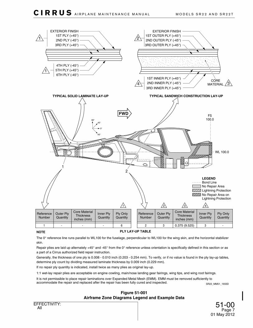
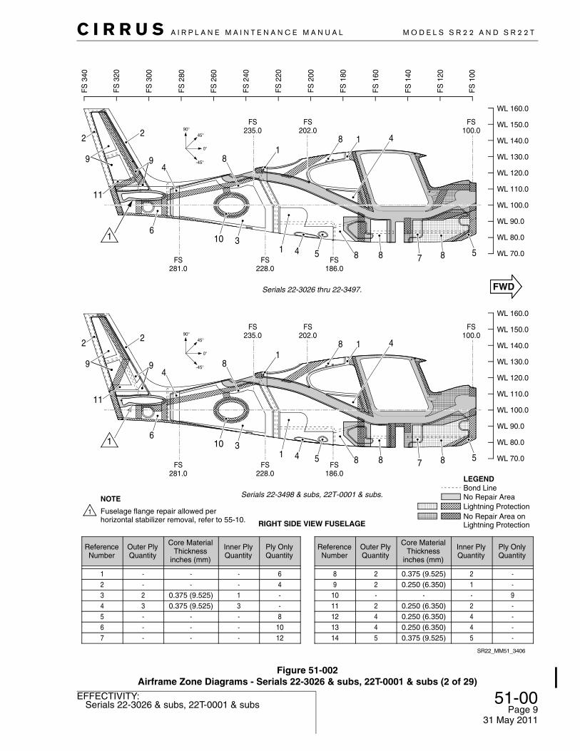
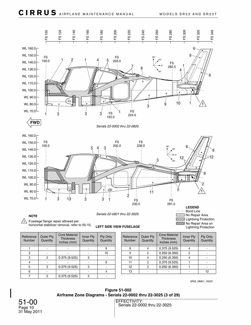
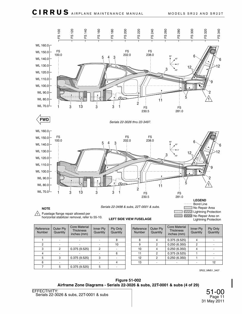
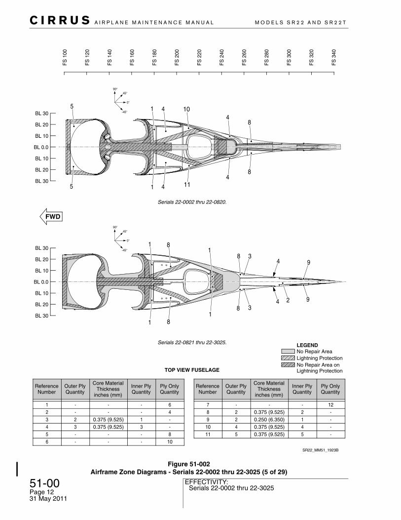
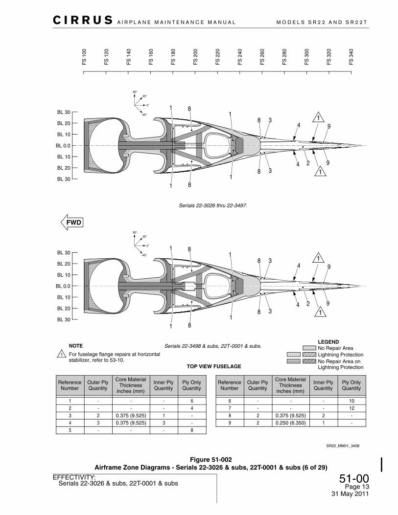
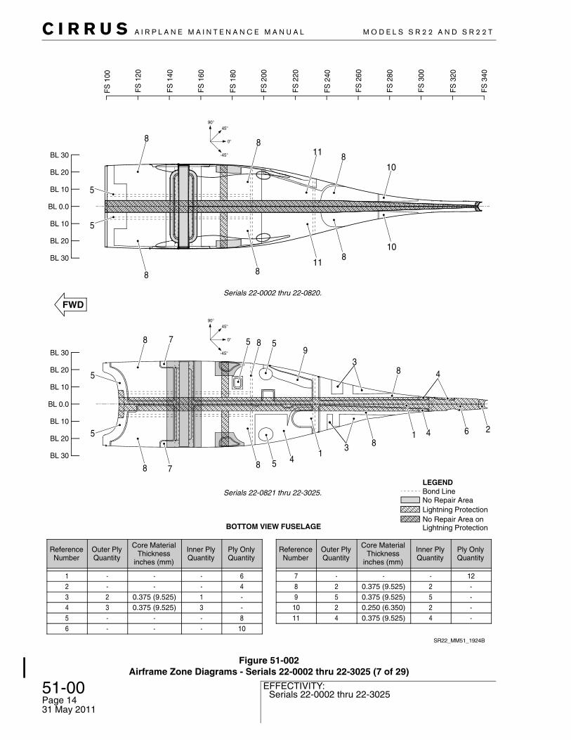
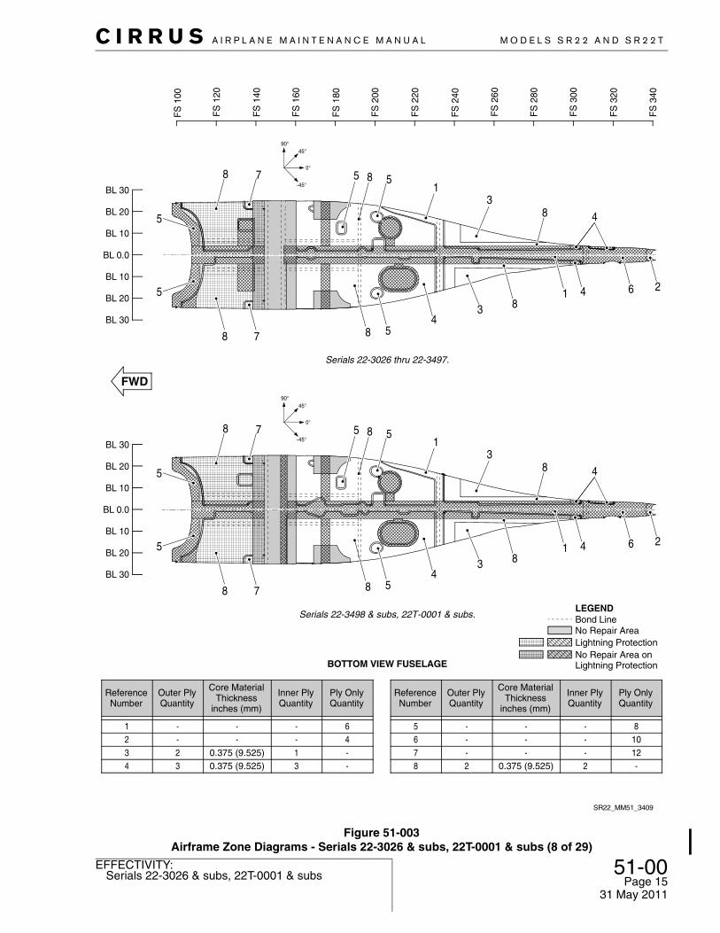
E. Airframe Zone Diagrams (See Figure 51-001), (See Figure 51-002)
To aid the repair technician in determining the structural criticality of each damage site, the following zone diagrams identify original ply lay-up sections, composite repair zones, no-repair zones, and areas with embedded expanded metal mesh (EMM) used in the electrical bonding of the aircraft.
CAUTION: Contact Cirrus Design before attempting to repair any composite structure within the shaded no-repair zones. (Refer to AMM-Intro-00)
C I R R U S A I R P L A N E M A I N T E N A N C E M A N U A L M O D E L S S R 2 2 A N D S R 2 2 T
51-00Page 7All
EFFECTIVITY:
Figure 51-001Airframe Zone Diagrams Legend and Example Data
NOTE
EXTERIOR FINISH
COREMATERIAL
3RD INNER PLY (+45°)
2ND INNER PLY (-45°)1ST INNER PLY (+45°)
3RD OUTER PLY (+45°)2ND OUTER PLY (-45°)1ST OUTER PLY (+45°)
SR22_MM51_1933D
2
TYPICAL SANDWICH CONSTRUCTION LAY-UP
PLY LAY-UP TABLE
EXTERIOR FINISH
6TH PLY (-45°)5TH PLY (+45°)4TH PLY (-45°)
3RD PLY (+45°)2ND PLY (-45°)1ST PLY (+45°)
TYPICAL SOLID LAMINATE LAY-UP
1
6---1
Ply OnlyQuantity
Inner PlyQuantity
Core MaterialThickness
inches (mm)
Outer PlyQuantity
ReferenceNumber
-30.375 (9.525)32
Ply OnlyQuantity
Inner PlyQuantity
Core MaterialThickness
inches (mm)
Outer PlyQuantity
ReferenceNumber
FS100.0
WL 100.0
Lightning ProtectionNo Repair Area onLightning Protection
No Repair Area
LEGENDBond Line
1:1 wet-lay repair plies are acceptable on engine cowling, main/nose landing gear fairings, wing tips, and wing root fairings.
Repair plies are laid up alternately +45° and -45° from the 0° reference unless orientation is specifically defined in this section or asa part of a Cirrus authorized field repair instruction.
The 0° reference line runs parallel to WL100 for the fuselage, perpendicular to WL100 for the wing skin, and the horizontal stabilizerskin.
If no repair ply quantity is indicated, install twice as many plies as original lay-up.
Generally, the thickness of one ply is 0.008 - 0.010 inch (0.203 - 0.254 mm). To verify, or if no value is found in the ply lay-up tables,determine ply count by dividing measured laminate thickness by 0.009 inch (0.229 mm).
It is not permissible to place repair laminations over Expanded Metal Mesh (EMM). EMM must be removed sufficiently toaccommodate the repair and replaced after the repair has been fully cured and inspected.
01 May 2012

51-00Page 8
Serials 22-0002 thru 22-3025EFFECTIVITY:
C I R R U S A I R P L A N E M A I N T E N A N C E M A N U A L M O D E L S S R 2 2 A N D S R 2 2 T
31 May 2011
Figure 51-002Airframe Zone Diagrams - Serials 22-0002 thru 22-3025 (1 of 29)
--9--
42-12
0.250 (6.350)0.250 (6.350)
-0.250 (6.350)0.375 (9.525)
42-22
12111098
Ply OnlyQuantity
Inner PlyQuantity
Core MaterialThickness
inches (mm)
Outer PlyQuantity
ReferenceNumber
108--46
--31--
--
0.375 (9.525)0.375 (9.525)
--
--32--
654321
Ply OnlyQuantity
Inner PlyQuantity
Core MaterialThickness
inches (mm)
Outer PlyQuantity
ReferenceNumber
FS 226.0
FS 296.0
FS 260.0
FS 256.0
FS
340
FS
320
FS
300
FS
280
FS
260
FS
240
FS
220
FS
200
FS
180
FS
160
FS
140
FS
120
FS
100
12
4
5
111
2
11
2
6 12 11 8
5 11 11 511
6 5
13141
FS 282.5
FS 191.0
FS 202.0
SR22_MM51_1921C
FS 100.0
FS228.0
FS281.0
FS235.0
8
758
9
FS186.0
FS202.0
FS100.0
4181
2
9
2
11
6
4
10 31 4 5 8 8
Serials 22-0821 thru 22-3025.
RIGHT SIDE VIEW FUSELAGE
12---7-40.250 (6.350)413-50.375 (9.525)514
WL 140.0
WL 130.0
WL 120.0
WL 110.0
WL 100.0
WL 90.0
WL 80.0
WL 70.0
WL 150.0
WL 160.0
Serials 22-0002 thru 22-0820.
WL 140.0
WL 130.0
WL 120.0
WL 110.0
WL 100.0
WL 90.0
WL 80.0
WL 70.0
WL 150.0
WL 160.0
Lightning ProtectionNo Repair Area onLightning Protection
No Repair Area
LEGENDBond Line
45°
0°
-45°
90°
45°
0°
-45°
90°
Fuselage flange repair allowed perhorizontal stabilizer removal, refer to 55-10.
NOTE
C I R R U S A I R P L A N E M A I N T E N A N C E M A N U A L M O D E L S S R 2 2 A N D S R 2 2 T
51-00Page 9Serials 22-3026 & subs, 22T-0001 & subs
EFFECTIVITY:
Figure 51-002Airframe Zone Diagrams - Serials 22-3026 & subs, 22T-0001 & subs (2 of 29)
45°
0°
-45°
90°
SR22_MM51_3406
--9--
42-12
0.250 (6.350)0.250 (6.350)
-0.250 (6.350)0.375 (9.525)
42-22
12111098
Ply OnlyQuantity
Inner PlyQuantity
Core MaterialThickness
inches (mm)
Outer PlyQuantity
ReferenceNumber
108--46
--31--
--
0.375 (9.525)0.375 (9.525)
--
--32--
654321
Ply OnlyQuantity
Inner PlyQuantity
Core MaterialThickness
inches (mm)
Outer PlyQuantity
ReferenceNumber
FS
340
FS
320
FS
300
FS
280
FS
260
FS
240
FS
220
FS
200
FS
180
FS
160
FS
140
FS
120
FS
100
FS228.0
FS281.0
FS235.0
8
7 58
9
FS186.0
FS202.0
FS100.0
4181
2
9
2
11
6
4
10 31 4 5 8 8
Serials 22-3026 thru 22-3497.
RIGHT SIDE VIEW FUSELAGE
12---7-40.250 (6.350)413-50.375 (9.525)514
WL 140.0
WL 130.0
WL 120.0
WL 110.0
WL 100.0
WL 90.0
WL 80.0
WL 70.0
WL 150.0
WL 160.0
Lightning ProtectionNo Repair Area onLightning Protection
LEGENDBond Line
45°
0°
-45°
90°
FS228.0
FS281.0
FS235.0
8
7 58
9
FS186.0
FS202.0
FS100.0
4181
2
9
2
11
6
4
10 31 4 5 8 8
Serials 22-3498 & subs, 22T-0001 & subs.
WL 140.0
WL 130.0
WL 120.0
WL 110.0
WL 100.0
WL 90.0
WL 80.0
WL 70.0
WL 150.0
WL 160.0
No Repair Area
Fuselage flange repair allowed perhorizontal stabilizer removal, refer to 55-10.
NOTE
31 May 2011
51-00Page 10
Serials 22-0002 thru 22-3025EFFECTIVITY:
C I R R U S A I R P L A N E M A I N T E N A N C E M A N U A L M O D E L S S R 2 2 A N D S R 2 2 T
31 May 2011
Figure 51-002Airframe Zone Diagrams - Serials 22-0002 thru 22-3025 (3 of 29)
FS224.0FS
193.0
FS203.0
FS100.0
FS282.5
FS281.0
FS230.5
FS202.0
FS100.0
FS238.0
-----
11424
0.250 (6.350)0.375 (9.525)0.250 (6.350)0.250 (6.350)0.375 (9.525)
22424
12111098
Ply OnlyQuantity
Inner PlyQuantity
Core MaterialThickness
inches (mm)
Outer PlyQuantity
ReferenceNumber
4-6-
108
-3-2--
-0.375 (9.525)
-0.375 (9.525)
--
-3-2--
654321
Ply OnlyQuantity
Inner PlyQuantity
Core MaterialThickness
inches (mm)
Outer PlyQuantity
ReferenceNumber
LEFT SIDE VIEW FUSELAGE
-50.375 (9.525)5712---13
Serials 22-0821 thru 22-3025.
Serials 22-0002 thru 22-0820.
SR22_MM51_1922C
1 2
31 3 3 13 9 10 1
6
9
6
511
FS
100
FS
120
FS
140
FS
160
FS
180
FS
200
FS
220
FS
240
FS
260
FS
280
FS
300
FS
320
FS
340
487
4
4
3
5 3
115
2133131 3
2
6
12
6
9
12
Lightning ProtectionNo Repair Area onLightning Protection
No Repair Area
LEGENDBond Line
WL 140.0
WL 130.0
WL 120.0
WL 110.0
WL 100.0
WL 90.0
WL 80.0
WL 70.0
WL 150.0
WL 160.0
WL 140.0
WL 130.0
WL 120.0
WL 110.0
WL 100.0
WL 90.0
WL 80.0
WL 70.0
WL 150.0
WL 160.0
Fuselage flange repair allowed perhorizontal stabilizer removal, refer to 55-10.
NOTE
C I R R U S A I R P L A N E M A I N T E N A N C E M A N U A L M O D E L S S R 2 2 A N D S R 2 2 T
51-00Page 11Serials 22-3026 & subs, 22T-0001 & subs
EFFECTIVITY:
Figure 51-002Airframe Zone Diagrams - Serials 22-3026 & subs, 22T-0001 & subs (4 of 29)
45°
0°
-45°
90°
FS281.0
FS230.5
FS202.0
FS100.0
FS238.0
SR22_MM51_3407
FS
100
FS
120
FS
140
FS
160
FS
180
FS
200
FS
220
FS
240
FS
260
FS
280
FS
300
FS
320
FS
340
FS281.0
FS230.5
FS202.0
FS100.0
FS238.0
4
3
5 3
115
2133131 3
2
6
12
6
9
12
Lightning ProtectionNo Repair Area onLightning Protection
LEGEND
-----
11424
0.250 (6.350)0.375 (9.525)0.250 (6.350)0.250 (6.350)0.375 (9.525)
22424
12111098
Ply OnlyQuantity
Inner PlyQuantity
Core MaterialThickness
inches (mm)
Outer PlyQuantity
ReferenceNumber
4-6-
108
-3-2--
-0.375 (9.525)
-0.375 (9.525)
--
-3-2--
654321
Ply OnlyQuantity
Inner PlyQuantity
Core MaterialThickness
inches (mm)
Outer PlyQuantity
ReferenceNumber
LEFT SIDE VIEW FUSELAGE
-50.375 (9.525)5712---13
WL 140.0
WL 130.0
WL 120.0
WL 110.0
WL 100.0
WL 90.0
WL 80.0
WL 70.0
WL 150.0
WL 160.0
Bond LineSerials 22-3498 & subs, 22T-0001 & subs.
Serials 22-3026 thru 22-3497.
45°
0°
-45°
90°
WL 140.0
WL 130.0
WL 120.0
WL 110.0
WL 100.0
WL 90.0
WL 80.0
WL 70.0
WL 150.0
WL 160.0
No Repair Area
Fuselage flange repair allowed perhorizontal stabilizer removal, refer to 55-10.
NOTE
4
3
5 3
115
2133131 3
2
6
12
6
9
12
31 May 2011
51-00Page 12
Serials 22-0002 thru 22-3025EFFECTIVITY:
C I R R U S A I R P L A N E M A I N T E N A N C E M A N U A L M O D E L S S R 2 2 A N D S R 2 2 T
31 May 2011
Figure 51-002Airframe Zone Diagrams - Serials 22-0002 thru 22-3025 (5 of 29)
FS
100
1 81
8 3
381
81
4
4
2 9
9
Serials 22-0002 thru 22-0820.
5 1 4 104
8
84
11415
SR22_MM51_1923B
Lightning Protection No Repair Area onLightning Protection
No Repair AreaLEGEND
---
12
412-
0.375 (9.525)0.250 (6.350)0.375 (9.525)
-
422-
1110987
Ply OnlyQuantity
Inner PlyQuantity
Core MaterialThickness
inches (mm)
Outer PlyQuantity
ReferenceNumber
8--46
-31--
-0.375 (9.525)0.375 (9.525)
--
-32--
54321
Ply OnlyQuantity
Inner PlyQuantity
Core MaterialThickness
inches (mm)
Outer PlyQuantity
ReferenceNumber
10---6-50.375 (9.525)5
BL 0.0
BL 10
BL 20
BL 30
BL 10
BL 20
BL 30
BL 0.0
BL 10
BL 20
BL 30
BL 10
BL 20
BL 30
Serials 22-0821 thru 22-3025.
TOP VIEW FUSELAGE
FS
340
FS
320
FS
300
FS
280
FS
260
FS
240
FS
220
FS
200
FS
180
FS
160
FS
140
FS
120
45°
0°
-45°
90°
45°
0°
-45°
90°
C I R R U S A I R P L A N E M A I N T E N A N C E M A N U A L M O D E L S S R 2 2 A N D S R 2 2 T
51-00Page 13Serials 22-3026 & subs, 22T-0001 & subs
EFFECTIVITY:
Figure 51-002Airframe Zone Diagrams - Serials 22-3026 & subs, 22T-0001 & subs (6 of 29)
SR22_MM51_3408
Lightning Protection No Repair Area onLightning Protection
No Repair Area
LEGEND
--
12
12-
0.250 (6.350)0.375 (9.525)
-
22-
987
Ply OnlyQuantity
Inner PlyQuantity
Core MaterialThickness
inches (mm)
Outer PlyQuantity
ReferenceNumber
8--46
-31--
-0.375 (9.525)0.375 (9.525)
--
-32--
54321
Ply OnlyQuantity
Inner PlyQuantity
Core MaterialThickness
inches (mm)
Outer PlyQuantity
ReferenceNumber
10---6
BL 0.0
BL 10
BL 20
BL 30
BL 10
BL 20
BL 301 8
18 3
381
81
4
4
2 9
9
Serials 22-3026 thru 22-3497.
FS
100
FS
120
FS
140
FS
160
FS
180
FS
200
FS
220
FS
240
FS
260
FS
280
FS
300
FS
320
FS
340
TOP VIEW FUSELAGE
45°
0°
-45°
90°
For fuselage flange repairs at horizontalstabilizer, refer to 53-10.
NOTE
1 81
8 3
381
81
4
4
2 9
9
BL 0.0
BL 10
BL 20
BL 30
BL 10
BL 20
BL 30
Serials 22-3498 & subs, 22T-0001 & subs.
45°
0°
-45°
90°
31 May 2011
51-00Page 14
Serials 22-0002 thru 22-3025EFFECTIVITY:
C I R R U S A I R P L A N E M A I N T E N A N C E M A N U A L M O D E L S S R 2 2 A N D S R 2 2 T
31 May 2011
Figure 51-002Airframe Zone Diagrams - Serials 22-0002 thru 22-3025 (7 of 29)
SR22_MM51_1924B
8
5
8
5
8
811
118
10
810
FS
100
FS
120
FS
140
FS
160
FS
180
FS
200
FS
220
FS
240
FS
260
FS
280
FS
300
FS
320
FS
340
8
5
8
5
8
8
1
93
18
26
4
4
3
8
5
5 5
47
7
Lightning ProtectionNo Repair Area onLightning Protection
No Repair Area
LEGEND
---
12
252-
0.250 (6.350)0.375 (9.525)0.375 (9.525)
-
252-
1110987
Ply OnlyQuantity
Inner PlyQuantity
Core MaterialThickness
inches (mm)
Outer PlyQuantity
ReferenceNumber
8--46
-31--
-0.375 (9.525)0.375 (9.525)
--
-32--
54321
Ply OnlyQuantity
Inner PlyQuantity
Core MaterialThickness
inches (mm)
Outer PlyQuantity
ReferenceNumber
BOTTOM VIEW FUSELAGE
10---6-40.375 (9.525)4
BL 0.0
BL 10
BL 20
BL 30
BL 10
BL 20
BL 30
BL 0.0
BL 10
BL 20
BL 30
BL 10
BL 20
BL 30
Bond LineSerials 22-0821 thru 22-3025.
Serials 22-0002 thru 22-0820.
45°
0°
-45°
90°
45°
0°
-45°
90°
C I R R U S A I R P L A N E M A I N T E N A N C E M A N U A L M O D E L S S R 2 2 A N D S R 2 2 T
51-00Page 15Serials 22-3026 & subs, 22T-0001 & subs
EFFECTIVITY:
Figure 51-003Airframe Zone Diagrams - Serials 22-3026 & subs, 22T-0001 & subs (8 of 29)
8
83
3
8
8
8
81
3
18
26
4
4
3
8
5
47
7
SR22_MM51_3409
FS
100
FS
120
FS
140
FS
160
FS
180
FS
200
FS
220
FS
240
FS
260
FS
280
FS
300
FS
320
FS
340
Lightning ProtectionNo Repair Area onLightning Protection
No Repair Area
LEGEND
-12
2-
0.375 (9.525)-
2-
87
Ply OnlyQuantity
Inner PlyQuantity
Core MaterialThickness
inches (mm)
Outer PlyQuantity
ReferenceNumber
8
--46 -
31-- -
0.375 (9.525)0.375 (9.525)
-- -
32-- 5
4321
Ply OnlyQuantity
Inner PlyQuantity
Core MaterialThickness
inches (mm)
Outer PlyQuantity
ReferenceNumber
BOTTOM VIEW FUSELAGE
10---6
BL 0.0
BL 10
BL 20
BL 30
BL 10
BL 20
BL 30
Bond Line
Serials 22-3026 thru 22-3497.
45°
0°
-45°
90°
5
5
5
5
5
5
5
5
8
8
7
7 5
48
8
45°
0°
-45°
90°
1
BL 0.0
BL 10
BL 20
BL 30
BL 10
BL 20
BL 30
Serials 22-3498 & subs, 22T-0001 & subs.
1 26
4
4
31 May 2011
51-00Page 16
Serials 22-0002 thru 22-2437EFFECTIVITY:
C I R R U S A I R P L A N E M A I N T E N A N C E M A N U A L M O D E L S S R 2 2 A N D S R 2 2 T
31 May 2011
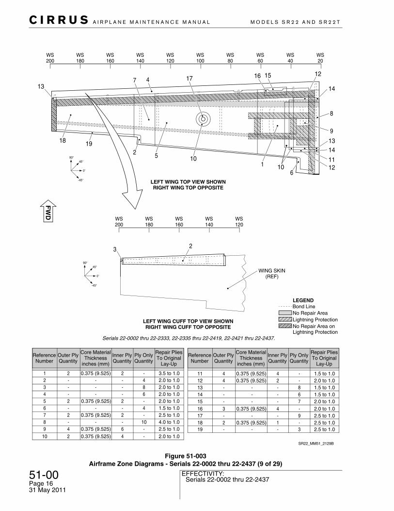
Figure 51-003Airframe Zone Diagrams - Serials 22-0002 thru 22-2437 (9 of 29)
SR22_MM51_2129B
LEFT WING CUFF TOP VIEW SHOWNRIGHT WING CUFF TOP OPPOSITE
WS200
WS180
WS160
WS140
WS120
45°
0°
-45°
90°
3 2
WING SKIN(REF)
LEFT WING TOP VIEW SHOWNRIGHT WING TOP OPPOSITE
1211
1413
9
8
14
121516174713
18 192 5 10
1 106
WS200
WS180
WS160
WS140
WS120
WS100
WS80
WS60
WS40
WS20
45°
0°
-45°
90°
-20.375 (9.525)21
Ply OnlyQuantity
Inner PlyQuantity
Core MaterialThickness
inches (mm)
Outer PlyQuantity
ReferenceNumber
4---28---36---4
Repair PliesTo Original
Lay-Up
Ply OnlyQuantity
Inner PlyQuantity
Core MaterialThickness
inches (mm)
Outer PlyQuantity
ReferenceNumber
1112
-44
13-24
148---
15
Repair PliesTo Original
Lay-Up
6---
167---
17-40.375 (9.525)3
18
-20.375 (9.525)25
9---
19
3.5 to 1.02.0 to 1.02.0 to 1.02.0 to 1.02.0 to 1.0
1.5 to 1.02.0 to 1.01.5 to 1.01.5 to 1.02.0 to 1.02.0 to 1.02.5 to 1.0
-10.375 (9.525)2 2.5 to 1.03--- 2.5 to 1.0
0.375 (9.525)0.375 (9.525)
-4
2--
2-
876
910----64
1.5 to 1.02.5 to 1.04.0 to 1.02.5 to 1.0
0.375 (9.525)
0.375 (9.525)10 -42 2.0 to 1.00.375 (9.525)
Bond Line
No Repair Area onLightning Protection
No Repair Area Lightning Protection
LEGEND
Serials 22-0002 thru 22-2333, 22-2335 thru 22-2419, 22-2421 thru 22-2437.
C I R R U S A I R P L A N E M A I N T E N A N C E M A N U A L M O D E L S S R 2 2 A N D S R 2 2 T
51-00Page 17Serials 22-0002 thru 22-2437
EFFECTIVITY:
31 May 2011
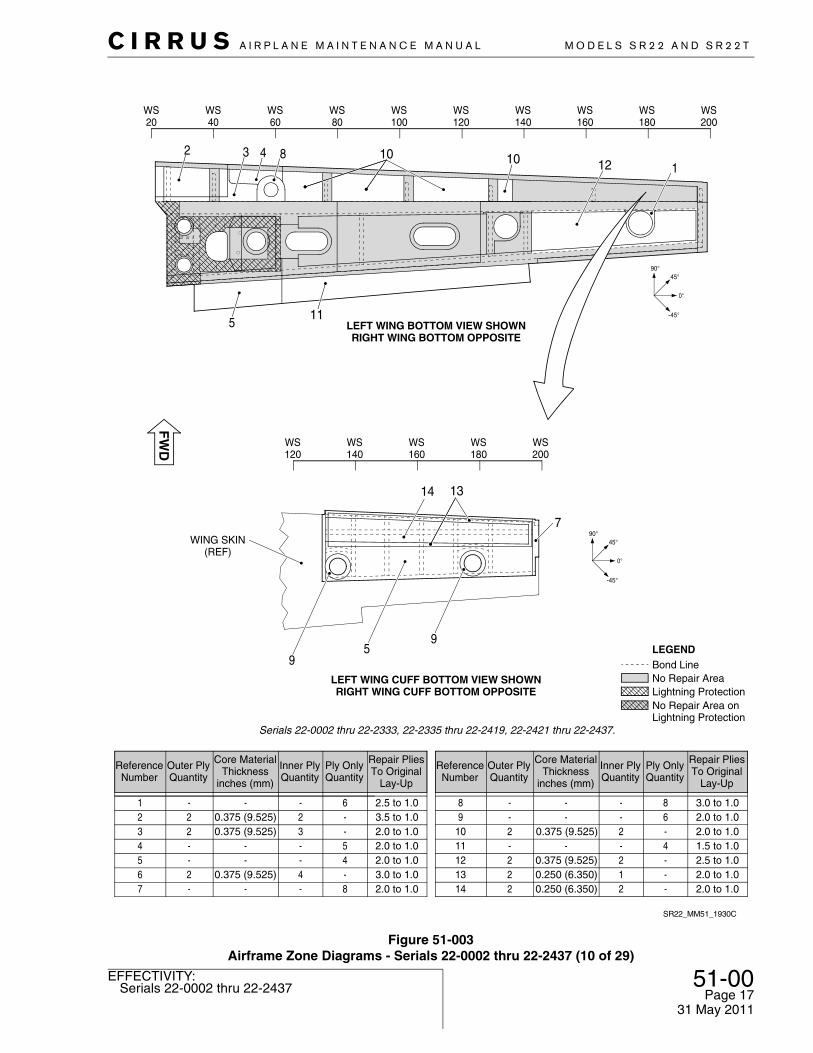
Figure 51-003Airframe Zone Diagrams - Serials 22-0002 thru 22-2437 (10 of 29)
LEFT WING BOTTOM VIEW SHOWNRIGHT WING BOTTOM OPPOSITE
5
3 4 8 10
11
12 12
WS20
WS40
WS60
WS80
WS100
WS120
WS140
WS160
WS180
WS200
Lightning Protection
Bond Line
No Repair Area onLightning Protection
No Repair Area
LEGEND
SR22_MM51_1930C
WING SKIN(REF)
14 13
7
59
9LEFT WING CUFF BOTTOM VIEW SHOWNRIGHT WING CUFF BOTTOM OPPOSITE
45°
0°
-45°
90°
WS200
WS180
WS160
WS140
WS120
-6
20.375 (9.525)221
Ply OnlyQuantity
Inner PlyQuantity
Core MaterialThickness
inches (mm)
Outer PlyQuantity
ReferenceNumber
-30.375 (9.525)235---44---5-40.375 (9.525)268---7
8---86---9
Repair PliesTo Original
Lay-Up
-4
2--
2-
131211
Ply OnlyQuantity
Inner PlyQuantity
Core MaterialThickness
inches (mm)
Outer PlyQuantity
ReferenceNumber
14-12-22
1.5 to 1.0
Repair PliesTo Original
Lay-Up
2.5 to 1.03.5 to 1.02.0 to 1.02.0 to 1.02.0 to 1.03.0 to 1.02.0 to 1.0
3.0 to 1.02.0 to 1.0
2.5 to 1.02.0 to 1.02.0 to 1.0
---
0.375 (9.525)0.250 (6.350)0.250 (6.350)
-20.375 (9.525)210 2.0 to 1.0
90°
-45°
0°
45°
10
Serials 22-0002 thru 22-2333, 22-2335 thru 22-2419, 22-2421 thru 22-2437.

51-00Page 18
Serials 22-2438 & subs, 22T-0001 & subsEFFECTIVITY:
C I R R U S A I R P L A N E M A I N T E N A N C E M A N U A L M O D E L S S R 2 2 A N D S R 2 2 T
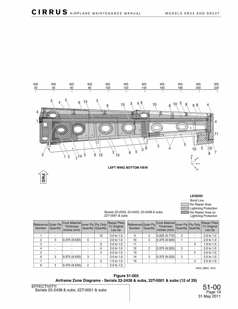
Figure 51-003Airframe Zone Diagrams - Serials 22-2438 & subs, 22T-0001 & subs (11 of 29)
617
1012 11 12 11 13 15 13 6
13
16 12 11 4
98
310
15
10 11
7
15
1215
1445
LEFT WING TOP VIEW SHOWNRIGHT WING TOP OPPOSITE
Lightning Protection
Bond Line
No Repair Area onLightning Protection
No Repair Area
LEGEND
SR22_MM51_2632A
Lightning Protection
Bond Line
No Repair Area onLightning Protection
No Repair Area
LEGEND
Serials 22-2334, 22-2420, 22-2438 & subs,22T-0001 & subs.
WS20
WS40
WS60
WS80
WS120
WS100
WS140
WS160
WS180
WS200
WS220
45°
0°
-45°
90°
-3 1.5 to 1.080.375 (9.525)4142 1.5 to 1.0---
-4 2.0 to 1.040.375 (9.525)4-5 2.0 to 1.060.335 (8.509)676 1.5 to 1.0----7 2.0 to 1.020.375 (9.525)4-8 1.5 to 1.010.375 (9.525)4
3---10 1.5 to 1.0-10.375 (9.525)211 2.0 to 1.0-20.375 (9.525)212 2.0 to 1.04---13 2.0 to 1.06---14 2.0 to 1.08---15 2.0 to 1.0-10.125 (3.175)216 1.5 to 1.0-30.375 (9.525)217 1.5 to 1.0
121
Ply OnlyQuantity
Inner PlyQuantity
Core MaterialThickness
inches (mm)
Outer PlyQuantity
ReferenceNumber
5---9
Repair PliesTo Original
Lay-Up
Ply OnlyQuantity
Inner PlyQuantity
Core MaterialThickness
inches (mm)
Outer PlyQuantity
ReferenceNumber
Repair PliesTo Original
Lay-Up
1.5 to 1.0 1.5 to 1.0---
31 May 2011
C I R R U S A I R P L A N E M A I N T E N A N C E M A N U A L M O D E L S S R 2 2 A N D S R 2 2 T
51-00Page 19Serials 22-2438 & subs, 22T-0001 & subs
EFFECTIVITY:
31 May 2011
Figure 51-003Airframe Zone Diagrams - Serials 22-2438 & subs, 22T-0001 & subs (12 of 29)
WS220
WS200
WS180
WS160
WS120
WS140
WS100
WS80
WS60
WS40
WS20
LEFT WING BOTTOM VIEW
Lightning Protection
Bond Line
No Repair Area onLightning Protection
No Repair Area
LEGEND
SR22_MM51_2616
45°
0°
-45°
90°
Serials 22-2334, 22-2420, 22-2438 & subs,22T-0001 & subs.
49 88 85943153 4
56
8513
1
4
2 1 3 714 3
5813
36 12
105
4383
7108
5
4
11
10 10
83 2.0 to 1.0----2 2.0 to 1.050.375 (9.525)3
64 2.0 to 1.0---45 2.0 to 1.0----6 2.0 to 1.030.375 (9.525)337 1.5 to 1.0----8 2.0 to 1.020.375 (9.525)2
121 2.0 to 1.0----10.375 (9.525)210 2.0 to 1.09---11 1.0 to 1.0-30.375 (9.525)212 2.0 to 1.05---13 2.0 to 1.0
-20.225 (5.715)29 2.0 to 1.0
Ply OnlyQuantity
Inner PlyQuantity
Core MaterialThickness
inches (mm)
Outer PlyQuantity
ReferenceNumber
Repair PliesTo Original
Lay-Up
Ply OnlyQuantity
Inner PlyQuantity
Core MaterialThickness
inches (mm)
Outer PlyQuantity
ReferenceNumber
Repair PliesTo Original
Lay-Up
-30.375 (9.525)314 2.5 to 1.04---15 2.5 to 1.0
51-00Page 20
Serials 22-2438 & subs, 22T-0001 & subsEFFECTIVITY:
C I R R U S A I R P L A N E M A I N T E N A N C E M A N U A L M O D E L S S R 2 2 A N D S R 2 2 T
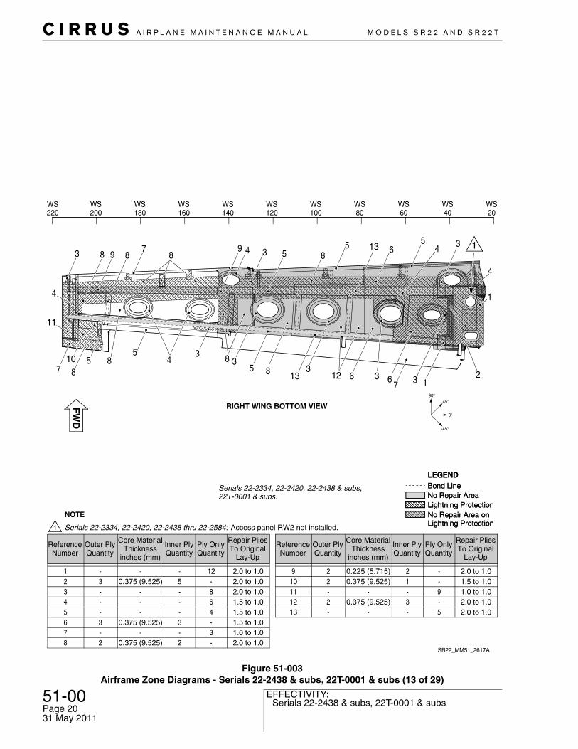
Figure 51-003Airframe Zone Diagrams - Serials 22-2438 & subs, 22T-0001 & subs (13 of 29)
3
7
38 9 8
78
1
435
61355 849
5 8 45
833
510
38
4
11
8 2137
613 12 6 3
RIGHT WING BOTTOM VIEW
Lightning Protection
Bond Line
No Repair Area onLightning Protection
No Repair Area
LEGEND
SR22_MM51_2617A
Lightning Protection
Bond Line
No Repair Area onLightning Protection
No Repair Area
LEGEND
Serials 22-2334, 22-2420, 22-2438 & subs,22T-0001 & subs.
45°
0°
-45°
90°
WS20
WS40
WS60
WS80
WS120
WS100
WS140
WS160
WS180
WS200
WS220
NOTE
Serials 22-2334, 22-2420, 22-2438 thru 22-2584: Access panel RW2 not installed.
4
83 2.0 to 1.0----2 2.0 to 1.050.375 (9.525)3
64 1.5 to 1.0---45 1.5 to 1.0----6 1.5 to 1.030.375 (9.525)337 1.0 to 1.0----8 2.0 to 1.020.375 (9.525)2
121 2.0 to 1.0----10.375 (9.525)210 1.5 to 1.09---11 1.0 to 1.0-30.375 (9.525)212 2.0 to 1.05---13 2.0 to 1.0
-20.225 (5.715)29 2.0 to 1.0
Ply OnlyQuantity
Inner PlyQuantity
Core MaterialThickness
inches (mm)
Outer PlyQuantity
ReferenceNumber
Repair PliesTo Original
Lay-Up
Ply OnlyQuantity
Inner PlyQuantity
Core MaterialThickness
inches (mm)
Outer PlyQuantity
ReferenceNumber
Repair PliesTo Original
Lay-Up
31 May 2011
C I R R U S A I R P L A N E M A I N T E N A N C E M A N U A L M O D E L S S R 2 2 A N D S R 2 2 T
51-00Page 21All
EFFECTIVITY:
31 May 2011
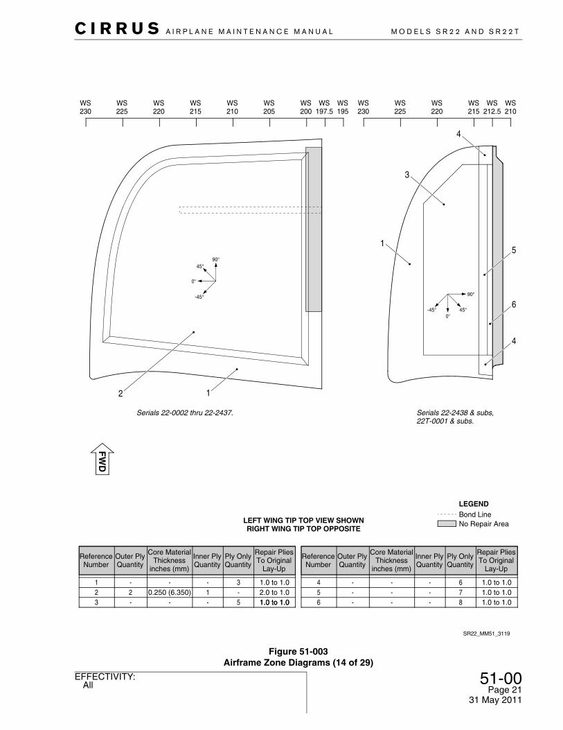
Figure 51-003Airframe Zone Diagrams (14 of 29)
45°
0°
-45°
90°
LEFT WING TIP TOP VIEW SHOWNRIGHT WING TIP TOP OPPOSITE
Serials 22-0002 thru 22-2437.
SR22_MM51_3119
12
Bond LineNo Repair Area
LEGEND
45°0°
-45°
90°
WS210
WS220
WS230
WS212.5
WS225
WS215
1
3
4
5
6
4
WS200
WS210
WS220
WS230
WS197.5
WS195
WS205
WS215
WS225
Serials 22-2438 & subs,22T-0001 & subs.
64
1.0 to 1.0
---
53 1.0 to 1.0----2 2.0 to 1.010.250 (6.350)231 1.0 to 1.0---
Ply OnlyQuantity
Inner PlyQuantity
Core MaterialThickness
inches (mm)
Outer PlyQuantity
ReferenceNumber
Repair PliesTo Original
Lay-Up
75 1.0 to 1.0---86 1.0 to 1.0---
Ply OnlyQuantity
Inner PlyQuantity
Core MaterialThickness
inches (mm)
Outer PlyQuantity
ReferenceNumber
Repair PliesTo Original
Lay-Up
1.0 to 1.0

51-00Page 22
AllEFFECTIVITY:
C I R R U S A I R P L A N E M A I N T E N A N C E M A N U A L M O D E L S S R 2 2 A N D S R 2 2 T
Figure 51-003Airframe Zone Diagrams (15 of 29)
45°
0°
-45°
90°
Serials 22-0002 thru 22-2437.
Bond LineNo Repair Area
LEGEND
WS210
WS220
WS230
WS212.5
WS225
WS215
WS200
WS210
WS220
WS230
WS197.5
WS195
WS205
WS215
WS225
43 1.0 to 1.0----2 2.0 to 1.010.250 (6.350)2
84 1.0 to 1.0---
75 1.0 to 1.0---31 1.0 to 1.0---
Ply OnlyQuantity
Inner PlyQuantity
Core MaterialThickness
inches (mm)
Outer PlyQuantity
ReferenceNumber
Repair PliesTo Original
Lay-Up
57 1.0 to 1.0---66 1.0 to 1.0---
Ply OnlyQuantity
Inner PlyQuantity
Core MaterialThickness
inches (mm)
Outer PlyQuantity
ReferenceNumber
Repair PliesTo Original
Lay-Up
45°
0°
-45°
90°
45°0°
-45°
90°
LEFT WING TIP BOTTOM VIEW SHOWNRIGHT WING TIP BOTTOM OPPOSITE
SR22_MM51_3121
1 2 3 3
4
5
6
7
4
4
Serials 22-2438 & subs,22T-0001 & subs.
31 May 2011
C I R R U S A I R P L A N E M A I N T E N A N C E M A N U A L M O D E L S S R 2 2 A N D S R 2 2 T
51-00Page 23All
EFFECTIVITY:
31 May 2011
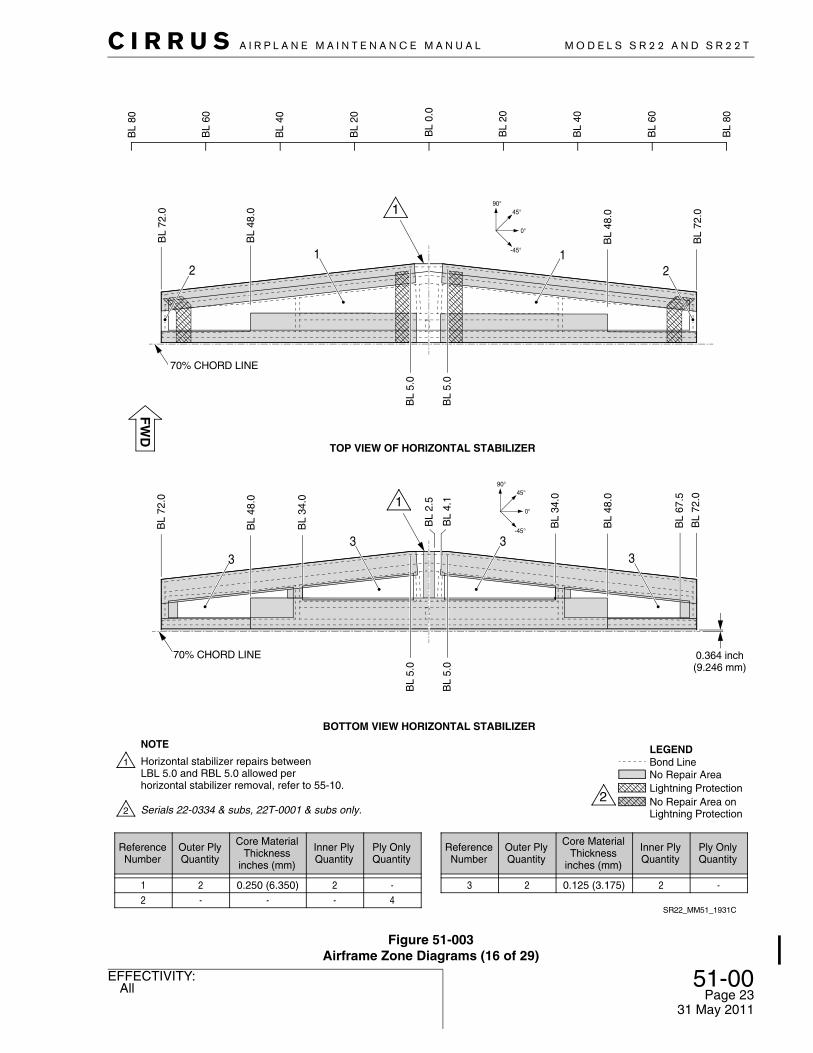
Figure 51-003Airframe Zone Diagrams (16 of 29)
Lightning ProtectionNo Repair Area onLightning Protection
No Repair Area
LEGENDBond Line
BL
34.0
BL
5.0
BL
80
BL
60
BL
40
BL
20
BL
80
BL
60
BL
40
BL
20
BL
0.0
2
TOP VIEW OF HORIZONTAL STABILIZER
SR22_MM51_1931C
BL
72.0
BL
48.0
BL
72.0
BL
48.0
70% CHORD LINE
1 12
70% CHORD LINE
BL
72.0
BL
48.0
BL
34.0
BL
72.0
3 333
BL
5.0
BL
48.0
BL
4.1
BL
2.5
BL
67.5
BOTTOM VIEW HORIZONTAL STABILIZER
0.364 inch(9.246 mm)
ReferenceNumber
Outer PlyQuantity
Core MaterialThickness
inches (mm)
Inner PlyQuantity
Ply OnlyQuantity
12
2-
0.250 (6.350)-
2-
-4
ReferenceNumber
Outer PlyQuantity
Core MaterialThickness
inches (mm)
Inner PlyQuantity
Ply OnlyQuantity
3 2 0.125 (3.175) 2 -
45°
0°
-45°
90°
45°
0°
-45°
90°
Horizontal stabilizer repairs betweenLBL 5.0 and RBL 5.0 allowed per horizontal stabilizer removal, refer to 55-10.
NOTE
BL
5.0
BL
5.0
Serials 22-0334 & subs, 22T-0001 & subs only.
51-00Page 24
Serials 22-0002 thru 22-0835EFFECTIVITY:
C I R R U S A I R P L A N E M A I N T E N A N C E M A N U A L M O D E L S S R 2 2 A N D S R 2 2 T
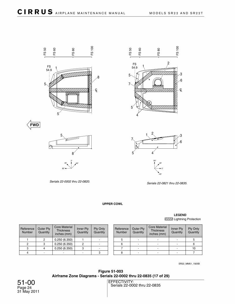
Figure 51-003Airframe Zone Diagrams - Serials 22-0002 thru 22-0835 (17 of 29)
5
5
5
8
1
8
FS54.9
SR22_MM51_1925B
FS
50
FS
60
FS
80
FS
100
ReferenceNumber
Outer PlyQuantity
Core MaterialThickness
inches (mm)
Inner PlyQuantity
Ply OnlyQuantity
1234
234-
0.250 (6.350)0.250 (6.350)0.250 (6.350)
-
123-
---3
ReferenceNumber
Outer PlyQuantity
Core MaterialThickness
inches (mm)
Inner PlyQuantity
Ply OnlyQuantity
5678
----
----
----
56
107
1
4
7
4
2
3
FS54.9
FS
50
FS
60
FS
80
FS
100
7
5
6
3
5
5
1
6
2
UPPER COWL
Serials 22-0002 thru 22-0820. Serials 22-0821 thru 22-0835.
Lightning Protection LEGEND
0°-45°
90°
45° 45°
0°
-45°
90°
31 May 2011
C I R R U S A I R P L A N E M A I N T E N A N C E M A N U A L M O D E L S S R 2 2 A N D S R 2 2 T
51-00Page 25Serials 22-0836 & subs, 22T-0001 & subs
EFFECTIVITY:
31 May 2011
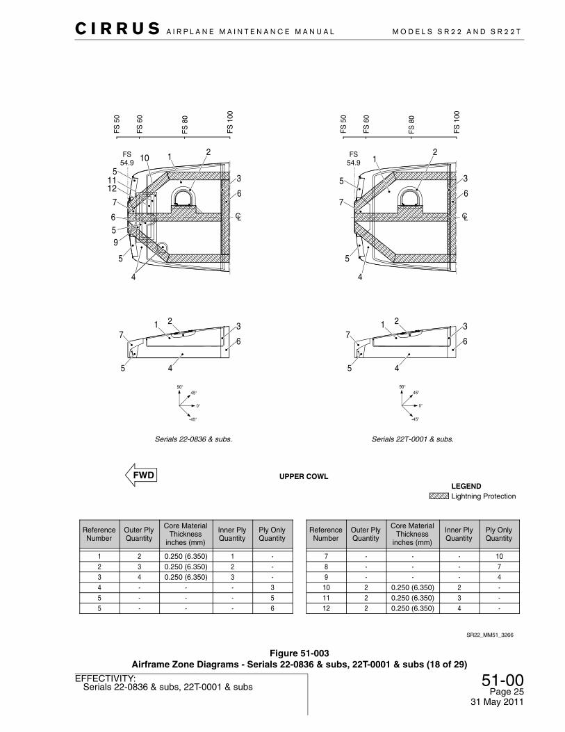
Figure 51-003Airframe Zone Diagrams - Serials 22-0836 & subs, 22T-0001 & subs (18 of 29)
SR22_MM51_3266
1
4
7
4
2
3
FS54.9
FS
50
FS
60
FS
80
FS
100
7
5
6
3
5
5
1
6
2
Serials 22T-0001 & subs.
45°
0°
-45°
90°
ReferenceNumber
Outer PlyQuantity
Core MaterialThickness
inches (mm)
Inner PlyQuantity
Ply OnlyQuantity
1234
234-
0.250 (6.350)0.250 (6.350)0.250 (6.350)
-
123-
---3
ReferenceNumber
Outer PlyQuantity
Core MaterialThickness
inches (mm)
Inner PlyQuantity
Ply OnlyQuantity
789
10
---2
---
0.250 (6.350)
---2
1074-
1
4
7
4
2
3
FS54.9
FS
50
FS
60
FS
80
FS
100
7
5
6
3
5
5
1
6
2
UPPER COWL
Serials 22-0836 & subs.
Lightning Protection LEGEND
45°
0°
-45°
90°
5 - - - 5 11 2 0.250 (6.350) 3 -5 - - - 6 12 2 0.250 (6.350) 4 -
659
1211
10
51-00Page 26
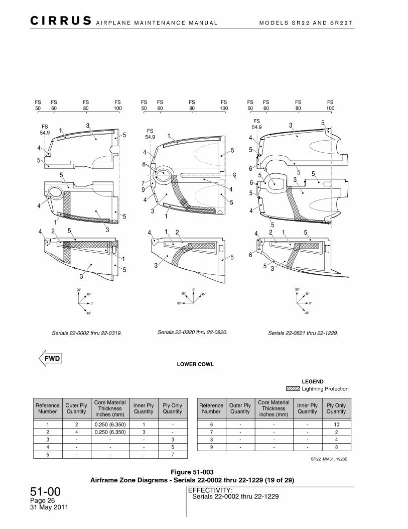
Serials 22-0002 thru 22-1229EFFECTIVITY:
C I R R U S A I R P L A N E M A I N T E N A N C E M A N U A L M O D E L S S R 2 2 A N D S R 2 2 T
Figure 51-003Airframe Zone Diagrams - Serials 22-0002 thru 22-1229 (19 of 29)
LC
SR22_MM51_1926B
2
5
3
4 5
5
1
1
1
3
47
8
4
4
9
53
4
5
6
5
FS100
536
5
45
5
124
6
5 3
FS54.9
4 5
ReferenceNumber
Outer PlyQuantity
Core MaterialThickness
inches (mm)
Inner PlyQuantity
Ply OnlyQuantity
1234
24--
0.250 (6.350)0.250 (6.350)
--
13--
--35
ReferenceNumber
Outer PlyQuantity
Core MaterialThickness
inches (mm)
Inner PlyQuantity
Ply OnlyQuantity
6789
----
----
----
10248
LOWER COWL
Serials 22-0821 thru 22-1229.
Lightning Protection LEGEND
5 - - - 7
Serials 22-0002 thru 22-0319.
FS50
FS60
FS80
FS100
FS50
FS60
FS80
FS80
FS60
FS50
FS100
FS54.9 FS
54.9
4
4
4
5
5
5
5
5
5
1
1
13
3
3
2
Serials 22-0320 thru 22-0820.
45°
0°
-45°
90°45°
0°
-45°
90°0°-45°
90°
45°
31 May 2011
C I R R U S A I R P L A N E M A I N T E N A N C E M A N U A L M O D E L S S R 2 2 A N D S R 2 2 T
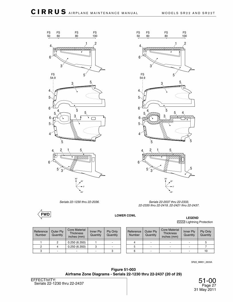
51-00Page 27Serials 22-1230 thru 22-2437
EFFECTIVITY:
31 May 2011
Figure 51-003Airframe Zone Diagrams - Serials 22-1230 thru 22-2437 (20 of 29)
43
55
5
6
5
4
5
4
5124
6
5 35
6 6
4 4
3 3
5 5
1 2 1 2
53
4
5
6 5
FS50
FS100
FS54.9
FS60
FS80
SR22_MM51_2633A
LOWER COWL
Serials 22-1230 thru 22-2036.
45°
0°
-45°
90°
FS50
FS100
FS54.9
FS60
FS80
Serials 22-2037 thru 22-2333,22-2335 thru 22-2419, 22-2421 thru 22-2437.
45°
0°
-45°
90°
ReferenceNumber
Outer PlyQuantity
Core MaterialThickness
inches (mm)
Inner PlyQuantity
Ply OnlyQuantity
123
424-
-0.250 (6.350)0.250 (6.350)
-
-13-
---3
5
ReferenceNumber
Outer PlyQuantity
Core MaterialThickness
inches (mm)
Inner PlyQuantity
Ply OnlyQuantity
6 - - - 10
Lightning Protection LEGEND
5 - - - 7
5
53
4
5
6
5
536
5
4
5
124
6
5 3
4 5
51-00Page 28
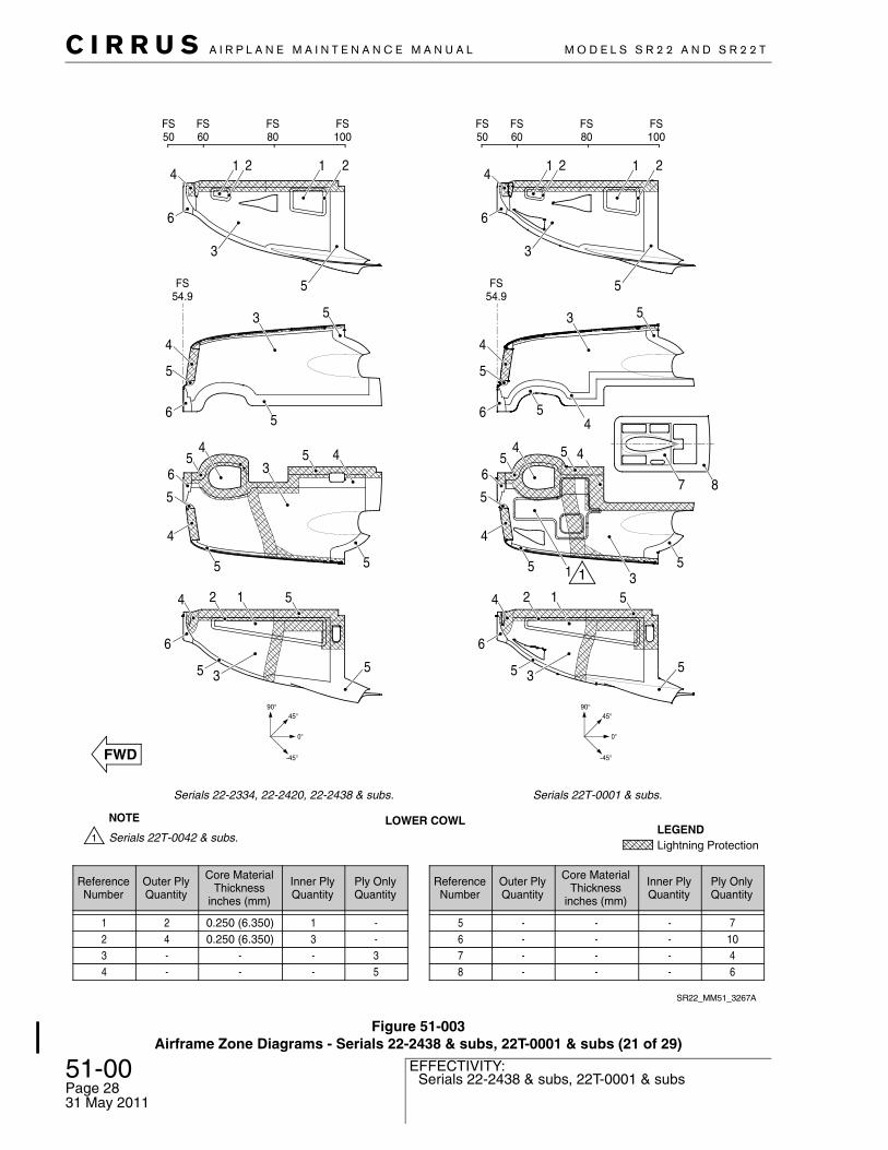
Serials 22-2438 & subs, 22T-0001 & subsEFFECTIVITY:
C I R R U S A I R P L A N E M A I N T E N A N C E M A N U A L M O D E L S S R 2 2 A N D S R 2 2 T
Figure 51-003Airframe Zone Diagrams - Serials 22-2438 & subs, 22T-0001 & subs (21 of 29)
4 - - - 5 8 - - - 6
87
1
FS100
FS50
FS60
FS80
4
43
55
5
6
5
4
5
4
5124
6
5 35
6
4
3
5
1 21 2
53
4
5
6 5
SR22_MM51_3267A
LOWER COWL
FS100
FS50
FS60
FS80
FS54.9
Serials 22-2334, 22-2420, 22-2438 & subs.
45°
0°
-45°
90°
ReferenceNumber
Outer PlyQuantity
Core MaterialThickness
inches (mm)
Inner PlyQuantity
Ply OnlyQuantity
123
524-
-0.250 (6.350)0.250 (6.350)
-
-13-
---3
7
ReferenceNumber
Outer PlyQuantity
Core MaterialThickness
inches (mm)
Inner PlyQuantity
Ply OnlyQuantity
7 - - - 4
Lightning Protection LEGEND
6 - - - 10
Serials 22T-0001 & subs.
45°
0°
-45°
90°
FS54.9
4
3
55
5
6
5
4
5
4
5124
6
5 35
6
4
3
5
1 21 2
53
4
5
6 5
NOTE
Serials 22T-0042 & subs.
31 May 2011
C I R R U S A I R P L A N E M A I N T E N A N C E M A N U A L M O D E L S S R 2 2 A N D S R 2 2 T
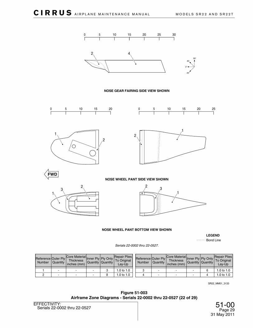
51-00Page 29Serials 22-0002 thru 22-0527
EFFECTIVITY:
31 May 2011
Figure 51-003Airframe Zone Diagrams - Serials 22-0002 thru 22-0527 (22 of 29)
0 5 10 15 20 25 30
2
82 1.0 to 1.0---63 1.0 to 1.0---31 1.0 to 1.0---
Ply OnlyQuantity
Inner PlyQuantity
Core MaterialThickness
inches (mm)
Outer PlyQuantity
ReferenceNumber
Repair PliesTo Original
Lay-Up
44 1.0 to 1.0---
Ply OnlyQuantity
Inner PlyQuantity
Core MaterialThickness
inches (mm)
Outer PlyQuantity
ReferenceNumber
Repair PliesTo Original
Lay-Up
45°
0°
-45°
90°
NOSE WHEEL PANT BOTTOM VIEW SHOWN
0 5 10 15 20 0 5 10 15 20 25
SR22_MM51_3133
Bond LineLEGEND
Serials 22-0002 thru 22-0527.
NOSE WHEEL PANT SIDE VIEW SHOWN
NOSE GEAR FAIRING SIDE VIEW SHOWN
1
1 1
12
2
23 3
2
4

51-00Page 30
Serials 22-0528 thru 22-2333, 22-2335 thru 22-2419, 22-2421 thru 22-2437
EFFECTIVITY:
C I R R U S A I R P L A N E M A I N T E N A N C E M A N U A L M O D E L S S R 2 2 A N D S R 2 2 T
Figure 51-004Airframe Zone Diagrams - Serials 22-0528 thru 22-2333, 22-2335 thru 22-2419, 22-2421 thru 22-2437 (23 of 29)
NOSE WHEEL PANT SIDE VIEW SHOWN
34
222
2 2
1
1
1 3
4
1
0 5 0 510 10 15 20 25 30 35
0 5 10 15 20 25 30
NOSE WHEEL PANT BOTTOM VIEW SHOWN
SR22_MM51_3134
Bond LineLEGEND
52 1.0 to 1.0---23 1.0 to 1.0---31 1.0 to 1.0---
Ply OnlyQuantity
Inner PlyQuantity
Core MaterialThickness
inches (mm)
Outer PlyQuantity
ReferenceNumber
Repair PliesTo Original
Lay-Up
104 1.0 to 1.0---
Ply OnlyQuantity
Inner PlyQuantity
Core MaterialThickness
inches (mm)
Outer PlyQuantity
ReferenceNumber
Repair PliesTo Original
Lay-Up
Serials 22-0528 thru 22-2333, 22-2335 thru 22-2419, 22-2421 thru 22-2437.
NOSE GEAR FAIRING SIDE VIEW SHOWN
45°
0°
-45°
90°
45°
0°
-45°
90°
31 May 2011
C I R R U S A I R P L A N E M A I N T E N A N C E M A N U A L M O D E L S S R 2 2 A N D S R 2 2 T
51-00Page 31Serials 22-2334, 22-2420, 22-2438 & subs
EFFECTIVITY:
Figure 51-004Airframe Zone Diagrams - Serials 22-2334, 22-2420, 22-2438 & subs (24 of 29)
0 5 0 510 10 15 20 25 30 35
0 5 10 15 20 25 30
0°
-45°
90°
45°
45°
0°
-45°
90°
NOSE WHEEL PANT BOTTOM VIEW SHOWN
SR22_MM51_3135A
Bond LineLEGEND
43 1.0 to 1.0---22 1.0 to 1.0---
104 1.0 to 1.0---31 1.0 to 1.0---
Ply OnlyQuantity
Inner PlyQuantity
Core MaterialThickness
inches (mm)
Outer PlyQuantity
ReferenceNumber
Repair PliesTo Original
Lay-Up
55 1.0 to 1.0---
Ply OnlyQuantity
Inner PlyQuantity
Core MaterialThickness
inches (mm)
Outer PlyQuantity
ReferenceNumber
Repair PliesTo Original
Lay-Up
Serials 22-2334, 22-2420, 22-2438 & subs.
NOSE WHEEL PANT SIDE VIEW SHOWN
NOSE GEAR FAIRING SIDE VIEW SHOWN
1
23
32
245
54
2
1
31 May 2011

51-00Page 32
Serials 22T-0001 & subsEFFECTIVITY:
C I R R U S A I R P L A N E M A I N T E N A N C E M A N U A L M O D E L S S R 2 2 A N D S R 2 2 T
31 May 2011
Figure 51-005Airframe Zone Diagrams - Serials 22T-0001 & subs (25 of 29)
35 40
0 5 0 510 10 15 20 25 30 35
0 5 10 15 20 25 30
0°
-45°
90°
45°
45°
0°
-45°
90°
NOSE WHEEL PANT BOTTOM VIEW SHOWN
SR22_MM51_3342
Bond LineLEGEND
43 1.0 to 1.0---22 1.0 to 1.0---
104 1.0 to 1.0---31 1.0 to 1.0---
Ply OnlyQuantity
Inner PlyQuantity
Core MaterialThickness
inches (mm)
Outer PlyQuantity
ReferenceNumber
Repair PliesTo Original
Lay-Up
55 1.0 to 1.0---
Ply OnlyQuantity
Inner PlyQuantity
Core MaterialThickness
inches (mm)
Outer PlyQuantity
ReferenceNumber
Repair PliesTo Original
Lay-Up
Serials 22T-0001 & subs.
NOSE WHEEL PANT SIDE VIEW SHOWN
NOSE GEAR FAIRING SIDE VIEW SHOWN
1
23
32
245
54
2
1
C I R R U S A I R P L A N E M A I N T E N A N C E M A N U A L M O D E L S S R 2 2 A N D S R 2 2 T
51-00Page 33Serials 22-0002 thru 22-2333, 22-2335 thru 22-2419,
22-2421 thru 22-2437
EFFECTIVITY:
Figure 51-006Airframe Zone Diagrams - Serials 22-0002 thru 22-2333, 22-2335 thru 22-2419, 22-2421 thru 22-2437 (26 of 29)
1
0 5 10 15 20 25 30 35 40 0 5 10 15
0 5 10 0 5 10 15 20
45°
0°
-45°
90°
45°
0°
-45°
90°
MAIN WHEEL PANT LEFT SIDE SHOWNMAIN WHEEL PANT RIGHT SIDE OPPOSITE
Bond LineLEGEND
22 1.0 to 1.0---53 1.0 to 1.0---31 1.0 to 1.0---
Ply OnlyQuantity
Inner PlyQuantity
Core MaterialThickness
inches (mm)
Outer PlyQuantity
ReferenceNumber
Repair PliesTo Original
Lay-Up
84 1.0 to 1.0---
Ply OnlyQuantity
Inner PlyQuantity
Core MaterialThickness
inches (mm)
Outer PlyQuantity
ReferenceNumber
Repair PliesTo Original
Lay-Up
Serials 22-0002 thru 22-2333, 22-2335 thru 22-2419, 22-2421 thru 22-2437.
MAIN GEAR UPPER STRUT FAIRING LEFT SIDE SHOWNMAIN GEAR UPPER STRUT FAIRING RIGHT SIDE OPPOSITE
45°0°
-45°
90°
SR22_MM51_3136
MAIN GEAR STRUT FAIRING LEFT SIDE SHOWNMAIN GEAR STRUT FAIRING RIGHT SIDE OPPOSITE
1
12
2
2
21
1
4
3
3
3
3
3 1
31 May 2011
51-00Page 34
Serials 22-2334, 22-2420, 22-2438 & subs, 22T-0001 & subs
EFFECTIVITY:
C I R R U S A I R P L A N E M A I N T E N A N C E M A N U A L M O D E L S S R 2 2 A N D S R 2 2 T
31 May 2011
Figure 51-006Airframe Zone Diagrams - Serials 22-2334, 22-2420, 22-2438 & subs, 22T-0001 & subs (27 of 29)
83 1.0 to 1.0---
0 5 10 15 20
0 5 10 15 20 25 30 35 40 0 5 10 15
MAIN WHEEL PANT LEFT SIDE SHOWNMAIN WHEEL PANT RIGHT SIDE OPPOSITE
Bond LineLEGEND
22 1.0 to 1.0---54 1.0 to 1.0---31 1.0 to 1.0---
Ply OnlyQuantity
Inner PlyQuantity
Core MaterialThickness
inches (mm)
Outer PlyQuantity
ReferenceNumber
Repair PliesTo Original
Lay-Up
45 1.0 to 1.0---
Ply OnlyQuantity
Inner PlyQuantity
Core MaterialThickness
inches (mm)
Outer PlyQuantity
ReferenceNumber
Repair PliesTo Original
Lay-Up
Serials 22-2334, 22-2420, 22-2438 & subs, 22T-0001 & subs.
SR22_MM51_3137
MAIN GEAR UPPER STRUT FAIRING LEFT SIDE SHOWNMAIN GEAR UPPER STRUT FAIRING RIGHT SIDE OPPOSITE
1
4
2
1 4
52
31
12
21
C I R R U S A I R P L A N E M A I N T E N A N C E M A N U A L M O D E L S S R 2 2 A N D S R 2 2 T
51-00Page 35Serials 22-0002 thru 22-0820
EFFECTIVITY:
Figure 51-006Airframe Zone Diagrams - Serials 22-0002 thru 22-0820 (28 of 29)
SR22_MM51_2127
ReferenceNumber
Outer PlyQuantity
Core MaterialThickness
inches (mm)
Inner PlyQuantity
Ply OnlyQuantity
123
233
0.250 (6.350)0.250 (6.350)0.250 (6.350)
423
---
ReferenceNumber
Outer PlyQuantity
Core MaterialThickness
inches (mm)
Inner PlyQuantity
Ply OnlyQuantity
91011
---
---
---
156
13
CABIN DOOR OUTER SKIN
WL 134.0
WL 130.0
WL 120.0
WL 110.0
WL 100.0
WL 96.0
FS120
FS140
FS160
FS174
13
11
9
10
5
7
10
12
1 2 53
Serials 22-0458 thru 22-0820 only.
NOTE
No Repair AreaLEGEND
4 3 0.250 (6.350) 6 -12 - - - 85 3 0.250 (6.350) 4 -13 - - - 96 2 0.250 (6.350) 2 -14 2 0.250 (6.350) 3 -7 - - - 4
8 - - - 7
4
26
7
8
9
1110
11
9
9
8
146
Serials 22-0002 thru 22-0820.
90°45°
0°
-45°
31 May 2011

51-00Page 36
Serials 22-0821 & subs, 22T-0001 & subsEFFECTIVITY:
C I R R U S A I R P L A N E M A I N T E N A N C E M A N U A L M O D E L S S R 2 2 A N D S R 2 2 T
31 May 2011
Figure 51-006Airframe Zone Diagrams - Serials 22-0821 & subs, 22T-0001 & subs (29 of 29)
SR22_MM51_2134
1
ReferenceNumber
Outer PlyQuantity
Core MaterialThickness
inches (mm)
Inner PlyQuantity
Ply OnlyQuantity
1234
--55
--
0.77 (19.56)1.15 (29.21)
--33
68--
ReferenceNumber
Outer PlyQuantity
Core MaterialThickness
inches (mm)
Inner PlyQuantity
Ply OnlyQuantity
789
10
3333
0.77 (19.56)1.15 (29.21)1.95 (49.53)0.25 (6.35)
3335
----
CABIN DOOR
5 5 0.25 (6.35) 3 -
45°
0°
-45°
90°
FS124
FS140
FS160
FS174
WL 134.0
WL 130.0
WL 120.0
WL 110.0
WL 100.0
WL 96.0
11 3 1.15 (29.21) 4 -6 3 0.25 (6.35) 3 -
1
2
34 5
68
7
6
11
1110 9
8
7
8
7
54
32
6
Serials 22-0821 & subs,22T-0001 & subs.

C I R R U S A I R P L A N E M A I N T E N A N C E M A N U A L M O D E L S S R 2 2 A N D S R 2 2 T
51-00Page 37All
EFFECTIVITY:
F. Definition of Terms
A
Abrasion Wearing away a material surface by friction. Particles become detached by a com-bined cutting, shearing and tearing action.
Accelerator A material which is added to a mixture of resin and catalyst to speed up the curing reaction.
Adhesion The state in which two surfaces are held together by interfacial forces consisting of chemical, mechanical forces or both.
Adhesive A substance capable of holding materials together by adhesion.
Advanced Composite
Composite materials in which relatively high strength and/or stiffness fibers are embedded in homogeneous matrix materials.
Air Bubble Void Air entrapment within and between the plies of the laminate.
Ambient Tempera-ture
Environment temperature surrounding the object under consideration. Usually refers to room temperature.
Amine Blush A wax-like film on cured epoxy surfaces. It is a by-product of the epoxy curing pro-cess and may begin to form during the initial cure phase.
B
Backing Plate A plate used behind a hole in the structure when making a composite repair. The backing plate is considered a tool and is not considered to add any strength to the repair.
Bag Side The side of a vacuum bagged part opposite the tool surface.
Bleeder Cloth A material, usually treated or untreated fiberglass cloth, used in the manufacture of composite parts to absorb excess resin.The bleeder cloth is separated from the part after cure and is not part of the composite.
Bond Gap The attachment of an interface between an adhesive and an adherend.
Bond Joint The structure between two parts, that connects the two parts together. A standard bond joint includes one layer of adhesive joining the two parts. A shimmed bond joint includes two layers of adhesive separated by a solid composite shim.
Bond Length The length of area overlapping bond (usually much longer than the width).
Bond Void An area in a bondline void of adhesive.
Bond Width The overlapping width of the components being joined.
Bonding See “Secondary Bonding”.
Bondline The path of the bond. The bondline is not necessarily straight, and may fork into dif-ferent directions when two complexly shaped parts are bonded together.
Bondline Thickness The thickness of the adhesive between two bonded parts. The bond thickness may be larger than the bond gap due to the hydraulic forces of the adhesive holding the parts farther apart. Bondline thickness is synonymous with bond thickness and adhesive thickness.
31 May 2011

51-00Page 38
AllEFFECTIVITY:
C I R R U S A I R P L A N E M A I N T E N A N C E M A N U A L M O D E L S S R 2 2 A N D S R 2 2 T
31 May 2011
Bondline Thickness, Total
The sum of the thicknesses of the bondlines in a shimmed bond joint. A shim installed in a bond joint will result in two bondlines of thickness, X and Y. The total bondline thickness is the sum of X and Y. Total bondline thickness is synonymous with total adhesive thickness.
Breather Cloth A loosely woven material such as fiberglass fabric which is placed between the composite layup and the vacuum bag to provide a continuous vacuum path. Breathers are generally separated from resin by a barrier such as a layer of FEP (Fluorinated Ethylene Propylene) film.
Bridging A condition where one or more plies in a composite layup span a radius, step or chamfer without full contact resulting in a local void or a zone of un-reinforced resin.
Butt Splice A joint formed by fitting segments end-to-end or side-by-side with no overlap required. Commonly used where thickness is critical and/or where reinforcement continuity is not required.
C
Cap The flange of a spar, typically at right angles to the web. Usually used as the faying surface for a secondary bond to other structure, such as a wing skin.
Co-bonding The act of curing a composite laminate and simultaneously bonding it to another prepared surface.
Co-Curing The act of curing and bonding multiple composite details in the same composite assembly during the same cure cycle.
Composite Material A complex material in which two or more distinct structurally complementary sub-stances are used together to produce structural or functional properties not present in the individual components. No chemical mixing occurs in the individual compo-nents. Properties may be highly directional, being dependant on the distribution and orientation of substances within the material.
Core The central member, usually foam or honeycomb, of a sandwich construction to which the laminate faces of the sandwich are attached or bonded.
Core Crush A permanent collapse, distortion, or compression of the core in a core sandwich composite.
Core Depression A localized indentation or gouge in the core of a core sandwich composite.
Core Separation A partial or complete breaking of core node bonds which are found in honeycomb core material.
Core Splicing The joining of two core segments by bonding, pegging or crushing one segment into another.
Cosmetic Repair A score or minor abrasion through the resin coat.
Crack (Composite) 1) A break, fracture, or split of a part, resulting in local resin or matrix damage and possible fiber tearing. 2) A fracture in a previously sound bond, characterized by separation of material. See also “Disbond”.
Crazing Minute cracks which appear on the surface of a laminate at stress concentrations or resin rich areas.
Cross Ply Filamentary laminate and sandwich face sheets which are not uniaxial - oriented at 90º with respect to uniaxial direction.
C I R R U S A I R P L A N E M A I N T E N A N C E M A N U A L M O D E L S S R 2 2 A N D S R 2 2 T
51-00Page 39All
EFFECTIVITY:
Cure To permanently change the properties of a resin system by controlled chemical reaction. This may require applied heat and pressure over a length of time.
Cure Cycle The variation of temperature and pressure over a period of time used to cure a composite detail.
D
Deformation Any change of form or shape produced in a body by a stress or force.
Degradation A deleterious change in the chemical structure of a plastic.
Delamination Separation of the core and laminate face sheets or separation between plies of a laminate.
Disbond An area within a bonded interface between two parts in which an adhesion failure or separation has occurred.
Discoloration Local areas of lighter, darker, or otherwise differently appearing laminate. Changes in opacity can appear as discoloration also.
Doubler Ply A local reinforcement ply in laminate structure.
Drape Ability of cloth to conform to irregular shape.
Dry Area(s) Area(s) of incomplete surface film where the reinforcement has not been suffi-ciently wetted with resin. Also called "surface porosity". This condition may not be limited to the surface of a part.
E
Elevated Temperature
Material temperature of 180º F when loaded into a test fixture.
EMM Expanded Metal Mesh - A metallic mesh applied near one surface of the laminate to direct current caused by lightning strike in flight.
Epoxy A flexible thermosetting resin made by polymerization of an epoxide.
F
Faying Surface The surface of adherends in contact with the adhesive and joined, or about to be joined.
Fiber Damage Local tearing or breakage of several individual filaments of reinforcing fibers within a yarn or roving group.
Fiber Direction The orientation or alignment of the longitudinal axis of the fiber with respect to a stated reference axis.
Fiberglass Fibrous form of glass used in making filaments, woven fabric, yarns, etc.
Fiberglass Cloth Woven fiberglass material.
Filament A single continuous homogeneous strand of material (fiber), characterized by extreme length, usually limited by spool weight.
Fill Yarn oriented at right angles to the warp yarns in a woven fabric. Direction perpen-dicular to the lengthwise (continuous) dimension in a woven fabric.
31 May 2011
51-00Page 40
AllEFFECTIVITY:
C I R R U S A I R P L A N E M A I N T E N A N C E M A N U A L M O D E L S S R 2 2 A N D S R 2 2 T
31 May 2011
Filler A relatively inert substance added to a material to alter its physical, mechanical, thermal, electrical, and other properties. Fillers are also used to lower cost and density.
Finish A treatment applied to the fibers to improve bonding between the fiber surface and matrix resin.
G
Gelling Time The time taken for a resin to set to a non-fluid gel state.
Glass Cloth A type of fabric made from fine spun glass filaments which are woven into a strong, tough fabric. These fabrics are used to construct, reinforce, and repair composite structures.
Glass Fiber Filaments of fine spun glass.
Glass/Resin Ratio Proportions of glass reinforcement and resin by volume or more usually by weight. Used as an indicator of quality and physical properties.
H
Hand Lay-Up An open mold process in which resin and fiber reinforcements are applied to the mold and the composite is built up by hand.
Handling Life The period of time in which the material still maintains physical and chemical prop-erties within the specified limits.
Hardener See “Curing Agent”.
Hybrid A composite comprised of two or more composite material systems, such as graph-ite/epoxy with glass/epoxy.
I
Impact Damage Separation of material through the thickness or visible cracks on surface caused by impact with another object.
Inclusion 1) Unintentional placement in a composite layup of foreign material which are visi-ble to the unaided eye, such as particles, films, etc.2) Particles or pieces of substance in a bond joint that are foreign to its composi-tion.
J
Joint The location at which two adherends are held together with a layer of adhesive. The general area of contact for a bonded joint.
K
L
Lamina Single layer of unidirectional or woven fibers embedded in a resin matrix.
Laminate Product made by bonding together two or more layers (laminae) of material or materials. Usually the matrix acts as the bonding material with the curing process normally effected through the use of a catalyst, pressure and/or heat (although not necessarily in combination).
Laminate Orientation The configuration of a composite laminate with regard to the direction of each ply relative to a specified direction, and the exact sequence of individual plies.

C I R R U S A I R P L A N E M A I N T E N A N C E M A N U A L M O D E L S S R 2 2 A N D S R 2 2 T
51-00Page 41All
EFFECTIVITY:
Lamination The process of preparing a laminate.
Lap A joint formed by the overlap of a ply or laminate over another. Usually character-ized by a “lap distance” or “ply drop off distance”. The lap length is the distance available for the overlapping repair or reinforcing ply to develop strength.
Lap Joint A joint made by placing one adherend partly over another and bonding the over-lapped portions together.
Lay-Up 1) A fabrication process where successive layers of material are placed on a tool to fabricate a laminate or core sandwich. 2) The uncured part itself. 3) The composi-tion of a laminate expressed as the percentage of fibers in each direction. 4) The stacking sequence.
M
Matrix The homogeneous material in which the fibers of a composite are embedded.
Microcracking Microscopic cracks in a matrix.
N
O
Overlap Splice A joint formed by overlapping one segment with the next. Used where reinforce-ment continuity is required. May also be formed by a third piece that overlaps both segments to be joined. Implied by the term “splice” in reference to the lay-up pro-cess.
P
Peel Ply A special ply used as the outer layer which is peeled off after cure to provide a smooth contaminate free repair surface.
Pin Holes Small holes in a cured part surface which are unfilled by matrix material.
Pitting Small crater in the surfaces of a part, with its width approximately of the same order of magnitude as its depth. See also "Pin Holes".
Plies Layers of material (glass cloth or glass fiber) which are laminated together.
Ply A single layer of tape, fabric or filaments.
Ply Wrinkle A condition where one or more plies in a cured composite part are ridged, depressed or folded.
Polymer An organic material composed of long molecular chains consisting of repeating chemical units.
Porosity A cluster of small voids within an otherwise solid material, usually expressed as a volumetric percentage. The presence of numerous visible pin holes, pits, or small voids. Can be localized or wide spread.
Pot Life The length of time that a catalyzed thermosetting resin system retains a viscosity low enough to be used in processing.
31 May 2011
51-00Page 42
AllEFFECTIVITY:
C I R R U S A I R P L A N E M A I N T E N A N C E M A N U A L M O D E L S S R 2 2 A N D S R 2 2 T
31 May 2011
Q
R
Release Film An impermeable layer of film that does not bond to the resin being cured. Both sides of the release film are adhesive free.
Release Tape A plastic film with adhesive backing on one side. Release tape is used during back-ing plate manufacture to allow the backing plate to release from the lay-up surface without damage.
Resin The matrix material in fiber/resin composites, i.e. epoxy resin.
Resin Content The amount of resin matrix in a composite. The resin content may be expressed as a weight percentage or as a volume percentage.
Resin Infusion A laminate manufacturing process where by resin is drawn through the reinforcing fibres using vacuum, most usually under a flexible vacuum bag.
Resin Pocket An apparent accumulation of excess resin in a small, localized area.
Resin Richness An area of excess resin, usually occurs at radii, steps or transition points on a com-posite. A local area of the laminate that exceeds nominal resin content. It is usually characterized by excessive laminate thickness and sometimes appears to have some discoloration.
Resin Starved An area of resin deficiency resulting in uncovered fibers, surface porosity or pin holes. See also “Dry Area(s)”.
Retarder A material which slows down the rate of cure of a resin (opposite to accelerator).
S
Sandwich Construction
A bonded structure in which a core of material such as rigid foam is bonded between two laminate face sheets of metal or fiberglass cloth. Sandwich con-structed materials are used where high strength and light weight are required.
Scarf Joint A joint made by cutting away angular segments of a part and then either bonding a second part with similar angular cuts or wet laying material with staggered widths.
Scratch Shallow mark, groove, or channel on the laminate surface. Features are not consid-ered scratches if intentionally molded into the part (e.g. scribe lines).
Secondary Bond The joining together, by the process of adhesive bonding, of two or more compo-nents, during which the only chemical or thermal reaction occurring is the curing of the adhesive itself. The term secondary implies that this is a secondary process, and occurs after the laminates have been cured. The term secondary DOES NOT imply that the joint is non-structural or unimportant. The most common application of the secondary bond are primary structural joints.
Selvage Edge The edge on either side of a woven fabric, finished so as to prevent raveling.
Shelf Life or Storage Life
Length of time a material can be stored under specified environmental conditions and continue to meet applicable specification requirements and/or remain suitable for its intended function.
Stiffener Bonded frames to support a panel and reduce panel dimensions
Storage Life The time in storage over which the material maintains its mechanical properties as defined by the specification.

C I R R U S A I R P L A N E M A I N T E N A N C E M A N U A L M O D E L S S R 2 2 A N D S R 2 2 T
51-00Page 43All
EFFECTIVITY:
Symmetrical Laminate
A composite laminate in which the ply orientation is symmetrical about the laminate mid-plane, i.e. (0,+45,-45,-45,+45,0).
T
Template A pattern made of any suitable material to permit the layout of parts with a mini-mum expenditure of time and effort.
Tool Side The surface of the part which is in contact with the tool during fabrication. See also “Inner Mold Line” and “Outer Mold Line”.
Tow A bundle of fibers. Yarns are made from one or more “tows”.
U
Unidirectional Cloth A cloth with high strength in one direction (either weft or warp), as compared with the other.
V
Vacuum Bag A flexible encapsulating membrane over a composite layup which is used for com-pacting the composite under vacuum pressure prior to cure and providing pressure during cure.
Void 1) An empty space within the resin-fiber system. Voids are due to local resin starva-tion and ply bridging. 2) Gaseous pockets that have been trapped within the adhe-sive and between the adherends.
W
Whitening The separation of fabric from resin. White color occurs due to the way light refracts in the composite laminate. Indicates the onset of fatigue failure. The size of the ini-tial failure spots corresponds to the weave crimp dimensions.
Warp Lengthwise direction in woven fabric.
Water Absorption The increase in weight of a test specimen of defined dimensions after immersion in water for a specified time at a specified temperature.
Weave Interlacing of a series of yarns in 2 or more directions.
Web A sheet or plate section connecting relatively thicker sections (flanges, caps, etc.) of a structural element.
Weft The transverse threads or fibres in a woven fabric. Those fibres running perpendic-ular to the warp.
Wet Lay-up A method of making a reinforced product by applying the resin system as a liquid when the reinforcement is put in place.
Wet-Lay See "Wet Lay-up".
Woven Roving The weaving together of rovings which are non-woven, non-twisted strands of glass filaments laid together in ‘parallel’.
Wrinkle An imperfection in the laminate in which one or more plies has the appearance of a wave, wrinkle, or crease.
31 May 2011
51-00Page 44
AllEFFECTIVITY:
C I R R U S A I R P L A N E M A I N T E N A N C E M A N U A L M O D E L S S R 2 2 A N D S R 2 2 T
31 May 2011
X
Y
Z