Embed Size (px)
Citation preview

SR Spectroscopieson Solids, Surfaces, and Interfaces
Giancarlo Panaccione
Lesson IV:From the source to the sample:
The Beamline

1) Handbook on Synchrotron Radiation, ed., E.-E. Koch, North-Holland Publishing Company; (North Holland, Amsterdam, 1983)
2) www.lightsource.org
3) The future of Synchrotron Radiation, Y. Petroff, Journ. El. Spec. and Rel. Phenomena,156-158 (2007) 10.
4) J. Als-Nielsen and D. McMorrow, Elements of Modern X-ray Physics(Wiley, New York, 2001).
5) X-Ray Data BookletSection 2.1 Kwang-Je Kim Characteristics of Synchrotron Radiation
Useful References

S
S
e-
Circular Polarization
hν
S
S
e- hν
Linear Polarization (Vertical)
Phase Shift 0 = linear horizPhase Shift ½ λu = linear vertPhase Shift ¼ λu= circular
APE beamline
Light source ---- Undulator
e- hν
Linear Polarization (Horizontal)
APPLE II-type undulatorsAPE beamline undulators: Characteristics
Switch Time < 10 secNO ELLIPTICAL POL
NO POL ANGLE

New devices: Figure 8 undulator

APE beamline undulators: Zig-zag configuration
Two undulators are placed in the same straight section.2 mrad zig-zag angle. Closed loop.Separation of beams 40 mm a 20 metersNo pinholes, high thermal load
24 meters from the undulatorFirst mirror
APE beamline

The Shapal® target Gap HE=40 mmGap LE=80 mm
Gap HE=40 mmGap LE=60 mm
Gap HE=40 mmGap LE=30 mm
(Horizontally polarized light)
Measured Expected• HE beam @ Gap 40 mm 15 mm 12 mm• LE beam @ Gap 80 mm 15 mm 12 mm• LE beam @ Gap 60 mm 22 mm 25 mm
APE beamline undulators: Reality

• Low Energy Polarization: Horizontal → Vertical• High Energy Polarization: Vertical
• 2 mRad angular divergence between beams → Distance between the beams = 34 mm
APE beamline undulators: Reality
(From Horizontal to Vertical polarized light)

120.63100.4880.7817125
1230.51930.43620.773660
ε1 (eV)B0 (T)ε1 (eV) B0 (T)ε1 (eV)B0 (T)
Vertical Polarization
Circular PolarizationHorizontalPolarization
Npperiod (mm)
MeasuredEU 6.0 HEEU 12.5 LE
130.60100.4880.7717125
1230.51940.42590.783660
ε1 (eV)B0 (T)ε1 (eV) B0 (T)ε1 (eV)B0 (T)
Vertical Polarization
Circular PolarizationHorizontalPolarization
Npperiod (mm)
DesignR. Walker, B. Diviacco(ELETTRA)
APE beamline undulators: Parameters at minimum gap

APE beamline EU 12.5: Quasi-periodic

Spectra computed from ideal (black) and measured (red) field
in linear and circular polarization
APE beamline EU 12.5: Quasi-periodic

2x10⁶
1
0
Inte
nsity
(a.
u.)
80604020Kinetic energy (eV)
2.2 X 10⁶ counts
1.2 X 10⁴ counts
1.0
0.5
0Inte
nsity
(a.
u.)
20.7520.70Kinetic energy (eV)
FE width 45 meVT~120 K
Ag(100) Valence band extended spectra at hν=25 eVthe kinetic energy region spans
the second and third order energy range, showing 1% overall contribution.
APE beamline EU 12.5: Quasi-periodicity and ARPESSuppression of higher order intensity

APE - EU 12.5: quasi-harmonicsafter monochromator: data vs. calculation

Entrance Slits or Slitless?The importance of the source stability!
From (www.coe.berkeley.edu/AST/sxreuv)

78°
84°
1,9 m
0,5 m
2,9 m
M1
RM2a
M3
24 m
Plane Grating 700l/mm 10-25eV 150° 1200l/mm 20-45eV 150° 160l/mm 35-80eV 160°
Toroidal Mirror R = 13,46 m r = 0,477 m
Spherical Mirror R =115,3 m
R { +0° +15°
160°
150°
0,256 m
M2b
M2a R=61,65 m M2b R=104,6 m
4 m
0,730 m
5,9 m
0,25
m
8,05 m
APE – Low Energy Beamline – Optical layout

Side view
Top view
Pin
hole
Pref
ocus
ing
Entra
nce
slit
Mon
ochr
omat
or
Exit
slit
Def
lect
ion
mirr
or
Ver
tical
focu
sing
Hor
izon
tal f
ocus
ing
VFM
HFM
Prefocusing section: Adapt the source to the monochromator requirementsAdsorb the unwanted power radiation
Monochromator:Select the proper photon energy
Refocusing section: Adapt the spot shape at the necessity of the experiment
Courtesy , D. Cocco, ELETTRA, Trieste
Nanospectroscopy – X-ray PEEM

Pre-focusing MirrorSpherical Gratings: different for HE and LE
Same principle
Exit Slit
Re-focusing MirrorToroidal
Sample
Photon Source(Undulator)
Mirror
Plane Grating Monochromator (PGM) +Spherical Mirrors
APE beamline: Layouthttp://www.elettra.trieste.it/experiments/beamlines/
No entrance SlitsNo pinhole!

Schematic of the two entrance mirrors of the APE beamline.
Concrete block and granite support are used to guarantee mechanical stability
First Mirror – Power load and stability
Maximum slope error : 1 µrad RMS for both transverse and longitudinal profiles.
Maximum roughness : 3 Å RMS

280
Silicon blankCopper coolingblock
Mirrors are cooled to 40 K with He gas systemR. Dausman (Cryomech inc.)
Mirror temperature <100 K under power load (average 220 W on each mirror)
First Mirror – Power load and stability

360
320
280
240
200
160
120
8040
0
Verti
cal S
cale
(µm
)
450400350300250200150100500
Horizontal Scale (µm)
200
100
0
-30x10 -6
-25
-20
-15
-10
-5
0
5
10
15
20
25
30
effic
ienc
y (%
)
280260240220200180160140120100806040200
Photon ene rgy (eV)
-10x10-6
-5
0
5
10
slope
(rad
)
0 10080604020x (mm)
Slope error of the internally cooled mirror
Slope error bendable mirror
Courtesy , D. Cocco, ELETTRA, Trieste
VUV and Soft X-ray mirrors: quality tests

VUV and Soft X-ray Monochromator: gratings
X-ray diffraction grating: Structure having a surface capable of reflecting x-rays, said surface being grooved so that in cross-section the profile alternates regularly between geometrically similar lines, in which the height of the alternation varies significantly over the area of the surface. The grating may be plane or curved; the variation in height may occur as a single step, a plurality of steps or may be continuous; the variation may occur either transverse to or parallel to the grooving.
mλ = 2d (sin α - sin β)
m = order of diffractiond = distance between grooveα, β = angles incidence,reflection

VUV and Soft X-ray Monochromator: gratings
N = order of diffractionDifferent reflection angleDefine dispersive planeDefine where slits are
Blaze is used to improve one reflection only and
depress the others

Blazed Diffraction GratingBy tilting the facets of the grating so the desired diffraction ordercoincides with the specular reflection from the facets, the grating efficiency can be increased.
Specular means angle of incidence equals angle
of reflection.Input beam
Efficient diffraction
Inefficient diffraction
Even though both diffracted beams satisfy the grating equation, one is more intense than the other.

d
How accurate is a diffraction-grating spectrometer (a grating followed by a lens)?Recall the grating dispersion: cos( )
m
m
d md aθλ θ
= 1 [ cos( )/ 2]m
fwd
λπ θ
=
2w1
f
Two similar colors illuminate the grating.
f
cos( )mm
mf fa
δθ δλθ
=
Two nearby wavelengths will be separated by:
12 2cos( ) [ cos( ) / 2]m m
m f fwa d
λδλθ π θ
= =Setting this distance equal to the focused-spot diameter:
4 am dλδλπ
= 4m Nλδλπ
= where N = # grating lines illuminated = d / a
dcos(θ
m )
or
cos( )mm
ma
δθ δλθ
=
Diffraction-grating/spectrometer resolution:simple formulas

2w0
2w1
ff
4m Nλδλπ
=
λ ≈ 600 nm m = 1 N = (50 mm) x (2400 lines/mm) = 120,000 lines
0.007 nmδλ⇒ ≈
For simple order-of-magnitude estimates, 4 / p ≈ 1:
1mN
δλλ
≈And the resolution depends only on the
wavelength, order,
and how many lines are illuminated!
2” grating with 2400 lines/mm
Resolution:
Diffraction-grating/spectrometer resolution:simple formulas

VUV and Soft X-ray gratings: dimensions
Kohzu monochromator installed at the Advanced Photon Source (APS).
(Credit: Argonne National Laboratory)

Diffraction EfficiencyMany optical systems demand high optical throughput. For a holographic grating, 1st order diffraction efficiencies better than 95% are obtainable in either transmission or reflection. However, in order to achieve these high efficiencies in manufacturing, proper modeling tools as well as intuition and experience are required.
Stray Light Holographic gratings inherently offer lower stray light and structured noise than ruled gratings. However, less experienced holographers may not perform the steps necessary to reduce stray light for the most demanding systems.
DurabilityChoose gratings made of materials resistant to high temperatures and solvents. Replica gratings produced from thermal epoxies typically have low Tg (<80°C) and deform when exposed to harsh solvents. If durability is important, be sure to use cold formed gratings.
Coatings When coating a grating with enhanced aluminum, gold, silver, or multilayer dielectrics, care must be taken to avoid crazing, defects, voids, and artifacts. Coating recipes that work on conventional lenses and mirrors often must be redesigned to work on diffraction gratings and replicated optics.
Quality When quality is important, avoid committing to catalog stock gratings produced as 5th or 6th generation replicas.
VUV and Soft X-ray gratings: quality features

VUV and Soft X-ray gratings: quality tests
Mask etching procedure to obtainVLS Variable line spacing
Variable groove profile

Main characteristicsDouble track
Coating → ReflectivitySlope error 0.5 µrad RMS
< 0.5 µrad RMSSlope error
Pt (500 Å)Coating material
175 deg170 degDeviation angle
240 × 10 mm2120 × 10 mm2Useful area
0.550.55 to 0.6Duty cycle (groove/period)
50 ±5 Å60 to 70 ÅGroove depth
1000-2000 eV180-500 eVEnergy range
1800 mm-1
track 21800 mm-1
track 1Line Density
VUV and Soft X-ray gratings: quality tests

10
5
0
-5angl
e de
viat
ion
(arc
sec)
0.200.150.100.050.00-0.05encoder deviation (mum)
The monochromator is moved and the deviations with respect to average position for every point is computed. In the image the deviation of the optical Heidenhain is related to the deviation of the mirror effective angle.
Mirror has a deviation of about 8 arcsec, not related to encoder position.
Mechanical and encoder problem.
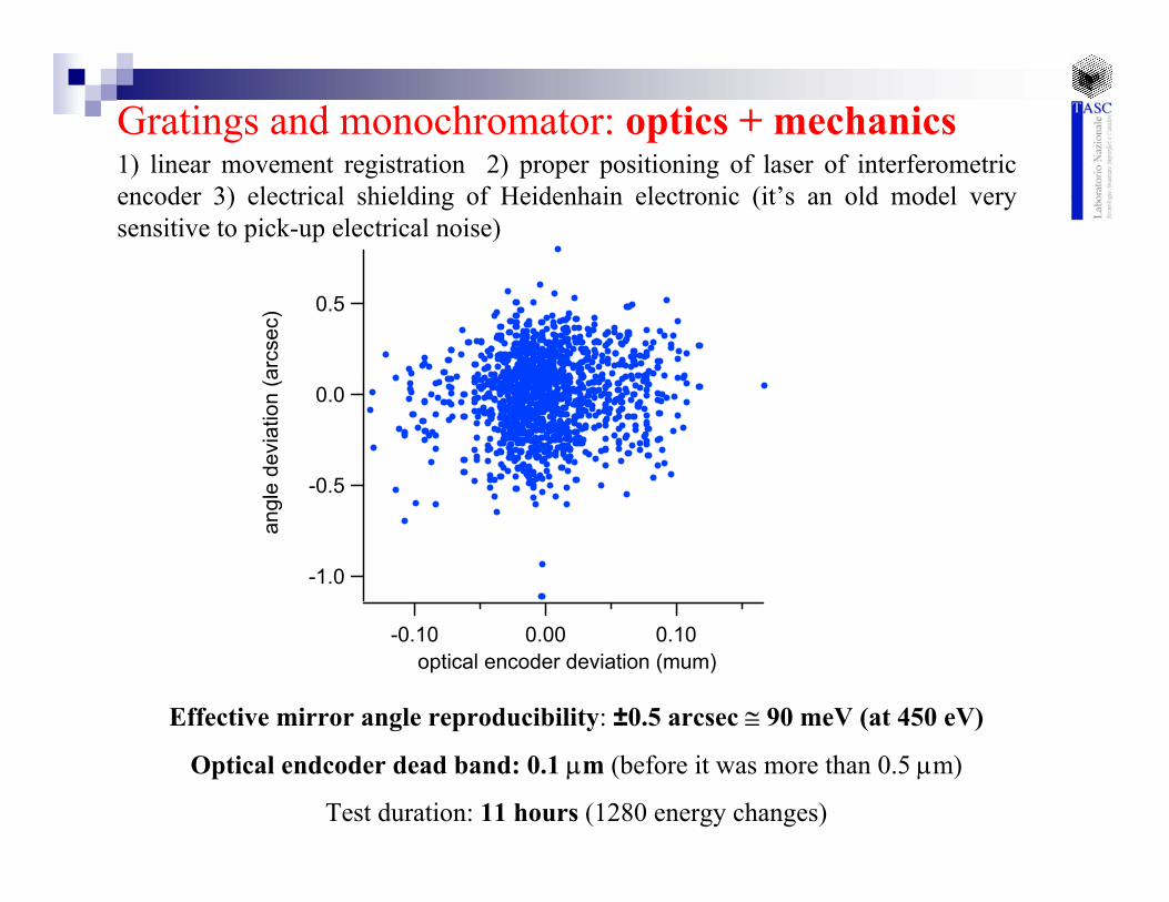
Gratings and monochromator: optics + mechanics
-1.0
-0.5
0.0
0.5an
gle
devi
atio
n (a
rcse
c)
0.100.00-0.10optical encoder deviation (mum)
Effective mirror angle reproducibility: ±0.5 arcsec ≅ 90 meV (at 450 eV)
Optical endcoder dead band: 0.1 µm (before it was more than 0.5 µm)
Test duration: 11 hours (1280 energy changes)
1) linear movement registration 2) proper positioning of laser of interferometric encoder 3) electrical shielding of Heidenhain electronic (it’s an old model very sensitive to pick-up electrical noise)
Gratings and monochromator: optics + mechanics

- (APPLE-II quasi-periodic undulator )125 mm period, 17 periods- Energy range:10-120 eV- Monochromator – variable line spacing PGM; ( gratings: 900 lines/mm, 1200 lines/mm, 1600 lines/mm), double track- Spot size ~100x50 µm2
- Open to users on 75% base1600 lines/mm1200 lines/mm, track 21200 lines/mm, track 1
APE – Low Energy Beamline – 10 -120 eV

Next Tuesday, 1st quasi-examChoose one energy range
Soft X-ray (till 1800 eV)XPS, XAS, XMCD
Representative beamline worldwideDefine your experiment
Describe CharacteristicsSource, optics, mono, experiments
1) Comment and questions2) Estimate costs
VUV (5-200 eV)ARPES
Hard X-ray (> 5 keV)Diffraction,Scattering,
other