Embed Size (px)
Citation preview
High-performance Multi-point Control System
SR Mini HG SYSTEM
Hardware Instruction Manual
SR Mini HG SYSTEM
IMSRM15-E6RKC INSTRUMENT INC. ®

All Rights Reserved, Copyright © 1996, RKC INSTRUMENT INC.
Modbus is a registered trademark of Schneider Electric. The name of each programmable controller (PLC) means the products of each manufacturer. Company names and product names used in this manual are the trademarks or registered trademarks of the respective companies.
IMSRM15-E6 i-1
Thank you for purchasing this RKC product. In order to achieve maximum performance and ensure proper operation of your new instrument, carefully read all the instructions in this manual. Please place the manual in a convenient location for easy reference.
SYMBOLS
: This mark indicates that all precautions should be taken for safe usage.
: This mark indicates important information on installation, handling and operating procedures.
: This mark indicates supplemental information on installation, handling and operating procedures.
: This mark indicates where additional information may be located.
To prevent injury to persons, damage to instrument and equipment, a suitable external protection device shall be required.
All wiring must be completed before power is turned on to prevent electric shock, fire or damage to instrument and equipment.
This instrument must be used in accordance with the specifications to prevent fire or damage to instrument and equipment.
This instrument is not intended for use in locations subject to flammable or explosive gases.
Do not touch high-voltage connections such as power supply terminals, etc. to avoid electric shock.
RKC is not responsible if this instrument is repaired, modified or disassembled by other than factory-approved personnel. Malfunction can occur and warranty is void under these conditions.
: This mark indicates precautions that must be taken if there is danger of electric shock, fire, etc., which could result in loss of life or injury.
: This mark indicates that if these precautions and operating procedures are not taken,
damage to the instrument may result.
WARNING!
CAUTION
WARNING
!
IMSRM15-E6 i-2
This product is intended for use with industrial machines, test and measuring equipment. (It is not designed for use with medical equipment and nuclear energy.)
This is a Class A instrument. In a domestic environment, this instrument may cause radio interference, in which case the user may be required to take additional measures.
This instrument is protected from electric shock by reinforced insulation. Provide reinforced insulation between the wire for the input signal and the wires for instrument power supply, source of power and loads.
Be sure to provide an appropriate surge control circuit respectively for the following: - If input/output or signal lines within the building are longer than 30 meters. - If input/output or signal lines leave the building, regardless the length.
This instrument is designed for installation in an enclosed instrumentation panel. All high-voltage connections such as power supply terminals must be enclosed in the instrumentation panel to avoid electric shock by operating personnel.
All precautions described in this manual should be taken to avoid damage to the instrument or equipment.
All wiring must be in accordance with local codes and regulations. All wiring must be completed before power is turned on to prevent electric shock, instrument failure,
or incorrect action. The power must be turned off before repairing work for input break and output failure including replacement of sensor, contactor or SSR, and all wiring must be completed before power is turned on again.
To prevent instrument damage as a result of failure, protect the power line and the input/output lines from high currents with a suitable overcurrent protection device with adequate breaking capacity such as fuse, circuit breaker, etc.
Prevent metal fragments or lead wire scraps from falling inside instrument case to avoid electric shock, fire or malfunction.
Tighten each terminal screw to the specified torque found in the manual to avoid electric shock, fire or malfunction.
For proper operation of this instrument, provide adequate ventilation for heat dispensation. Do not connect wires to unused terminals as this will interfere with proper operation of the
instrument. Turn off the power supply before cleaning the instrument. Do not use a volatile solvent such as paint thinner to clean the instrument. Deformation or
discoloration will occur. Use a soft, dry cloth to remove stains from the instrument. To avoid damage to instrument display, do not rub with an abrasive material or push front panel
with a hard object. Do not connect modular connectors to telephone line. When high alarm with hold action/re-hold action is used for Alarm function, alarm does not turn on
while hold action is in operation. Take measures to prevent overheating which may occur if the control device fails.
NOTICE This manual assumes that the reader has a fundamental knowledge of the principles of electricity, process
control, computer technology and communications. The figures, diagrams and numeric values used in this manual are only for purpose of illustration. RKC is not responsible for any damage or injury that is caused as a result of using this instrument, instrument
failure or indirect damage. RKC is not responsible for any damage and/or injury resulting from the use of instruments made by imitating
this instrument. Periodic maintenance is required for safe and proper operation of this instrument. Some components have a
limited service life, or characteristics that change over time. Every effort has been made to ensure accuracy of all information contained herein. RKC makes no warranty
expressed or implied, with respect to the accuracy of the information. The information in this manual is subject to change without prior notice.
No portion of this document may be reprinted, modified, copied, transmitted, digitized, stored, processed or retrieved through any mechanical, electronic, optical or other means without prior written approval from RKC.
CAUTION
IMSRM15-E6 i-3
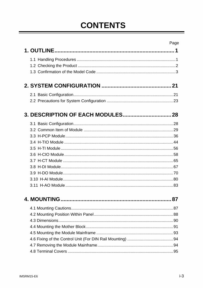
CONTENTS
Page
1. OUTLINE ............................................................................... 1 1.1 Handling Procedures ...................................................................................... 1 1.2 Checking the Product ..................................................................................... 2 1.3 Confirmation of the Model Code ..................................................................... 3
2. SYSTEM CONFIGURATION .............................................. 21
2.1 Basic Configuration ....................................................................................... 21 2.2 Precautions for System Configuration .......................................................... 23
3. DESCRIPTION OF EACH MODULES ................................ 28
3.1 Basic Configuration ....................................................................................... 28 3.2 Common Item of Module .............................................................................. 29 3.3 H-PCP Module .............................................................................................. 36 3.4 H-TIO Module ............................................................................................... 44 3.5 H-TI Module .................................................................................................. 56 3.6 H-CIO Module ............................................................................................... 58 3.7 H-CT Module ................................................................................................ 65 3.8 H-DI Module .................................................................................................. 67 3.9 H-DO Module ................................................................................................ 70 3.10 H-AI Module ................................................................................................ 80 3.11 H-AO Module .............................................................................................. 83
4. MOUNTING ......................................................................... 87
4.1 Mounting Cautions ......................................................................................... 87 4.2 Mounting Position Within Panel ..................................................................... 88 4.3 Dimensions .................................................................................................... 90 4.4 Mounting the Mother Block ............................................................................ 91 4.5 Mounting the Module Mainframe ................................................................... 93 4.6 Fixing of the Control Unit (For DIN Rail Mounting) ........................................ 94 4.7 Removing the Module Mainframe .................................................................. 94 4.8 Terminal Covers ............................................................................................ 95
IMSRM15-E6 i-4
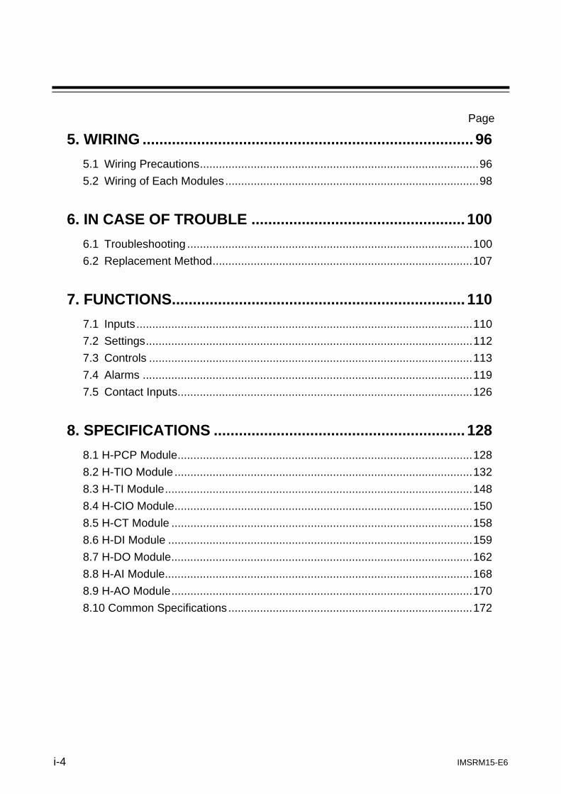
Page
5. WIRING ............................................................................... 96 5.1 Wiring Precautions ........................................................................................ 96 5.2 Wiring of Each Modules ................................................................................ 98
6. IN CASE OF TROUBLE ................................................... 100
6.1 Troubleshooting .......................................................................................... 100 6.2 Replacement Method .................................................................................. 107
7. FUNCTIONS ...................................................................... 110
7.1 Inputs .......................................................................................................... 110 7.2 Settings ....................................................................................................... 112 7.3 Controls ...................................................................................................... 113 7.4 Alarms ........................................................................................................ 119 7.5 Contact Inputs ............................................................................................. 126
8. SPECIFICATIONS ............................................................ 128
8.1 H-PCP Module ............................................................................................. 128 8.2 H-TIO Module .............................................................................................. 132 8.3 H-TI Module ................................................................................................. 148 8.4 H-CIO Module .............................................................................................. 150 8.5 H-CT Module ............................................................................................... 158 8.6 H-DI Module ................................................................................................ 159 8.7 H-DO Module ............................................................................................... 162 8.8 H-AI Module ................................................................................................. 168 8.9 H-AO Module ............................................................................................... 170 8.10 Common Specifications ............................................................................. 172
IMSRM15-E6 1
1. OUTLINE
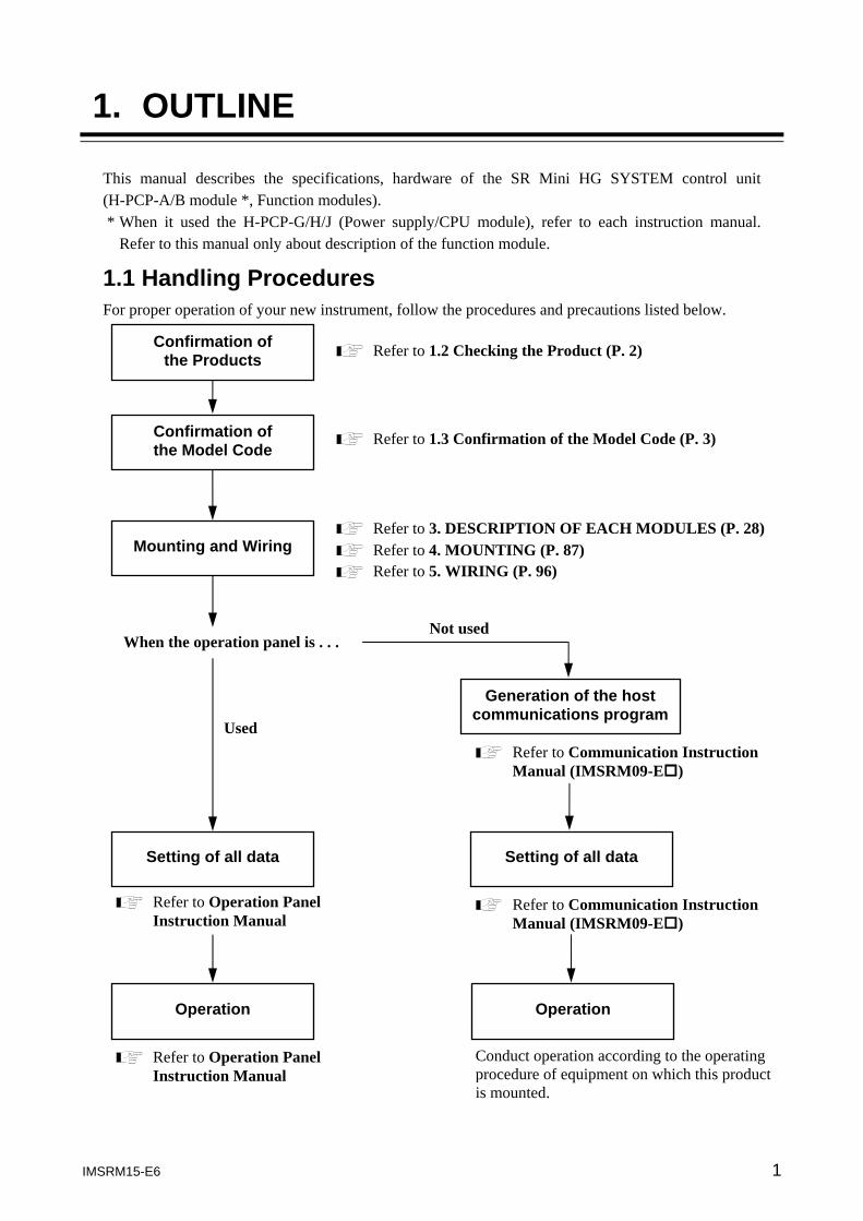
This manual describes the specifications, hardware of the SR Mini HG SYSTEM control unit (H-PCP-A/B module *, Function modules). * When it used the H-PCP-G/H/J (Power supply/CPU module), refer to each instruction manual.
Refer to this manual only about description of the function module. 1.1 Handling Procedures For proper operation of your new instrument, follow the procedures and precautions listed below.
When the operation panel is . . .
Refer to 1.2 Checking the Product (P. 2)
Refer to 1.3 Confirmation of the Model Code (P. 3)
Refer to 3. DESCRIPTION OF EACH MODULES (P. 28) Refer to 4. MOUNTING (P. 87)
Refer to Operation Panel Instruction Manual
Refer to Communication Instruction Manual (IMSRM09-E )
Refer to Operation Panel Instruction Manual
Refer to Communication Instruction Manual (IMSRM09-E )
Conduct operation according to the operating procedure of equipment on which this product is mounted.
Used
Not used
Refer to 5. WIRING (P. 96)
Confirmation of the Products
Confirmation of the Model Code
Mounting and Wiring
Setting of all data
Operation
Generation of the host communications program
Setting of all data
Operation
1. OUTLINE
IMSRM15-E6 2
1.2 Checking the Product When unpacking your new instrument, please confirm that the following products are included. If any of the products are missing, damaged, or if your manual is incomplete, contact your nearest RKC sales office or agent for replacement.
H-PCP-A/B module (Power supply/CPU module) .... 1 module H-PCP-A/B module is included in control unit. One H-PCP-A/B module (power supply/CPU module) is required for each control unit.
Function modules .... Required number of modules Function module is included in control unit.
DIN rail holding clips .... Two clips per unit
Hardware Quick Manual (IMS01V01-E□) .... 1 copy
Communication Quick Manual (IMS01V02-E□) .... 1 copy
Modules for the SR Mini HG SYSTEM cannot be mixed with those for the SR Mini SYSTEM.
1. OUTLINE
IMSRM15-E6 3
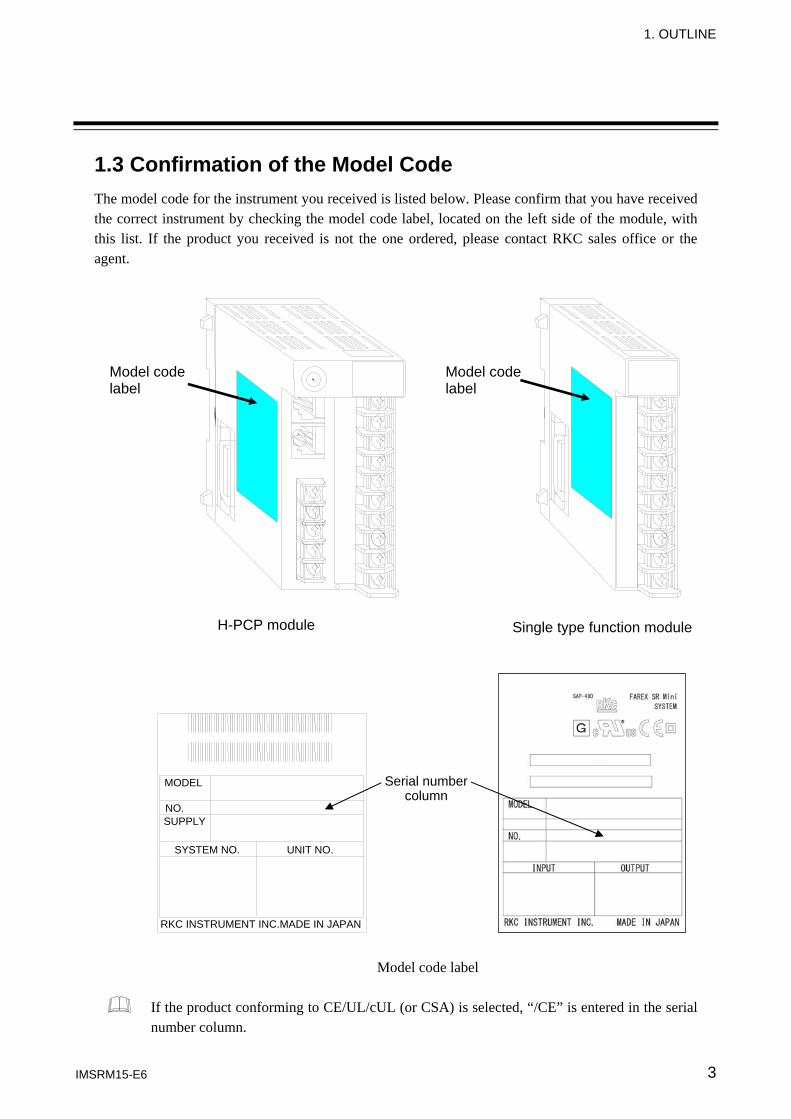
1.3 Confirmation of the Model Code The model code for the instrument you received is listed below. Please confirm that you have received the correct instrument by checking the model code label, located on the left side of the module, with this list. If the product you received is not the one ordered, please contact RKC sales office or the agent.
Model code label
If the product conforming to CE/UL/cUL (or CSA) is selected, “/CE” is entered in the serial number column.
Model code label
H-PCP module Single type function module
Model code label
Serial number column
MODEL
NO. SUPPLY
SYSTEM NO. UNIT NO.
RKC INSTRUMENT INC.MADE IN JAPAN
1. OUTLINE
IMSRM15-E6 4
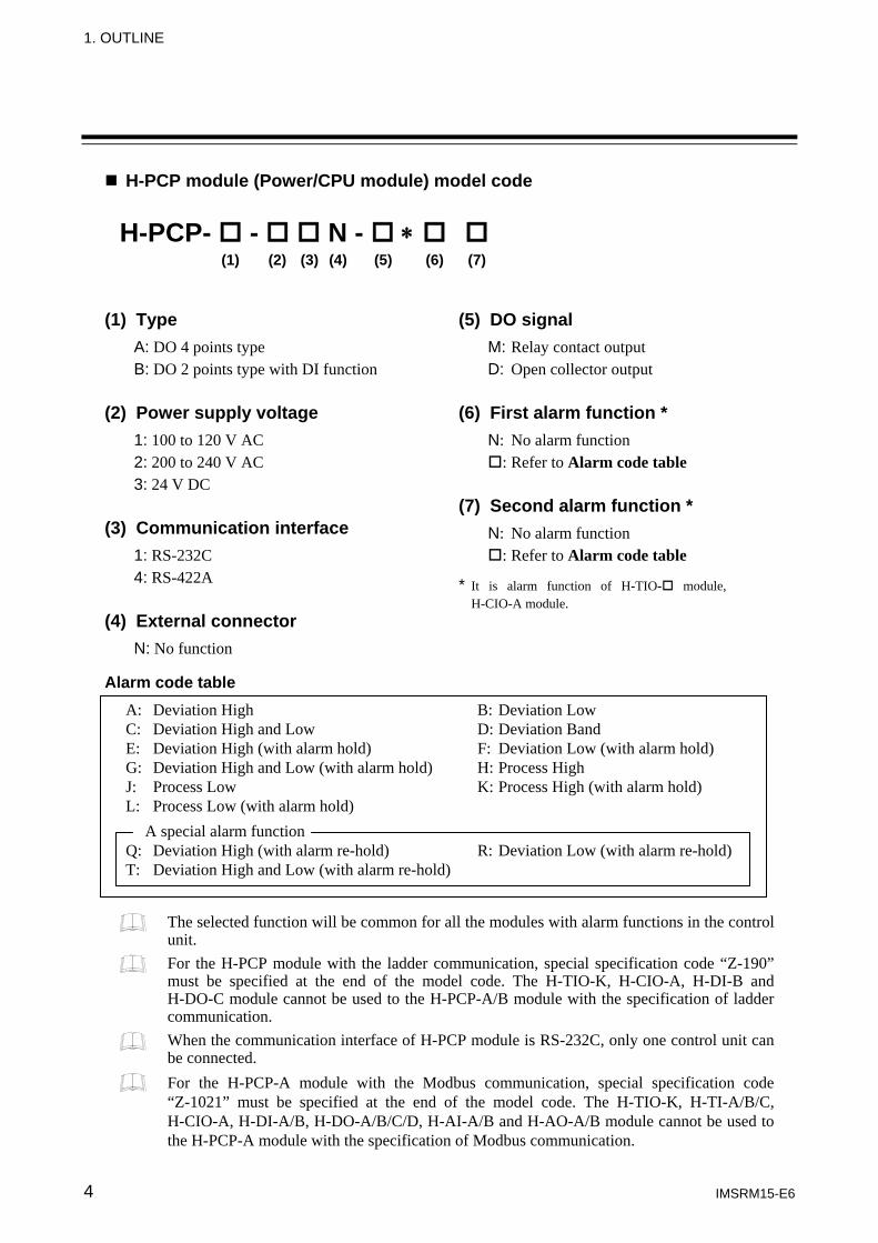
H-PCP module (Power/CPU module) model code (1) Type
A: DO 4 points type B: DO 2 points type with DI function
(2) Power supply voltage
1: 100 to 120 V AC 2: 200 to 240 V AC 3: 24 V DC
(3) Communication interface
1: RS-232C 4: RS-422A
(4) External connector N: No function
Alarm code table
The selected function will be common for all the modules with alarm functions in the control unit. For the H-PCP module with the ladder communication, special specification code “Z-190” must be specified at the end of the model code. The H-TIO-K, H-CIO-A, H-DI-B and H-DO-C module cannot be used to the H-PCP-A/B module with the specification of ladder communication. When the communication interface of H-PCP module is RS-232C, only one control unit can be connected. For the H-PCP-A module with the Modbus communication, special specification code “Z-1021” must be specified at the end of the model code. The H-TIO-K, H-TI-A/B/C, H-CIO-A, H-DI-A/B, H-DO-A/B/C/D, H-AI-A/B and H-AO-A/B module cannot be used to the H-PCP-A module with the specification of Modbus communication.
H-PCP- - N - ∗ (1) (2) (3) (4) (5) (6) (7)
(5) DO signal M: Relay contact output D: Open collector output
(6) First alarm function * N: No alarm function
: Refer to Alarm code table
(7) Second alarm function * N: No alarm function
: Refer to Alarm code table * It is alarm function of H-TIO- module,
H-CIO-A module.
A: Deviation High B: Deviation Low C: Deviation High and Low D: Deviation Band E: Deviation High (with alarm hold) F: Deviation Low (with alarm hold) G: Deviation High and Low (with alarm hold) H: Process High J: Process Low K: Process High (with alarm hold) L: Process Low (with alarm hold)
A special alarm function Q: Deviation High (with alarm re-hold) R: Deviation Low (with alarm re-hold) T: Deviation High and Low (with alarm re-hold)
1. OUTLINE
IMSRM15-E6 5
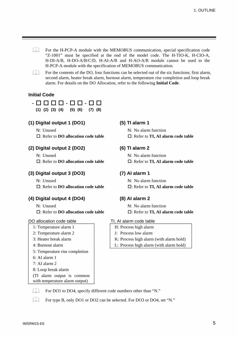
For the H-PCP-A module with the MEMOBUS communication, special specification code “Z-1001” must be specified at the end of the model code. The H-TIO-K, H-CIO-A, H-DI-A/B, H-DO-A/B/C/D, H-AI-A/B and H-AO-A/B module cannot be used to the H-PCP-A module with the specification of MEMOBUS communication. For the contents of the DO, four functions can be selected out of the six functions; first alarm, second alarm, heater break alarm, burnout alarm, temperature rise completion and loop break alarm. For details on the DO Allocation, refer to the following Initial Code.
Initial Code (1) Digital output 1 (DO1) (5) TI alarm 1
N: Unused N: No alarm function : Refer to DO allocation code table : Refer to TI, AI alarm code table
(2) Digital output 2 (DO2) (6) TI alarm 2
N: Unused N: No alarm function : Refer to DO allocation code table : Refer to TI, AI alarm code table
(3) Digital output 3 (DO3) (7) AI alarm 1
N: Unused N: No alarm function : Refer to DO allocation code table : Refer to TI, AI alarm code table
(4) Digital output 4 (DO4) (8) AI alarm 2
N: Unused N: No alarm function : Refer to DO allocation code table : Refer to TI, AI alarm code table
DO allocation code table TI, AI alarm code table
1: Temperature alarm 1 H: Process high alarm 2: Temperature alarm 2 J: Process low alarm 3: Heater break alarm K: Process high alarm (with alarm hold) 4: Burnout alarm L: Process high alarm (with alarm hold) 5: Temperature rise completion 6: AI alarm 1 7: AI alarm 2 8: Loop break alarm (TI alarm output is common with temperature alarm output)
For DO1 to DO4, specify different code numbers other than “N.”
For type B, only DO1 or DO2 can be selected. For DO3 or DO4, set “N.”
- - - (1) (2) (3) (4) (5) (6) (7) (8)
1. OUTLINE
IMSRM15-E6 6
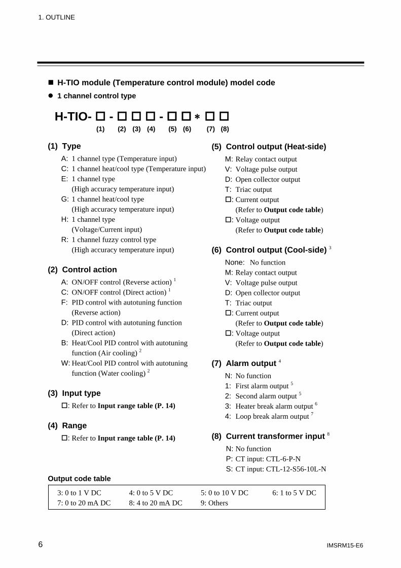
H-TIO module (Temperature control module) model code 1 channel control type
(1) Type
A: 1 channel type (Temperature input) C: 1 channel heat/cool type (Temperature input) E: 1 channel type (High accuracy temperature input) G: 1 channel heat/cool type (High accuracy temperature input) H: 1 channel type (Voltage/Current input) R: 1 channel fuzzy control type (High accuracy temperature input)
(2) Control action
A: ON/OFF control (Reverse action) 1 C: ON/OFF control (Direct action) 1 F: PID control with autotuning function (Reverse action) D: PID control with autotuning function (Direct action) B: Heat/Cool PID control with autotuning function (Air cooling) 2 W: Heat/Cool PID control with autotuning function (Water cooling) 2
(3) Input type
: Refer to Input range table (P. 14) (4) Range
: Refer to Input range table (P. 14) Output code table
3: 0 to 1 V DC 4: 0 to 5 V DC 5: 0 to 10 V DC 6: 1 to 5 V DC 7: 0 to 20 mA DC 8: 4 to 20 mA DC 9: Others
H-TIO- - - ∗ (1) (2) (3) (4) (5) (6) (7) (8)
(5) Control output (Heat-side) M: Relay contact output V: Voltage pulse output D: Open collector output T: Triac output
: Current output (Refer to Output code table)
: Voltage output (Refer to Output code table)
(6) Control output (Cool-side) 3 None: No function M: Relay contact output V: Voltage pulse output D: Open collector output T: Triac output
: Current output (Refer to Output code table)
: Voltage output (Refer to Output code table)
(7) Alarm output 4 N: No function 1: First alarm output 5 2: Second alarm output 5 3: Heater break alarm output 6 4: Loop break alarm output 7
(8) Current transformer input 8
N: No function P: CT input: CTL-6-P-N S: CT input: CTL-12-S56-10L-N
1. OUTLINE
IMSRM15-E6 7
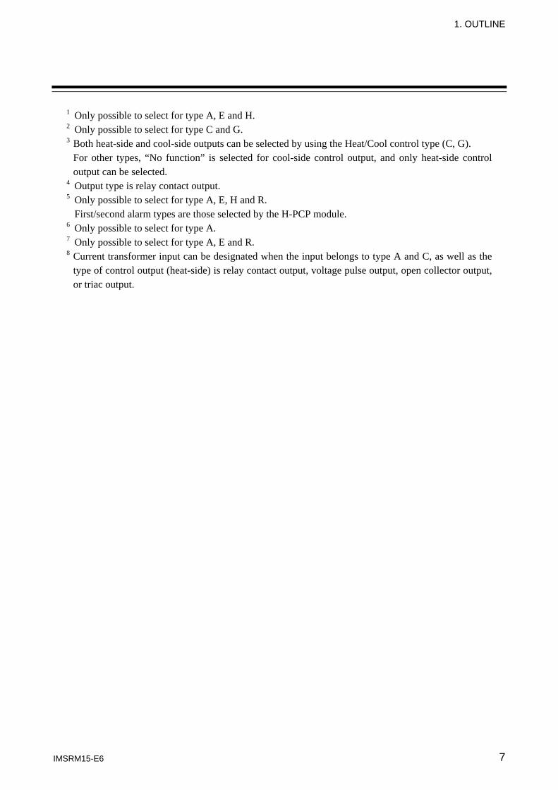
1 Only possible to select for type A, E and H. 2 Only possible to select for type C and G. 3 Both heat-side and cool-side outputs can be selected by using the Heat/Cool control type (C, G).
For other types, “No function” is selected for cool-side control output, and only heat-side control output can be selected.
4 Output type is relay contact output. 5 Only possible to select for type A, E, H and R. First/second alarm types are those selected by the H-PCP module. 6 Only possible to select for type A. 7 Only possible to select for type A, E and R. 8 Current transformer input can be designated when the input belongs to type A and C, as well as the
type of control output (heat-side) is relay contact output, voltage pulse output, open collector output, or triac output.
1. OUTLINE
IMSRM15-E6 8
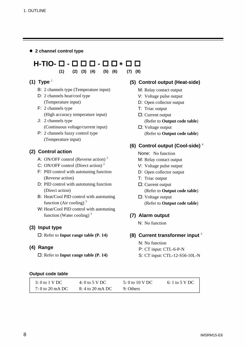
2 channel control type (1) Type 1
B: 2 channels type (Temperature input) D: 2 channels heat/cool type (Temperature input) F: 2 channels type (High accuracy temperature input) J: 2 channels type (Continuous voltage/current input) P: 2 channels fuzzy control type (Temperature input)
(2) Control action
A: ON/OFF control (Reverse action) 2 C: ON/OFF control (Direct action) 2 F: PID control with autotuning function (Reverse action) D: PID control with autotuning function (Direct action) B: Heat/Cool PID control with autotuning function (Air cooling) 3 W: Heat/Cool PID control with autotuning function (Water cooling) 3
(3) Input type
: Refer to Input range table (P. 14) (4) Range
: Refer to Input range table (P. 14) Output code table
3: 0 to 1 V DC 4: 0 to 5 V DC 5: 0 to 10 V DC 6: 1 to 5 V DC 7: 0 to 20 mA DC 8: 4 to 20 mA DC 9: Others
H-TIO- - - ∗ (1) (2) (3) (4) (5) (6) (7) (8)
(5) Control output (Heat-side) M: Relay contact output V: Voltage pulse output D: Open collector output T: Triac output
: Current output (Refer to Output code table)
: Voltage output (Refer to Output code table)
(6) Control output (Cool-side) 4 None: No function M: Relay contact output V: Voltage pulse output D: Open collector output T: Triac output
: Current output (Refer to Output code table)
: Voltage output (Refer to Output code table)
(7) Alarm output N: No function
(8) Current transformer input 5
N: No function P: CT input: CTL-6-P-N S: CT input: CTL-12-S56-10L-N
1. OUTLINE
IMSRM15-E6 9
1 In two channels type, the inputs, ranges and outputs should be identical. Both inputs of H-TIO-F module are only RTD inputs.
2 Only possible to select for type B and F. 3 Only possible to select for type D. 4 Both heat-side and cool-side outputs can be selected by using the Heat/Cool control type (D).
For other types, “No function” is selected for cool-side control output, and only heat-side control output can be selected.
5 Current transformer input can be designated when the input belongs to type D, as well as the type of control output (heat-side) is relay contact output, voltage pulse output, open collector output, or triac output.
1. OUTLINE
IMSRM15-E6 10
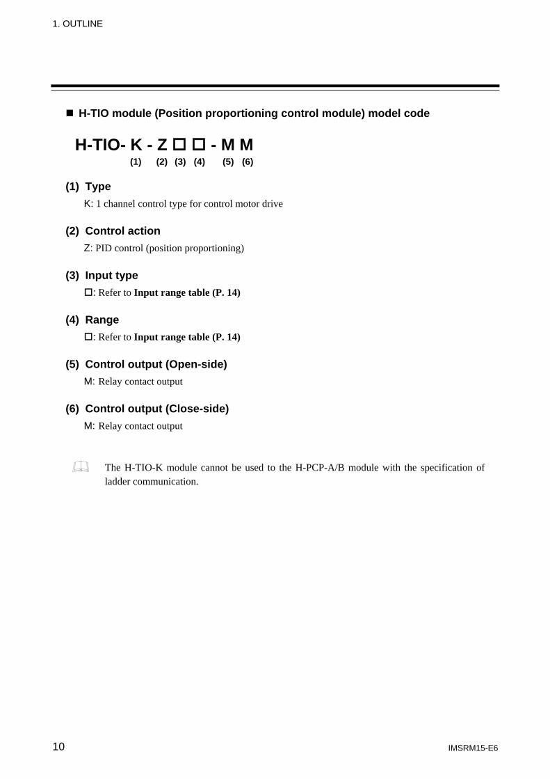
H-TIO module (Position proportioning control module) model code (1) Type
K: 1 channel control type for control motor drive (2) Control action
Z: PID control (position proportioning) (3) Input type
: Refer to Input range table (P. 14) (4) Range
: Refer to Input range table (P. 14) (5) Control output (Open-side)
M: Relay contact output
(6) Control output (Close-side) M: Relay contact output
The H-TIO-K module cannot be used to the H-PCP-A/B module with the specification of ladder communication.
H-TIO- K - Z - M M (1) (2) (3) (4) (5) (6)
1. OUTLINE
IMSRM15-E6 11
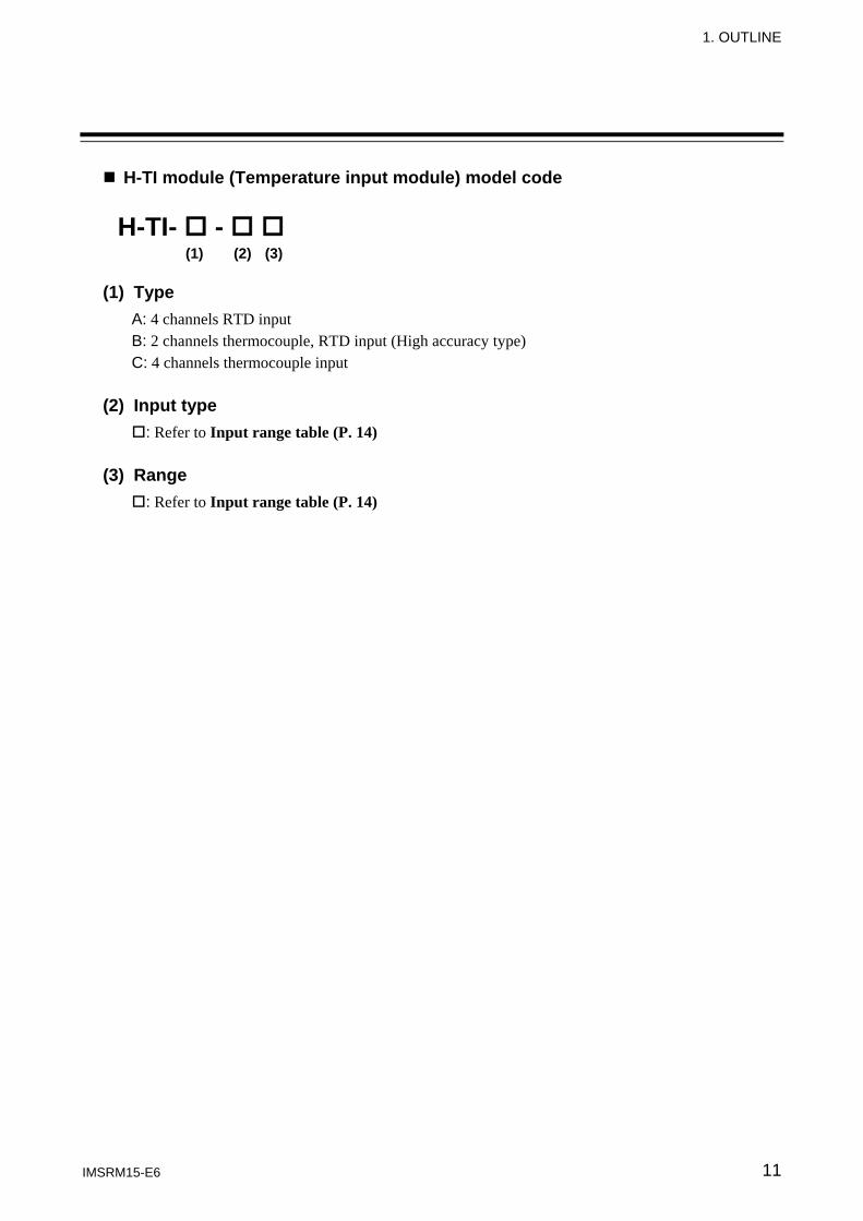
H-TI module (Temperature input module) model code (1) Type
A: 4 channels RTD input B: 2 channels thermocouple, RTD input (High accuracy type) C: 4 channels thermocouple input
(2) Input type
: Refer to Input range table (P. 14) (3) Range
: Refer to Input range table (P. 14)
H-TI- - (1) (2) (3)
1. OUTLINE
IMSRM15-E6 12
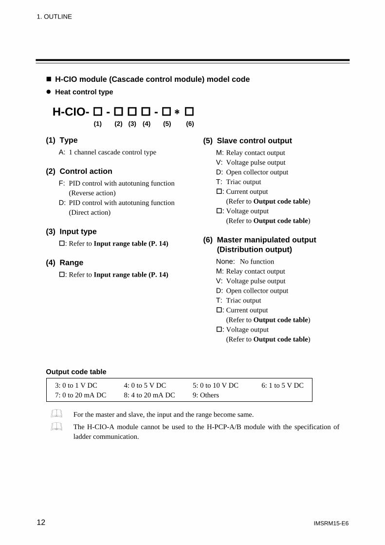
H-CIO module (Cascade control module) model code Heat control type
(1) Type
A: 1 channel cascade control type (2) Control action
F: PID control with autotuning function (Reverse action) D: PID control with autotuning function (Direct action)
(3) Input type
: Refer to Input range table (P. 14) (4) Range
: Refer to Input range table (P. 14) Output code table
3: 0 to 1 V DC 4: 0 to 5 V DC 5: 0 to 10 V DC 6: 1 to 5 V DC 7: 0 to 20 mA DC 8: 4 to 20 mA DC 9: Others
For the master and slave, the input and the range become same.
The H-CIO-A module cannot be used to the H-PCP-A/B module with the specification of ladder communication.
H-CIO- - - ∗ (1) (2) (3) (4) (5) (6)
(5) Slave control output M: Relay contact output V: Voltage pulse output D: Open collector output T: Triac output
: Current output (Refer to Output code table)
: Voltage output (Refer to Output code table)
(6) Master manipulated output (Distribution output) None: No function M: Relay contact output V: Voltage pulse output D: Open collector output T: Triac output
: Current output (Refer to Output code table)
: Voltage output (Refer to Output code table)
1. OUTLINE
IMSRM15-E6 13
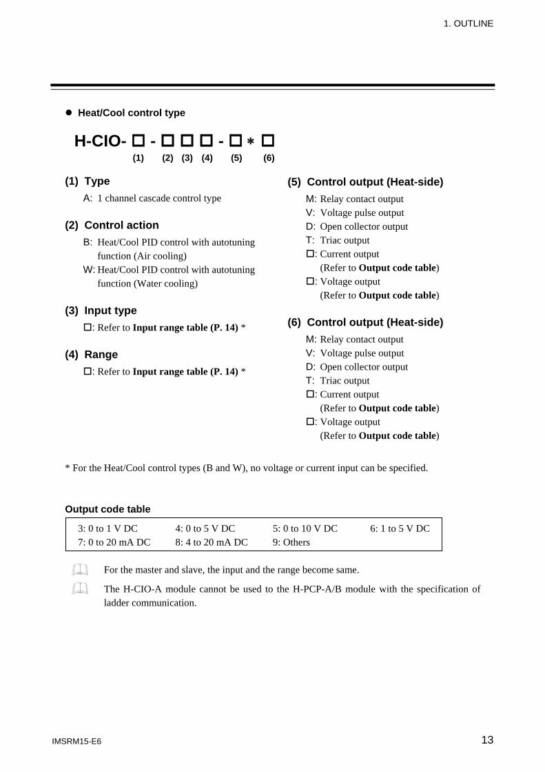
Heat/Cool control type (1) Type
A: 1 channel cascade control type (2) Control action
B: Heat/Cool PID control with autotuning function (Air cooling) W: Heat/Cool PID control with autotuning function (Water cooling)
(3) Input type
: Refer to Input range table (P. 14) * (4) Range
: Refer to Input range table (P. 14) * * For the Heat/Cool control types (B and W), no voltage or current input can be specified. Output code table
3: 0 to 1 V DC 4: 0 to 5 V DC 5: 0 to 10 V DC 6: 1 to 5 V DC 7: 0 to 20 mA DC 8: 4 to 20 mA DC 9: Others
For the master and slave, the input and the range become same.
The H-CIO-A module cannot be used to the H-PCP-A/B module with the specification of ladder communication.
H-CIO- - - ∗ (1) (2) (3) (4) (5) (6)
(5) Control output (Heat-side) M: Relay contact output V: Voltage pulse output D: Open collector output T: Triac output
: Current output (Refer to Output code table)
: Voltage output (Refer to Output code table)
(6) Control output (Heat-side) M: Relay contact output V: Voltage pulse output D: Open collector output T: Triac output
: Current output (Refer to Output code table)
: Voltage output (Refer to Output code table)
1. OUTLINE
IMSRM15-E6 14
Input range table
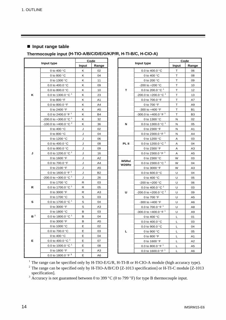
Thermocouple input
Input type Code
Input Range 0 to 400 °C K 02
0 to 800 °C K 04
0 to 1300 °C K 11
0.0 to 400.0 °C K 09
0.0 to 800.0 °C K 10
K 0.0 to 1300.0 °C 1 K 23
0 to 800 °F K A1
0.0 to 800.0 °F K A4
0 to 2400 °F K A5
0.0 to 2400.0 °F 1 K B4
-200.0 to +300.0 °C 1 K 32
-100.0 to +400.0 °C 2 K 36
0 to 400 °C J 02
0 to 800 °C J 04
0 to 1200 °C J 06
0.0 to 400.0 °C J 08
0.0 to 800.0 °C J 09
J 0.0 to 1200.0 °C 1 J 16
0 to 1600 °F J A2
0.0 to 700.0 °F J A4
0 to 2100 °F J A5
0.0 to 1600.0 °F 1 J B2
-200.0 to +300.0 °C 1 J 26
0 to 1700 °C R 03
R 0.0 to 1700.0 °C 1 R 05
0 to 3000 °F R A3
0 to 1700 °C S 03
S 0.0 to 1700.0 °C 1 S 04
0 to 3000 °F S A3
0 to 1800 °C B 03
B 3 0.0 to 1800.0 °C 1 B 04
0 to 3000 °F B A5
0 to 1000 °C E 02
0.0 to 700.0 °C E 03
0 to 400 °C E 04
E 0.0 to 400.0 °C 1 E 07
0.0 to 1000.0 °C 1 E 08
0 to 1800 °F E A3
0.0 to 1800.0 °F 1 E A6
Input type Code
Input Range 0.0 to 400.0 °C T 06
0 to 400 °C T 08
0 to 200 °C T 09
-200 to +200 °C T 10
T 0.0 to 200.0 °C 1 T 12
-200.0 to +200.0 °C 1 T 13
0.0 to 700.0 °F T A7
0 to 700 °F T A9
-300 to +400 °F T B1
-300.0 to +400.0 °F 1 T B3
0 to 1300 °C N 02
N 0.0 to 1300.0 °C 1 N 05
0 to 2300 °F N A1
0.0 to 2300.0 °F 1 N A4
0 to 1200 °C A 03
PL II 0.0 to 1200.0 °C 1 A 04
0 to 2300 °F A A3
0.0 to 2300.0 °F 1 A A5
W5Re/ W26Re
0 to 2300 °C W 03
0.0 to 2300.0 °C 1 W 04
0 to 3000 °F W A3
0.0 to 600.0 °C U 04
0 to 400 °C U 05
-200 to +200 °C U 06
0.0 to 400.0 °C 1 U 03
U -200.0 to +200.0 °C 1 U 09
0 to 700 °F U A5
-300 to +400 °F U A6
0.0 to 700.0 °F 1 U A8
-300.0 to +400.0 °F 1 U A9
0 to 400 °C L 01
0.0 to 400.0 °C L 03
0.0 to 900.0 °C L 04
L 0 to 900 °C L 05
0 to 800 °F L A1
0 to 1600 °F L A2
0.0 to 800.0 °F 1 L A5
0.0 to 1600.0 °F 1 L A6
1 The range can be specified only by H-TIO-E/G/R, H-TI-B or H-CIO-A module (high accuracy type). 2 The range can be specified only by H-TIO-A/B/C/D [Z-1013 specification] or H-TI-C module [Z-1013 specification].
3 Accuracy is not guaranteed between 0 to 399 °C (0 to 799 °F) for type B thermocouple input.
(H-TIO-A/B/C/D/E/G/K/P/R, H-TI-B/C, H-CIO-A)
1. OUTLINE
IMSRM15-E6 15
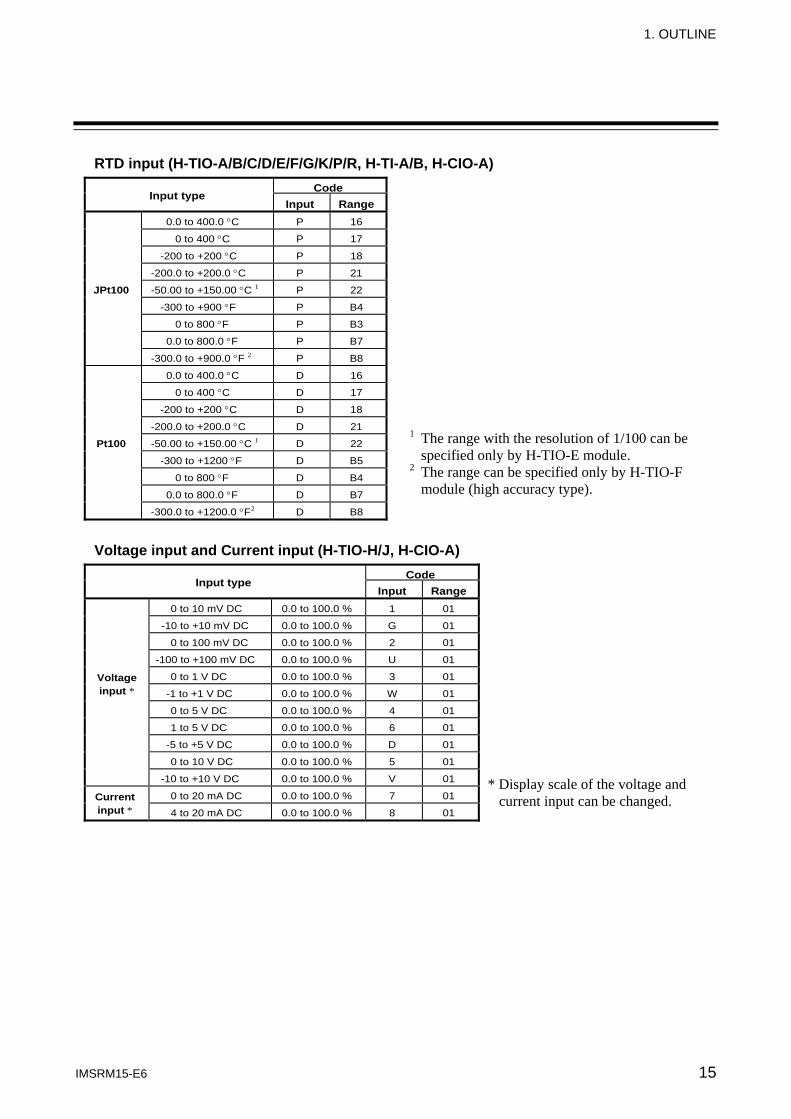
RTD input (H-TIO-A/B/C/D/E/F/G/K/P/R, H-TI-A/B, H-CIO-A)
Input type Code
Input Range 0.0 to 400.0 °C P 16
0 to 400 °C P 17
-200 to +200 °C P 18
-200.0 to +200.0 °C P 21
JPt100 -50.00 to +150.00 °C 1 P 22
-300 to +900 °F P B4
0 to 800 °F P B3
0.0 to 800.0 °F P B7
-300.0 to +900.0 °F 2 P B8
0.0 to 400.0 °C D 16
0 to 400 °C D 17
-200 to +200 °C D 18
-200.0 to +200.0 °C D 21
Pt100 -50.00 to +150.00 °C 1 D 22
-300 to +1200 °F D B5
0 to 800 °F D B4
0.0 to 800.0 °F D B7
-300.0 to +1200.0 °F 2 D B8
Voltage input and Current input (H-TIO-H/J, H-CIO-A)
Input type Code
Input Range 0 to 10 mV DC 0.0 to 100.0 % 1 01
-10 to +10 mV DC 0.0 to 100.0 % G 01
0 to 100 mV DC 0.0 to 100.0 % 2 01
-100 to +100 mV DC 0.0 to 100.0 % U 01
Voltage input *
0 to 1 V DC 0.0 to 100.0 % 3 01
-1 to +1 V DC 0.0 to 100.0 % W 01
0 to 5 V DC 0.0 to 100.0 % 4 01
1 to 5 V DC 0.0 to 100.0 % 6 01
-5 to +5 V DC 0.0 to 100.0 % D 01
0 to 10 V DC 0.0 to 100.0 % 5 01
-10 to +10 V DC 0.0 to 100.0 % V 01
Current input *
0 to 20 mA DC 0.0 to 100.0 % 7 01
4 to 20 mA DC 0.0 to 100.0 % 8 01
* Display scale of the voltage and current input can be changed.
1 The range with the resolution of 1/100 can be specified only by H-TIO-E module.
2 The range can be specified only by H-TIO-F module (high accuracy type).
1. OUTLINE
IMSRM15-E6 16
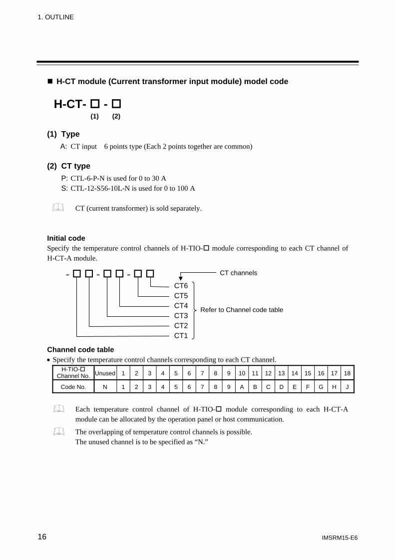
H-CT module (Current transformer input module) model code (1) Type
A: CT input 6 points type (Each 2 points together are common) (2) CT type
P: CTL-6-P-N is used for 0 to 30 A S: CTL-12-S56-10L-N is used for 0 to 100 A
CT (current transformer) is sold separately.
Initial code Specify the temperature control channels of H-TIO- module corresponding to each CT channel of H-CT-A module.
- - - CT6 CT5 CT4 CT3 CT2 CT1
Channel code table • Specify the temperature control channels corresponding to each CT channel.
H-TIO- Channel No. Unused 1 2 3 4 5 6 7 8 9 10 11 12 13 14 15 16 17 18
Code No. N 1 2 3 4 5 6 7 8 9 A B C D E F G H J
Each temperature control channel of H-TIO- module corresponding to each H-CT-A module can be allocated by the operation panel or host communication.
The overlapping of temperature control channels is possible. The unused channel is to be specified as “N.”
H-CT- - (1) (2)
CT channels
Refer to Channel code table
1. OUTLINE
IMSRM15-E6 17
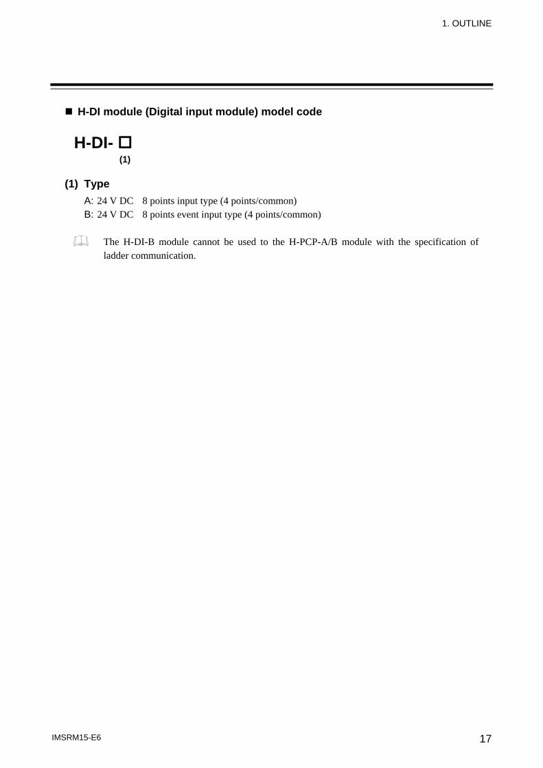
H-DI module (Digital input module) model code (1) Type
A: 24 V DC 8 points input type (4 points/common) B: 24 V DC 8 points event input type (4 points/common)
The H-DI-B module cannot be used to the H-PCP-A/B module with the specification of ladder communication.
H-DI- (1)
1. OUTLINE
IMSRM15-E6 18
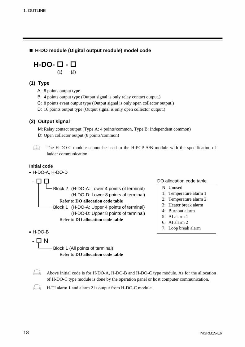
H-DO module (Digital output module) model code (1) Type
A: 8 points output type B: 4 points output type (Output signal is only relay contact output.) C: 8 points event output type (Output signal is only open collector output.) D: 16 points output type (Output signal is only open collector output.)
(2) Output signal
M: Relay contact output (Type A: 4 points/common, Type B: Independent common) D: Open collector output (8 points/common)
The H-DO-C module cannot be used to the H-PCP-A/B module with the specification of ladder communication.
Initial code • H-DO-A, H-DO-D
- Block 2 (H-DO-A: Lower 4 points of terminal) (H-DO-D: Lower 8 points of terminal) Refer to DO allocation code table Block 1 (H-DO-A: Upper 4 points of terminal) (H-DO-D: Upper 8 points of terminal) Refer to DO allocation code table
• H-DO-B
- N Block 1 (All points of terminal) Refer to DO allocation code table
Above initial code is for H-DO-A, H-DO-B and H-DO-C type module. As for the allocation of H-DO-C type module is done by the operation panel or host computer communication.
H-TI alarm 1 and alarm 2 is output from H-DO-C module.
H-DO- - (1) (2)
N: Unused 1: Temperature alarm 1 2: Temperature alarm 2 3: Heater break alarm 4: Burnout alarm 5: AI alarm 1 6: AI alarm 2 7: Loop break alarm
DO allocation code table
1. OUTLINE
IMSRM15-E6 19
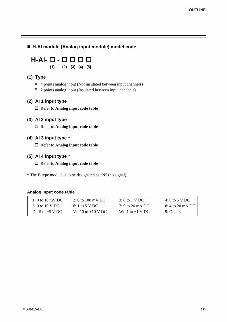
H-AI module (Analog input module) model code (1) Type
A: 4 points analog input (Not insulated between input channels) B: 2 points analog input (Insulated between input channels)
(2) AI 1 input type
: Refer to Analog input code table (3) AI 2 input type
: Refer to Analog input code table (4) AI 3 input type *
: Refer to Analog input code table (5) AI 4 input type *
: Refer to Analog input code table * The B type module is to be designated as “N” (no signal). Analog input code table
1: 0 to 10 mV DC 2: 0 to 100 mV DC 3: 0 to 1 V DC 4: 0 to 5 V DC 5: 0 to 10 V DC 6: 1 to 5 V DC 7: 0 to 20 mA DC 8: 4 to 20 mA DC D: -5 to +5 V DC V: -10 to +10 V DC W: -1 to +1 V DC 9: Others
H-AI- - (1) (2) (3) (4) (5)
1. OUTLINE
IMSRM15-E6 20
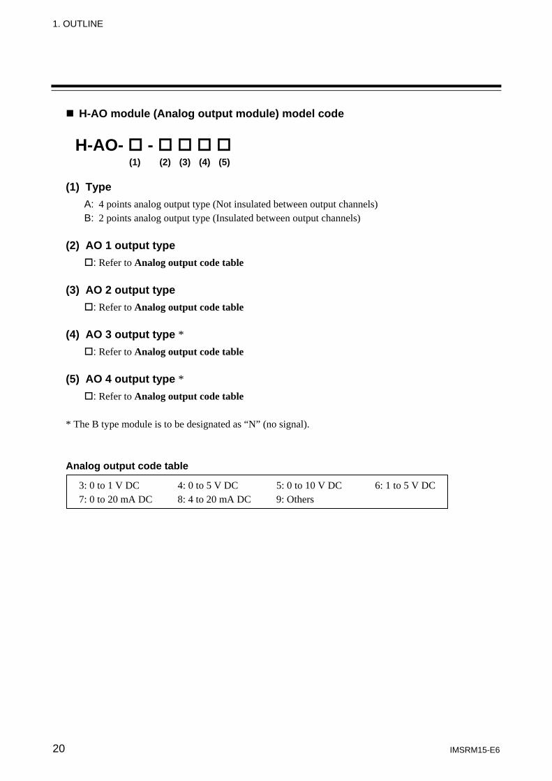
H-AO module (Analog output module) model code (1) Type
A: 4 points analog output type (Not insulated between output channels) B: 2 points analog output type (Insulated between output channels)
(2) AO 1 output type
: Refer to Analog output code table (3) AO 2 output type
: Refer to Analog output code table (4) AO 3 output type *
: Refer to Analog output code table (5) AO 4 output type *
: Refer to Analog output code table * The B type module is to be designated as “N” (no signal). Analog output code table
3: 0 to 1 V DC 4: 0 to 5 V DC 5: 0 to 10 V DC 6: 1 to 5 V DC 7: 0 to 20 mA DC 8: 4 to 20 mA DC 9: Others
H-AO- - (1) (2) (3) (4) (5)
IMSRM15-E6 21
2. SYSTEM CONFIGURATION
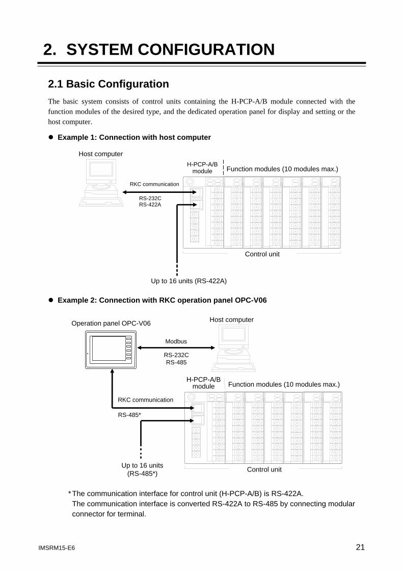
2.1 Basic Configuration The basic system consists of control units containing the H-PCP-A/B module connected with the function modules of the desired type, and the dedicated operation panel for display and setting or the host computer.
Example 1: Connection with host computer
Example 2: Connection with RKC operation panel OPC-V06
* The communication interface for control unit (H-PCP-A/B) is RS-422A. The communication interface is converted RS-422A to RS-485 by connecting modular connector for terminal.
H-PCP-A/Bmodule
Host computer
Function modules (10 modules max.)
Control unit
Up to 16 units (RS-422A)
RKC communication
RS-232C RS-422A
Host computer
Modbus
RS-232CRS-485
H-PCP-A/Bmodule Function modules (10 modules max.)
Control unit Up to 16 units (RS-485*)
RS-485*
Operation panel OPC-V06
RKC communication
2. SYSTEM CONFIGURATION
IMSRM15-E6 22
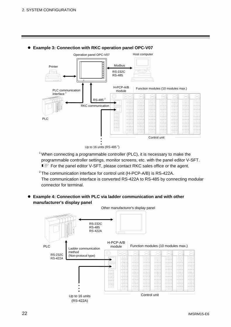
Example 3: Connection with RKC operation panel OPC-V07
1 When connecting a programmable controller (PLC), it is necessary to make the programmable controller settings, monitor screens, etc. with the panel editor V-SFT.
For the panel editor V-SFT, please contact RKC sales office or the agent.
2 The communication interface for control unit (H-PCP-A/B) is RS-422A. The communication interface is converted RS-422A to RS-485 by connecting modular connector for terminal.
Example 4: Connection with PLC via ladder communication and with other manufacturer's display panel
RS-232CRS-485 RS-422A
RS-232C RS-422A
PLC
Other manufacturer's display panel
H-PCP-A/Bmodule Function modules (10 modules max.)
Control unit Up to 16 units (RS-422A)
Ladder communication method (Non-protocol type)
Host computer Operation panel OPC-V07
RKC communication
RS-485 2
Up to 16 units (RS-485 2)
H-PCP-A/B module
Function modules (10 modules max.)
Control unit
RS-232CRS-485
Printer
PLC
PLC communication interface 1
Modbus
2. SYSTEM CONFIGURATION
IMSRM15-E6 23
2.2 Precautions for System Configuration
If you add or delete a function module, or change the arrangement of the modules, or replace a module with a different model, be sure to perform “Module initialization (identifier CL)” before setting the data. “Module initialization” stores the new module configuration in the H-PCP module. If data is set before “Module initialization” is performed, the H-PCP module will set the previously stored initial data of the old modules in the new modules, which may cause malfunction.
For details on how to initialize the module, Refer to SR Mini/SR Mini HG SYSTEM Supplementary Information Initialize Settings [Extended Communications] (IMSRM07-E ).
The above manual can be downloaded from the official RKC website: http://www.rkcinst.com/english/manual_load.htm
When configuring or extending the system, observe the following precautions.
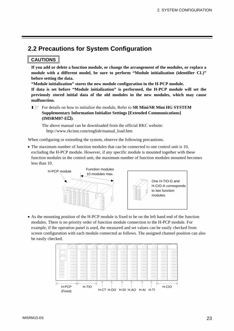
• The maximum number of function modules that can be connected to one control unit is 10, excluding the H-PCP module. However, if any specific module is mounted together with these function modules in the control unit, the maximum number of function modules mounted becomes less than 10.
• As the mounting position of the H-PCP module is fixed to be on the left hand end of the function
modules. There is no priority order of function module connection to the H-PCP module. For example, if the operation panel is used, the measured and set values can be easily checked from screen configuration with each module connected as follows. The assigned channel position can also be easily checked.
H-TIO H-CT H-DO H-DI H-AO H-AI
H-PCP(Fixed) H-TI
H-CIO
Function modules10 modules max.
H-PCP module
One H-TIO-D and H-CIO-A corresponds to two function modules.
CAUTIONS
2. SYSTEM CONFIGURATION
IMSRM15-E6 24
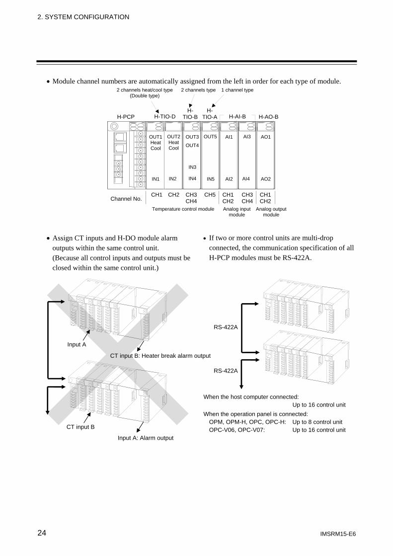
Input A
CT input B
Input A: Alarm output
CT input B: Heater break alarm output
• Module channel numbers are automatically assigned from the left in order for each type of module.
IN1 IN2
H-PCP H-TIO-DH-
TIO-A H-AI-B H-AO-B
Channel No. CH1 CH2 CH3
CH4CH5 CH1
CH2CH3CH4
CH1CH2
H- TIO-B
OUT1 Heat Cool
OUT2HeatCool
IN3
IN4 IN5
OUT3
OUT4
OUT5
AI2 AI4
AI1 AI3
AO2
AO1
2 channels heat/cool type (Double type)
2 channels type 1 channel type
Temperature control module Analog inputmodule
Analog output module
• Assign CT inputs and H-DO module alarm outputs within the same control unit. (Because all control inputs and outputs must be closed within the same control unit.)
RS-422A
RS-422A
When the host computer connected: Up to 16 control unit
When the operation panel is connected: OPM, OPM-H, OPC, OPC-H: Up to 8 control unit OPC-V06, OPC-V07: Up to 16 control unit
• If two or more control units are multi-drop connected, the communication specification of all H-PCP modules must be RS-422A.
2. SYSTEM CONFIGURATION
IMSRM15-E6 25
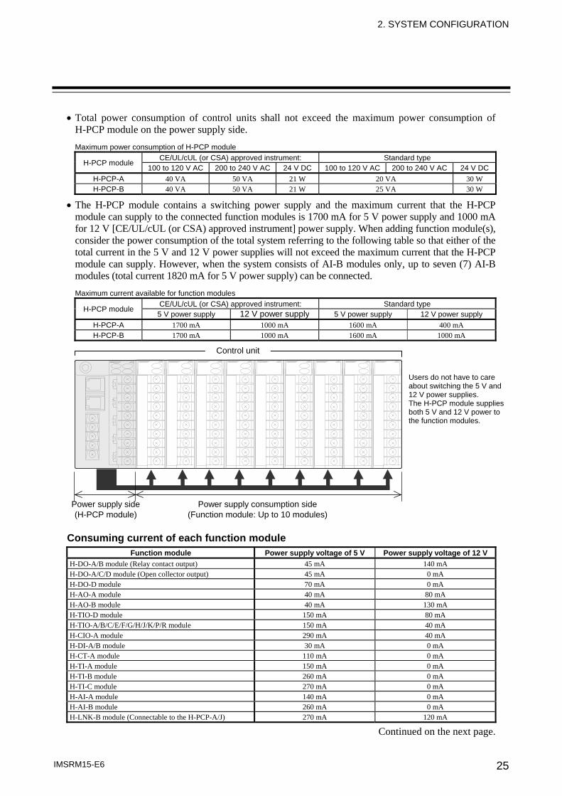
• Total power consumption of control units shall not exceed the maximum power consumption of H-PCP module on the power supply side. Maximum power consumption of H-PCP module
H-PCP module CE/UL/cUL (or CSA) approved instrument: Standard type
100 to 120 V AC 200 to 240 V AC 24 V DC 100 to 120 V AC 200 to 240 V AC 24 V DCH-PCP-A 40 VA 50 VA 21 W 20 VA 30 W H-PCP-B 40 VA 50 VA 21 W 25 VA 30 W
• The H-PCP module contains a switching power supply and the maximum current that the H-PCP module can supply to the connected function modules is 1700 mA for 5 V power supply and 1000 mA for 12 V [CE/UL/cUL (or CSA) approved instrument] power supply. When adding function module(s), consider the power consumption of the total system referring to the following table so that either of the total current in the 5 V and 12 V power supplies will not exceed the maximum current that the H-PCP module can supply. However, when the system consists of AI-B modules only, up to seven (7) AI-B modules (total current 1820 mA for 5 V power supply) can be connected. Maximum current available for function modules
H-PCP module CE/UL/cUL (or CSA) approved instrument: Standard type 5 V power supply 12 V power supply 5 V power supply 12 V power supply
H-PCP-A 1700 mA 1000 mA 1600 mA 400 mA H-PCP-B 1700 mA 1000 mA 1600 mA 1000 mA
Consuming current of each function module
Function module Power supply voltage of 5 V Power supply voltage of 12 VH-DO-A/B module (Relay contact output) 45 mA 140 mA H-DO-A/C/D module (Open collector output) 45 mA 0 mA H-DO-D module 70 mA 0 mA H-AO-A module 40 mA 80 mA H-AO-B module 40 mA 130 mA H-TIO-D module 150 mA 80 mA H-TIO-A/B/C/E/F/G/H/J/K/P/R module 150 mA 40 mA H-CIO-A module 290 mA 40 mA H-DI-A/B module 30 mA 0 mA H-CT-A module 110 mA 0 mA H-TI-A module 150 mA 0 mA H-TI-B module 260 mA 0 mA H-TI-C module 270 mA 0 mA H-AI-A module 140 mA 0 mA H-AI-B module 260 mA 0 mA H-LNK-B module (Connectable to the H-PCP-A/J) 270 mA 120 mA
Continued on the next page.
Control unit
Power supply side (H-PCP module)
Power supply consumption side (Function module: Up to 10 modules)
Users do not have to care about switching the 5 V and 12 V power supplies. The H-PCP module supplies both 5 V and 12 V power to the function modules.
2. SYSTEM CONFIGURATION
IMSRM15-E6 26
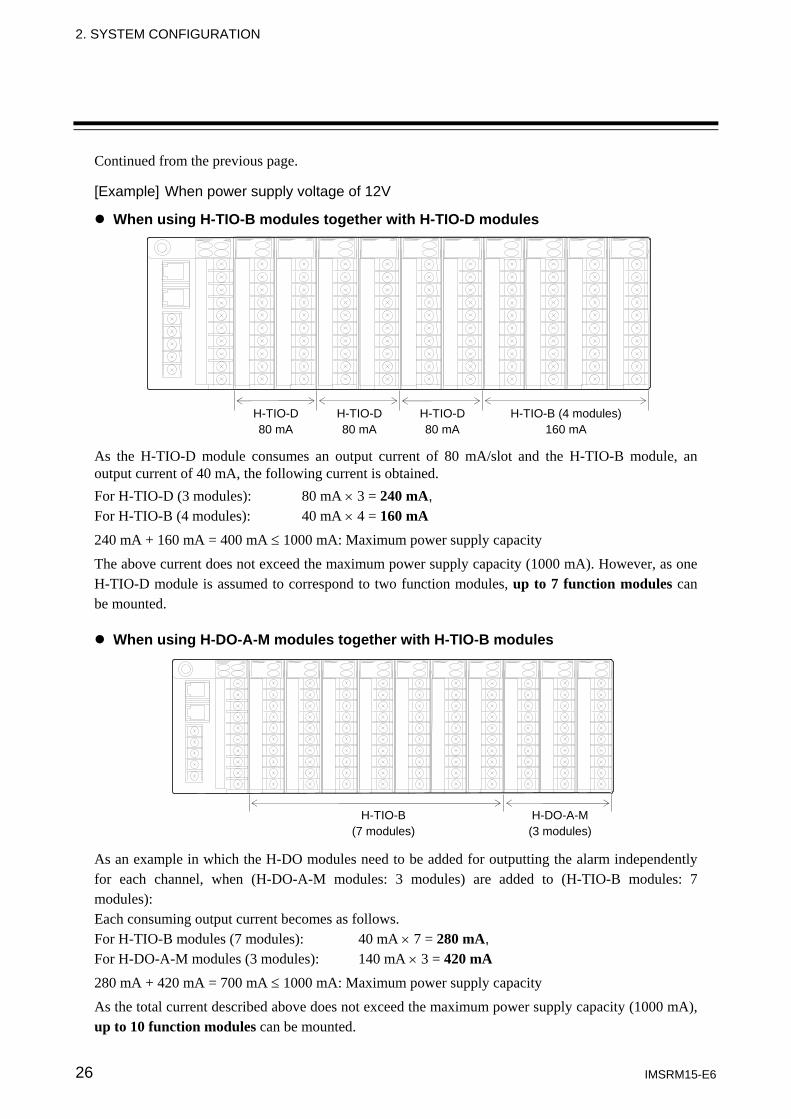
Continued from the previous page. [Example] When power supply voltage of 12V
When using H-TIO-B modules together with H-TIO-D modules As the H-TIO-D module consumes an output current of 80 mA/slot and the H-TIO-B module, an output current of 40 mA, the following current is obtained. For H-TIO-D (3 modules): 80 mA × 3 = 240 mA, For H-TIO-B (4 modules): 40 mA × 4 = 160 mA 240 mA + 160 mA = 400 mA ≤ 1000 mA: Maximum power supply capacity The above current does not exceed the maximum power supply capacity (1000 mA). However, as one H-TIO-D module is assumed to correspond to two function modules, up to 7 function modules can be mounted.
When using H-DO-A-M modules together with H-TIO-B modules As an example in which the H-DO modules need to be added for outputting the alarm independently for each channel, when (H-DO-A-M modules: 3 modules) are added to (H-TIO-B modules: 7 modules): Each consuming output current becomes as follows. For H-TIO-B modules (7 modules): 40 mA × 7 = 280 mA, For H-DO-A-M modules (3 modules): 140 mA × 3 = 420 mA 280 mA + 420 mA = 700 mA ≤ 1000 mA: Maximum power supply capacity As the total current described above does not exceed the maximum power supply capacity (1000 mA), up to 10 function modules can be mounted.
H-TIO-D 80 mA
H-TIO-D80 mA
H-TIO-D80 mA
H-TIO-B (4 modules) 160 mA
H-DO-A-M (3 modules)
H-TIO-B (7 modules)
2. SYSTEM CONFIGURATION
IMSRM15-E6 27
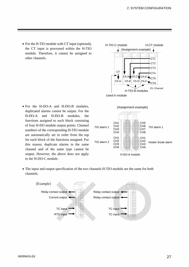
• For the H-TIO module with CT input (optional),
the CT input is processed within the H-TIO module. Therefore, it cannot be assigned to other channels.
• For the H-DO-A and H-DO-B modules,
duplicated alarms cannot be output. For the H-DO-A and H-DO-B modules, the functions assigned to each block consisting of four H-DO module output points. Channel numbers of the corresponding H-TIO module are automatically set in order from the top for each block of the functions assigned. For this reason, duplicate alarms in the same channel and of the same type cannot be output. However, the above does not apply to the H-DO-C module.
• The input and output specification of the two channels H-TIO module are the same for both
channels.
[Example]
CT1
CT2
CT3
CT4
CT5
CT6
CT
Ch.A
Ch.B
Ch.C
Ch.D Ch.E
Ch.F Ch.G
(Assignment example)
Used in module H-TIO-B modules
H-TIO-C module H-CT module
Ch: Channel
(Assignment example)
CH1CH2CH3CH4
CH1CH2CH3CH4
CH5 CH6 CH7 CH8
CH1 CH2 CH3 CH4
TIO alarm 1
TIO alarm 2
TIO alarm 1
Heater break alarm
H-DO-A module
Relay contact output
Relay contact output
TC input
TC input
Relay contact output
Current output
TC input
RTD input
28 IMSRM15-E6
3. DESCRIPTION OF EACH MODULES
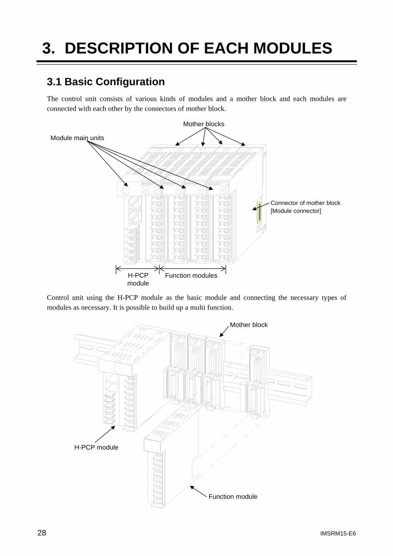
3.1 Basic Configuration The control unit consists of various kinds of modules and a mother block and each modules are connected with each other by the connectors of mother block.
Control unit using the H-PCP module as the basic module and connecting the necessary types of modules as necessary. It is possible to build up a multi function.
Mother block
H-PCP module
Function module
Mother blocks
Module main units
H-PCP module
Function modules
Connector of mother block [Module connector]
3. DESCRIPTION OF EACH MODULES
IMSRM15-E6 29
3.2 Common Item of Module 3.2.1 Mother block
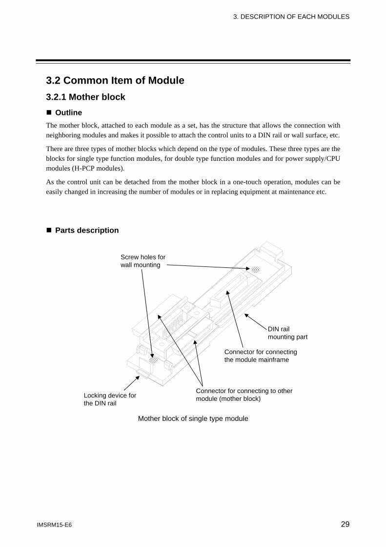
Outline The mother block, attached to each module as a set, has the structure that allows the connection with neighboring modules and makes it possible to attach the control units to a DIN rail or wall surface, etc.
There are three types of mother blocks which depend on the type of modules. These three types are the blocks for single type function modules, for double type function modules and for power supply/CPU modules (H-PCP modules).
As the control unit can be detached from the mother block in a one-touch operation, modules can be easily changed in increasing the number of modules or in replacing equipment at maintenance etc.
Parts description
Mother block of single type module
Screw holes for wall mounting
DIN rail mounting part
Connector for connecting the module mainframe
Connector for connecting to other module (mother block) Locking device for
the DIN rail
3. DESCRIPTION OF EACH MODULES
IMSRM15-E6 30
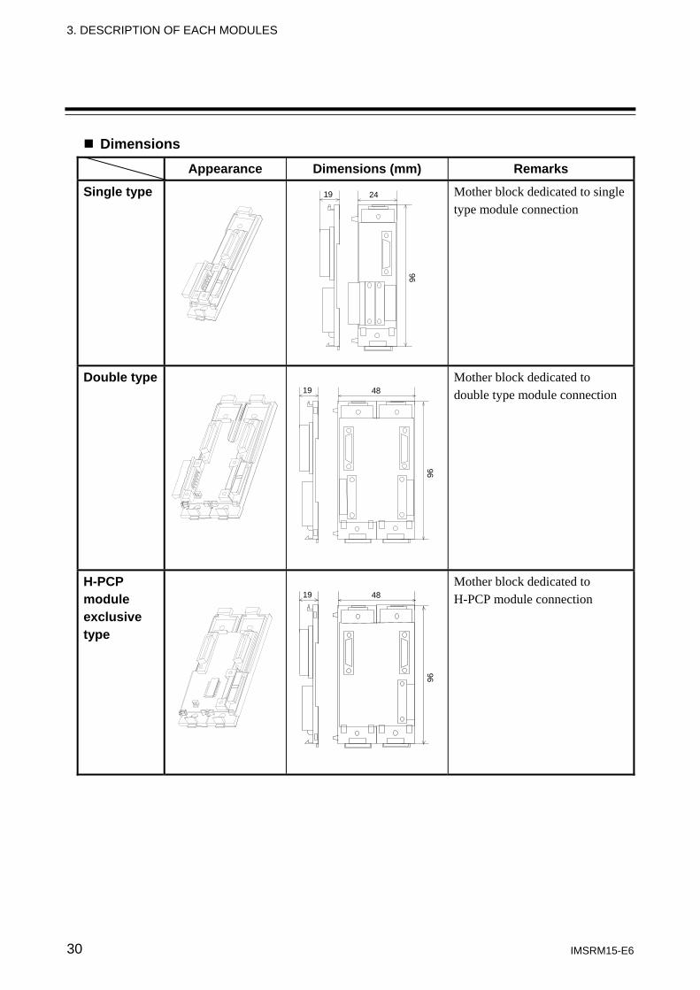
Dimensions Appearance Dimensions (mm) Remarks
Single type
19 24
96
Mother block dedicated to single type module connection
Double type
19 48
96
Mother block dedicated to double type module connection
H-PCP module exclusive type
19 48
96
Mother block dedicated to H-PCP module connection
3. DESCRIPTION OF EACH MODULES
IMSRM15-E6 31
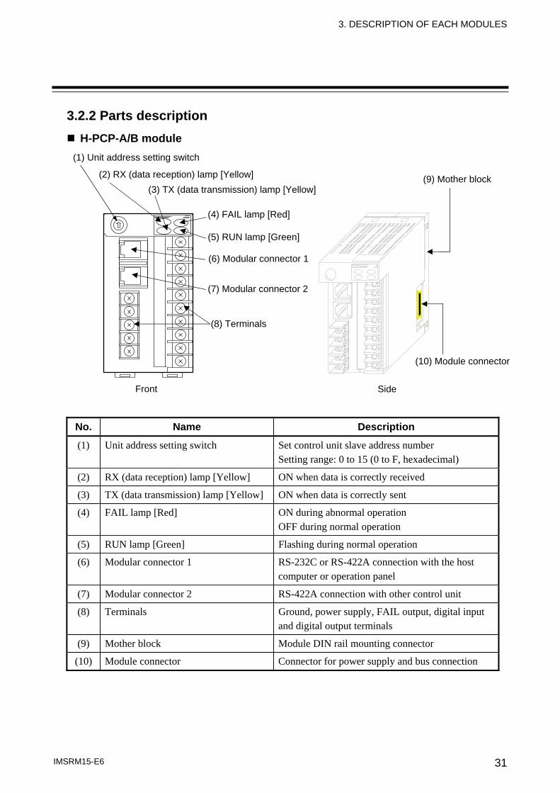
3.2.2 Parts description H-PCP-A/B module
No. Name Description
(1) Unit address setting switch Set control unit slave address number Setting range: 0 to 15 (0 to F, hexadecimal)
(2) RX (data reception) lamp [Yellow] ON when data is correctly received
(3) TX (data transmission) lamp [Yellow] ON when data is correctly sent
(4) FAIL lamp [Red] ON during abnormal operation OFF during normal operation
(5) RUN lamp [Green] Flashing during normal operation
(6) Modular connector 1 RS-232C or RS-422A connection with the host computer or operation panel
(7) Modular connector 2 RS-422A connection with other control unit
(8) Terminals Ground, power supply, FAIL output, digital input and digital output terminals
(9) Mother block Module DIN rail mounting connector
(10) Module connector Connector for power supply and bus connection
(10) Module connector
(9) Mother block
Side
(1) Unit address setting switch
(2) RX (data reception) lamp [Yellow]
(6) Modular connector 1
(8) Terminals
(7) Modular connector 2
(5) RUN lamp [Green]
(4) FAIL lamp [Red]
(3) TX (data transmission) lamp [Yellow]
Front
3. DESCRIPTION OF EACH MODULES
IMSRM15-E6 32
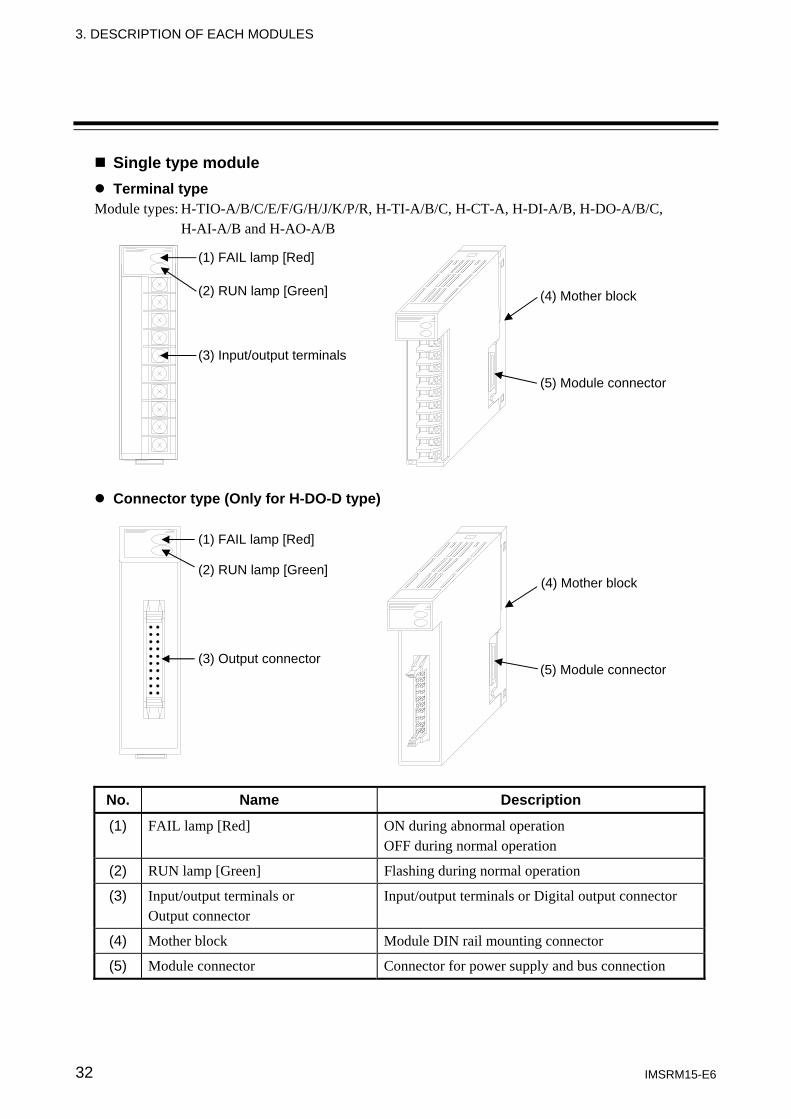
Single type module Terminal type
Module types: H-TIO-A/B/C/E/F/G/H/J/K/P/R, H-TI-A/B/C, H-CT-A, H-DI-A/B, H-DO-A/B/C, H-AI-A/B and H-AO-A/B
Connector type (Only for H-DO-D type)
No. Name Description
(1) FAIL lamp [Red] ON during abnormal operation OFF during normal operation
(2) RUN lamp [Green] Flashing during normal operation
(3) Input/output terminals or Output connector
Input/output terminals or Digital output connector
(4) Mother block Module DIN rail mounting connector
(5) Module connector Connector for power supply and bus connection
(5) Module connector
(4) Mother block
(1) FAIL lamp [Red]
(2) RUN lamp [Green]
(3) Input/output terminals
(5) Module connector
(4) Mother block
(1) FAIL lamp [Red]
(2) RUN lamp [Green]
(3) Output connector
3. DESCRIPTION OF EACH MODULES
IMSRM15-E6 33
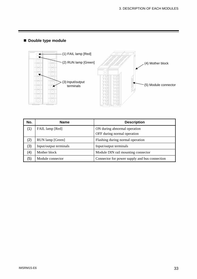
Double type module
No. Name Description
(1) FAIL lamp [Red] ON during abnormal operation OFF during normal operation
(2) RUN lamp [Green] Flashing during normal operation
(3) Input/output terminals Input/output terminals
(4) Mother block Module DIN rail mounting connector
(5) Module connector Connector for power supply and bus connection
(1) FAIL lamp [Red]
(2) RUN lamp [Green]
(5) Module connector
(4) Mother block
(3) Input/output terminals
3. DESCRIPTION OF EACH MODULES
IMSRM15-E6 34
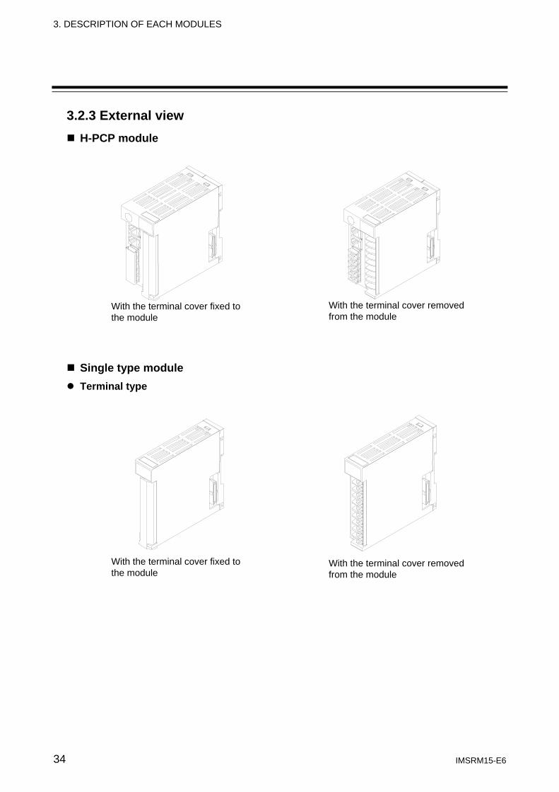
3.2.3 External view H-PCP module
Single type module Terminal type
With the terminal cover fixed to the module
With the terminal cover removed from the module
With the terminal cover fixed to the module
With the terminal cover removed from the module
3. DESCRIPTION OF EACH MODULES
IMSRM15-E6 35
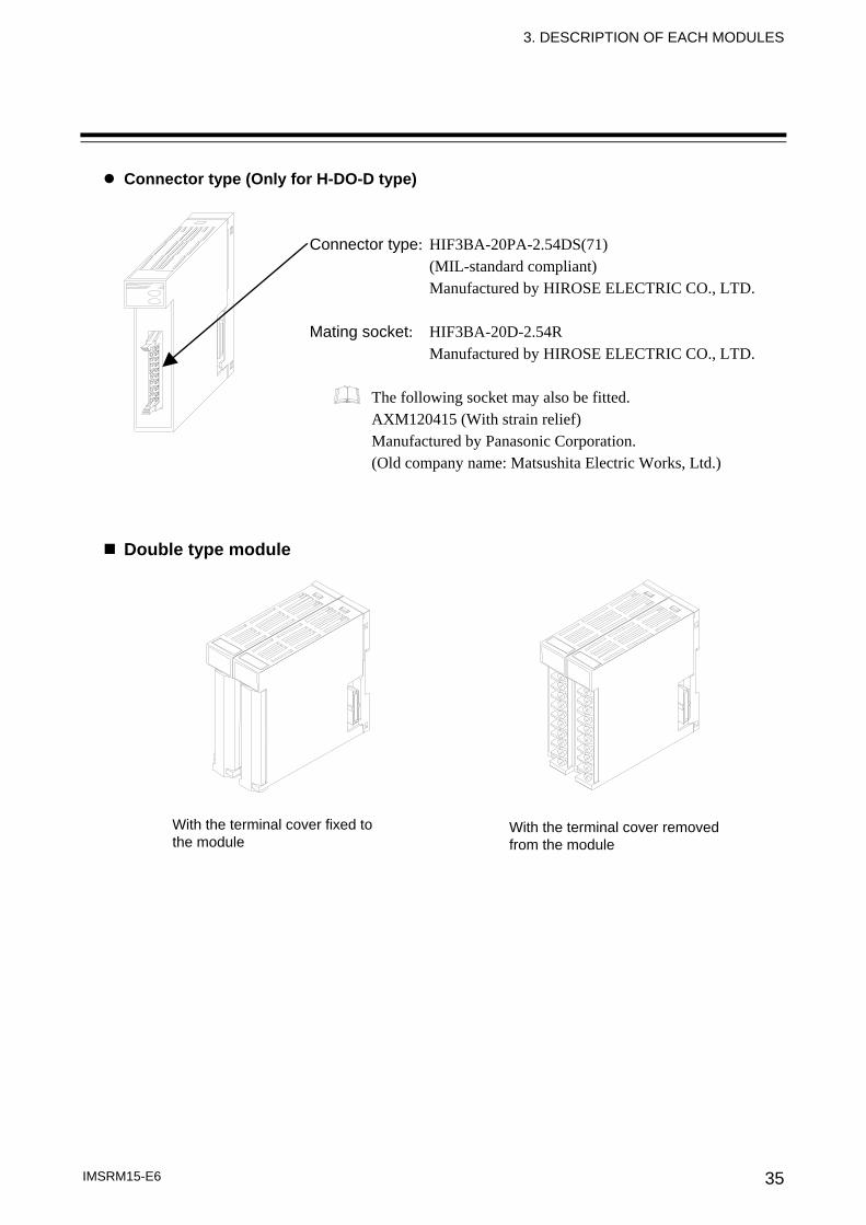
Connector type (Only for H-DO-D type)
Connector type: HIF3BA-20PA-2.54DS(71) (MIL-standard compliant) Manufactured by HIROSE ELECTRIC CO., LTD. Mating socket: HIF3BA-20D-2.54R Manufactured by HIROSE ELECTRIC CO., LTD.
The following socket may also be fitted. AXM120415 (With strain relief) Manufactured by Panasonic Corporation. (Old company name: Matsushita Electric Works, Ltd.)
Double type module
With the terminal cover fixed to the module
With the terminal cover removed from the module
3. DESCRIPTION OF EACH MODULES
IMSRM15-E6 36
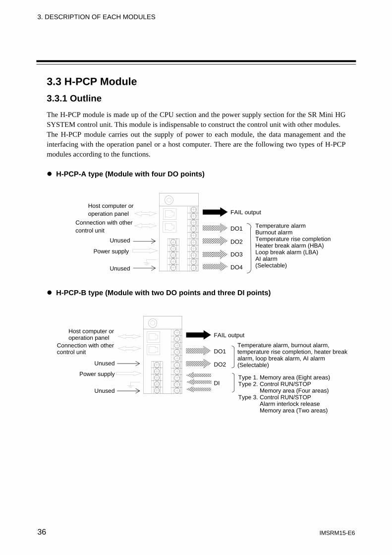
3.3 H-PCP Module 3.3.1 Outline The H-PCP module is made up of the CPU section and the power supply section for the SR Mini HG SYSTEM control unit. This module is indispensable to construct the control unit with other modules. The H-PCP module carries out the supply of power to each module, the data management and the interfacing with the operation panel or a host computer. There are the following two types of H-PCP modules according to the functions.
H-PCP-A type (Module with four DO points)
H-PCP-B type (Module with two DO points and three DI points)
FAIL output
DO1
DO2
DO3
DO4
Power supply
Unused
Host computer or operation panel
Connection with other control unit
Temperature alarm Burnout alarm Temperature rise completionHeater break alarm (HBA) Loop break alarm (LBA) AI alarm (Selectable) Unused
FAIL output
DO1
DO2
DI
Temperature alarm, burnout alarm, temperature rise completion, heater break alarm, loop break alarm, AI alarm (Selectable)
Type 1. Memory area (Eight areas)Type 2. Control RUN/STOP
Memory area (Four areas) Type 3. Control RUN/STOP
Alarm interlock release Memory area (Two areas)
Power supply
Unused
Host computer or operation panel
Connection with other control unit
Unused
3. DESCRIPTION OF EACH MODULES
IMSRM15-E6 37
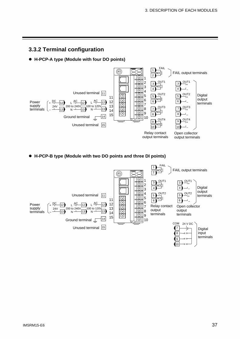
3.3.2 Terminal configuration H-PCP-A type (Module with four DO points)
H-PCP-B type (Module with two DO points and three DI points)
FAIL
OUT1
NO
NO
NO
1
2
3
OUT2
4
5
61112131415
12345678910
OUT1 3
OUT2
4
5
6
+
-
+
- DC
24V +
-
12
13
FAIL output terminals
Open collector output terminals
Relay contact output terminals
Power supply terminals
Digital output terminals
AC
200 to 240V L
N
12
13
AC
100 to 120VL
N
12
13
11Unused terminal
14
15Unused terminal
Ground terminal COM 24 V DC
7
8
9
10
Digital input terminals
FAIL
OUT1
NO
NO
NO
1
2
3
OUT2
4
5
61112131415
12345678910
OUT3
NO
NO
7
OUT4
8
9
OUT1 3
OUT2
4
5
6
OUT3 7
OUT4
8
9
+
-
+
-
+
-
+
-
10 10
DC
24V +
-
12
13
FAIL output terminals
Open collector output terminals
Relay contact output terminals
Power supply terminals
Digital output terminals
AC
200 to 240V L
N
12
13
AC
100 to 120VL
N
12
13
11Unused terminal
14
15
Ground terminal
Unused terminal
3. DESCRIPTION OF EACH MODULES
IMSRM15-E6 38
3.3.3 Functional description Output function FAIL output
The FAIL output is output when a problem occurs in the CPU operation and the FAIL lamp will light at the same time. Use this output for FAIL monitoring or for signal output to an external PLC, etc. • Number of outputs: 1 point • Output type: Relay contact output, 1a contact (Open at error occurrence)
[Rating: 250 V AC, 0.1 A (Resistive load)] (CE/UL/cUL (or CSA) approved instrument: 30 V DC, 0.1 A)
When the FAIL condition occurs in any of the function modules in the control unit, the FAIL output will also be output. However in this situation, the FAIL lamp will not light. If the composition of the control unit is changed (add or delete a function module, or change the arrangement of the modules, or replace a module with a different model) without the module initialization, the FAIL output will be output. However in this situation the FAIL lamp will not light either. For details on how to initialize the module, refer to SR Mini/SR Mini HG SYSTEM Supplementary Information Initialize Settings [Extended Communications] (IMSRM07-E ).
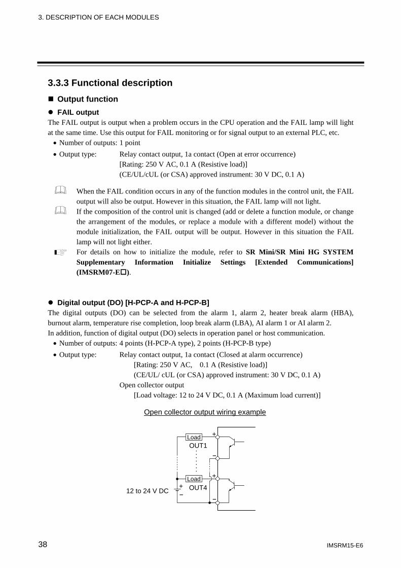
Digital output (DO) [H-PCP-A and H-PCP-B] The digital outputs (DO) can be selected from the alarm 1, alarm 2, heater break alarm (HBA), burnout alarm, temperature rise completion, loop break alarm (LBA), AI alarm 1 or AI alarm 2. In addition, function of digital output (DO) selects in operation panel or host communication. • Number of outputs: 4 points (H-PCP-A type), 2 points (H-PCP-B type) • Output type: Relay contact output, 1a contact (Closed at alarm occurrence)
[Rating: 250 V AC, 0.1 A (Resistive load)] (CE/UL/ cUL (or CSA) approved instrument: 30 V DC, 0.1 A) Open collector output [Load voltage: 12 to 24 V DC, 0.1 A (Maximum load current)]
Open collector output wiring example
12 to 24 V DC OUT4
OUT1
++
+
- -
-⋅⋅⋅⋅⋅⋅⋅
Load
Load
3. DESCRIPTION OF EACH MODULES
IMSRM15-E6 39
If there is no heater break alarm function in the control unit (H-TIO-A/C/D modules provided with CT input as optional, or control unit without H-CT module), a heater break alarm cannot be selected. If there is no H-AI module in the control unit, an AI alarm cannot be selected. For the control unit consisting of only the H-TIO-H/J modules, a loop break alarm cannot be selected. For details on function selection with the digital output, refer to SR Mini/SR Mini HG SYSTEM Supplementary Information Initialize Settings [Extended Communications] (IMSRM07-E ).
Input function Digital input (DI) [H-PCP-B]
For digital input, memory area selection, control RUN/STOP selection or alarm interlock release specifying can be performed. In addition, any of the following combinations of functions is available for digital input. • Type 1: Memory area selection (8 areas selection) • Type 2: Combination of control RUN/STOP selection and memory area selection (4 areas selection) • Type 3: Combination of control RUN/STOP selection, alarm interlock release and memory area selection (2 areas selection)
After the contact is closed, it takes a short time until the action of this device is actually selected. Therefore, pay attention to this delay time if the device is used together with a PLC, etc. External power (24 V DC) supply is required for digital input.
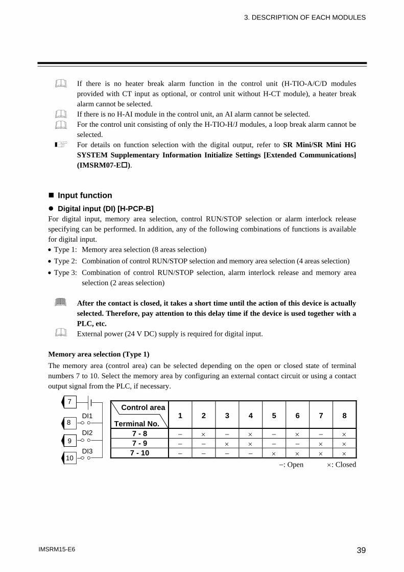
Memory area selection (Type 1) The memory area (control area) can be selected depending on the open or closed state of terminal numbers 7 to 10. Select the memory area by configuring an external contact circuit or using a contact output signal from the PLC, if necessary.
Control area
Terminal No. 1 2 3 4 5 6 7 8
7 - 8 − × − × − × − ×7 - 9 − − × × − − × ×
7 - 10 − − − − × × × ×−: Open ×: Closed
7
8
9
10
DI1
DI2
DI3
3. DESCRIPTION OF EACH MODULES
IMSRM15-E6 40
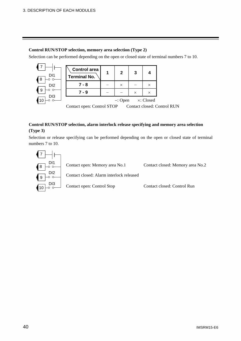
Control RUN/STOP selection, memory area selection (Type 2) Selection can be performed depending on the open or closed state of terminal numbers 7 to 10.
Control area Terminal No.
1 2 3 4
7 - 8 − × − ×
7 - 9 − − × ×
−: Open ×: Closed Contact open: Control STOP Contact closed: Control RUN
Control RUN/STOP selection, alarm interlock release specifying and memory area selection (Type 3) Selection or release specifying can be performed depending on the open or closed state of terminal numbers 7 to 10.
Contact open: Memory area No.1 Contact closed: Memory area No.2
Contact closed: Alarm interlock released
Contact open: Control Stop Contact closed: Control Run
7
8
9
10
DI1
DI2
DI3
7
8
9
10
DI1
DI2
DI3
3. DESCRIPTION OF EACH MODULES
IMSRM15-E6 41
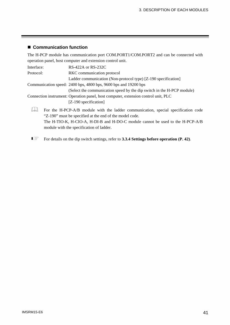
Communication function The H-PCP module has communication port COM.PORT1/COM.PORT2 and can be connected with operation panel, host computer and extension control unit. Interface: RS-422A or RS-232C Protocol: RKC communication protocol
Ladder communication (Non-protocol type) [Z-190 specification] Communication speed: 2400 bps, 4800 bps, 9600 bps and 19200 bps
(Select the communication speed by the dip switch in the H-PCP module) Connection instrument: Operation panel, host computer, extension control unit, PLC
[Z-190 specification]
For the H-PCP-A/B module with the ladder communication, special specification code “Z-190” must be specified at the end of the model code. The H-TIO-K, H-CIO-A, H-DI-B and H-DO-C module cannot be used to the H-PCP-A/B module with the specification of ladder.
For details on the dip switch settings, refer to 3.3.4 Settings before operation (P. 42).
3. DESCRIPTION OF EACH MODULES
IMSRM15-E6 42
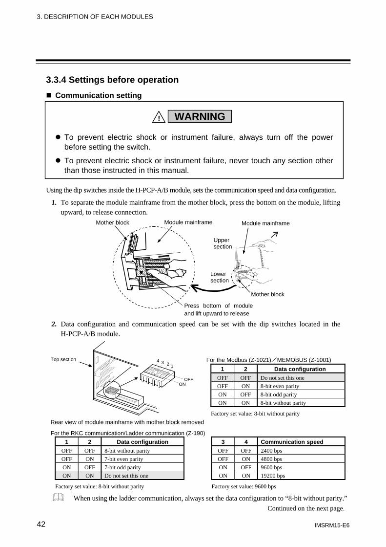
3.3.4 Settings before operation Communication setting
Using the dip switches inside the H-PCP-A/B module, sets the communication speed and data configuration.
1. To separate the module mainframe from the mother block, press the bottom on the module, lifting upward, to release connection.
2. Data configuration and communication speed can be set with the dip switches located in the H-PCP-A/B module.
Top section
OFFON
4 3 2 1
Rear view of module mainframe with mother block removed For the RKC communication/Ladder communication (Z-190)
1 2 Data configuration 3 4 Communication speed OFF OFF 8-bit without parity OFF OFF 2400 bps OFF ON 7-bit even parity OFF ON 4800 bps ON OFF 7-bit odd parity ON OFF 9600 bps ON ON Do not set this one ON ON 19200 bps
Factory set value: 8-bit without parity Factory set value: 9600 bps
When using the ladder communication, always set the data configuration to “8-bit without parity.”
For the Modbus (Z-1021)/MEMOBUS (Z-1001) 1 2 Data configuration
OFF OFF Do not set this one OFF ON 8-bit even parity ON OFF 8-bit odd parity ON ON 8-bit without parity
Factory set value: 8-bit without parity
To prevent electric shock or instrument failure, always turn off the power before setting the switch.
To prevent electric shock or instrument failure, never touch any section other than those instructed in this manual.
WARNING!
Continued on the next page.
Mother block Module mainframe
Upper section
Mother block
Module mainframe
Lower section
Press bottom of module and lift upward to release
3. DESCRIPTION OF EACH MODULES
IMSRM15-E6 43
3. After communication setting is complete, place the module mainframe opening on top of the mother block tab and snap the lower part of module mainframe on to the mother block. A snapping sound will be heard when module mainframe is securely connected to mother block.
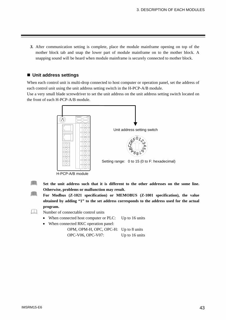
Unit address settings When each control unit is multi-drop connected to host computer or operation panel, set the address of each control unit using the unit address setting switch in the H-PCP-A/B module. Use a very small blade screwdriver to set the unit address on the unit address setting switch located on the front of each H-PCP-A/B module.
876543
210FEDC B A9
H-PCP-A/B module
Setting range: 0 to 15 (0 to F: hexadecimal)
Unit address setting switch
Set the unit address such that it is different to the other addresses on the some line. Otherwise, problems or malfunction may result. For Modbus (Z-1021 specification) or MEMOBUS (Z-1001 specification), the value obtained by adding “1” to the set address corresponds to the address used for the actual program. Number of connectable control units • When connected host computer or PLC: Up to 16 units • When connected RKC operation panel:
OPM, OPM-H, OPC, OPC-H: Up to 8 units OPC-V06, OPC-V07: Up to 16 units
3. DESCRIPTION OF EACH MODULES
IMSRM15-E6 44
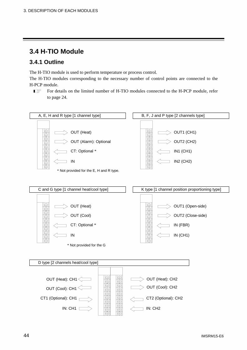
3.4 H-TIO Module 3.4.1 Outline The H-TIO module is used to perform temperature or process control. The H-TIO modules corresponding to the necessary number of control points are connected to the H-PCP module.
For details on the limited number of H-TIO modules connected to the H-PCP module, refer to page 24.
A, E, H and R type [1 channel type]
OUT (Heat)
OUT (Alarm): Optional
CT: Optional *
IN
* Not provided for the E, H and R type.
B, F, J and P type [2 channels type]
OUT1 (CH1)
OUT2 (CH2)
IN1 (CH1)
IN2 (CH2)
C and G type [1 channel heat/cool type]
OUT (Heat)
OUT (Cool)
CT: Optional *
IN
* Not provided for the G
K type [1 channel position proportioning type]
OUT1 (Open-side)
OUT2 (Close-side)
IN (FBR)
IN (CH1)
D type [2 channels heat/cool type]
OUT (Heat): CH1
OUT (Cool): CH1
CT1 (Optional): CH1
IN: CH1
OUT (Heat): CH2
OUT (Cool): CH2
CT2 (Optional): CH2
IN: CH2
3. DESCRIPTION OF EACH MODULES
IMSRM15-E6 45
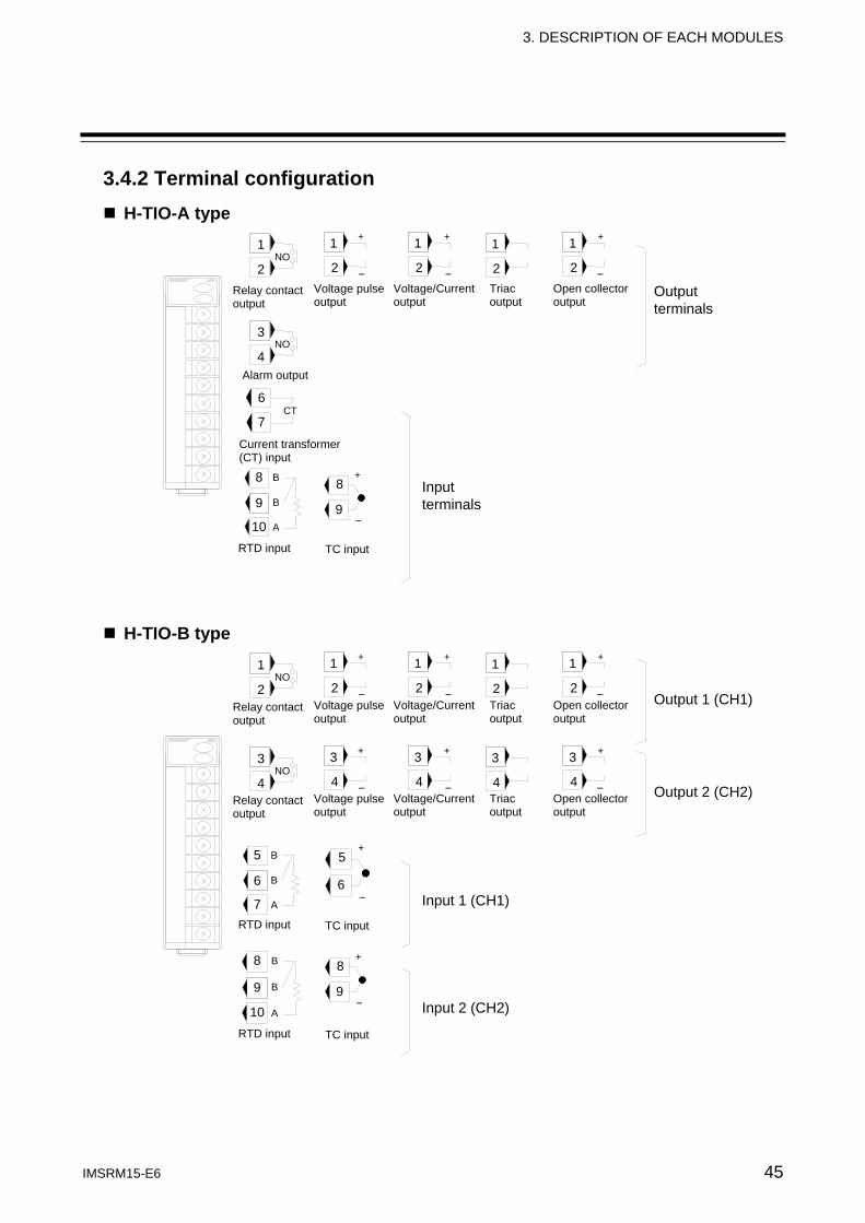
3.4.2 Terminal configuration H-TIO-A type
H-TIO-B type
Open collector output
Output terminals
Relay contact output
Voltage pulseoutput
Voltage/Currentoutput
Triac output
Alarm output
Current transformer (CT) input
RTD input TC input
Input terminals
1
2
3
4
1
2NO
NO
8
9
10
B
B
A
8
9
+
−
1
2
+
−
1
2
+
−
1
2
+
−
1
2
1
2NO
1
2
+
−
1
2
+
−
1
2
+
−
3
4
3
4NO
3
4
+
−
3
4
+
−
3
4
+
−
Output 1 (CH1)
Output 2 (CH2)
5
6
7
B
B
A
5
6
+
−
8
9
10
B
B
A
8
9
+
−
Input 1 (CH1)
Input 2 (CH2)
Open collector output
Relay contact output
Voltage pulseoutput
Voltage/Currentoutput
Triac output
Open collector output
Relay contact output
Voltage pulseoutput
Voltage/Currentoutput
Triac output
RTD input TC input
RTD input TC input
6
7CT
3. DESCRIPTION OF EACH MODULES
IMSRM15-E6 46
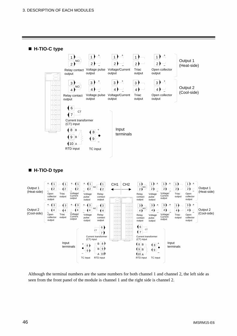
H-TIO-C type
H-TIO-D type Although the terminal numbers are the same numbers for both channel 1 and channel 2, the left side as seen from the front panel of the module is channel 1 and the right side is channel 2.
1
2
1
2NO
1
2
+
−
1
2
+
−
1
2
+
−
3
4
3
4NO
3
4
+
−
3
4
+
−
3
4
+
−
Output 1 (Heat-side)
Input terminals
8
9
10
B
B
A
8
9
+
−
Output 2 (Cool-side)
1
2
1
2NO
1
2
+
−
1
2
+
−
1
2
+
−
3
4
3
4NO
3
4
+
−
3
4
+
−
3
4
+
−
Output 1 (Heat-side)
Current transformer (CT) input
RTD input TC input
Input terminals
6
7CT
8
9
10
B
B
A
8
9
+
−
Output 2 (Cool-side)
6
7CT
8
9
10
B
B
A
8
9
+
−
CH1 CH2
Open collector output
Relay contact output
Voltage pulseoutput
Voltage/Currentoutput
Triac output
Open collector output
Relay contact output
Voltage pulseoutput
Voltage/Currentoutput
Triac output
Current transformer (CT) input
RTD input TC input
Open collector output
Relay contactoutput
Voltage pulse output
Voltage/ Current output
Triac output
Open collector output
Relay contactoutput
Voltage pulse output
Voltage/ Current output
Triac output
Open collector output
Relay contactoutput
Voltage pulse output
Voltage/ Current output
Triac output
1
2
1
2NO
1
2
+
−
1
2
+
−
1
2
+
−
3
4
3
4NO
3
4
+
−
3
4
+
−
3
4
+
−Open collector output
Relay contactoutput
Voltage pulse output
Voltage/ Current output
Triac output
Output 1 (Heat-side)
Output 2 (Cool-side)
Current transformer (CT) input
RTD input TC input
Input terminals
6
7CT
3. DESCRIPTION OF EACH MODULES
IMSRM15-E6 47
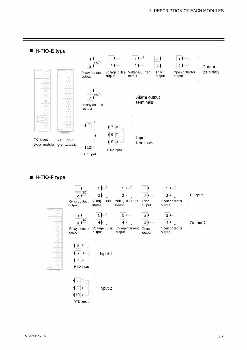
H-TIO-E type
H-TIO-F type
1
2
1
2 NO
1
2
+
−
1
2
+
−
1
2
+
−
3
4
3
4 NO
3
4
+
−
3
4
+
−
3
4
+
−
Output 1
RTD input
Input 1
5
6
7
B
B
A
Output 2
RTD input
8
9
10
B
B
A
Input 2
Output terminals
Alarm output terminals
RTD inputTC input
Input terminals
1
2
1
2 NO
3
4 NO
7
8
9
B
B
A
7
10
+
−
1
2
+
−
1
2
+
−
1
2
+
−
RTD input type module
TC input type module
Open collector output
Relay contact output
Voltage pulseoutput
Voltage/Currentoutput
Triac output
Relay contactoutput
Open collector output
Relay contact output
Voltage pulseoutput
Voltage/Currentoutput
Triac output
Open collector output
Relay contact output
Voltage pulseoutput
Voltage/Currentoutput
Triac output
3. DESCRIPTION OF EACH MODULES
IMSRM15-E6 48
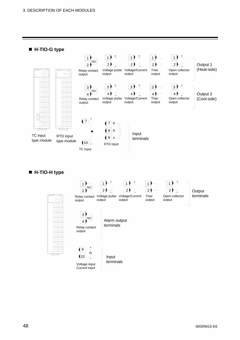
H-TIO-G type
H-TIO-H type
Output 1 (Heat-side)
1
2
1
2 NO
7
8
9
B
B
A
7
10
+
−
1
2
+
−
1
2
+
−
1
2
+
−
RTD input type module
TC input type module
Output 2 (Cool-side)
3
4
3
4 NO
3
4
+
−
3
4
+
−
3
4
+
−
1
2
1
2 NO
3
4 NO
1
2
+
−
1
2
+
−
1
2
+
−
Voltage input Current input
9
10 IN
+
−
Open collector output
Relay contact output
Voltage pulseoutput
Voltage/Currentoutput
Triac output
Open collector output
Relay contact output
Voltage pulseoutput
Voltage/Currentoutput
Triac output
RTD inputTC input
Input terminals
Open collector output
Relay contact output
Voltage pulseoutput
Voltage/Currentoutput
Triac output
Relay contact output
Output terminals
Alarm output terminals
Input terminals
3. DESCRIPTION OF EACH MODULES
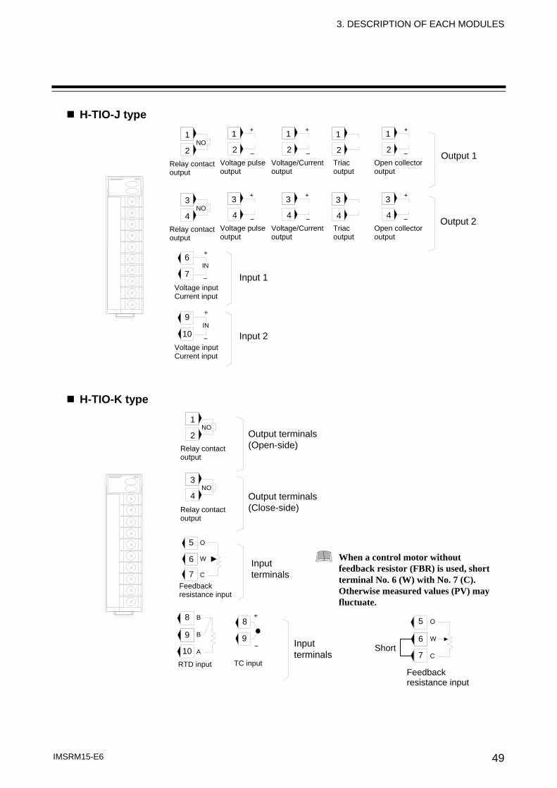
IMSRM15-E6 49
H-TIO-J type
H-TIO-K type
Output 1
1
2
1
2 NO
1
2
+
−
1
2
+
−
1
2
+
−
Output 2
3
4
3
4 NO
3
4
+
−
3
4
+
−
3
4
+
−
Input 1
6
7 IN
+
−
Input 2
9
10 IN
+
−
Open collector output
Relay contact output
Voltage pulseoutput
Voltage/Currentoutput
Triac output
Open collector output
Relay contact output
Voltage pulseoutput
Voltage/Currentoutput
Triac output
Voltage input Current input
Voltage input Current input
1
2 NO
3
4 NO
Output terminals (Open-side)
Feedback resistance input
5
6
7
O
W
C
RTD input TC input
8
9
10
B
B
A
8
9
+
−
Input terminals
Relay contact output
Relay contact output
Output terminals (Close-side)
Input terminals
When a control motor without feedback resistor (FBR) is used, short terminal No. 6 (W) with No. 7 (C). Otherwise measured values (PV) may fluctuate.
5
6
7
O
W
C
Feedback resistance input
Short
3. DESCRIPTION OF EACH MODULES
IMSRM15-E6 50
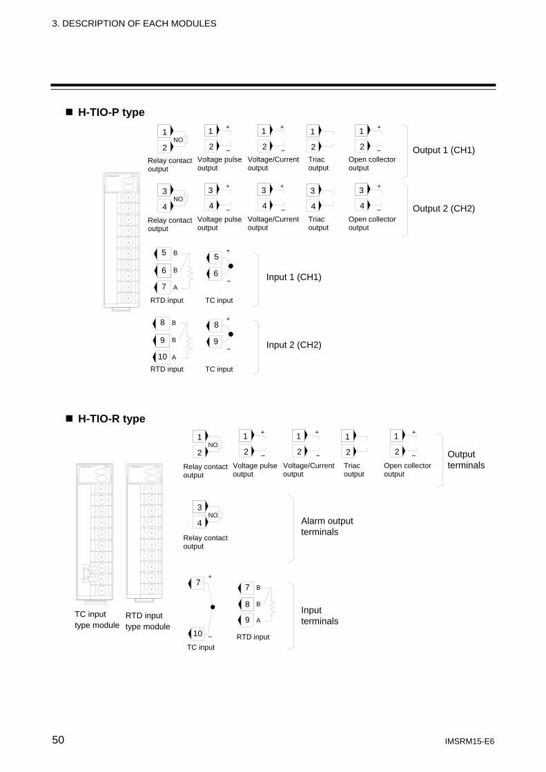
H-TIO-P type
H-TIO-R type
1
2
1
2NO
1
2
+
−
1
2
+
−
1
2
+
−
3
4
3
4NO
3
4
+
−
3
4
+
−
3
4
+
−
Output 1 (CH1)
Output 2 (CH2)
5
6
7
B
B
A
5
6
+
−
8
9
10
B
B
A
8
9
+
−
Input 1 (CH1)
Input 2 (CH2)
Output terminals
Alarm output terminals
RTD inputTC input
Input terminals
1
2
1
2 NO
3
4 NO
7
8
9
B
B
A
7
10
+
−
1
2
+
−
1
2
+
−
1
2
+
−
RTD input type module
TC input type module
Open collector output
Relay contactoutput
Voltage pulseoutput
Voltage/Currentoutput
Triac output
Relay contactoutput
Open collector output
Relay contact output
Voltage pulseoutput
Voltage/Currentoutput
Triac output
Open collector output
Relay contact output
Voltage pulseoutput
Voltage/Currentoutput
Triac output
RTD input TC input
RTD input TC input
3. DESCRIPTION OF EACH MODULES
IMSRM15-E6 51
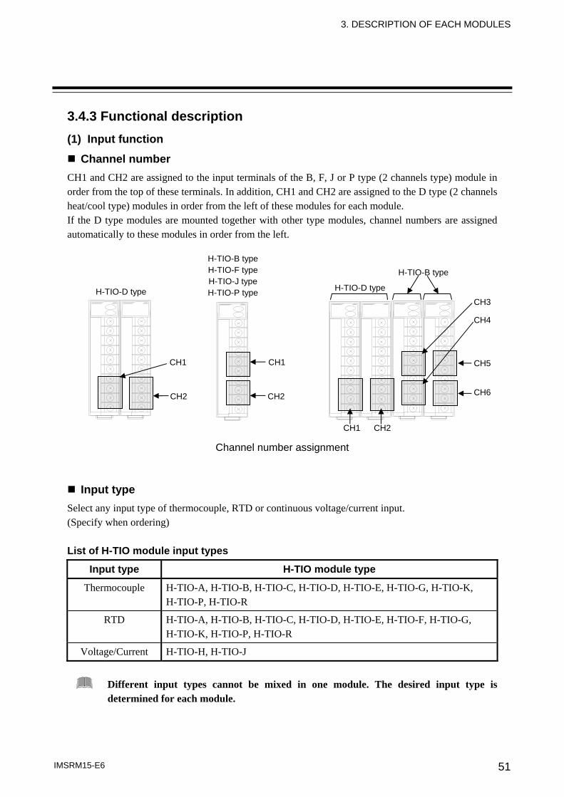
3.4.3 Functional description (1) Input function
Channel number CH1 and CH2 are assigned to the input terminals of the B, F, J or P type (2 channels type) module in order from the top of these terminals. In addition, CH1 and CH2 are assigned to the D type (2 channels heat/cool type) modules in order from the left of these modules for each module. If the D type modules are mounted together with other type modules, channel numbers are assigned automatically to these modules in order from the left.
Channel number assignment
Input type Select any input type of thermocouple, RTD or continuous voltage/current input. (Specify when ordering) List of H-TIO module input types
Input type H-TIO module type
Thermocouple H-TIO-A, H-TIO-B, H-TIO-C, H-TIO-D, H-TIO-E, H-TIO-G, H-TIO-K, H-TIO-P, H-TIO-R
RTD H-TIO-A, H-TIO-B, H-TIO-C, H-TIO-D, H-TIO-E, H-TIO-F, H-TIO-G, H-TIO-K, H-TIO-P, H-TIO-R
Voltage/Current H-TIO-H, H-TIO-J
Different input types cannot be mixed in one module. The desired input type is determined for each module.
H-TIO-D type
H-TIO-B typeH-TIO-F typeH-TIO-J typeH-TIO-P type H-TIO-D type
H-TIO-B type
CH2
CH1
CH2
CH1
CH1 CH2
CH3
CH4
CH5
CH6
3. DESCRIPTION OF EACH MODULES
IMSRM15-E6 52
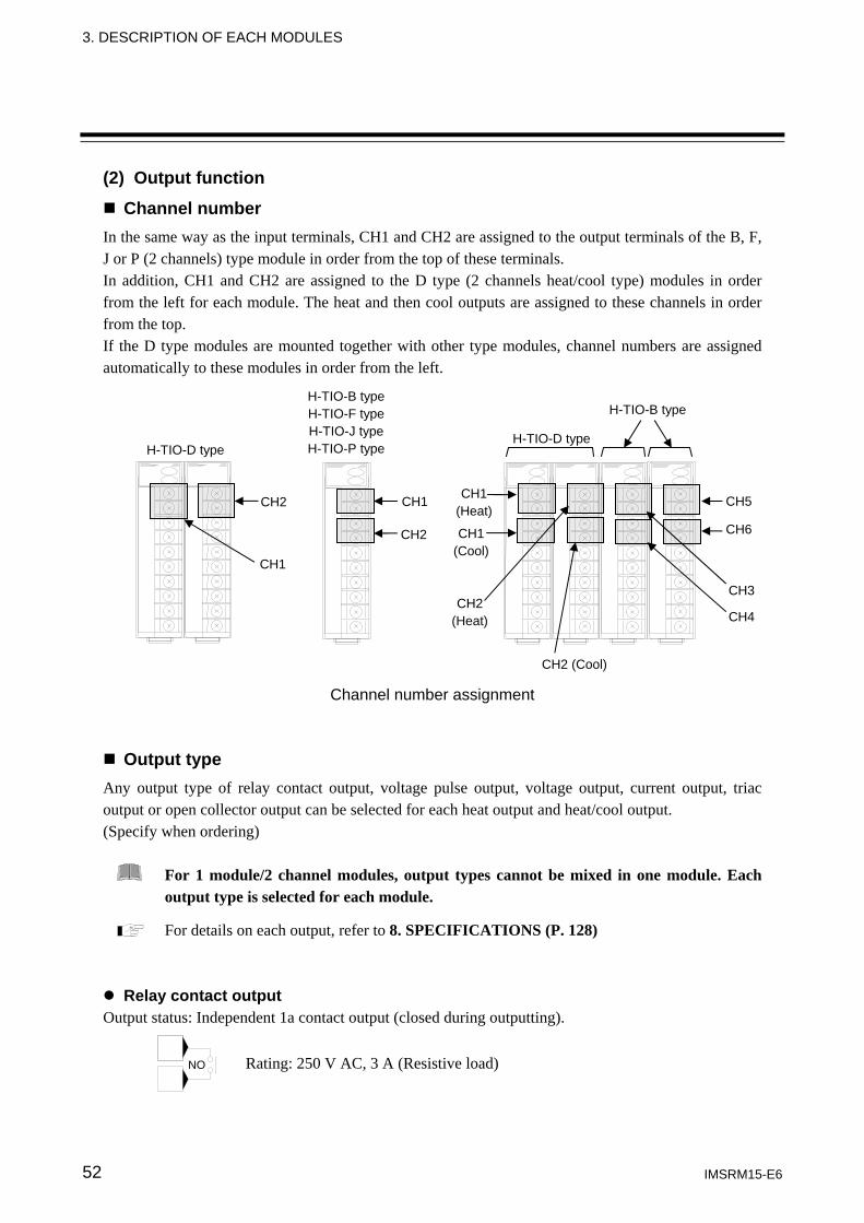
(2) Output function
Channel number In the same way as the input terminals, CH1 and CH2 are assigned to the output terminals of the B, F, J or P (2 channels) type module in order from the top of these terminals. In addition, CH1 and CH2 are assigned to the D type (2 channels heat/cool type) modules in order from the left for each module. The heat and then cool outputs are assigned to these channels in order from the top. If the D type modules are mounted together with other type modules, channel numbers are assigned automatically to these modules in order from the left.
Channel number assignment
Output type Any output type of relay contact output, voltage pulse output, voltage output, current output, triac output or open collector output can be selected for each heat output and heat/cool output. (Specify when ordering)
For 1 module/2 channel modules, output types cannot be mixed in one module. Each output type is selected for each module.
For details on each output, refer to 8. SPECIFICATIONS (P. 128)
Relay contact output Output status: Independent 1a contact output (closed during outputting).
CH1
CH2 (Cool)
CH3
CH4
H-TIO-D type
H-TIO-B typeH-TIO-F typeH-TIO-J typeH-TIO-P type
H-TIO-D type
H-TIO-B type
CH2
CH2
CH1 CH1(Heat)
CH5
CH6CH1(Cool)
CH2(Heat)
NO Rating: 250 V AC, 3 A (Resistive load)
3. DESCRIPTION OF EACH MODULES
IMSRM15-E6 53
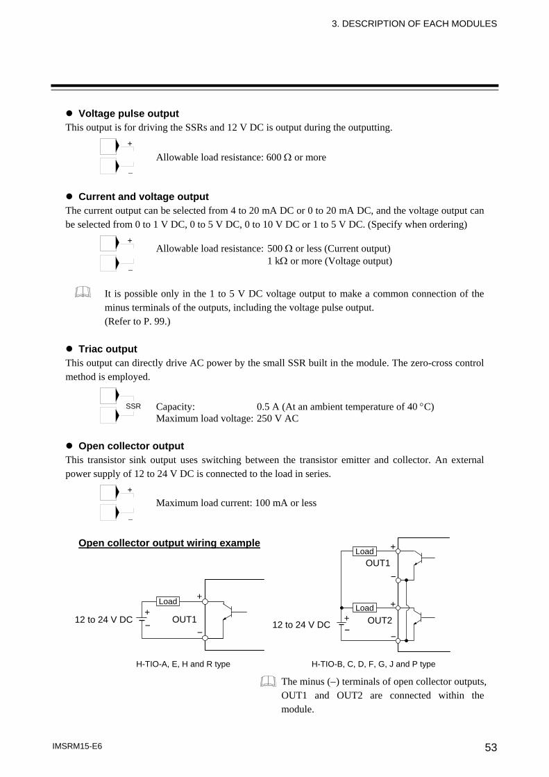
Voltage pulse output This output is for driving the SSRs and 12 V DC is output during the outputting.
Current and voltage output The current output can be selected from 4 to 20 mA DC or 0 to 20 mA DC, and the voltage output can be selected from 0 to 1 V DC, 0 to 5 V DC, 0 to 10 V DC or 1 to 5 V DC. (Specify when ordering)
It is possible only in the 1 to 5 V DC voltage output to make a common connection of the minus terminals of the outputs, including the voltage pulse output. (Refer to P. 99.)
Triac output
This output can directly drive AC power by the small SSR built in the module. The zero-cross control method is employed.
Open collector output This transistor sink output uses switching between the transistor emitter and collector. An external power supply of 12 to 24 V DC is connected to the load in series.
Open collector output wiring example
The minus (−) terminals of open collector outputs, OUT1 and OUT2 are connected within the module.
+
−
+
−
+
−
Allowable load resistance: 600 Ω or more
Allowable load resistance: 500 Ω or less (Current output) 1 kΩ or more (Voltage output)
Capacity: 0.5 A (At an ambient temperature of 40 °C) Maximum load voltage: 250 V AC
Maximum load current: 100 mA or less
12 to 24 V DC OUT1 +
+
- -
H-TIO-A, E, H and R type
12 to 24 V DC OUT2
OUT1
++
+
--
-
H-TIO-B, C, D, F, G, J and P type
Load
Load Load
SSR
3. DESCRIPTION OF EACH MODULES
IMSRM15-E6 54
(3) Alarm function
One H-TIO module is provided with two alarm points (Alarm 1 and Alarm 2) as standard. Alarm 1/2 types are those selected by the H-PCP module.
Alarm type: Deviation high alarm Process high alarm Deviation low alarm Process low alarm Deviation high and low alarm Process high alarm with hold action Band alarm Process low alarm with hold action Deviation high alarm with hold action Deviation high alarm with re-hold action Deviation low alarm with hold action Deviation low alarm with re-hold action Deviation high and low alarm with hold action Deviation high and low alarm with re-hold action
(4) Alarm output function (Optional)
An alarm can be output from the H-TIO module itself (only for the H-TIO-A/E/H/R types). • Number of output points: 1 point (relay contact output) • Output type : Select any of temperature alarm output (ALM1), temperature alarm output (ALM2),
heater break alarm output (HBA) 1 or loop break alarm output (LBA) 2. (The output type needs to be specified in the model code at the time of ordering.)
1 Only H-TIO-A can be selected. 2 Only H-TIO-A, H-TIO-E or H-TIO-R can be selected.
Each alarm can be output as summary output (OR output) from the digital output block in the H-PCP-A/B module. For details, refer to 3.3 H-PCP Module (P. 36).
The respective alarm (Alarm 1/2) can be output independently for each channel by connecting the H-DO-A/B/D module. For details, refer to 3.9 H-DO Module (P. 70).
For H-TIO-A/E/H/R type modules, an alarm can be output from each module (optional). (5) Loop break alarm function (Excluding H-TIO-H/J type modules)
The loop break alarm function is used to detect a load (heater) break, a failure occurring in any external operating device (magnet relay, etc.) or a failure occurring in the control system (control loop) caused by an input (sensor) break. (Refer to P. 124.)
The loop break alarm can be output as summary output (OR output) from the digital output block in the H-PCP-A/B module. For details, refer to 3.3 H-PCP Module (P. 36).
The loop break alarm can be output independently for each channel by connecting the H-DO-A/B/D module. For details, refer to 3.9 H-DO Module (P. 70).
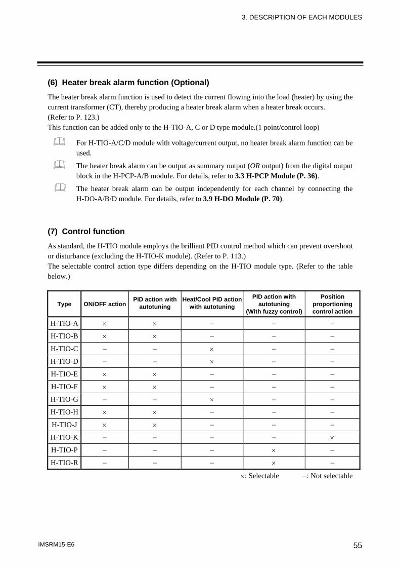
3. DESCRIPTION OF EACH MODULES
IMSRM15-E6 55
(6) Heater break alarm function (Optional)
The heater break alarm function is used to detect the current flowing into the load (heater) by using the current transformer (CT), thereby producing a heater break alarm when a heater break occurs. (Refer to P. 123.) This function can be added only to the H-TIO-A, C or D type module.(1 point/control loop)
For H-TIO-A/C/D module with voltage/current output, no heater break alarm function can be used.
The heater break alarm can be output as summary output (OR output) from the digital output block in the H-PCP-A/B module. For details, refer to 3.3 H-PCP Module (P. 36).
The heater break alarm can be output independently for each channel by connecting the H-DO-A/B/D module. For details, refer to 3.9 H-DO Module (P. 70).
(7) Control function
As standard, the H-TIO module employs the brilliant PID control method which can prevent overshoot or disturbance (excluding the H-TIO-K module). (Refer to P. 113.) The selectable control action type differs depending on the H-TIO module type. (Refer to the table below.)
Type
ON/OFF action
PID action with autotuning
Heat/Cool PID action with autotuning
PID action with autotuning
(With fuzzy control)
Position proportioning control action
H-TIO-A × × − − −
H-TIO-B × × − − −
H-TIO-C − − × − −
H-TIO-D − − × − −
H-TIO-E × × − − −
H-TIO-F × × − − −
H-TIO-G − − × − −
H-TIO-H × × − − −
H-TIO-J × × − − −
H-TIO-K − − − − ×
H-TIO-P − − − × −
H-TIO-R − − − × −
×: Selectable −: Not selectable
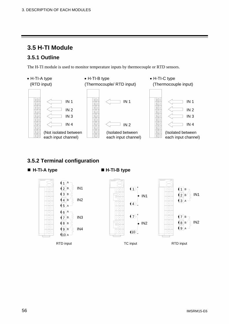
3. DESCRIPTION OF EACH MODULES
IMSRM15-E6 56
3.5 H-TI Module 3.5.1 Outline The H-TI module is used to monitor temperature inputs by thermocouple or RTD sensors. • H-TI-A type • H-TI-B type • H-TI-C type
(RTD input) (Thermocouple/ RTD input) (Thermocouple input)
IN 1
IN 2IN 3
IN 4
(Not isolated betweeneach input channel)
IN 1
IN 2
(Isolated betweeneach input channel)
IN 1
IN 2IN 3
IN 4
(Isolated betweeneach input channel)
3.5.2 Terminal configuration
H-TI-A type H-TI-B type
3
4 5
B
B
A
2 1
B
A
8
9 10
B
B
A
7 6
B
A
IN1
IN2
IN3
IN4
7
8 9
B
B
A
1
2 3
B
B
A
IN1
IN2
RTD input RTD input TC input
1
4
+
−
7
10
+
−
IN1
IN2
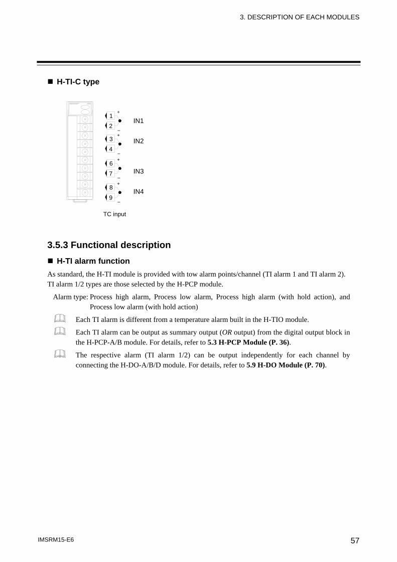
3. DESCRIPTION OF EACH MODULES
IMSRM15-E6 57
H-TI-C type 3.5.3 Functional description
H-TI alarm function As standard, the H-TI module is provided with tow alarm points/channel (TI alarm 1 and TI alarm 2). TI alarm 1/2 types are those selected by the H-PCP module.
Alarm type: Process high alarm, Process low alarm, Process high alarm (with hold action), and Process low alarm (with hold action)
Each TI alarm is different from a temperature alarm built in the H-TIO module.
Each TI alarm can be output as summary output (OR output) from the digital output block in the H-PCP-A/B module. For details, refer to 5.3 H-PCP Module (P. 36).
The respective alarm (TI alarm 1/2) can be output independently for each channel by connecting the H-DO-A/B/D module. For details, refer to 5.9 H-DO Module (P. 70).
8
9
+
−
6
7
+
−
3
4
+
−
1
2
+
−
IN1
IN2
IN3
IN4
TC input
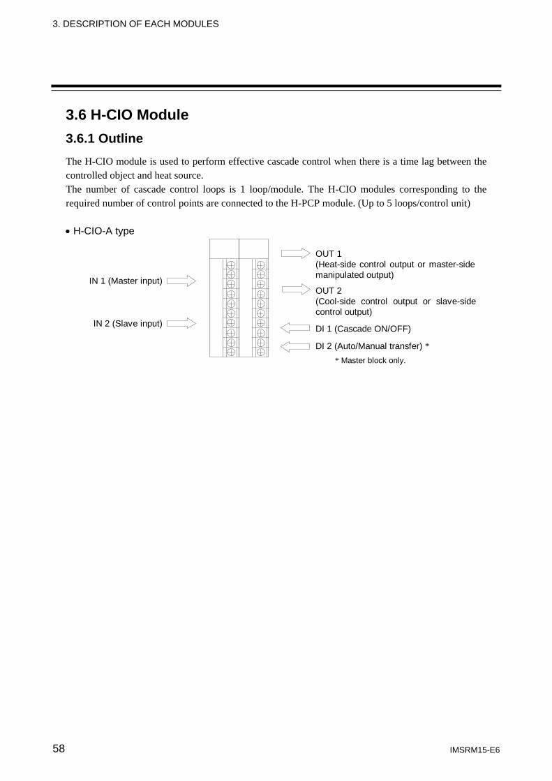
3. DESCRIPTION OF EACH MODULES
IMSRM15-E6 58
3.6 H-CIO Module 3.6.1 Outline The H-CIO module is used to perform effective cascade control when there is a time lag between the controlled object and heat source. The number of cascade control loops is 1 loop/module. The H-CIO modules corresponding to the required number of control points are connected to the H-PCP module. (Up to 5 loops/control unit) • H-CIO-A type
IN 1 (Master input)
IN 2 (Slave input)
OUT 1(Heat-side control output or master-sidemanipulated output)
OUT 2(Cool-side control output or slave-sidecontrol output)
DI 1 (Cascade ON/OFF)
DI 2 (Auto/Manual transfer) ** Master block only.
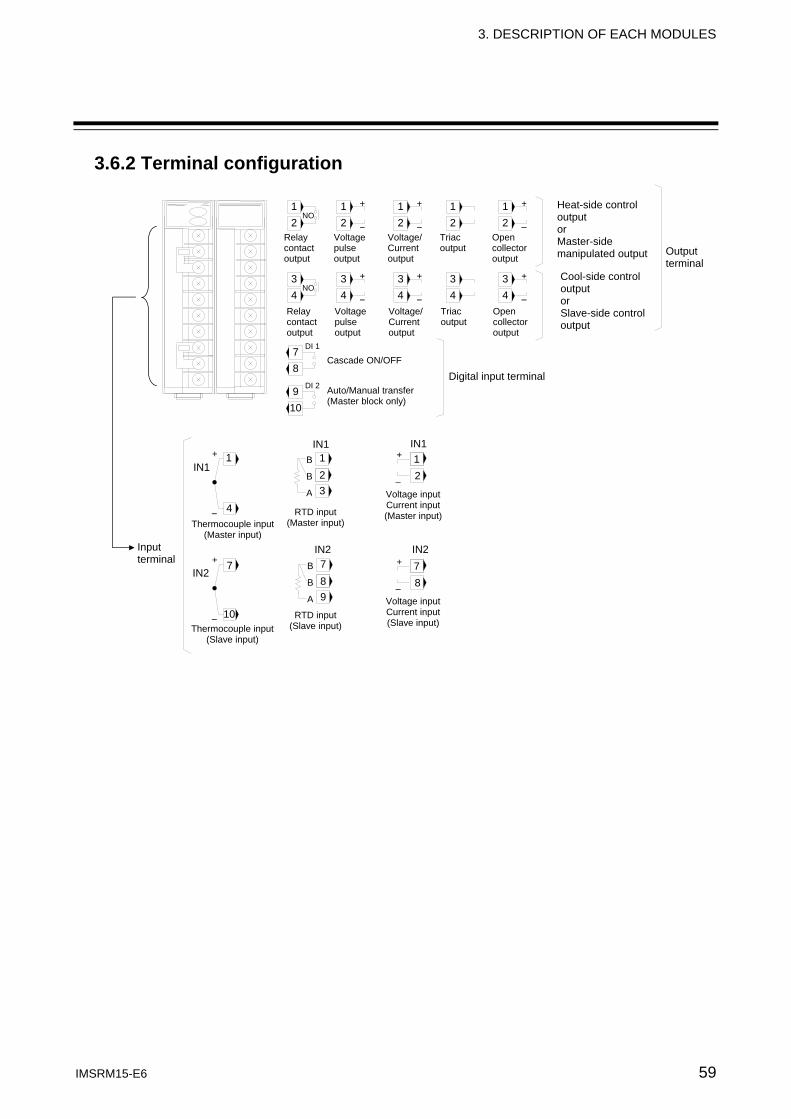
3. DESCRIPTION OF EACH MODULES
IMSRM15-E6 59
3.6.2 Terminal configuration
Open collector output
Relay contact output
Voltage pulse output
Voltage/ Current output
Triac output
Heat-side control output or Master-side manipulated output
Cool-side control output or Slave-side control output
Digital input terminal Cascade ON/OFF
1
4
+
−
7
10
+
−
Thermocouple input (Master input)
Thermocouple input (Slave input)
Input terminal
IN1
IN2 7 8 9
B
B
A
1 2 3
B
B
A
RTD input (Master input)
RTD input (Slave input)
IN1
IN2
12
+
−
IN1
IN2
Voltage inputCurrent input(Master input)
Voltage inputCurrent input(Slave input)
78
+
−
Auto/Manual transfer (Master block only)
Relay contact output
Open collector output
Voltage pulse output
Voltage/ Current output
Triac output
Output terminal
DI 2
DI 1
NO 1 2
12
+
−
12
+
−
12
12
+
−
NO 3 4
34
+
−
34
+
−
34
34
+
−
7 8
9 10
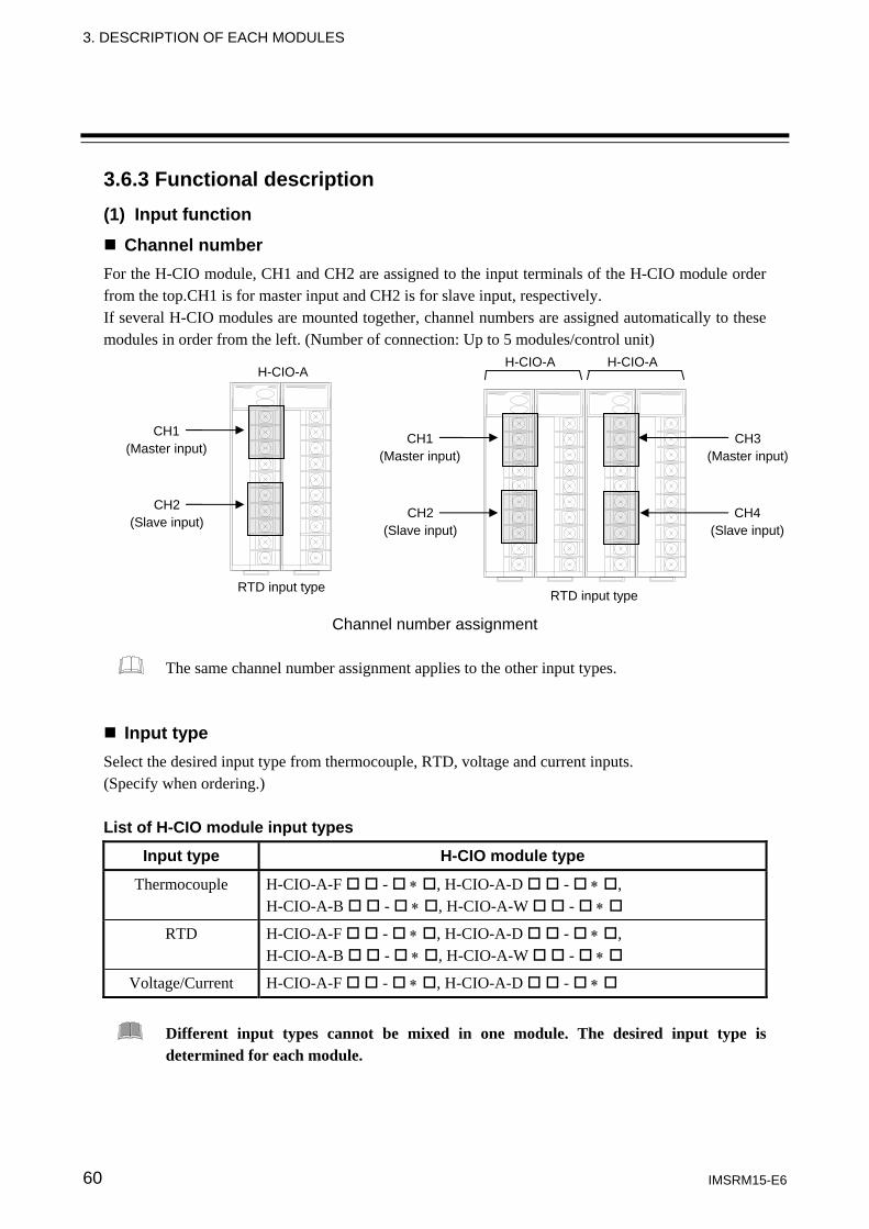
3. DESCRIPTION OF EACH MODULES
IMSRM15-E6 60
3.6.3 Functional description (1) Input function
Channel number For the H-CIO module, CH1 and CH2 are assigned to the input terminals of the H-CIO module order from the top.CH1 is for master input and CH2 is for slave input, respectively. If several H-CIO modules are mounted together, channel numbers are assigned automatically to these modules in order from the left. (Number of connection: Up to 5 modules/control unit)
Channel number assignment
The same channel number assignment applies to the other input types.
Input type Select the desired input type from thermocouple, RTD, voltage and current inputs. (Specify when ordering.) List of H-CIO module input types
Input type H-CIO module type
Thermocouple H-CIO-A-F - ∗ , H-CIO-A-D - ∗ , H-CIO-A-B - ∗ , H-CIO-A-W - ∗
RTD H-CIO-A-F - ∗ , H-CIO-A-D - ∗ , H-CIO-A-B - ∗ , H-CIO-A-W - ∗
Voltage/Current H-CIO-A-F - ∗ , H-CIO-A-D - ∗
Different input types cannot be mixed in one module. The desired input type is determined for each module.
RTD input type
CH1 (Master input)
CH2 (Slave input)
RTD input type
CH1 (Master input)
CH2 (Slave input)
CH3 (Master input)
CH4 (Slave input)
H-CIO-A H-CIO-A H-CIO-A
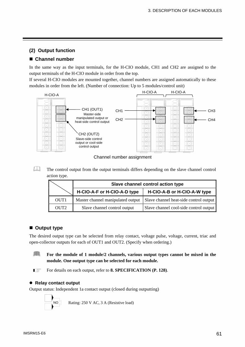
3. DESCRIPTION OF EACH MODULES
IMSRM15-E6 61
(2) Output function
Channel number In the same way as the input terminals, for the H-CIO module, CH1 and CH2 are assigned to the output terminals of the H-CIO module in order from the top. If several H-CIO modules are mounted together, channel numbers are assigned automatically to these modules in order from the left. (Number of connection: Up to 5 modules/control unit)
Channel number assignment
The control output from the output terminals differs depending on the slave channel control action type.
Slave channel control action type H-CIO-A-F or H-CIO-A-D type H-CIO-A-B or H-CIO-A-W type
OUT1 Master channel manipulated output Slave channel heat-side control output
OUT2 Slave channel control output Slave channel cool-side control output
Output type The desired output type can be selected from relay contact, voltage pulse, voltage, current, triac and open-collector outputs for each of OUT1 and OUT2. (Specify when ordering.)
For the module of 1 module/2 channels, various output types cannot be mixed in the module. One output type can be selected for each module.
For details on each output, refer to 8. SPECIFICATION (P. 128).
Relay contact output Output status: Independent 1a contact output (closed during outputting)
NO Rating: 250 V AC, 3 A (Resistive load)
H-CIO-A H-CIO-A
CH2 (OUT2) Slave-side control output or cool-side
control output
CH1 (OUT1) Master-side
manipulated output or heat-side control output
CH1
H-CIO-A
CH2
CH3
CH4
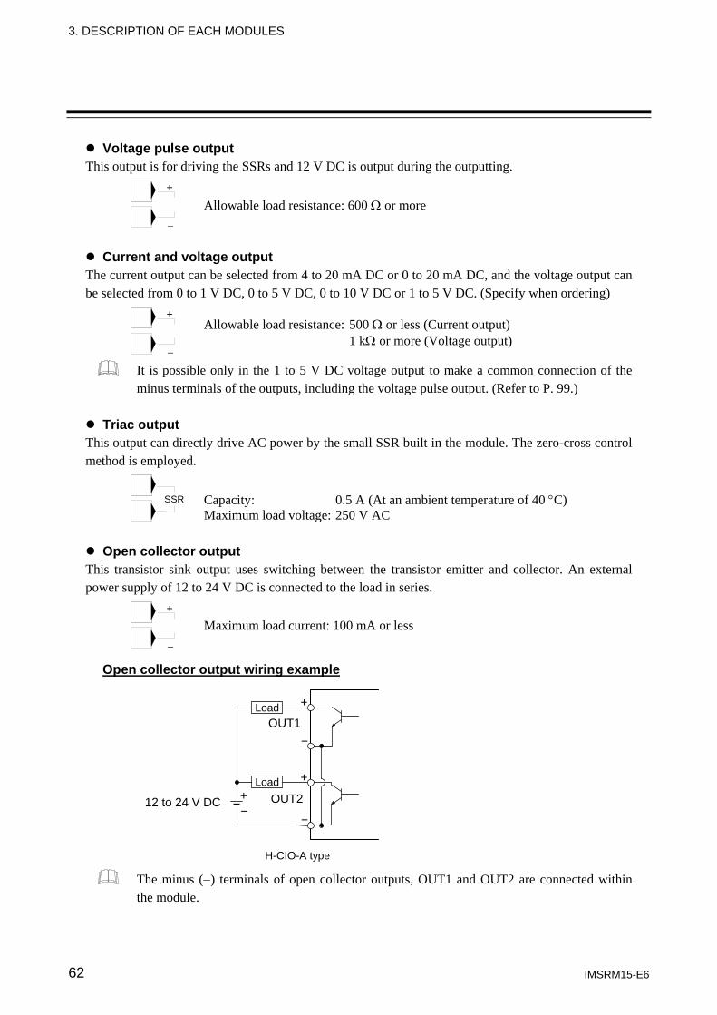
3. DESCRIPTION OF EACH MODULES
IMSRM15-E6 62
Voltage pulse output This output is for driving the SSRs and 12 V DC is output during the outputting.
Current and voltage output The current output can be selected from 4 to 20 mA DC or 0 to 20 mA DC, and the voltage output can be selected from 0 to 1 V DC, 0 to 5 V DC, 0 to 10 V DC or 1 to 5 V DC. (Specify when ordering)
It is possible only in the 1 to 5 V DC voltage output to make a common connection of the minus terminals of the outputs, including the voltage pulse output. (Refer to P. 99.)
Triac output
This output can directly drive AC power by the small SSR built in the module. The zero-cross control method is employed.
Open collector output This transistor sink output uses switching between the transistor emitter and collector. An external power supply of 12 to 24 V DC is connected to the load in series.
Open collector output wiring example
The minus (−) terminals of open collector outputs, OUT1 and OUT2 are connected within the module.
+
−
Allowable load resistance: 600 Ω or more
+
−
Allowable load resistance: 500 Ω or less (Current output) 1 kΩ or more (Voltage output)
12 to 24 V DC OUT2
OUT1
+ +
+
- -
-
H-CIO-A type
Load
Load
Maximum load current: 100 mA or less
+
−
Capacity: 0.5 A (At an ambient temperature of 40 °C) Maximum load voltage: 250 V AC
SSR
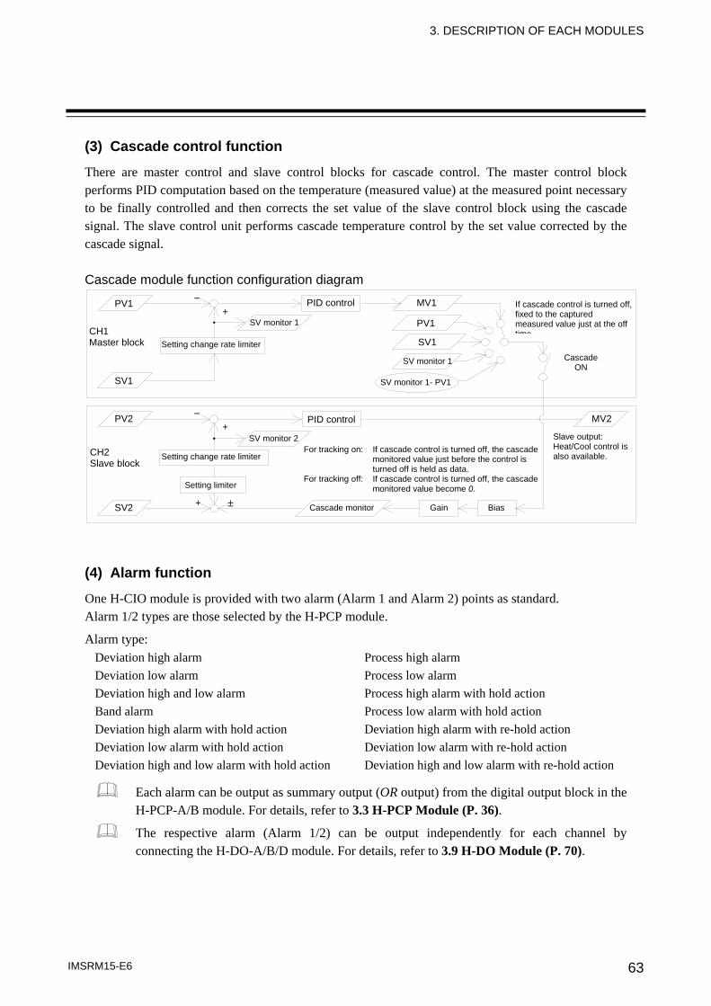
3. DESCRIPTION OF EACH MODULES
IMSRM15-E6 63
(3) Cascade control function
There are master control and slave control blocks for cascade control. The master control block performs PID computation based on the temperature (measured value) at the measured point necessary to be finally controlled and then corrects the set value of the slave control block using the cascade signal. The slave control unit performs cascade temperature control by the set value corrected by the cascade signal. Cascade module function configuration diagram
PV1
SV1
PV2
SV2
PID control
SV monitor 1
Setting change rate limiter
Setting limiter
SV monitor 2
Cascade monitor Gain Bias
PV1
MV1
SV1
SV monitor 1
SV monitor 1- PV1
MV2
CH1 Master block
CH2 Slave block
For tracking on: If cascade control is turned off, the cascade monitored value just before the control is turned off is held as data.
For tracking off: If cascade control is turned off, the cascade monitored value become 0.
If cascade control is turned off, fixed to the captured measured value just at the off time
CascadeON
Slave output: Heat/Cool control is also available.
− +
− +
+ ±
PID control
Setting change rate limiter
(4) Alarm function
One H-CIO module is provided with two alarm (Alarm 1 and Alarm 2) points as standard. Alarm 1/2 types are those selected by the H-PCP module.
Alarm type: Deviation high alarm Process high alarm Deviation low alarm Process low alarm Deviation high and low alarm Process high alarm with hold action Band alarm Process low alarm with hold action Deviation high alarm with hold action Deviation high alarm with re-hold action Deviation low alarm with hold action Deviation low alarm with re-hold action Deviation high and low alarm with hold action Deviation high and low alarm with re-hold action
Each alarm can be output as summary output (OR output) from the digital output block in the H-PCP-A/B module. For details, refer to 3.3 H-PCP Module (P. 36).
The respective alarm (Alarm 1/2) can be output independently for each channel by connecting the H-DO-A/B/D module. For details, refer to 3.9 H-DO Module (P. 70).
3. DESCRIPTION OF EACH MODULES
IMSRM15-E6 64
(5) Loop break alarm function
The loop break alarm function is used to detect a load (heater) break, a failure occurring in any external operating device (magnet relay, etc.) or a failure occurring in the control system (control loop) caused by an input (sensor) break. (Refer to P. 124.)
The loop break alarm can be output as summary output (OR output) from the digital output block in the H-PCP-A/B module. For details, refer to 3.3 H-PCP Module (P. 36).
The loop break alarm can be output independently for each channel by connecting the H-DO-A/B/D module. For details, refer to 3.9 H-DO Module (P. 70).
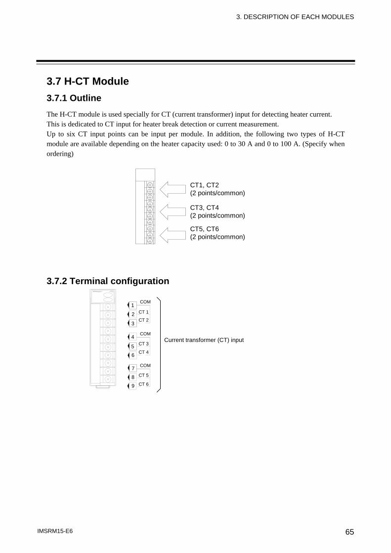
3. DESCRIPTION OF EACH MODULES
IMSRM15-E6 65
3.7 H-CT Module 3.7.1 Outline The H-CT module is used specially for CT (current transformer) input for detecting heater current. This is dedicated to CT input for heater break detection or current measurement. Up to six CT input points can be input per module. In addition, the following two types of H-CT module are available depending on the heater capacity used: 0 to 30 A and 0 to 100 A. (Specify when ordering)
CT1, CT2(2 points/common)
CT3, CT4(2 points/common)
CT5, CT6(2 points/common)
3.7.2 Terminal configuration
5 6
7
8
3
1
2
4
9
COM
COM
COM
CT 1
CT 2
CT 3
CT 4
CT 5
CT 6
Current transformer (CT) input
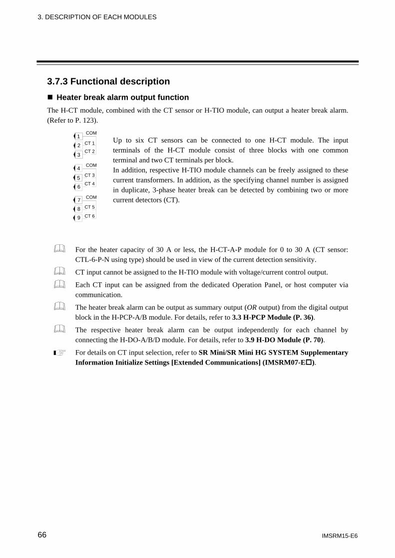
3. DESCRIPTION OF EACH MODULES
IMSRM15-E6 66
3.7.3 Functional description Heater break alarm output function
The H-CT module, combined with the CT sensor or H-TIO module, can output a heater break alarm. (Refer to P. 123).
Up to six CT sensors can be connected to one H-CT module. The input terminals of the H-CT module consist of three blocks with one common terminal and two CT terminals per block. In addition, respective H-TIO module channels can be freely assigned to these current transformers. In addition, as the specifying channel number is assigned in duplicate, 3-phase heater break can be detected by combining two or more current detectors (CT).
For the heater capacity of 30 A or less, the H-CT-A-P module for 0 to 30 A (CT sensor: CTL-6-P-N using type) should be used in view of the current detection sensitivity.
CT input cannot be assigned to the H-TIO module with voltage/current control output.
Each CT input can be assigned from the dedicated Operation Panel, or host computer via communication.
The heater break alarm can be output as summary output (OR output) from the digital output block in the H-PCP-A/B module. For details, refer to 3.3 H-PCP Module (P. 36).
The respective heater break alarm can be output independently for each channel by connecting the H-DO-A/B/D module. For details, refer to 3.9 H-DO Module (P. 70).
For details on CT input selection, refer to SR Mini/SR Mini HG SYSTEM Supplementary Information Initialize Settings [Extended Communications] (IMSRM07-E ).
5 6
7
8
3
1
2
4
9
COM
COM
COM
CT 1
CT 2
CT 3
CT 4
CT 5
CT 6
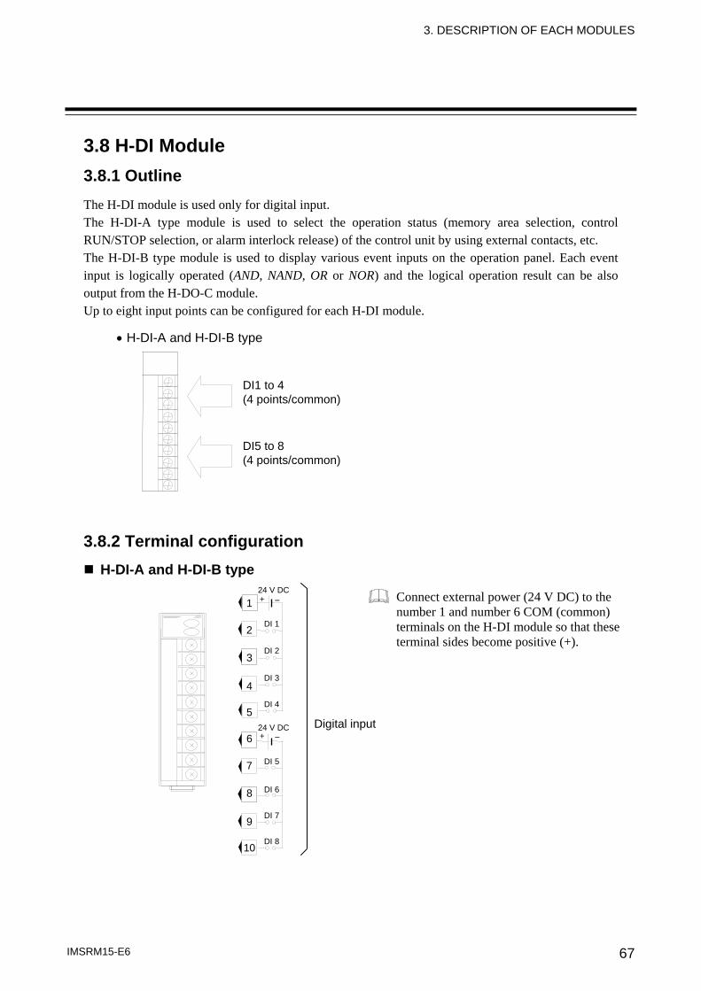
3. DESCRIPTION OF EACH MODULES
IMSRM15-E6 67
3.8 H-DI Module 3.8.1 Outline The H-DI module is used only for digital input. The H-DI-A type module is used to select the operation status (memory area selection, control RUN/STOP selection, or alarm interlock release) of the control unit by using external contacts, etc. The H-DI-B type module is used to display various event inputs on the operation panel. Each event input is logically operated (AND, NAND, OR or NOR) and the logical operation result can be also output from the H-DO-C module. Up to eight input points can be configured for each H-DI module.
• H-DI-A and H-DI-B type 3.8.2 Terminal configuration
H-DI-A and H-DI-B type
DI1 to 4 (4 points/common)
DI5 to 8 (4 points/common)
Digital input
1
2
3
4
5
6
7
8
9
10
24 V DC
24 V DC
+ −
+ −
DI 1
DI 2
DI 3
DI 4
DI 5
DI 6
DI 7
DI 8
Connect external power (24 V DC) to the number 1 and number 6 COM (common) terminals on the H-DI module so that these terminal sides become positive (+).

3. DESCRIPTION OF EACH MODULES
IMSRM15-E6 68
3.8.3 Functional description (1) Digital input function (H-DI-A) This is a function to switch the operation status of the control unit (refer to below) using the external signal fed into the H-DI-A module which is connected to the control unit. The operation status can be switched over by the open/close state of the digital input terminals 1 to 8 of the H-DI-A module.
Operation state types: Memory area selection, Control RUN/STOP selection and Alarm interlock release
For memory area selection, configure an external contact circuit or use a contact output signal from the PLC, if necessary.
After the contact is closed, it takes a short time until the action of this device is actually selected. Therefore, pay attention to this delay time if the device is used together with a PLC, etc.
Connect external power (24 V DC) to the number 1 and number 6 COM (common) terminals on the H-DI module so that these terminal sides become positive (+).
Control area
Terminal No. 1 2 3 4 5 6 7 8
1 - 2 − × − × − × − ×1 - 3 − − × × − − × ×1 - 4 − − − − × × × ×
−: Open ×: Closed
The memory area (control area) is established by closing terminal number 5 (ENABLE terminal). [Function mode 1*]
* The function mode types below can be selected for the digital input function of the H-DI-A module. The digital inputs (DI) function can be set following function mode 1 to 2 in operation panel or host communication (initialize settings [extended communications]).
Function mode 1 (factory set value) − Memory area selection (ENABLE terminal is used)
After area selection setting, the actual area is changed by detecting the ENABLE edge. − Control RUN/STOP selection − Alarm interlock release
Function mode 2 − Memory area selection
The actual area is changed approximately 2 seconds after area selection setting. − Control RUN/STOP selection − Alarm interlock release
Alarm interlock release (contact closed: alarm interlock release) (No alarm interlock function is activated if the contact is in the normally closed state.)
Control RUN/STOP selection (contact closed: RUN, contact open: STOP)
Unused
(COM)
(COM)
(1)
(2)
(4)
SET
2
3
4
5
− + 1
− + 6
7
8
9
10
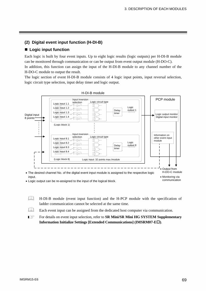
3. DESCRIPTION OF EACH MODULES
IMSRM15-E6 69
(2) Digital event input function (H-DI-B)
Logic input function Each logic is built by four event inputs. Up to eight logic results (logic outputs) per H-DI-B module can be monitored through communication or can be output from event output module (H-DO-C). In addition, this function can assign the input of the H-DI-B module to any channel number of the H-DO-C module to output the result. The logic section of event H-DI-B module consists of 4 logic input points, input reversal selection, logic circuit type selection, input delay timer and logic output.
H-DI-B module (event input function) and the H-PCP module with the specification of ladder communication cannot be selected at the same time.
Each event input can be assigned from the dedicated host computer via communication.
For details on event input selection, refer to SR Mini/SR Mini HG SYSTEM Supplementary Information Initialize Settings [Extended Communications] (IMSRM07-E ).
Digital input 8 points
Logic input 1.1
Logic input 1.2
Logic input 1.3
Logic input 1.4
Logic input 8.1
Logic input 8.2
Logic input 8.3
Logic input 8.4
Input inversion selection Logic circuit type
Delay timer
Logic output 1
(Logic block 1)
(Logic block 8) Logic input: 32 points max./module
H-DI-B module
PCP module
Logic output monitorDigital input monitor
Information on other event input module
• Output from H-DO-C module
• Monitoring via communication
• The desired channel No. of the digital event input module is assigned to the respective logic input.
• Logic output can be re-assigned to the input of the logical block.
Logic circuit typeInput inversion selection
Delay timer
Logic output 8
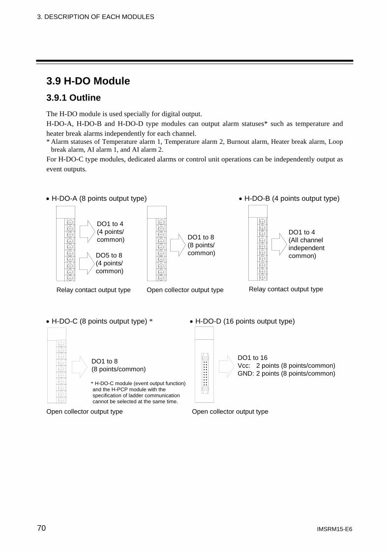
3. DESCRIPTION OF EACH MODULES
IMSRM15-E6 70
3.9 H-DO Module 3.9.1 Outline The H-DO module is used specially for digital output. H-DO-A, H-DO-B and H-DO-D type modules can output alarm statuses* such as temperature and heater break alarms independently for each channel. * Alarm statuses of Temperature alarm 1, Temperature alarm 2, Burnout alarm, Heater break alarm, Loop
break alarm, AI alarm 1, and AI alarm 2. For H-DO-C type modules, dedicated alarms or control unit operations can be independently output as event outputs. • H-DO-A (8 points output type) • H-DO-B (4 points output type)
DO1 to 4(4 points/common)
DO5 to 8(4 points/common)
DO1 to 8(8 points/common)
DO1 to 4(All channelindependentcommon)
Relay contact output type Open collector output type Relay contact output type
• H-DO-C (8 points output type) * • H-DO-D (16 points output type)
Open collector output type Open collector output type
DO1 to 8 (8 points/common)
* H-DO-C module (event output function) and the H-PCP module with the specification of ladder communication cannot be selected at the same time.
DO1 to 16 Vcc: 2 points (8 points/common) GND: 2 points (8 points/common)
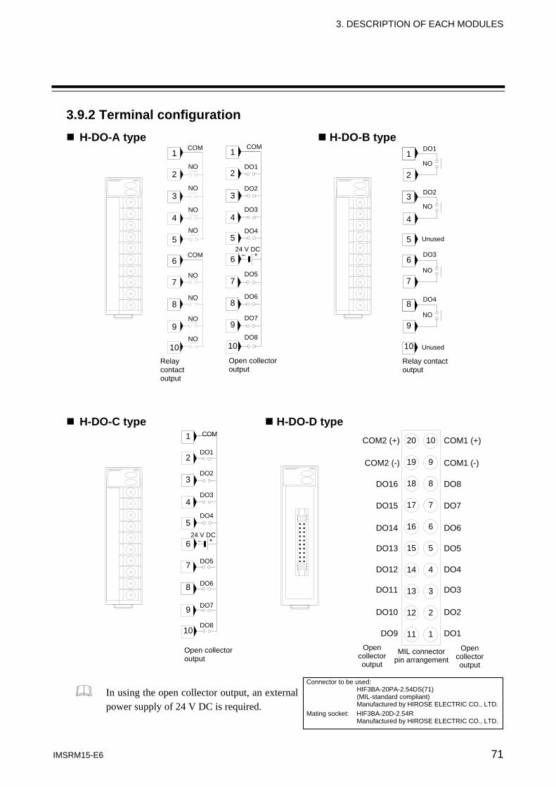
3. DESCRIPTION OF EACH MODULES
IMSRM15-E6 71
3.9.2 Terminal configuration H-DO-A type H-DO-B type
H-DO-C type H-DO-D type
In using the open collector output, an external power supply of 24 V DC is required.
1
2 NO
3
4
5
NO
NO
NO
6
7 NO
8
9
10
NO
NO
NO
Relay contact output
1
2
3
4
5
6
7
8
9
10
Open collector output
COM
COM
COM
DO1
DO2
DO3
DO4
24 V DC
DO5
DO6
DO7
DO8
1
2
3
4
5
6
7
8
9
10
NO
NO
NO
NO
DO1
DO2
DO3
DO4
Relay contact output
1
2
3
4
5
6
7
8
9
10
Open collector output
COM
DO1
DO2
DO3
DO4
24 V DC
DO5
DO6
DO7
DO8
+−
+ −
Unused
Unused
Connector to be used: HIF3BA-20PA-2.54DS(71) (MIL-standard compliant) Manufactured by HIROSE ELECTRIC CO., LTD.Mating socket: HIF3BA-20D-2.54R Manufactured by HIROSE ELECTRIC CO., LTD.
DO1
DO2
DO3
DO4
DO5
DO6
DO7
DO8
COM1 (-)
COM1 (+)
DO9
DO10
DO11
DO12
DO13
DO14
DO15
DO16
COM2 (-)
COM2 (+)
Open collector output
Open collector output
MIL connector pin arrangement
20
11
19
18
17
16
15
14
13
12
10
1
9
8
7
6
5
4
3
2
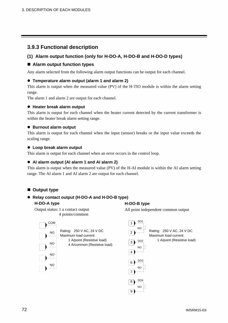
3. DESCRIPTION OF EACH MODULES
IMSRM15-E6 72
3.9.3 Functional description (1) Alarm output function (only for H-DO-A, H-DO-B and H-DO-D types)
Alarm output function types Any alarm selected from the following alarm output functions can be output for each channel.
Temperature alarm output (alarm 1 and alarm 2) This alarm is output when the measured value (PV) of the H-TIO module is within the alarm setting range. The alarm 1 and alarm 2 are output for each channel.
Heater break alarm output This alarm is output for each channel when the heater current detected by the current transformer is within the heater break alarm setting range.
Burnout alarm output This alarm is output for each channel when the input (sensor) breaks or the input value exceeds the scaling range.
Loop break alarm output This alarm is output for each channel when an error occurs in the control loop.
AI alarm output (AI alarm 1 and AI alarm 2) This alarm is output when the measured value (PV) of the H-AI module is within the AI alarm setting range. The AI alarm 1 and AI alarm 2 are output for each channel.
Output type Relay contact output (H-DO-A and H-DO-B type)
H-DO-A type Output status: 1 a contact output
4 points/common
NO
COM
NO
NO
NO Rating: 250 V AC, 24 V DC Maximum load current: 1 A/point (Resistive load) 4 A/common (Resistive load)
H-DO-B type All point independent common output
1
2
3
4
6
7
8
9
NO
NO
NO
NO
DO1
DO2
DO3
DO4
Rating: 250 V AC, 24 V DC Maximum load current: 1 A/point (Resistive load)
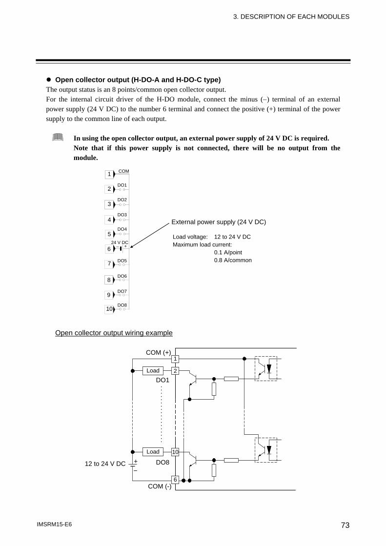
3. DESCRIPTION OF EACH MODULES
IMSRM15-E6 73
Open collector output (H-DO-A and H-DO-C type) The output status is an 8 points/common open collector output. For the internal circuit driver of the H-DO module, connect the minus (−) terminal of an external power supply (24 V DC) to the number 6 terminal and connect the positive (+) terminal of the power supply to the common line of each output.
In using the open collector output, an external power supply of 24 V DC is required. Note that if this power supply is not connected, there will be no output from the module.
Open collector output wiring example
External power supply (24 V DC)
Load voltage: 12 to 24 V DC Maximum load current: 0.1 A/point 0.8 A/common
1
2
3
4
5
6
7
8
9
10
COM
DO1
DO2
DO3
DO4
24 V DC
DO5
DO6
DO7
DO8
+ −
12 to 24 V DC- +
10
COM (+)
COM (-)
DO1
DO8
⋅⋅⋅⋅⋅⋅⋅⋅⋅⋅⋅⋅⋅⋅⋅⋅⋅⋅Load
6
2
1
Load
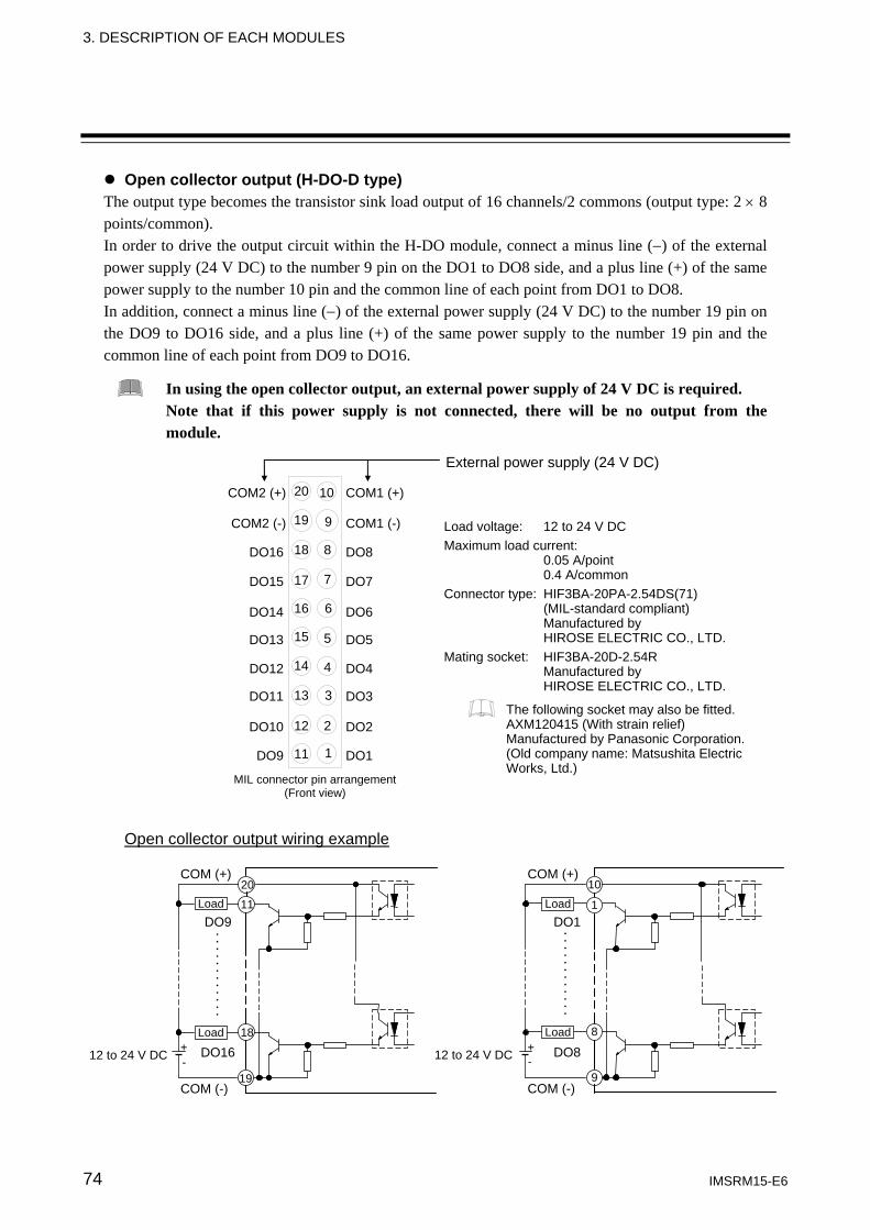
3. DESCRIPTION OF EACH MODULES
IMSRM15-E6 74
Open collector output (H-DO-D type) The output type becomes the transistor sink load output of 16 channels/2 commons (output type: 2 × 8 points/common). In order to drive the output circuit within the H-DO module, connect a minus line (−) of the external power supply (24 V DC) to the number 9 pin on the DO1 to DO8 side, and a plus line (+) of the same power supply to the number 10 pin and the common line of each point from DO1 to DO8. In addition, connect a minus line (−) of the external power supply (24 V DC) to the number 19 pin on the DO9 to DO16 side, and a plus line (+) of the same power supply to the number 19 pin and the common line of each point from DO9 to DO16.
In using the open collector output, an external power supply of 24 V DC is required. Note that if this power supply is not connected, there will be no output from the module.
Open collector output wiring example
12 to 24 V DC
Load
- +
20
11
19
18
COM (+)
COM (-)
DO9
DO16
⋅ ⋅ ⋅ ⋅ ⋅ ⋅ ⋅ ⋅ ⋅ ⋅ ⋅ ⋅ Load
12 to 24 V DC -+
COM (+)
COM (-)
DO1
DO8
9
10
⋅⋅⋅⋅⋅⋅⋅⋅⋅⋅⋅⋅Load 8
Load 1
20
19
18
17
16
15
14
13
12
11
10
9
8
7
6
5
4
3
2
1 DO1
DO2
DO3
DO4
DO5
DO6
DO7
DO8
COM1 (-)
COM1 (+)
DO9
DO10
DO11
DO12
DO13
DO14
DO15
DO16
COM2 (-)
COM2 (+)
MIL connector pin arrangement(Front view)
External power supply (24 V DC)
Load voltage: 12 to 24 V DC Maximum load current: 0.05 A/point 0.4 A/common Connector type: HIF3BA-20PA-2.54DS(71) (MIL-standard compliant) Manufactured by HIROSE ELECTRIC CO., LTD. Mating socket: HIF3BA-20D-2.54R Manufactured by HIROSE ELECTRIC CO., LTD.
The following socket may also be fitted. AXM120415 (With strain relief) Manufactured by Panasonic Corporation. (Old company name: Matsushita Electric Works, Ltd.)
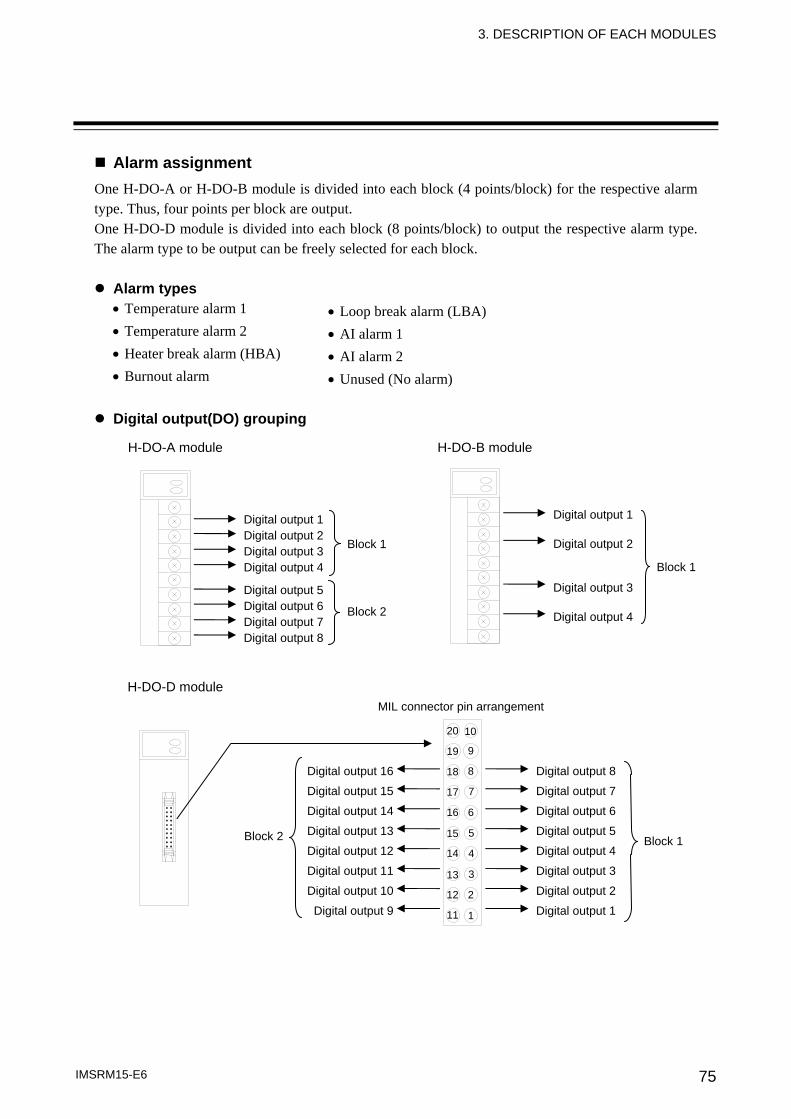
3. DESCRIPTION OF EACH MODULES
IMSRM15-E6 75
Alarm assignment One H-DO-A or H-DO-B module is divided into each block (4 points/block) for the respective alarm type. Thus, four points per block are output. One H-DO-D module is divided into each block (8 points/block) to output the respective alarm type. The alarm type to be output can be freely selected for each block.
Alarm types • Temperature alarm 1 • Temperature alarm 2 • Heater break alarm (HBA) • Burnout alarm
Digital output(DO) grouping
• Loop break alarm (LBA) • AI alarm 1 • AI alarm 2 • Unused (No alarm)
H-DO-A module
Digital output 1 Digital output 2 Digital output 3 Digital output 4
Digital output 5 Digital output 6 Digital output 7 Digital output 8
Block 1
Block 2
H-DO-B module
Digital output 1 Digital output 2 Digital output 3 Digital output 4
Block 1
H-DO-D module
20
19
18
17
16
15
14
13
12
11
10
9
8
7
6
5
4
3
2
1
MIL connector pin arrangement
Digital output 8
Digital output 7
Digital output 6
Digital output 5
Digital output 4
Digital output 3
Digital output 2
Digital output 1
Digital output 16
Digital output 15
Digital output 14
Digital output 13
Digital output 12
Digital output 11
Digital output 10
Digital output 9
Block 1 Block 2
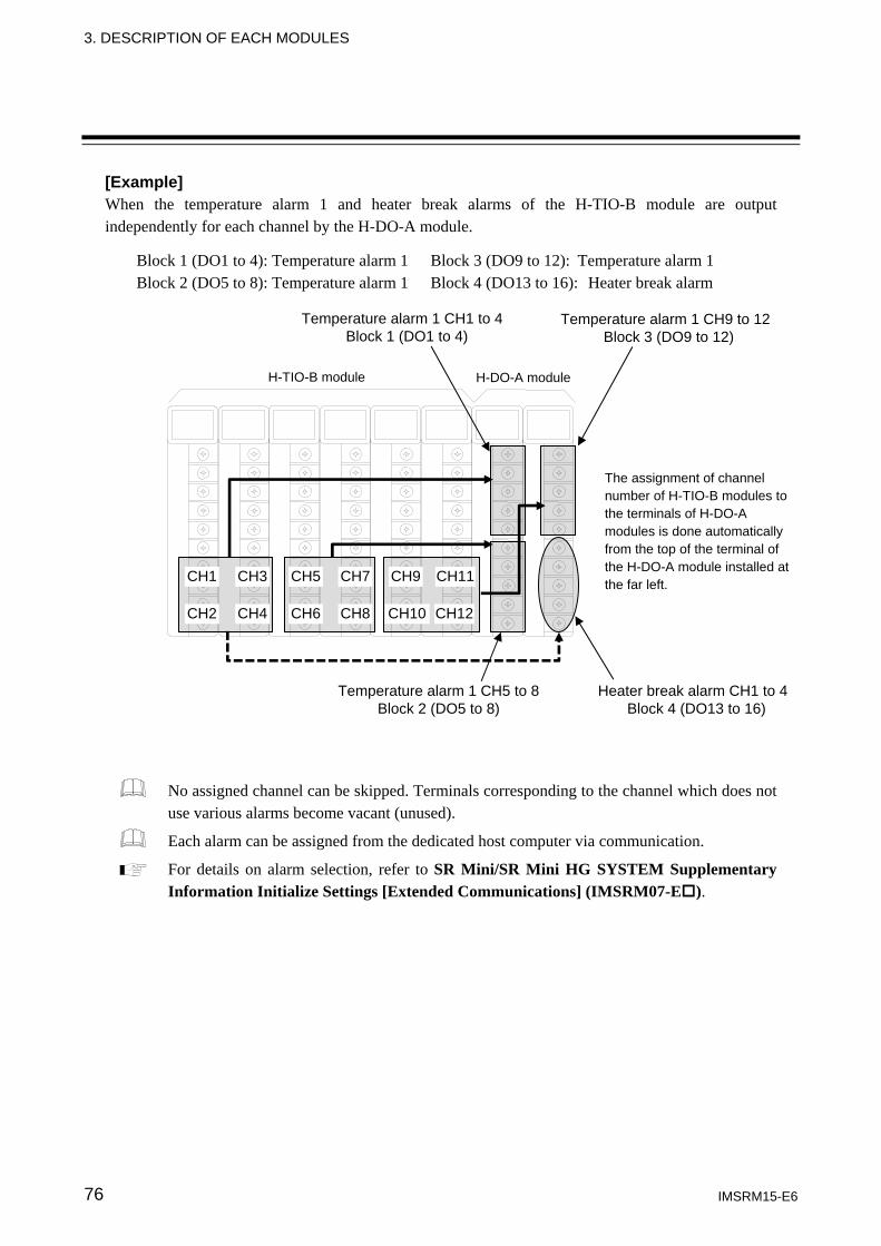
3. DESCRIPTION OF EACH MODULES
IMSRM15-E6 76
[Example] When the temperature alarm 1 and heater break alarms of the H-TIO-B module are output independently for each channel by the H-DO-A module.
Block 1 (DO1 to 4): Temperature alarm 1 Block 3 (DO9 to 12): Temperature alarm 1 Block 2 (DO5 to 8): Temperature alarm 1 Block 4 (DO13 to 16): Heater break alarm
No assigned channel can be skipped. Terminals corresponding to the channel which does not use various alarms become vacant (unused).
Each alarm can be assigned from the dedicated host computer via communication.
For details on alarm selection, refer to SR Mini/SR Mini HG SYSTEM Supplementary Information Initialize Settings [Extended Communications] (IMSRM07-E ).
H-TIO-B module H-DO-A module
CH1
CH2
CH3
CH4
CH5
CH6
CH7
CH8
CH9
CH10
CH11
CH12
Temperature alarm 1 CH1 to 4Block 1 (DO1 to 4)
Temperature alarm 1 CH9 to 12Block 3 (DO9 to 12)
Temperature alarm 1 CH5 to 8Block 2 (DO5 to 8)
Heater break alarm CH1 to 4Block 4 (DO13 to 16)
The assignment of channel number of H-TIO-B modules to the terminals of H-DO-A modules is done automatically from the top of the terminal of the H-DO-A module installed at the far left.
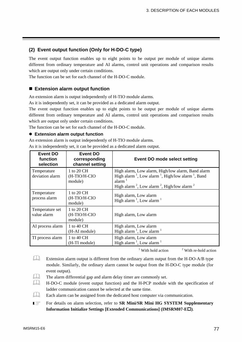
3. DESCRIPTION OF EACH MODULES
IMSRM15-E6 77
(2) Event output function (Only for H-DO-C type)
The event output function enables up to eight points to be output per module of unique alarms different from ordinary temperature and AI alarms, control unit operations and comparison results which are output only under certain conditions. The function can be set for each channel of the H-DO-C module.
Extension alarm output function An extension alarm is output independently of H-TIO module alarms. As it is independently set, it can be provided as a dedicated alarm output. The event output function enables up to eight points to be output per module of unique alarms different from ordinary temperature and AI alarms, control unit operations and comparison results which are output only under certain conditions. The function can be set for each channel of the H-DO-C module.
Extension alarm output function An extension alarm is output independently of H-TIO module alarms. As it is independently set, it can be provided as a dedicated alarm output.
Event DO function selection
Event DO corresponding channel setting
Event DO mode select setting
Temperature deviation alarm
1 to 20 CH (H-TIO/H-CIO module)
High alarm, Low alarm, High/low alarm, Band alarm High alarm 1, Low alarm 1, High/low alarm 1, Band alarm 1 High alarm 2, Low alarm 2, High/low alarm 2
Temperature process alarm
1 to 20 CH (H-TIO/H-CIO module)
High alarm, Low alarm High alarm 1, Low alarm 1
Temperature set value alarm
1 to 20 CH (H-TIO/H-CIO module)
High alarm, Low alarm
AI process alarm 1 to 40 CH (H-AI module)
High alarm, Low alarm High alarm 1, Low alarm 1
TI process alarm 1 to 40 CH (H-TI module)
High alarm, Low alarm High alarm 1, Low alarm 1
1 With hold action 2 With re-hold action
Extension alarm output is different from the ordinary alarm output from the H-DO-A/B type module. Similarly, the ordinary alarm cannot be output from the H-DO-C type module (for event output). The alarm differential gap and alarm delay timer are commonly set. H-DO-C module (event output function) and the H-PCP module with the specification of ladder communication cannot be selected at the same time. Each alarm can be assigned from the dedicated host computer via communication.
For details on alarm selection, refer to SR Mini/SR Mini HG SYSTEM Supplementary Information Initialize Settings [Extended Communications] (IMSRM07-E ).
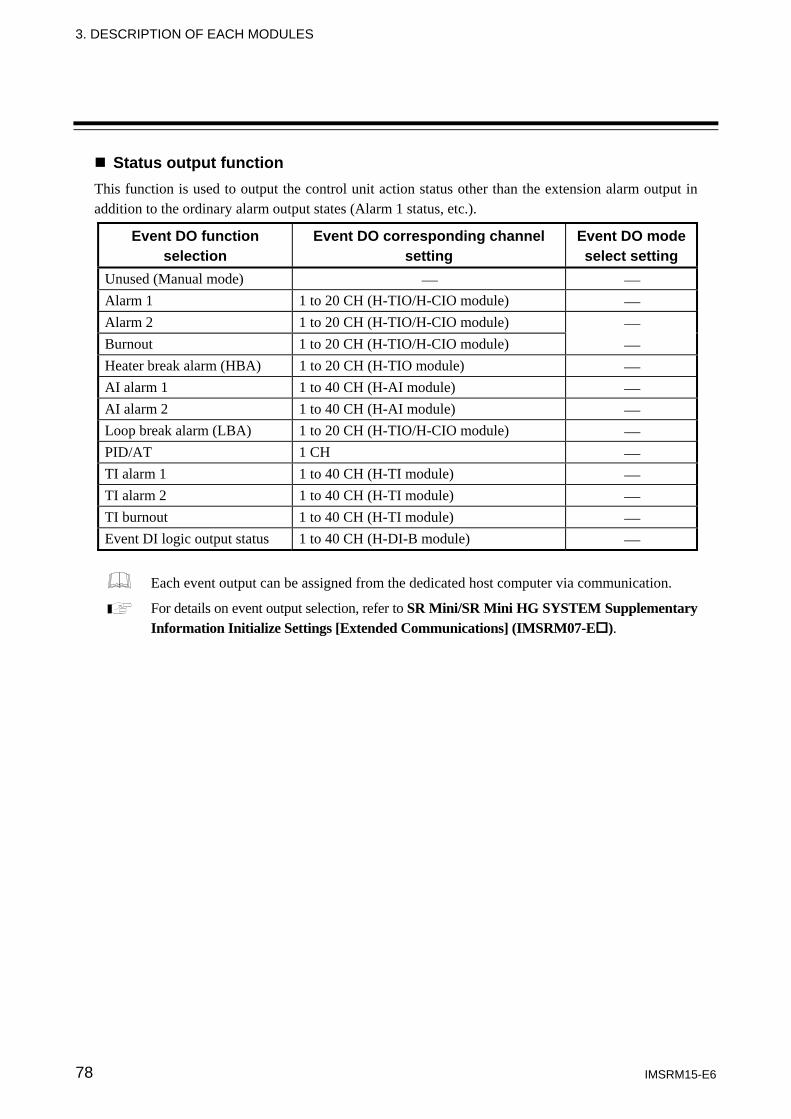
3. DESCRIPTION OF EACH MODULES
IMSRM15-E6 78
Status output function This function is used to output the control unit action status other than the extension alarm output in addition to the ordinary alarm output states (Alarm 1 status, etc.).
Event DO function selection
Event DO corresponding channel setting
Event DO mode select setting
Unused (Manual mode) ⎯ ⎯ Alarm 1 1 to 20 CH (H-TIO/H-CIO module) ⎯ Alarm 2 1 to 20 CH (H-TIO/H-CIO module) ⎯ Burnout 1 to 20 CH (H-TIO/H-CIO module) ⎯ Heater break alarm (HBA) 1 to 20 CH (H-TIO module) ⎯ AI alarm 1 1 to 40 CH (H-AI module) ⎯ AI alarm 2 1 to 40 CH (H-AI module) ⎯ Loop break alarm (LBA) 1 to 20 CH (H-TIO/H-CIO module) ⎯ PID/AT 1 CH ⎯ TI alarm 1 1 to 40 CH (H-TI module) ⎯ TI alarm 2 1 to 40 CH (H-TI module) ⎯ TI burnout 1 to 40 CH (H-TI module) ⎯ Event DI logic output status 1 to 40 CH (H-DI-B module) ⎯
Each event output can be assigned from the dedicated host computer via communication.
For details on event output selection, refer to SR Mini/SR Mini HG SYSTEM Supplementary Information Initialize Settings [Extended Communications] (IMSRM07-E ).
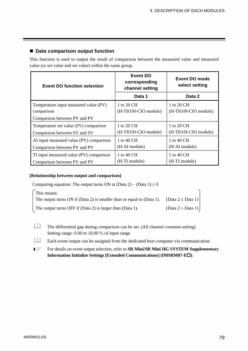
3. DESCRIPTION OF EACH MODULES
IMSRM15-E6 79
Data comparison output function This function is used to output the result of comparison between the measured value and measured value (or set value and set value) within the same group.
Event DO function selection
Event DO corresponding channel setting
Event DO mode select setting
Data 1 Data 2
Temperature input measured value (PV) comparison Comparison between PV and PV
1 to 20 CH (H-TIO/H-CIO module)
1 to 20 CH (H-TIO/H-CIO module)
Temperature set value (SV) comparison Comparison between SV and SV
1 to 20 CH (H-TIO/H-CIO module)
1 to 20 CH (H-TIO/H-CIO module)
AI input measured value (PV) comparison Comparison between PV and PV
1 to 40 CH (H-AI module)
1 to 40 CH (H-AI module)
TI input measured value (PV) comparison Comparison between PV and PV
1 to 40 CH (H-TI module)
1 to 40 CH (H-TI module)
[Relationship between output and comparison]
Computing equation: The output turns ON at (Data 2) − (Data 1) ≤ 0
This means: The output turns ON if (Data 2) is smaller than or equal to (Data 1). {Data 2 ≤ Data 1}
The output turns OFF if (Data 2) is larger than (Data 1). {Data 2 > Data 1}
The differential gap during comparison can be set. (All channel common setting) Setting range: 0.00 to 10.00 % of input range
Each event output can be assigned from the dedicated host computer via communication.
For details on event output selection, refer to SR Mini/SR Mini HG SYSTEM Supplementary Information Initialize Settings [Extended Communications] (IMSRM07-E ).
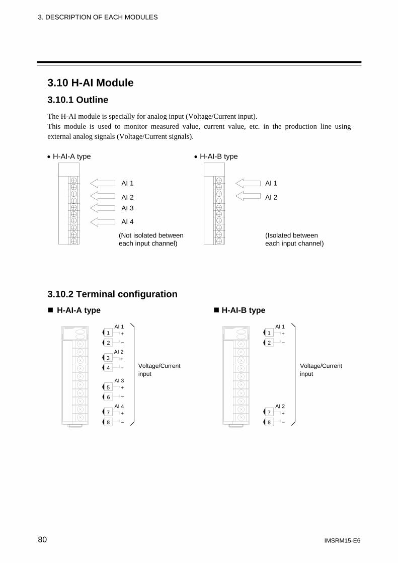
3. DESCRIPTION OF EACH MODULES
IMSRM15-E6 80
3.10 H-AI Module 3.10.1 Outline The H-AI module is specially for analog input (Voltage/Current input). This module is used to monitor measured value, current value, etc. in the production line using external analog signals (Voltage/Current signals). • H-AI-A type • H-AI-B type
AI 1
AI 2AI 3
AI 4
(Not isolated betweeneach input channel)
AI 1
AI 2
(Isolated betweeneach input channel)
3.10.2 Terminal configuration
H-AI-A type H-AI-B type
5
6
7
8
3
1
2
4
AI 1 + −
AI 2 + −
AI 3 + −
AI 4 + −
Voltage/Current input
7
8
1
2
AI 1 + −
AI 2 + −
Voltage/Current input
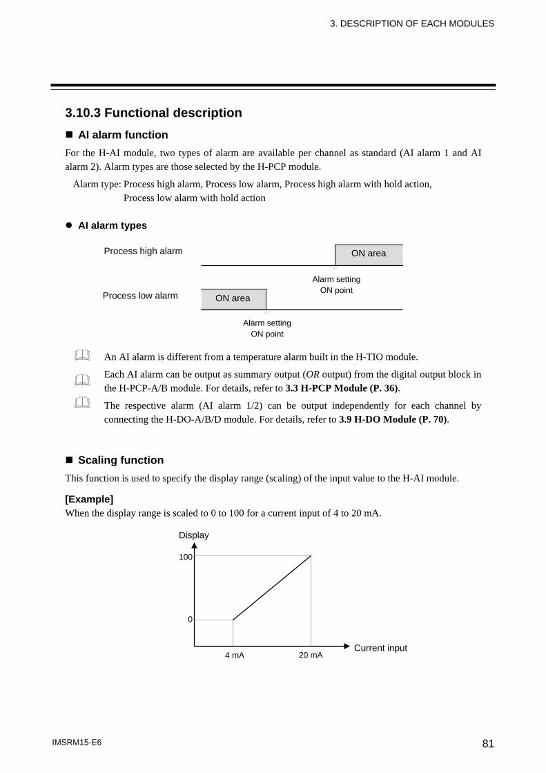
3. DESCRIPTION OF EACH MODULES
IMSRM15-E6 81
3.10.3 Functional description AI alarm function
For the H-AI module, two types of alarm are available per channel as standard (AI alarm 1 and AI alarm 2). Alarm types are those selected by the H-PCP module.
Alarm type: Process high alarm, Process low alarm, Process high alarm with hold action, Process low alarm with hold action
AI alarm types
An AI alarm is different from a temperature alarm built in the H-TIO module.
Each AI alarm can be output as summary output (OR output) from the digital output block in the H-PCP-A/B module. For details, refer to 3.3 H-PCP Module (P. 36).
The respective alarm (AI alarm 1/2) can be output independently for each channel by connecting the H-DO-A/B/D module. For details, refer to 3.9 H-DO Module (P. 70).
Scaling function This function is used to specify the display range (scaling) of the input value to the H-AI module. [Example] When the display range is scaled to 0 to 100 for a current input of 4 to 20 mA.
Display
Current input
100
0
4 mA 20 mA
ON area Process high alarm
Process low alarm ON area
Alarm settingON point
Alarm settingON point
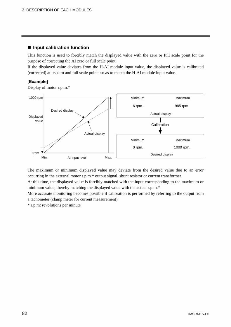
3. DESCRIPTION OF EACH MODULES
IMSRM15-E6 82
Input calibration function This function is used to forcibly match the displayed value with the zero or full scale point for the purpose of correcting the AI zero or full scale point. If the displayed value deviates from the H-AI module input value, the displayed value is calibrated (corrected) at its zero and full scale points so as to match the H-AI module input value. [Example] Display of motor r.p.m.*
Desired display
Actual display
AI input level
Displayedvalue
1000 rpm
0 rpmMin. Max.
Minimum Maximum
6 rpm. 985 rpm.
Actual display
0 rpm. 1000 rpm.
Desired display
Calibration
Minimum Maximum
The maximum or minimum displayed value may deviate from the desired value due to an error occurring in the external motor r.p.m.* output signal, shunt resistor or current transformer. At this time, the displayed value is forcibly matched with the input corresponding to the maximum or minimum value, thereby matching the displayed value with the actual r.p.m.* More accurate monitoring becomes possible if calibration is performed by referring to the output from a tachometer (clamp meter for current measurement). * r.p.m: revolutions per minute
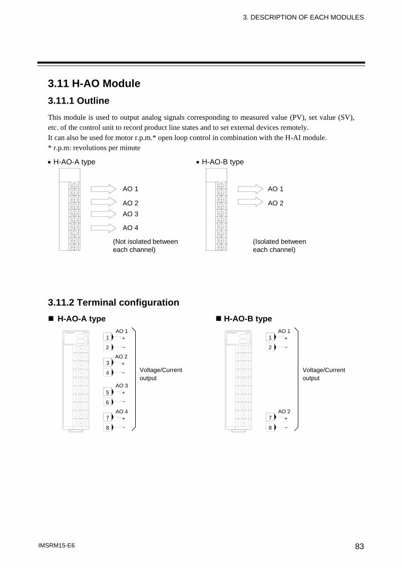
3. DESCRIPTION OF EACH MODULES
IMSRM15-E6 83
3.11 H-AO Module 3.11.1 Outline This module is used to output analog signals corresponding to measured value (PV), set value (SV), etc. of the control unit to record product line states and to set external devices remotely. It can also be used for motor r.p.m.* open loop control in combination with the H-AI module. * r.p.m: revolutions per minute
• H-AO-A type • H-AO-B type
AO 1
AO 2AO 3
AO 4
(Not isolated betweeneach channel)
AO 1
AO 2
(Isolated betweeneach channel)
3.11.2 Terminal configuration
H-AO-A type H-AO-B type
5
6
7
8
3
1
2
4
AO 1 + −
AO 2 + −
AO 3 + −
AO 4 + −
Voltage/Current output
7
8
1
2
AO 1 + −
AO 2 + −
Voltage/Current output
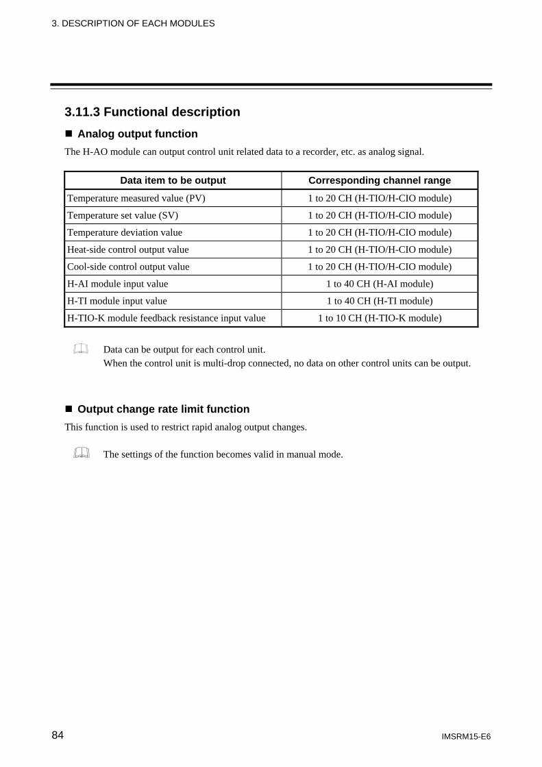
3. DESCRIPTION OF EACH MODULES
IMSRM15-E6 84
3.11.3 Functional description Analog output function
The H-AO module can output control unit related data to a recorder, etc. as analog signal.
Data item to be output Corresponding channel range
Temperature measured value (PV) 1 to 20 CH (H-TIO/H-CIO module)
Temperature set value (SV) 1 to 20 CH (H-TIO/H-CIO module)
Temperature deviation value 1 to 20 CH (H-TIO/H-CIO module)
Heat-side control output value 1 to 20 CH (H-TIO/H-CIO module)
Cool-side control output value 1 to 20 CH (H-TIO/H-CIO module)
H-AI module input value 1 to 40 CH (H-AI module)
H-TI module input value 1 to 40 CH (H-TI module)
H-TIO-K module feedback resistance input value 1 to 10 CH (H-TIO-K module)
Data can be output for each control unit. When the control unit is multi-drop connected, no data on other control units can be output.
Output change rate limit function This function is used to restrict rapid analog output changes.
The settings of the function becomes valid in manual mode.
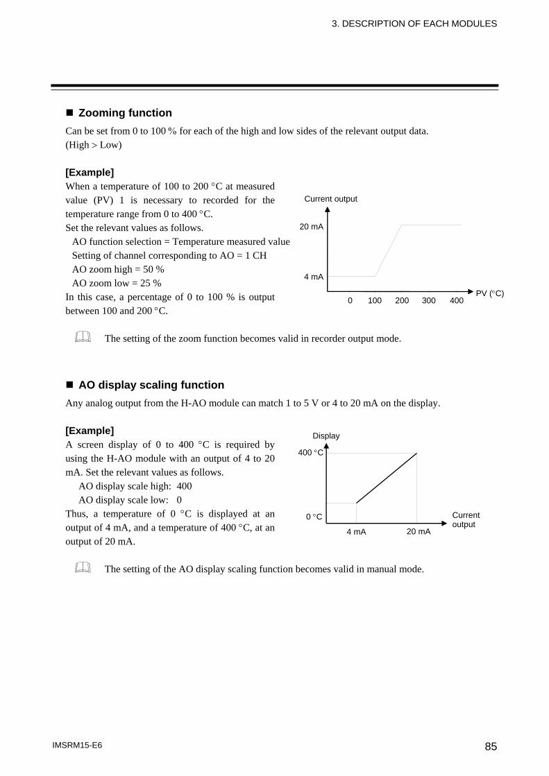
3. DESCRIPTION OF EACH MODULES
IMSRM15-E6 85
Zooming function Can be set from 0 to 100 % for each of the high and low sides of the relevant output data. (High > Low) [Example] When a temperature of 100 to 200 °C at measured value (PV) 1 is necessary to recorded for the temperature range from 0 to 400 °C. Set the relevant values as follows.
AO function selection = Temperature measured value Setting of channel corresponding to AO = 1 CH AO zoom high = 50 % AO zoom low = 25 %
In this case, a percentage of 0 to 100 % is output between 100 and 200 °C.
The setting of the zoom function becomes valid in recorder output mode.
AO display scaling function Any analog output from the H-AO module can match 1 to 5 V or 4 to 20 mA on the display. [Example] A screen display of 0 to 400 °C is required by using the H-AO module with an output of 4 to 20 mA. Set the relevant values as follows.
AO display scale high: 400 AO display scale low: 0
Thus, a temperature of 0 °C is displayed at an output of 4 mA, and a temperature of 400 °C, at an output of 20 mA.
The setting of the AO display scaling function becomes valid in manual mode.
Current output
Display
20 mA 4 mA
400 °C
0 °C
20 mA
Current output
PV (°C)0 100 200 300 400
4 mA
3. DESCRIPTION OF EACH MODULES
IMSRM15-E6 86
Output calibration function If some deviation occurs between the output value of the H-AO module and the actual operation of externally connected equipment, this function is used to forcibly correct the output signal of the H-AO modules at the zero and full scale points. For example, if the number of motor revolutions is set using the H-AO module with an output signal of 1 to 5 V, but the voltage value corresponding the actual number of revolutions is 0.1 V lower than the output value of the H-AO module, a correction of +2.5 % at the zero point changes the output value of the H-AO module to 1.1 to 5.1 V, thereby matching the AO displayed value to the actual number of revolutions.
If the zero point is corrected, the full scale point is also corrected by the same amount. If the full scale point is corrected, no zero point is corrected.
IMSRM15-E6 87
4. MOUNTING
4.1 Mounting Cautions (1) This instrument is intended to be used under the following environmental conditions.
(IEC61010-1) [OVERVOLTAGE CATEGORY II, POLLUTION DEGREE 2] (2) Use this instrument within the following environment conditions: • Allowable ambient temperature: 0 to 50 °C • Allowable ambient humidity: 45 to 85 % RH (Absolute humidity: MAX.W.C 29.3 g/m3 dry air at 101.3 kPa) • Installation environment conditions: Indoor use Altitude up to 2000 m
(3) Avoid the following conditions when selecting the mounting location: • Rapid changes in ambient temperature which may cause condensation. • Corrosive or inflammable gases. • Direct vibration or shock to the mainframe. • Water, oil, chemicals, vapor or steam splashes. • Excessive dust, salt or iron particles. • Excessive induction noise, static electricity, magnetic fields or noise. • Direct air flow from an air conditioner. • Exposure to direct sunlight. • Excessive heat accumulation.
(4) In case this instrument is connected to a supply by means of a permanent connection a switch or
circuit-breaker shall be included in the installation. This shall be in close proximity to the equipment and within easy reach of the operator. It shall be marked as the disconnecting device for the equipment.
To prevent electric shock or instrument failure, always turn off the power before mounting or removing the instrument.
WARNING!
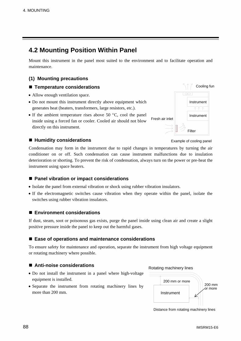
4. MOUNTING
IMSRM15-E6 88
4.2 Mounting Position Within Panel Mount this instrument in the panel most suited to the environment and to facilitate operation and maintenance. (1) Mounting precautions
Temperature considerations • Allow enough ventilation space. • Do not mount this instrument directly above equipment which
generates heat (heaters, transformers, large resistors, etc.). • If the ambient temperature rises above 50 °C, cool the panel
inside using a forced fan or cooler. Cooled air should not blow directly on this instrument.
Humidity considerations Condensation may form in the instrument due to rapid changes in temperatures by turning the air conditioner on or off. Such condensation can cause instrument malfunctions due to insulation deterioration or shorting. To prevent the risk of condensation, always turn on the power or pre-heat the instrument using space heaters.
Panel vibration or impact considerations • Isolate the panel from external vibration or shock using rubber vibration insulators. • If the electromagnetic switches cause vibration when they operate within the panel, isolate the
switches using rubber vibration insulators.
Environment considerations If dust, steam, soot or poisonous gas exists, purge the panel inside using clean air and create a slight positive pressure inside the panel to keep out the harmful gases.
Ease of operations and maintenance considerations To ensure safety for maintenance and operation, separate the instrument from high voltage equipment or rotating machinery where possible.
Anti-noise considerations • Do not install the instrument in a panel where high-voltage
equipment is installed. • Separate the instrument from rotating machinery lines by
more than 200 mm.
Distance from rotating machinery lines
Instrument
Rotating machinery lines
200 mm or more 200 mm or more
Cooling fun
Fresh air inlet
Filter
Instrument
Example of cooling panel
Instrument
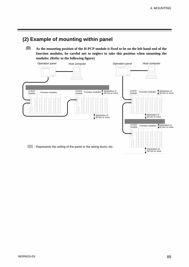
4. MOUNTING
IMSRM15-E6 89
(2) Example of mounting within panel
As the mounting position of the H-PCP module is fixed to be on the left hand end of the function modules, be careful not to neglect to take this position when mounting the modules. (Refer to the following figure)
Operation panel Operation panel Host computer Host computer
H-PCP module Function modules
Separation of 50 mm or more
: Represents the ceiling of the panel or the wiring ducts, etc.
H-PCPmodule
H-PCP module
H-PCP module
Function modules Function modules
Function modules
Separation of 50 mm or more
Separation of 50 mm or more
Separation of 50 mm or more
Separation of 50 mm or more
Separation of 50 mm or more
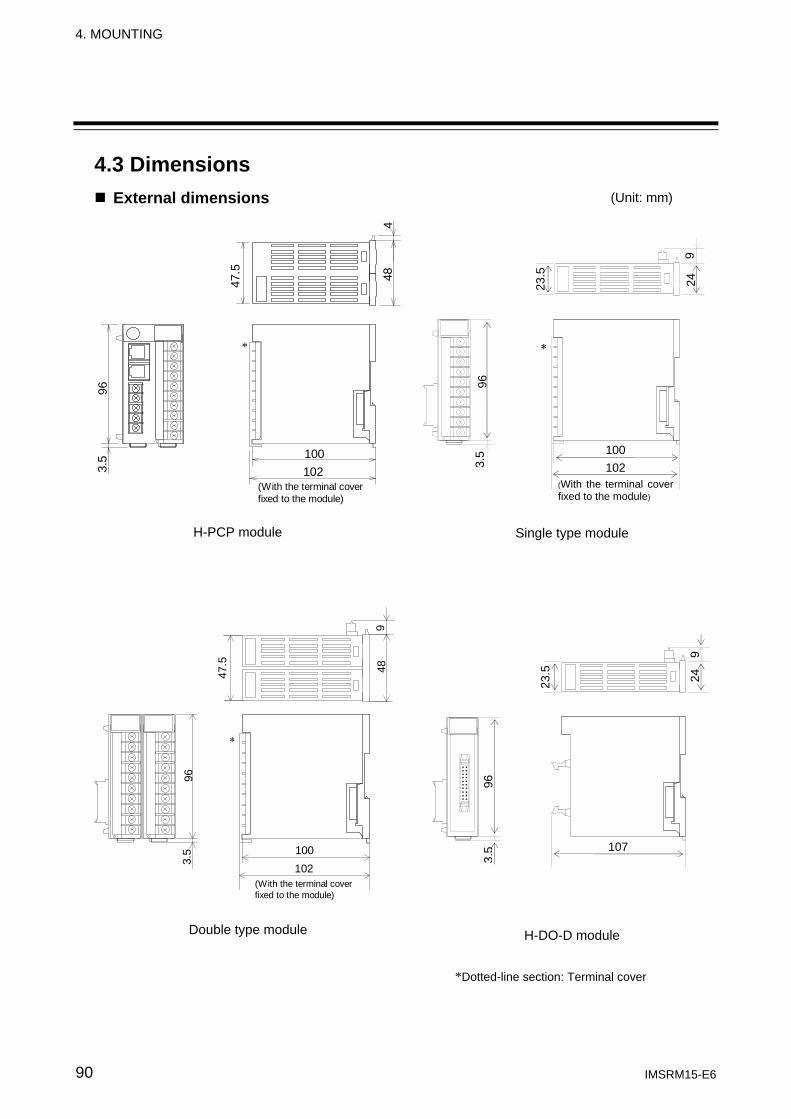
4. MOUNTING
IMSRM15-E6 90
4.3 Dimensions External dimensions
963.
5 100102
44847.5
(With the terminal coverfixed to the module)
*
47.5
948
963.
5 100102
(With the terminal coverfixed to the module)
∗
H-PCP module
(Unit: mm)
23.5
9 24
96
3.5 100
102 (With the terminal cover fixed to the module)
∗
Single type module
*Dotted-line section: Terminal cover
Double type module H-DO-D module
23.5
9 24
96
3.5 107
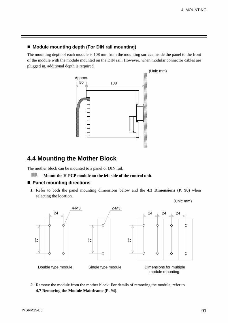
4. MOUNTING
IMSRM15-E6 91
Module mounting depth (For DIN rail mounting) The mounting depth of each module is 108 mm from the mounting surface inside the panel to the front of the module with the module mounted on the DIN rail. However, when modular connector cables are plugged in, additional depth is required. 4.4 Mounting the Mother Block The mother block can be mounted to a panel or DIN rail.
Mount the H-PCP module on the left side of the control unit.
Panel mounting directions 1. Refer to both the panel mounting dimensions below and the 4.3 Dimensions (P. 90) when
selecting the location.
4-M324 24
77
24 24
77
Double type module Dimensions for multiplemodule mounting.
(Unit: mm)
Single type module
2-M3
77
2. Remove the module from the mother block. For details of removing the module, refer to 4.7 Removing the Module Mainframe (P. 94).
(Unit: mm)
Approx. 50 108
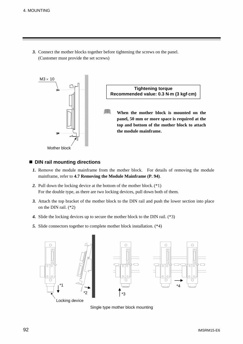
4. MOUNTING
IMSRM15-E6 92
3. Connect the mother blocks together before tightening the screws on the panel. (Customer must provide the set screws)
DIN rail mounting directions 1. Remove the module mainframe from the mother block. For details of removing the module
mainframe, refer to 4.7 Removing the Module Mainframe (P. 94).
2. Pull down the locking device at the bottom of the mother block. (*1) For the double type, as there are two locking devices, pull down both of them.
3. Attach the top bracket of the mother block to the DIN rail and push the lower section into place
on the DIN rail. (*2)
4. Slide the locking devices up to secure the mother block to the DIN rail. (*3)
5. Slide connectors together to complete mother block installation. (*4)
Locking device
*1
*2 *3
*4
Single type mother block mounting
Tightening torque Recommended value: 0.3 N⋅m (3 kgf⋅cm)
When the mother block is mounted on the panel, 50 mm or more space is required at the top and bottom of the mother block to attach the module mainframe.
M3 × 10
Mother block
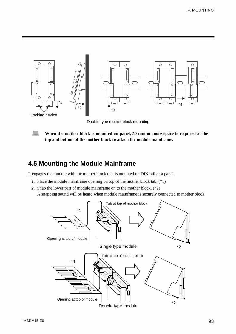
4. MOUNTING
IMSRM15-E6 93
*1
Locking device
*2 *3*4
Double type mother block mounting
When the mother block is mounted on panel, 50 mm or more space is required at the top and bottom of the mother block to attach the module mainframe.
4.5 Mounting the Module Mainframe It engages the module with the mother block that is mounted on DIN rail or a panel.
1. Place the module mainframe opening on top of the mother block tab. (*1) 2. Snap the lower part of module mainframe on to the mother block. (*2)
A snapping sound will be heard when module mainframe is securely connected to mother block.
Single type module
Double type module
Tab at top of mother block
Opening at top of module
*2
*1
*2
*1 Tab at top of mother block
Opening at top of module
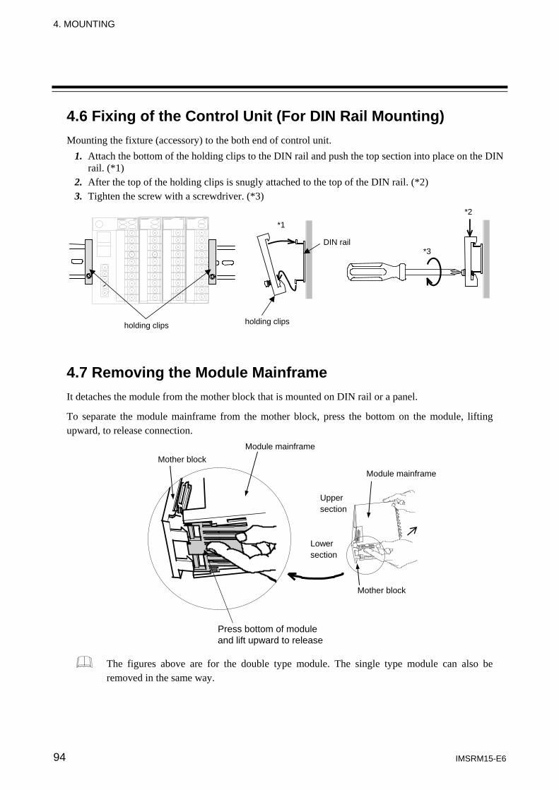
4. MOUNTING
IMSRM15-E6 94
4.6 Fixing of the Control Unit (For DIN Rail Mounting) Mounting the fixture (accessory) to the both end of control unit.
1. Attach the bottom of the holding clips to the DIN rail and push the top section into place on the DIN rail. (*1)
2. After the top of the holding clips is snugly attached to the top of the DIN rail. (*2) 3. Tighten the screw with a screwdriver. (*3)
*1
holding clips
*3
*2
DIN rail
holding clips
4.7 Removing the Module Mainframe It detaches the module from the mother block that is mounted on DIN rail or a panel.
To separate the module mainframe from the mother block, press the bottom on the module, lifting upward, to release connection.
The figures above are for the double type module. The single type module can also be removed in the same way.
Mother block Module mainframe
Upper section
Mother block
Module mainframe
Lower section
Press bottom of module and lift upward to release
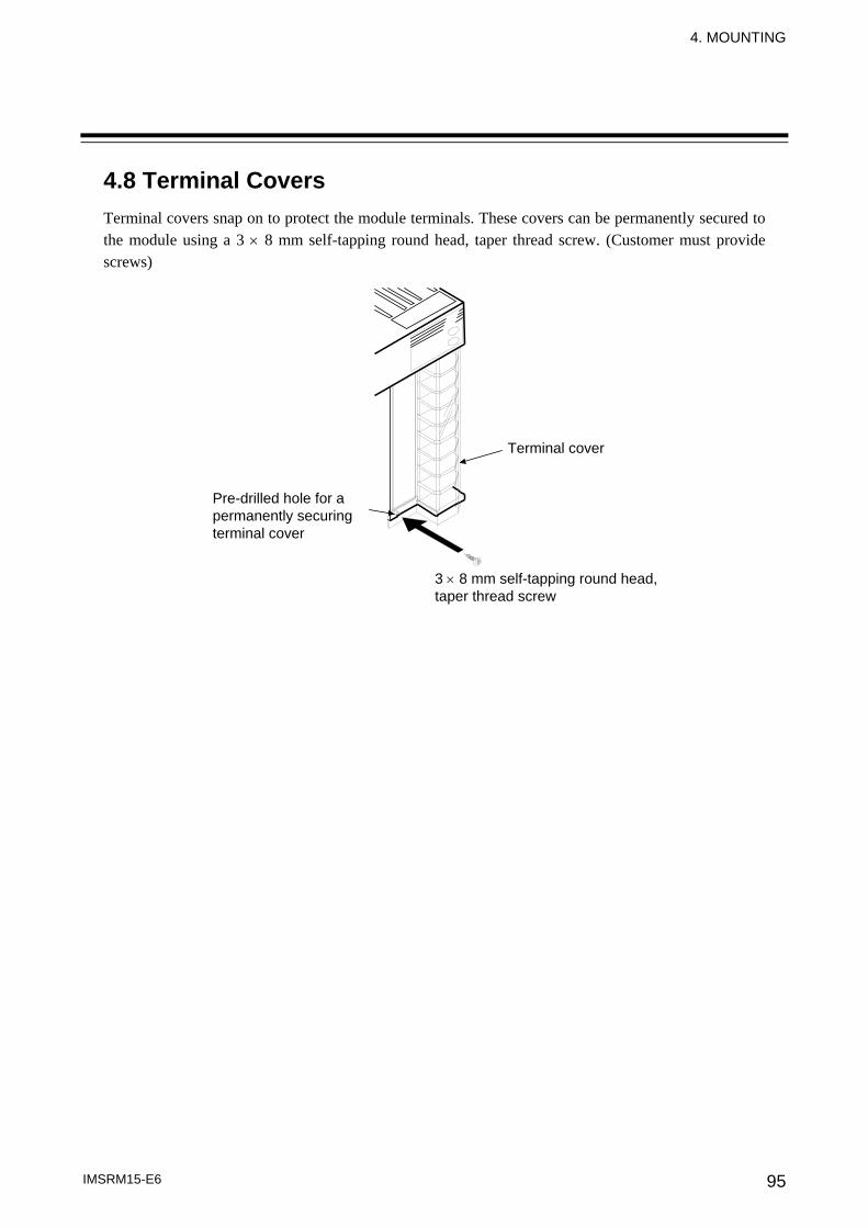
4. MOUNTING
IMSRM15-E6 95
4.8 Terminal Covers Terminal covers snap on to protect the module terminals. These covers can be permanently secured to the module using a 3 × 8 mm self-tapping round head, taper thread screw. (Customer must provide screws)
3 × 8 mm self-tapping round head, taper thread screw
Terminal cover
Pre-drilled hole for a permanently securing terminal cover
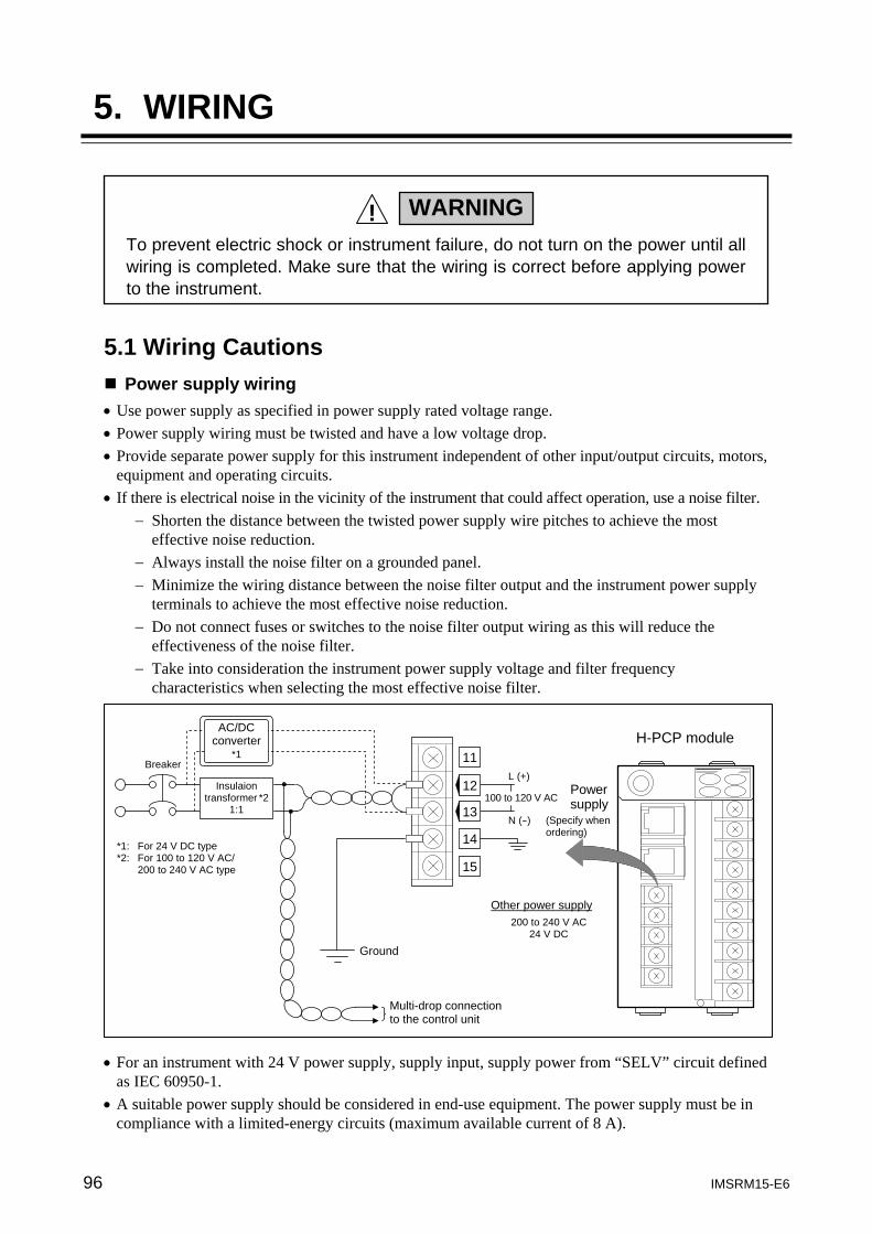
96 IMSRM15-E6
5. WIRING
5.1 Wiring Cautions
Power supply wiring • Use power supply as specified in power supply rated voltage range. • Power supply wiring must be twisted and have a low voltage drop. • Provide separate power supply for this instrument independent of other input/output circuits, motors,
equipment and operating circuits. • If there is electrical noise in the vicinity of the instrument that could affect operation, use a noise filter.
− Shorten the distance between the twisted power supply wire pitches to achieve the most effective noise reduction.
− Always install the noise filter on a grounded panel. − Minimize the wiring distance between the noise filter output and the instrument power supply
terminals to achieve the most effective noise reduction. − Do not connect fuses or switches to the noise filter output wiring as this will reduce the
effectiveness of the noise filter. − Take into consideration the instrument power supply voltage and filter frequency
characteristics when selecting the most effective noise filter. • For an instrument with 24 V power supply, supply input, supply power from “SELV” circuit defined
as IEC 60950-1. • A suitable power supply should be considered in end-use equipment. The power supply must be in
compliance with a limited-energy circuits (maximum available current of 8 A).
To prevent electric shock or instrument failure, do not turn on the power until all wiring is completed. Make sure that the wiring is correct before applying power to the instrument.
WARNING!
H-PCP module
*1: For 24 V DC type *2: For 100 to 120 V AC/ 200 to 240 V AC type
100 to 120 V AC
L (+)
N (-)
14
Breaker
13
12
Ground
Multi-drop connection to the control unit
Power supply
Other power supply 200 to 240 V AC
24 V DC
Insulaion transformer *2
1:1
AC/DC converter
*1
(Specify when ordering)
15
11
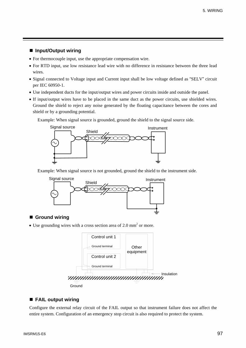
5. WIRING
IMSRM15-E6 97
Input/Output wiring • For thermocouple input, use the appropriate compensation wire. • For RTD input, use low resistance lead wire with no difference in resistance between the three lead
wires. • Signal connected to Voltage input and Current input shall be low voltage defined as “SELV” circuit
per IEC 60950-1. • Use independent ducts for the input/output wires and power circuits inside and outside the panel. • If input/output wires have to be placed in the same duct as the power circuits, use shielded wires.
Ground the shield to reject any noise generated by the floating capacitance between the cores and shield or by a grounding potential.
Example: When signal source is grounded, ground the shield to the signal source side.
Example: When signal source is not grounded, ground the shield to the instrument side.
Ground wiring • Use grounding wires with a cross section area of 2.0 mm2 or more.
FAIL output wiring Configure the external relay circuit of the FAIL output so that instrument failure does not affect the entire system. Configuration of an emergency stop circuit is also required to protect the system.
Shield Signal source Instrument
Shield Signal source Instrument
Insulation
Other equipment
Control unit 1
Ground terminal
Ground terminal
Ground
Control unit 2
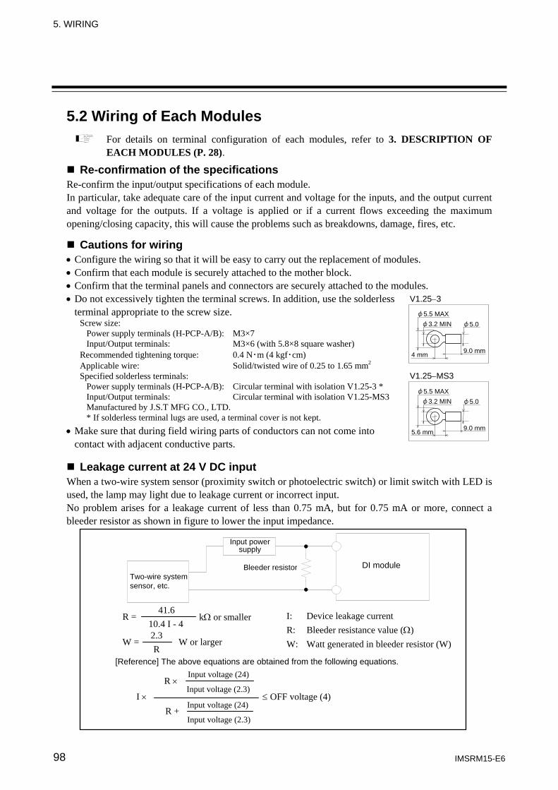
5. WIRING
IMSRM15-E6 98
5.2 Wiring of Each Modules For details on terminal configuration of each modules, refer to 3. DESCRIPTION OF EACH MODULES (P. 28).
Re-confirmation of the specifications Re-confirm the input/output specifications of each module. In particular, take adequate care of the input current and voltage for the inputs, and the output current and voltage for the outputs. If a voltage is applied or if a current flows exceeding the maximum opening/closing capacity, this will cause the problems such as breakdowns, damage, fires, etc.
Cautions for wiring • Configure the wiring so that it will be easy to carry out the replacement of modules. • Confirm that each module is securely attached to the mother block. • Confirm that the terminal panels and connectors are securely attached to the modules. • Do not excessively tighten the terminal screws. In addition, use the solderless
terminal appropriate to the screw size. Screw size: Power supply terminals (H-PCP-A/B): M3×7 Input/Output terminals: M3×6 (with 5.8×8 square washer) Recommended tightening torque: 0.4 N・m (4 kgf・cm) Applicable wire: Solid/twisted wire of 0.25 to 1.65 mm2 Specified solderless terminals: Power supply terminals (H-PCP-A/B): Circular terminal with isolation V1.25-3 * Input/Output terminals: Circular terminal with isolation V1.25-MS3 Manufactured by J.S.T MFG CO., LTD. * If solderless terminal lugs are used, a terminal cover is not kept.
• Make sure that during field wiring parts of conductors can not come into contact with adjacent conductive parts.
Leakage current at 24 V DC input
When a two-wire system sensor (proximity switch or photoelectric switch) or limit switch with LED is used, the lamp may light due to leakage current or incorrect input. No problem arises for a leakage current of less than 0.75 mA, but for 0.75 mA or more, connect a bleeder resistor as shown in figure to lower the input impedance.
Two-wire system sensor, etc.
Input power supply
Bleeder resistor DI module
41.6 10.4 I - 4
R = kΩ or smaller
2.3 R
W = W or larger
I: Device leakage current R: Bleeder resistance value (Ω) W: Watt generated in bleeder resistor (W)
[Reference] The above equations are obtained from the following equations. Input voltage (24)
R × Input voltage (2.3)
Input voltage (24)R +
Input voltage (2.3)
I × ≤ OFF voltage (4)
V1.25−MS3
V1.25−3
φ3.2 MIN φ5.5 MAX
φ5.0
4 mm 9.0 mm
φ3.2 MIN φ5.5 MAX
φ5.0
5.6 mm 9.0 mm
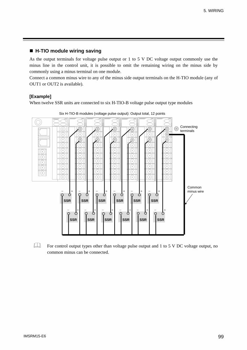
5. WIRING
IMSRM15-E6 99
H-TIO module wiring saving As the output terminals for voltage pulse output or 1 to 5 V DC voltage output commonly use the minus line in the control unit, it is possible to omit the remaining wiring on the minus side by commonly using a minus terminal on one module. Connect a common minus wire to any of the minus side output terminals on the H-TIO module (any of OUT1 or OUT2 is available). [Example] When twelve SSR units are connected to six H-TIO-B voltage pulse output type modules
Connecting terminals
Common minus wire
SSR SSR SSR SSR SSR SSR
SSR SSR SSR SSR SSR SSR
− + − + − + − + − + − +
− + − + − + − + − + − +
Six H-TIO-B modules (voltage pulse output): Output total, 12 points
For control output types other than voltage pulse output and 1 to 5 V DC voltage output, no common minus can be connected.
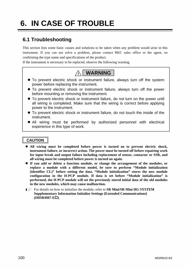
100 IMSRM15-E6
6. IN CASE OF TROUBLE
6.1 Troubleshooting This section lists some basic causes and solutions to be taken when any problem would arise in this instrument. If you can not solve a problem, please contact RKC sales office or the agent, on confirming the type name and specifications of the product. If the instrument is necessary to be replaced, observe the following warning.
All wiring must be completed before power is turned on to prevent electric shock,
instrument failure, or incorrect action. The power must be turned off before repairing work for input break and output failure including replacement of sensor, contactor or SSR, and all wiring must be completed before power is turned on again.
If you add or delete a function module, or change the arrangement of the modules, or replace a module with a different model, be sure to perform “Module initialization (identifier CL)” before setting the data. “Module initialization” stores the new module configuration in the H-PCP module. If data is set before “Module initialization” is performed, the H-PCP module will set the previously stored initial data of the old modules in the new modules, which may cause malfunction.
For details on how to initialize the module, refer to SR Mini/SR Mini HG SYSTEM Supplementary Information Initialize Settings [Extended Communications] (IMSRM07-E ).
CAUTION
To prevent electric shock or instrument failure, always turn off the system power before replacing the instrument.
To prevent electric shock or instrument failure, always turn off the power before mounting or removing the instrument.
To prevent electric shock or instrument failure, do not turn on the power until all wiring is completed. Make sure that the wiring is correct before applying power to the instrument.
To prevent electric shock or instrument failure, do not touch the inside of the instrument.
All wiring must be performed by authorized personnel with electrical experience in this type of work.
WARNING!
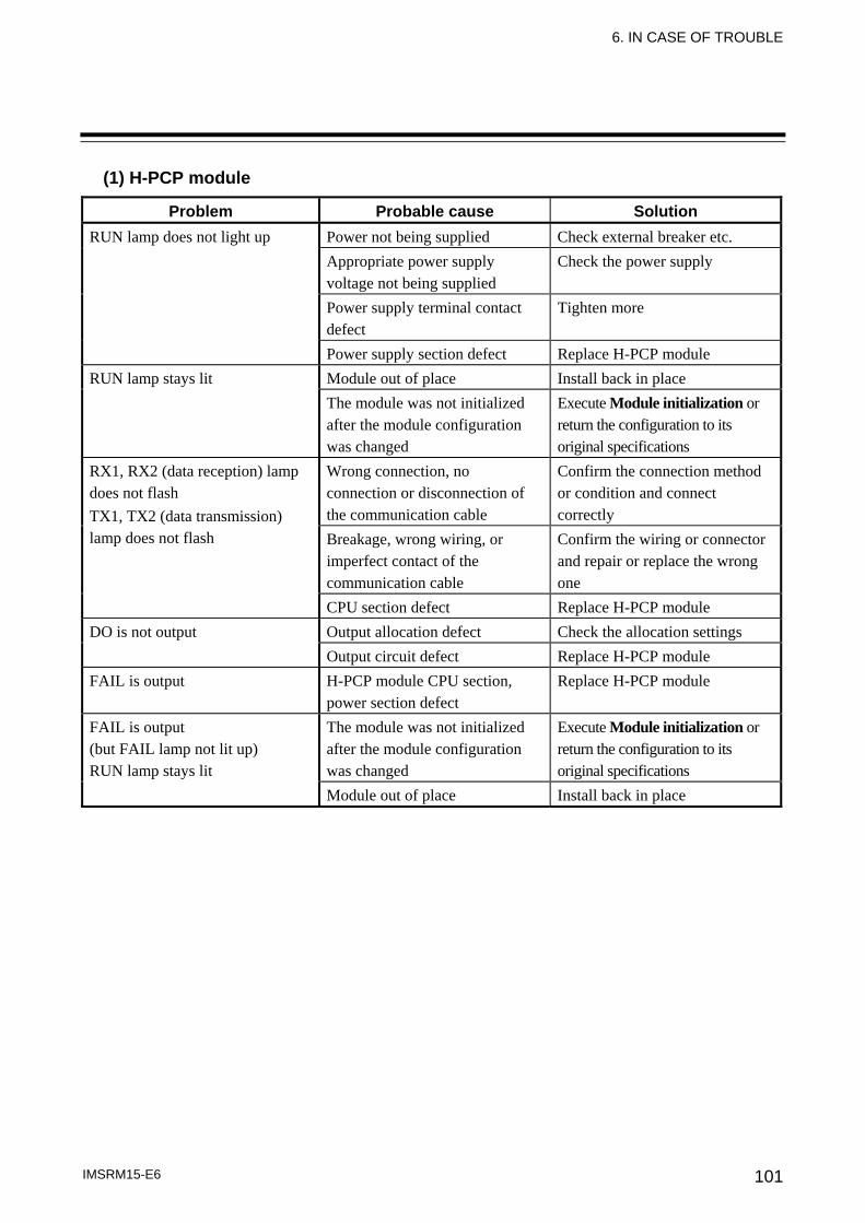
6. IN CASE OF TROUBLE
IMSRM15-E6 101
(1) H-PCP module
Problem Probable cause Solution RUN lamp does not light up Power not being supplied Check external breaker etc.
Appropriate power supply voltage not being supplied
Check the power supply
Power supply terminal contact defect
Tighten more
Power supply section defect Replace H-PCP module RUN lamp stays lit Module out of place Install back in place
The module was not initialized after the module configuration was changed
Execute Module initialization or return the configuration to its original specifications
RX1, RX2 (data reception) lamp does not flash TX1, TX2 (data transmission) lamp does not flash
Wrong connection, no connection or disconnection of the communication cable
Confirm the connection method or condition and connect correctly
Breakage, wrong wiring, or imperfect contact of the communication cable
Confirm the wiring or connector and repair or replace the wrong one
CPU section defect Replace H-PCP module DO is not output Output allocation defect Check the allocation settings
Output circuit defect Replace H-PCP module FAIL is output H-PCP module CPU section,
power section defect Replace H-PCP module
FAIL is output (but FAIL lamp not lit up) RUN lamp stays lit
The module was not initialized after the module configuration was changed
Execute Module initialization or return the configuration to its original specifications
Module out of place Install back in place
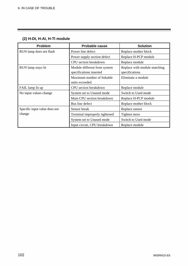
6. IN CASE OF TROUBLE
IMSRM15-E6 102
(2) H-DI, H-AI, H-TI module
Problem Probable cause Solution RUN lamp does not flash Power line defect Replace mother block
Power supply section defect Replace H-PCP module CPU section breakdown Replace module
RUN lamp stays lit Module different from system specifications inserted
Replace with module matching specifications
Maximum number of linkable units exceeded
Eliminate a module
FAIL lamp lit up CPU section breakdown Replace module No input values change System set to Unused mode Switch to Used mode
Main CPU section breakdown Replace H-PCP module Bus line defect Replace mother block
Specific input value does not change
Sensor break Replace sensor Terminal improperly tightened Tighten more System set to Unused mode Switch to Used mode Input circuit, CPU breakdown Replace module
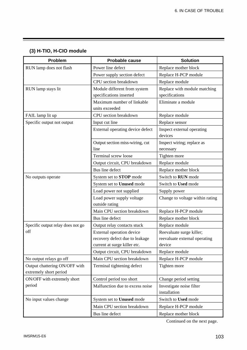
6. IN CASE OF TROUBLE
IMSRM15-E6 103
(3) H-TIO, H-CIO module
Problem Probable cause Solution RUN lamp does not flash Power line defect Replace mother block
Power supply section defect Replace H-PCP module CPU section breakdown Replace module
RUN lamp stays lit Module different from system specifications inserted
Replace with module matching specifications
Maximum number of linkable units exceeded
Eliminate a module
FAIL lamp lit up CPU section breakdown Replace module Specific output not output Input cut line Replace sensor
External operating device defect Inspect external operating devices
Output section miss-wiring, cut line
Inspect wiring; replace as necessary
Terminal screw loose Tighten more Output circuit, CPU breakdown Replace module Bus line defect Replace mother block
No outputs operate System set to STOP mode Switch to RUN mode System set to Unused mode Switch to Used mode Load power not supplied Supply power Load power supply voltage outside rating
Change to voltage within rating
Main CPU section breakdown Replace H-PCP module Bus line defect Replace mother block
Specific output relay does not go off
Output relay contacts stuck Replace module External operation device recovery defect due to leakage current at surge killer etc.
Reevaluate surge killer; reevaluate external operating device
Output circuit, CPU breakdown Replace module No output relays go off Main CPU section breakdown Replace H-PCP module Output chattering ON/OFF with extremely short period
Terminal tightening defect Tighten more
ON/OFF with extremely short period
Control period too short Change period setting Malfunction due to excess noise Investigate noise filter
installation No input values change System set to Unused mode Switch to Used mode
Main CPU section breakdown Replace H-PCP module Bus line defect Replace mother block
Continued on the next page.
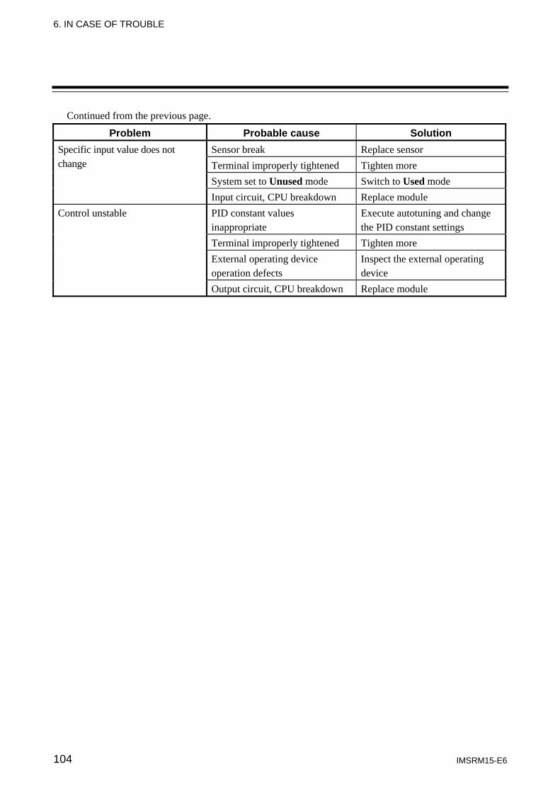
6. IN CASE OF TROUBLE
IMSRM15-E6 104
Continued from the previous page.
Problem Probable cause Solution Specific input value does not change
Sensor break Replace sensor Terminal improperly tightened Tighten more System set to Unused mode Switch to Used mode Input circuit, CPU breakdown Replace module
Control unstable PID constant values inappropriate
Execute autotuning and change the PID constant settings
Terminal improperly tightened Tighten more External operating device operation defects
Inspect the external operating device
Output circuit, CPU breakdown Replace module
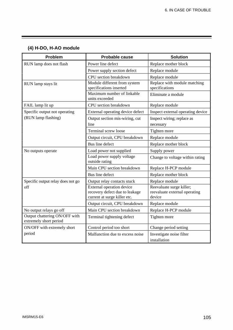
6. IN CASE OF TROUBLE
IMSRM15-E6 105
(4) H-DO, H-AO module
Problem Probable cause Solution RUN lamp does not flash Power line defect Replace mother block
Power supply section defect Replace module CPU section breakdown Replace module
RUN lamp stays lit Module different from system specifications inserted
Replace with module matching specifications
Maximum number of linkable units exceeded
Eliminate a module
FAIL lamp lit up CPU section breakdown Replace module Specific output not operating (RUN lamp flashing)
External operating device defect Inspect external operating deviceOutput section mis-wiring, cut line
Inspect wiring; replace as necessary
Terminal screw loose Tighten more Output circuit, CPU breakdown Replace module Bus line defect Replace mother block
No outputs operate Load power not supplied Supply power Load power supply voltage outside rating
Change to voltage within rating
Main CPU section breakdown Replace H-PCP module Bus line defect Replace mother block
Specific output relay does not go off
Output relay contacts stuck Replace module External operation device recovery defect due to leakage current at surge killer etc.
Reevaluate surge killer; reevaluate external operating device
Output circuit, CPU breakdown Replace module No output relays go off Main CPU section breakdown Replace H-PCP module Output chattering ON/OFF with extremely short period
Terminal tightening defect Tighten more
ON/OFF with extremely short period
Control period too short Change period setting Malfunction due to excess noise Investigate noise filter
installation
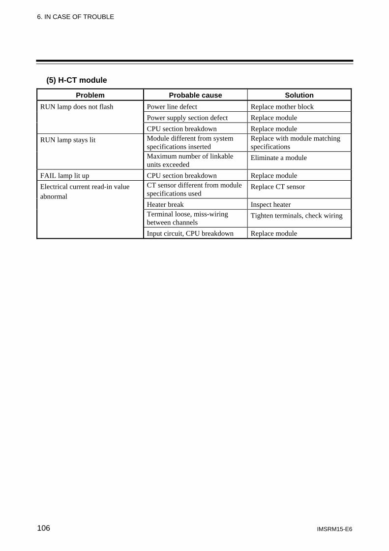
6. IN CASE OF TROUBLE
IMSRM15-E6 106
(5) H-CT module
Problem Probable cause Solution RUN lamp does not flash Power line defect Replace mother block
Power supply section defect Replace module CPU section breakdown Replace module
RUN lamp stays lit Module different from system specifications inserted
Replace with module matching specifications
Maximum number of linkable units exceeded
Eliminate a module
FAIL lamp lit up CPU section breakdown Replace module Electrical current read-in value abnormal
CT sensor different from module specifications used
Replace CT sensor
Heater break Inspect heater Terminal loose, miss-wiring between channels
Tighten terminals, check wiring
Input circuit, CPU breakdown Replace module
6. IN CASE OF TROUBLE
IMSRM15-E6 107
6.2 Module Replacement Procedure H-PCP module replacement
As all data on PID constants, alarm set values, etc. is managed by the H-PCP module, it is necessary to re-enter and re-set all data when the H-PCP module is replaced. However, re-entry and re-set are not required in the following cases. • When data backup software is operating in the module by the external host
computer. • When it is set on the operation panel so that data on the operation panel side is
transferred to the control unit side when the power is turned on again. To remove the H-PCP module from the mother block, follow the reverse order of module mounting.
Replacement procedure 1. Turn off the power to the control unit. 2. Remove the module mainframe from the mother block. 3. Mount the normal module mainframe.
A snapping sound will be heard when module mainframe is securely connected to mother block. 4. Turn on the power to the control unit. 5. Replacement end
For details on mounting/removing the module mainframe, refer to the 4.5 Mounting the Module Mainframe (P. 93) and 4.7 Removing the Module Mainframe (P. 94).
6. IN CASE OF TROUBLE
IMSRM15-E6 108
Function module replacement
If you add or delete a function module, or change the arrangement of the modules, or replace a module with a different model, be sure to perform “Module initialization (identifier CL)” before setting the data. “Module initialization” stores the new module configuration in the H-PCP module. If data is set before “Module initialization” is performed, the H-PCP module will set the previously stored initial data of the old modules in the new modules, which may cause malfunction.
For details on how to initialize the module, refer to SR Mini/SR Mini HG SYSTEM Supplementary Information Initialize Settings [Extended Communications] (IMSRM07-E ).
When replacing the function module with the same model code, initialization of a module is unnecessary. Before replacing the present module with a new one, set channel operation mode used in the former to Unused mode. Be careful not to remove the module without first setting this channel to the Unused mode, otherwise a failure will be output from the H-PCP module. However, the FAIL lamp of the H-PCP module will not light at this time.
In this instrument, even if a function module is detached, the operation of the other channels can be continued as before. After mounting the normally operating module, set the channel used by this module to the Normal mode. This operation causes the previously used temperature set value, PID constants, etc. to be transmitted from the H-PCP module, and it is possible to use the module as before.
To remove the function module from the mother block, follow the reverse order of module mounting.
Replacement procedure (When replacing the function module with the same model code) 1. Switch the used channel of the faulty module to Unused mode. 2. Turn off the power to the control unit. 3. Remove the module mainframe from the mother block. 4. Mount the normal module mainframe. 5. Turn on the power to the control unit. 6. Switch the used channel to Normal mode.
This operation causes the previously used temperature set value, PID constants, etc. to be transmitted from the H-PCP module, and it is possible to use the module as before.
7. Replacement end
For details on mounting/removing the module mainframe, refer to the 4.5 Mounting the Module Mainframe (P. 93) and 4.7 Removing the Module Mainframe (P. 94).
CAUTION
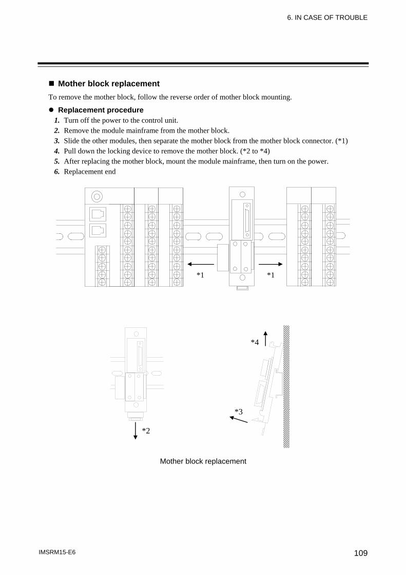
6. IN CASE OF TROUBLE
IMSRM15-E6 109
Mother block replacement To remove the mother block, follow the reverse order of mother block mounting.
Replacement procedure 1. Turn off the power to the control unit. 2. Remove the module mainframe from the mother block. 3. Slide the other modules, then separate the mother block from the mother block connector. (*1) 4. Pull down the locking device to remove the mother block. (*2 to *4) 5. After replacing the mother block, mount the module mainframe, then turn on the power. 6. Replacement end
*1 *1
Mother block replacement
*2
*3
*4
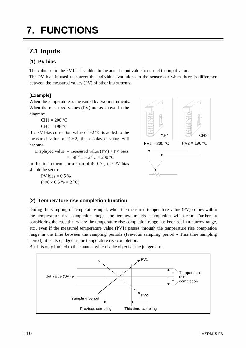
110 IMSRM15-E6
7. FUNCTIONS
7.1 Inputs (1) PV bias
The value set in the PV bias is added to the actual input value to correct the input value. The PV bias is used to correct the individual variations in the sensors or when there is difference between the measured values (PV) of other instruments. [Example] When the temperature is measured by two instruments. When the measured values (PV) are as shown in the diagram:
CH1 = 200 °C CH2 = 198 °C
If a PV bias correction value of +2 °C is added to the measured value of CH2, the displayed value will become:
Displayed value = measured value (PV) + PV bias = 198 °C + 2 °C = 200 °C
In this instrument, for a span of 400 °C, the PV bias should be set to:
PV bias = 0.5 % (400 × 0.5 % = 2 °C)
(2) Temperature rise completion function
During the sampling of temperature input, when the measured temperature value (PV) comes within the temperature rise completion range, the temperature rise completion will occur. Further in considering the case that where the temperature rise completion range has been set in a narrow range, etc., even if the measured temperature value (PV1) passes through the temperature rise completion range in the time between the sampling periods (Previous sampling period - This time sampling period), it is also judged as the temperature rise completion. But it is only limited to the channel which is the object of the judgement.
PV1
PV2Sampling period
Previous sampling This time sampling
Set value (SV)Temperaturerisecompletion
+
−
CH1 CH2
PV1 = 200 °C PV2 = 198 °C
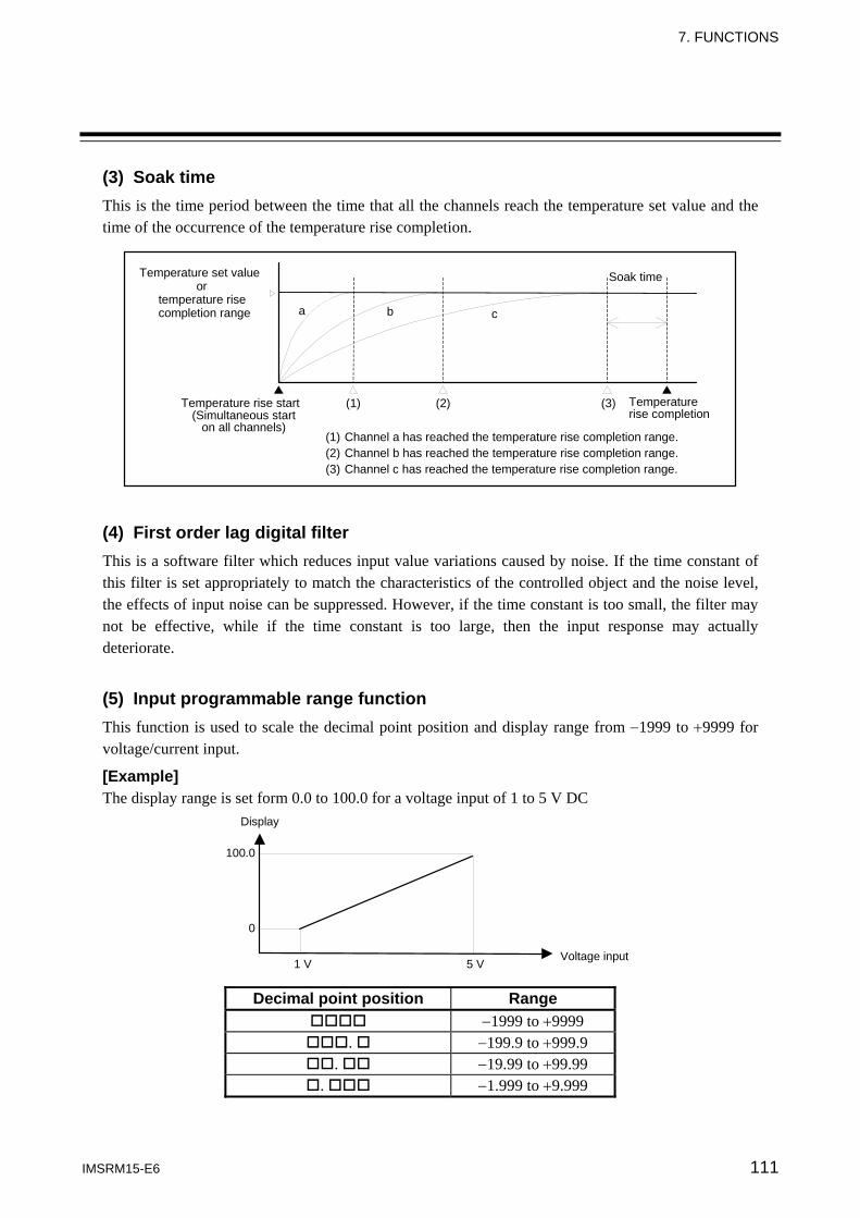
7. FUNCTIONS
IMSRM15-E6 111
(3) Soak time This is the time period between the time that all the channels reach the temperature set value and the time of the occurrence of the temperature rise completion.
Temperature set value
or temperature rise completion range
Soak time
Temperature rise start (Simultaneous start
on all channels)
Temperature rise completion
(1) (2) (3)
a b c
(1) Channel a has reached the temperature rise completion range. (2) Channel b has reached the temperature rise completion range. (3) Channel c has reached the temperature rise completion range.
(4) First order lag digital filter This is a software filter which reduces input value variations caused by noise. If the time constant of this filter is set appropriately to match the characteristics of the controlled object and the noise level, the effects of input noise can be suppressed. However, if the time constant is too small, the filter may not be effective, while if the time constant is too large, then the input response may actually deteriorate. (5) Input programmable range function This function is used to scale the decimal point position and display range from −1999 to +9999 for voltage/current input.
[Example] The display range is set form 0.0 to 100.0 for a voltage input of 1 to 5 V DC
Display
Voltage input
100.0
0
1 V 5 V Decimal point position Range
−1999 to +9999 . −199.9 to +999.9
. −19.99 to +99.99 . −1.999 to +9.999
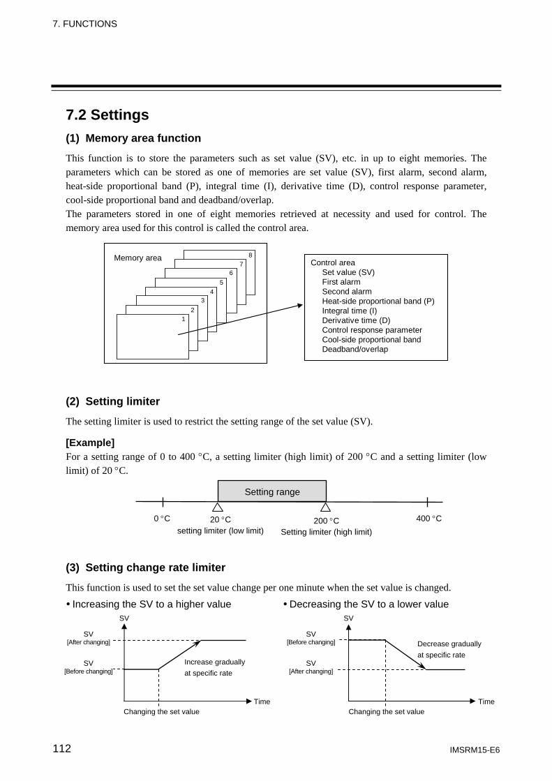
7. FUNCTIONS
IMSRM15-E6 112
7.2 Settings (1) Memory area function
This function is to store the parameters such as set value (SV), etc. in up to eight memories. The parameters which can be stored as one of memories are set value (SV), first alarm, second alarm, heat-side proportional band (P), integral time (I), derivative time (D), control response parameter, cool-side proportional band and deadband/overlap. The parameters stored in one of eight memories retrieved at necessity and used for control. The memory area used for this control is called the control area.
87
65
43
21
Memory area Control areaSet value (SV)First alarmSecond alarmHeat-side proportional band (P)Integral time (I)Derivative time (D)Control response parameterCool-side proportional bandDeadband/overlap
(2) Setting limiter
The setting limiter is used to restrict the setting range of the set value (SV). [Example] For a setting range of 0 to 400 °C, a setting limiter (high limit) of 200 °C and a setting limiter (low limit) of 20 °C. (3) Setting change rate limiter
This function is used to set the set value change per one minute when the set value is changed.
Increasing the SV to a higher value Decreasing the SV to a lower value
Setting range
0 °C 20 °C setting limiter (low limit)
400 °C 200 °C Setting limiter (high limit)
Increase gradually at specific rate
Changing the set value
SV [Before changing]
Time
SV
SV [After changing]
SV
Decrease gradually at specific rate
SV [After changing]
Time
SV [Before changing]
Changing the set value
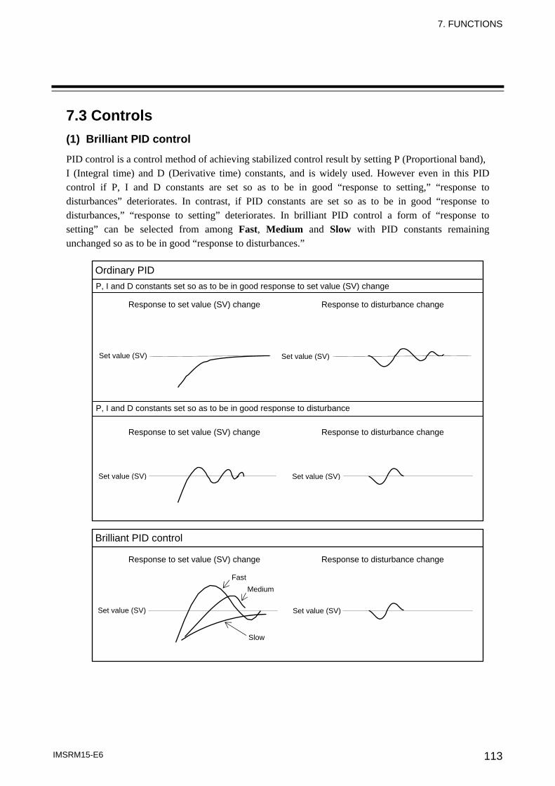
7. FUNCTIONS
IMSRM15-E6 113
7.3 Controls (1) Brilliant PID control
PID control is a control method of achieving stabilized control result by setting P (Proportional band), I (Integral time) and D (Derivative time) constants, and is widely used. However even in this PID control if P, I and D constants are set so as to be in good “response to setting,” “response to disturbances” deteriorates. In contrast, if PID constants are set so as to be in good “response to disturbances,” “response to setting” deteriorates. In brilliant PID control a form of “response to setting” can be selected from among Fast, Medium and Slow with PID constants remaining unchanged so as to be in good “response to disturbances.”
Ordinary PID P, I and D constants set so as to be in good response to set value (SV) change
Response to set value (SV) change Response to disturbance change
Set value (SV) Set value (SV)
Set value (SV) Set value (SV)
Set value (SV) Set value (SV)
P, I and D constants set so as to be in good response to disturbance
Brilliant PID control
FastMedium
Slow
Response to set value (SV) change Response to disturbance change
Response to set value (SV) change Response to disturbance change
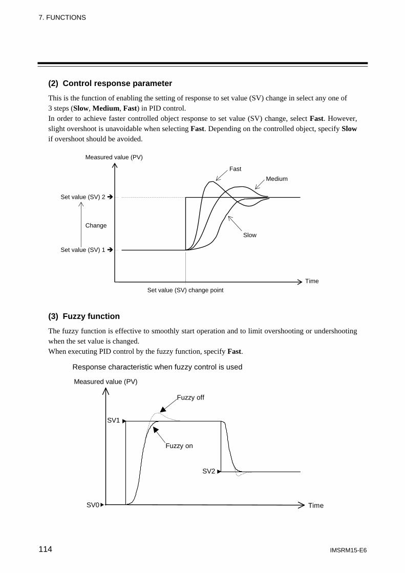
7. FUNCTIONS
IMSRM15-E6 114
(2) Control response parameter
This is the function of enabling the setting of response to set value (SV) change in select any one of 3 steps (Slow, Medium, Fast) in PID control. In order to achieve faster controlled object response to set value (SV) change, select Fast. However, slight overshoot is unavoidable when selecting Fast. Depending on the controlled object, specify Slow if overshoot should be avoided.
(3) Fuzzy function
The fuzzy function is effective to smoothly start operation and to limit overshooting or undershooting when the set value is changed. When executing PID control by the fuzzy function, specify Fast.
Response characteristic when fuzzy control is used
Measured value (PV)
SV1
SV2
SV0 Time
Fuzzy off
Fuzzy on
Time
Measured value (PV)
Set value (SV) 2
Set value (SV) 1
Change
Set value (SV) change point
Fast Medium
Slow
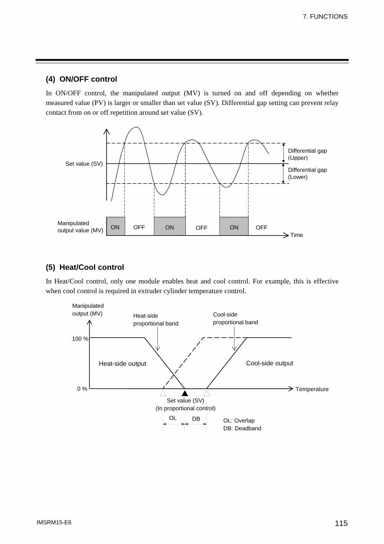
7. FUNCTIONS
IMSRM15-E6 115
(4) ON/OFF control
In ON/OFF control, the manipulated output (MV) is turned on and off depending on whether measured value (PV) is larger or smaller than set value (SV). Differential gap setting can prevent relay contact from on or off repetition around set value (SV). (5) Heat/Cool control
In Heat/Cool control, only one module enables heat and cool control. For example, this is effective when cool control is required in extruder cylinder temperature control.
Differential gap (Upper)
Set value (SV)
Manipulated output value (MV)
Time ON OFF
Differential gap (Lower)
ON ONOFF OFF
Manipulated output (MV)
100 %
0 %
Heat-side output
Heat-side proportional band
Cool-side proportional band
Set value (SV) (In proportional control)
OL DB OL: Overlap DB: Deadband
Temperature
Cool-side output
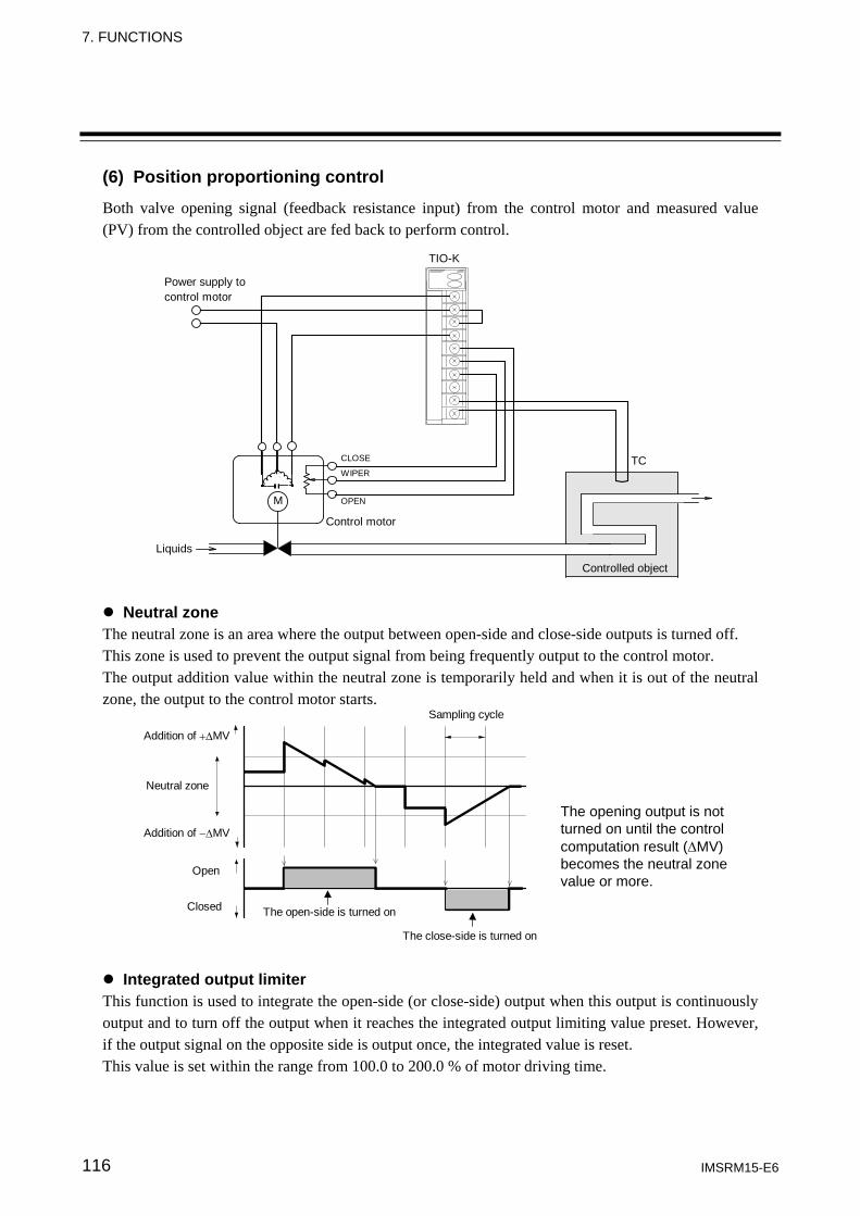
7. FUNCTIONS
IMSRM15-E6 116
(6) Position proportioning control
Both valve opening signal (feedback resistance input) from the control motor and measured value (PV) from the controlled object are fed back to perform control.
Power supply tocontrol motor
TIO-K
TC
Controlled object
Control motor
WIPER
CLOSE
OPENM
Liquids
Neutral zone The neutral zone is an area where the output between open-side and close-side outputs is turned off. This zone is used to prevent the output signal from being frequently output to the control motor. The output addition value within the neutral zone is temporarily held and when it is out of the neutral zone, the output to the control motor starts.
Addition of +ΔMV
Addition of −ΔMV
Neutral zone
Sampling cycle
Open
Closed
The close-side is turned on
The open-side is turned on
Integrated output limiter This function is used to integrate the open-side (or close-side) output when this output is continuously output and to turn off the output when it reaches the integrated output limiting value preset. However, if the output signal on the opposite side is output once, the integrated value is reset. This value is set within the range from 100.0 to 200.0 % of motor driving time.
The opening output is not turned on until the control computation result (ΔMV) becomes the neutral zone value or more.
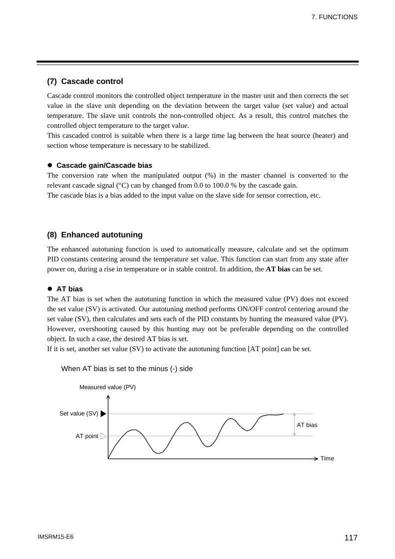
7. FUNCTIONS
IMSRM15-E6 117
(7) Cascade control
Cascade control monitors the controlled object temperature in the master unit and then corrects the set value in the slave unit depending on the deviation between the target value (set value) and actual temperature. The slave unit controls the non-controlled object. As a result, this control matches the controlled object temperature to the target value. This cascaded control is suitable when there is a large time lag between the heat source (heater) and section whose temperature is necessary to be stabilized.
Cascade gain/Cascade bias The conversion rate when the manipulated output (%) in the master channel is converted to the relevant cascade signal (°C) can by changed from 0.0 to 100.0 % by the cascade gain. The cascade bias is a bias added to the input value on the slave side for sensor correction, etc. (8) Enhanced autotuning
The enhanced autotuning function is used to automatically measure, calculate and set the optimum PID constants centering around the temperature set value. This function can start from any state after power on, during a rise in temperature or in stable control. In addition, the AT bias can be set.
AT bias The AT bias is set when the autotuning function in which the measured value (PV) does not exceed the set value (SV) is activated. Our autotuning method performs ON/OFF control centering around the set value (SV), then calculates and sets each of the PID constants by hunting the measured value (PV). However, overshooting caused by this hunting may not be preferable depending on the controlled object. In such a case, the desired AT bias is set. If it is set, another set value (SV) to activate the autotuning function [AT point] can be set.
When AT bias is set to the minus (-) side
Measured value (PV)
Set value (SV)
AT point
AT bias
Time
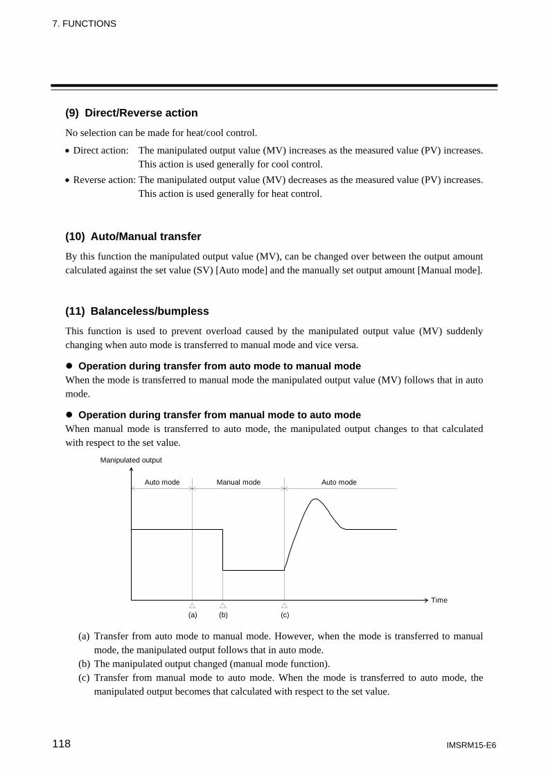
7. FUNCTIONS
IMSRM15-E6 118
(9) Direct/Reverse action
No selection can be made for heat/cool control.
• Direct action: The manipulated output value (MV) increases as the measured value (PV) increases. This action is used generally for cool control.
• Reverse action: The manipulated output value (MV) decreases as the measured value (PV) increases. This action is used generally for heat control.
(10) Auto/Manual transfer
By this function the manipulated output value (MV), can be changed over between the output amount calculated against the set value (SV) [Auto mode] and the manually set output amount [Manual mode]. (11) Balanceless/bumpless
This function is used to prevent overload caused by the manipulated output value (MV) suddenly changing when auto mode is transferred to manual mode and vice versa.
Operation during transfer from auto mode to manual mode When the mode is transferred to manual mode the manipulated output value (MV) follows that in auto mode.
Operation during transfer from manual mode to auto mode When manual mode is transferred to auto mode, the manipulated output changes to that calculated with respect to the set value.
Manipulated output
Auto mode Auto modeManual mode
Time
(a) (b) (c) (a) Transfer from auto mode to manual mode. However, when the mode is transferred to manual
mode, the manipulated output follows that in auto mode. (b) The manipulated output changed (manual mode function). (c) Transfer from manual mode to auto mode. When the mode is transferred to auto mode, the
manipulated output becomes that calculated with respect to the set value.
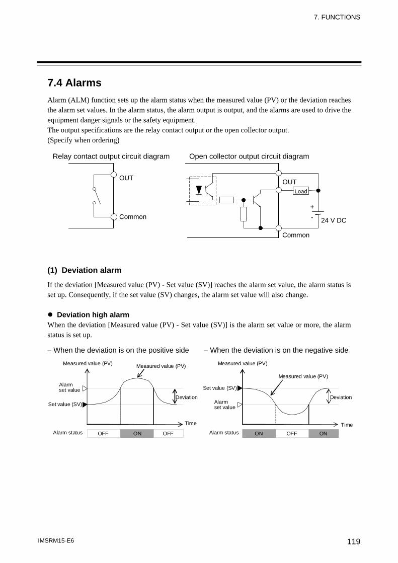
7. FUNCTIONS
IMSRM15-E6 119
7.4 Alarms Alarm (ALM) function sets up the alarm status when the measured value (PV) or the deviation reaches the alarm set values. In the alarm status, the alarm output is output, and the alarms are used to drive the equipment danger signals or the safety equipment. The output specifications are the relay contact output or the open collector output. (Specify when ordering) (1) Deviation alarm
If the deviation [Measured value (PV) - Set value (SV)] reaches the alarm set value, the alarm status is set up. Consequently, if the set value (SV) changes, the alarm set value will also change.
Deviation high alarm When the deviation [Measured value (PV) - Set value (SV)] is the alarm set value or more, the alarm status is set up. − When the deviation is on the positive side − When the deviation is on the negative side Measured value (PV)
Set value (SV)
Set value (SV) Alarm set value
Time
Deviation
TimeOFF OFFON OFF ON ON
Measured value (PV) Measured value (PV)
Measured value (PV)
Alarm set value
Alarm status Alarm status
Deviation
Relay contact output circuit diagram Open collector output circuit diagram
OUT
Common
OUT
Common
24 V DC
+ -
Load
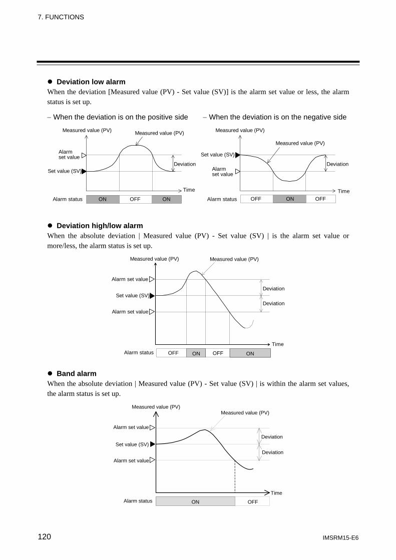
7. FUNCTIONS
IMSRM15-E6 120
Deviation low alarm When the deviation [Measured value (PV) - Set value (SV)] is the alarm set value or less, the alarm status is set up. − When the deviation is on the positive side − When the deviation is on the negative side
Measured value (PV)
Set value (SV)
Set value (SV)Alarmset value
Time
Deviation
TimeOFF OFFONOFFON ON
Measured value (PV) Measured value (PV)
Measured value (PV)
Alarmset value
Alarm status Alarm status
Deviation
Deviation high/low alarm When the absolute deviation | Measured value (PV) - Set value (SV) | is the alarm set value or more/less, the alarm status is set up.
Set value (SV)
Time
OFF OFFON ON
Measured value (PV) Measured value (PV)
Alarm set value
Alarm set value
Deviation
Deviation
Alarm status
Band alarm When the absolute deviation | Measured value (PV) - Set value (SV) | is within the alarm set values, the alarm status is set up.
Time
ON OFF
Measured value (PV)Measured value (PV)
Set value (SV)
Alarm set value
Alarm set value
Deviation
Deviation
Alarm status
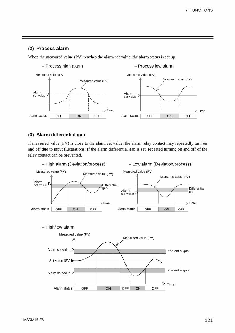
7. FUNCTIONS
IMSRM15-E6 121
(2) Process alarm
When the measured value (PV) reaches the alarm set value, the alarm status is set up.
− Process high alarm − Process low alarm
Time TimeOFF OFFON ON OFF OFF
Measured value (PV) Measured value (PV)
Measured value (PV) Measured value (PV)
Alarm set value
Alarm set value
Alarm status Alarm status (3) Alarm differential gap
If measured value (PV) is close to the alarm set value, the alarm relay contact may repeatedly turn on and off due to input fluctuations. If the alarm differential gap is set, repeated turning on and off of the relay contact can be prevented.
− High alarm (Deviation/process) − Low alarm (Deviation/process)
TimeTime
Differentialgap
OFF ON OFF OFF ON OFF
Measured value (PV) Measured value (PV)Measured value (PV)
Measured value (PV)Alarmset value
Alarmset value
Alarm status Alarm status
Differentialgap
− High/low alarm
Alarm status
Differential gap
Time OFF ON OFF ON OFF
Set value (SV)
Measured value (PV) Measured value (PV)
Alarm set value
Alarm set valueDifferential gap
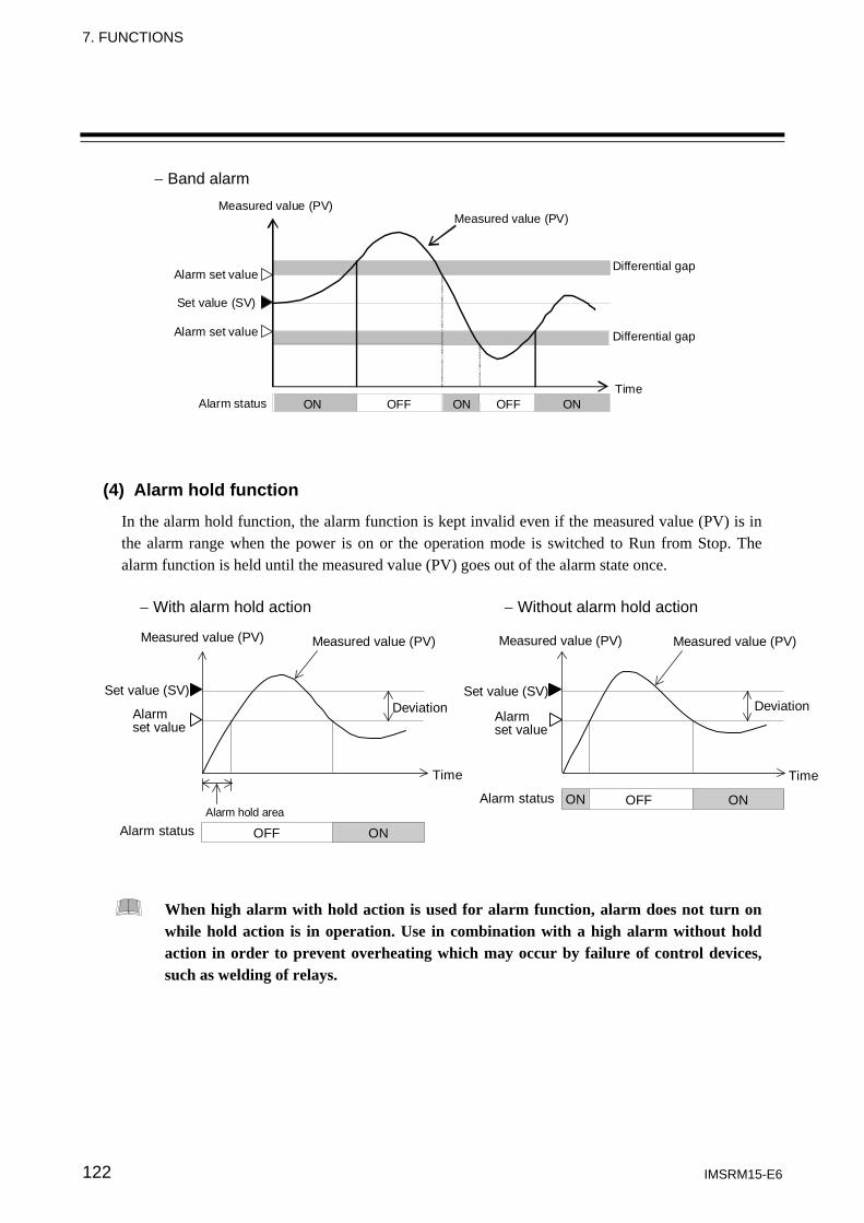
7. FUNCTIONS
IMSRM15-E6 122
− Band alarm
Time ON OFF ON OFF ON
Measured value (PV) Measured value (PV)
Alarm set value
Alarm set value
Set value (SV)
Alarm status
Differential gap
Differential gap
(4) Alarm hold function
In the alarm hold function, the alarm function is kept invalid even if the measured value (PV) is in the alarm range when the power is on or the operation mode is switched to Run from Stop. The alarm function is held until the measured value (PV) goes out of the alarm state once.
− With alarm hold action − Without alarm hold action
Time Time
Alarm hold area
OFF ON
OFF ONON
Measured value (PV) Measured value (PV) Measured value (PV) Measured value (PV)
Alarmset value
Alarmset value
Set value (SV) Set value (SV)
Alarm status
Alarm status
Deviation Deviation
When high alarm with hold action is used for alarm function, alarm does not turn on while hold action is in operation. Use in combination with a high alarm without hold action in order to prevent overheating which may occur by failure of control devices, such as welding of relays.
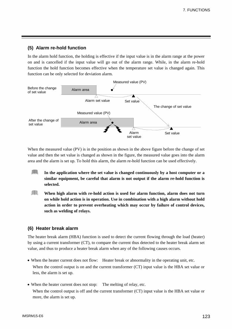
7. FUNCTIONS
IMSRM15-E6 123
(5) Alarm re-hold function
In the alarm hold function, the holding is effective if the input value is in the alarm range at the power on and is cancelled if the input value will go out of the alarm range. While, in the alarm re-hold function the hold function becomes effective when the temperature set value is changed again. This function can be only selected for deviation alarm.
Set value
Alarmset value
Measured value (PV)
Alarm area
Before the changeof set value
Measured value (PV)
Alarm set value
The change of set value
Alarm area
Set value
After the change ofset value
When the measured value (PV) is in the position as shown in the above figure before the change of set value and then the set value is changed as shown in the figure, the measured value goes into the alarm area and the alarm is set up. To hold this alarm, the alarm re-hold function can be used effectively.
In the application where the set value is changed continuously by a host computer or a similar equipment, be careful that alarm is not output if the alarm re-hold function is selected.
When high alarm with re-hold action is used for alarm function, alarm does not turn on while hold action is in operation. Use in combination with a high alarm without hold action in order to prevent overheating which may occur by failure of control devices, such as welding of relays.
(6) Heater break alarm
The heater break alarm (HBA) function is used to detect the current flowing through the load (heater) by using a current transformer (CT), to compare the current thus detected to the heater break alarm set value, and thus to produce a heater break alarm when any of the following causes occurs. • When the heater current does not flow: Heater break or abnormality in the operating unit, etc.
When the control output is on and the current transformer (CT) input value is the HBA set value or less, the alarm is set up.
• When the heater current does not stop: The melting of relay, etc.
When the control output is off and the current transformer (CT) input value is the HBA set value or more, the alarm is set up.
7. FUNCTIONS
IMSRM15-E6 124
(7) Loop break alarm
The loop break alarm (LBA) function is used to detect a load (heater) break or a failure in the external actuator (magnet relay, etc.), or a failure in the control loop caused by an input (sensor) break. This function monitors the measured value (PV) variation at LBA setting time intervals from the time the output exceeds 100 % (or output limiter: high limit) or falls below 0 % (or output limiter: low limit), then detects a heater or input break. ■Alarm action The LBA function produces the alarm when any of the following causes occurs.
Heat control (LBA triggering width: 2 °C [°F] fixed) When the output falls below 0 % (or output limiter: low limit)
For direct action: This alarm is produced when the measured value (PV) does not rise beyond the LBA triggering width within the LBA setting time.
For reverse action: This alarm is produced when the measured value (PV) does not fall below the LBA triggering width within the LBA setting time.
When the output exceeds 100 % (or output limiter: high limit) For direct action: This alarm is produced when the measured value (PV) does not fall below the
LBA triggering width within the LBA setting time. For reverse action: This alarm is produced when the measured value (PV) does not rise beyond the
LBA triggering width within the LBA setting time. Heat/Cool control (LBA triggering width: 2 °C [°F] fixed)
When the heat-side output exceeds 100 % (or output limiter: high limit) and the cool-side output falls below 0 % This alarm is produced when the measured value (PV) does not rise beyond the LBA triggering width within the LBA setting time.
When the heat-side output falls below 0 % and the cool-side output exceeds 100 % (or output limiter: low-limit) This alarm is produced when the measured value (PV) does not rise beyond the LBA triggering width within the LBA setting time.
Position proportioning control (LBA triggering width: 2 °C [°F] fixed)
When the opening exceeds 100 % (or output limiter: high limit) This alarm is produced when the measured value (PV) does not rise beyond the LBA triggering width within the LBA setting time.
When the opening less than 0 % (or output limiter: low limit) This alarm is produced when the measured value (PV) does not rise beyond the LBA triggering width within the LBA setting time.
If the autotuning function is used, the LBA setting time twice as large as the integral time is automatically set. The LBA setting time does not change even if the integral time is changed. In position proportioning control, the output limiter setting functions as the LBA high/low limit. (The output limited does not function as a control limited.)
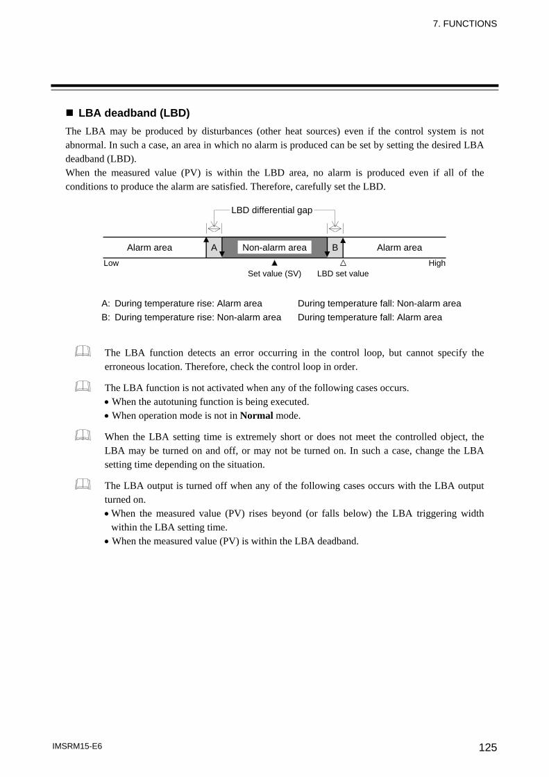
7. FUNCTIONS
IMSRM15-E6 125
LBA deadband (LBD) The LBA may be produced by disturbances (other heat sources) even if the control system is not abnormal. In such a case, an area in which no alarm is produced can be set by setting the desired LBA deadband (LBD). When the measured value (PV) is within the LBD area, no alarm is produced even if all of the conditions to produce the alarm are satisfied. Therefore, carefully set the LBD.
The LBA function detects an error occurring in the control loop, but cannot specify the erroneous location. Therefore, check the control loop in order.
The LBA function is not activated when any of the following cases occurs. • When the autotuning function is being executed. • When operation mode is not in Normal mode.
When the LBA setting time is extremely short or does not meet the controlled object, the LBA may be turned on and off, or may not be turned on. In such a case, change the LBA setting time depending on the situation.
The LBA output is turned off when any of the following cases occurs with the LBA output turned on. • When the measured value (PV) rises beyond (or falls below) the LBA triggering width
within the LBA setting time. • When the measured value (PV) is within the LBA deadband.
A: During temperature rise: Alarm area During temperature fall: Non-alarm area B: During temperature rise: Non-alarm area During temperature fall: Alarm area
LBD differential gap
Alarm area Non-alarm area
Set value (SV) LBD set valueLow High
A B Alarm area
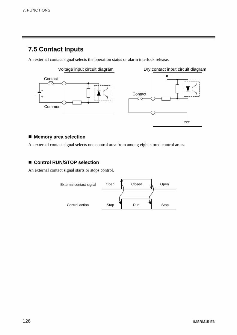
7. FUNCTIONS
IMSRM15-E6 126
7.5 Contact Inputs An external contact signal selects the operation status or alarm interlock release.
Memory area selection An external contact signal selects one control area from among eight stored control areas.
Control RUN/STOP selection An external contact signal starts or stops control.
Open Closed Open
Stop Run Stop Control action
External contact signal
Voltage input circuit diagram Dry contact input circuit diagram
Contact
Contact
Common
- +
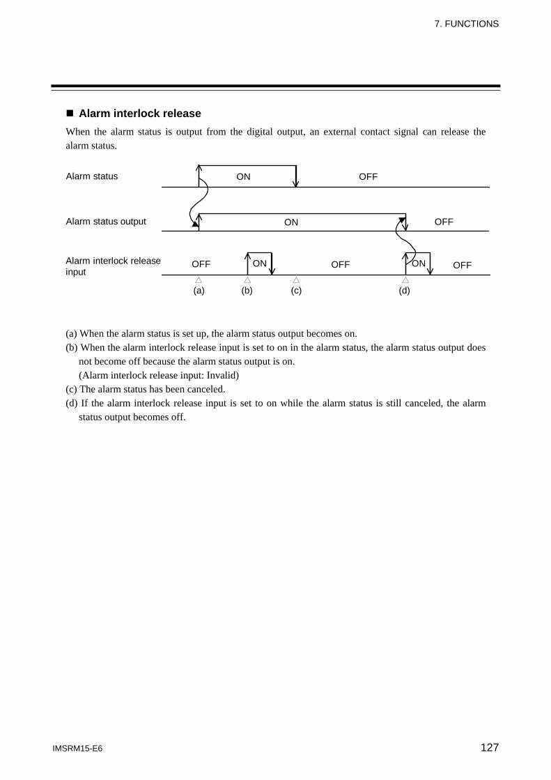
7. FUNCTIONS
IMSRM15-E6 127
Alarm interlock release When the alarm status is output from the digital output, an external contact signal can release the alarm status.
Alarm interlock releaseinput
Alarm status output
Alarm status
(a) (b) (c) (d)
ON OFF
ON
ON
OFF
OFFOFF OFFON
(a) When the alarm status is set up, the alarm status output becomes on. (b) When the alarm interlock release input is set to on in the alarm status, the alarm status output does
not become off because the alarm status output is on. (Alarm interlock release input: Invalid)
(c) The alarm status has been canceled. (d) If the alarm interlock release input is set to on while the alarm status is still canceled, the alarm
status output becomes off.
128 IMSRM15-E6
8. SPECIFICATIONS
8.1 H-PCP Module Basic functions
Data supervision: Operating and system data Control unit diagnosis: Function modules configuration check Self-diagnostic: Check item: ROM/RAM check, Watchdog timer and
CPU power supply monitoring If error occurs in self-diagnosis, the hardware will automatically return the module outputs to the OFF position.
Memory backup: Module with non-volatile memory *: Backed up by non-volatile memory (FeRAM) Number of writing: Approximately ten billion times Depending on storage and operating conditions. Data storage period: Approximately 10 years
Module with lithium battery *: Lithium battery for RAM backup, approximate 10 years life for data retention.
* To distinguish your module between the above two types, please contact RKC office or the agent.
Power input Power supply voltage: 90 to 132 V AC (50/60 Hz) [Including power supply voltage variation] (Rating: 100 to 120 V AC) 180 to 264 V AC (50/60 Hz) [Including power supply voltage variation] (Rating: 200 to 240 V AC) 21.6 to 26.4 V DC [Including power supply voltage variation] (Rating: 24 V DC) Specify when ordering Power consumption: H-PCP-A: 100 to 120 V AC: 20 VA max. 24 V DC: 30 W max. 200 to 240 V AC: 20 VA max. H-PCP-B: 100 to 120 V AC: 25 VA max. 24 V DC: 30 W max. 200 to 240 V AC: 25 VA max.
CE/UL/cUL (or CSA) approved instrument: 100 to 120 V AC: 40 VA max. 24 V DC: 21 W max. 200 to 240 V AC: 50 VA max.
Surge current: 30 A or less
Power output (For function modules) Output voltage/current: H-PCP-A: 5 V DC: 1.6 A max. 12 V DC: 0.4 A max. H-PCP-B: 5 V DC: 1.6 A max. 12 V DC: 1.0 A max. CE/UL/cUL (or CSA) approved instrument: 5 V DC, 1.7 A max. 12 V DC, 1.0 A max. Must be used within the maximum power consumption value. Overcurrent protection: Fold-back limiting method: 5 V
8. SPECIFICATIONS
IMSRM15-E6 129
Digital output Failure output: Relay contact output Number of outputs: 1 point Rating: 250 V AC, 0.1 A (Resistive load) [CE/UL/cUL (or CSA) approved instrument: 30 V DC, 0.1 A] Electrical life: 300,000 times or more (Rated load) Contact type: 1a contact Failure action: Open at error occurrence Digital output: 1-2 Relay contact output Number of outputs: 4 points (H-PCP-B type: 2 points) Rating: 250 V AC, 0.1 A (Resistive load) [CE/UL/ cUL (or CSA) approved instrument: 30 V DC, 0.1 A] Electrical life: 300,000 times or more (Rated load) Contact type: 1a contact
Open collector output Number of outputs: 4 points (H-PCP-B type: 2 points) Load voltage: 12 to 24 V DC Maximum load current: 0.1 A/point, 0.8 A/common
1 Specify either relay contact output or open collector output when ordering. 2 Digital output can be selected from the following:
- Temperature alarm (alarm 1, alarm 2) - AI alarm (alarm 1, alarm 2) - Heater break alarm (HBA) - Burnout alarm - Loop break alarm (LBA) - Temperature rise completion
Digital input (Only for H-PCP-B type) Number of inputs: 3 points Input type: Source type Rated input voltage: 24 V DC Input voltage range: 21.6 to 26.4 V DC Rated input current: 6.7 mA/point (24 V DC) Input impedance: 3.6 kΩ Input operating voltage: ON voltage: 18.5 V DC OFF voltage: 9.0 V DC Allocated functions: 1. Memory area transfer (8 memory areas) 2. Control RUN/STOP and memory area transfer (4 memory areas) 3. Alarm interlock release, control RUN/STOP and memory area transfer (2 memory areas) Selectable
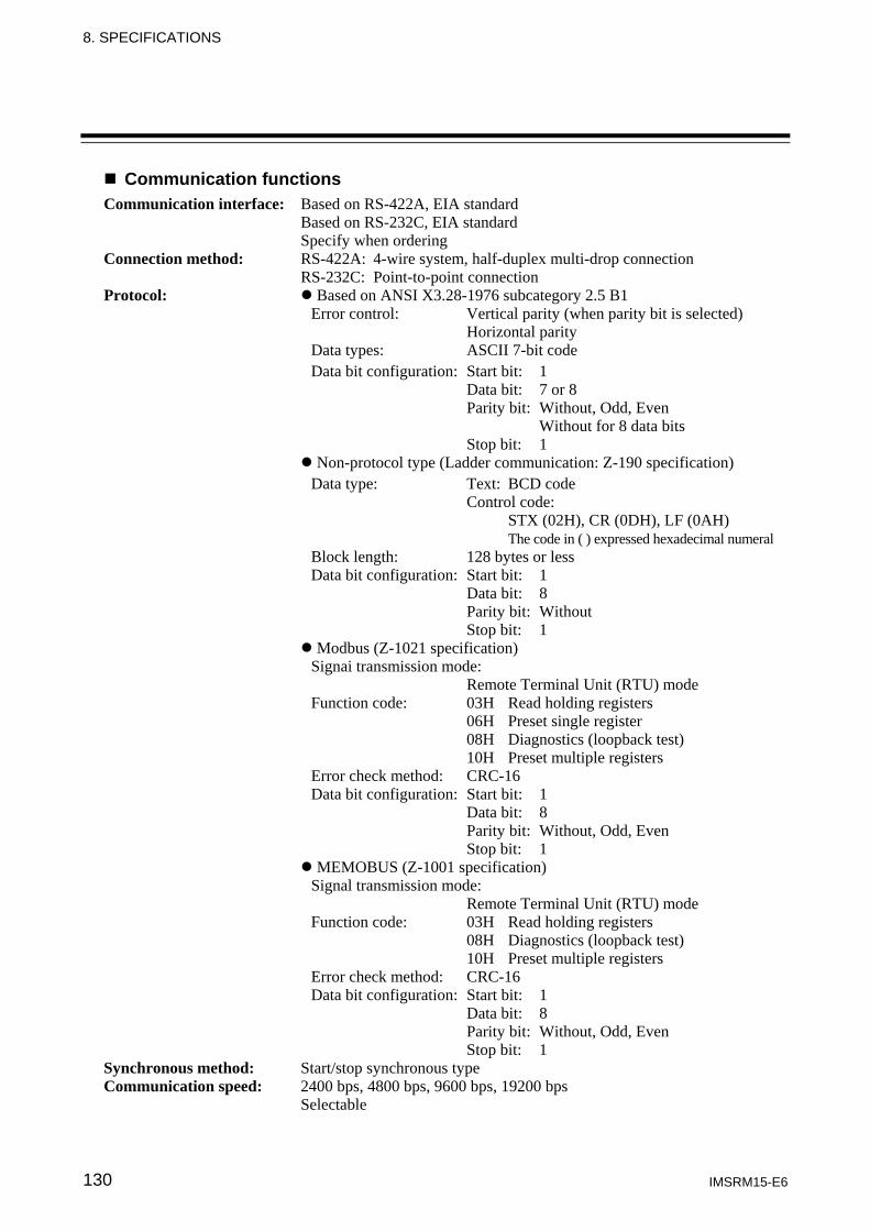
8. SPECIFICATIONS
IMSRM15-E6 130
Communication functions Communication interface: Based on RS-422A, EIA standard
Based on RS-232C, EIA standard Specify when ordering
Connection method: RS-422A: 4-wire system, half-duplex multi-drop connection RS-232C: Point-to-point connection
Protocol: Based on ANSI X3.28-1976 subcategory 2.5 B1 Error control: Vertical parity (when parity bit is selected) Horizontal parity Data types: ASCII 7-bit code Data bit configuration: Start bit: 1 Data bit: 7 or 8 Parity bit: Without, Odd, Even Without for 8 data bits Stop bit: 1 Non-protocol type (Ladder communication: Z-190 specification) Data type: Text: BCD code Control code: STX (02H), CR (0DH), LF (0AH) The code in ( ) expressed hexadecimal numeral Block length: 128 bytes or less Data bit configuration: Start bit: 1 Data bit: 8 Parity bit: Without Stop bit: 1
Modbus (Z-1021 specification) Signai transmission mode: Remote Terminal Unit (RTU) mode Function code: 03H Read holding registers 06H Preset single register 08H Diagnostics (loopback test) 10H Preset multiple registers Error check method: CRC-16 Data bit configuration: Start bit: 1 Data bit: 8 Parity bit: Without, Odd, Even Stop bit: 1
MEMOBUS (Z-1001 specification) Signal transmission mode: Remote Terminal Unit (RTU) mode Function code: 03H Read holding registers 08H Diagnostics (loopback test) 10H Preset multiple registers Error check method: CRC-16 Data bit configuration: Start bit: 1 Data bit: 8 Parity bit: Without, Odd, Even Stop bit: 1 Synchronous method: Start/stop synchronous type Communication speed: 2400 bps, 4800 bps, 9600 bps, 19200 bps Selectable
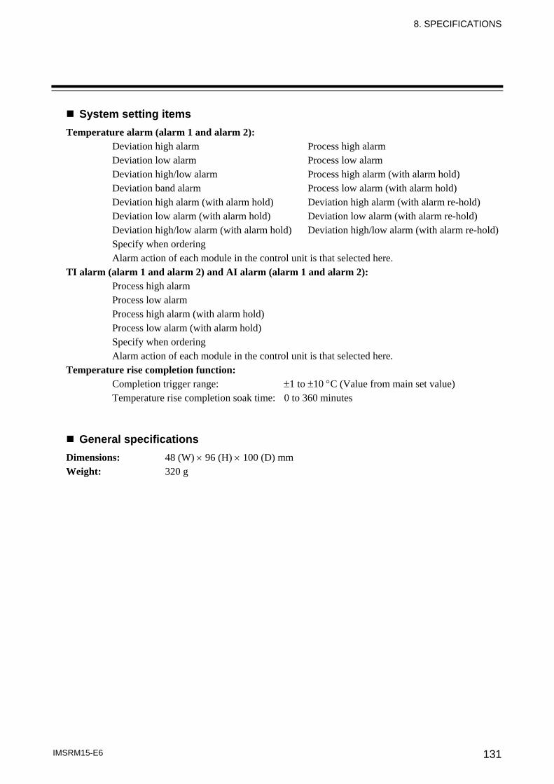
8. SPECIFICATIONS
IMSRM15-E6 131
System setting items Temperature alarm (alarm 1 and alarm 2):
Deviation high alarm Process high alarm Deviation low alarm Process low alarm Deviation high/low alarm Process high alarm (with alarm hold) Deviation band alarm Process low alarm (with alarm hold) Deviation high alarm (with alarm hold) Deviation high alarm (with alarm re-hold) Deviation low alarm (with alarm hold) Deviation low alarm (with alarm re-hold) Deviation high/low alarm (with alarm hold) Deviation high/low alarm (with alarm re-hold) Specify when ordering Alarm action of each module in the control unit is that selected here.
TI alarm (alarm 1 and alarm 2) and AI alarm (alarm 1 and alarm 2): Process high alarm Process low alarm Process high alarm (with alarm hold) Process low alarm (with alarm hold) Specify when ordering Alarm action of each module in the control unit is that selected here.
Temperature rise completion function: Completion trigger range: ±1 to ±10 °C (Value from main set value) Temperature rise completion soak time: 0 to 360 minutes
General specifications Dimensions: 48 (W) × 96 (H) × 100 (D) mm Weight: 320 g
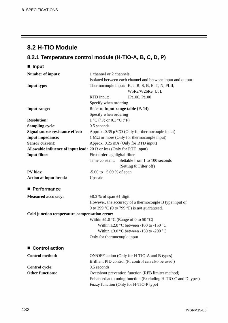
8. SPECIFICATIONS
IMSRM15-E6 132
8.2 H-TIO Module 8.2.1 Temperature control module (H-TIO-A, B, C, D, P)
Input Number of inputs: 1 channel or 2 channels Isolated between each channel and between input and output Input type: Thermocouple input: K, J, R, S, B, E, T, N, PLII, W5Re/W26Re, U, L RTD input: JPt100, Pt100 Specify when ordering Input range: Refer to Input range table (P. 14) Specify when ordering Resolution: 1 °C (°F) or 0.1 °C (°F) Sampling cycle: 0.5 seconds Signal source resistance effect: Approx. 0.35 μV/Ω (Only for thermocouple input) Input impedance: 1 MΩ or more (Only for thermocouple input) Sensor current: Approx. 0.25 mA (Only for RTD input) Allowable influence of input lead: 20 Ω or less (Only for RTD input) Input filter: First order lag digital filter Time constant: Settable from 1 to 100 seconds (Setting 0: Filter off) PV bias: -5.00 to +5.00 % of span Action at input break: Upscale
Performance Measured accuracy: ±0.3 % of span ±1 digit
However, the accuracy of a thermocouple B type input of 0 to 399 °C (0 to 799 °F) is not guaranteed.
Cold junction temperature compensation error: Within ±1.0 °C (Range of 0 to 50 °C) Within ±2.0 °C between -100 to -150 °C Within ±3.0 °C between -150 to -200 °C Only for thermocouple input
Control action Control method: ON/OFF action (Only for H-TIO-A and B types) Brilliant PID control (PI control can also be used.) Control cycle: 0.5 seconds Other functions: Overshoot prevention function (RFB limiter method) Enhanced autotuning function (Excluding H-TIO-C and D types) Fuzzy function (Only for H-TIO-P type)
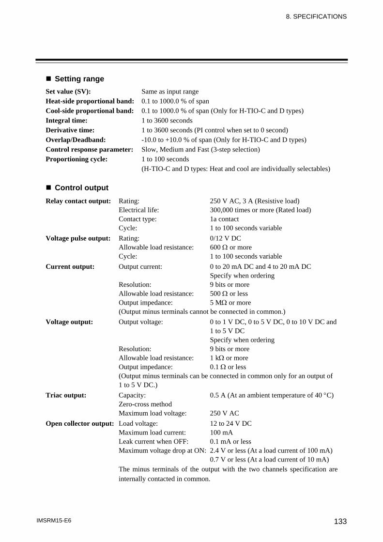
8. SPECIFICATIONS
IMSRM15-E6 133
Setting range Set value (SV): Same as input range Heat-side proportional band: 0.1 to 1000.0 % of span Cool-side proportional band: 0.1 to 1000.0 % of span (Only for H-TIO-C and D types) Integral time: 1 to 3600 seconds Derivative time: 1 to 3600 seconds (PI control when set to 0 second) Overlap/Deadband: -10.0 to +10.0 % of span (Only for H-TIO-C and D types) Control response parameter: Slow, Medium and Fast (3-step selection) Proportioning cycle: 1 to 100 seconds (H-TIO-C and D types: Heat and cool are individually selectables)
Control output Relay contact output: Rating: 250 V AC, 3 A (Resistive load) Electrical life: 300,000 times or more (Rated load) Contact type: 1a contact Cycle: 1 to 100 seconds variable Voltage pulse output: Rating: 0/12 V DC Allowable load resistance: 600 Ω or more Cycle: 1 to 100 seconds variable Current output: Output current: 0 to 20 mA DC and 4 to 20 mA DC Specify when ordering Resolution: 9 bits or more Allowable load resistance: 500 Ω or less Output impedance: 5 MΩ or more (Output minus terminals cannot be connected in common.) Voltage output: Output voltage: 0 to 1 V DC, 0 to 5 V DC, 0 to 10 V DC and 1 to 5 V DC Specify when ordering Resolution: 9 bits or more Allowable load resistance: 1 kΩ or more Output impedance: 0.1 Ω or less (Output minus terminals can be connected in common only for an output of 1 to 5 V DC.) Triac output: Capacity: 0.5 A (At an ambient temperature of 40 °C) Zero-cross method Maximum load voltage: 250 V AC Open collector output: Load voltage: 12 to 24 V DC Maximum load current: 100 mA Leak current when OFF: 0.1 mA or less Maximum voltage drop at ON: 2.4 V or less (At a load current of 100 mA) 0.7 V or less (At a load current of 10 mA) The minus terminals of the output with the two channels specification are internally contacted in common.
8. SPECIFICATIONS
IMSRM15-E6 134
Temperature alarm function Number of alarms: 2 points
Alarm types: Deviation high alarm Process high alarm Deviation low alarm Process low alarm Deviation high/low alarm Process high alarm (with alarm hold) Deviation band alarm Process low alarm (with alarm hold) Deviation high alarm (with alarm hold) Deviation high alarm (with alarm re-hold) Deviation low alarm (with alarm hold) Deviation low alarm (with alarm re-hold) Deviation high/low alarm (with alarm hold) Deviation high/low alarm (with alarm re-hold) Specify when ordering (Alarm action is specified for the H-PCP module.)
Setting range: -span to +span: Deviation high alarm, Deviation low alarm, Deviation high alarm (with alarm hold), Deviation low alarm (with alarm hold) 0 to span: Deviation high/low alarm, Deviation band alarm, Deviation high/low alarm (with alarm hold) Same as input range: Process high alarm, Process low alarm, Process high alarm (with alarm hold), Process low alarm (with alarm hold) Specify when ordering (Alarm action is specified for the H-PCP module.)
Setting resolution: Same as input resolution Alarm output: This module outputs alarm status to the H-PCP module as data.
Alarm output (Only for H-TIO-A type) [Optional] Number of outputs: 1 point Select any of temperature alarm output 1 (ALM1), temperature alarm output 2 (ALM2), heater break alarm output (HBA) or loop break alarm output (LBA). Relay contact output: Rating: 250 V AC 24 V DC 2 A (Resistive load) Electrical life: 300,000 times or more (Rated load) Contact type: 1a contact Minimum switching voltage and current: 5 V DC 1 mA Isolation method: Photocoupler isolation
8. SPECIFICATIONS
IMSRM15-E6 135
Heater break alarm function (Only for H-TIO-A, C and D type) [Optional] Number of inputs: 1 point/control loop Setting range: 0.0 to 100.0 A Accuracy of heater current measurement: 5 % of input value or ±2 A (The value whichever is greater) Input current: 0 to 30 A: CTL-6-P-N 0 to 100 A: CTL-12-S56-10L-N Current transformer: CTL-6-P-N, CTL-12-S56-10L-N Specify when ordering Input rating: Maximum current: 130 mA Input impedance: 10 Ω Alarm output: This module outputs alarm status to the H-PCP module as data.
Loop break alarm function Setting range: LBA setting time: 1 to 7200 seconds LBA deadband (LBD): Same as input range (LBD is automatically as the value of two times of integral value after the completion of autotuning.) Alarm output: This module outputs alarm status to the H-PCP module as data.
Self-diagnostic Check item: RAM check Adjustment data check Input value check Watchdog timer Operation at error occurrence in self-diagnosis: FAIL lamp lights All channel control outputs are turned off. Reset state
Manual setting function Auto/Manual transfer: Either Auto or Manual control can be selected. Setting range: -5.0 to +105.0 % Balanceless bumpless: Balanceless bumpless transfer between Auto and Manual (both directions).
General specifications Dimensions: H-TIO-A, B, C, P: 24 (W) × 96 (H) × 100 (D) mm H-TIO-D: 48 (W) × 96 (H) × 100 (D) mm Weight: H-TIO-A, B, C, P: 120 g H-TIO-D: 240 g
8. SPECIFICATIONS
IMSRM15-E6 136
8.2.2 High accuracy temperature control module (H-TIO-E, F, G, R) Input
Number of inputs: 1 channel or 2 channels Isolated between input and output (For H-TIO-F type, not isolated between each channel) Input type: Thermocouple input: K, J, R, S, B, E, T, N, PLII, W5Re/W26Re, U, L RTD input: JPt100, Pt100 Specify when ordering Input range: Refer to Input range table (P. 14) Specify when ordering Resolution: 1 °C (°F) or 0.1 °C (°F) 0.01 °C (Only for H-TIO-E type RTD input) Sampling cycle: H-TIO-E, G, R: 0.1 seconds H-TIO-F: 0.2 seconds Signal source resistance effect: Approx. 0.3 μV/Ω (Only for thermocouple input) Input impedance: 1 MΩ or more (Only for thermocouple input) Sensor current: Approx. 0.3 mA (Only for RTD input) Allowable influence of input lead: 10 Ω or less (Only for RTD input) Input filter: First order lag digital filter Time constant: Settable from 0.1 to 100.0 seconds (Setting 0.0: Filter off) PV bias: -5.00 to +5.00 % of span Action at input break: Upscale or downscale can be selected
Performance Measured accuracy: H-TIO-E, G, R: ±0.1 % of span ±1 digit
H-TIO-F: ±0.2 % of span ±1 digit However, the accuracy of a thermocouple B type input of 0 to 399 °C (0 to 799 °F) is not guaranteed.
Cold junction temperature compensation error: Within ±0.5 °C (Range of 0 to 50 °C) Within ±2.0 °C between -100 to -150 °C Within ±3.0 °C between -150 to -200 °C Only for thermocouple input
Control action Control method: ON/OFF action (Only for H-TIO-E, F and R types) Brilliant PID control (PI control can also be used.) Control cycle: H-TIO-E, G, R: 0.1 seconds H-TIO-F: 0.2 seconds Other functions: Overshoot prevention function (RFB limiter method) Enhanced autotuning function (Excluding H-TIO-G type) Fuzzy function (Only for H-TIO-R type)
8. SPECIFICATIONS
IMSRM15-E6 137
Setting range Set value (SV): Same as input range Heat-side proportional band: 0.1 to 1000.0 % of span Cool-side proportional band: 0.1 to 1000.0 % of span (Only for H-TIO-G type) Integral time: 1 to 3600 seconds Derivative time: 1 to 3600 seconds (PI control when set to 0 second) Overlap/Deadband: -10.0 to +10.0 % of span (Only for H-TIO-G type) Control response parameter: Slow, Medium and Fast (3-step selection) Proportioning cycle: 1 to 100 seconds (H-TIO-G type: Heat and cool are individually selectables)
Control output Relay contact output: Rating: 250 V AC, 3 A (Resistive load) Electrical life: 300,000 times or more (Rated load) Contact type: 1a contact Cycle: 1 to 100 seconds variable Voltage pulse output: Rating: 0/12 V DC Allowable load resistance: 600 Ω or more Cycle: 1 to 100 seconds variable Current output: Output current: 0 to 20 mA DC and 4 to 20 mA DC Specify when ordering Resolution: 11 bits or more Allowable load resistance: 500 Ω or less Output impedance: 5 MΩ or more (Output minus terminals cannot be connected in common.) Voltage output: Output voltage: 0 to 1 V DC, 0 to 5 V DC, 0 to 10 V DC and 1 to 5 V DC Specify when ordering Resolution: 11 bits or more Allowable load resistance: 1 kΩ or more Output impedance: 0.1 Ω or less (Output minus terminals can be connected in common only for an output of 1 to 5 V DC.) Triac output: Capacity: 0.5 A (At an ambient temperature of 40 °C) Zero-cross method Maximum load voltage: 250 V AC Open collector output: Load voltage: 12 to 24 V DC Maximum load current: 100 mA Leak current when OFF: 0.1 mA or less Maximum voltage drop at ON: 2.4 V or less (At a load current of 100 mA) 0.7 V or less (At a load current of 10 mA)
The minus terminals of the output with the two channels specification are internally contacted in common.
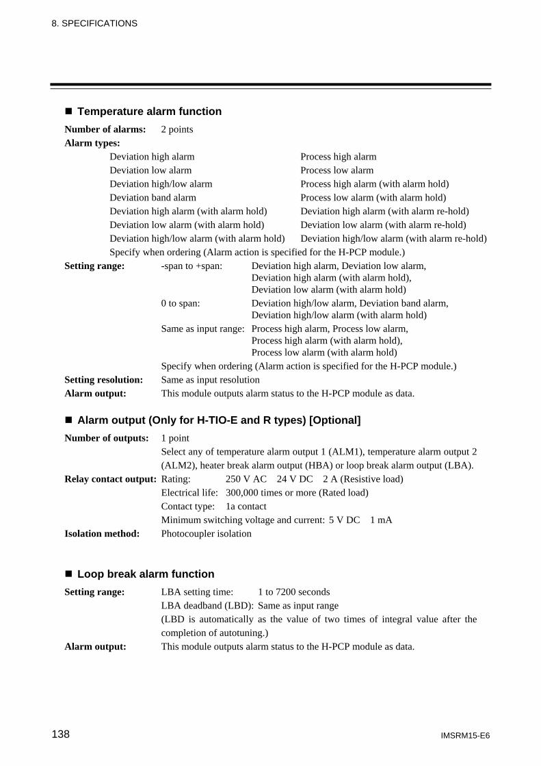
8. SPECIFICATIONS
IMSRM15-E6 138
Temperature alarm function Number of alarms: 2 points
Alarm types: Deviation high alarm Process high alarm Deviation low alarm Process low alarm Deviation high/low alarm Process high alarm (with alarm hold) Deviation band alarm Process low alarm (with alarm hold) Deviation high alarm (with alarm hold) Deviation high alarm (with alarm re-hold) Deviation low alarm (with alarm hold) Deviation low alarm (with alarm re-hold) Deviation high/low alarm (with alarm hold) Deviation high/low alarm (with alarm re-hold) Specify when ordering (Alarm action is specified for the H-PCP module.)
Setting range: -span to +span: Deviation high alarm, Deviation low alarm, Deviation high alarm (with alarm hold), Deviation low alarm (with alarm hold) 0 to span: Deviation high/low alarm, Deviation band alarm, Deviation high/low alarm (with alarm hold) Same as input range: Process high alarm, Process low alarm, Process high alarm (with alarm hold), Process low alarm (with alarm hold) Specify when ordering (Alarm action is specified for the H-PCP module.)
Setting resolution: Same as input resolution Alarm output: This module outputs alarm status to the H-PCP module as data.
Alarm output (Only for H-TIO-E and R types) [Optional] Number of outputs: 1 point Select any of temperature alarm output 1 (ALM1), temperature alarm output 2 (ALM2), heater break alarm output (HBA) or loop break alarm output (LBA). Relay contact output: Rating: 250 V AC 24 V DC 2 A (Resistive load) Electrical life: 300,000 times or more (Rated load) Contact type: 1a contact Minimum switching voltage and current: 5 V DC 1 mA Isolation method: Photocoupler isolation
Loop break alarm function Setting range: LBA setting time: 1 to 7200 seconds LBA deadband (LBD): Same as input range (LBD is automatically as the value of two times of integral value after the completion of autotuning.) Alarm output: This module outputs alarm status to the H-PCP module as data.
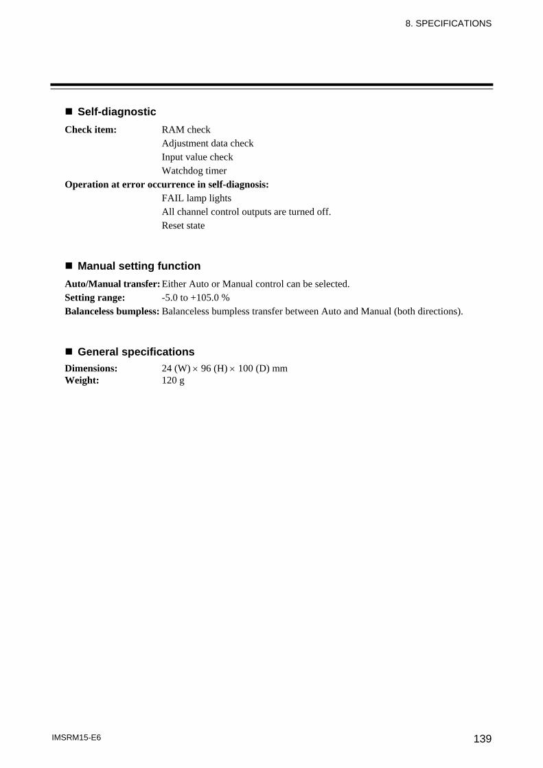
8. SPECIFICATIONS
IMSRM15-E6 139
Self-diagnostic Check item: RAM check Adjustment data check Input value check Watchdog timer Operation at error occurrence in self-diagnosis: FAIL lamp lights All channel control outputs are turned off. Reset state
Manual setting function Auto/Manual transfer: Either Auto or Manual control can be selected. Setting range: -5.0 to +105.0 % Balanceless bumpless: Balanceless bumpless transfer between Auto and Manual (both directions).
General specifications Dimensions: 24 (W) × 96 (H) × 100 (D) mm Weight: 120 g
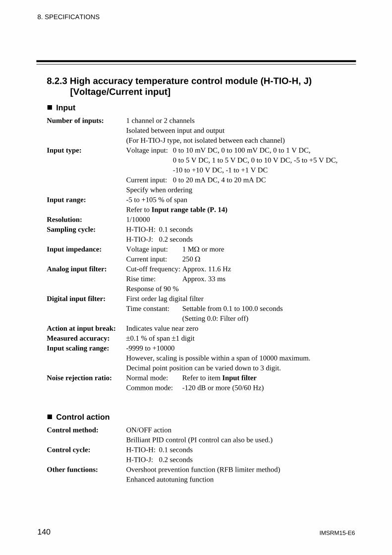
8. SPECIFICATIONS
IMSRM15-E6 140
8.2.3 High accuracy temperature control module (H-TIO-H, J) [Voltage/Current input]
Input Number of inputs: 1 channel or 2 channels Isolated between input and output (For H-TIO-J type, not isolated between each channel) Input type: Voltage input: 0 to 10 mV DC, 0 to 100 mV DC, 0 to 1 V DC, 0 to 5 V DC, 1 to 5 V DC, 0 to 10 V DC, -5 to +5 V DC, -10 to +10 V DC, -1 to +1 V DC Current input: 0 to 20 mA DC, 4 to 20 mA DC Specify when ordering Input range: -5 to +105 % of span Refer to Input range table (P. 14) Resolution: 1/10000 Sampling cycle: H-TIO-H: 0.1 seconds H-TIO-J: 0.2 seconds Input impedance: Voltage input: 1 MΩ or more Current input: 250 Ω
Analog input filter: Cut-off frequency: Approx. 11.6 Hz Rise time: Approx. 33 ms Response of 90 % Digital input filter: First order lag digital filter Time constant: Settable from 0.1 to 100.0 seconds (Setting 0.0: Filter off) Action at input break: Indicates value near zero Measured accuracy: ±0.1 % of span ±1 digit Input scaling range: -9999 to +10000 However, scaling is possible within a span of 10000 maximum. Decimal point position can be varied down to 3 digit. Noise rejection ratio: Normal mode: Refer to item Input filter Common mode: -120 dB or more (50/60 Hz)
Control action Control method: ON/OFF action Brilliant PID control (PI control can also be used.) Control cycle: H-TIO-H: 0.1 seconds H-TIO-J: 0.2 seconds Other functions: Overshoot prevention function (RFB limiter method) Enhanced autotuning function
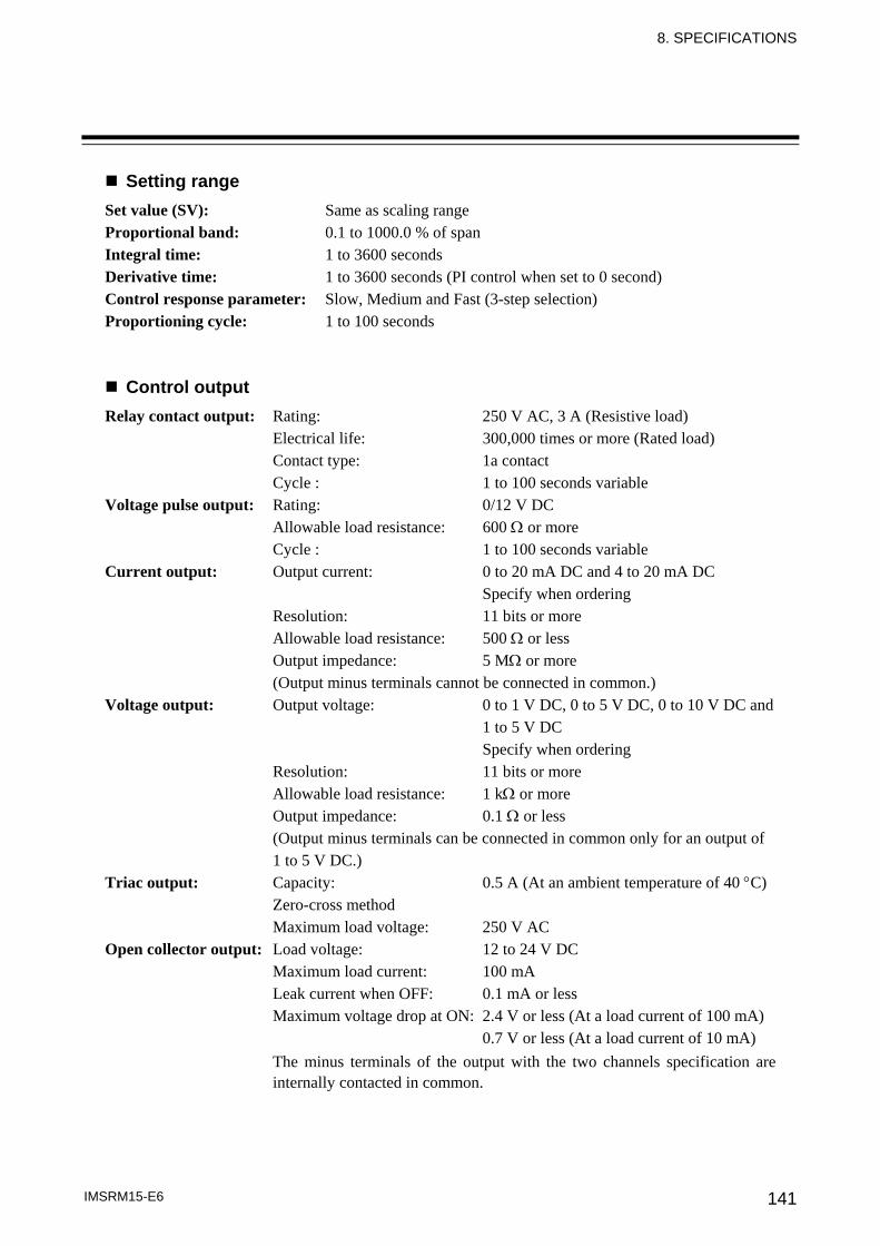
8. SPECIFICATIONS
IMSRM15-E6 141
Setting range Set value (SV): Same as scaling range Proportional band: 0.1 to 1000.0 % of span Integral time: 1 to 3600 seconds Derivative time: 1 to 3600 seconds (PI control when set to 0 second) Control response parameter: Slow, Medium and Fast (3-step selection) Proportioning cycle: 1 to 100 seconds
Control output Relay contact output: Rating: 250 V AC, 3 A (Resistive load) Electrical life: 300,000 times or more (Rated load) Contact type: 1a contact Cycle : 1 to 100 seconds variable Voltage pulse output: Rating: 0/12 V DC Allowable load resistance: 600 Ω or more Cycle : 1 to 100 seconds variable Current output: Output current: 0 to 20 mA DC and 4 to 20 mA DC Specify when ordering Resolution: 11 bits or more Allowable load resistance: 500 Ω or less Output impedance: 5 MΩ or more (Output minus terminals cannot be connected in common.) Voltage output: Output voltage: 0 to 1 V DC, 0 to 5 V DC, 0 to 10 V DC and 1 to 5 V DC Specify when ordering Resolution: 11 bits or more Allowable load resistance: 1 kΩ or more Output impedance: 0.1 Ω or less (Output minus terminals can be connected in common only for an output of 1 to 5 V DC.) Triac output: Capacity: 0.5 A (At an ambient temperature of 40 °C) Zero-cross method Maximum load voltage: 250 V AC Open collector output: Load voltage: 12 to 24 V DC Maximum load current: 100 mA Leak current when OFF: 0.1 mA or less Maximum voltage drop at ON: 2.4 V or less (At a load current of 100 mA) 0.7 V or less (At a load current of 10 mA)
The minus terminals of the output with the two channels specification are internally contacted in common.
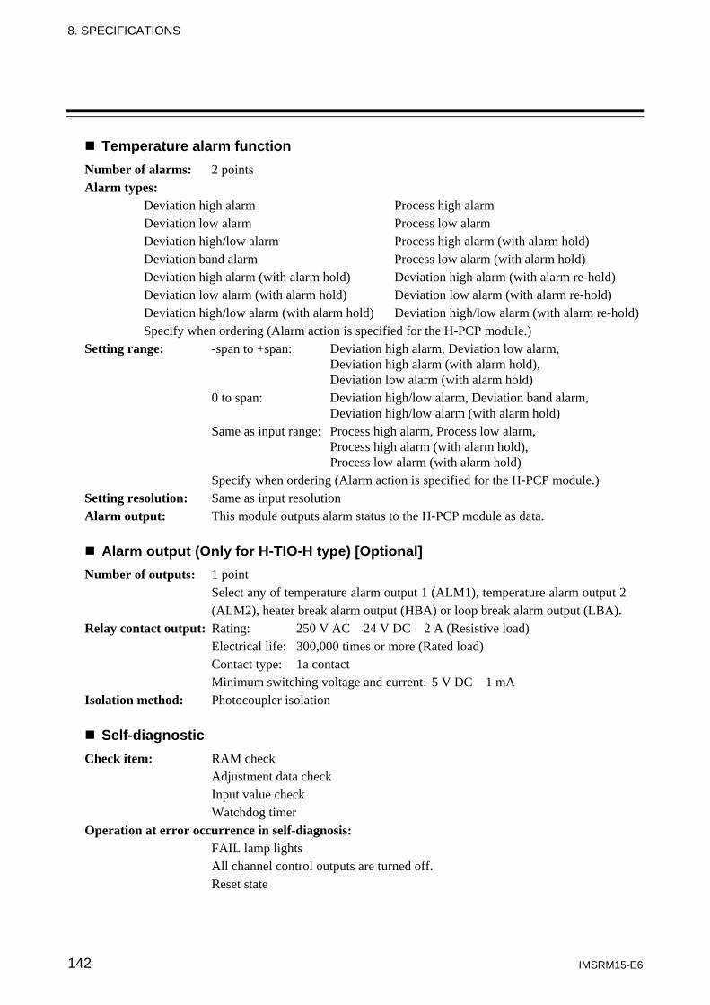
8. SPECIFICATIONS
IMSRM15-E6 142
Temperature alarm function Number of alarms: 2 points
Alarm types: Deviation high alarm Process high alarm Deviation low alarm Process low alarm Deviation high/low alarm Process high alarm (with alarm hold) Deviation band alarm Process low alarm (with alarm hold) Deviation high alarm (with alarm hold) Deviation high alarm (with alarm re-hold) Deviation low alarm (with alarm hold) Deviation low alarm (with alarm re-hold) Deviation high/low alarm (with alarm hold) Deviation high/low alarm (with alarm re-hold) Specify when ordering (Alarm action is specified for the H-PCP module.)
Setting range: -span to +span: Deviation high alarm, Deviation low alarm, Deviation high alarm (with alarm hold), Deviation low alarm (with alarm hold) 0 to span: Deviation high/low alarm, Deviation band alarm, Deviation high/low alarm (with alarm hold) Same as input range: Process high alarm, Process low alarm, Process high alarm (with alarm hold), Process low alarm (with alarm hold) Specify when ordering (Alarm action is specified for the H-PCP module.)
Setting resolution: Same as input resolution Alarm output: This module outputs alarm status to the H-PCP module as data.
Alarm output (Only for H-TIO-H type) [Optional] Number of outputs: 1 point Select any of temperature alarm output 1 (ALM1), temperature alarm output 2 (ALM2), heater break alarm output (HBA) or loop break alarm output (LBA). Relay contact output: Rating: 250 V AC 24 V DC 2 A (Resistive load) Electrical life: 300,000 times or more (Rated load) Contact type: 1a contact Minimum switching voltage and current: 5 V DC 1 mA Isolation method: Photocoupler isolation
Self-diagnostic Check item: RAM check Adjustment data check Input value check Watchdog timer Operation at error occurrence in self-diagnosis: FAIL lamp lights All channel control outputs are turned off. Reset state
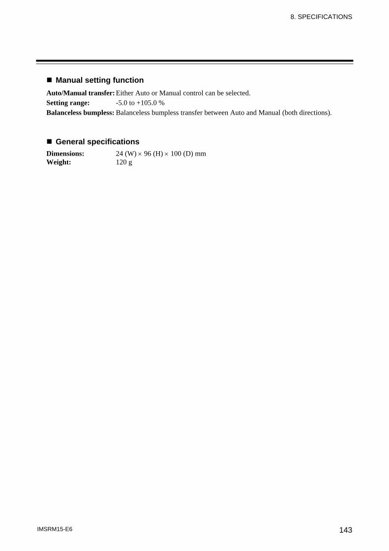
8. SPECIFICATIONS
IMSRM15-E6 143
Manual setting function Auto/Manual transfer: Either Auto or Manual control can be selected. Setting range: -5.0 to +105.0 % Balanceless bumpless: Balanceless bumpless transfer between Auto and Manual (both directions).
General specifications Dimensions: 24 (W) × 96 (H) × 100 (D) mm Weight: 120 g
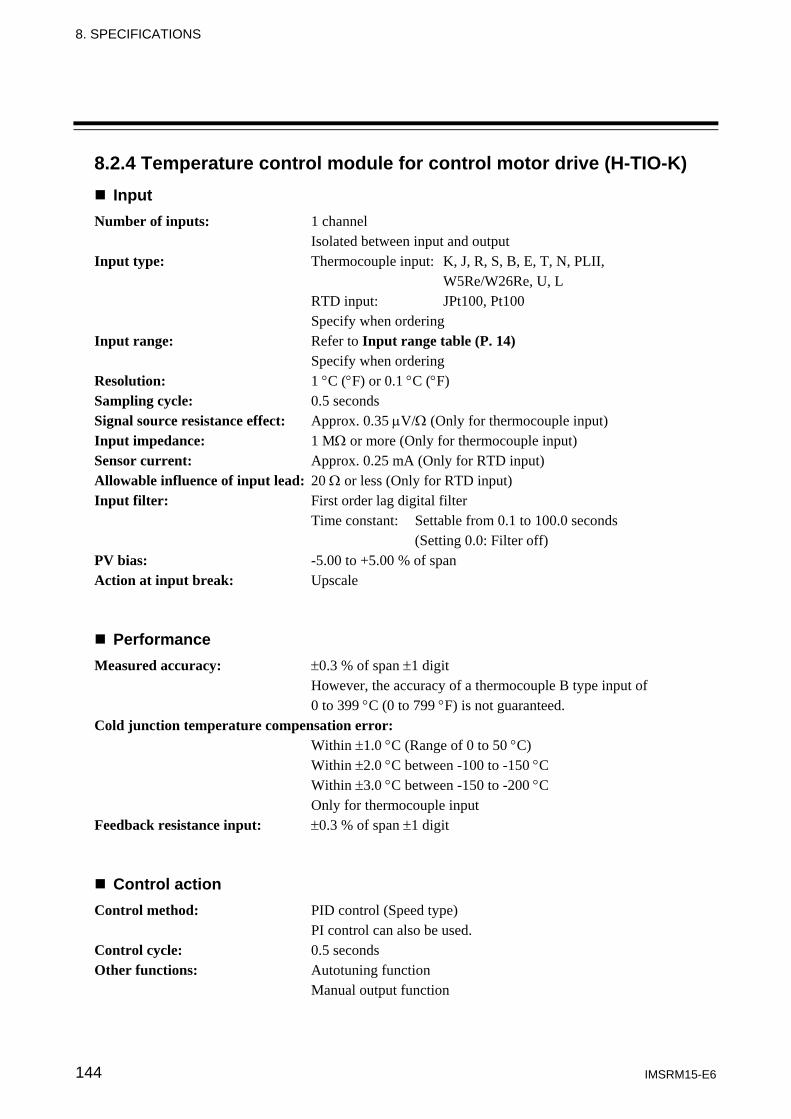
8. SPECIFICATIONS
IMSRM15-E6 144
8.2.4 Temperature control module for control motor drive (H-TIO-K) Input
Number of inputs: 1 channel Isolated between input and output Input type: Thermocouple input: K, J, R, S, B, E, T, N, PLII, W5Re/W26Re, U, L RTD input: JPt100, Pt100 Specify when ordering Input range: Refer to Input range table (P. 14) Specify when ordering Resolution: 1 °C (°F) or 0.1 °C (°F) Sampling cycle: 0.5 seconds Signal source resistance effect: Approx. 0.35 μV/Ω (Only for thermocouple input) Input impedance: 1 MΩ or more (Only for thermocouple input) Sensor current: Approx. 0.25 mA (Only for RTD input) Allowable influence of input lead: 20 Ω or less (Only for RTD input) Input filter: First order lag digital filter Time constant: Settable from 0.1 to 100.0 seconds (Setting 0.0: Filter off) PV bias: -5.00 to +5.00 % of span Action at input break: Upscale
Performance Measured accuracy: ±0.3 % of span ±1 digit
However, the accuracy of a thermocouple B type input of 0 to 399 °C (0 to 799 °F) is not guaranteed.
Cold junction temperature compensation error: Within ±1.0 °C (Range of 0 to 50 °C) Within ±2.0 °C between -100 to -150 °C Within ±3.0 °C between -150 to -200 °C Only for thermocouple input Feedback resistance input: ±0.3 % of span ±1 digit
Control action Control method: PID control (Speed type) PI control can also be used. Control cycle: 0.5 seconds Other functions: Autotuning function Manual output function
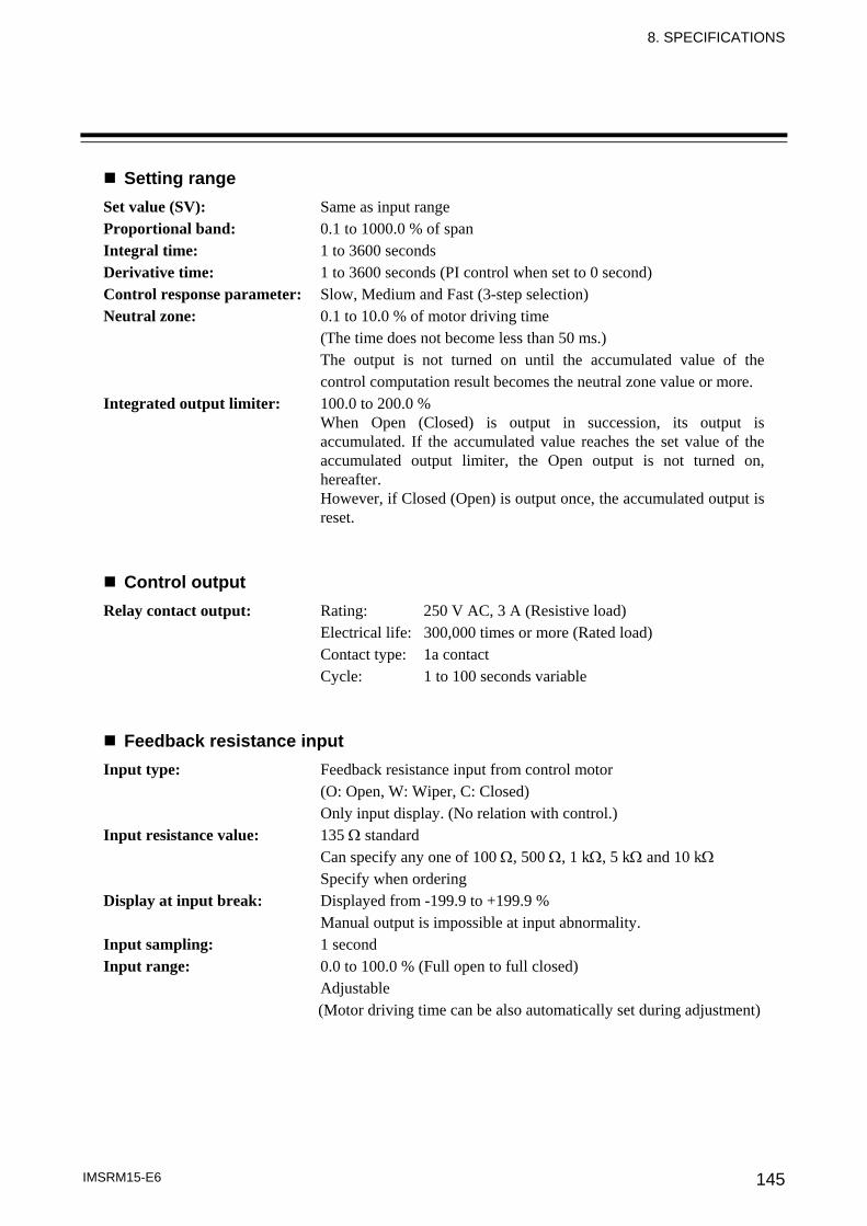
8. SPECIFICATIONS
IMSRM15-E6 145
Setting range Set value (SV): Same as input range Proportional band: 0.1 to 1000.0 % of span Integral time: 1 to 3600 seconds Derivative time: 1 to 3600 seconds (PI control when set to 0 second) Control response parameter: Slow, Medium and Fast (3-step selection) Neutral zone: 0.1 to 10.0 % of motor driving time (The time does not become less than 50 ms.) The output is not turned on until the accumulated value of the control computation result becomes the neutral zone value or more. Integrated output limiter: 100.0 to 200.0 %
When Open (Closed) is output in succession, its output is accumulated. If the accumulated value reaches the set value of the accumulated output limiter, the Open output is not turned on, hereafter. However, if Closed (Open) is output once, the accumulated output is reset.
Control output Relay contact output: Rating: 250 V AC, 3 A (Resistive load) Electrical life: 300,000 times or more (Rated load) Contact type: 1a contact Cycle: 1 to 100 seconds variable
Feedback resistance input Input type: Feedback resistance input from control motor (O: Open, W: Wiper, C: Closed) Only input display. (No relation with control.) Input resistance value: 135 Ω standard Can specify any one of 100 Ω, 500 Ω, 1 kΩ, 5 kΩ and 10 kΩ Specify when ordering Display at input break: Displayed from -199.9 to +199.9 % Manual output is impossible at input abnormality. Input sampling: 1 second Input range: 0.0 to 100.0 % (Full open to full closed) Adjustable (Motor driving time can be also automatically set during adjustment)
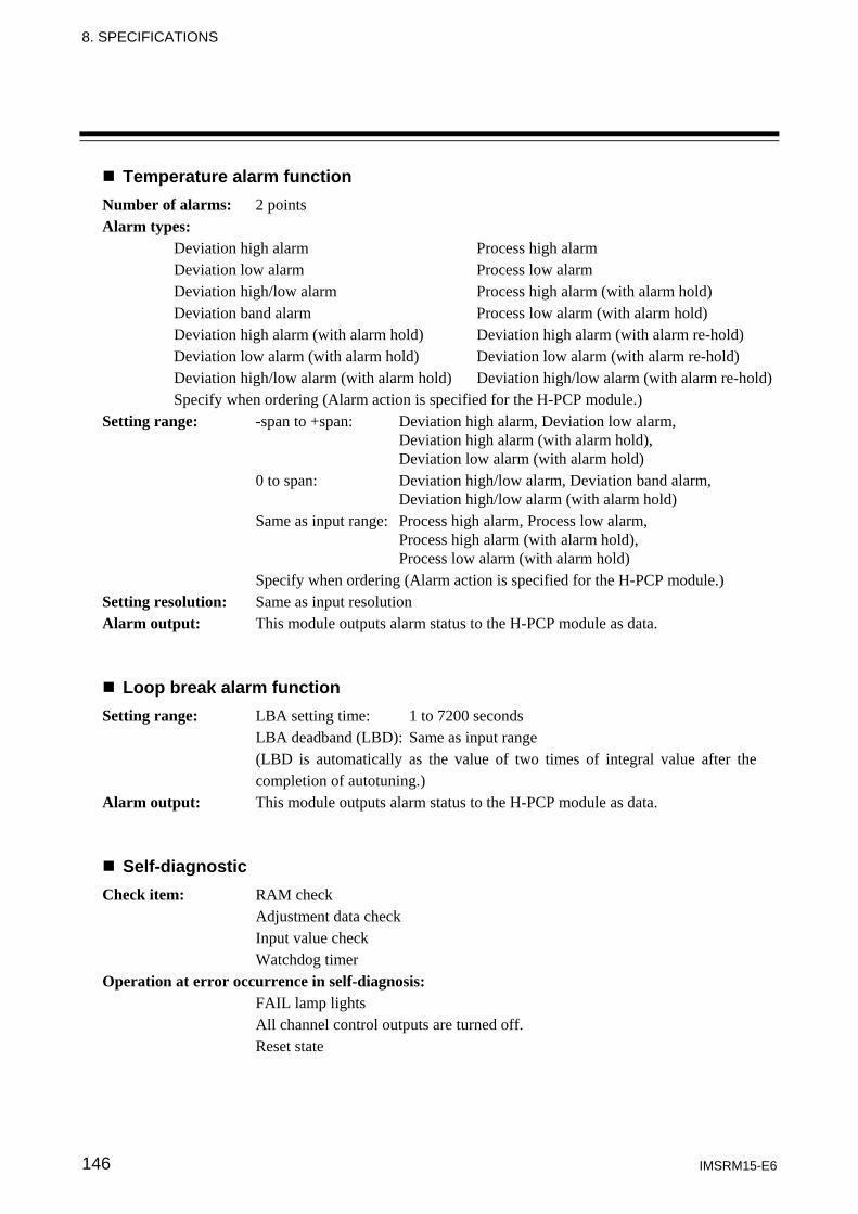
8. SPECIFICATIONS
IMSRM15-E6 146
Temperature alarm function Number of alarms: 2 points
Alarm types: Deviation high alarm Process high alarm Deviation low alarm Process low alarm Deviation high/low alarm Process high alarm (with alarm hold) Deviation band alarm Process low alarm (with alarm hold) Deviation high alarm (with alarm hold) Deviation high alarm (with alarm re-hold) Deviation low alarm (with alarm hold) Deviation low alarm (with alarm re-hold) Deviation high/low alarm (with alarm hold) Deviation high/low alarm (with alarm re-hold) Specify when ordering (Alarm action is specified for the H-PCP module.)
Setting range: -span to +span: Deviation high alarm, Deviation low alarm, Deviation high alarm (with alarm hold), Deviation low alarm (with alarm hold) 0 to span: Deviation high/low alarm, Deviation band alarm, Deviation high/low alarm (with alarm hold) Same as input range: Process high alarm, Process low alarm, Process high alarm (with alarm hold), Process low alarm (with alarm hold) Specify when ordering (Alarm action is specified for the H-PCP module.)
Setting resolution: Same as input resolution Alarm output: This module outputs alarm status to the H-PCP module as data.
Loop break alarm function Setting range: LBA setting time: 1 to 7200 seconds LBA deadband (LBD): Same as input range (LBD is automatically as the value of two times of integral value after the completion of autotuning.) Alarm output: This module outputs alarm status to the H-PCP module as data.
Self-diagnostic Check item: RAM check Adjustment data check Input value check Watchdog timer Operation at error occurrence in self-diagnosis: FAIL lamp lights All channel control outputs are turned off. Reset state
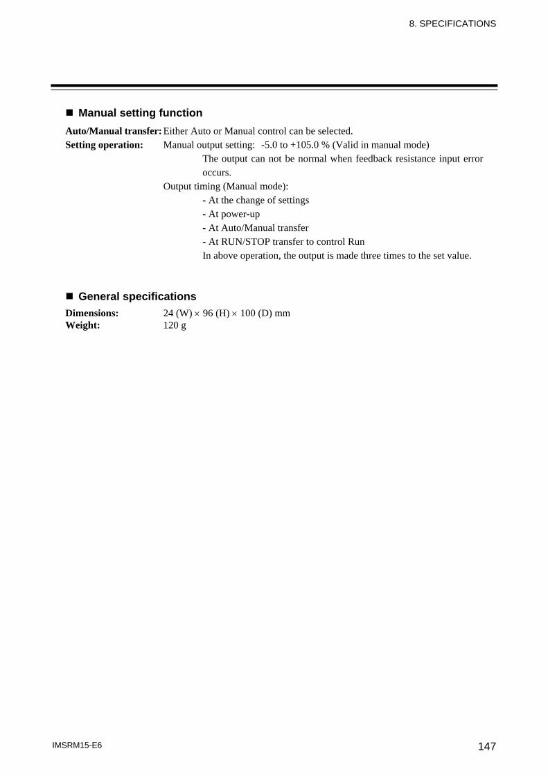
8. SPECIFICATIONS
IMSRM15-E6 147
Manual setting function Auto/Manual transfer: Either Auto or Manual control can be selected. Setting operation: Manual output setting: -5.0 to +105.0 % (Valid in manual mode)
The output can not be normal when feedback resistance input error occurs.
Output timing (Manual mode): - At the change of settings - At power-up - At Auto/Manual transfer - At RUN/STOP transfer to control Run In above operation, the output is made three times to the set value.
General specifications Dimensions: 24 (W) × 96 (H) × 100 (D) mm Weight: 120 g
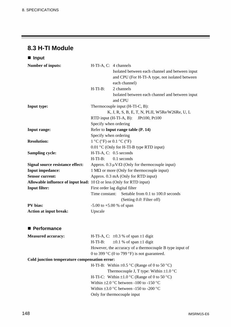
8. SPECIFICATIONS
IMSRM15-E6 148
8.3 H-TI Module Input
Number of inputs: H-TI-A, C: 4 channels Isolated between each channel and between input and CPU (For H-TI-A type, not isolated between each channel) H-TI-B: 2 channels Isolated between each channel and between input and CPU Input type: Thermocouple input (H-TI-C, B): K, J, R, S, B, E, T, N, PLII, W5Re/W26Re, U, L RTD input (H-TI-A, B): JPt100, Pt100 Specify when ordering Input range: Refer to Input range table (P. 14) Specify when ordering Resolution: 1 °C (°F) or 0.1 °C (°F) 0.01 °C (Only for H-TI-B type RTD input) Sampling cycle: H-TI-A, C: 0.5 seconds H-TI-B: 0.1 seconds Signal source resistance effect: Approx. 0.3 μV/Ω (Only for thermocouple input) Input impedance: 1 MΩ or more (Only for thermocouple input) Sensor current: Approx. 0.3 mA (Only for RTD input) Allowable influence of input lead: 10 Ω or less (Only for RTD input) Input filter: First order lag digital filter Time constant: Settable from 0.1 to 100.0 seconds (Setting 0.0: Filter off) PV bias: -5.00 to +5.00 % of span Action at input break: Upscale
Performance Measured accuracy: H-TI-A, C: ±0.3 % of span ±1 digit
H-TI-B: ±0.1 % of span ±1 digit However, the accuracy of a thermocouple B type input of 0 to 399 °C (0 to 799 °F) is not guaranteed.
Cold junction temperature compensation error: H-TI-B: Within ±0.5 °C (Range of 0 to 50 °C) Thermocouple J, T type: Within ±1.0 °C H-TI-C: Within ±1.0 °C (Range of 0 to 50 °C) Within ±2.0 °C between -100 to -150 °C Within ±3.0 °C between -150 to -200 °C Only for thermocouple input
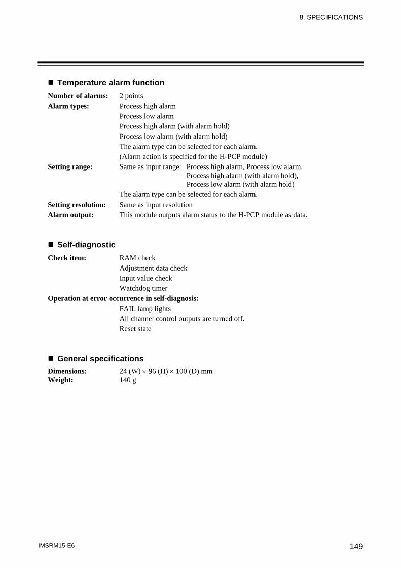
8. SPECIFICATIONS
IMSRM15-E6 149
Temperature alarm function Number of alarms: 2 points
Alarm types: Process high alarm Process low alarm Process high alarm (with alarm hold) Process low alarm (with alarm hold) The alarm type can be selected for each alarm. (Alarm action is specified for the H-PCP module)
Setting range: Same as input range: Process high alarm, Process low alarm, Process high alarm (with alarm hold), Process low alarm (with alarm hold) The alarm type can be selected for each alarm.
Setting resolution: Same as input resolution Alarm output: This module outputs alarm status to the H-PCP module as data.
Self-diagnostic Check item: RAM check Adjustment data check Input value check Watchdog timer Operation at error occurrence in self-diagnosis: FAIL lamp lights All channel control outputs are turned off. Reset state
General specifications Dimensions: 24 (W) × 96 (H) × 100 (D) mm Weight: 140 g
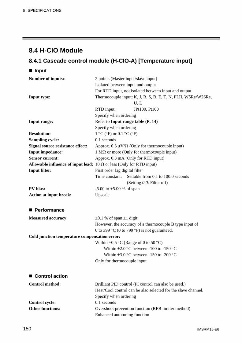
8. SPECIFICATIONS
IMSRM15-E6 150
8.4 H-CIO Module 8.4.1 Cascade control module (H-CIO-A) [Temperature input]
Input Number of inputs:: 2 points (Master input/slave input) Isolated between input and output For RTD input, not isolated between input and output Input type: Thermocouple input: K, J, R, S, B, E, T, N, PLII, W5Re/W26Re, U, L RTD input: JPt100, Pt100 Specify when ordering Input range: Refer to Input range table (P. 14) Specify when ordering Resolution: 1 °C (°F) or 0.1 °C (°F) Sampling cycle: 0.1 seconds Signal source resistance effect: Approx. 0.3 μV/Ω (Only for thermocouple input) Input impedance: 1 MΩ or more (Only for thermocouple input) Sensor current: Approx. 0.3 mA (Only for RTD input) Allowable influence of input lead: 10 Ω or less (Only for RTD input) Input filter: First order lag digital filter Time constant: Settable from 0.1 to 100.0 seconds (Setting 0.0: Filter off) PV bias: -5.00 to +5.00 % of span Action at input break: Upscale
Performance Measured accuracy: ±0.1 % of span ±1 digit
However, the accuracy of a thermocouple B type input of 0 to 399 °C (0 to 799 °F) is not guaranteed.
Cold junction temperature compensation error: Within ±0.5 °C (Range of 0 to 50 °C) Within ±2.0 °C between -100 to -150 °C Within ±3.0 °C between -150 to -200 °C Only for thermocouple input
Control action Control method: Brilliant PID control (PI control can also be used.) Heat/Cool control can be also selected for the slave channel. Specify when ordering Control cycle: 0.1 seconds Other functions: Overshoot prevention function (RFB limiter method) Enhanced autotuning function

8. SPECIFICATIONS
IMSRM15-E6 151
Setting range Set value (SV): Same as input range Heat-side proportional band: 0.1 to 1000.0 % of span Cool-side proportional band: 0.1 to 1000.0 % of span Integral time: 1 to 3600 seconds Derivative time: 1 to 3600 seconds (PI control when set to 0 second) Overlap/Deadband: -10.0 to +10.0 % of span Control response parameter: Slow, Medium and Fast (3-step selection) Proportioning cycle: 1 to 100 seconds
Control output Relay contact output: Rating: 250 V AC, 3 A (Resistive load) Electrical life: 300,000 times or more (Rated load) Contact type: 1a contact Cycle: 1 to 100 seconds variable Voltage pulse output: Rating: 0/12 V DC Allowable load resistance: 600 Ω or more Cycle: 1 to 100 seconds variable Current output: Output current: 0 to 20 mA DC and 4 to 20 mA DC Specify when ordering Resolution: 11 bits or more Allowable load resistance: 500 Ω or less Output impedance: 5 MΩ or more (Output minus terminals cannot be connected in common.) Voltage output: Output voltage: 0 to 1 V DC, 0 to 5 V DC, 0 to 10 V DC and 1 to 5 V DC Specify when ordering Resolution: 11 bits or more Allowable load resistance: 1 kΩ or more Output impedance: 0.1 Ω or less (Output minus terminals can be connected in common only for an output of 1 to 5 V DC.) Triac output: Capacity: 0.5 A (At an ambient temperature of 40 °C) Zero-cross method Maximum load voltage: 250 V AC Open collector output: Load voltage: 12 to 24 V DC Maximum load current: 100 mA Leak current when OFF: 0.1 mA or less Maximum voltage drop at ON: 2.4 V or less (At a load current of 100 mA) 0.7 V or less (At a load current of 10 mA)

8. SPECIFICATIONS
IMSRM15-E6 152
Temperature alarm function Number of alarms: 2 points
Alarm types: Deviation high alarm Process high alarm Deviation low alarm Process low alarm Deviation high/low alarm Process high alarm (with alarm hold) Deviation band alarm Process low alarm (with alarm hold) Deviation high alarm (with alarm hold) Deviation high alarm (with alarm re-hold) Deviation low alarm (with alarm hold) Deviation low alarm (with alarm re-hold) Deviation high/low alarm (with alarm hold) Deviation high/low alarm (with alarm re-hold) Specify when ordering (Alarm action is specified for the H-PCP module.)
Setting range: -span to +span: Deviation high alarm, Deviation low alarm, Deviation high alarm (with alarm hold), Deviation low alarm (with alarm hold) 0 to span: Deviation high/low alarm, Deviation band alarm, Deviation high/low alarm (with alarm hold) Same as input range: Process high alarm, Process low alarm, Process high alarm (with alarm hold), Process low alarm (with alarm hold) Specify when ordering (Alarm action is specified for the H-PCP module.)
Setting resolution: Same as input resolution Alarm output: This module outputs alarm status to the H-PCP module as data.
Loop break alarm function Setting range: LBA setting time: 1 to 7200 seconds LBA deadband (LBD): Same as input range (LBD is automatically as the value of two times of integral value after the completion of autotuning.) Alarm output: This module outputs alarm status to the H-PCP module as data.
Digital input Input type: Dry contact Resistance value at OPEN: 500 kΩ or more Resistance value at CLOSE: 10 Ω or less Number of inputs: 2 points Voltage at OPEN: 12 V DC Contact current: Approx. 3 mA/point Function: Mode selection Isolation method: Photocoupler isolation External connection: Terminals
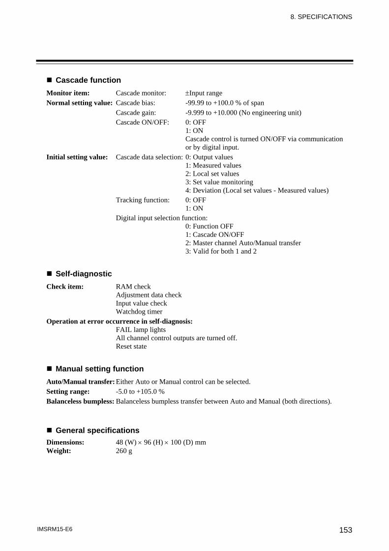
8. SPECIFICATIONS
IMSRM15-E6 153
Cascade function Monitor item: Cascade monitor: ±Input range Normal setting value: Cascade bias: -99.99 to +100.0 % of span Cascade gain: -9.999 to +10.000 (No engineering unit) Cascade ON/OFF: 0: OFF 1: ON Cascade control is turned ON/OFF via communication or by digital input. Initial setting value: Cascade data selection: 0: Output values 1: Measured values 2: Local set values 3: Set value monitoring 4: Deviation (Local set values - Measured values) Tracking function: 0: OFF 1: ON Digital input selection function: 0: Function OFF 1: Cascade ON/OFF 2: Master channel Auto/Manual transfer 3: Valid for both 1 and 2
Self-diagnostic Check item: RAM check Adjustment data check Input value check Watchdog timer Operation at error occurrence in self-diagnosis: FAIL lamp lights All channel control outputs are turned off. Reset state
Manual setting function Auto/Manual transfer: Either Auto or Manual control can be selected. Setting range: -5.0 to +105.0 % Balanceless bumpless: Balanceless bumpless transfer between Auto and Manual (both directions).
General specifications Dimensions: 48 (W) × 96 (H) × 100 (D) mm Weight: 260 g
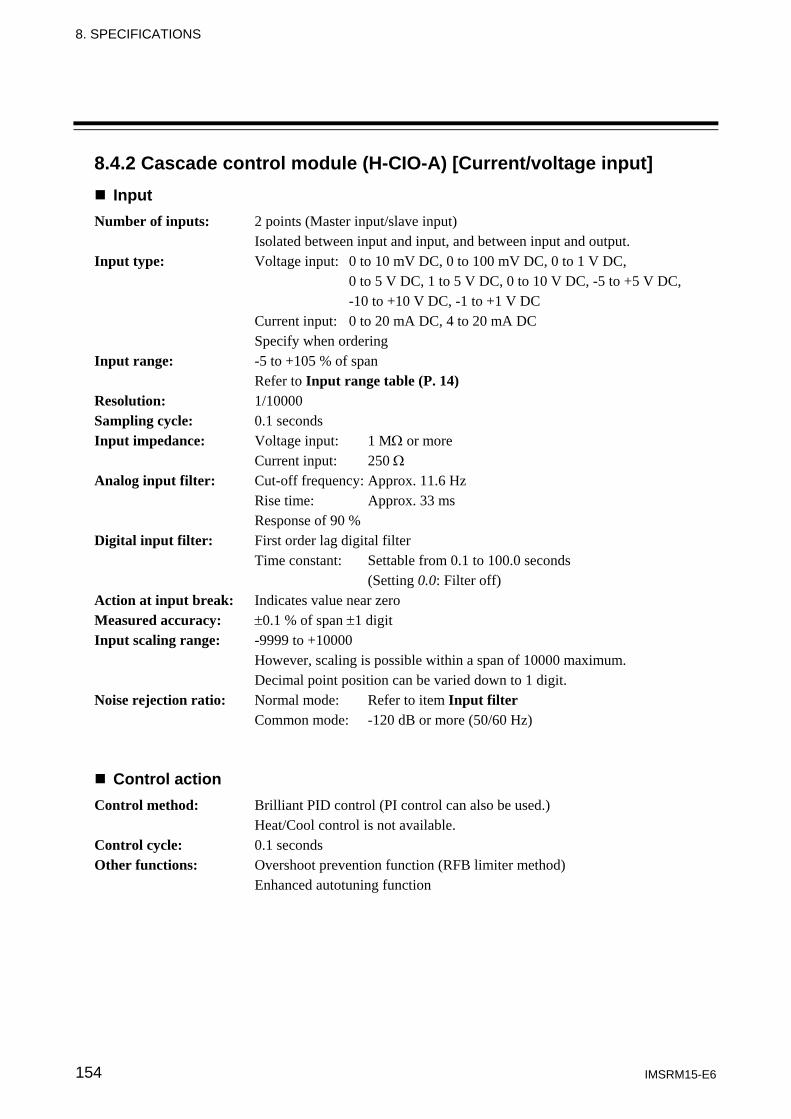
8. SPECIFICATIONS
IMSRM15-E6 154
8.4.2 Cascade control module (H-CIO-A) [Current/voltage input] Input
Number of inputs: 2 points (Master input/slave input) Isolated between input and input, and between input and output. Input type: Voltage input: 0 to 10 mV DC, 0 to 100 mV DC, 0 to 1 V DC, 0 to 5 V DC, 1 to 5 V DC, 0 to 10 V DC, -5 to +5 V DC, -10 to +10 V DC, -1 to +1 V DC Current input: 0 to 20 mA DC, 4 to 20 mA DC Specify when ordering Input range: -5 to +105 % of span Refer to Input range table (P. 14) Resolution: 1/10000 Sampling cycle: 0.1 seconds Input impedance: Voltage input: 1 MΩ or more Current input: 250 Ω
Analog input filter: Cut-off frequency: Approx. 11.6 Hz Rise time: Approx. 33 ms Response of 90 % Digital input filter: First order lag digital filter Time constant: Settable from 0.1 to 100.0 seconds (Setting 0.0: Filter off) Action at input break: Indicates value near zero Measured accuracy: ±0.1 % of span ±1 digit Input scaling range: -9999 to +10000 However, scaling is possible within a span of 10000 maximum. Decimal point position can be varied down to 1 digit. Noise rejection ratio: Normal mode: Refer to item Input filter Common mode: -120 dB or more (50/60 Hz)
Control action Control method: Brilliant PID control (PI control can also be used.) Heat/Cool control is not available. Control cycle: 0.1 seconds Other functions: Overshoot prevention function (RFB limiter method) Enhanced autotuning function
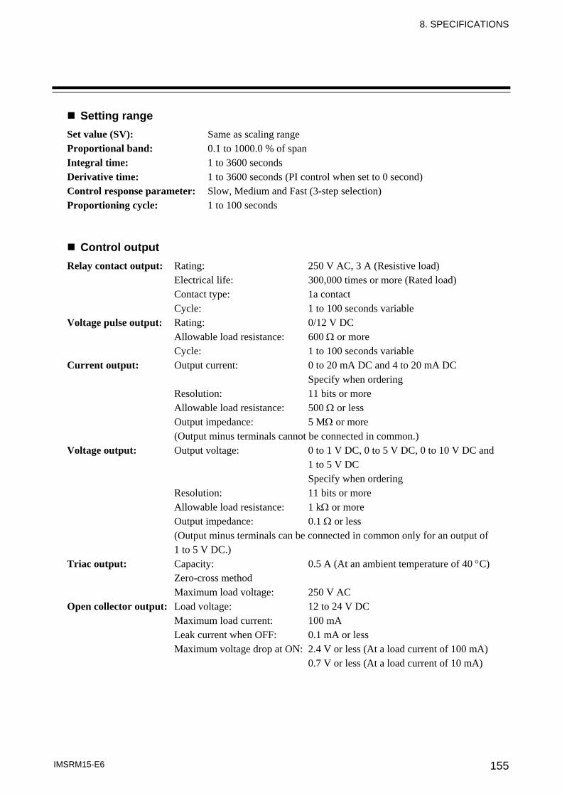
8. SPECIFICATIONS
IMSRM15-E6 155
Setting range Set value (SV): Same as scaling range Proportional band: 0.1 to 1000.0 % of span Integral time: 1 to 3600 seconds Derivative time: 1 to 3600 seconds (PI control when set to 0 second) Control response parameter: Slow, Medium and Fast (3-step selection) Proportioning cycle: 1 to 100 seconds
Control output Relay contact output: Rating: 250 V AC, 3 A (Resistive load) Electrical life: 300,000 times or more (Rated load) Contact type: 1a contact Cycle: 1 to 100 seconds variable Voltage pulse output: Rating: 0/12 V DC Allowable load resistance: 600 Ω or more Cycle: 1 to 100 seconds variable Current output: Output current: 0 to 20 mA DC and 4 to 20 mA DC Specify when ordering Resolution: 11 bits or more Allowable load resistance: 500 Ω or less Output impedance: 5 MΩ or more (Output minus terminals cannot be connected in common.) Voltage output: Output voltage: 0 to 1 V DC, 0 to 5 V DC, 0 to 10 V DC and 1 to 5 V DC Specify when ordering Resolution: 11 bits or more Allowable load resistance: 1 kΩ or more Output impedance: 0.1 Ω or less (Output minus terminals can be connected in common only for an output of 1 to 5 V DC.) Triac output: Capacity: 0.5 A (At an ambient temperature of 40 °C) Zero-cross method Maximum load voltage: 250 V AC Open collector output: Load voltage: 12 to 24 V DC Maximum load current: 100 mA Leak current when OFF: 0.1 mA or less Maximum voltage drop at ON: 2.4 V or less (At a load current of 100 mA) 0.7 V or less (At a load current of 10 mA)

8. SPECIFICATIONS
IMSRM15-E6 156
Temperature alarm function Number of alarms: 2 points
Alarm types: Deviation high alarm Process high alarm Deviation low alarm Process low alarm Deviation high/low alarm Process high alarm (with alarm hold) Deviation band alarm Process low alarm (with alarm hold) Deviation high alarm (with alarm hold) Deviation high alarm (with alarm re-hold) Deviation low alarm (with alarm hold) Deviation low alarm (with alarm re-hold) Deviation high/low alarm (with alarm hold) Deviation high/low alarm (with alarm re-hold) Specify when ordering (Alarm action is specified for the H-PCP module.)
Setting range: -span to +span: Deviation high alarm, Deviation low alarm, Deviation high alarm (with alarm hold), Deviation low alarm (with alarm hold) 0 to span: Deviation high/low alarm, Deviation band alarm, Deviation high/low alarm (with alarm hold) Same as input range: Process high alarm, Process low alarm, Process high alarm (with alarm hold), Process low alarm (with alarm hold) Specify when ordering (Alarm action is specified for the H-PCP module.)
Setting resolution: Same as input resolution Alarm output: This module outputs alarm status to the H-PCP module as data.
Loop break alarm function Setting range: LBA setting time: 1 to 7200 seconds LBA deadband (LBD): Same as input range (LBD is automatically as the value of two times of integral value after the completion of autotuning.) Alarm output: This module outputs alarm status to the H-PCP module as data.
Digital input Input type: Dry contact Resistance value at OPEN: 500 kΩ or more Resistance value at CLOSE: 10 Ω or less Number of inputs: 2 points Voltage at OPEN: 12 V DC Contact current: Approx. 3 mA/point Function: Mode selection Isolation method: Photocoupler isolation External connection: Terminals

8. SPECIFICATIONS
IMSRM15-E6 157
Cascade function Monitor item: Cascade monitor: ±Input range Normal setting value: Cascade bias: -99.99 to +100.0 % of span Cascade gain: -9.999 to +10.000 (No engineering unit) Cascade ON/OFF: 0: OFF 1: ON Cascade control is turned ON/OFF via communication or by digital input. Initial setting value: Cascade data selection: 0: Output values 1: Measured values 2: Local set values 3: Set value monitoring 4: Deviation (Local set values - Measured values) Tracking function: 0: OFF 1: ON Digital input selection function: 0: Function OFF 1: Cascade ON/OFF 2: Master channel Auto/Manual transfer 3: Valid for both 1 and 2
Self-diagnostic Check item: RAM check Adjustment data check Input value check Watchdog timer Operation at error occurrence in self-diagnosis: FAIL lamp lights All channel control outputs are turned off. Reset state
Manual setting function Auto/Manual transfer: Either Auto or Manual control can be selected. Setting range: -5.0 to +105.0 % Balanceless bumpless: Balanceless bumpless transfer between Auto and Manual (both directions).
General specifications Dimensions: 48 (W) × 96 (H) × 100 (D) mm Weight: 260 g
8. SPECIFICATIONS
IMSRM15-E6 158
8.5 H-CT Module Input
Input type: Current transformer input (CT)
Number of inputs: 6 points
Number of common points: 3 points (1-2 channel/common, 3-4 channel/common, 5-6 channel/common) Isolation method: Photocoupler isolation Input current: 0 to 30 A: CTL-6-P-N 0 to 100 A: CTL-12-S56-10L-N Specify when ordering (Current transformer is sold separately)
Accuracy of heater current measurement: 5 % of input value or ±2 A (The value whichever is greater)
Heater break alarm function Setting range: 0.0 to 100.0 A Corresponding channel setting: 1 to 20 channels (Same channel can be set) Alarm output: This module outputs alarm status to the H-PCP module as data.
Self-diagnostic Check item: RAM check Watchdog timer Operation at error occurrence in self-diagnosis: FAIL lamp lights Reset state
General specifications Dimensions: 24 (W) × 96 (H) × 100 (D) mm Weight: 120 g
8. SPECIFICATIONS
IMSRM15-E6 159
8.6 H-DI Module 8.6.1 Digital input module (H-DI-A)
Input Input type: Source type
Number of inputs: 8 points
Rated input voltage: 24 V DC Input voltage range: 21.6 to 26.4 V DC Rated input current: 6.7 mA/point (24 V DC) Input impedance: 3.6 kΩ Input operation voltage: ON voltage: 18.5 V DC OFF voltage: 9.0 V DC Number of common points: 4 points/common Isolation method: Photocoupler isolation External connection: Terminals
Functions Memory area transfer: Possible to transfer eight memory area. Control RUN/STOP transfer: Possible to transfer RUN/STOP of temperature control. Alarm interlock release: Possible to release the alarm interlock on all channels.
Self-diagnostic Check item: RAM check Watchdog timer Operation at error occurrence in self-diagnosis: FAIL lamp lights Reset state
General specifications Dimensions: 24 (W) × 96 (H) × 100 (D) mm Weight: 120 g
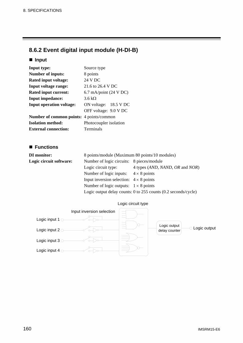
8. SPECIFICATIONS
IMSRM15-E6 160
8.6.2 Event digital input module (H-DI-B) Input
Input type: Source type
Number of inputs: 8 points
Rated input voltage: 24 V DC Input voltage range: 21.6 to 26.4 V DC Rated input current: 6.7 mA/point (24 V DC) Input impedance: 3.6 kΩ Input operation voltage: ON voltage: 18.5 V DC OFF voltage: 9.0 V DC Number of common points: 4 points/common Isolation method: Photocoupler isolation External connection: Terminals
Functions DI monitor: 8 points/module (Maximum 80 points/10 modules) Logic circuit software: Number of logic circuits: 8 pieces/module Logic circuit type: 4 types (AND, NAND, OR and NOR) Number of logic inputs: 4 × 8 points Input inversion selection: 4 × 8 points Number of logic outputs: 1 × 8 points Logic output delay counts: 0 to 255 counts (0.2 seconds/cycle)
Logic input 1
Logic input 2
Logic input 3
Logic input 4
Input inversion selection
Logic circuit type
Logic output delay counter Logic output
8. SPECIFICATIONS
IMSRM15-E6 161
Logic input type: Event DI input: 1 to 80 CH Event DI logic output: 1 to 80 CH Event DO output: 1 to 72 CH Temperature alarm 1: 1 to 18 CH Temperature alarm 2: 1 to 18 CH TIO burnout status: 1 to 18 CH TIO heater break status: 1 to 18 CH TIO loop break status: 1 to 18 CH AI alarm 1: 1 to 36 CH AI alarm 2: 1 to 36 CH TI alarm 1: 1 to 36 CH TI alarm 2: 1 to 36 CH TI burnout status: 1 to 36 CH H-PCP module error status: Provided/Not provided TIO temperature rise completion status: Completed/Not completed TIO’s PID/AT logical add: Normally all channels are under control/ Either of channels are under autotuning
Self-diagnostic Check item: RAM check Watchdog timer Operation at error occurrence in self-diagnosis: FAIL lamp lights Reset state
General specifications Dimensions: 24 (W) × 96 (H) × 100 (D) mm Weight: 120 g
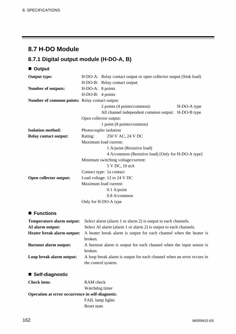
8. SPECIFICATIONS
IMSRM15-E6 162
8.7 H-DO Module 8.7.1 Digital output module (H-DO-A, B)
Output Output type: H-DO-A: Relay contact output or open collector output (Sink load) H-DO-B: Relay contact output Number of outputs: H-DO-A: 8 points H-DO-B: 4 points Number of common points: Relay contact output: 2 points (4 points/common): H-DO-A type All channel independent common output: H-DO-B type Open collector output: 1 point (8 points/common) Isolation method: Photocoupler isolation Relay contact output: Rating: 250 V AC, 24 V DC Maximum load current: 1 A/point (Resistive load) 4 A/common (Resistive load) [Only for H-DO-A type] Minimum switching voltage/current: 5 V DC, 10 mA Contact type: 1a contact Open collector output: Load voltage: 12 to 24 V DC Maximum load current: 0.1 A/point 0.8 A/common Only for H-DO-A type
Functions Temperature alarm output: Select alarm (alarm 1 or alarm 2) is output to each channels. AI alarm output: Select AI alarm (alarm 1 or alarm 2) is output to each channels. Heater break alarm output: A heater break alarm is output for each channel when the heater is
broken. Burnout alarm output: A burnout alarm is output for each channel when the input sensor is
broken. Loop break alarm output: A loop break alarm is output for each channel when an error occurs in
the control system.
Self-diagnostic Check item: RAM check Watchdog timer Operation at error occurrence in self-diagnosis: FAIL lamp lights Reset state
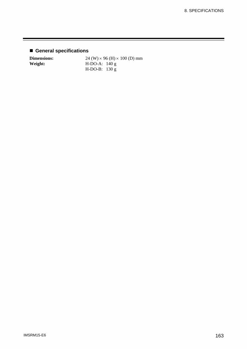
8. SPECIFICATIONS
IMSRM15-E6 163
General specifications Dimensions: 24 (W) × 96 (H) × 100 (D) mm Weight: H-DO-A: 140 g H-DO-B: 130 g
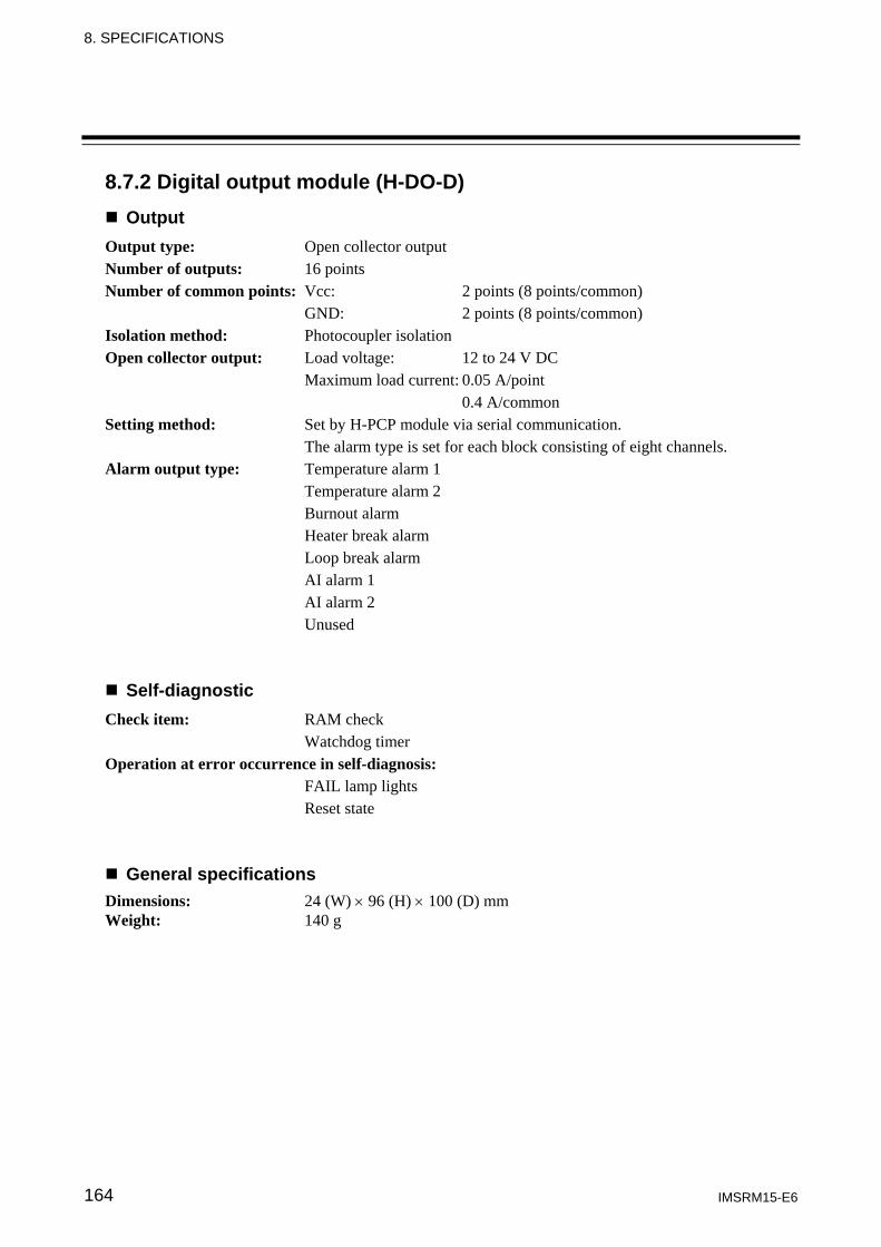
8. SPECIFICATIONS
IMSRM15-E6 164
8.7.2 Digital output module (H-DO-D) Output
Output type: Open collector output Number of outputs: 16 points Number of common points: Vcc: 2 points (8 points/common) GND: 2 points (8 points/common) Isolation method: Photocoupler isolation Open collector output: Load voltage: 12 to 24 V DC Maximum load current: 0.05 A/point 0.4 A/common Setting method: Set by H-PCP module via serial communication. The alarm type is set for each block consisting of eight channels. Alarm output type: Temperature alarm 1 Temperature alarm 2 Burnout alarm Heater break alarm Loop break alarm AI alarm 1 AI alarm 2 Unused
Self-diagnostic Check item: RAM check Watchdog timer Operation at error occurrence in self-diagnosis: FAIL lamp lights Reset state
General specifications Dimensions: 24 (W) × 96 (H) × 100 (D) mm Weight: 140 g
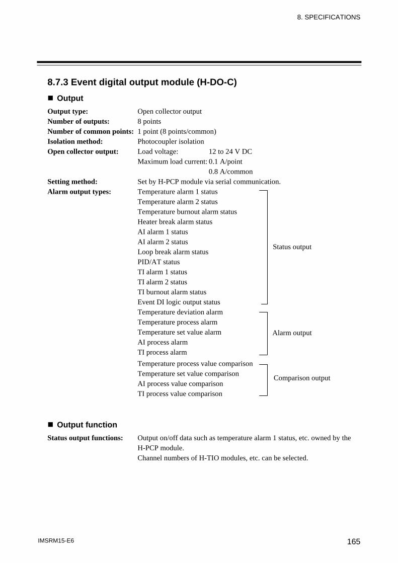
8. SPECIFICATIONS
IMSRM15-E6 165
8.7.3 Event digital output module (H-DO-C) Output
Output type: Open collector output Number of outputs: 8 points Number of common points: 1 point (8 points/common) Isolation method: Photocoupler isolation Open collector output: Load voltage: 12 to 24 V DC Maximum load current: 0.1 A/point 0.8 A/common Setting method: Set by H-PCP module via serial communication. Alarm output types: Temperature alarm 1 status Temperature alarm 2 status Temperature burnout alarm status Heater break alarm status AI alarm 1 status AI alarm 2 status Loop break alarm status PID/AT status TI alarm 1 status TI alarm 2 status TI burnout alarm status Event DI logic output status
Temperature deviation alarm Temperature process alarm Temperature set value alarm AI process alarm TI process alarm Temperature process value comparison Temperature set value comparison AI process value comparison TI process value comparison
Output function Status output functions: Output on/off data such as temperature alarm 1 status, etc. owned by the
H-PCP module. Channel numbers of H-TIO modules, etc. can be selected.
Status output
Alarm output
Comparison output
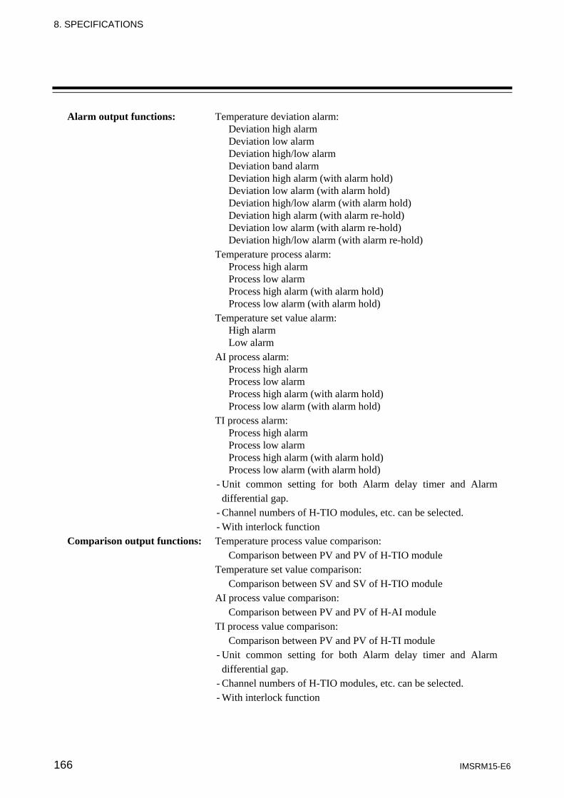
8. SPECIFICATIONS
IMSRM15-E6 166
Alarm output functions: Temperature deviation alarm: Deviation high alarm Deviation low alarm Deviation high/low alarm Deviation band alarm Deviation high alarm (with alarm hold) Deviation low alarm (with alarm hold) Deviation high/low alarm (with alarm hold) Deviation high alarm (with alarm re-hold) Deviation low alarm (with alarm re-hold) Deviation high/low alarm (with alarm re-hold) Temperature process alarm: Process high alarm Process low alarm Process high alarm (with alarm hold) Process low alarm (with alarm hold) Temperature set value alarm: High alarm Low alarm AI process alarm: Process high alarm Process low alarm Process high alarm (with alarm hold) Process low alarm (with alarm hold) TI process alarm: Process high alarm Process low alarm Process high alarm (with alarm hold) Process low alarm (with alarm hold)
- Unit common setting for both Alarm delay timer and Alarm differential gap.
- Channel numbers of H-TIO modules, etc. can be selected. - With interlock function
Comparison output functions: Temperature process value comparison: Comparison between PV and PV of H-TIO module Temperature set value comparison: Comparison between SV and SV of H-TIO module AI process value comparison: Comparison between PV and PV of H-AI module TI process value comparison: Comparison between PV and PV of H-TI module
- Unit common setting for both Alarm delay timer and Alarm differential gap.
- Channel numbers of H-TIO modules, etc. can be selected. - With interlock function
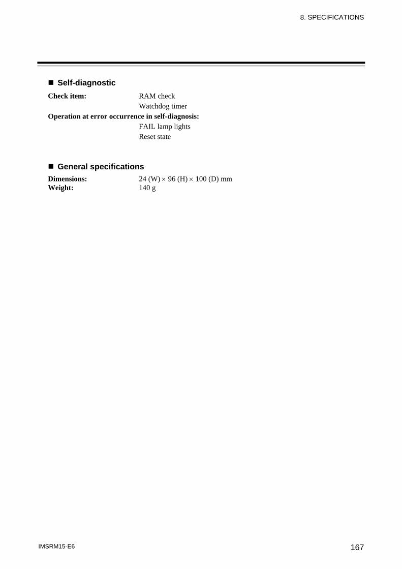
8. SPECIFICATIONS
IMSRM15-E6 167
Self-diagnostic Check item: RAM check Watchdog timer Operation at error occurrence in self-diagnosis: FAIL lamp lights Reset state
General specifications Dimensions: 24 (W) × 96 (H) × 100 (D) mm Weight: 140 g
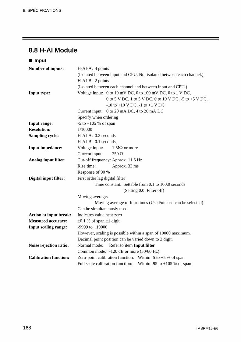
8. SPECIFICATIONS
IMSRM15-E6 168
8.8 H-AI Module Input
Number of inputs: H-AI-A: 4 points (Isolated between input and CPU. Not isolated between each channel.) H-AI-B: 2 points (Isolated between each channel and between input and CPU.) Input type: Voltage input: 0 to 10 mV DC, 0 to 100 mV DC, 0 to 1 V DC, 0 to 5 V DC, 1 to 5 V DC, 0 to 10 V DC, -5 to +5 V DC, -10 to +10 V DC, -1 to +1 V DC Current input: 0 to 20 mA DC, 4 to 20 mA DC Specify when ordering Input range: -5 to +105 % of span Resolution: 1/10000 Sampling cycle: H-AI-A: 0.2 seconds H-AI-B: 0.1 seconds Input impedance: Voltage input: 1 MΩ or more Current input: 250 Ω
Analog input filter: Cut-off frequency: Approx. 11.6 Hz Rise time: Approx. 33 ms Response of 90 % Digital input filter: First order lag digital filter Time constant: Settable from 0.1 to 100.0 seconds (Setting 0.0: Filter off) Moving average: Moving average of four times (Used/unused can be selected) Can be simultaneously used. Action at input break: Indicates value near zero Measured accuracy: ±0.1 % of span ±1 digit Input scaling range: -9999 to +10000 However, scaling is possible within a span of 10000 maximum. Decimal point position can be varied down to 3 digit. Noise rejection ratio: Normal mode: Refer to item Input filter Common mode: -120 dB or more (50/60 Hz) Calibration function: Zero-point calibration function: Within -5 to +5 % of span Full scale calibration function: Within -95 to +105 % of span
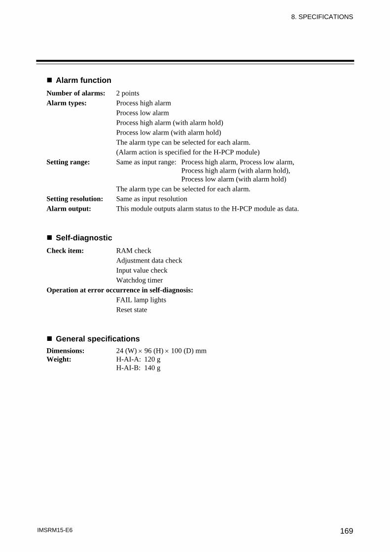
8. SPECIFICATIONS
IMSRM15-E6 169
Alarm function Number of alarms: 2 points
Alarm types: Process high alarm Process low alarm Process high alarm (with alarm hold) Process low alarm (with alarm hold) The alarm type can be selected for each alarm. (Alarm action is specified for the H-PCP module)
Setting range: Same as input range: Process high alarm, Process low alarm, Process high alarm (with alarm hold), Process low alarm (with alarm hold) The alarm type can be selected for each alarm.
Setting resolution: Same as input resolution Alarm output: This module outputs alarm status to the H-PCP module as data.
Self-diagnostic Check item: RAM check Adjustment data check Input value check Watchdog timer Operation at error occurrence in self-diagnosis: FAIL lamp lights Reset state
General specifications Dimensions: 24 (W) × 96 (H) × 100 (D) mm Weight: H-AI-A: 120 g H-AI-B: 140 g
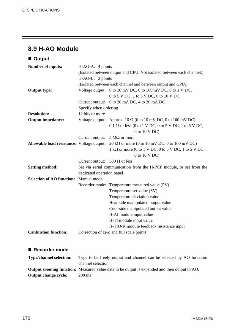
8. SPECIFICATIONS
IMSRM15-E6 170
8.9 H-AO Module Output
Number of inputs: H-AO-A: 4 points (Isolated between output and CPU. Not isolated between each channel.) H-AO-B: 2 points (Isolated between each channel and between output and CPU.) Output type: Voltage output: 0 to 10 mV DC, 0 to 100 mV DC, 0 to 1 V DC, 0 to 5 V DC, 1 to 5 V DC, 0 to 10 V DC Current output: 0 to 20 mA DC, 4 to 20 mA DC Specify when ordering Resolution: 12 bits or more Output impedance: Voltage output: Approx. 10 Ω (0 to 10 mV DC, 0 to 100 mV DC) 0.1 Ω or less (0 to 1 V DC, 0 to 5 V DC, 1 to 5 V DC, 0 to 10 V DC) Current output: 5 MΩ or more Allowable load resistance: Voltage output: 20 kΩ or more (0 to 10 mV DC, 0 to 100 mV DC) 1 kΩ or more (0 to 1 V DC, 0 to 5 V DC, 1 to 5 V DC, 0 to 10 V DC) Current output: 500 Ω or less Setting method: Set via serial communication from the H-PCP module, or set from the
dedicated operation panel. Selection of AO function: Manual mode Recorder mode: Temperature measured value (PV) Temperature set value (SV) Temperature deviation value Heat-side manipulated output value Cool-side manipulated output value H-AI module input value H-TI module input value H-TIO-K module feedback resistance input Calibration function: Correction of zero and full scale points
Recorder mode Type/channel selection: Type to be freely output and channel can be selected by AO function/
channel selection. Output zooming function: Measured value data to be output is expanded and then output to AO. Output change cycle: 200 ms
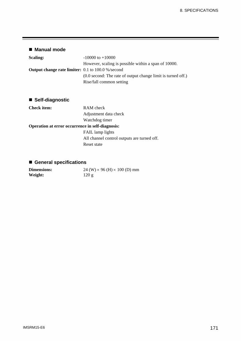
8. SPECIFICATIONS
IMSRM15-E6 171
Manual mode Scaling: -10000 to +10000 However, scaling is possible within a span of 10000. Output change rate limiter: 0.1 to 100.0 %/second (0.0 second: The rate of output change limit is turned off.) Rise/fall common setting
Self-diagnostic Check item: RAM check Adjustment data check Watchdog timer Operation at error occurrence in self-diagnosis: FAIL lamp lights All channel control outputs are turned off. Reset state
General specifications Dimensions: 24 (W) × 96 (H) × 100 (D) mm Weight: 120 g

8. SPECIFICATIONS
IMSRM15-E6 172
8.10 Common Specifications Control unit
Power supply voltage: 90 to 132 V AC (50/60 Hz) [Including power supply voltage variation] (Rating: 100 to 120 V AC) 180 to 264 V AC (50/60 Hz) [Including power supply voltage variation] (Rating: 200 to 240 V AC) 21.6 to 26.4 V DC [Including power supply voltage variation] (Rating: 24 V DC) Insulation resistance: Between power and ground terminals: 20 MΩ or more at 500 V DC Between input/output and ground terminals: 20 MΩ or more at 500 V DC Withstand voltage: Between power and ground terminals: 1500 V AC for 1 minute Between input/output and ground terminals: 1000 V AC for 1 minute Withstand noise: 1500 V (peak to peak) Pulse width: 1 μs Rise time: 1 ns By noise simulator Withstand vibration: Frequency: 5 to 9 Hz Amplitude: 1.5 mm Frequency: 9 to 150 Hz Acceleration: 5.0 m/s Sweep speed: 10 Hz/min Vibration director: Front and back, Right and left, Up and down (Three directions) Vibration time: 1 hour, all directions Power failure effect: No influence even under power failure of 20 ms or less. Ambient temperature range: 0 to 50 °C Ambient humidity range: 45 to 85 %RH (Absolute humidity: MAX.W.C 29.3 g/m3 dry air at 101.3 kPa) Operating environment: No corrosive gases, no large amounts of dust or particulates. Storage temperature range: -20 to +70 °C Storage humidity range: 95 %RH or less (Non condensing) Grounding resistance: 100 Ω or less Cooling method: Natural cooling

The first edition: MAR. 1996 The sixth edition: MAR. 2013 [IMQ00]

IMSRM15-E6 MAR. 2013
RKC INSTRUMENT INC.
HEADQUARTERS: 16-6, KUGAHARA 5-CHOME, OHTA-KU TOKYO 146-8515 JAPAN PHONE: 03-3751-9799 (+81 3 3751 9799) FAX: 03-3751-8585 (+81 3 3751 8585) E-mail: [email protected] Website: http://www.rkcinst.com/
R


![Digital Controller CB100/CB400 CB500/CB700 CB900400,500,700,900_modbu… · IMCB14-E1 CB100/CB400 CB500/CB700 CB900 [Z-1021] MODBUS Communication Instruction Manual ® RKC INSTRUMENT](https://img.pdfslide.us/doc/110x75/5b08e0457f8b9ac90f8d3596/digital-controller-cb100cb400-cb500cb700-400500700900modbuimcb14-e1-cb100cb400.jpg)


![SRZ Instruction Manual [For PLC Communication] - rkc instrument inc](https://img.pdfslide.us/doc/110x75/620aed76a0970e59cd732db4/srz-instruction-manual-for-plc-communication-rkc-instrument-inc.jpg)