Embed Size (px)
Citation preview

20
D1 D2 1N914 diodes 2D3 Red LED 1
9V Battery Holder 1P1 PC mount microphone jack 1P5 2-position header 1
Jumper 1Headset Microphone 13V Coin Battery 1
2/56 Hex nuts, Screws & Lock washers 2 each7-pin headers (male and female) 1 each10-pin headers (male and female) 1 each
1
Images SI Inc.Staten Island NY 10312718.966.3694 voice718.966.3695 fax
http://www.imagesco.com
SR-06/SR-07Speech Recognition Kit
Construction Manual& User Guide
2
Table of Contents
IntroductionApplicationsCircuit ConstructionChip InstallationDisplay Board ConstructionMain Circuit Board ConstructionKeypad ConstructionNon-Volatile Memory BackupSelecting Word Length & Vocabulary SizeUsing the Speech Recognition CircuitKeypad UseTraining Words for Recognition
Error CodesClearing MemoryChanging & Erasing WordsSimulated Independent Recognition
Rhyming wordsVoice Stress & ExcitementInterfacing to the outside WorldError CodesInterface CircuitVoice Security SystemCPU ModeAUI Aural User InterfaceLearning to ListenSpeaker Dependent / Speaker IndependentRecognition StyleMore on the HM2007Parts List
Pages
33
5579991010111212121213141414151717171718181920
19
Maximum word length 1.92 seconds (20 word)Microphone supportManual and CPU modes availableResponse time less than 300 milliseconds5V power supply
More information on the HM2007 chip is available in theHM2007 data booklet (DS-HM2007).
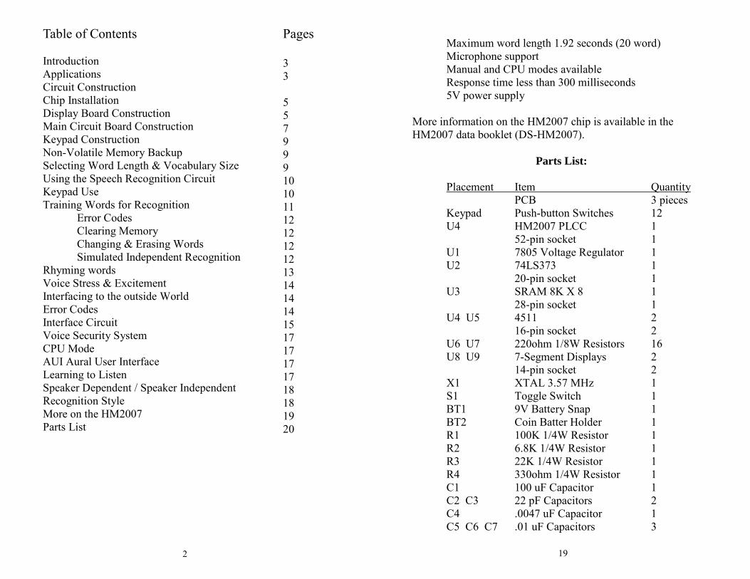
Parts List:
Placement Item QuantityPCB 3 pieces
Keypad Push-button Switches 12U4 HM2007 PLCC 1
52-pin socket 1U1 7805 Voltage Regulator 1U2 74LS373 1
20-pin socket 1U3 SRAM 8K X 8 1
28-pin socket 1U4 U5 4511 2
16-pin socket 2U6 U7 220ohm 1/8W Resistors 16U8 U9 7-Segment Displays 2
14-pin socket 2X1 XTAL 3.57 MHz 1S1 Toggle Switch 1BT1 9V Battery Snap 1BT2 Coin Batter Holder 1R1 100K 1/4W Resistor 1R2 6.8K 1/4W Resistor 1R3 22K 1/4W Resistor 1R4 330ohm 1/4W Resistor 1C1 100 uF Capacitor 1C2 C3 22 pF Capacitors 2C4 .0047 uF Capacitor 1C5 C6 C7 .01 uF Capacitors 3
18
require speaker independent voice recognition systems.
Recognition Style
In addition to the speaker dependent/independent classification,speech recognition also contends with the style of speech it canrecognize. They are three styles of speech: isolated, connectedand continuous.
Isolated. Words are spoken separately or isolated. This is themost common speech recognition system available today. Theuser must pause between each word or command spoken.
Connected. This is a half way point between isolated word andcontinuous speech recognition. It permits users to speak multiplewords. The HM2007 can be set up to identify words or phrases1.92 seconds in length. This reduces the word recognition diction-ary number to 20.
Continuous. This is the natural conversational speech we use toin everyday life. It is extremely difficult for a recognizer to siftthrough the sound as the words tend to merge together. For in-stance, "Hi, how are you doing?" to a computer sounds like"Hi,.howyadoin" Continuous speech recognition systems are onthe market and are under continual development.
More On The HM2007 Chip
The HM2007 is a CMOS voice recognition LSI (Large Scale Inte-gration) circuit. The chip contains an analog front end, voiceanalysis, regulation, and system control functions. The chip maybe used in a stand alone or CPU connected.
Features:Single chip voice recognition CMOS LSISpeaker dependentExternal RAM supportMaximum 40 word recognition (.96 second)
3
Introduction:
The speech recognition kit is a complete easy to build program-mable speech recognition circuit. Programmable, in the sensethat you train the words (or vocal utterances) you want the cir-cuit to recognize. This kit allows you to experiment with manyfacets of speech recognition technology.
Features of the kit include:
Self-contained stand alone speech recognition circuitUser programmable40 or 20 word vocabularyMulti-lingualNon-volatile memory back upEasily interfaced to control external circuits & appliances
Speech recognition will become the method of choice for con-trolling appliances, toys, tools and computers. At its most basiclevel, speech controlled appliances and tools allow the user toperform parallel tasks (i.e. hands and eyes are busy elsewhere)while working with the tool or appliance.
The heart of the circuit is the HM2007 speech recognition IC.The IC can recognize either 40 words, each word a length of .96seconds or 20 words, each word a length of 1.92seconds.
Applications
There are several areas for application of voice recognitiontechnology.
Speech controlled appliances and toysSpeech assisted computer gamesSpeech assisted virtual realityTelephone assistance systemsVoice recognition securitySpeech to speech translation
4 17
unstructured and efficient methods. The way in which peopletypically communicate verbally.
Learning To Listen
The ability to listen to one person speak among several at a partyis beyond the capabilities of today’s speech recognition systems.Speech recognition systems can not (as of yet) separate and filterout what should be considered extraneous noise.
Speech recognition is not understanding speech. Understandingthe meaning of words is a higher intellectual function. Because acircuit can respond to a vocal command doesn’t mean it under-stands the command spoken. In the future, voice recognition sys-tems may have the ability to distinguish nuances of speech andmeanings of words, to “Do what I mean, not what I say!”
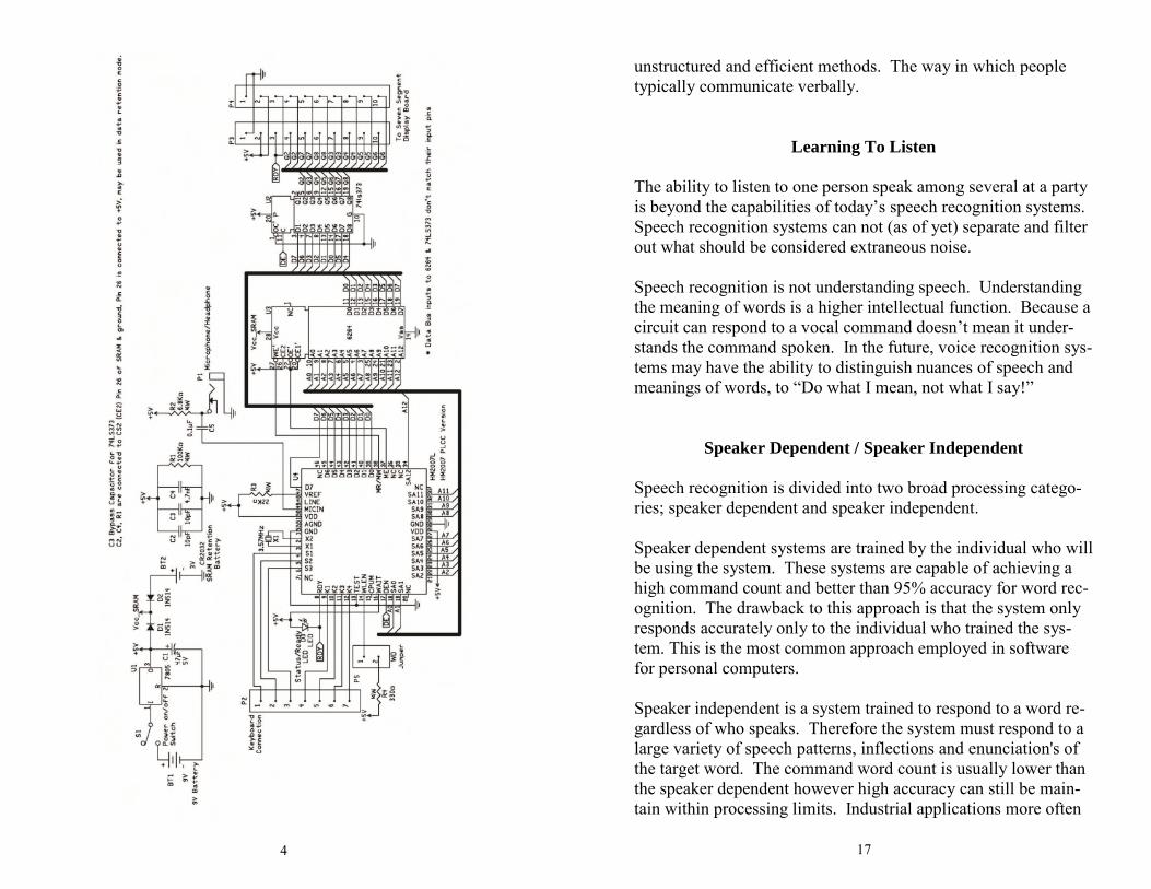
Speaker Dependent / Speaker Independent
Speech recognition is divided into two broad processing catego-ries; speaker dependent and speaker independent.
Speaker dependent systems are trained by the individual who willbe using the system. These systems are capable of achieving ahigh command count and better than 95% accuracy for word rec-ognition. The drawback to this approach is that the system onlyresponds accurately only to the individual who trained the sys-tem. This is the most common approach employed in softwarefor personal computers.
Speaker independent is a system trained to respond to a word re-gardless of who speaks. Therefore the system must respond to alarge variety of speech patterns, inflections and enunciation's ofthe target word. The command word count is usually lower thanthe speaker dependent however high accuracy can still be main-tain within processing limits. Industrial applications more often
16
Figure 5
5
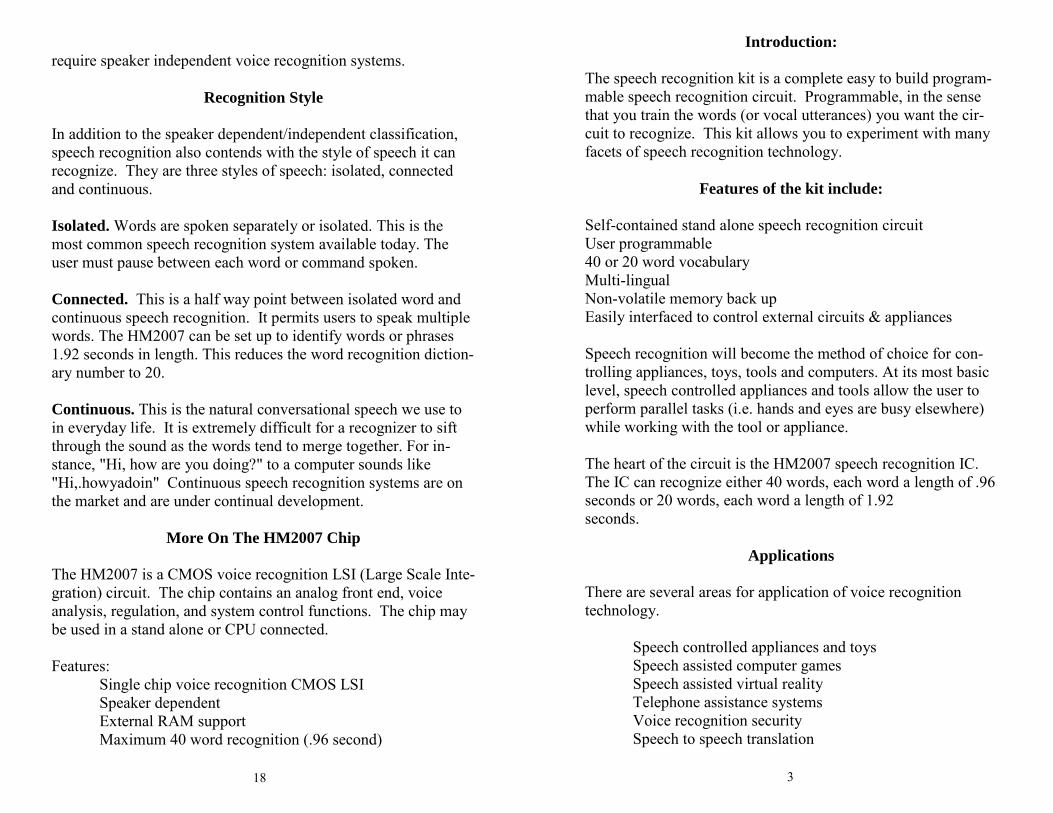
Circuit Construction
The schematic for the SR-07 Speech Recognition Circuit isshown in figure 1. The SR-07 utilizes three separate printedcircuit boards (pcb). The components are mounted on the topside of each pc board. The top sides of the boards have whitesilk screen component drawings. The components are soldered
on the opposite side ofthe pc board. After sol-dering the component tothe board any excesswire is clipped off.
Chip Installation
When installing inte-grated circuit (IC)chips, begin by firstidentifying the top ofthe chip. The top of thechip has a marker,many times it is a halfcircle cutout. Some-
times it is a small mark identifying pin 1 on the IC. In bothcases the marks show us the top ofthe IC chip. Orientated the topof IC chips with the white silkscreen drawings of the compo-nents on the top of the pc board(usually a half circle cutout) oron the parts placement drawingsand install the IC into theirsocket.
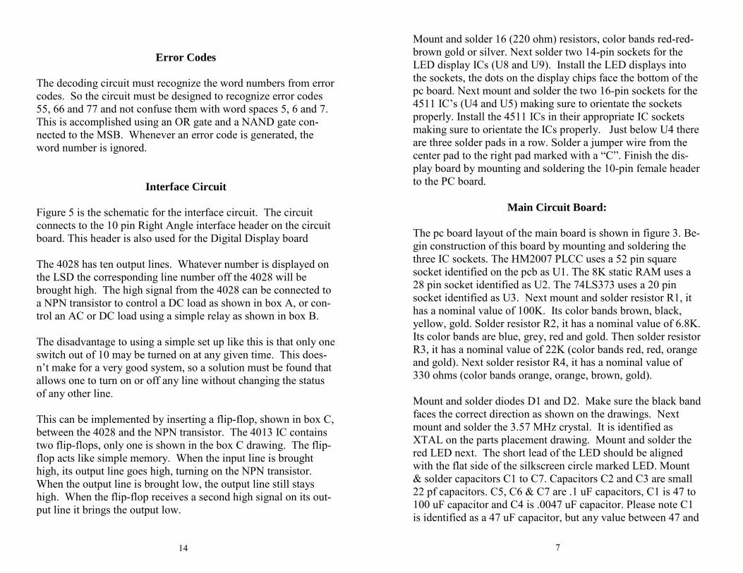
Display Board:
We start construction with thedisplay board, see figure 2.
Figure 2
Finished Display Board

6
Figure 3
15
OK, lets see how this works in the real world. Lets assume youhave the power to a printer connected through the speech recog-nition circuit and a 4013 controlled switch or relay. The targetword is “printer”. When you want to turn the printer on you usethe command word “printer”. The circuit recognizes the wordand applies power to the printer. At this point you can also turnon (or off) any other circuit connected to the speech board, be-cause when the high signal goes low the 4013 keeps its outputhigh. When you are ready to turn off the power to the printer allyou have to do is repeat the command “printer”. The second timethe line is brought high, the output of the 4013 is brought low.
The same command is used to turn the unit on and off. Any ofthe other lines can be turned on or off without affecting the statusof the other output lines.
Voice Security System
This circuit isn’t designed for a voice security system in a com-mercial application, but that should not prevent anyone from ex-perimenting with it for that purpose. A common approach is touse three or four keywords that must be spoken and recognized insequence in order to open a lock or allow entry.
CPU Mode
The HM2007 speech recognition chip has a CPU mode to be usedwhen connected to a host computer system or microcontroller. Tointerface the HM2007 to a host computer requires the writing ofdriver software as well as designing and building the hardwareinterface to the computer data buss.
Aural Interfaces
It’s been found that mixing visual and aural information is noteffective. Products that require visual confirmation of an auralcommand grossly reduces efficiency. To create an effective AUIproducts need to understand (recognize) commands given in an
14
Error Codes
The decoding circuit must recognize the word numbers from errorcodes. So the circuit must be designed to recognize error codes55, 66 and 77 and not confuse them with word spaces 5, 6 and 7.This is accomplished using an OR gate and a NAND gate con-nected to the MSB. Whenever an error code is generated, theword number is ignored.
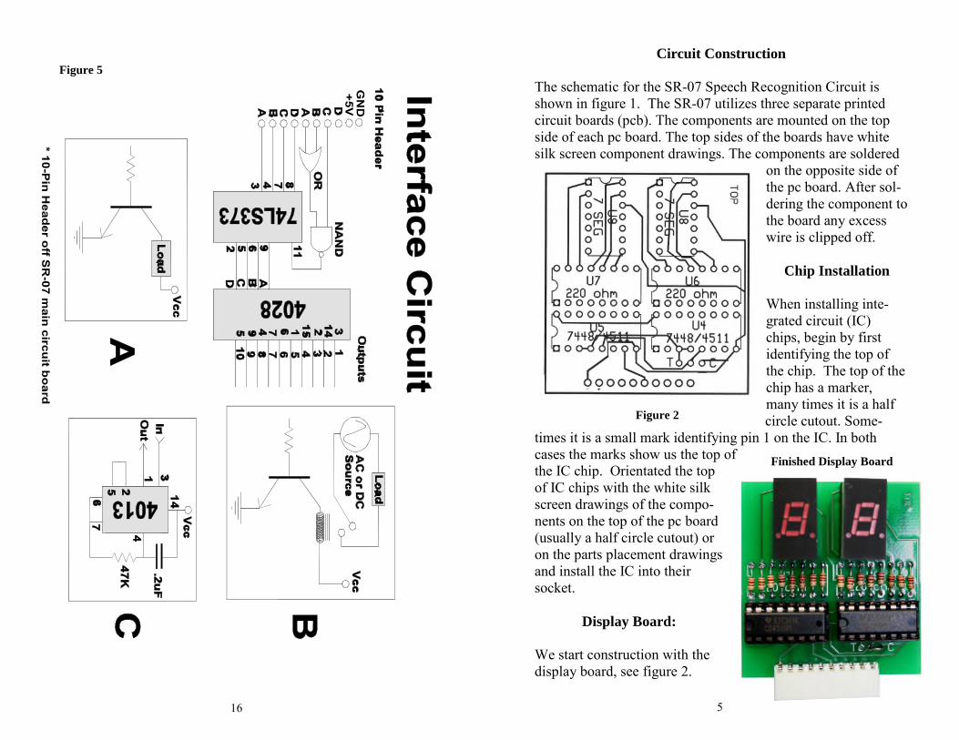
Interface Circuit
Figure 5 is the schematic for the interface circuit. The circuitconnects to the 10 pin Right Angle interface header on the circuitboard. This header is also used for the Digital Display board
The 4028 has ten output lines. Whatever number is displayed onthe LSD the corresponding line number off the 4028 will bebrought high. The high signal from the 4028 can be connected toa NPN transistor to control a DC load as shown in box A, or con-trol an AC or DC load using a simple relay as shown in box B.
The disadvantage to using a simple set up like this is that only oneswitch out of 10 may be turned on at any given time. This does-n’t make for a very good system, so a solution must be found thatallows one to turn on or off any line without changing the statusof any other line.
This can be implemented by inserting a flip-flop, shown in box C,between the 4028 and the NPN transistor. The 4013 IC containstwo flip-flops, only one is shown in the box C drawing. The flip-flop acts like simple memory. When the input line is broughthigh, its output line goes high, turning on the NPN transistor.When the output line is brought low, the output line still stayshigh. When the flip-flop receives a second high signal on its out-put line it brings the output low.
7
Mount and solder 16 (220 ohm) resistors, color bands red-red-brown gold or silver. Next solder two 14-pin sockets for theLED display ICs (U8 and U9). Install the LED displays intothe sockets, the dots on the display chips face the bottom of thepc board. Next mount and solder the two 16-pin sockets for the4511 IC’s (U4 and U5) making sure to orientate the socketsproperly. Install the 4511 ICs in their appropriate IC socketsmaking sure to orientate the ICs properly. Just below U4 thereare three solder pads in a row. Solder a jumper wire from thecenter pad to the right pad marked with a “C”. Finish the dis-play board by mounting and soldering the 10-pin female headerto the PC board.
Main Circuit Board:
The pc board layout of the main board is shown in figure 3. Be-gin construction of this board by mounting and soldering thethree IC sockets. The HM2007 PLCC uses a 52 pin squaresocket identified on the pcb as U1. The 8K static RAM uses a28 pin socket identified as U2. The 74LS373 uses a 20 pinsocket identified as U3. Next mount and solder resistor R1, ithas a nominal value of 100K. Its color bands brown, black,yellow, gold. Solder resistor R2, it has a nominal value of 6.8K.Its color bands are blue, grey, red and gold. Then solder resistorR3, it has a nominal value of 22K (color bands red, red, orangeand gold). Next solder resistor R4, it has a nominal value of330 ohms (color bands orange, orange, brown, gold).
Mount and solder diodes D1 and D2. Make sure the black bandfaces the correct direction as shown on the drawings. Nextmount and solder the 3.57 MHz crystal. It is identified asXTAL on the parts placement drawing. Mount and solder thered LED next. The short lead of the LED should be alignedwith the flat side of the silkscreen circle marked LED. Mount& solder capacitors C1 to C7. Capacitors C2 and C3 are small22 pf capacitors. C5, C6 & C7 are .1 uF capacitors, C1 is 47 to100 uF capacitor and C4 is .0047 uF capacitor. Please note C1is identified as a 47 uF capacitor, but any value between 47 and

8
100 uF may be substituted in the kit.Mount & solder the 7805 voltage regulator and on-off slideswitch. Next mount and solder the microphone jack and buttonbattery holder and 9-volt battery cap. Keep the wires on the 9-volt battery cap short, about 1.5” long.Mount and solder the 10-pin right angle header in the upper lefthand corner of the board identified as R1. Mount and solder the 7-pin right angle header in the lower left corner of the board,Mount and solder a 2-pin header in the WD location next to R4.Install the integrated circuits in their appropriate IC sockets mak-ing sure to orientate the IC’s properly.
Keypad:
The keypad is constructed using 12 normally open momentarycontact switches. Place each switch in its mounting position andbend the leads inward to secure the switch to the PCB for solder-ing. After mounting and soldering the 12 keypad switches to the
SR-07 Main Circuit Board
13
Rhyming words
Rhyming words are words that sound alike. For instance thewords cat, bat, sat and fat sound alike. Because of their likesounding nature they can confuse the speech recognition circuit.When choosing target words for your system do not use rhymingwords.
The Voice With Stress & Excitement
Stress and excitement alters ones voice. This affects the accuracyof the circuit’s recognition. For instance assume you are sittingat your workbench and you program the target words like fire,left, right, forward, etc., into the circuit. Then you use the circuitto control a flight simulator game, Doom or Duke Nukem. Well,when you’re playing the game you’ll likely be yelling “FIRE!…Fire!...FIRE!!...LEFT…go RIGHT!”. In the heat of the actionyou’re voice will sound much different than when you were sit-ting down relaxed and programming the circuit. To achieve ahigher accuracy word recognition one needs to mimic the excite-ment in ones voice when programming the circuit.
These factors should be kept in mind to achieve the high accu-racy possible from the circuit. This becomes increasingly impor-tant when the speech recognition circuit is taken out of the laband put to work in the outside world.
Interfacing The Circuit To The Outside World
The circuit design for interfacing the speech recognition systemto the outside world controls ten switches. This design idea fitswith the robust speech recognition system discussed previously.While the effective vocabulary drops from forty to ten words, wegain in a more robust and accurate system.

12
Simulated Independent Recognition
The speech recognition system is speaker dependant, meaning thatthe voice that trained the system has the highest recognition accu-racy. But you can simulate independent speech recognition.
To make the recognition system simulate speaker independenceone uses more than one word space for each target word. Set theSR-07 for a 40 word vocabulary. Now we use four word spacesper target word. Therefore we obtain four different enunciation’sof each target word. (speaker independent)
The four word spaces are chosen to minimize software and hard-ware interfaces into the circuit. To accomplish this the four wordspaces are chosen so that they all have the same Least SignificantDigit (LSD). Doing this the words can be recognized by just de-coding the least significant digit (number) on the digital display.
Using this procedure the word spaces 01, 11, 21 and 31 are allo-cated to the first target word. The Most Significant Digit (MSD)is dropped by the interfacing circuits. By only decoding only theLSD number, in this case 1 of “X1” (where X is any number) wecan recognize the target word.
We continue do this for the remaining word space. For instance,the second target word will use the word spaces 02, 12, 22 and 32.We continue in this manner until all the words are programmed.
If you are experimenting with speaker independence use differentpeople when training a target word. This will enable the system torecognize different voices, inflections and enunciation's of the tar-get word. The more system resources that are allocated for inde-pendent recognition the more robust the circuit will become.
If you are experimenting with designing the most robust and accu-rate system possible, train target words using one voice with dif-ferent inflections and enunciation's of the target word.
9
top of the keypad PCB, connect the7-pin female header to the bottomof the keypad pcb.
Non-Volatile Memory Back-up
The PC mounted coin batteryholder holds a 2032 coin battery,which supplies backup for theSRAM. This allows the word pat-terns to be retained in memorywhen the main circuit is turned off.
Selecting Vocabulary Size andWord Length
The default vocabulary and wordconfiguration for the circuit is 40words, each with a length of .96seconds. If you wish to change this
to 20 word with a length of 1.92 seconds place a jumper on thetwo-pin WD header.If you do not need the 40 wordvocabulary, it is suggested youconfigure the circuit for the 20word vocabulary as this configura-tion usually provides a better rec-ognition accuracy.
Using The Speech RecognitionCircuit
The keypad and digital display areused to communicate with andprogram the HM2007 chip. Plugthe digital display into the 10-pinheader on the main circuit board.Plug the keypad into the 7-pin
Figure 4
Keypad

10
header on the main circuit board. Plug the headset microphoneinto the microphone jack. Adjust the microphone so that it is po-sition about 1” away from your mouth.
Keypad Use:The keypad is made up of 12 normally open momentary contactswitches.
1 2 3
4 5 6
7 8 9
CLR 0 TRNClear Train
The CLR key equals Clear and theTRN key equal Train.
When the circuit is turned on, “00” is on the digital display, thered LED (READY) is lit and the circuit waits for a command.
Training Words for Recognition
To Train:
Press “1” (display will show “01” and the LED will turn off) onthe keypad, then press the TRN key ( the LED will turn on) toplace circuit in training mode, for word one.
Say the target word into the headset microphone clearly. Thecircuit signals acceptance of the voice input by blinking the LEDoff then on. The word (or utterance) is now identified as the“01” word. If the LED did not flash, start over by pressing “1”and then “TRN” key.
Finished SR-07 Circuit
11
You may continue training new words in the circuit. Press “2”then TRN to train the second word and so on. The circuit willaccept and recognize up to 40 words (numbers 1 through 40). Itis not necessary to train all word spaces. If you only require 10target words that’s all you need to train.
Testing Recognition:
Repeat a trained word into the microphone. The number of theword should be displayed on the digital display. For instance, ifthe word “directory” was trained as word number 25, saying theword “directory” into the microphone will cause the number 25to be displayed.
Error Codes:
The chip provides the following error codes.
55 = word to long66 = word to short77 = no match
Clearing Memory
To erase all words in memory press “99” and then “CLR”. Thenumbers displayed are “19”, this is not an error. The numberswill quickly scroll by on the digital display as the memory iserased.
Changing & Erasing Words
Trained words can easily be changed by overwriting the originalword. For instances suppose word six was the word “Capital”and you want to change it to the word “State”. Simply retrainthe word space by pressing “6” then the TRN key and saying theword “State” into the microphone.If one wishes to erase the word without replacing it with anotherword press the word number (in this case six) then press theCLR key. Word six is now erased.