Embed Size (px)
Citation preview
ASSEMBLY ll OPERATION ll MAINTENANCE908 $4.00 50056690
SSqquueeaalleerr SSeerriieess RRoottaarryy CCuutttteerrssSSQQ114422,, SSQQ114488,, SSQQ116600,, SSQQ117722,, SSQQ118844,, SSQQ8844TT OOppeerraattoorr’’ss MMaannuuaall
BUSH HOG®

CONGRATULATIONS!You have invested in the best implement of its type on the market today.
The care you give your Bush Hog implement will greatly determine your satisfactionwith its performance and its service life. We urge a careful study of this manual to provideyou with a thorough understanding of your new implement before operating, as well assuggestions for operation and maintenance.
If your manual should become lost or destroyed, Bush Hog will be glad to provide you witha new copy. Order from Bush Hog, P. O. Box 1039, Selma, Alabama 36702-1039. Most of ourmanuals can also be downloaded from our website at www.bushhog.com.
As an authorized Bush Hog dealer, we stock genuine Bush Hog parts which aremanufactured with the same precision and skill as our original equipment. Our trainedservice personnel are well informed on methods required to service Bush Hog equipment,and are ready and able to help you.
Should you require additional information or assistance, please contact us.
YOUR AUTHORIZEDBUSH HOG DEALER
BECAUSE BUSH HOG MAINTAINS AN ONGOINGPROGRAM OF PRODUCT IMPROVEMENT, WE RESERVE THE RIGHT TO MAKE IMPROVEMENTS IN DESIGN OR CHANGES IN SPECIFICATIONS WITH-OUT INCURRING ANY OBLIGATION TO INSTALL THEM ON UNITS PREVIOUSLY SOLD.
BECAUSE OF THE POSSIBILITY THAT SOMEPHOTOGRAPHS IN THIS MANUAL WERE TAKEN OF PROTOTYPE MODELS, PRODUCTION MODELS MAY VARY IN SOME DETAIL. IN ADDITION, SOMEPHOTOGRAPHS MAY SHOW SHIELDS REMOVED FOR PURPOSES OF CLARITY. NEVER OPERATETHIS IMPLEMENT WITHOUT ALL SHIELDS IN PLACE.

SQUEALER ROTARY CUTTERSTABLE OF CONTENTS
SECTION/PARA PAGEWarranty.................................................2Dealer Preparation Check List ...............3Safety Precautions.................................4Federal Laws and Regulations ..............5
I. INTRODUCTION & DESCRIPTION ......61-1 Introduction ......................................6
II. PREPARATION FOR USE.....................72-1 Attaching To Tractor ........................7
III.OPERATING INSTRUCTIONS ..............93-1 General Safety.................................93-2 Adjusting for Work ...........................93-2.1 Cutting Height Adjustment ............93-3 Operation .........................................9
IV.MAINTENANCE...................................104-1 Maintenance Check List ................104-2 Lubrication .....................................104-3 Blade Replacement .......................114-4 Shear Bolt Replacement................124-5 Shear Bolt Replacement................124-6 Slip Clutch Operational Check.......124-7 Slip Clutch Adjustment...................12
SECTION/PARA PAGE4-8 Blade Holder And Gearbox
Removal (All Except SQ84T)........124-9 Blade Holder AndGearbox
Installation (All Except SQ84T) .....134-10 Blade Holder And Gearbox
Removal (SQ84T Only)...............134-11 Blade Holder And Gearbox
Assembly (SQ84T Only) .............134-12 Troubleshooting ..........................13
V. ASSEMBLY .........................................155-1 Assembly ......................................155-2 Optional Front Shielding Installation
(SQ 420, 480, 600, 720 & 840) ....165-3 Optional Front Shielding Installation
(SQ84T) .......................................165-4 Optional Rear Band Installation
(SQ420, 480, 600, 720 & 840) ......165-5 Front and Rear Chain Installation .165-6 Rear Band Installation (SQ84T)...175-7 Gearbox Input Shield (SQ84T) ....17Safety Decals ......................................18Torque Specifications ..........................19
RETAIL CUSTOMER’S RESPONSIBILITYUNDER THE BUSH HOG WARRANTY
It is the Retail Customer and/or Operator’s responsibility to read the Operator’s Manual, tooperate, lubricate, maintain and store the product in accordance with all instructions andsafety procedures. Failure of the operator to read the Operator’s Manual is a misuse of thisequipment.
It is the Retail Customer and/or Operator’s responsibility to inspect the product and to haveany part(s) repaired or replaced when continued operation would cause damage or exces-sive wear to other parts or cause a safety hazard.
It is the Retail Customer’s responsibility to deliver the product to the authorized Bush HogDealer, from whom he purchased it, for service or replacement of defective parts which arecovered by warranty. Repairs to be submitted for warranty consideration must be made with-in forty-five (45) days of failure.
It is the Retail Customer’s responsibility for any cost incurred by the Dealer for traveling to orhauling of the product for the purpose of performing a warranty obligation or inspection.
1

LIMITED WARRANTY✯✯✯✯✯✯✯✯✯✯✯✯✯✯✯✯✯✯✯✯✯✯✯✯✯✯✯✯✯✯✯
Bush Hog warrants to the original purchaser of any new Bush Hog equipment, purchased from anauthorized Bush Hog dealer, that the equipment be free from defects in material and workmanship for a periodof one (1) year for non-commercial, state, and municipalities’ use and ninety (90) days for commercial use fromdate of retail sale. Squealer Model gearboxes (With the exception of Model 84T) are covered by a five (5) yearlimited warranty period. The obligation of Bush Hog to the purchaser under this warranty is limited to the repairor replacement of defective parts.
Replacement or repair parts installed in the equipment covered by this limited warranty are warrantedfor ninety (90) days from the date of purchase of such part or to the expiration of the applicable new equip-ment warranty period, whichever occurs later. Warranted parts shall be provided at no cost to the user at anauthorized Bush Hog dealer during regular working hours. Bush Hog reserves the right to inspect any equip-ment or parts which are claimed to have been defective in material or workmanship.
DISCLAIMER OF IMPLIED WARRANTIES & CONSEQUENTIAL DAMAGES
Bush Hog’s obligation under this limited warranty, to the extent allowed by law, is in lieu of all war-ranties, implied or expressed, INCLUDING IMPLIED WARRANTIES OF MERCHANTABILITY AND FITNESSFOR A PARTICULAR PURPOSE and any liability for incidental and consequential damages with respect tothe sale or use of the items warranted. Such incidental and consequential damages shall include but not belimited to: transportation charges other than normal freight charges; cost of installation other than costapproved by Bush Hog; duty; taxes; charges for normal service or adjustment; loss of crops or any other loss ofincome; rental of substitute equipment, expenses due to loss, damage, detention or delay in the delivery ofequipment or parts resulting from acts beyond the control of Bush Hog.
THIS LIMITED WARRANTY SHALL NOT APPLY:
1. To vendor items which carry their own warranties, such as engines, tires, and tubes.
2. If the unit has been subjected to misapplication, abuse, misuse, negligence, fire or other accident.
3. If parts not made or supplied by Bush Hog have been used in connection with the unit, if, in the sole judge-ment of Bush Hog such use affects its performance, stability or reliability.
4. If the unit has been altered or repaired outside of an authorized Bush Hog dealership in a mannerwhich, in the sole judgement of Bush Hog, affects its performance, stability or reliability.
5. To normal maintenance service and normal replacement items such as gearbox lubricant, hydraulic fluid, worn blades, or to normal deterioration of such things as belts and exterior finish due to use or exposure.
6. To expendable or wear items such as teeth, chains, sprockets, belts, springs and any other items that in thecompany’s sole judgement is a wear item.
NO EMPLOYEE OR REPRESENTATIVE OF BUSH HOG IS AUTHORIZED TO CHANGE THIS LIM-ITED WARRANTY IN ANY WAY OR GRANT ANY OTHER WARRANTY UNLESS SUCH CHANGE IS MADE IN WRITING AND SIGNED BY BUSH HOG’S SERVICE MANAGER, POST OFFICE BOX 1039, SELMA,ALABAMA 36702-1039.
✯✯✯✯✯✯✯✯✯✯✯✯✯✯✯✯✯✯✯✯✯✯✯✯✯✯✯✯✯✯✯Record the model number, serial number and datepurchased. This information will be helpful to yourdealer if parts or service are required.MAKE CERTAIN THE WARRANTY REGISTRATION CARD HAS BEEN FILED WITH BUSH HOG/SELMA, ALABAMA
MODEL NUMBER
SERIAL NUMBER
DATE OF RETAIL SALE
2

DEALER PREPARATION CHECK LIST
SQUEALER ROTARY CUTTERS
BEFORE DELIVERING MACHINE — The following check list should be completed.Use the Operator’s Manual as a guide.
❒ 1. Assembled completed.
❒ 2. Gearbox filled with oil.
❒ 3. All fittings lubricated.
❒ 4. All shields in place and in good condition.
❒ 5. All fasteners torqued to specifications given in Torque Chart.
❒ 6. Slip clutches have been checked for proper operation.
❒ 7. All decals in place and readable. (See decal page.)
❒ 8. Overall condition good (i.e. paint, welds)
❒ 9. Operators manual has been delivered to owner and he has been instructedon the safe and proper use of the cutter.
❒ 10. Purchaser or dealer elects to delete deflectors. (front belting, rear bands,front and rear chains)
Explanation:
Dealer’sSignature
Purchaser’sSignature
THIS CHECKLIST TO REMAIN IN OWNER’S MANUALIt is the responsibility of the dealer to complete the procedures listed
above before delivery of this implement to the customer.
WARNINGFor Non-Agricultural use, OSHA, ASAE, SAE and ANSI standards require the use ofChain Guards or other protective guards at all times. Bush Hog strongly recommendsthe use of such guards for Agricultural uses as well, to reduce the risk of propertydamage, serious bodily injury or even death from objects thrown out by or from con-tact with the cutting blades.
3

IMPORTANT SAFETY PRECAUTIONSThis symbol is used to call attention to safe-ty precautions that should be followed by the operator to avoid accidents. When you see this symbol, carefully read the message that follows and heed its advice. Failure to comply with safety precautions could result in serious bodily injury.
In addition to the design and configuration of equipment, hazard control and accident prevention are depen-dent upon the awareness, concern, prudence and proper training of personnel in the operation, transport, maintenance and storage of equipment. Lack of attention to safety can result in accident, personal injury, reduction of efficiency and worst of all—loss of life. Watch for safety hazards and correct deficiencies prompt-ly. Use the following safety precautions as a general guide to safe operations when using this machine. Additional safety precautions are used throughout this manual for specific operating and maintenance proce-dures. Read this manual and review the safety precautions often until you know the limitations.
1. Read the Operator’s Manual. Failure to read the Operator’s Manual is considered a misuse of this equipment.
2. Become familiar with all the machine’s controls and all the caution, warning and danger decals affixedto the machine before attempting to start or operate.
3. Before starting or operating the machine, make a walk around inspection and check for obvious defects such as loose mounting bolts and damaged components. Correct any deficiency beforestarting.
4. Do not allow children to operate the cutter. Do not allow adults to operate it without proper instruction.
5. Do not carry passengers.
6. Keep the area of operation clear of all persons, particularly small children and pets. The operator should cease mowing whenever anyone comes within the operating area.
7. Clear the work area of objects which might be picked up and thrown.
8. Use a piece of cardboard or wood rather than hands to search for hydraulic leaks. Escaping hydraulic oil under pressure can penetrate skin. If fluid is injected into the skin, it must be surgically removed within a few hours by a doctor familiar with this form of injury or gangrene may result.
9. Do not operate without all guards and shields in place and in good condition.
10. Lower implement to ground, stop tractor engine, apply parking brake, and allow blades to completely stop before leaving the tractor.
11. Keep hands and feet away from blades.
12. This cutter is not to be operated along highways or in any area where people may be present unless all sides of the unit are enclosed by permanent bands, safety chains or other factory approved safety shields that are in good repair.
13. Wear personal protective equipment such as, but not limited to, protection for eyes, ears, feet, hands and head when operating or repairing the equipment. Do not wear loose clothing or jewelry that may catch on equipment moving parts.
14. When performing adjustments or maintenance on the cutter, first lower it to the ground or block it securely at a workable height.
15. Never stand between tractor and cutter while tractor is being backed to the cutter hitch.
16. Reduce speed when transporting cutter to avoid bouncing and momentary loss of steering.
17. Use tractor flashing warning lights, day or night, when transporting cutter on road or highways unless prohibited by law.
18. In the event that someone other than yourself will operate this equipment we firmly suggest that all SAFETY references be discussed prior to operation.
19. Use ROPS (Rollover Protective Structures) and seat belt equipped tractors for mowing operations.
4
IMPORTANT FEDERAL LAWS AND REGULATIONS* CONCERNINGEMPLOYERS, EMPLOYEES AND OPERATIONS.
*(This section is intended to explain in broad terms the concept and effect of the following federal laws andregulations. It is not intended as a legal interpretation of the laws and should not be considered as such).
U.S. Public Law 91-596 (The Williams-Steiger Occupational and Health Act of 1970) OSHA
This Act Seeks:“...to assure so far as possible every working man and woman in the nation safe and healthful workingconditions and to preserve our human resources...”
DUTIESSec. 5 (a) Each employer—(1) shall furnish to each of his employees employment and a place of employment
which are free from recognized hazards that are causing or are likely to causedeath or serious physical harm to his employees;
(2) shall comply with occupational safety and health standards promulgated underthis Act.
(b) Each employee shall comply with occupational safety and health standardsand all rules, regulations and orders issued pursuant to this Act which areapplicable to his own actions and conduct.
OSHA RegulationsCurrent OSHA regulations state in part: “At the time of initial assignment and at least annually thereafter, theemployer shall instruct every employee in the safe operation and servicing of all equipment with which theemployee is, or will be involved.” These will include (but are not limited to) instructions to:
Keep all guards in place when the machine is in operation;
Permit no riders on equipment;
Stop engine, disconnect the power source, and wait for all machine movement to stop before servicing, adjusting, cleaning or unclogging the equipment, except where the machine must berunning to be properly serviced or maintained, in which case the employer shall instruct employeesas to all steps and procedures which are necessary to safely service or maintain the equipment.
Make sure everyone is clear of machinery before starting the engine, engaging power, or operating the machine.
Child Labor Under 16 Years OldSome regulations specify that no one under the age of 16 may operate power machinery. It is yourresponsibility to know what these regulations are in your own area or situation. (Refer to U.S. Dept. ofLabor, Employment Standard Administration, Wage & Home Division, Child Labor Bulletin #102.)
EMPLOYEE TRACTOR OPERATING INSTRUCTIONS:1. Securely fasten your seat belt if the tractor has a
ROPS.
2. Where possible, avoid operating the tractor near ditches, embankments, and holes.
3. Reduce speed when turning, crossing slopes, andon rough, slick, or muddy surfaces.
4. Stay off slopes too steep for safe operation.
5. Watch where you are going, especially at row ends, on roads, and around trees.
6. Do not permit others to ride.
7. Operate the tractor smoothly - no jerky turns, starts, or stops.
8. Hitch only to the drawbar and hitch points recom-mended by tractor manufacturers.
9. When tractor is stopped, set brakes securely and use park lock if available.
5

SECTION IINTRODUCTION AND DESCRIPTION
1-1 INTRODUCTIONWe are pleased to have you as a Bush Hog cus-tomer. Your Squealer Series Rotary Cutter has beencarefully designed to give maximum service withminimum down time. This manual is provided to giveyou the necessary operating and maintenanceinstructions for keeping your rotary cutter in topoperating condition. Please read this manual thor-oughly. Understand what each control is for and howto use it. Observe all safety precautions decaled onthe machine and noted throughout the manual forsafe operation of implement. If any assistance oradditional information is needed, contact your autho-rized Bush Hog dealer.
TABLE 1-1 TECHNICAL SPECIFICATIONSModel No. SQ142 SQ148 SQ160 SQ172 SQ84T SQ184
Length 79” 85” 97” 109.5” 75” 125.5”
Width 46-1/2” 52-1/2” 64-1/2” 76-1/2” 87” 88-1/2”
Cutting Width 42” 48” 60” 72” 84” 84”
Weight (Est.) 402 lbs. 472 lbs. 651 lbs. 774 lbs. 720 lbs. 1024 lbs.
CuttingCapacity 1-1/2” dia 1-1/2” dia. 1-1/2” dia. 1-1/2” dia. 1” dia. 1-1/2” dia.
Cutting 2” - 12” 2” - 12” 2” - 12” 2” - 12” 2” - 12” 1” - 10”Height
Type Hitch Cat.0&1&QH Cat. 1&QH Cat. 1&QH Cat. 1&QH Cat. 1 Cat. 2&QHGearbox HP 45 45 65 65 Main 60 90
Outboard 45
Blade Tip 12,861 13,029 14,335 14,963 11,500 14,963Speed ft./min. ft./min. ft./min. ft./min. ft./min. ft./min.
Blades 3/8 x 3” 3/8 x 3” 1/2 x 4” 1/2 x 4” 1/2 x 4” 1/2 x 4”
Shear Bolt Size 1/2 x 3” 1/2 x 3” 8 x 50mm, Gr.8.8 8 x 50mm, Gr.8.8 Slip Clutch Slip ClutchGr. 2 Gr. 2 Slip Clutch Slip Clutch
Optional OptionalRecommendedTractor HP 10 - 25 15 - 25 25 - 40 30 - 45 25 - 50 50 Min.
6
The squealer Cutters (Figure 1-1) are light duty cut-ters designed for cutting grass and small brush.Each cutter has free-swinging blades which reducethe shock of impact when a stationary object is hit. Ashear bolt through the input shaft (SQ142, SQ148)or offset shear bolt (SQ160, SQ172) protects thegearbox and driveline from damage on all modelsexcept the SQ184 and SQ84T, which have slipclutches standard. Slip clutches are optional forModels SQ160 and SQ172. Standard equipmentincludes driveline shields, clutch shields and frontand rear discharge shields(deflectors). NOTE:Dealer or purchaser may elect to delete front andrear discharge shields (deflectors) at their option.Refer to “WARNINGS” in Section 3-3.
Figure 1-1 Major Components
A-Frame
Driveline
Tailwheel
Cutter Deck
7
NOTEDue to the many variations in tractor / imple-ment hitch points and corresponding differ-ences in distances between tractor PTOshafts and implement input shafts, drivelinesmay need to be shortened as described in thefollowing steps:
SECTION IIPREPARATION FOR USE
2-1 ATTACHING TO TRACTOR
NEVER STAND BETWEEN TRACTOR AND CUTTER WHILE TRACTOR IS BEING BACKED TO HITCH.
ADDITIONAL TRACTOR FRONT BALLAST MAY BE NEEDED FOR STABLE OPERATION AND TRANSPORT OF THE 3-POINT HITCHMOUNTED CUTTER. SEE TRACTOR OPERA-TOR’S MANUAL FOR RECOMMENDEDWEIGHTS.
DO NOT USE PTO SHAFT ADAPTERS TO CHANGE SIZE OF TRACTOR PTO SHAFT. THE CORRECT DRIVELINE MUST BE USED TO MATCH TRACTOR PTO SHAFT.
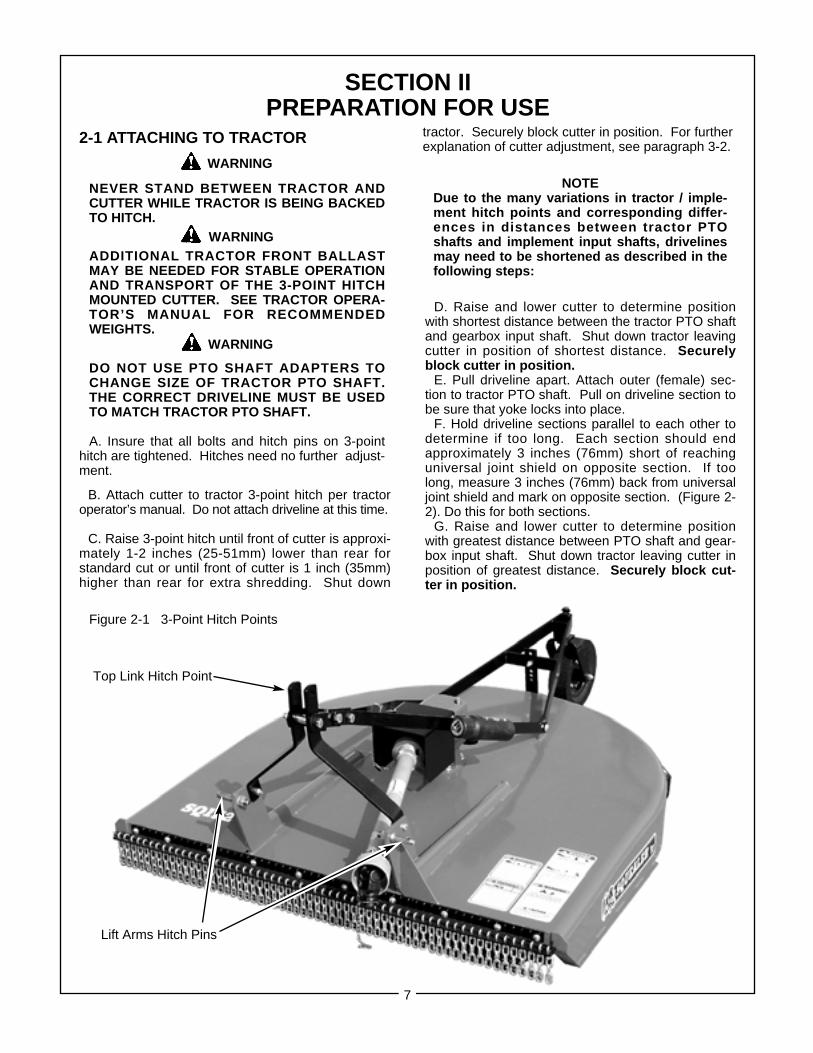
A. Insure that all bolts and hitch pins on 3-pointhitch are tightened. Hitches need no further adjust-ment.
B. Attach cutter to tractor 3-point hitch per tractoroperator’s manual. Do not attach driveline at this time.
C. Raise 3-point hitch until front of cutter is approxi-mately 1-2 inches (25-51mm) lower than rear forstandard cut or until front of cutter is 1 inch (35mm)higher than rear for extra shredding. Shut down
WARNING
WARNING
WARNING
D. Raise and lower cutter to determine positionwith shortest distance between the tractor PTO shaftand gearbox input shaft. Shut down tractor leavingcutter in position of shortest distance. Securelyblock cutter in position.
E. Pull driveline apart. Attach outer (female) sec-tion to tractor PTO shaft. Pull on driveline section tobe sure that yoke locks into place.
F. Hold driveline sections parallel to each other todetermine if too long. Each section should endapproximately 3 inches (76mm) short of reachinguniversal joint shield on opposite section. If toolong, measure 3 inches (76mm) back from universaljoint shield and mark on opposite section. (Figure 2-2). Do this for both sections.
G. Raise and lower cutter to determine positionwith greatest distance between PTO shaft and gear-box input shaft. Shut down tractor leaving cutter inposition of greatest distance. Securely block cut-ter in position.
tractor. Securely block cutter in position. For furtherexplanation of cutter adjustment, see paragraph 3-2.
Figure 2-1 3-Point Hitch Points
Top Link Hitch Point
Lift Arms Hitch Pins

8
Figure 2-2
H. Hold driveline sections parallel to each otherand check for minimum 6 inches (15cm) overlap.Figure 2-3). If driveline has been marked for cutting,overlap will be the distance between two marks. Ifdriveline has less than minimum overlap, do not use.Contact authorized Bush Hog dealer.
NOTEIf driveline is the correct length, omit the followingsteps “I” through “L” and proceed to step “M”.
I. Clamp driveline in a well padded vice to pre-vent damage to the shield. Cut off shield wheremarked. (Figure 2-4)
Figure 2-3Minimum Overlap
Figure 2-4
J. Using cut off section of shield as a guide, cutshaft the same amount. (Figure 2-5)
Figure 2-5
K. Repeat steps “I” and “J” to other drivelinesection.
L. Deburr ends of driveline sections and cleanaway all chips and filings. (Figure 2-6)
Figure 2-6
M. Apply multi-purpose grease to inside of outer(female) driveline section. Assemble driveline andinstall on tractor and cutter. Pull on each drivelinesection to be sure yokes lock into place. Make certaindriveline shielding is in place and in good condition.
N. Adjust lower lift arm(s) to level cutter right to left.Refer to tractor operator's manual for instructions.
NOTEAfter attaching driveline to tractor, attach drivelineshield chains from both ends of driveline shieldingto stationary locations.
AVOID PLACING HANDS, FEET OR ANYOTHER BODY PARTS BENEATH THE CUTTERWHILE MAKING HEIGHT ADJUSTMENTS.
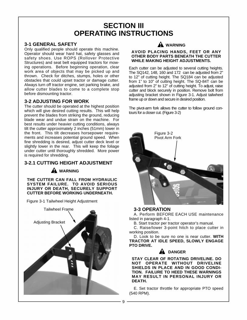
Each cutter can be adjusted to several cutting heights.The SQ142, 148, 160 and 172 can be adjusted from 2”to 12” of cutting height. The SQ184 can be adjustedfrom 1” to 10” of cutting height. The SQ-84T can beadjusted from 2” to 12” of cutting height. To adjust, raisecutter and block securely in position. Remove bolt fromadjusting bracket shown in Figure 3-1. Adjust tailwheelframe up or down and secure in desired position.
The pivot-arm fork allows the cutter to follow ground con-tours for a closer cut. (Figure 3-2)
SECTION IIIOPERATING INSTRUCTIONS
3-1 GENERAL SAFETYOnly qualified people should operate this machine.Operator should wear hard hat, safety glasses andsafety shoes. Use ROPS (Rollover ProtectiveStructures) and seat belt equipped tractors for mow-ing operations. Before beginning operation, clearwork area of objects that may be picked up andthrown. Check for ditches, stumps, holes or otherobstacles that could upset tractor or damage cutter.Always turn off tractor engine, set parking brake, andallow cutter blades to come to a complete stopbefore dismounting tractor.
3-2 ADJUSTING FOR WORKThe cutter should be operated at the highest positionwhich will give desired cutting results. This will helpprevent the blades from striking the ground, reducingblade wear and undue strain on the machine. Forbest results under heavier cutting conditions, alwaystilt the cutter approximately 2 inches (51mm) lower inthe front. This tilt decreases horsepower require-ments and increases potential ground speed. Whenfine shredding is desired, adjust cutter deck level orslightly lower in the rear. This will keep the foliageunder cutter until thoroughly shredded. More poweris required for shredding.
3-2.1 CUTTING HEIGHT ADJUSTMENT
THE CUTTER CAN FALL FROM HYDRAULIC SYSTEM FAILURE. TO AVOID SERIOUSINJURY OR DEATH, SECURELY SUPPORT CUTTER BEFORE WORKING UNDERNEATH.
WARNING
WARNING
3-3 OPERATIONA. Perform BEFORE EACH USE maintenance
listed in paragraph 4-1.B. Start tractor per tractor operator’s manual.C. Raise/lower 3-point hitch to place cutter in
working position.D. Look to be sure no one is near cutter. WITH
TRACTOR AT IDLE SPEED, SLOWLY ENGAGEPTO DRIVE.
STAY CLEAR OF ROTATING DRIVELINE. DONOT OPERATE WITHOUT DRIVELINE SHIELDS IN PLACE AND IN GOOD CONDI-TION. FAILURE TO HEED THESE WARNINGS MAY RESULT IN PERSONAL INJURY OR DEATH.
E. Set tractor throttle for appropriate PTO speed(540 RPM).
DANGER
9
Figure 3-1 Tailwheel Height Adjustment
Tailwheel Frame
Adjusting Bracket
Figure 3-2 Pivot Arm Fork
ROTATING CUTTER BLADES, STAND CLEARUNTIL ALL MOION HAS STOPPED. TO AVOIDAN ACCIDENTAL FALL FROM TRACTORAND POSSIBLE INJURY FROM CUTTER, USEROPS (ROLLOVER PROTECTION STRUC-TURES) AND SEAT BELT EQUIPPED TRAC-TORS FOR ALL MOWING OPERATIONS.
DANGER
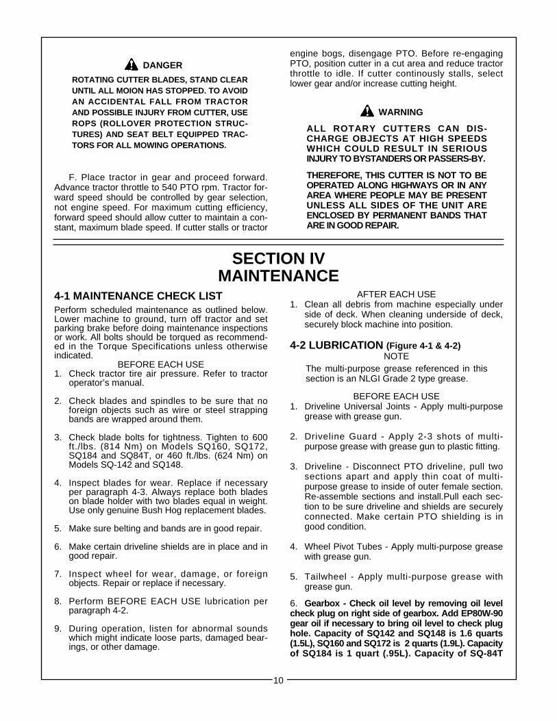
F. Place tractor in gear and proceed forward.Advance tractor throttle to 540 PTO rpm. Tractor for-ward speed should be controlled by gear selection,not engine speed. For maximum cutting efficiency,forward speed should allow cutter to maintain a con-stant, maximum blade speed. If cutter stalls or tractor
ALL ROTARY CUTTERS CAN DIS-CHARGE OBJECTS AT HIGH SPEEDSWHICH COULD RESULT IN SERIOUSINJURY TO BYSTANDERS OR PASSERS-BY.
THEREFORE, THIS CUTTER IS NOT TO BEOPERATED ALONG HIGHWAYS OR IN ANYAREA WHERE PEOPLE MAY BE PRESENTUNLESS ALL SIDES OF THE UNIT AREENCLOSED BY PERMANENT BANDS THATARE IN GOOD REPAIR.
WARNING
engine bogs, disengage PTO. Before re-engagingPTO, position cutter in a cut area and reduce tractorthrottle to idle. If cutter continously stalls, selectlower gear and/or increase cutting height.
SECTION IVMAINTENANCE
4-1 MAINTENANCE CHECK LISTPerform scheduled maintenance as outlined below.Lower machine to ground, turn off tractor and setparking brake before doing maintenance inspectionsor work. All bolts should be torqued as recommend-ed in the Torque Specifications unless otherwiseindicated.
BEFORE EACH USE1. Check tractor tire air pressure. Refer to tractor
operator’s manual.
2. Check blades and spindles to be sure that noforeign objects such as wire or steel strappingbands are wrapped around them.
3. Check blade bolts for tightness. Tighten to 600ft./lbs. (814 Nm) on Models SQ160, SQ172,SQ184 and SQ84T, or 460 ft./lbs. (624 Nm) on Models SQ-142 and SQ148.
4. Inspect blades for wear. Replace if necessary per paragraph 4-3. Always replace both blades on blade holder with two blades equal in weight.Use only genuine Bush Hog replacement blades.
5. Make sure belting and bands are in good repair.
6. Make certain driveline shields are in place and in good repair.
7. Inspect wheel for wear, damage, or foreign objects. Repair or replace if necessary.
8. Perform BEFORE EACH USE lubrication per paragraph 4-2.
9. During operation, listen for abnormal sounds which might indicate loose parts, damaged bear-ings, or other damage.
AFTER EACH USE1. Clean all debris from machine especially under
side of deck. When cleaning underside of deck, securely block machine into position.
4-2 LUBRICATION (Figure 4-1 & 4-2)NOTE
BEFORE EACH USE1. Driveline Universal Joints - Apply multi-purpose
grease with grease gun.
2. Driveline Guard - Apply 2-3 shots of multi-purpose grease with grease gun to plastic fitting.
3. Driveline - Disconnect PTO driveline, pull two sections apart and apply thin coat of multi-purpose grease to inside of outer female section. Re-assemble sections and install.Pull each sec-tion to be sure driveline and shields are securely connected. Make certain PTO shielding is in good condition.
4. Wheel Pivot Tubes - Apply multi-purpose greasewith grease gun.
5. Tailwheel - Apply multi-purpose grease withgrease gun.
6. Gearbox - Check oil level by removing oil levelcheck plug on right side of gearbox. Add EP80W-90gear oil if necessary to bring oil level to check plughole. Capacity of SQ142 and SQ148 is 1.6 quarts(1.5L), SQ160 and SQ172 is 2 quarts (1.9L). Capacityof SQ184 is 1 quart (.95L). Capacity of SQ-84T
The multi-purpose grease referenced in thissection is an NLGI Grade 2 type grease.
10

is 2.5 quarts (2.3L) for transfer and 1.5 quarts (1.4L)for outboard gearbox.
7. Yoke( Figures 4-4 & 4-5) - Apply multi-purposegrease to fitting on shear pin yokes on the SQ142 andSQ148. The SQ160 and SQ184 models use offset shear bolt yokes. It is important that these fit-tings be greased regularly to prevent yokesfrom seizing, rendering the shear pin or boltuseless.
4-3 BLADE REPLACEMENT
It is not necessary to remove the completeblade holder assembly to replace the blades.Blade bolts are accessible through a hole inthe top of the cutter deck. Always replace bothblades on a blade holder using two bladeshaving the same weight. Use only genuineBush Hog replacement blades. (Figure 4-3)
A. Raise cutter and securely block in position.B. Remove nuts from blade bolts through the
access hole in the cutter deck. (Figure 4-3) TheSQ142 and SQ148 require a 1-5/16” socketand the SQ160, 172, 184 and SQ-84T requirea 1-11/16” socket.
C. Inspect blade bolt shoulder for wear.Replace if necessary.
D. Assemble new blades to blade holderusing blade bolts, nuts and lockwashers.Tighten nuts to 460 ft./lbs. (624 Nm) onModels SQ142 and 148 or 600 ft./lbs.(814 Nm) on Models SQ160, 172, 184 or 84T.
E. Check to be sure blades swing 360° freely.If blades will not swing freely, remove, locateproblem and repair. Operating cutter whenblades will not swing freely will cause excessivevibration, damaging implement.
DO NOT GET UNDER CUTTER UNLESS ITIS SECURELY BLOCKED IN POSITION.ACCIDENTAL FALL COULD CAUSESERIOUS INJURY OR DEATH.
DANGER
Figure 4-3 Blade Removal
Socket
Access Hole In Deck
To Remove Yoke Shield:Turn slotted head 90° withscrewdriver, remove turn screwand slide cover back.
(2) Before Each Use
(1) 40 Hours
(1) Before Each Use
Figure 4-2
Figure 4-1
11
(6) Before Each Use
(4) Before Each Use
(5) Before Each Use

4-4 SHEAR BOLT REPLACEMENT(SQ142 & 148 - 1/2 x 3”, Gr. 2)
A. Slide yoke shield back. (Figure 4-2)B. Realign holes in yoke and shaft and remove
sheared bolt with hammer and punch.C. Install new shear bolt. Lock yoke shield into
place. Use only genuine Bush Hog replacementshear bolts. (Figure 4-4)
4-5 SHEAR BOLT REPLACEMENT(SQ160, SQ172 - 8 x 50mm, Gr. 8.8)
A. Slide yoke shield back. (Figure 4-2)B. Drive out sheared bolt with hammer and punch.C. Align holes and install new shear bolt. (Figure 4-5)
Use only genuine Bush Hog replacement shear bolts.D. Slide yoke shield securely in place.
WARNINGFAILURE TO INSTALL RETAINING CLIPON INPUT SHAFT WILL ALLOW DRIVE-LINE TO SWING FREELY IF BOLT ISSHEARED CAUSING POSSIBLE INJURYOR DEATH.
Figure 4-4 Retaining Clip Shear Bolt
Figure 4-5 Shear Bolt Yoke Shield
4-6 SLIP CLUTCH OPERATIONAL CHECK
After the implement has been stored for 30 daysor more, perform the following operational check:
A. Loosen eight nuts retaining clutch springs 1/3turn or until spring can be turned with fingers.
B. With tractor at idle speed, engage tractor PTOdrive for 2-3 seconds. Clutch should slip without turn-ing blades. If clutch does not slip, contact your autho-rized Bush Hog dealer.
C. Retighten nuts to original position. Initial springlengths are shown in Figure 4-6.
IMPORTANT
4-7 SLIP CLUTCH ADJUSTMENT
The slip clutch is factory preset to the correct torquefor protecting implement and tractor. Periodic adjust-ment is recommended; refer to section 4-6. Shouldadjustments be needed, first check to be sure allspring lengths are the same. Initial spring lengths areshown in Figure 4-6. If necessary, adjust nut on anyspring that is unequal. Adjust all eight spring retainingnuts 1/3 of a turn (2 flats on a nut) and check clutchslippage. If further adjustment is necessary, do so in1/3 turn increments. Adjust only to provide suffi-cient torque to prevent slippage under normalconditions. Occassional slippage is normal fordriveline protection. If satisfactory results cannot beobtained, consult your Bush Hog dealer.
FAILURE TO RETIGHTEN NUTS TO ORIGI-NAL POSITION MAY CAUSE DAMAGE TOIMPLEMENT AND/OR TRACTOR DUE TOIMPROPER SLIP CLUTCH TORQUE SETTING
IMPORTANTDO NOT OVER-TIGHTEN NUT AND CAUSE SPRING TOBECOME SOLID AS THIS WILL CAUSE COMPONENT FAILURE.
4-8 BLADE HOLDER AND GEARBOX REMOVAL (All Except SQ-84T)
A. Raise cutter and securely block into position.B. Remove cotter pin and blade holder retaining
nut. Wear heavy work gloves to protect hands fromsharp edges.
C. Grasp blade holder assembly and pull offshaft. If necessary, align blade bar with access holein top of cutter deck and drive off with hammer andpipe. Care should be taken not to damage threadson blade bolt.
D. Remove driveline from gearbox input shaft.E. Remove nuts securing gearbox to deck.
Remove gearbox.
Figure 4-6 Spring LengthsModels SQ-600, SQ-720,SQ-840 & SQ-84T
12
SeeChart
Bondioli & Pavesi EG/Comeror Binacchi
1.10” (28 mm) 1.26” (32 mm)
NOTE: REFER TO PAGE 20 FOR IDENTIFYINGDIFFERENCIES IN THE CLUTCHES.
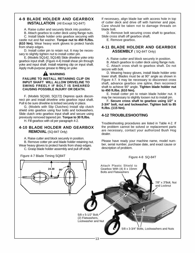
4-9 BLADE HOLDER AND GEARBOXINSTALLATION (All Except SQ-84T)
A. Raise cutter and securely block into position.B. Attach gearbox to cutter deck using flange nuts.C. Install blade holder onto gearbox securing with
castle nut and flat washer. Torque nut to 450 ft./lbs.(610 Nm). Wear heavy work gloves to protect handsfrom sharp edges.
D. Install cotter pin to retain nut. It may be neces-sary to slightly tighten nut to install cotter pin.
E. (Models SQ142, SQ148) Slide driveline yoke ontogearbox input shaft. (Figure 4-4) Install shear pin throughyoke and input shaft. Install retaining clip on input shaft.Apply multi-purpose grease to fitting on yoke
F. (Models SQ160, SQ172) Depress quick discon-nect pin and install driveline onto gearbox input shaft.Pull to be sure driveline is locked securely in place.
G. (Models with Slip Clutches) Install slip clutchshield onto gearbox using four bolts and lockwashers.Slide clutch onto gearbox input shaft and secure usingpreviously removed tapered pin. Torque to 30 ft./lbs.
H. Fill gearbox with oil per paragraph 4-2.
4-10 BLADE HOLDER AND GEARBOXREMOVAL (SQ-84T Only)
A. Raise cutter and block securely in position.B. Remove cotter pin and blade holder retaining nut.
Wear heavy gloves to protect hands from sharp edges.C. Grasp blade holder assembly and pull off shaft.
If necessary, align blade bar with access hole in topof cutter deck and drive off with hammer and pipe.Care should be taken not to damage threads onblade bolt.
D. Remove bolt securing cross shaft to gearbox.Slide cross shaft off gearbox shaft.
E. Remove gearbox.
4-11 BLADE HOLDER AND GEARBOX ASSEMBLY ( SQ-84T Only)
A. Raise cutter and block securely in position.B. Attach gearbox to cutter deck using flange nuts.C. Attach cross shaft to gearbox shaft. Do not
secure with bolt.D. Wearing heavy gloves, install blade holder onto
lower shaft. Blades must be at 90° angle as shown inFigure 4-7. It may be necessary to disconnect crossshaft, advance gearbox one spline, then reconnectshaft to achieve 90° angle. Tighten blade holder nutto 450 ft./lbs. (610 Nm).
E. Install cotter pin to retain blade holder nut. Itmay be necessary to slightly loosen nut to install pin.
F. Secure cross shaft to gearbox using 1/2” x2-3/4” bolt, nut and lockwasher. Tighten bolt to 85ft./lbs. (115 Nm).
4-12 TROUBLESHOOTING
Troubleshooting procedures are listed in Table 4-2. Ifthe problem cannot be solved or replacement partsare necessary, contact your authorized Bush Hogdealer.
Please have ready your machine name, model num-ber, serial number, purchase date, and exact cause ordescription of problem.
Figure 4-8 SQ-84TFigure 4-7 Blade Timing SQ84T
13
5/8 x 3-3/4” Bolts, Lockwashers and Nuts
7/8” x 3”Bolt, Nutand Locknut
5/8 x 5-1/2” Bolt,(2) Flatwashers,Lockwasher and Nut
Attach Plastic Shield toGearbox With (4) 8 x 15mmBolts and Flatwashers
WARNINGFAILURE TO INSTALL RETAINING CLIP ONINPUT SHAFT WILL ALLOW DRIVELINE TOSWING FREELY IF BOLT IS SHEAREDCAUSING POSSIBLE INJURY OR DEATH.
24.38 90°

TABLE 4-2 GENERAL TROUBLESHOOTING
PROBLEM PROBABLE CAUSE REMEDY
Uneven Cut Cutter not level side to side or Refer to SECTION II.front to rear
Worn or bent blades Replace blades per paragraph 4-3.
Stripping or Possible build up of material Clean cutter.Windrowing under cutter
Cutter not level Refer to SECTION II.
Worn blades Replace per paragraph 4-3.
Cutter not being operated Set tractor throttle for properat rated RPM speed PTO speed during operation.
Noisy Cutter Loose components Check all bolts for tightness perTorque Specifications.
Low oil in gearbox Check for proper oil levelRefer to paragraph 4-2.
Rapid blade wear Blade contacting the ground Adjust cutter to operate at a height(cutting edge) that will eliminate ground contact.
Rapid blade wear Cutter not being operated at Set tractor for proper(bolt hole) rated RPM speed PTO speed during operation.
Cutter vibration Cutter not being operated Set tractor throttle for properat rated RPM speed PTO speed during operation.
Blades have unequal weight Replace blades with matched set.
14
15
SECTION VDEALER ASSEMBLY
5-1 ASSEMBLY
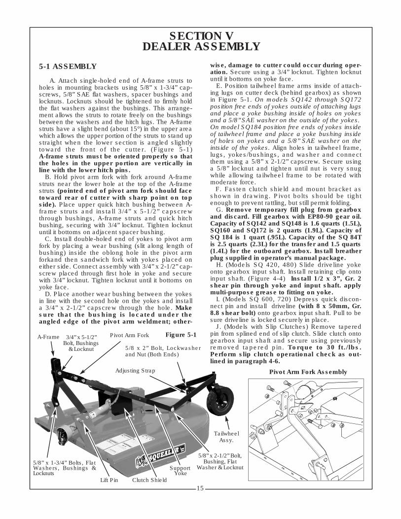
A. Attach single-holed end of A-frame struts toholes in mounting brackets using 5/8” x 1-3/4” cap-screws, 5/8” SAE flat washers, spacer bushings andlocknuts. Locknuts should be tightened to firmly holdthe flat washers against the bushings. This arrange-ment allows the struts to rotate freely on the bushingsbetween the washers and the hitch lugs. The A-framestruts have a slight bend (about 15°) in the upper areawhich allows the upper portion of the struts to stand upstraight when the lower section is angled slightlytoward the front of the cutter. (Figure 5-1)A-frame struts must be oriented properly so thatthe holes in the upper portion are vertically inline with the lower hitch pins.B. Hold pivot arm fork with fork around A-frame
struts near the lower hole at the top of the A-framestruts (pointed end of pivot arm fork should facetoward rear of cutter with sharp point on topside). Place upper quick hitch bushing between A-frame struts and install 3/4” x 5-1/2” capscrewthrough bushings, A-frame struts and quick hitchbushing, securing with 3/4” locknut. Tighten locknutuntil it bottoms on adjacent spacer bushing.C. Install double-holed end of yokes to pivot arm
fork by placing a wear bushing (slit along length ofbushing) inside the oblong hole in the pivot armforkand then sandwich fork with yokes placed oneither side. Connect assembly with 3/4” x 2-1/2” cap-screw placed through first hole in yoke and securewith 3/4” locknut. Tighten locknut until it bottoms onyoke face.D. Place another wear bushing between the yokes
in line with the second hole on the yokes and installa 3/4” x 2-1/2” capscrew through the hole. Makesure that the bushing is located under theangled edge of the pivot arm weldment; other-
wise, damage to cutter could occur during oper-ation. Secure using a 3/4” locknut. Tighten locknutuntil it bottoms on yoke face.E. Position tailwheel frame arms inside of attach-
ing lugs on cutter deck (behind gearbox) as shownin Figure 5-1. On models SQ142 through SQ172position free ends of yokes outside of attaching lugsand place a yoke bushing inside of holes on yokesand a 5/8” SAE washer on the outside of the yokes.On model SQ184 position free ends of yokes insideof tailwheel frame and place a yoke bushing insideof holes on yokes and a 5/8” SAE washer on theintside of the yokes. Align holes in tailwheel frame,lugs, yokes/bushings, and washer and connectthem using a 5/8” x 2-1/2” capscrew. Secure usinga 5/8” locknut and tighten until nut is very snugwhile allowing tailwheel frame to be rotated withmoderate force.F. Fasten clutch shield and mount bracket as
shown in drawing. Pivot bolts should be tightenough to prevent rattling, but still permit folding.G. Remove temporary fill plug from gearbox
and discard. Fill gearbox with EP80-90 gear oil.Capacity of SQ142 and SQ148 is 1.6 quarts (1.5L),SQ160 and SQ172 is 2 quarts (1.9L). Capacity ofSQ 184 is 1 quart (.95L). Capacity of the SQ 84Tis 2.5 quarts (2.3L) for the transfer and 1.5 quarts(1.4L) for the outboard gearbox. Install breatherplug supplied in operator’s manual package.H. (Models SQ 420, 480) Slide driveline yoke
onto gearbox input shaft. Install retaining clip ontoinput shaft. (Figure 4-4) Install 1/2 x 3”, Gr. 2shear pin through yoke and input shaft. applymulti-purpose grease to fitting on yoke.I. (Models SQ 600, 720) Depress quick discon-
nect pin and install driveline (with 8 x 50mm, Gr.8.8 shear bolt) onto gearbox input shaft. Pull to besure driveline is locked securely in place.J. (Models with Slip Clutches) Remove tapered
pin from splined end of slip clutch. Slide clutch ontogearbox input shaft and secure using previouslyremoved tapered pin. Torque to 30 ft./lbs.Perform slip clutch operational check as out-lined in paragraph 4-6.
5/8 x 2” Bolt, Lockwasherand Nut (Both Ends)
5/8” x 2-1/2” Bolt,Bushing, Flat
Washer & Locknut
TailwheelAssy.
Adjusting Strap
Clutch Shield
Pivot Arm Fork
Lift Pin
5/8” x 1-3/4” Bolts, FlatWashers, Bushings &Locknuts
A-Frame 3/4” x 5-1/2”Bolt, Bushings& Locknut
Figure 5-1
SupportYoke
Pivot Arm Fork Assembly

5-2 OPTIONAL FRONT SHIELDINGINSTALLATION (SQ 420, 480, 600, 720, 840)
A. Install front belting to deck lip angle securingwith 3/8 x 1-1/4” bolts, flatwashers and locknuts.(SQ184 uses 3/8 x 3-1/2” bolts) Bolt heads shouldbe to the outside of the deck. (Figure 5-3)
Figure 5-3 Front Belting
5-3 OPTIONAL FRONT SHIELDING INSTALLATION (SQ84T)
A. Install front shield to deck lip angle securingwith six 3/8 x 1-1/4” carriage bolts, flatwashers, lock-washers and nuts. (Figure 5-4) Carriage bolts shouldbe installed from top of lip angle.
B. Install right and left side shield to skid usingtwo 3/8 x 1-1/4” carriage bolts, flatwashers, lock-washers, and nuts.
Figure 5-4 SQ84T Front Shielding
B. SQ142 & 148 use the same fasteners in alllocations around the rear band. Fasten with 3/8 x 1”capscrews, flatwashers, lockwashers and nuts.(Figure 5-5)
SQ160, 172, & 184 require longer bolts at the outerends of the rear bands. Fasten the ends with 3/8 x1-1/2” capscrews, flatwashers, lockwashers andnuts. The remaining locations around the band use3/8 x 1” capscrews, flatwashers, lockwashers andnuts.
Side Shield Front ShieldSkid
3/8 x 1-1/4” Carriage Bolts Underside of Deck
Rear Band3/8 x 1” Capscrews
16
3/8 x 1-1/4” Bolts Lip Angle
5-5 FRONT AND REAR CHAININSTALLATION
Install chain sections in the same manner as thefront belting and rear bands. The rear safety chainsuse only one bolt at each end.
5-4 OPTIONAL REAR BAND INSTALLA-TION (SQ142, 148, 160, 172, 184)
A. Align deflector band with holes in rear band ofdeck.
WARNINGCUTTER MUST BE EQUIPPED WITH FRONTAND REAR BANDS WHEN OPERATING INTHE VICINITY OF HIGHWAYS OR IN ANYAREA WHERE PEOPLE MAY BE PRESENT
Figure 5-7 Rear Chain Assembly
Figure 5-6 Front Chain Assembly
Figure 5-5 Rear Band
Mount Bracket
Shield
BreatherPlug
8mm x 1-1/4” Bolt,Lockwasher& Flatwasher
3/8 x 1-1/4” Bolt, Flatwashers& Locknut (Each Side)
Figure 5-2

5-6 SQ84T REAR BAND INSTALLATION
A. Fasten band to rear middle of deck using 3/8 x1” bolts, flatwashers, lockwashers and nuts in exist-ing holes. Lip angle must be to the bottom andextending away from the deck.
B. Bend the sides of band around the rear of thecutter. (Figure 5-5)
C. Fasten the remaining holes. (Figure 5-6)
WARNING
CUTTER MUST BE EQUIPPED WITH FRONTAND REAR BANDS WHEN OPERATING INTHE VICINITY OF HIGHWAYS OR IN ANYAREA WHERE PEOPLE MAY BE PRESENT.
Figure 5-7
Bend Bands Into Place
Figure 5-8 Tighten All Fasteners
Figure 5-9 Rear Band Installed
5-7 SQ84T GEARBOX INPUT SHIELD
Install slip clutch shield onto gearbox using four 8x 15mm bolts and flatwashers which are included inthe Operator’s Manual package. (Figure 5-10)
Plastic Slip Clutch Shield
17
Figure 5-10SQ84T Slip Clutch Shield
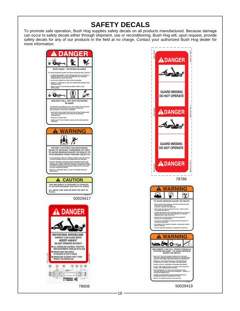
SAFETY DECALSTo promote safe operation, Bush Hog supplies safety decals on all products manufactured. Because damagecan occur to safety decals either through shipment, use or reconditioning, Bush Hog will, upon request, providesafety decals for any of our products in the field at no charge. Contact your authorized Bush Hog dealer formore information.
18
50029419
50029417
78786
78608 50029419

TORQUE SPECIFICATIONSProper toque for American fasteners used on Bush Hog equipment.
Recommended Torque in Foot Pounds (Newton Meters).*
BOLT DIAMETERWRENCH (IN.) “B” AND SAE SAE SAE
SIZE (IN.) “A” THREAD SIZE GRADE 2 GRADE 5 GRADE 8
7/16 1/4 - 2O UNC 6 (7) 8 (11) 12 (16)
7/16 1/4 - 28 UNF 6 (8) 10 (13) 14 (18)
1/2 5/16 - 18 UNC 11 (15) 17 (23) 25 (33)
1/2 5/16 - 24 UNF 13 (17) 19 (26) 27 (37)
9/16 3/8 - 16 UNC 20 (27) 31 (42) 44 (60)
9/16 3/8 - 24 UNF 23 (31) 35 (47) 49 (66)
5/8 7/16 - 14 UNC 32 (43) 49 (66) 70 (95)
5/8 7/16 - 20 UNF 36 (49) 55 (75) 78 (106)
3/4 1/2 - 13 UNC 49 (66) 76 (103) 106 (144)
3/4 1/2 - 20 UNF 55 (75) 85 (115) 120 (163)
7/8 9/16 - 12 UNC 70 (95) 109 (148) 153 (207)
7/8 9/16 - 18 UNF 79 (107) 122 (165) 172 (233)
15/16 5/8 - 11 UNC 97 (131) 150 (203) 212 (287)
15/16 5/8 - 18 UNF 110 (149) 170 (230) 240 (325)
1-1/8 3/4 - 10 UNC 144 (195) 266 (360) 376 (509)
1-1/8 3/4 - 16 UNF 192 (260) 297 (402) 420 (569)
1-5/16 7/8 - 9 UNC 166 (225) 430 (583) 606 (821)
1-5/16 7/8 - 14 UNF 184 (249) 474 (642) 668 (905)
1-1/2 1 - 8 UNC 250 (339) 644 (873) 909 (1232)
1-1/2 1 - 12 UNF 274 (371) 705 (955) 995 (1348)
1-1/2 1 - 14 UNF 280 (379) 721 (977) 1019 (1381)
1-11/16 1-1/8 - 7 UNC 354 (480) 795 (1077) 1288(1745)
1-11/16 1-1/8 - 12 UNF 397 (538) 890 (1206) 1444 (1957)
1-7/8 1-1/4 - 7 UNC 500 (678) 1120 (1518) 1817 (2462)
1-7/8 1-1/4 - 12 UNF 553 (749) 1241 (1682) 2013 (2728)
2-1/16 1-3/8 - 6 UNC 655 (887) 1470 (1992) 2382 (3228)
2-1/16 1-3/8 - 12 UNF 746 (1011) 1672 (2266) 2712 (3675)
2-1/4 1-1/2 - 6 UNC 870 (1179) 1950 (2642) 3161 (4283)
2-1/4 1-1/2 - 12 UNF 979 (1327) 2194 (2973) 3557 (4820)
Proper torque for metric fasteners used on Bush Hog equipment.Recommended torque in foot pounds (newton Meters).*
WRENCH BOLTSIZE DIA. ASTM ASTM ASTM ASTM
(mm) “A” (mm) “B” 4.6 8.8 9.8 10.9
8 5 1.8 (2.4) 5.1 (6.9) 6.5 (8.8)
10 6 3 (4) 8.7 (12) 11.1 (15)
13 8 7.3 (10) 21.1 (29) 27 (37)
16 10 14.5 (20) 42 (57) 53 (72)
18 12 25 (34) 74 (100) 73 (99) 93 (126)
21 14 40 (54) 118 (160) 116 (157) 148 (201)
24 16 62 (84) 167 (226) 181 (245) 230 (312)
30 20 122 (165) 325 (440) 449 (608)
33 22 443 (600) 611 (828)
36 24 211 (286) 563 (763) 778 (1054)
41 27 821 (1112) 1138 (1542)
46 30 418 (566) 1119 (1516) 1547 (2096)
*Use 75% of the specified torque value for platedfasteners. Use 85% of the specified torquevalues for lubricated fasteners.
Numbers appearing on bolt headsindicate ASTM class.
METRIC
AMERICANBolt Head Markings
WrenchSize “A”
Bolt
Diameter “B”
SAE Grade 8(6 Dashes)
SAE Grade 2(No Dashes)
SAE Grade 5(3 Dashes)
WrenchSize “A” 8.8
Bolt
Diameter “B”
19

20
BUSH HOG SQUEALER SLIP CLUTCHESBush Hog Squealer Rotary Cutters are subject to having either “Bondioli &Pavesi / Binacchi” or “EG / Comer” slip clutches installed. While these clutchesare similar, the spring length settings are different. Refer to the photographsbelow to help identify which brand of clutch you are adjusting. Notice the“Bondioli & Pavesi / Binacchi” clutches have solid castings, whereas the“EG / Comer” castings have centrally located holes through them.
BONDIOLI & PAVESI / BINACCHI(Solid Casting)
EG / COMER(Holes Through Centers)
Spring LengthsModels SQ-600, SQ-720, SQ-840 & SQ-84T
Bondioli & Pavesi EG/Comeror Binacchi
1.10” (28 mm) 1.26” (32 mm)
SeeChart


P.O. Box 1039 ● Selma, AL 36702-1039Telephone (334) 874-2700 ● www.bushhog.com