Embed Size (px)
Citation preview

Sputtering

Vacuum Evaporation Recap
• Use high temperatures at high vacuum to evaporate (eject) atoms or molecules off a material surface.
• Use ballistic flow to transport them to a substrate and deposit.
• Film uniformity can be an issue.• Alloy evaporation is very complicated and
in most cases, not possible.
An Alternative Method• Instead of using heat to eject
material from a source, we can bombard them with high speed particles.
• The momentum transfer from the particles to the surface atoms can impart enough energy to allow the surface atoms to escape.
• Once ejected, these atoms (or molecules) can travel to a substrate and deposit as a film.
• There are several considerations here:– Creating, controlling and directing a high speed particle stream.– Interaction of these particles with the source surface and emission
yields.– Deposition of the emitted atoms on the substrate and film quality.
Source
Substrate

Some Terminology
• Atomic particles can best be easily controlled by electromagnetic methods if they are charged. A weakly charged gas of particles that exhibit collective behavior is called a plasma.
• The source material is called the target and the emitted atoms or molecules are said to be sputtered off.

Sputtering• So in sputtering, the target
material and the substrate is placed in a vacuum chamber.
• A voltage is applied between them so that the target is the cathode and the substrate is attached to the anode.
• A plasma is created by ionizing a sputtering gas (generally a chemically inert, heavy gas like Argon).
• The sputtering gas bombards the target and sputters off the material we’d like to deposit.
-V
Target (cathode)
Substrates
Anode
Sputtering gas
Plasma

Generating and Controlling the Plasma
• Ions can be generated by the collision of neutral atoms with high energy electrons.
• The interaction of the ions and the target are determined by the velocity and energy of the ions.
• Since ions are charged particles, electric and magnetic fields can control these parameters.
• The process begins with a stray electron near the cathode is accelerated towards the anode and collides with a neutral gas atom converting it to a positively charged ion.
• The process results in two electrons which can then collide with other gas atoms and ionize them creating a cascading process until the gas breaks down.
• The breakdown voltage depends on the pressure in the chamber and the distance between the anode and the cathode.
• At too low pressures, there aren’t enough collisions between atoms and electrons to sustain a plasma.
• At too high pressures, there so many collisions that electrons do not have enough time to gather energy between collisions to be able to ionize the atoms.
+−− +→+ AeAe 2
VB
Pd

Glow Discharge Formation• Initially the current (charge flow) is small. As charges
multiply the current increases rapidly but the voltage, limited by supply, remains constant.
• Eventually, there are enough ions and charges for the plasma to be self-sustaining.
• Some of the electron-atom collisions will produce light instead of electrons and ions and the plasma will also glow accompanied by a voltage drop (normal glow)
• If the input power is increased further, the current density becomes uniform across the cathode and we’ll be in the abnormal discharge regime. This is where sputtering operates.

The Glow Discharge
Cathode (-) Anode (+)
Cathode Glow
•Large field strength•Many collisions with the cathode leads to high intensity glow
Cathode Dark Space
•Electrons have too much energy•No light emission due to mismatch of electron energies to ionization levels
Negative Glow
•Due to reduced density, electric field strength becomes weak•Electrons have the right energy to cause excitation
Faraday Dark Space
•Electron energy is reduced from the collisions in the negative glow region
Positive Glow
•Main plasma region•Uniform field strength•Equal number of electrons and ions
Aston Dark Space
•Low energy electrons and high energy ions
Anode Dark Space
Substrate

Plasma Pressures• Unless there are enough collisions, the plasma will
quickly die.• In order to have a self-sustaining plasma, each electron
has to generate enough secondary emission.• Since we want collisions to occur, the pressure can not
be too low.– The mean free path should be a tenth or less than the typical
size of the chamber.• Also, since we want the electrons to gain enough energy
between collisions, the pressure can not be too high.• This means discharge tube pressures around 10-1000
mTorr and plasma densities around 1010 – 1012 cm-3.

Ion-Surface Interactions• When ions bombard a surface, several things can
happen:– Reflection– Sticking (adsorption)– Sputtering– Ion implantation– Chemical reactions– Electron and photon emission
• The ion beam energy is the critical parameter.– < 5 eV : Adsorption or reflection– 5 - 10 eV : Surface damage and migration– 10 - 3 keV : Sputtering– > 10 keV : Ion implantation

How Ions Sputter Atoms• When ions collide with surface atoms on the target, the
energy transfer can knock some of these atoms off the surface.
• The key principle is energy and momentum conservation.
• In any collision, momentum is conserved.• If the collision is elastic, kinetic energy is also conserved.• The energies required for sputtering are much higher
than lattice bonding or vibrational energies (which are the causes of inelastic interactions), therefore sputtering collisions can be considered elastic.

Momentum and Energy
• Maximum energy transfer in such a collision occurs when the masses are equal.
vp m= 2
21 mvK =
iii mm 2211 vvp += fff mm 2211 vvp +==
( )222
2112
1iii vmvmK += ( )2
222
1121
fff vmvmK +==
m1 ,v1i
m2 ,v2i
m2 ,v2fm1 ,v1f Momentum Kinetic Energy
( )θ2
221
21
1
2 cos4mmmm
KK
+∝
m1
m2K1
K2
θ
Energy Transfer Between Two Masses in the Forward Direction
m1/m2
0.0 0.5 1.0 1.5 2.0 2.5
K1/K
20.0
0.2
0.4
0.6
0.8
1.0
1.2

Direction of Emission• For normal incidence of
ions, the primary collision can not eject an atom off the surface.
• However, the secondary collision can.
• At oblique incidence, primary collisions can result in ejection.– Think billiard balls.

Various Sputtering Regimes• Single Knock-On
– The initial ion-surface collision sets target atoms in motion. If enough energy is transferred, binding forces can be overcome. Typical threshold energies are in the 10 - 30 eV range.
• Linear Collision Cascade– At higher ion energies (100
eV - 10 keV) recoil is minimal and a cascading effect produces sputtering.

Sputter Yield
• S depends on– type of target atom– binding energy of target atoms– relative mass of ions and atoms – incident ion energy– angle of incidence of ions
• S can range from 0.1 to 10
ionsincident ofNumber atoms sputtered ofNumber
=S
θ
ionsS
θ90060-70
S
E (eV)~1000

Angular and Energy Distribution of Ejected Atoms
• Sputtered atoms have relatively small energies, typically between 2 - 7 eV (in thermal evaporation, these values are even smaller, around 0.1 eV).
• The number distribution as a function of energy is Boltzmann like.
• The angular distribution is cosine-like and depends on ion energy, the target’s type and crystallography.
Target
(Cos θ) Dependence –Low ion energies, isotropic flux, better step coverage
(Cosnθ) Dependence –High ion energies, higher directionality, poor step coverage

Deposition
• Sputtered atoms from the target make their way on to the substrate through diffusion.
• Ions and neutralized gas atoms may also embed on the substrate as impurities.
• The ions incident on the substrate may also re-sputter the surface.
• Chemical reactions may occur.
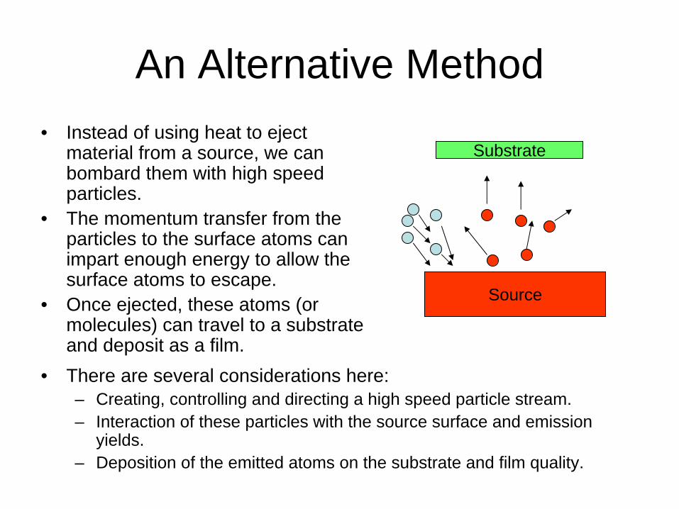
Deposition Rate
• It is proportional to the sputtering yield.
• An optimum pressure exists for high deposition rates.– Higher pressure means
more collisions and ions.– Lower pressure means
less scattering.

Alloy Composition Issues• If a target is made up of several atoms with different
sputtering yields, initial film composition can be off.• However, sputtering yield variations are smaller
compared to vapor pressure variations. Therefore the initial layers of film will be more closely related to the target composition.
• Also, since temperatures are lower and melting is not an issue, diffusive homogenization at the substrate is less likely.
• Finally, any initial disparities will eventually correct themselves as the amount of the faster sputtering component at the target reduces.

Compound Issues• While most of the previous discussion is
applicable to compounds there is an interesting issue.
• If the target temperature is too low, ion bombardment can result in amorphization of crystalline targets and isotropic sputtering.
• Increasing the target temperature anneals the surface as it sputters, thereby keeping the crystalline structure and a more directional sputtering.

Step Coverage and Film Uniformity
• Angular distribution of sputtering depends on the pressure.
• Lower pressures result in a more directed flow which results in less uniform films.
• Higher pressures result in more isotropic flow and better coverage.
• Uniform films also require larger targets.

Some Parameters• Argon Pressure
– optimum deposition rate around 100 mTorr– compromise between
• increasing number of Ar ions • increasing scattering of Ar ions with neutral Ar atoms
– if you can increase the number of ions without increasing the number of neutrals, you can operate at lower pressures
• Sputter voltage– maximize sputter yield (S) – typically -2 to -5 kV
• Substrate Bias Voltage– substrate is being bombarded by electrons and ions from target and
plasma • sputtering film while you deposit
– neutral atoms deposit independently – put negative bias on the substrate to control this – can significantly change film properties
• Substrate temperature– control with substrate heater – heating from deposited material
• increases with increasing sputter voltage • decreases with increasing substrate bias
• Particle Energy– increases with increasing sputter voltage – decreases with increasing substrate bias – decreases with increasing Ar pressure
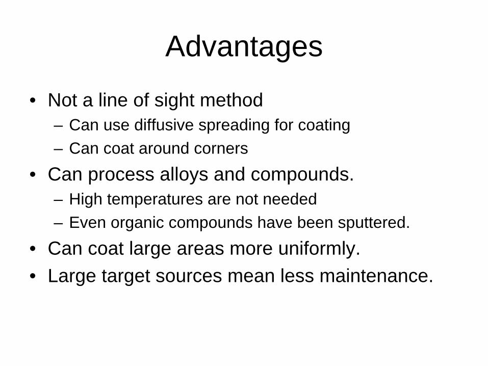
Advantages
• Not a line of sight method– Can use diffusive spreading for coating– Can coat around corners
• Can process alloys and compounds.– High temperatures are not needed– Even organic compounds have been sputtered.
• Can coat large areas more uniformly.• Large target sources mean less maintenance.