Embed Size (px)
Citation preview
1
MECHANICAL DRIVES:
Two groups,
They are
1. Drives that transmit power by means of friction: eg: belt drives and rope drives.
2. Drives that transmit power by means of engagement: eg: chain drives and gear drives.
However, the selection of a proper mechanical drive for a given application depends
upon number of factors such as centre distance, velocity ratio, shifting arrangement,
Maintenance and cost.
GEAR DRIVES
Gears are defined as toothed wheels, which transmit power and motion from one shaft to
another by means of successive engagement of teeth
1. The centre distance between the shafts is relatively small.
2. It can transmit very large power
3. It is a positive, and the velocity ratio remains constant.
4. It can transmit motion at a very low velocity.
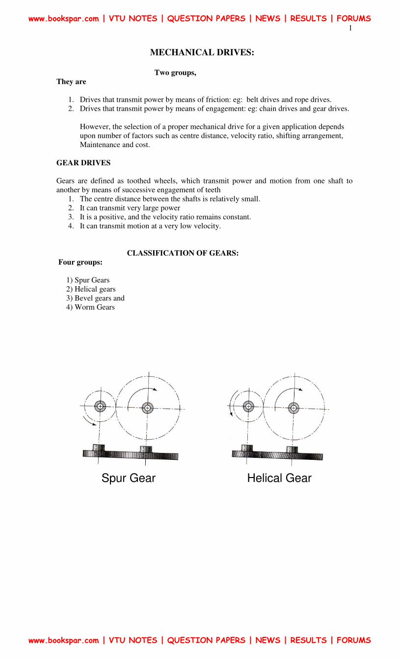
CLASSIFICATION OF GEARS:
Four groups:
1) Spur Gears
2) Helical gears
3) Bevel gears and
4) Worm Gears
Spur Gear Helical Gear
www.bookspar.com | VTU NOTES | QUESTION PAPERS | NEWS | RESULTS | FORUMS
www.bookspar.com | VTU NOTES | QUESTION PAPERS | NEWS | RESULTS | FORUMS
2
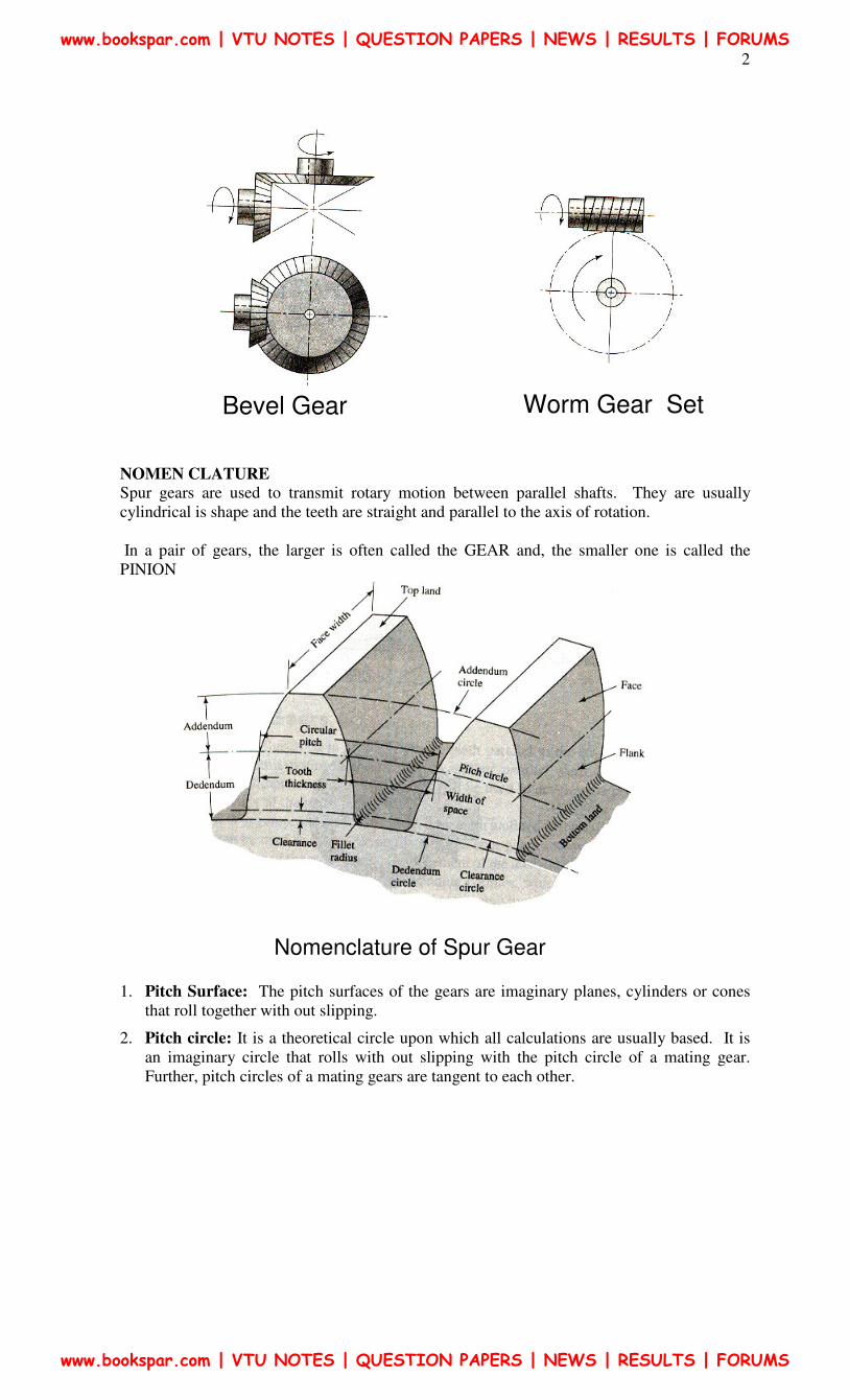
NOMEN CLATURE
Spur gears are used to transmit rotary motion between parallel shafts. They are usually
cylindrical is shape and the teeth are straight and parallel to the axis of rotation.
In a pair of gears, the larger is often called the GEAR and, the smaller one is called the
PINION
1. Pitch Surface: The pitch surfaces of the gears are imaginary planes, cylinders or cones
that roll together with out slipping.
2. Pitch circle: It is a theoretical circle upon which all calculations are usually based. It is
an imaginary circle that rolls with out slipping with the pitch circle of a mating gear.
Further, pitch circles of a mating gears are tangent to each other.
Bevel Gear Worm Gear Set
Nomenclature of Spur Gear
www.bookspar.com | VTU NOTES | QUESTION PAPERS | NEWS | RESULTS | FORUMS
www.bookspar.com | VTU NOTES | QUESTION PAPERS | NEWS | RESULTS | FORUMS
3
3. Pitch circle diameter: The pitch circle diameter is the diameter of pitch circle. Normally,
the size of the gear is usually specified by pitch circle diameter. This is denoted by “d”
4. Top land: The top land is the surface of the top of the gear tooth
5. Base circle: The base circle is an imaginary circle from which the involute curve of the
tooth profile is generated (the base circles of two mating gears are tangent to the pressure
line)
6. Addendum: The Addendum is the radial distance between the pitch and addendum
circles. Addendum indicates the height of tooth above the pitch circle.
7. Dedendum: The dedendum is the radial distance between pitch and the dedendum circles.
Dedendum indicates the depth of the tooth below the pitch circle.
8. Whole Depth: The whole depth is the total depth of the tooth space that is the sum of
addendum and Dedendum.
9. Working depth: The working depth is the depth of engagement of two gear teeth that is
the sum of their addendums
10. Clearance: The clearance is the amount by which the Dedendum of a given gear exceeds
the addendum of it’s mating tooth.
11. Face: The surface of the gear tooth between the pitch cylinder and the addendum cylinder
is called face of the tooth.
12. Flank: The surface of the gear tooth between the pitch cylinder and the root cylinder is
called flank of the tooth.
13. Face Width: is the width of the tooth measured parallel to the axis.
14. Fillet radius: The radius that connects the root circle to the profile of the tooth is called
fillet radius.
15. Circular pitch: is the distance measured on the pitch circle, from a point on one tooth to a
corresponding point on an adjacent tooth.
16. Circular tooth thickness: The length of the arc on pitch circle subtending a single gear
tooth is called circular tooth thickness. Theoretically circular tooth thickness is half of
circular pitch.
17. Width of space: (tooth space) The width of the space between two adjacent teeth
measured along the pitch circle. Theoretically, tooth space is equal to circular tooth
thickness or half of circular pitch
18. Working depth: The working depth is the depth of engagement of two gear teeth, that is
the sum of their addendums
19. Whole depth: The whole depth is the total depth of the tooth space, that is the sum of
addendum and dedendum and (this is also equal to whole depth + clearance)
20. Centre distance: it is the distance between centres of pitch circles of mating gears. (it is
also equal to the distance between centres of base circles of mating gears)
21. Line of action: The line of action is the common tangent to the base circles of mating
gears. The contact between the involute surfaces of mating teeth must be on this line to
give smooth operation. The force is transmitted from the driving gear to the driven gear on
this line.
22. Pressure angle: It is the angle that the line of action makes with the common tangent to
the pitch circles.
www.bookspar.com | VTU NOTES | QUESTION PAPERS | NEWS | RESULTS | FORUMS
www.bookspar.com | VTU NOTES | QUESTION PAPERS | NEWS | RESULTS | FORUMS
4
23. Arc of contact: Is the arc of the pitch circle through which a tooth moves from the
beginning to the end of contact with mating tooth.
24. Arc of approach: it is the arc of the pitch circle through which a tooth moves from its
beginning of contact until the point of contact arrives at the pitch point.
25. Arc of recess: It is the arc of the pitch circle through witch a tooth moves from the
contact at the pitch point until the contact ends.
26. Contact Ratio?
Velocity ratio: if the ratio of angular velocity of the driving gear to the angular velocity of
driven gear. It is also called the speed ratio.
27. Module: It is the ratio of pitch circle diameter in mith meters to the number of teeth. it is
usually denoted by ‘m’ Mathematically
Z
Dm =
28. Back lash: It is the difference between the tooth space and the tooth thickness as
measured on the pitch circle.
29. Velocity Ratio: Is the ratio of angular velocity of the driving gear to the angular velocity
of driven gear. It is also called the speed ratio.
www.bookspar.com | VTU NOTES | QUESTION PAPERS | NEWS | RESULTS | FORUMS
www.bookspar.com | VTU NOTES | QUESTION PAPERS | NEWS | RESULTS | FORUMS
5
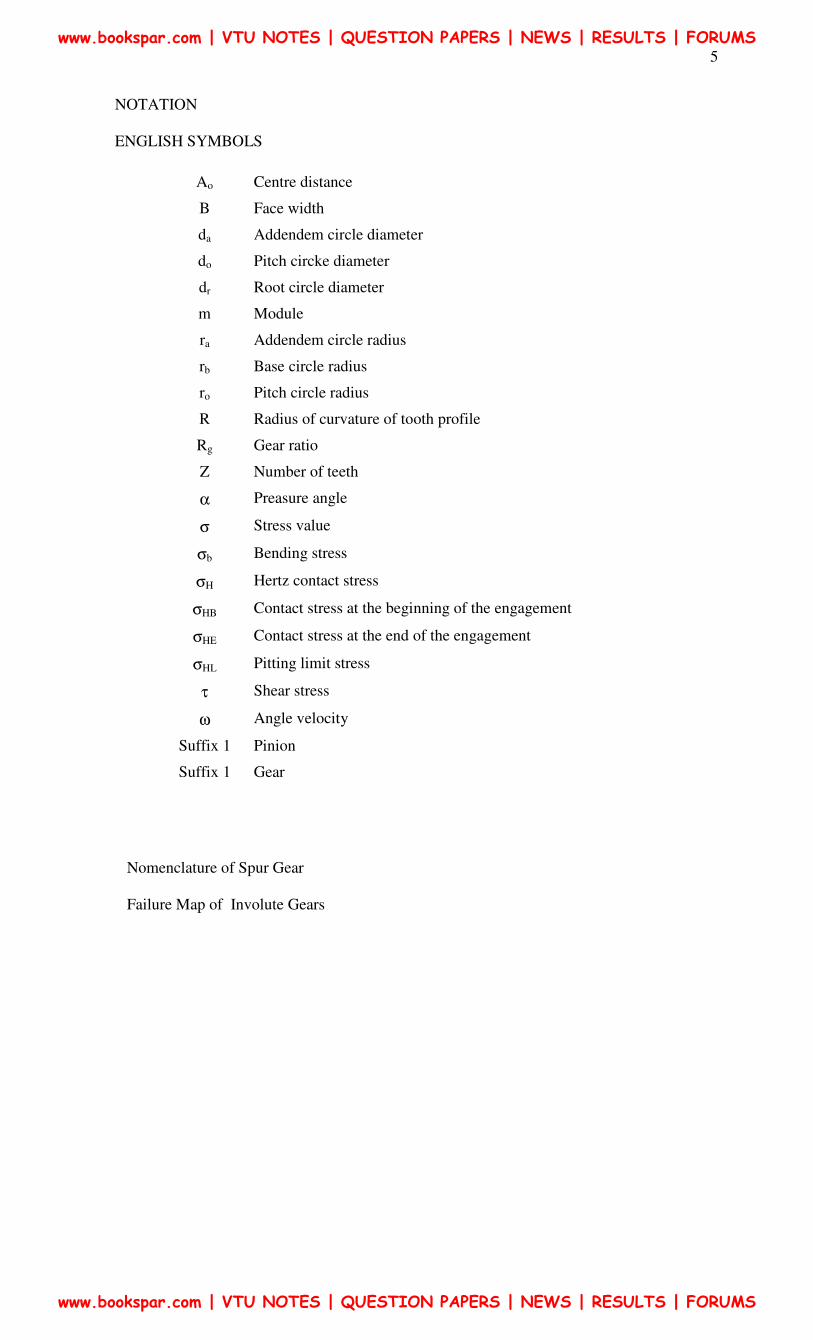
NOTATION
ENGLISH SYMBOLS
Ao Centre distance
B Face width
da Addendem circle diameter
do Pitch circke diameter
dr Root circle diameter
m Module
ra Addendem circle radius
rb Base circle radius
ro Pitch circle radius
R Radius of curvature of tooth profile
Rg Gear ratio
Z Number of teeth
α Preasure angle
σ Stress value
σb Bending stress
σH Hertz contact stress
σHB Contact stress at the beginning of the engagement
σHE Contact stress at the end of the engagement
σHL Pitting limit stress
τ Shear stress
ω Angle velocity
Suffix 1 Pinion
Suffix 1 Gear
Nomenclature of Spur Gear
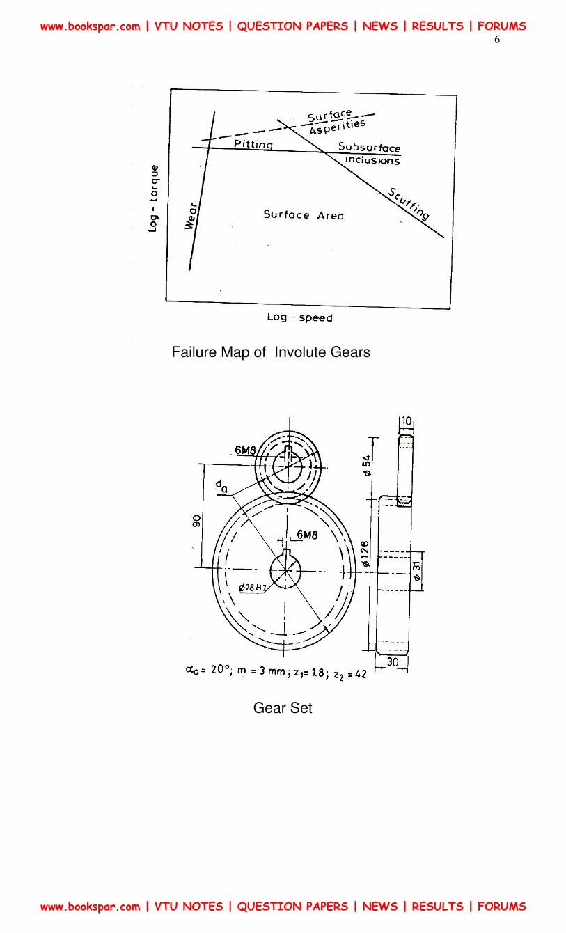
Failure Map of Involute Gears
www.bookspar.com | VTU NOTES | QUESTION PAPERS | NEWS | RESULTS | FORUMS
www.bookspar.com | VTU NOTES | QUESTION PAPERS | NEWS | RESULTS | FORUMS
6
Failure Map of Involute Gears
Gear Set
www.bookspar.com | VTU NOTES | QUESTION PAPERS | NEWS | RESULTS | FORUMS
www.bookspar.com | VTU NOTES | QUESTION PAPERS | NEWS | RESULTS | FORUMS
7
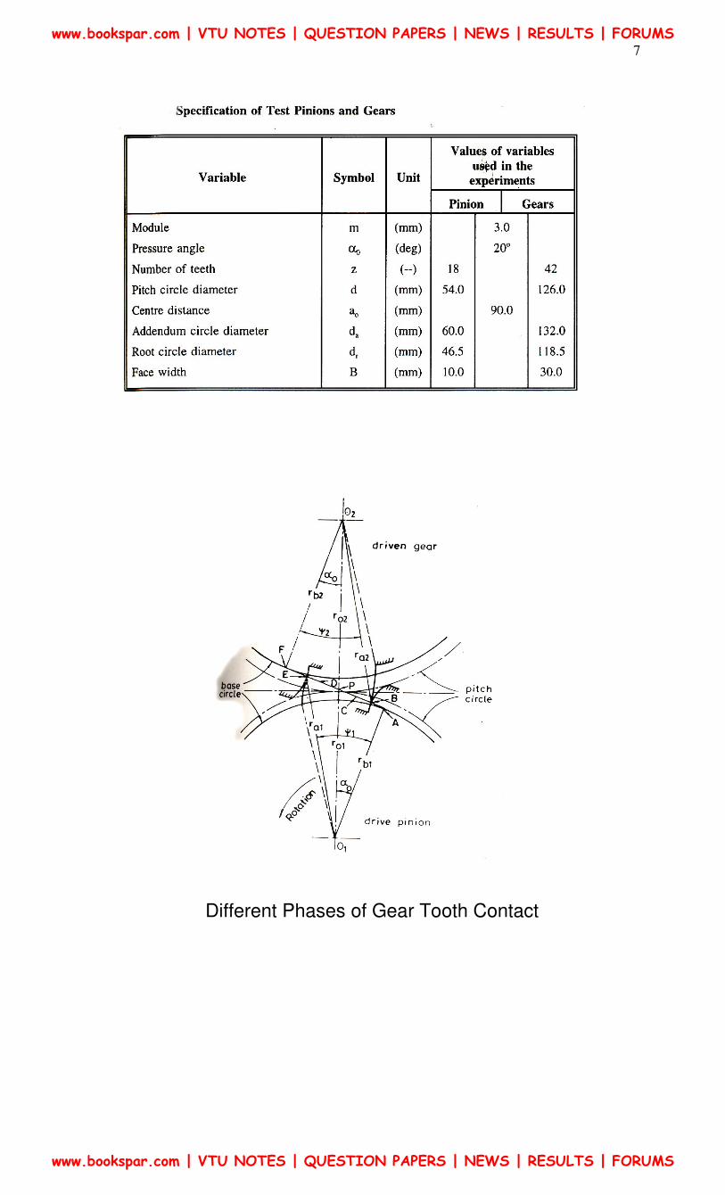
Different Phases of Gear Tooth Contact
www.bookspar.com | VTU NOTES | QUESTION PAPERS | NEWS | RESULTS | FORUMS
www.bookspar.com | VTU NOTES | QUESTION PAPERS | NEWS | RESULTS | FORUMS
8
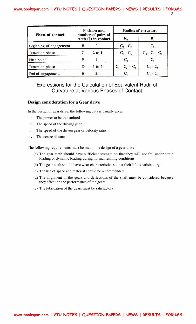
Design consideration for a Gear drive
In the design of gear drive, the following data is usually given
i. The power to be transmitted
ii. The speed of the driving gear
iii. The speed of the driven gear or velocity ratio
iv. The centre distance
The following requirements must be met in the design of a gear drive
(a) The gear teeth should have sufficient strength so that they will not fail under static
loading or dynamic loading during normal running conditions
(b) The gear teeth should have wear characteristics so that their life is satisfactory.
(c) The use of space and material should be recommended
(d) The alignment of the gears and deflections of the shaft must be considered because
they effect on the performance of the gears
(e) The lubrication of the gears must be satisfactory
Expressions for the Calculation of Equivalent Radii of Curvature at Various Phases of Contact
www.bookspar.com | VTU NOTES | QUESTION PAPERS | NEWS | RESULTS | FORUMS
www.bookspar.com | VTU NOTES | QUESTION PAPERS | NEWS | RESULTS | FORUMS
9
Selection of Gears:
The first step in the design of the gear drive is selection of a proper type of gear for a given
application. The factors to be considered for deciding the type of the gear are
� General layout of shafts
� Speed ratio
� Power to be transmitted
� Input speed and
� Cost
1. Spur & Helical Gears – When the shaft are parallel
2. Bevel Gears – When the shafts intersect at right angles, and,
3. Worm & Worm Gears – When the axes of the shaft are perpendicular and not
intersecting. As a special case, when the axes of the two shafts are neither intersecting nor
perpendicular crossed helical gears are employed.
The speed reduction or velocity ratio for a single pair of spur or helical gears is normally
taken as 6: 1. On rare occasions this can be raised to 10: 1. When the velocity ratio increases,
the size of the gear wheel increases. This results in an increase in the size of the gear box and
the material cost increases. For high speed reduction two stage or three stage construction are
used.
The normal velocity ratio for a pair of bend gears is 1: 1 which can be increased to 3: 1 under
certain circumstances.
For high-speed reduction worm gears offers the best choice. The velocity ratio in their case is
60: 1, which can be increased to 100: 1. They are widely used in materials handling
equipment due to this advantage.
Further, spur gears generate noise in high-speed applications due to sudden contact over the
entire face with between two meeting teeth. Where as, in helical gears the contact between
the two meshing teeth begans with a point and gradually extends along the tooth, resulting in
guite operations.
From considerations spurgears are the cheapest. They are not only easy to manufacture but
there exists a number of methods to manufacture them. The manufacturing of helical, bevel
and worm gears is a specialized and costly operation.
Low of Gearing:
The fundamental law of gearing states “The common normal to the both profile at the point of
contact should always pass through a fixed point called the pitch point, in order to obtain a
constant velocity ratio.
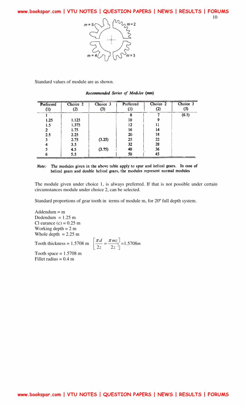
MODULE:
The module specifies the size of gear tooth. Figure shows the actual sizes of gear tooth with
four different modules. It is observed that as the modules increases, the size of the gear tooth
also increases. It can be said that module is the index of the size of gear tooth.
www.bookspar.com | VTU NOTES | QUESTION PAPERS | NEWS | RESULTS | FORUMS
www.bookspar.com | VTU NOTES | QUESTION PAPERS | NEWS | RESULTS | FORUMS
10
Standard values of module are as shown.
The module given under choice 1, is always preferred. If that is not possible under certain
circumstances module under choice 2, can be selected.
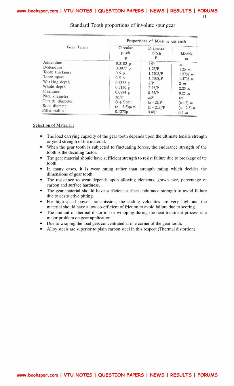
Standard proportions of gear tooth in terms of module m, for 20º full depth system.
Addendum = m
Dedendum = 1.25 m
Cl earance (c) = 0.25 m
Working depth = 2 m
Whole depth = 2.25 m
Tooth thickness = 1.5708 m mz
mz
z
d5708.1
22=
=
ππ
Tooth space = 1.5708 m
Fillet radius = 0.4 m
www.bookspar.com | VTU NOTES | QUESTION PAPERS | NEWS | RESULTS | FORUMS
www.bookspar.com | VTU NOTES | QUESTION PAPERS | NEWS | RESULTS | FORUMS
11
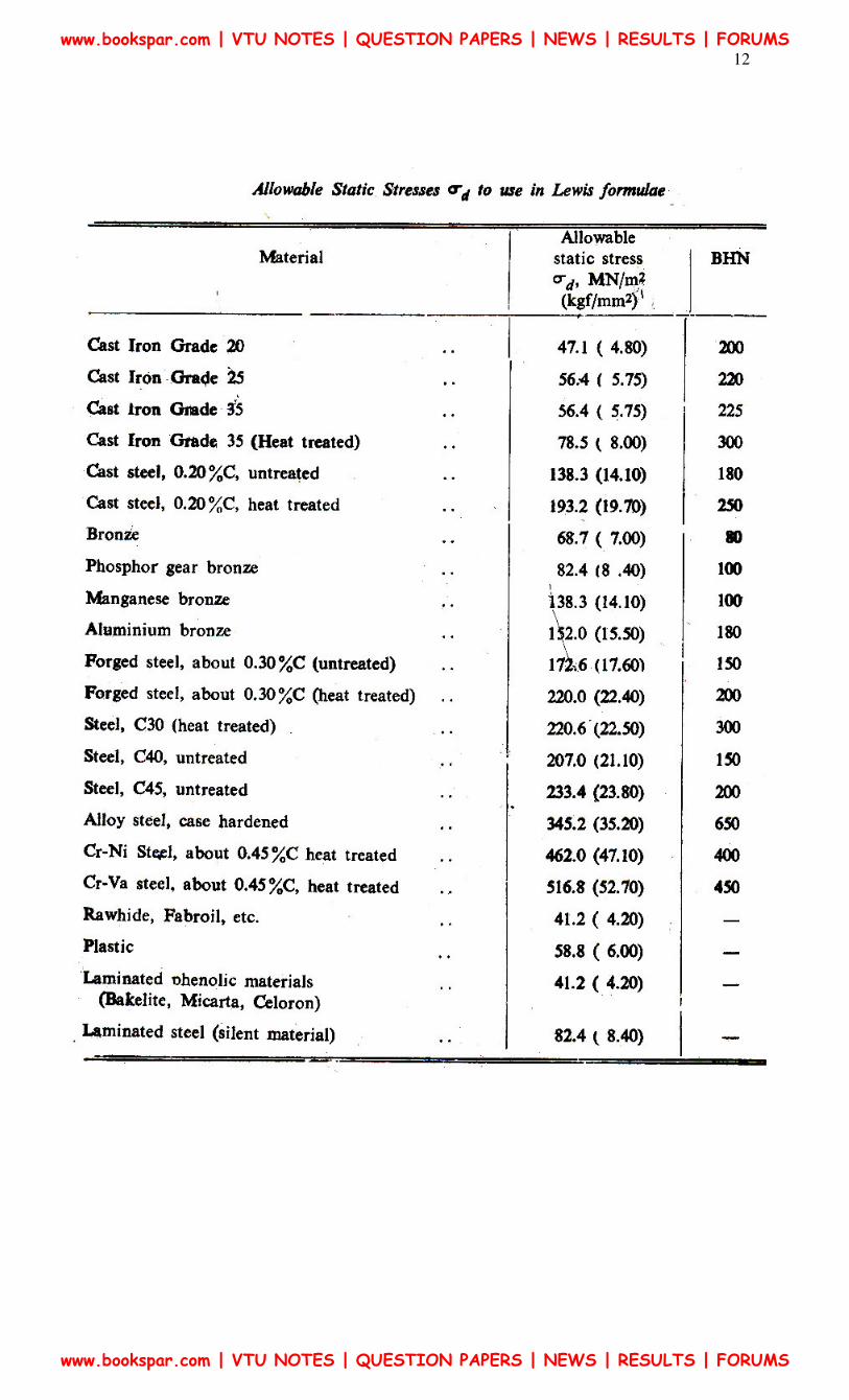
Selection of Material :
• The load carrying capacity of the gear tooth depends upon the ultimate tensile strength
or yield strength of the material.
• When the gear tooth is subjected to fluctuating forces, the endurance strength of the
tooth is the deciding factor.
• The gear material should have sufficient strength to resist failure due to breakage of tte
tooth.
• In many cases, it is wear rating rather than strength rating which decides the
dimensions of gear tooth.
• The resistance to wear depends upon alloying elements, grawn size, percentage of
carbon and surface hardness.
• The gear material should have sufficient surface endurance strength to avoid failure
due to destructive pitting.
• For high-speed power transmission, the sliding velocities are very high and the
material should have a low co-efficient of friction to avoid failure due to scoring.
• The amount of thermal distortion or wrapping during the heat treatment process is a
major problem on gear application.
• Due to wraping the load gets concentrated at one corner of the gear tooth.
• Alloy steels are superior to plain carbon steel in this respect (Thermal distortion)
Standard Tooth proportions of involute spur gear
www.bookspar.com | VTU NOTES | QUESTION PAPERS | NEWS | RESULTS | FORUMS
www.bookspar.com | VTU NOTES | QUESTION PAPERS | NEWS | RESULTS | FORUMS
12
www.bookspar.com | VTU NOTES | QUESTION PAPERS | NEWS | RESULTS | FORUMS
www.bookspar.com | VTU NOTES | QUESTION PAPERS | NEWS | RESULTS | FORUMS
13
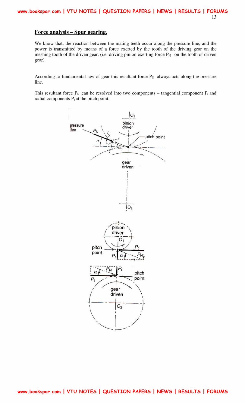
Force analysis – Spur gearing.
We know that, the reaction between the mating teeth occur along the pressure line, and the
power is transmitted by means of a force exerted by the tooth of the driving gear on the
meshing tooth of the driven gear. (i.e. driving pinion exerting force PN on the tooth of driven
gear).
According to fundamental law of gear this resultant force PN always acts along the pressure
line.
This resultant force PN, can be resolved into two components – tangential component Pt and
radial components Pr at the pitch point.
www.bookspar.com | VTU NOTES | QUESTION PAPERS | NEWS | RESULTS | FORUMS
www.bookspar.com | VTU NOTES | QUESTION PAPERS | NEWS | RESULTS | FORUMS
14
The tangential component Pt is a useful component (load) because it determines the magnitude
of the torque and consequently the power, which is transmitted.
The radial component Pr services no useful purpose (it is a separating force) and it is always
directed towards the centre of the gear.
The torque transmitted by the gear is given by
mNN
PM t −
×=
12
60
π
Where,
Mt = Torque transmitted gears (N- m)
PkW = Power transmitted by gears
N1 = Speed of rotation (rev / mn)
The tangential component Ft acts at the pitch circle radius.
∴ 2
dFM tt =
OR
d
MF t
t
2=
Where,
Mt = Torque transmitted gears N- mm
d = Pitch Circle diameter, mm
Further, we know,
Power transmitted by gears 60
2 tMNπ= ( kW)
Where
αtantr FF =
and
resultant force,
αCos
FFN t=
www.bookspar.com | VTU NOTES | QUESTION PAPERS | NEWS | RESULTS | FORUMS
www.bookspar.com | VTU NOTES | QUESTION PAPERS | NEWS | RESULTS | FORUMS
15
The above analysis of gear tooth force is based on the following assumptions.
i) As the point of contact moves the magnitude of resultant force PN changes. This
effect is neglected.
ii) It is assumed that only one pair of teeth takes the entire load. At times, there are
two pairs that are simultaneously in contact and share the load. This aspects is also
neglected.
iii) This analysis is valid under static conditions for example, when the gears are
running at very low velocities. In practice there are dynamic forces in addition to
force due to power transmission.
For gear tooth forces, It is always required to find out the magnitude and direction of two
components. The magnitudes are determined by using equations
12
60
N
PM t
π
×=
1
2
d
MF t
t =
Further, the direction of two components Ft and Fr are decided by constructing the free body
diagram.
?
How
Minimum Number of Teeth:
The minimum number of teeth on pinion to avoid interference is given by
α2min
sin
2=Z
For 20˚full depth involute system, it is always safe to assume the number of teeth as 18 or 20 Once the number of teeth on the pinion is decided, the number of teeth on the gear is
calculated by the velocity ratio 1
2
Z
Zi =
Face Width: In designing gears, it is required to express the face width in terms of module.
www.bookspar.com | VTU NOTES | QUESTION PAPERS | NEWS | RESULTS | FORUMS
www.bookspar.com | VTU NOTES | QUESTION PAPERS | NEWS | RESULTS | FORUMS
16
In practice, the optimum range of face width is mbm 5.125.9 ≤≤
Generally, face width is assumed as ten times module
∴
The LEWIS Bending Equation:
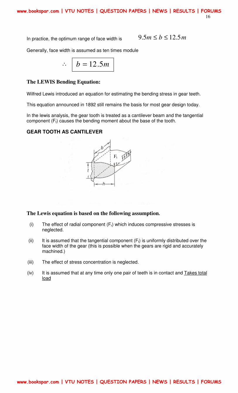
Wilfred Lewis introduced an equation for estimating the bending stress in gear teeth. This equation announced in 1892 still remains the basis for most gear design today. In the lewis analysis, the gear tooth is treated as a cantilever beam and the tangential component (Ft) causes the bending moment about the base of the tooth.
GEAR TOOTH AS CANTILEVER
The Lewis equation is based on the following assumption.
(i) The effect of radial component (Fr) which induces compressive stresses is neglected.
(ii) It is assumed that the tangential component (Ft) is uniformly distributed over the
face width of the gear (this is possible when the gears are rigid and accurately machined.)
(iii) The effect of stress concentration is neglected.
(iv) It is assumed that at any time only one pair of teeth is in contact and Takes total
load
mb 5.12=
Ft
www.bookspar.com | VTU NOTES | QUESTION PAPERS | NEWS | RESULTS | FORUMS
www.bookspar.com | VTU NOTES | QUESTION PAPERS | NEWS | RESULTS | FORUMS
17
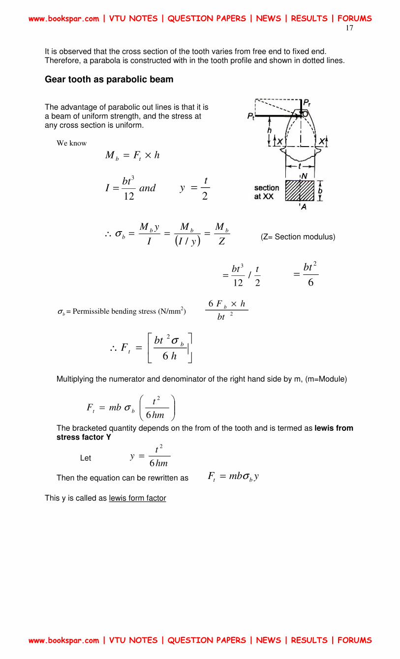
It is observed that the cross section of the tooth varies from free end to fixed end. Therefore, a parabola is constructed with in the tooth profile and shown in dotted lines.
Gear tooth as parabolic beam The advantage of parabolic out lines is that it is a beam of uniform strength, and the stress at any cross section is uniform.
We know
hFM tb ×=
andbt
I12
3
= 2
ty =
( ) Z
M
yI
M
I
yM bbbb ===∴
/σ (Z= Section modulus)
2
/12
3 tbt=
6
2bt
=
bσ = Permissible bending stress (N/mm2) 2
6
bt
hF b ×
=∴
h
btF b
t6
2σ
Multiplying the numerator and denominator of the right hand side by m, (m=Module)
=
hm
tmbF bt
6
2
σ
The bracketed quantity depends on the from of the tooth and is termed as lewis from stress factor Y
Let hm
ty
6
2
=
Then the equation can be rewritten as ymbF bt σ=
This y is called as lewis form factor
www.bookspar.com | VTU NOTES | QUESTION PAPERS | NEWS | RESULTS | FORUMS
www.bookspar.com | VTU NOTES | QUESTION PAPERS | NEWS | RESULTS | FORUMS
18
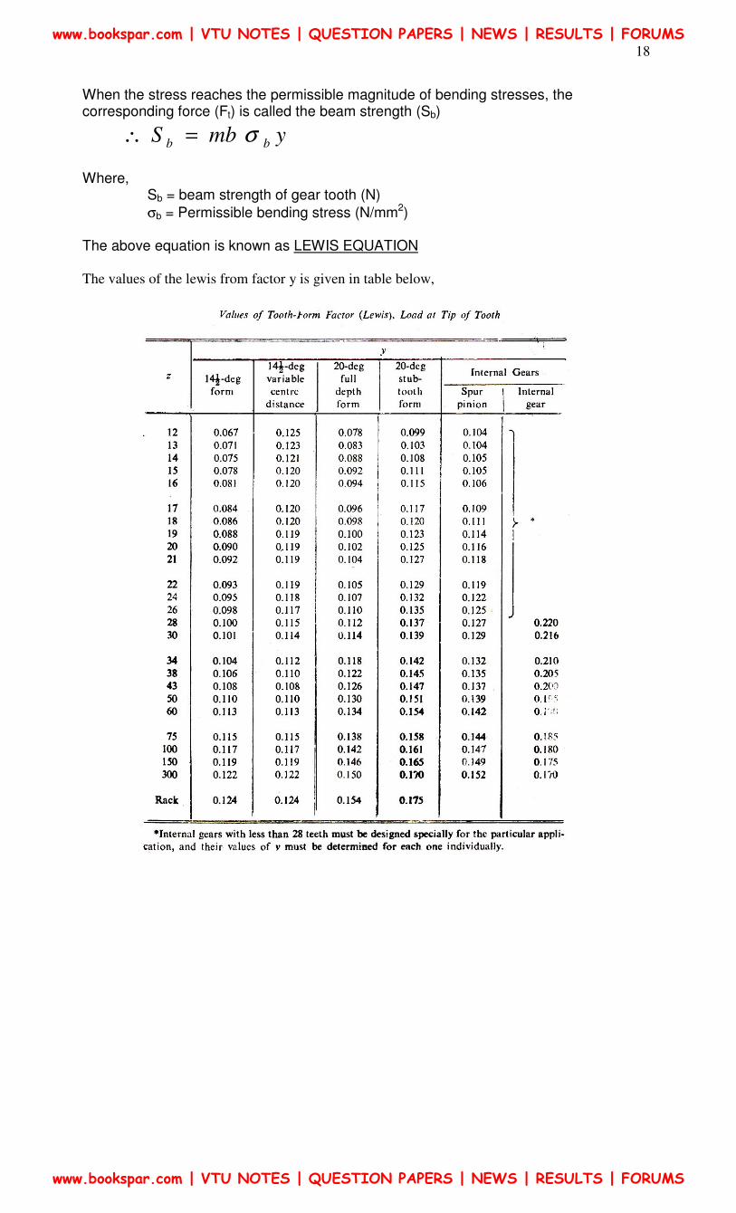
When the stress reaches the permissible magnitude of bending stresses, the corresponding force (Ft) is called the beam strength (Sb)
ymbS bb σ=∴
Where,
Sb = beam strength of gear tooth (N)
σb = Permissible bending stress (N/mm2) The above equation is known as LEWIS EQUATION
The values of the lewis from factor y is given in table below,
www.bookspar.com | VTU NOTES | QUESTION PAPERS | NEWS | RESULTS | FORUMS
www.bookspar.com | VTU NOTES | QUESTION PAPERS | NEWS | RESULTS | FORUMS
19
In order to avoid the breakage of gear tooth due to bending, the beam strength should be more
than the effective force between the meshing teeth
In design of gears, It is required to decide the weaker between pinion and gear.
When the same material is used for pinion and gear, the pinion is always weaker than the gear-----
--------- Why?
• We know that ymbS bb σ=
• It can be observed that ‘m’ and ‘b’ are same for pinion and as well as for gear in a gear
pair,
• When different materials are used, the product yb .σ decides the weaker between the
pinion and gear
• The lewis form factor y is always less for pinion compared to gear
• Therefore, when the same material is used for pinion and gear, the pinion is always
weaker than the gear.
Effective load-Calculation
Earlier we have seen how to determine the tangential component of the resultant force
between two meshing teeth.
This component can be calculated by using
I. 12
60
N
PM t
π
×=
And
II. 1
2
d
MF t
t =
The value of the tangential component, depends upon rated power and rated speed.
In gear design, the maximum force (due to maximum torque) is the criterion. This is
accounted by means of a factor called service factor – (Cs)
This service factor (Cs) is defined as
TorqueRated
TorqueMaximumCs =
www.bookspar.com | VTU NOTES | QUESTION PAPERS | NEWS | RESULTS | FORUMS
www.bookspar.com | VTU NOTES | QUESTION PAPERS | NEWS | RESULTS | FORUMS
20
( ) ( )
t
t
t
t
sF
F
M
MC maxmax ==∴
Where, (Ft) is the tangential force due to rated torque (Mt)
( ) tst FCF =max
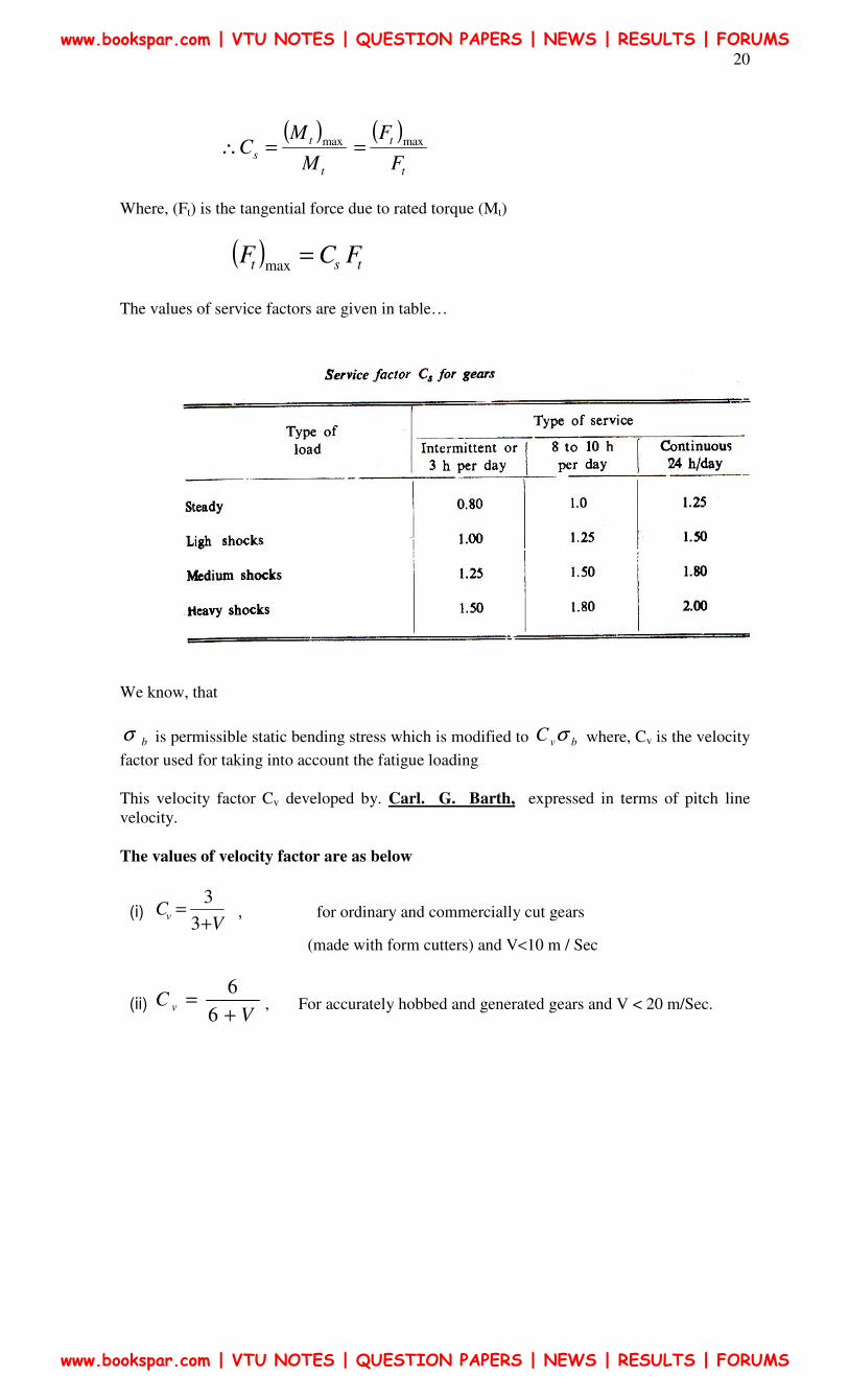
The values of service factors are given in table…
We know, that
bσ is permissible static bending stress which is modified to bvC σ where, Cv is the velocity
factor used for taking into account the fatigue loading
This velocity factor Cv developed by. Carl. G. Barth, expressed in terms of pitch line
velocity.
The values of velocity factor are as below
(i) V
Cv+
=3
3 , for ordinary and commercially cut gears
(made with form cutters) and V<10 m / Sec
(ii) V
C v+
=6
6, For accurately hobbed and generated gears and V < 20 m/Sec.
www.bookspar.com | VTU NOTES | QUESTION PAPERS | NEWS | RESULTS | FORUMS
www.bookspar.com | VTU NOTES | QUESTION PAPERS | NEWS | RESULTS | FORUMS
21
(iii) v
Cv+
=6.5
6.5 , For precision gears with shaving grinding and lapping and V > 20 m/Sec
Where, v = pitch line Velocity (m/Sec)
31060 ×=
dnπ d, mm
n, rev/min (The velocity factor is an empirical relationship developed by past experience).
Dynamic effects (Dynamic Tooth Load)
When gears rotate at very low speed, the transmitted load Pt can be considered to be the actual
force present between two meshing teeth
However in most of the cases the gears rotate at appreciable speed and it becomes necessary to
consider the dynamic force resulting from impact between mating teeth.
The Dynamic force is induced due to the following factors
1. Inaccuracies of the tooth profile
2. Errors in tooth spacings
3. Misalignment between bearings
4. Elasticity of parts, and
5. Inertia of rotating masses.
There are two methods to account for Dynamics load.
I. Approxinate estimation by the velocity factor in the preliminary stages of gear design
II. Precise estimation by Bucking Hams equation in the final stages of gear design.
Note: Approximate estimation, Using velocity factor (Cv) developed by Barth discussed earlier.
In the final stages of gear desing when gear dimensions are known errors specified and quality
of gears determined, the Dynamic load is calculated by equation derived by
Earle Buckingham
Where, Fd = Dynamic load
= Ft + Fi
Where, Ft = Tangential tooth load
Fi = Inevement load due to dynamic action
www.bookspar.com | VTU NOTES | QUESTION PAPERS | NEWS | RESULTS | FORUMS
www.bookspar.com | VTU NOTES | QUESTION PAPERS | NEWS | RESULTS | FORUMS
22
( )
t
ttd
FbVk
FCbVkFF
c ++
++=
3
3
Where,
V = Pitch line Velocity (m/Sec)
C = Dynamic factor (N/mm2) depending upon machining errors
e = measured error in action between gears in mm
b = face width of tooth (mm)
Ft = tangential force due to rated torque (N)
K3 = 20.67 in SI units
The Dynamic factor C, depends upon modulus of elasticity of materials for pinion and gear
and the form tooth or pressure angle and it is given by
+
=
21
1
11
EEK
eC
Where
K = Constant depending upon the form of tooth – (take from DDH)
E1 = Modulus of elasticity of pinion material (N/mm2)
E2 = Modulus of elasticity of gear material (N/mm2)
The Values of K, for various tooth forms are given as.
The error, e, in the dynamic load equation is measured error in action between gears in mm
This error depends upon the quality of gear and manufacturing methods.
www.bookspar.com | VTU NOTES | QUESTION PAPERS | NEWS | RESULTS | FORUMS
www.bookspar.com | VTU NOTES | QUESTION PAPERS | NEWS | RESULTS | FORUMS
23
WEAR TOOTH LOAD
WEAR:
For gears wear is defined as loss of material from contacting surfaces of teeth.
It is further classified as
• Normal wear
• Moderate wear
• Destructive wear
• Abrasive wear
• Scratching and etc.
Generally, normal wear (Polishinging in) does not constitute failure because it involves loss
of metal at a rate too slow to affect performance
• Moderate wear refers to loss of metal more rapid than normal wear.
• This need not necessarily be destructive and may develop on heavily loaded gear teeth.
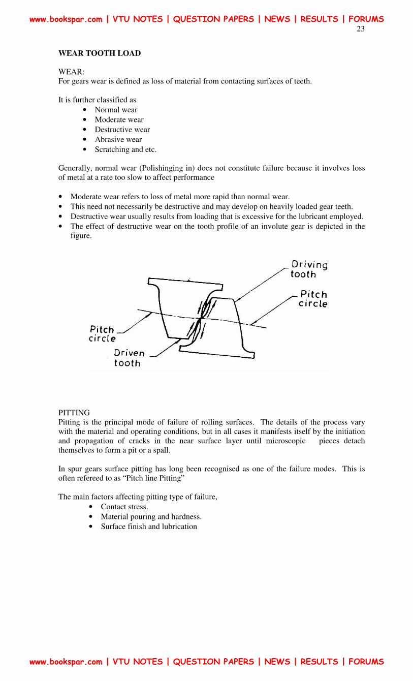
• Destructive wear usually results from loading that is excessive for the lubricant employed.
• The effect of destructive wear on the tooth profile of an involute gear is depicted in the
figure.
PITTING
Pitting is the principal mode of failure of rolling surfaces. The details of the process vary
with the material and operating conditions, but in all cases it manifests itself by the initiation
and propagation of cracks in the near surface layer until microscopic pieces detach
themselves to form a pit or a spall.
In spur gears surface pitting has long been recognised as one of the failure modes. This is
often refereed to as “Pitch line Pitting”
The main factors affecting pitting type of failure,
• Contact stress.
• Material pouring and hardness.
• Surface finish and lubrication
www.bookspar.com | VTU NOTES | QUESTION PAPERS | NEWS | RESULTS | FORUMS
www.bookspar.com | VTU NOTES | QUESTION PAPERS | NEWS | RESULTS | FORUMS
24
Contact stress was originally conceived By “HERTZ” (1896) in whose name it is often
referred to as Hertz Contact Stress.
The failure of the gear tooth due to pitting occurs when the contact stress between two
meshing teeth exceeds the surface endurance strength the material
In order to avoid this type of failure, the proportions of the gear tooth and surface properties
such as surface hardness should be selected in such a way that the wear strength of the gear
tooth is more than the effective load between the meshing teeth.
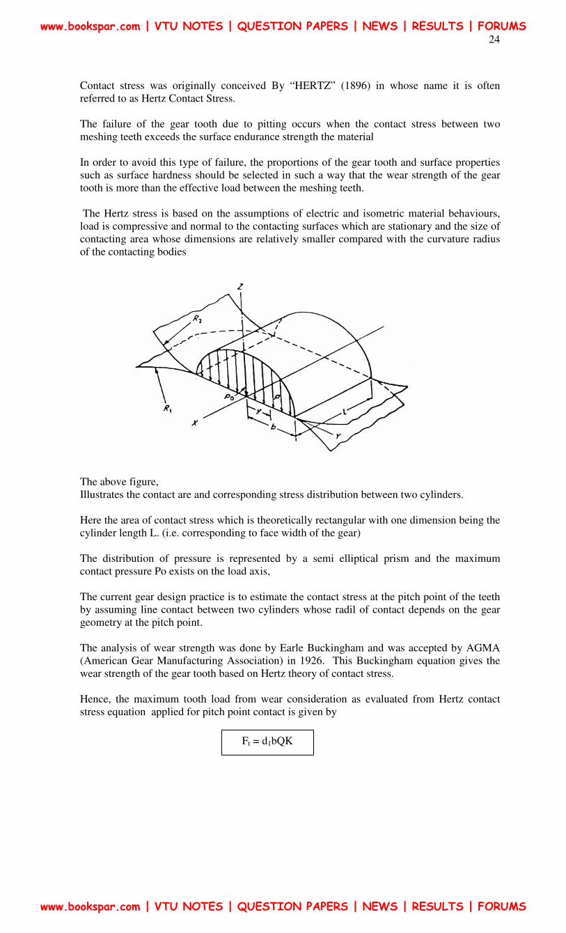
The Hertz stress is based on the assumptions of electric and isometric material behaviours,
load is compressive and normal to the contacting surfaces which are stationary and the size of
contacting area whose dimensions are relatively smaller compared with the curvature radius
of the contacting bodies
The above figure,
Illustrates the contact are and corresponding stress distribution between two cylinders.
Here the area of contact stress which is theoretically rectangular with one dimension being the
cylinder length L. (i.e. corresponding to face width of the gear)
The distribution of pressure is represented by a semi elliptical prism and the maximum
contact pressure Po exists on the load axis,
The current gear design practice is to estimate the contact stress at the pitch point of the teeth
by assuming line contact between two cylinders whose radil of contact depends on the gear
geometry at the pitch point.
The analysis of wear strength was done by Earle Buckingham and was accepted by AGMA
(American Gear Manufacturing Association) in 1926. This Buckingham equation gives the
wear strength of the gear tooth based on Hertz theory of contact stress.
Hence, the maximum tooth load from wear consideration as evaluated from Hertz contact
stress equation applied for pitch point contact is given by
Ft = d1bQK
www.bookspar.com | VTU NOTES | QUESTION PAPERS | NEWS | RESULTS | FORUMS
www.bookspar.com | VTU NOTES | QUESTION PAPERS | NEWS | RESULTS | FORUMS
25
Where,
d1 = Pitch circle diameter of pinion in mm.
b = Face width of the pinion in mm.
Q = Ratio factor 1
2
+=
VR
VR
12
22
ZZ
Z
+=
and
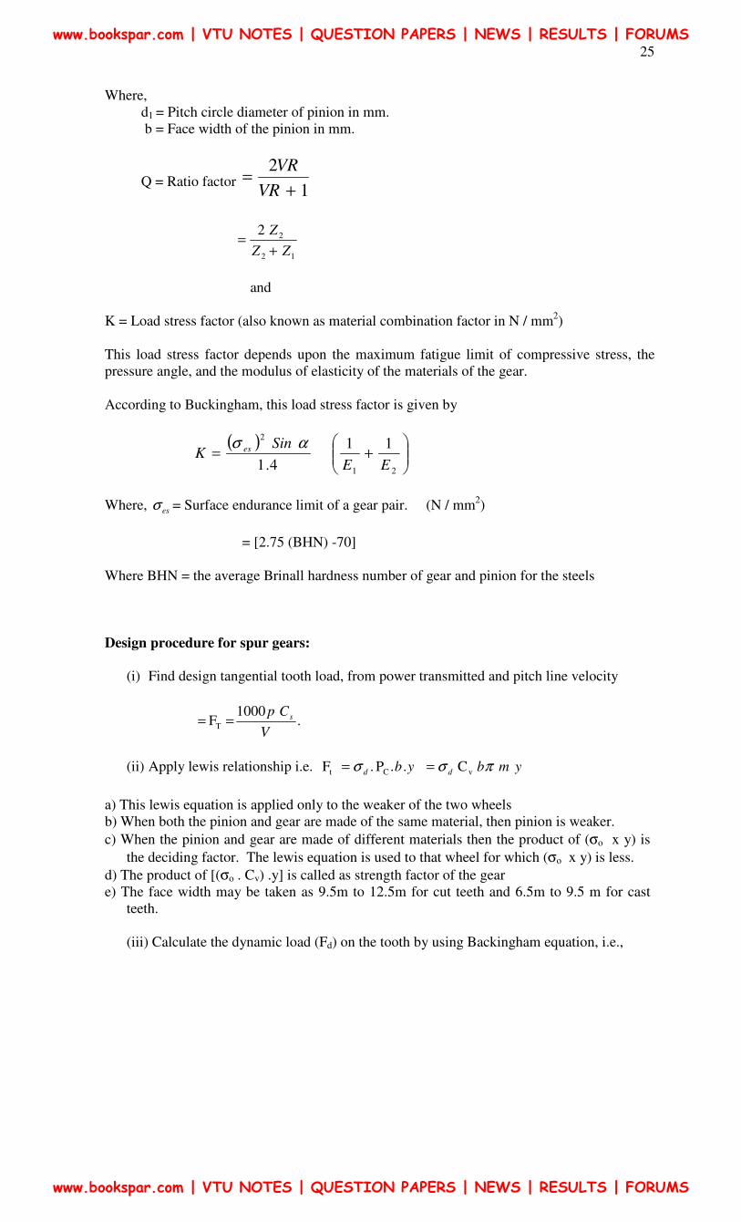
K = Load stress factor (also known as material combination factor in N / mm2)
This load stress factor depends upon the maximum fatigue limit of compressive stress, the
pressure angle, and the modulus of elasticity of the materials of the gear.
According to Buckingham, this load stress factor is given by
( )
+=
21
211
4.1 EE
SinK es ασ
Where, esσ = Surface endurance limit of a gear pair. (N / mm2)
= [2.75 (BHN) -70]
Where BHN = the average Brinall hardness number of gear and pinion for the steels
Design procedure for spur gears:
(i) Find design tangential tooth load, from power transmitted and pitch line velocity
.1000 F T
V
Cp s==
(ii) Apply lewis relationship i.e. ybd ..P .F Ct σ= ymbd πσ vC =
a) This lewis equation is applied only to the weaker of the two wheels
b) When both the pinion and gear are made of the same material, then pinion is weaker.
c) When the pinion and gear are made of different materials then the product of (σo x y) is
the deciding factor. The lewis equation is used to that wheel for which (σo x y) is less.
d) The product of [(σo . Cv) .y] is called as strength factor of the gear
e) The face width may be taken as 9.5m to 12.5m for cut teeth and 6.5m to 9.5 m for cast
teeth.
(iii) Calculate the dynamic load (Fd) on the tooth by using Backingham equation, i.e.,
www.bookspar.com | VTU NOTES | QUESTION PAPERS | NEWS | RESULTS | FORUMS
www.bookspar.com | VTU NOTES | QUESTION PAPERS | NEWS | RESULTS | FORUMS
26
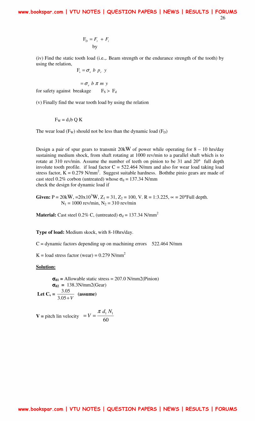
it FF +=DF
by
(iv) Find the static tooth load (i.e.,. Beam strength or the endurance strength of the tooth) by
using the relation,
ypb ceσ=sF
ymbe πσ=
for safety against breakage FS > Fd
(v) Finally find the wear tooth load by using the relation
FW = d1b Q K
The wear load (FW) should not be less than the dynamic load (FD)
Design a pair of spur gears to transmit 20kW of power while operating for 8 – 10 hrs/day
sustaining medium shock, from shaft rotating at 1000 rev/min to a parallel shaft which is to
rotate at 310 rev/min. Assume the number of teeth on pinion to be 31 and 20° full depth
involute tooth profile. if load factor C = 522.464 N/mm and also for wear load taking load
stress factor, K = 0.279 N/mm2. Suggest suitable hardness. Boththe pinio gears are made of
cast steel 0.2% corbon (untreated) whose σd = 137.34 N/mm
check the design for dynamic load if
Given: P = 20kW, =20x103W, Z1 = 31, Z2 = 100, V. R = 1:3.225, ∝ = 20°Full depth.
N1 = 1000 rev/min, N2 = 310 rev/min
Material: Cast steel 0.2% C, (untreated) σd = 137.34 N/mm2
Type of load: Medium skock, with 8-10hrs/day.
C = dynamic factors depending up on machining errors 522.464 N/mm
K = load stress factor (wear) = 0.279 N/mm2
Solution:
σσσσd1 = Allowable static stress = 207.0 N/mm2(Pinion)
σσσσd2 = 138.3N/mm2(Gear)
Let Cv = V+05.3
05.3 (assume)
V = pitch lin velocity 60
11 NdV
π==
www.bookspar.com | VTU NOTES | QUESTION PAPERS | NEWS | RESULTS | FORUMS
www.bookspar.com | VTU NOTES | QUESTION PAPERS | NEWS | RESULTS | FORUMS
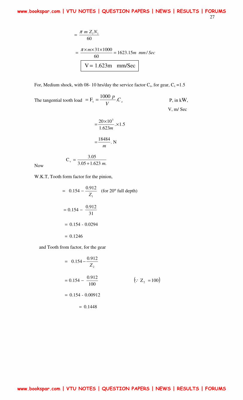
27
60
11NZmπ=
Secmmmm
/15.162360
100031 =
×××=
π
For, Medium shock, with 08- 10 hrs/day the service factor Cs, for gear, Cs =1.5
The tangential tooth load sCV
p.
1000 F t == P, in kW,
V, m/ Sec
5.1.623.1
1020
3
××
=m
N.18484
m=
Now .623.105.3
05.3C v
m+=
W.K.T, Tooth form factor for the pinion,
1
912.00.154
Z−= (for 20° full depth)
31
912.0 0.154 −=
0.0294-0.154 =
0.1246 =
and Tooth from factor, for the gear
2
912.0 0.154
Z−=
100
912.0 0.154 −= ( ) 100 Z2 =Q
0.00912-0.154 =
0.1448 =
mm/Sec 1.623m V =
www.bookspar.com | VTU NOTES | QUESTION PAPERS | NEWS | RESULTS | FORUMS
www.bookspar.com | VTU NOTES | QUESTION PAPERS | NEWS | RESULTS | FORUMS
28
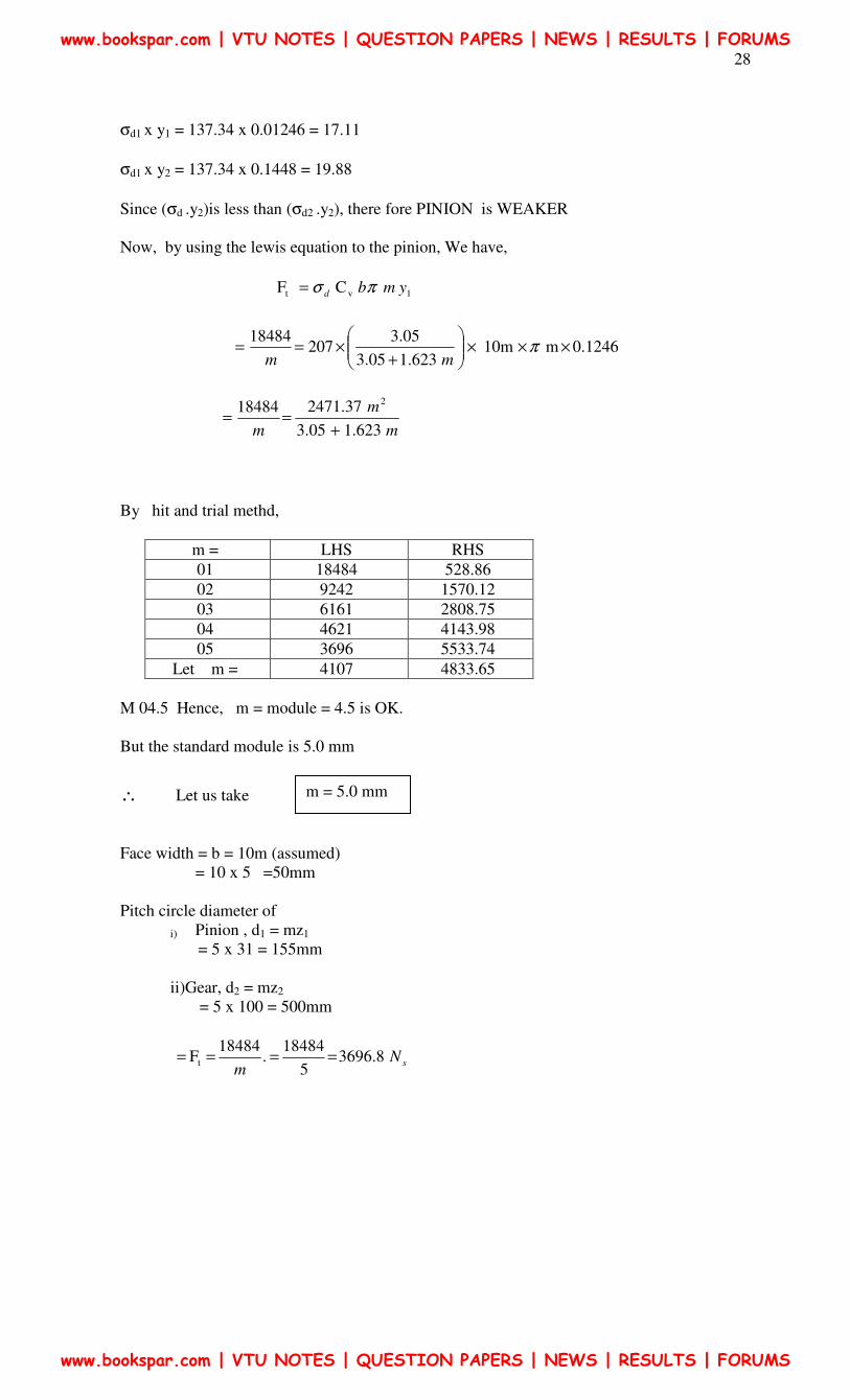
σd1 x y1 = 137.34 x 0.01246 = 17.11
σd1 x y2 = 137.34 x 0.1448 = 19.88
Since (σd .y2)is less than (σd2 .y2), there fore PINION is WEAKER
Now, by using the lewis equation to the pinion, We have,
1vt C F ymbd πσ=
0.1246m0m1 623.105.3
05.3207
18484×××
+×== π
mm
m
m
m 623.105.3
37.2471184842
+==
By hit and trial methd,
m = LHS RHS
01 18484 528.86
02 9242 1570.12
03 6161 2808.75
04 4621 4143.98
05 3696 5533.74
Let m = 4107 4833.65
M 04.5 Hence, m = module = 4.5 is OK.
But the standard module is 5.0 mm
∴ Let us take
Face width = b = 10m (assumed)
= 10 x 5 =50mm
Pitch circle diameter of
i) Pinion , d1 = mz1
= 5 x 31 = 155mm
ii)Gear, d2 = mz2
= 5 x 100 = 500mm
sNm
8.36965
18484.
18484 F t ====
m = 5.0 mm
www.bookspar.com | VTU NOTES | QUESTION PAPERS | NEWS | RESULTS | FORUMS
www.bookspar.com | VTU NOTES | QUESTION PAPERS | NEWS | RESULTS | FORUMS
29
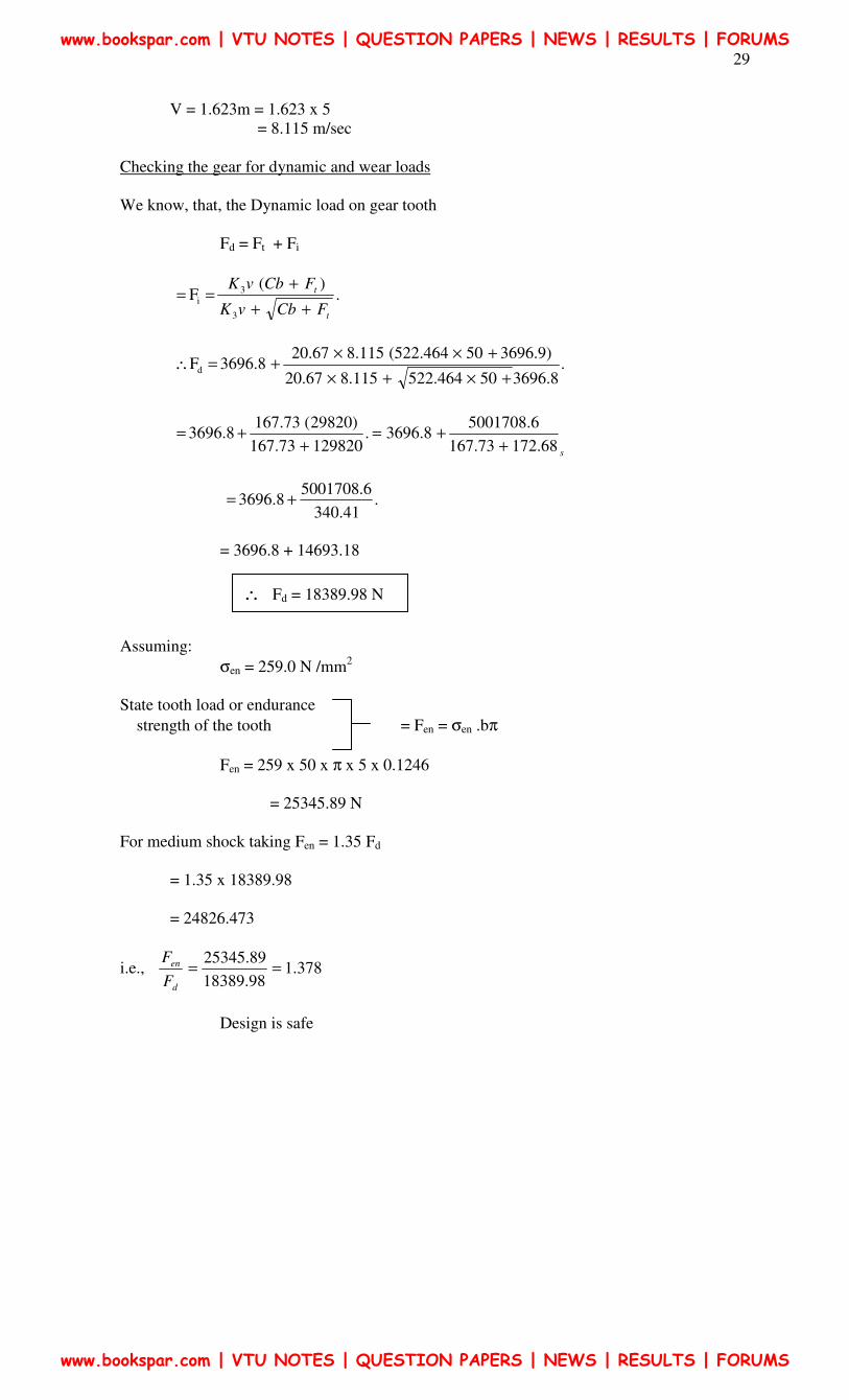
V = 1.623m = 1.623 x 5
= 8.115 m/sec
Checking the gear for dynamic and wear loads
We know, that, the Dynamic load on gear tooth
Fd = Ft + Fi
.)(
F 3
3
i
t
t
FCbvK
FCbvK
++
+==
.8.369650464.522115.867.20
)9.369650464.522(115.867.203696.8 F d
+×+×
+××+=∴
s68.17273.167
6.50017088.3696.
12982073.167
)29820(73.167 3696.8
++=
++=
.41.340
6.5001708 3696.8 +=
= 3696.8 + 14693.18
Assuming:
σen = 259.0 N /mm2
State tooth load or endurance
strength of the tooth = Fen = σen .bπ
Fen = 259 x 50 x π x 5 x 0.1246
= 25345.89 N
For medium shock taking Fen = 1.35 Fd
= 1.35 x 18389.98
= 24826.473
i.e., 378.198.18389
89.25345==
d
en
F
F
Design is safe
∴ Fd = 18389.98 N
www.bookspar.com | VTU NOTES | QUESTION PAPERS | NEWS | RESULTS | FORUMS
www.bookspar.com | VTU NOTES | QUESTION PAPERS | NEWS | RESULTS | FORUMS
30
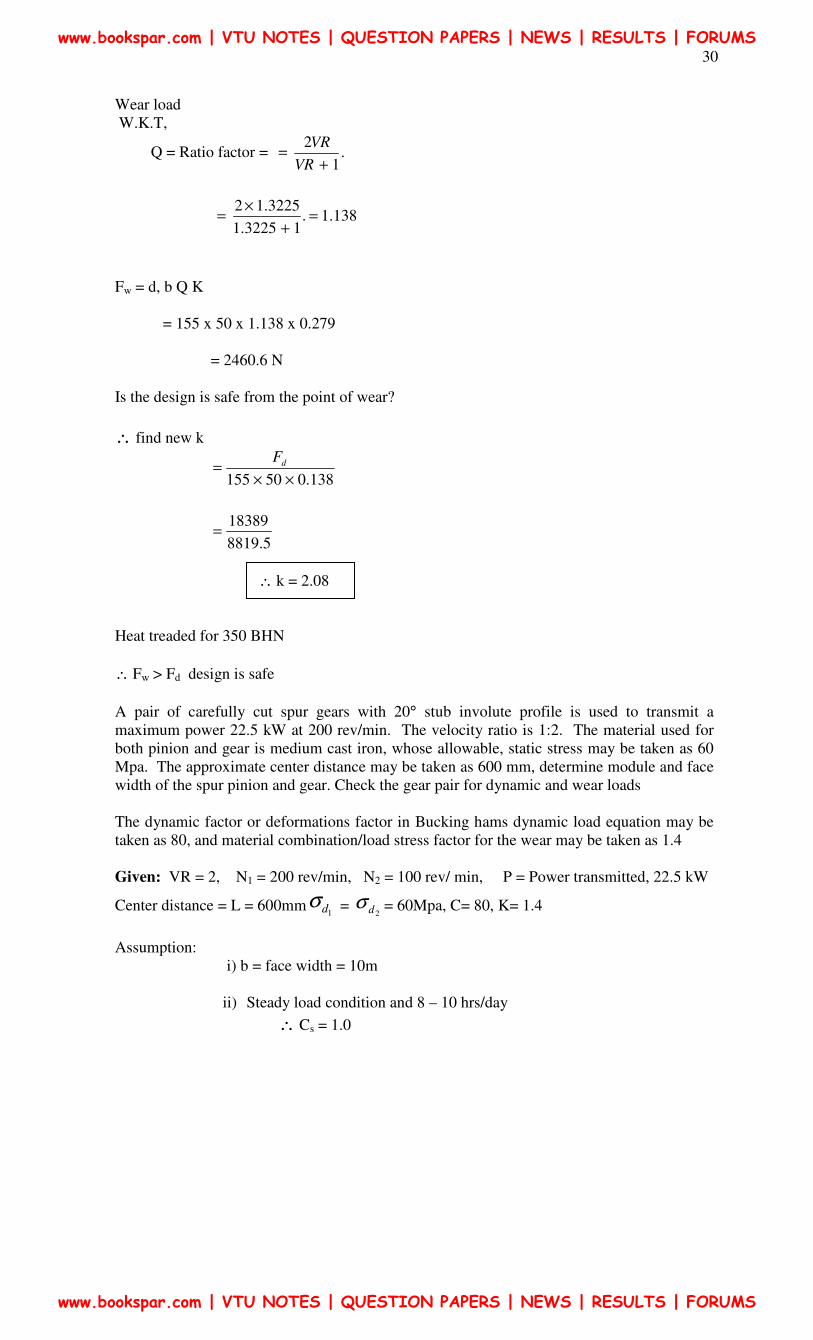
Wear load
W.K.T,
Q = Ratio factor = .1
2
+=
VR
VR
138.1.13225.1
3225.12 =
+
×=
Fw = d, b Q K
= 155 x 50 x 1.138 x 0.279
= 2460.6 N
Is the design is safe from the point of wear?
∴ find new k
138.050155 ××
= dF
5.8819
18389=
∴ k = 2.08
Heat treaded for 350 BHN
∴ Fw > Fd design is safe
A pair of carefully cut spur gears with 20° stub involute profile is used to transmit a
maximum power 22.5 kW at 200 rev/min. The velocity ratio is 1:2. The material used for
both pinion and gear is medium cast iron, whose allowable, static stress may be taken as 60
Mpa. The approximate center distance may be taken as 600 mm, determine module and face
width of the spur pinion and gear. Check the gear pair for dynamic and wear loads
The dynamic factor or deformations factor in Bucking hams dynamic load equation may be
taken as 80, and material combination/load stress factor for the wear may be taken as 1.4
Given: VR = 2, N1 = 200 rev/min, N2 = 100 rev/ min, P = Power transmitted, 22.5 kW
Center distance = L = 600mm1dσ =
2dσ = 60Mpa, C= 80, K= 1.4
Assumption:
i) b = face width = 10m
ii) Steady load condition and 8 – 10 hrs/day
∴ Cs = 1.0
www.bookspar.com | VTU NOTES | QUESTION PAPERS | NEWS | RESULTS | FORUMS
www.bookspar.com | VTU NOTES | QUESTION PAPERS | NEWS | RESULTS | FORUMS
31
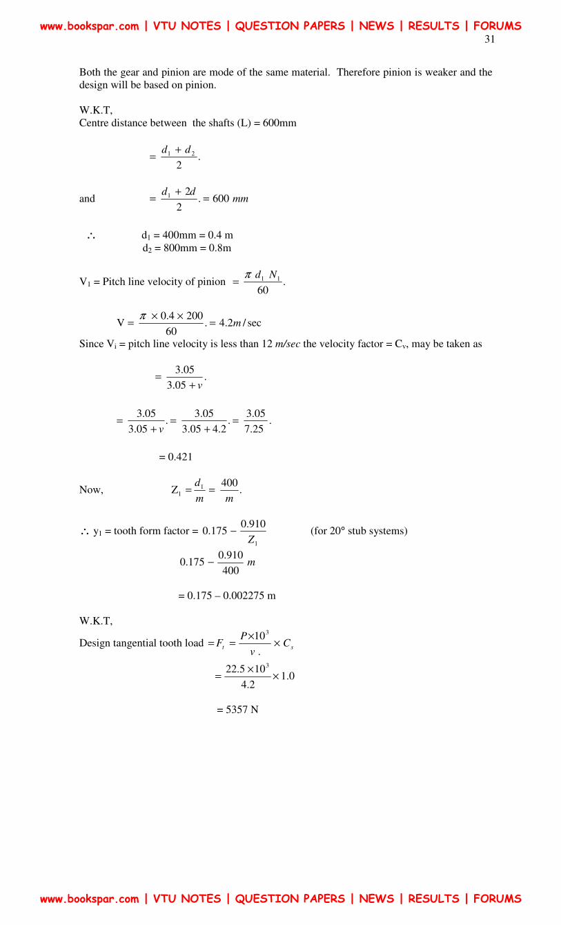
Both the gear and pinion are mode of the same material. Therefore pinion is weaker and the
design will be based on pinion.
W.K.T,
Centre distance between the shafts (L) = 600mm
.2
21 dd +=
and mmdd
600.2
2 1 =
+=
∴ d1 = 400mm = 0.4 m
d2 = 800mm = 0.8m
V1 = Pitch line velocity of pinion .60
11 Ndπ=
sec/2.4.60
2004.0 V m=
××=
π
Since Vi = pitch line velocity is less than 12 m/sec the velocity factor = Cv, may be taken as
.05.3
05.3
v+=
.25.7
05.3 .
2.405.3
05.3 .
05.3
05.3 =
+=
+=
v
= 0.421
Now, .400
Z 11
mm
d==
∴ y1 = tooth form factor = 1
910.0175.0
Z− (for 20° stub systems)
m400
910.0175.0 −
= 0.175 – 0.002275 m
W.K.T,
Design tangential tooth load st Cv
PF ×
×==
.
103
0.12.4
105.22 3
××
=
= 5357 N
www.bookspar.com | VTU NOTES | QUESTION PAPERS | NEWS | RESULTS | FORUMS
www.bookspar.com | VTU NOTES | QUESTION PAPERS | NEWS | RESULTS | FORUMS
32
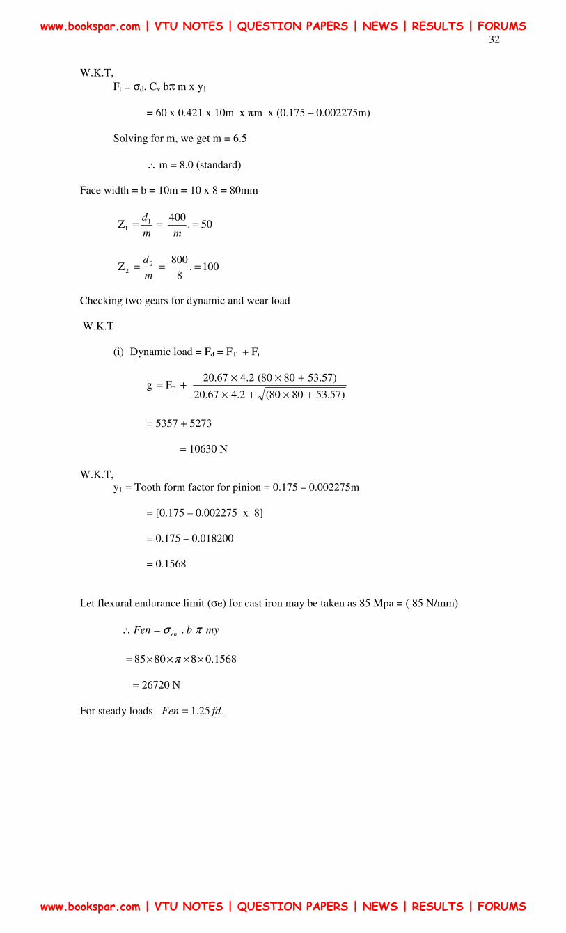
W.K.T,
Ft = σd. Cv bπ m x y1
= 60 x 0.421 x 10m x πm x (0.175 – 0.002275m)
Solving for m, we get m = 6.5
∴ m = 8.0 (standard)
Face width = b = 10m = 10 x 8 = 80mm
50.400
Z 11 ===
mm
d
100.8
800 Z 2
2 ===m
d
Checking two gears for dynamic and wear load
W.K.T
(i) Dynamic load = Fd = FT + Fi
g)57.538080(2.467.20
)57.538080(2.467.20 F T
+×+×
+××+=
= 5357 + 5273
= 10630 N
W.K.T,
y1 = Tooth form factor for pinion = 0.175 – 0.002275m
= [0.175 – 0.002275 x 8]
= 0.175 – 0.018200
= 0.1568
Let flexural endurance limit (σe) for cast iron may be taken as 85 Mpa = ( 85 N/mm)
mybFen en πσ ..=∴
= 26720 N
For steady loads .25.1 fdFen =
0.156888085 ××××= π
www.bookspar.com | VTU NOTES | QUESTION PAPERS | NEWS | RESULTS | FORUMS
www.bookspar.com | VTU NOTES | QUESTION PAPERS | NEWS | RESULTS | FORUMS
33
1061025.1 ×
N5.13287
W.K.T,
Q = Ratio factor 12
22
1
2
+
×=
+=
VR
VR
= 1.33
Fw = d1 b Q K
= 400 x 80 x 1.33 x 1.4 = 59584 N
Since both Fen and Fw are greater than Fd, the design is safe
www.bookspar.com | VTU NOTES | QUESTION PAPERS | NEWS | RESULTS | FORUMS
www.bookspar.com | VTU NOTES | QUESTION PAPERS | NEWS | RESULTS | FORUMS
34
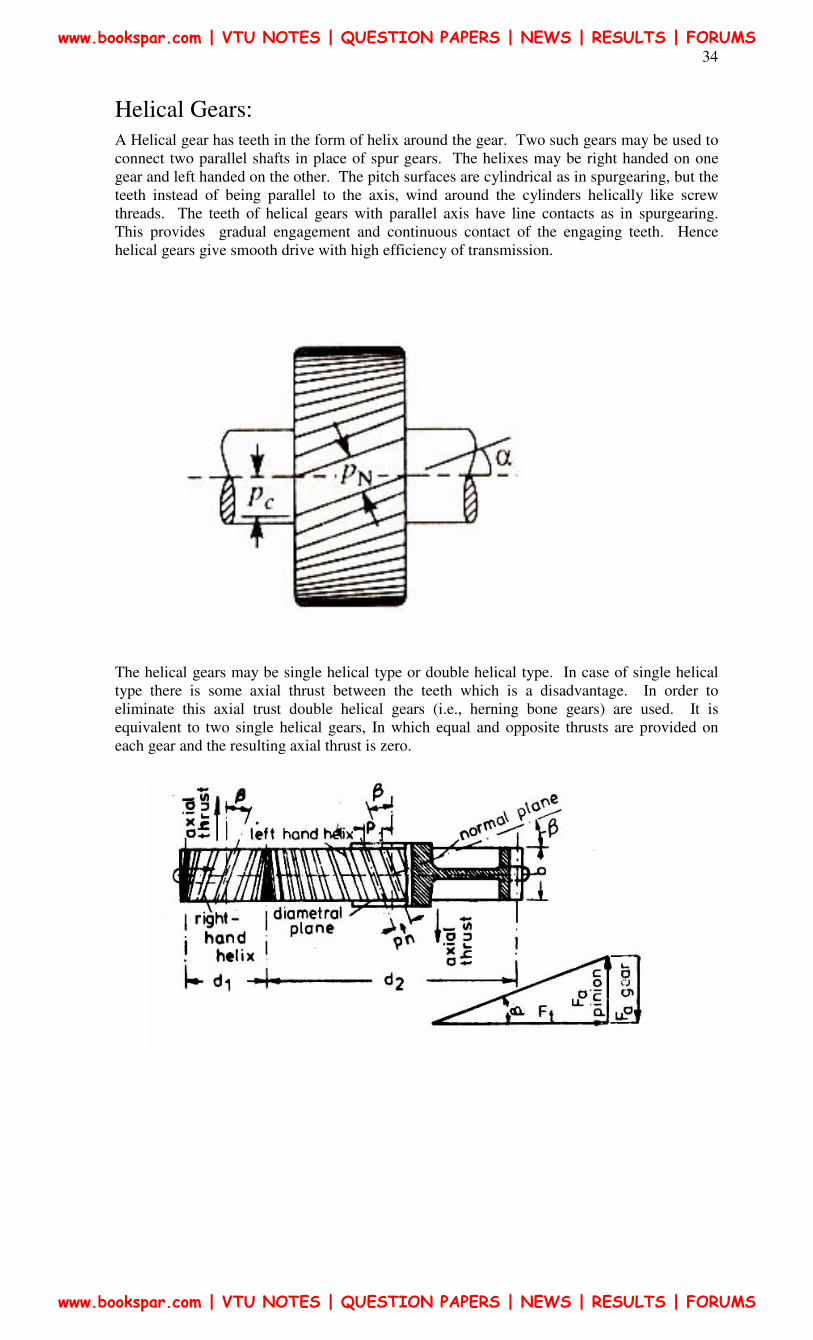
Helical Gears:
A Helical gear has teeth in the form of helix around the gear. Two such gears may be used to
connect two parallel shafts in place of spur gears. The helixes may be right handed on one
gear and left handed on the other. The pitch surfaces are cylindrical as in spurgearing, but the
teeth instead of being parallel to the axis, wind around the cylinders helically like screw
threads. The teeth of helical gears with parallel axis have line contacts as in spurgearing.
This provides gradual engagement and continuous contact of the engaging teeth. Hence
helical gears give smooth drive with high efficiency of transmission.
The helical gears may be single helical type or double helical type. In case of single helical
type there is some axial thrust between the teeth which is a disadvantage. In order to
eliminate this axial trust double helical gears (i.e., herning bone gears) are used. It is
equivalent to two single helical gears, In which equal and opposite thrusts are provided on
each gear and the resulting axial thrust is zero.
www.bookspar.com | VTU NOTES | QUESTION PAPERS | NEWS | RESULTS | FORUMS
www.bookspar.com | VTU NOTES | QUESTION PAPERS | NEWS | RESULTS | FORUMS
35
Terms used:
Helix angle: It is constant angle made by the helices with the axis of rotation
Axial pitch: It is the distance parallel to the axis between similar faces of adjacent teeth. It is
same as circular pitch and is therefore denoted by PC.
Normal pitch: It is the distance between similar faces of adjacent teeth along a helix on the
pitch cylinders normal to the teeth. It is denoted by PN.
PN = PC cos β again ∝N = Normal pressure angle
∝ = Pr. angle
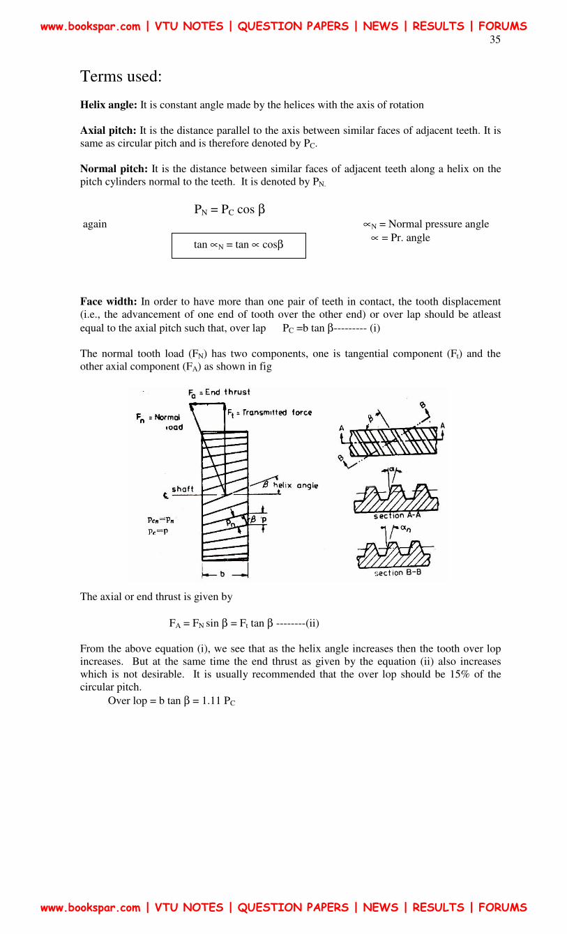
Face width: In order to have more than one pair of teeth in contact, the tooth displacement
(i.e., the advancement of one end of tooth over the other end) or over lap should be atleast
equal to the axial pitch such that, over lap PC =b tan β--------- (i)
The normal tooth load (FN) has two components, one is tangential component (Ft) and the
other axial component (FA) as shown in fig
The axial or end thrust is given by
FA = FN sin β = Ft tan β --------(ii)
From the above equation (i), we see that as the helix angle increases then the tooth over lop
increases. But at the same time the end thrust as given by the equation (ii) also increases
which is not desirable. It is usually recommended that the over lop should be 15% of the
circular pitch.
Over lop = b tan β = 1.11 PC
tan ∝N = tan ∝ cosβ
www.bookspar.com | VTU NOTES | QUESTION PAPERS | NEWS | RESULTS | FORUMS
www.bookspar.com | VTU NOTES | QUESTION PAPERS | NEWS | RESULTS | FORUMS
36
∴βtan
11.1 cPb = ( )mcp ªπ==Q b = minimum face width
m = Module,
Note:
1. The maximum face width may be taken as 12.5 to 20.0m
2. In case of double helical or herring bone gears the minimum face width is given by
βtan
3.2 cPb = =
β
π
tan
3.2 mb
×=
β
π
sin
3.2 m×=≥
3. In a single helical gears, the helix angle ranges from 20° to 35°, while for double
helical gears it may be made up to 45°
b = 12.5 mn To 20.mn.
Formative or equivalent number of teeth for helical gear:
The formative or equivalent number of teeth for a helical gear may be defined as the number
of teeth that can be generated on the surface of a cylinder having a radius equal to the radius
of curvature at a point at the tip of the minor axis of an ellipse obtained by taking a section of
the gear in the normal plane. Mathematically, formative or equivalent number of teeth an a
helical gear
ZE = Z / cos3. β
Z = Actual number of teeth on a helical gear and
β = helix angle.
Proportion of Helical Gears: AGMA Recommendations.
Pressure angle in the plane of rotation ∝ = 15° to 25°
Helix angle, β = 20 - 45°
Addendum = 0.8 m (maximum)
Dedendum = 1.0 m
Minimum total depth = 1.8 m (maximum)
Minimum clearance = 0.2 m
Thickness of tooth = 1.5708 m
STRENGTH OF HELICAL GEARS: (P962 K/G)
In helical gears, the contact between mating teeth is gradual, starting at one end and moving
along the teeth so that at any instant the line of contact runs diagonally across the teeth.
Therefore, in order to find the strength of helical gear, a modified lewis equation is used.
It is given by, FT = σo. CV b π m y’.
Where
(i) FT, σo, CV, b, π, m, as usual , with same meanings,
www.bookspar.com | VTU NOTES | QUESTION PAPERS | NEWS | RESULTS | FORUMS
www.bookspar.com | VTU NOTES | QUESTION PAPERS | NEWS | RESULTS | FORUMS
37
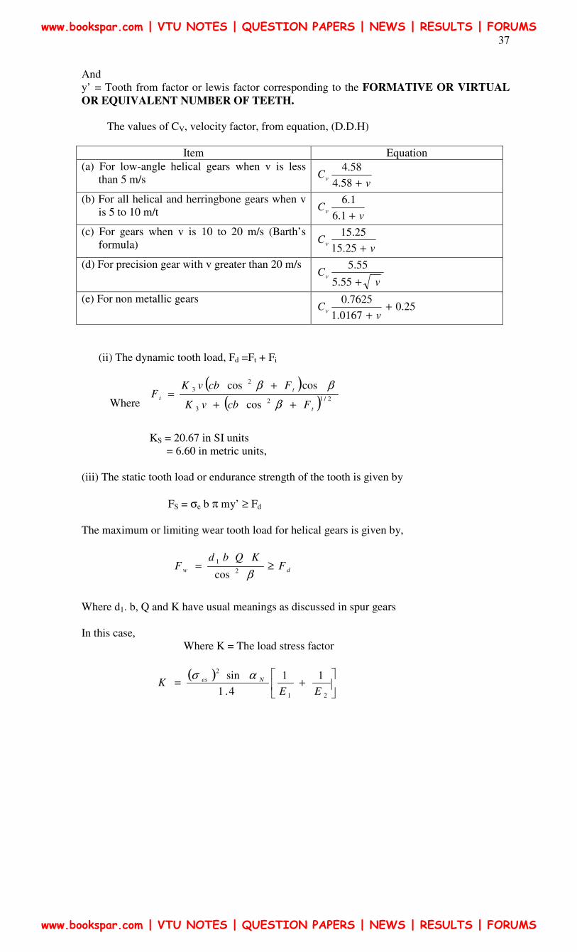
And
y’ = Tooth from factor or lewis factor corresponding to the FORMATIVE OR VIRTUAL
OR EQUIVALENT NUMBER OF TEETH.
The values of CV, velocity factor, from equation, (D.D.H)
Item Equation
(a) For low-angle helical gears when v is less
than 5 m/s vCv
+58.4
58.4
(b) For all helical and herringbone gears when v
is 5 to 10 m/t vCv
+1.6
1.6
(c) For gears when v is 10 to 20 m/s (Barth’s
formula) vCv
+25.15
25.15
(d) For precision gear with v greater than 20 m/s
vCv
+55.5
55.5
(e) For non metallic gears 25.0
0167.1
7625.0+
+ vCv
(ii) The dynamic tooth load, Fd =Ft + Fi
Where
( )( ) 2/12
3
2
3
cos
coscos
t
t
i
FcbvK
FcbvKF
++
+=
β
ββ
KS = 20.67 in SI units
= 6.60 in metric units,
(iii) The static tooth load or endurance strength of the tooth is given by
FS = σe b π my’ ≥ Fd
The maximum or limiting wear tooth load for helical gears is given by,
dw FKQbd
F ≥=β2
1
cos
Where d1. b, Q and K have usual meanings as discussed in spur gears
In this case,
Where K = The load stress factor
( )
+=
21
211
4.1
sin
EEK Nes ασ
www.bookspar.com | VTU NOTES | QUESTION PAPERS | NEWS | RESULTS | FORUMS
www.bookspar.com | VTU NOTES | QUESTION PAPERS | NEWS | RESULTS | FORUMS
38
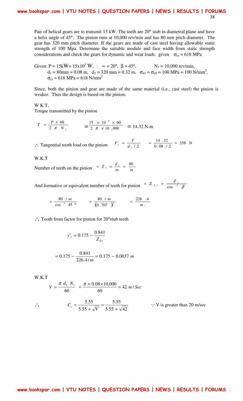
Pair of helical gears are to transmit 15 kW. The teeth are 20° stub in diametral plane and have
a helix angle of 45°. The pinion runs at 10,000 rev/min and has 80 mm pitch diameter. The
gear has 320 mm pitch diameter. If the gears are made of cast steel having allowable static
strength of 100 Mpa. Determine the suitable module and face width from static strength
considerations and check the gears for dynamic and wear loads. given σes = 618 MPa
Given: P = 15kW= 15x103 W, ∝ = 20°, β = 45°, N1 = 10,000 rev/min,
d1 = 80mm = 0.08 m, d2 = 320 mm = 0.32 m, σd1 = σd2 = 100 MPa = 100 N/mm2,
σes = 618 MPa = 618 N/mm2
Since, both the pinion and gear are made of the same material (i.e., cast steel) the pinion is
weaker. Thus the design is based on the pinion.
W K T,
Torque transmitted by the pinion
12
60
N
PT
π
×= = 000,102
601015 3
×
××
π = 14.32 N-m
∴ Tangential tooth load on the pinion N3582/08.0
32.14
2/1
===d
TF t
W.K.T
Number of teeth on the pinion mm
dZ
8011 ===
And formative or equivalent number of teeth for pinion β3
11
cos
ZZ E ==
( ) .
4.226
707.0
/80
45cos
/8033 m
mm==
°=
∴ Tooth from factor for pinion for 20°stub teeth
1
1
841.0175.0'
EZy −=
mm
0037.0175.0/4.226
841.0175.0 −=−=
W.K.T
60
11 NdV
π= Secm /42
60
000,1008.0=
××=
π
∴ 4255.5
55.5
55.5
55.5
+=
+=
VCv Q V is greater than 20 m/sec
www.bookspar.com | VTU NOTES | QUESTION PAPERS | NEWS | RESULTS | FORUMS
www.bookspar.com | VTU NOTES | QUESTION PAPERS | NEWS | RESULTS | FORUMS
39
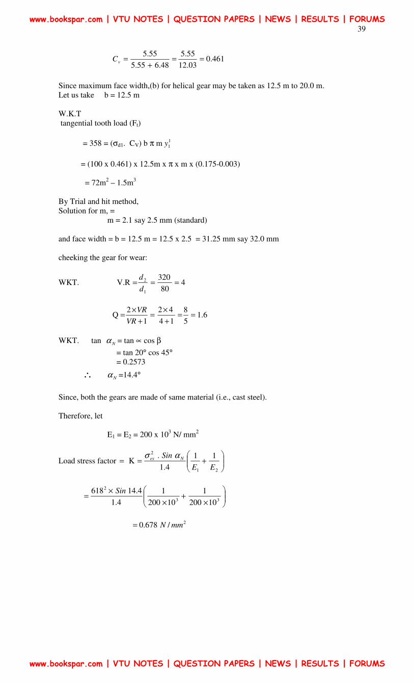
461.003.12
55.5
48.655.5
55.5==
+=vC
Since maximum face width,(b) for helical gear may be taken as 12.5 m to 20.0 m.
Let us take b = 12.5 m
W.K.T
tangential tooth load (Ft)
= 358 = (σd1. CV) b π m 1
1y
= (100 x 0.461) x 12.5m x π x m x (0.175-0.003)
= 72m2 – 1.5m
3
By Trial and hit method,
Solution for m, =
m = 2.1 say 2.5 mm (standard)
and face width = b = 12.5 m = 12.5 x 2.5 = 31.25 mm say 32.0 mm
cheeking the gear for wear:
WKT. 480
320V.R
1
2 ===d
d
6.15
8
14
42
1
2Q ==
+
×=
+
×=
VR
VR
WKT. tan Nα = tan ∝ cos β
= tan 20° cos 45°
= 0.2573
∴ Nα =14.4°
Since, both the gears are made of same material (i.e., cast steel).
Therefore, let
E1 = E2 = 200 x 103 N/ mm
2
Load stress factor
+==
21
211
4.1
.K
EE
Sin Nes ασ
×+
×
×=
33
2
10200
1
10200
1
4.1
4.14618 Sin
2/678.0 mmN=
www.bookspar.com | VTU NOTES | QUESTION PAPERS | NEWS | RESULTS | FORUMS
www.bookspar.com | VTU NOTES | QUESTION PAPERS | NEWS | RESULTS | FORUMS
40
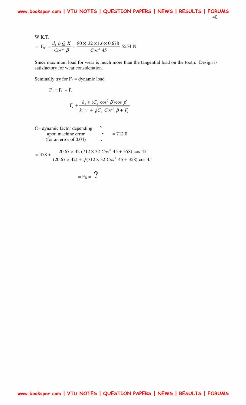
W.K.T,
N555445
678.06.13280F
22
1
CosCos
KQbdW
×××===
β
Since maximum load for wear is much more than the tangential load on the tooth. Design is
satisfactory for wear consideration.
Seminally try for Fd = dynamic load
Fd = Ft + Fi
tb
b
t
FCosCvk
Cvk
+++=
β
ββ2
3
2
3 cos)cos(F
C= dynamic factor depending
upon machine error = 712.0
(for an error of 0.04)
45cos)3584532712()4267.20(
45cos)3584532712(4267.20358
2
2
+×+×
+××+=
Cos
Cos
= FD = ?
www.bookspar.com | VTU NOTES | QUESTION PAPERS | NEWS | RESULTS | FORUMS
www.bookspar.com | VTU NOTES | QUESTION PAPERS | NEWS | RESULTS | FORUMS
41
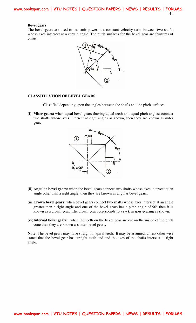
Bevel gears:
The bevel gears are used to transmit power at a constant velocity ratio between two shafts
whose axes intersect at a certain angle. The pitch surfaces for the bevel gear are frustums of
cones.
CLASSIFICATION OF BEVEL GEARS:
Classified depending upon the angles between the shafts and the pitch surfaces.
(i) Miter gears: when equal bevel gears (having equal teeth and equal pitch angles) connect
two shafts whose axes intersect at right angles as shown, then they are known as miter
gear.
(ii) Angular bevel gears: when the bevel gears connect two shafts whose axes intersect at an
angle other than a right angle, then they are known as angular bevel gears.
(iii)Crown bevel gears: when bevel gears connect two shafts whose axes intersect at an angle
greater than a right angle and one of the bevel gears has a pitch angle of 90° then it is
known as a crown gear. The crown gear corresponds to a rack in spur gearing as shown.
(iv) Internal bevel gears: when the teeth on the bevel gear are cut on the inside of the pitch
cone then they are known ass inter bevel gears.
Note: The bevel gears may have straight or spiral teeth. It may be assumed, unless other wise
stated that the bevel gear has straight teeth and and the axes of the shafts intersect at right
angle.
www.bookspar.com | VTU NOTES | QUESTION PAPERS | NEWS | RESULTS | FORUMS
www.bookspar.com | VTU NOTES | QUESTION PAPERS | NEWS | RESULTS | FORUMS
42
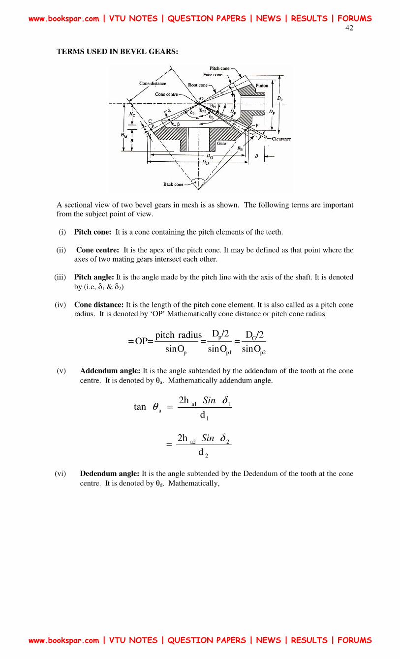
TERMS USED IN BEVEL GEARS:
A sectional view of two bevel gears in mesh is as shown. The following terms are important
from the subject point of view.
(i) Pitch cone: It is a cone containing the pitch elements of the teeth.
(ii) Cone centre: It is the apex of the pitch cone. It may be defined as that point where the
axes of two mating gears intersect each other.
(iii) Pitch angle: It is the angle made by the pitch line with the axis of the shaft. It is denoted
by (i.e, δ1 & δ2)
(iv) Cone distance: It is the length of the pitch cone element. It is also called as a pitch cone
radius. It is denoted by ‘OP’ Mathematically cone distance or pitch cone radius
p2
G
p1
p
p Osin
/2D
Osin
/2D
Osin
radiuspitchOP ====
(v) Addendum angle: It is the angle subtended by the addendum of the tooth at the cone
centre. It is denoted by θa. Mathematically addendum angle.
1
1a1a
d
2htan
δθ
Sin=
2
2a2
d
2h δSin=
(vi) Dedendum angle: It is the angle subtended by the Dedendum of the tooth at the cone
centre. It is denoted by θd. Mathematically,
www.bookspar.com | VTU NOTES | QUESTION PAPERS | NEWS | RESULTS | FORUMS
www.bookspar.com | VTU NOTES | QUESTION PAPERS | NEWS | RESULTS | FORUMS
43
1
11 sin2tan
d
h f
d
δθ =
2
22 sin2
d
h f δ=
Where, ha1, ha2 = addendum of the pinion and gear respectively, mm
hf1, hf2 = dedendum of pinion and gear respectively, mm
(vii) Face angle: It is the angle subtended by the face of the tooth at the cone centre. The
face angle is equal to the pitch angle plus addendum angle.
(viii) Root angle: It is the angle subtended by the root of the tooth at the cone centre. It is
equal to the pitch angle minus dedendum angle
(ix) Back cone: (Normal cone): It is the imaginary cone perpendicular to the pitch cone at
the end of the tooth.
(x) Crown height: It is the distance of the crown point C, from the cone centre O,
parallel to the axis of the gear. It is the denoted by C
(xi) Mounting height: It is the distance of the back of the boss from the cone centre. It is
denoted by ‘ m’
(xii) Pitch diameter: It is the diameter of the largest pitch circle.
(xiii) Outside or addendum cone diameter: It is the maximum diameter of the teeth of the
gear. It is equal to the diameter of the blank from which the gear can be cut.
Mathematically outside dia ,
dO1 = d1 + 2ha1, Cos δ1
dO2 = d2 + 2ha2, Cos δ2
Proportions of Bevel gears:
The proportion for the bevel gear may be taken as
(i) Addendum: a = 1.0 m
(ii) Dedendum: d=1.2 m
(iii) Clearance = 0.2 m
(iv) Working depth = 2.0m
(v) Tooth thiknes = 1.5708
Formative or Equivalent number of teeth for Bevel Gears: (Tredgold’s approximation)
Ze = Z/Cosδ
www.bookspar.com | VTU NOTES | QUESTION PAPERS | NEWS | RESULTS | FORUMS
www.bookspar.com | VTU NOTES | QUESTION PAPERS | NEWS | RESULTS | FORUMS
44
STRENGTH OF BEVEL GEARS:
The strength of a bevel gear tooth is obtained in a similar way as discussed in the previous
articles. The modified form of the lewis equation for the tangential tooth load is given as
follows
−×==
L
bLdt
1
v ymb)C(F πσ
y1= lewis form factor based on formative or equivalent number of teeth
L = Slant height of pitch cone (or cone distance)
2
2
2
12
1dd +=
Where d1 and d2 are the pitch circle diameters on the larger diameter of pinion
and gears respectively
(i) The factor i.e, L
bL − may be called as bevel factor
(ii) For satisfactory operation of bevel gears the face width should be from 6m to 10
m. Also ratio L/b should not exceed 3, (i.e., b ≤ L / 3)for this the number of teeth
in the pinion must not be less than 2)(1
48
vR+
(iii) The dynamic loads for bevel gears may be obtained in the same similar manner as
discussed for spur gears.
(iv) The static tooth load or endurance strength of the tooth for bevel gears is given by
−==
L
bLee
1ymbF πσ
The value of flexural endurance limit (σe) may be taken from table
(v) The maximum or limiting load for wear for bevel gears is given by
1
1FδCos
kQbD ew ==
Where,
D1, b, Q, k, have usual meanings as discussed in spur gears except that Qe is based on
formative or equivalent number of teeth, such that,
12
22Q
ZeZe
Ze
+=
www.bookspar.com | VTU NOTES | QUESTION PAPERS | NEWS | RESULTS | FORUMS
www.bookspar.com | VTU NOTES | QUESTION PAPERS | NEWS | RESULTS | FORUMS
45
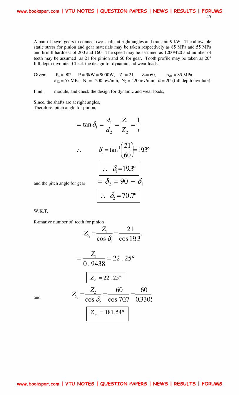
A pair of bevel gears to connect two shafts at right angles and transmit 9 kW. The allowable
static stress for pinion and gear materials may be taken respectively as 85 MPa and 55 MPa
and brinill hardness of 200 and 160. The speed may be assumed as 1200/420 and number of
teeth may be assumed as 21 for pinion and 60 for gear. Tooth profile may be taken as 20°
full depth involute. Check the design for dynamic and wear loads.
Given: θs = 90°, P = 9kW = 9000W, Z1 = 21, Z2= 60, σd1 = 85 MPa,
σd2 = 55 MPa, N1 = 1200 rev/min, N2 = 420 rev/min, α = 20°(full depth involute)
Find, module, and check the design for dynamic and wear loads,
Since, the shafts are at right angles,
Therefore, pitch angle for pinion,
iZ
Z
d
d 1tan
2
1
2
11 ==== δ
°=
=∴ − 3.19
60
21tan 1
1δ
and the pitch angle for gear 12 90 δδ −==
W.K.T,
formative number of teeth for pinion
.
3.19cos
21
cos 1
1
1==
δ
ZZe
°== 25.229438.0
1Z
and 3305.0
60
7.70cos
60
cos 2
2
2===
δ
ZZe
°=∴ 3.191δ
°=∴ 7.702δ
°= 25.221eZ
°= 54.1812eZ
www.bookspar.com | VTU NOTES | QUESTION PAPERS | NEWS | RESULTS | FORUMS
www.bookspar.com | VTU NOTES | QUESTION PAPERS | NEWS | RESULTS | FORUMS
46
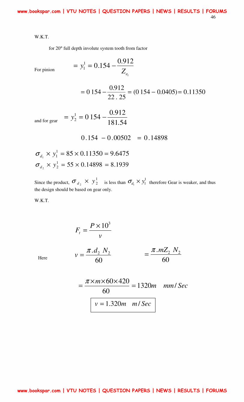
W.K.T.
for 20° full depth involute system tooth from factor
For pinion 1
912.0154.0
1
1
eZy −==
11350.0)0405.01540(
25.22
912.01540 =−=−=
and for gear 54.181
912.01540
1
2 −== y
14898.000502.0154.0 =−
6475.911350.0851
11=×=× ydσ
1939.814898.0551
22=×=× ydσ
Since the product, 1
22yd ×σ is less than
1
11yd ×σ therefore Gear is weaker, and thus
the design should be based on gear only.
W.K.T.
v
PFt
310×=
Here 60
. 22 Ndv
π=
60
. 22 NmZπ=
Secmmmm
/132060
42060=
×××=
π
Secmmv /320.1=
www.bookspar.com | VTU NOTES | QUESTION PAPERS | NEWS | RESULTS | FORUMS
www.bookspar.com | VTU NOTES | QUESTION PAPERS | NEWS | RESULTS | FORUMS
47
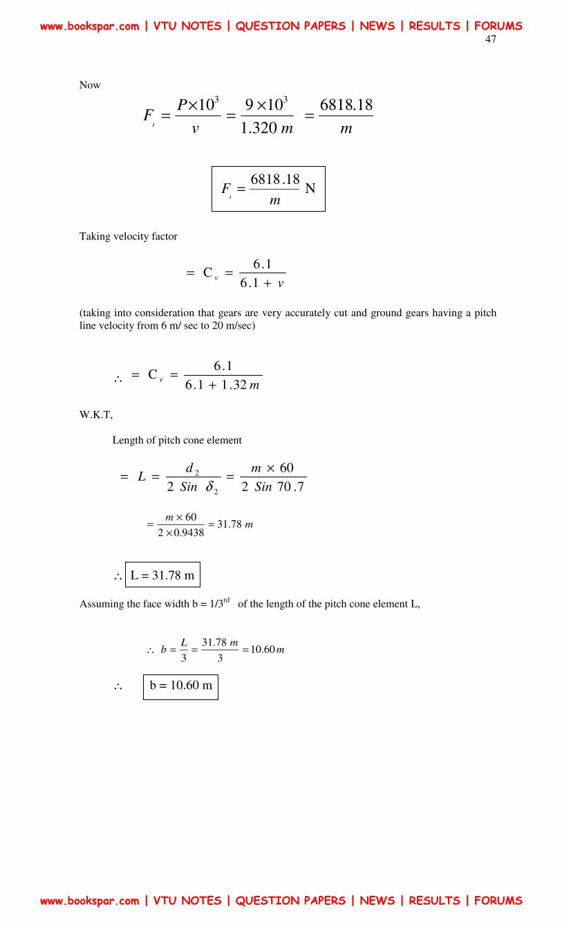
Now
mmv
PF
t
18.6818
320.1
1091033
=×
=×
=
Taking velocity factor
v
v+
==1.6
1.6C
(taking into consideration that gears are very accurately cut and ground gears having a pitch
line velocity from 6 m/ sec to 20 m/sec)
∴m
v32.11.6
1.6C
+==
W.K.T,
Length of pitch cone element
7.702
60
2 2
2
Sin
m
Sin
dL
×===
δ
mm
78.319438.02
60=
×
×=
∴ L = 31.78 m
Assuming the face width b = 1/3
rd of the length of the pitch cone element L,
mmL
b 60.103
78.31
3===∴
∴ b = 10.60 m
N18.6818
mF
t=
www.bookspar.com | VTU NOTES | QUESTION PAPERS | NEWS | RESULTS | FORUMS
www.bookspar.com | VTU NOTES | QUESTION PAPERS | NEWS | RESULTS | FORUMS
48
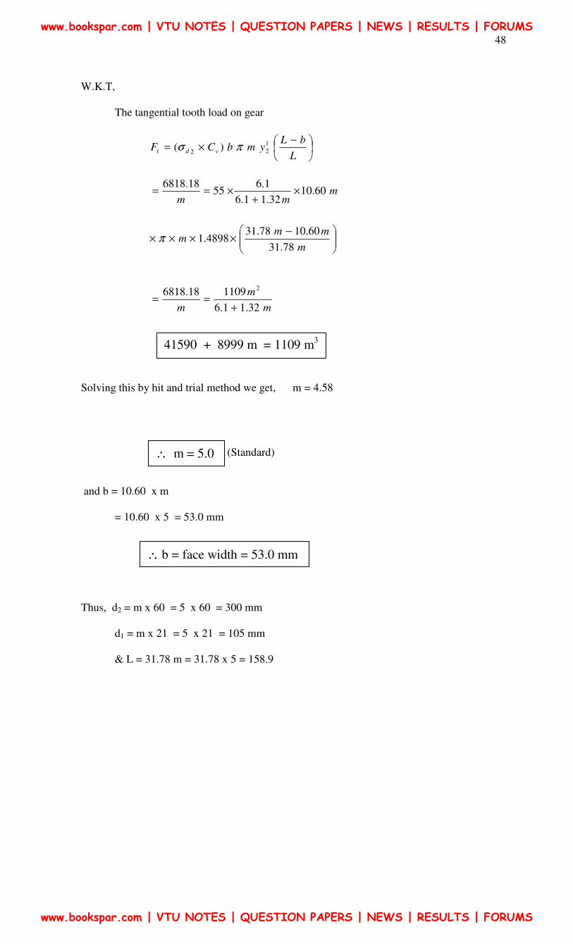
W.K.T,
The tangential tooth load on gear
−×=
L
bLymbCF vdt
1
22)( πσ
mmm
60.1032.11.6
1.655
18.6818×
+×==
−××××
m
mmm
78.31
60.1078.314898.1π
m
m
m 32.11.6
110918.68182
+==
Solving this by hit and trial method we get, m = 4.58
(Standard)
and b = 10.60 x m
= 10.60 x 5 = 53.0 mm
Thus, d2 = m x 60 = 5 x 60 = 300 mm
d1 = m x 21 = 5 x 21 = 105 mm
& L = 31.78 m = 31.78 x 5 = 158.9
41590 + 8999 m = 1109 m3
∴ m = 5.0
∴ b = face width = 53.0 mm
www.bookspar.com | VTU NOTES | QUESTION PAPERS | NEWS | RESULTS | FORUMS
www.bookspar.com | VTU NOTES | QUESTION PAPERS | NEWS | RESULTS | FORUMS
49
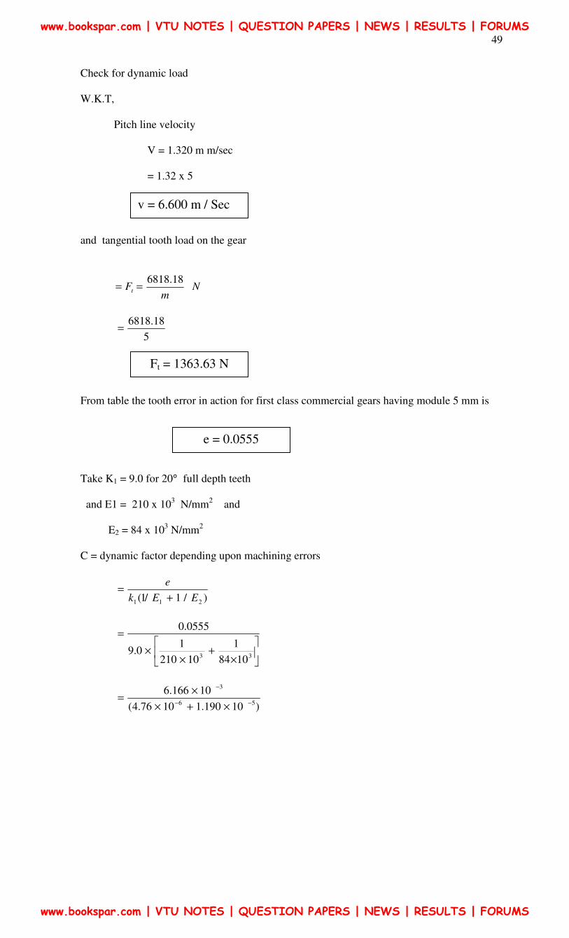
Check for dynamic load
W.K.T,
Pitch line velocity
V = 1.320 m m/sec
= 1.32 x 5
and tangential tooth load on the gear
Nm
Ft
18.6818==
5
18.6818=
From table the tooth error in action for first class commercial gears having module 5 mm is
Take K1 = 9.0 for 20° full depth teeth
and E1 = 210 x 103 N/mm
2 and
E2 = 84 x 103 N/mm
2
C = dynamic factor depending upon machining errors
)/1/1( 211 EEk
e
+=
×+
××
=
33 1084
1
10210
10.9
0555.0
)10190.11076.4(
10166.656
3
−−
−
×+×
×=
v = 6.600 m / Sec
Ft = 1363.63 N
e = 0.0555
www.bookspar.com | VTU NOTES | QUESTION PAPERS | NEWS | RESULTS | FORUMS
www.bookspar.com | VTU NOTES | QUESTION PAPERS | NEWS | RESULTS | FORUMS
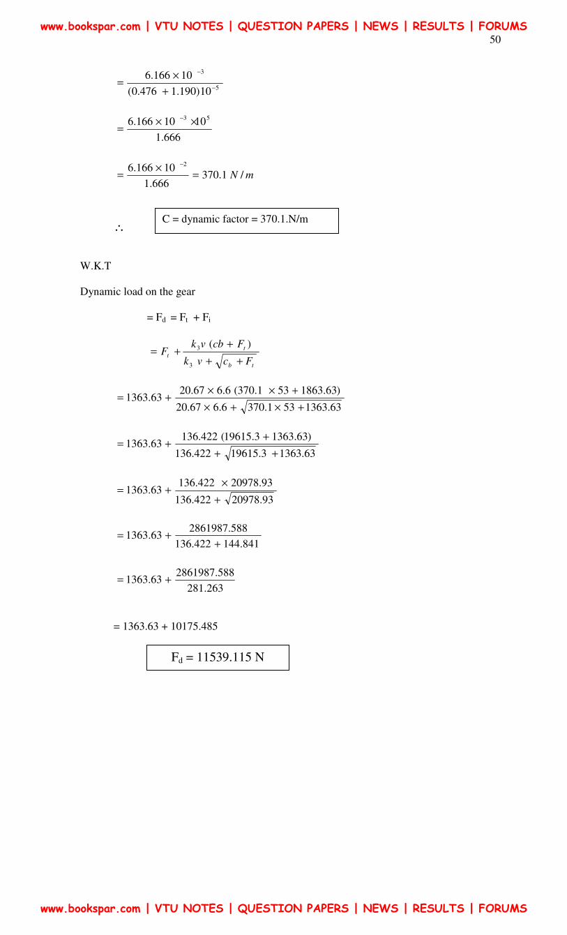
50
5
3
10)190.1476.0(
10166.6−
−
+
×=
666.1
1010166.6 53 ××=
−
mN /1.370666.1
10166.6 2
=×
=−
∴
W.K.T
Dynamic load on the gear
= Fd = Ft + Fi
tb
t
tFcvk
FcbvkF
++
++=
3
3 )(
63.1363531.3706.667.20
)63.1863531.370(6.667.2063.1363
+×+×
+××+=
63.13633.19615422.136
)63.13633.19615(422.13663.1363
++
++=
93.20978422.136
93.20978422.13663.1363
+
×+=
841.144422.136
588.286198763.1363
++=
263.281
588.286198763.1363 +=
= 1363.63 + 10175.485
Fd = 11539.115 N
C = dynamic factor = 370.1.N/m
www.bookspar.com | VTU NOTES | QUESTION PAPERS | NEWS | RESULTS | FORUMS
www.bookspar.com | VTU NOTES | QUESTION PAPERS | NEWS | RESULTS | FORUMS
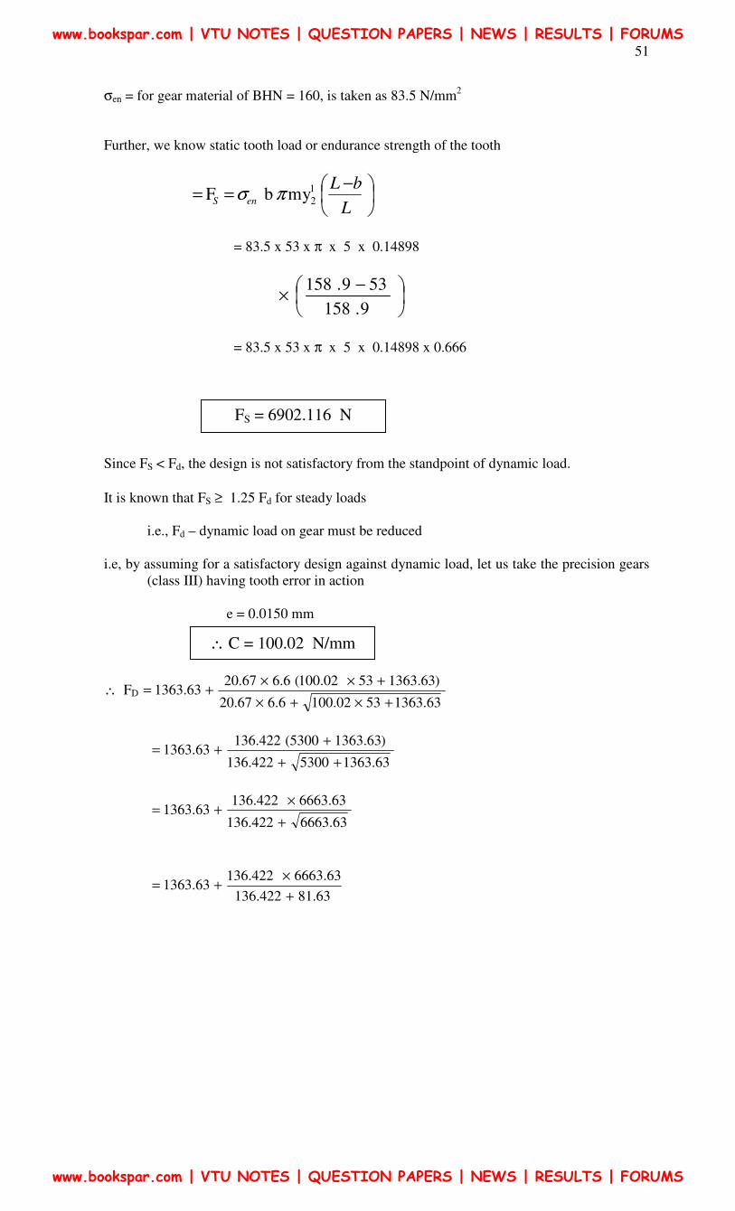
51
σen = for gear material of BHN = 160, is taken as 83.5 N/mm2
Further, we know static tooth load or endurance strength of the tooth
−==
L
bLenS
1
2ymbF πσ
= 83.5 x 53 x π x 5 x 0.14898
−×
9.158
539.158
= 83.5 x 53 x π x 5 x 0.14898 x 0.666
Since FS < Fd, the design is not satisfactory from the standpoint of dynamic load.
It is known that FS ≥ 1.25 Fd for steady loads
i.e., Fd – dynamic load on gear must be reduced
i.e, by assuming for a satisfactory design against dynamic load, let us take the precision gears
(class III) having tooth error in action
e = 0.0150 mm
∴ FD63.13635302.1006.667.20
)63.13635302.100(6.667.2063.1363
+×+×
+××+=
63.13635300422.136
)63.13635300(422.13663.1363
++
++=
63.6663422.136
63.6663422.13663.1363
+
×+=
63.81422.136
63.6663422.13663.1363
+
×+=
FS = 6902.116 N
∴ C = 100.02 N/mm
www.bookspar.com | VTU NOTES | QUESTION PAPERS | NEWS | RESULTS | FORUMS
www.bookspar.com | VTU NOTES | QUESTION PAPERS | NEWS | RESULTS | FORUMS
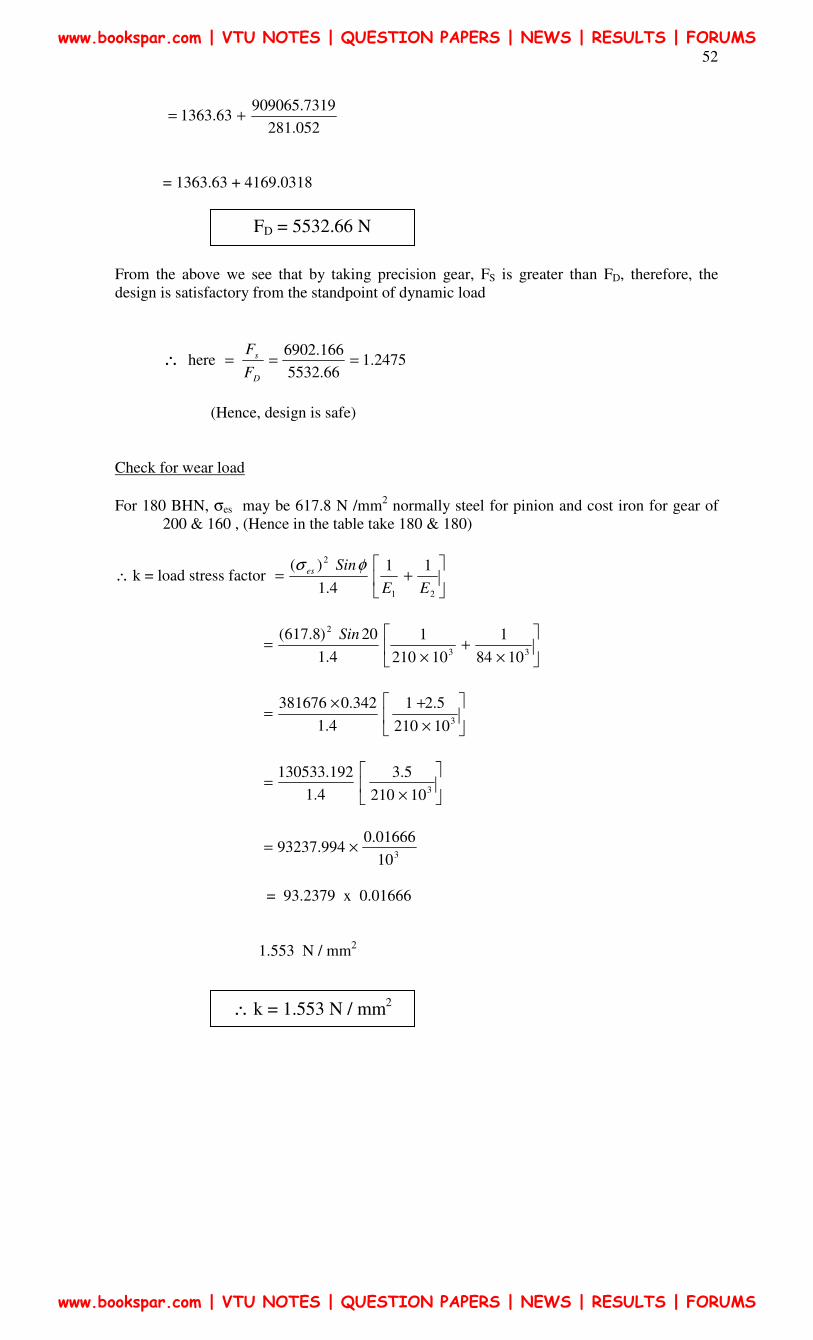
52
052.281
7319.90906563.1363 +=
= 1363.63 + 4169.0318
From the above we see that by taking precision gear, FS is greater than FD, therefore, the
design is satisfactory from the standpoint of dynamic load
∴ here 2475.166.5532
166.6902===
D
s
F
F
(Hence, design is safe)
Check for wear load
For 180 BHN, σes may be 617.8 N /mm2 normally steel for pinion and cost iron for gear of
200 & 160 , (Hence in the table take 180 & 180)
∴ k = load stress factor
+=
21
211
4.1
)(
EE
Sines φσ
×+
×=
33
2
1084
1
10210
1
4.1
20)8.617( Sin
×
+×=
310210
5.21
4.1
342.0381676
×=
310210
5.3
4.1
192.130533
310
01666.0994.93237 ×=
= 93.2379 x 0.01666
1.553 N / mm2
FD = 5532.66 N
∴ k = 1.553 N / mm2
www.bookspar.com | VTU NOTES | QUESTION PAPERS | NEWS | RESULTS | FORUMS
www.bookspar.com | VTU NOTES | QUESTION PAPERS | NEWS | RESULTS | FORUMS
53
and
Qe = ratio factor
54.18125.22
54.18122
2
2
+
×=
+=
ZeZe
Ze
78.179.203
08.363==
W.K.T
Maximum or limiting load for wear
= FW = d1* b Qe K (*? For pinion, please explain)
= 105 x 53 x 1.78 x 1.553
Since, Fw is greater than FD the design is satisfactory from the standpoint of wear also
Fw = 15397.70 N
www.bookspar.com | VTU NOTES | QUESTION PAPERS | NEWS | RESULTS | FORUMS
www.bookspar.com | VTU NOTES | QUESTION PAPERS | NEWS | RESULTS | FORUMS