Embed Size (px)
Citation preview
www.torex.co.jp/english
Spring/Summer 2014
Power Management Solutions
1.5A, 5.5VCONSTANT ON TIME
ONLY 2.5 x 3.2 x 1.0mm
IN THIS ISSUEXCL213/14 1.5A, Hi-SAT-COT Step-Down Micro DC/DC Converter with Integrated Coil
XC8107/08/09 85m� High Function Power Switch
XCL211/12 2A Step-Down Micro DC/DC Converter with Integrated Coil
XC9270/71 30V, 2A Step-Down DC/DC Converter
XCL101 Ultra Low Power, Step-Up, Micro DC/DC with Integrated Coil
XC9252 30V, Low Power Step-Down DC/DC Controller
XC9306 Synchronous Buck-Boost DC/DC Converter
XC9248 2A, 18V Synchronous Step-Down DC/DC Converter
XC9131/35/36 Synchronous Step-Up DC/DC Converter
XC9260/61 1.5A Hi-SAT-COT Synchronous Step-Down DC/DC Converter
INCLUDES 6 PAGE SELECTION GUIDE
MICRO DC/DC WITH INTEGRATED COIL
2
POWER SWITCH
XC8107/08/09 85m� High Function Power Switch
ON Resistance 85m� (typ)
Maximum Output Current See Table Below
Output Current Limit See Table Below
Input Voltage 2.5V ~ 5.5V
Current Limit Response Time 2μs (typ)
Current Limit Accuracy ±10%
Turn-On Time 0.6ms (typ)
Supply Current 40μA
Standby Supply Current 0.1μA (max)
Protection Circuits
Current Limit
Short Circuit Protection
Thermal Shutdown
Under Voltage Lockout(UVLO)
Soft-start
Op. Ambient Temperature -40˚C ~ +105˚C
Additional Features: Flag Output & High speed CL discharge
Packages: USP-6C, SOT-25 (XC8107 only)
AUTO RECOVERY TYPE
CURRENT LIMIT CIRCUIT TYPES
SELECTION GUIDE
LATCH TYPE
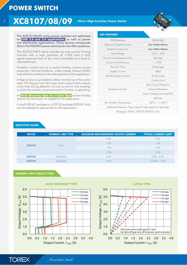
DEVICE CURRENT LIMIT TYPE MAXIMUM RECOMMENDED OUTPUT CURRENT TYPICAL CURRENT LIMIT
XC8107 Fixed
0.5A 0.9A
1.0A 1.4A
1.5A 1.9A
2.0A 2.4A
XC8108 Adjustable 2.0A 0.9A – 2.4A
XC8109 Adjustable 0.9A 0.075A – 1.3A
The XC8107/08/09 series power switches are optimised for USB 2.0 and 3.0 applications, as well as power line distribution applications. These devices incorporate 85m� Pch MOSFET power switches for low ON resistance.
The XC8107/08/9 series includes an over-current limiting function with a high precision of ±10% and a high speed response time of 2μs and is available as a fixed or adjustable type.
Protection circuits such as a current limiting, reverse current prevention, thermal shutdown, under-voltage lockout (UVLO) and soft start contribute to the safe operation of the application.
A flag function is provided to allow monitoring of the switch state. The flag pin is an Nch open drain output which outputs a low level during detection of over-current or over-heating, or while the reverse current prevention function is operating.
An Auto Recovery Type or a Latch Type current limiting feature can be chosen as needed for the application.
A small USP-6C package or a SOT-25 package (XC8107 only) can be selected as appropriate for the application.
KEY FEATURES
3
www.torex.co.jp/english
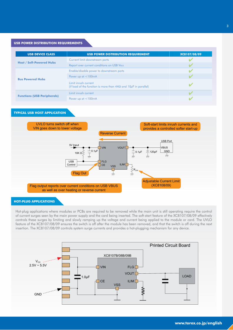
Hot-plug applications where modules or PCBs are required to be removed while the main unit is still operating require the control of current surges seen by the main power supply and the card being inserted. The soft-start feature of the XC8107/08/09 effectively controls these surges by limiting and slowly ramping up the voltage and current being applied to the module or card. The UVLO feature of the XC8107/08/09 ensures the switch is off after the module has been removed, and that the switch is off during the next insertion. The XC8107/08/09 controls system surge currents and provides a hot-plugging mechanism for any device.
HOT-PLUG APPLICATIONS
TYPICAL USB HOST APPLICATION
USB POWER DISTRIBUTION REQUIREMENTS
USB DEVICE CLASS USB POWER DISTRIBUTION REQUIREMENT XC8107/08/09
Host / Self-Powered HubsCurrent limit downstream ports �Report over current conditions on USB VBUS �
Bus Powered Hubs
Enable/disable power to downstream ports �Power up at <100mA �
Limit inrush current(if load of the function is more than 44� and 10μF in parallel) �
Functions (USB Peripherals)Limit inrush current �Power up at <100mA �
4
STEP-DOWN DC/DC
XC9270/71 30V, 2A Step-Down DC/DC Converter
KEY FEATURES
TYPICAL APPLICATION CIRCUIT
EFFICIENCY VS. OUTPUT CURRENT
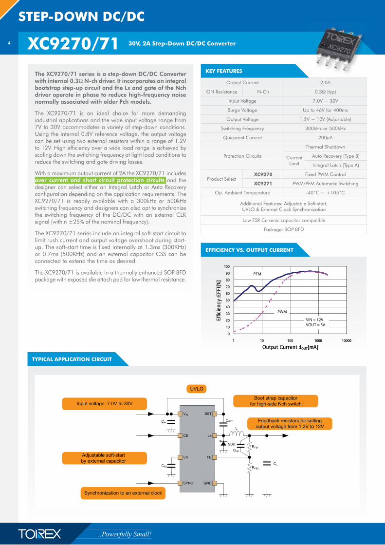
Output Current 2.0A
ON Resistance N-Ch 0.3� (typ)
Input Voltage 7.0V ~ 30V
Surge Voltage Up to 46V for 400ms
Output Voltage 1.2V ~ 12V (Adjustable)
Switching Frequency 300kHz or 500kHz
Quiescent Current 200μA
Protection Circuits
Thermal Shutdown
Current Limit
Auto Recovery (Type B)
Integral Latch (Type A)
Product SelectXC9270 Fixed PWM Control
XC9271 PWM/PFM Automatic Switching
Op. Ambient Temperature -40˚C ~ +105˚C
Additional Features: Adjustable Soft-start, UVLO & External Clock Synchronization
Low ESR Ceramic capacitor compatible
Package: SOP-8FD
The XC9270/71 series is a step-down DC/DC Converter with internal 0.3� N-ch driver. It incorporates an integral bootstrap step-up circuit and the Lx and gate of the Nch driver operate in phase to reduce high-frequency noise normally associated with older Pch models.
The XC9270/71 is an ideal choice for more demanding industrial applications and the wide input voltage range from 7V to 30V accommodates a variety of step-down conditions. Using the internal 0.8V reference voltage, the output voltage can be set using two external resistors within a range of 1.2V to 12V. High efficiency over a wide load range is achieved by scaling down the switching frequency at light load conditions to reduce the switching and gate driving losses.
With a maximum output current of 2A the XC9270/71 includes over current and short circuit protection circuits and the designer can select either an Integral Latch or Auto Recovery configuration depending on the application requirements. The XC9270/71 is readily available with a 300kHz or 500kHz switching frequency and designers can also opt to synchronize the switching frequency of the DC/DC with an external CLK signal (within ±25% of the nominal frequency).
The XC9270/71 series include an integral soft-start circuit to limit rush current and output voltage overshoot during start-up. The soft-start time is fixed internally at 1.3ms (300KHz) or 0.7ms (500KHz) and an external capacitor CSS can be connected to extend the time as desired.
The XC9270/71 is available in a thermally enhanced SOP-8FD package with exposed die attach pad for low thermal resistance.
KEY FEATURES
5
www.torex.co.jp/english
Integral latch method
When the current limiting state continues for a certain time, the limiting circuit of type A latches and turns off the Nch driver transistor. In order to restart operation by soft start once in the latched state.
VIN voltage must be briefly lowered below the UVLO detection voltage
AUTOMOTIVE LOAD DUMP PROTECTION
OVER CURRENT AND SHORT CIRCUIT PROTECTION
Auto Recovery Method
The current limiting circuits of type B combine both current limiting and short-circuit protection.
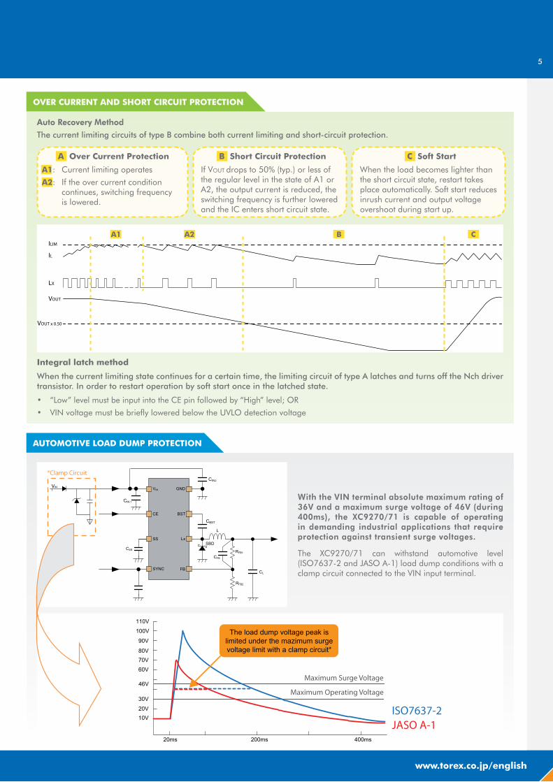
With the VIN terminal absolute maximum rating of 36V and a maximum surge voltage of 46V (during 400ms), the XC9270/71 is capable of operating in demanding industrial applications that require protection against transient surge voltages.
The XC9270/71 can withstand automotive level (ISO7637-2 and JASO A-1) load dump conditions with a clamp circuit connected to the VIN input terminal.
A Over Current Protection
A1: Current limiting operates
A2: If the over current condition continues, switching frequency is lowered.
B Short Circuit Protection
If VOUT drops to 50% (typ.) or less of the regular level in the state of A1 or A2, the output current is reduced, the switching frequency is further lowered and the IC enters short circuit state.
C Soft Start
When the load becomes lighter than the short circuit state, restart takes place automatically. Soft start reduces inrush current and output voltage overshoot during start up.
6
STEP-DOWN DC/DC
XC9252 30V, Low Power Step-Down DC/DC Controller
TYPICAL APPLICATION CIRCUIT
EFFICIENCY VS. OUTPUT CURRENT
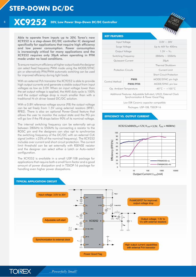
Able to operate from inputs up to 30V, Torex’s new XC9252 is a step-down DC/DC controller IC designed specifically for applications that require high efficiency and low power consumption. Power consumption is increasingly critical for many applications and the XC9252 requires only 30μA when operating in PFM mode under no load conditions.
To ensure maximum efficiency at higher output loads the designer can select fixed frequency PWM mode using the MODE/SYNC pin or alternatively PFM/PWM automatic switching can be used for improved efficiency during light loads.
With an external Pch transistor the XC9252 is able to provide high output currents and generate a stable output from input voltages as low as 3.0V. When an input voltage lower than the set output voltage is applied, the MAX duty cycle is 100% and the output voltage drop is much smaller than with a traditional N-ch driver based DC/DC solution.
With a 0.8V reference voltage source (FB) the output voltage can be set freely from 1.5V using external resistors (RFB1, RFB2). There is also an optional Power-Good feature that allows the user to monitor the output state and the PG pin will go low if the FB drops below 90% of its nominal voltage.
The internal switching frequency can be externally set-up between 280kHz to 550kHz by connecting a resistor to the ROSC pin and the designers can also opt to synchronize the switching frequency of the DC/DC with an external CLK signal (within ±25% of the nominal frequency). The XC9252 includes over current and short circuit protection. The current limit threshold can be set externally with RSENSE resistor and the designer can select either a Latch or Auto-restart configuration.
The XC9252 is available in a small USP-10B package for applications that require both a small form factor and a good amount of power dissipation and in TSSOP-16 package for handling even higher power dissipations.
Input Voltage 3.0V ~ 30V
Surge Voltage Up to 46V for 400ms
Output Voltage 1.5V ~ VIN
Switching Frequency 280kHz ~ 550kHz
Quiescent Current 30μA
Protection Circuits
Thermal Shutdown
Current Limit
Short Circuit Protection
Control MethodPWM MODE/SYNC pin high
PWM/PFM MODE/SYNC pin low
Op. Ambient Temperature -40˚C ~ +105˚C
Additional Features: Adjustable Soft-start, UVLO, External Clock Synchronization & Power Good Flag
Low ESR Ceramic capacitor compatible
Packages: USP-10B, TSSOP-16
KEY FEATURES
7
www.torex.co.jp/english
XC9248 2.2A, 18V Synchronous Step-Down DC/DC Converter
TYPICAL APPLICATION CIRCUIT
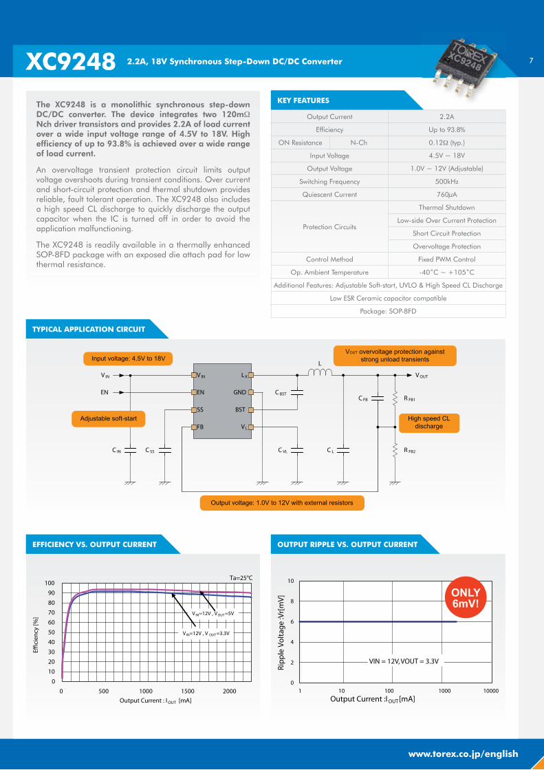
Output Current 2.2A
Efficiency Up to 93.8%
ON Resistance N-Ch 0.12� (typ.)
Input Voltage 4.5V ~ 18V
Output Voltage 1.0V ~ 12V (Adjustable)
Switching Frequency 500kHz
Quiescent Current 760μA
Protection Circuits
Thermal Shutdown
Low-side Over Current Protection
Short Circuit Protection
Overvoltage Protection
Control Method Fixed PWM Control
Op. Ambient Temperature -40˚C ~ +105˚C
Additional Features: Adjustable Soft-start, UVLO & High Speed CL Discharge
Low ESR Ceramic capacitor compatible
Package: SOP-8FD
The XC9248 is a monolithic synchronous step-down DC/DC converter. The device integrates two 120m� Nch driver transistors and provides 2.2A of load current over a wide input voltage range of 4.5V to 18V. High efficiency of up to 93.8% is achieved over a wide range of load current.
An overvoltage transient protection circuit limits output voltage overshoots during transient conditions. Over current and short-circuit protection and thermal shutdown provides reliable, fault tolerant operation. The XC9248 also includes a high speed CL discharge to quickly discharge the output capacitor when the IC is turned off in order to avoid the application malfunctioning.
The XC9248 is readily available in a thermally enhanced SOP-8FD package with an exposed die attach pad for low thermal resistance.
EFFICIENCY VS. OUTPUT CURRENT OUTPUT RIPPLE VS. OUTPUT CURRENT
KEY FEATURES
8
STEP-DOWN DC/DC
XC9260/61 1.5A, HiSAT-COT Synchronous Step-Down DC/DC Converter
KEY FEATURES
TYPICAL APPLICATION CIRCUIT
EFFICIENCY VS. OUTPUT CURRENT OUTPUT RIPPLE VS. OUTPUT CURRENT
OSCILLATION FREQUENCY VS. OUTPUT CURRENT
KEY FEATURES
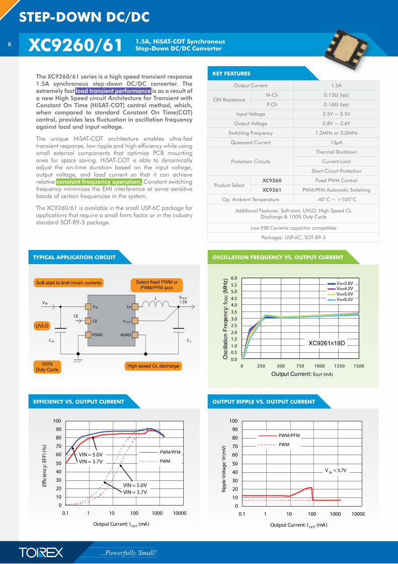
Output Current 1.5A
ON ResistanceN-Ch 0.13� (typ)
P-Ch 0.16� (typ)
Input Voltage 2.5V ~ 5.5V
Output Voltage 0.8V ~ 3.6V
Switching Frequency 1.2MHz or 3.0MHz
Quiescent Current 15μA
Protection Circuits
Thermal Shutdown
Current Limit
Short Circuit Protection
Product SelectXC9260 Fixed PWM Control
XC9261 PWM/PFM Automatic Switching
Op. Ambient Temperature -40˚C ~ +105˚C
Additional Features: Soft-start, UVLO, High Speed CL Discharge & 100% Duty Cycle
Low ESR Ceramic capacitor compatible
Packages: USP-6C, SOT-89-5
The XC9260/61 series is a high speed transient response 1.5A synchronous step-down DC/DC converter. The extremely fast load transient performance is as a result of a new High Speed circuit Architecture for Transient with Constant On Time (HiSAT-COT) control method, which, when compared to standard Constant On Time(COT) control, provides less fluctuation in oscillation frequency against load and input voltage.
The unique HiSAT-COT architecture enables ultra-fast transient response, low ripple and high efficiency while using small external components that optimise PCB mounting area for space saving. HiSAT-COT is able to dynamically adjust the on-time duration based on the input voltage, output voltage, and load current so that it can achieve relative constant frequency operation. Constant switching frequency minimizes the EMI interference at some sensitive bands of certain frequencies in the system.
The XC9260/61 is available in the small USP-6C package for applications that require a small form factor or in the industry standard SOT-89-5 package.
9
www.torex.co.jp/english
LOAD TRANSIENT RESPONSE
SPECIFICATION / SERIESUNDER DEVELOPMENT
XC9257/58UNDER DEVELOPMENT
XC9259 XC9260/61UNDER DEVELOPMENT
XC9262
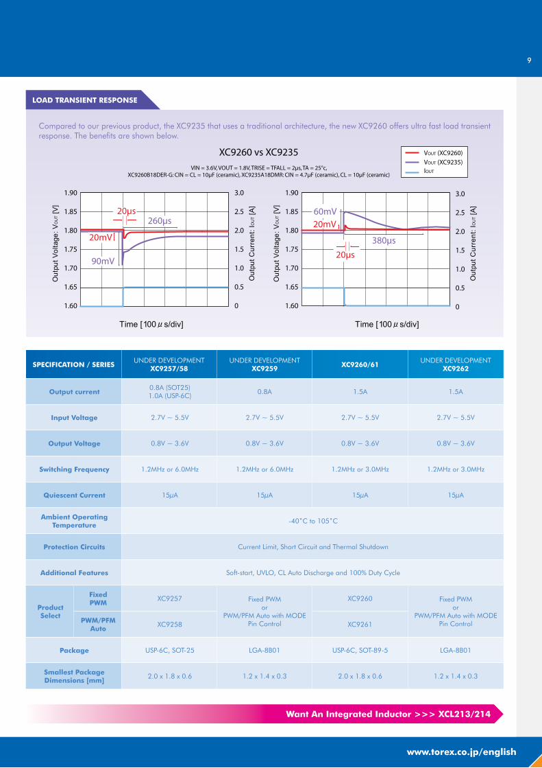
Output current0.8A (SOT25)1.0A (USP-6C)
0.8A 1.5A 1.5A
Input Voltage 2.7V ~ 5.5V 2.7V ~ 5.5V 2.7V ~ 5.5V 2.7V ~ 5.5V
Output Voltage 0.8V ~ 3.6V 0.8V ~ 3.6V 0.8V ~ 3.6V 0.8V ~ 3.6V
Switching Frequency 1.2MHz or 6.0MHz 1.2MHz or 6.0MHz 1.2MHz or 3.0MHz 1.2MHz or 3.0MHz
Quiescent Current 15μA 15μA 15μA 15μA
Ambient Operating Temperature
-40˚C to 105˚C
Protection Circuits Current Limit, Short Circuit and Thermal Shutdown
Additional Features Soft-start, UVLO, CL Auto Discharge and 100% Duty Cycle
Product Select
Fixed PWM
XC9257 Fixed PWMor
PWM/PFM Auto with MODE Pin Control
XC9260 Fixed PWMor
PWM/PFM Auto with MODE Pin ControlPWM/PFM
AutoXC9258 XC9261
Package USP-6C, SOT-25 LGA-8B01 USP-6C, SOT-89-5 LGA-8B01
Smallest Package Dimensions [mm]
2.0 x 1.8 x 0.6 1.2 x 1.4 x 0.3 2.0 x 1.8 x 0.6 1.2 x 1.4 x 0.3
Compared to our previous product, the XC9235 that uses a traditional architecture, the new XC9260 offers ultra fast load transient response. The benefits are shown below.
Want An Integrated Inductor >>> XCL213/214
10
MICRO DC/DC
XCL213/14 1.5A, HiSAT-COT Step-Down Micro DC/DC Converter with Integrated Coil
XCL211/12 2A Step-Down Micro DC/DC Converter with Integrated Coil
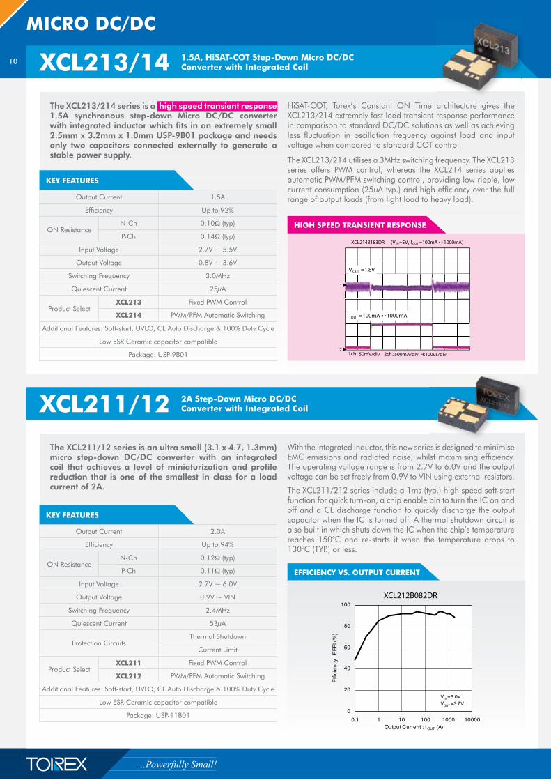
HIGH SPEED TRANSIENT RESPONSE
KEY FEATURES
Output Current 1.5A
Efficiency Up to 92%
ON ResistanceN-Ch 0.10� (typ)
P-Ch 0.14� (typ)
Input Voltage 2.7V ~ 5.5V
Output Voltage 0.8V ~ 3.6V
Switching Frequency 3.0MHz
Quiescent Current 25μA
Product SelectXCL213 Fixed PWM Control
XCL214 PWM/PFM Automatic Switching
Additional Features: Soft-start, UVLO, CL Auto Discharge & 100% Duty Cycle
Low ESR Ceramic capacitor compatible
Package: USP-9B01
The XCL211/12 series is an ultra small (3.1 x 4.7, 1.3mm) micro step-down DC/DC converter with an integrated coil that achieves a level of miniaturization and profile reduction that is one of the smallest in class for a load current of 2A.
With the integrated Inductor, this new series is designed to minimise EMC emissions and radiated noise, whilst maximising efficiency. The operating voltage range is from 2.7V to 6.0V and the output voltage can be set freely from 0.9V to VIN using external resistors.
The XCL211/212 series include a 1ms (typ.) high speed soft-start function for quick turn-on, a chip enable pin to turn the IC on and off and a CL discharge function to quickly discharge the output capacitor when the IC is turned off. A thermal shutdown circuit is also built in which shuts down the IC when the chip’s temperature reaches 150°C and re-starts it when the temperature drops to 130°C (TYP.) or less.
KEY FEATURES
Output Current 2.0A
Efficiency Up to 94%
ON ResistanceN-Ch 0.12� (typ)
P-Ch 0.11� (typ)
Input Voltage 2.7V ~ 6.0V
Output Voltage 0.9V ~ VIN
Switching Frequency 2.4MHz
Quiescent Current 53μA
Protection CircuitsThermal Shutdown
Current Limit
Product SelectXCL211 Fixed PWM Control
XCL212 PWM/PFM Automatic Switching
Additional Features: Soft-start, UVLO, CL Auto Discharge & 100% Duty Cycle
Low ESR Ceramic capacitor compatible
Package: USP-11B01
EFFICIENCY VS. OUTPUT CURRENT
es is designed to minimise i i i ffi i
The XCL213/214 series is a high speed transient response 1.5A synchronous step-down Micro DC/DC converter with integrated inductor which fits in an extremely small 2.5mm x 3.2mm x 1.0mm USP-9B01 package and needs only two capacitors connected externally to generate a stable power supply.
HiSAT-COT, Torex’s Constant ON Time architecture gives the XCL213/214 extremely fast load transient response performance in comparison to standard DC/DC solutions as well as achieving less fluctuation in oscillation frequency against load and input voltage when compared to standard COT control.
The XCL213/214 utilises a 3MHz switching frequency. The XCL213 series offers PWM control, whereas the XCL214 series applies automatic PWM/PFM switching control, providing low ripple, low current consumption (25uA typ.) and high efficiency over the full range of output loads (from light load to heavy load).
11
www.torex.co.jp/english
XCL101 Ultra Low Power, Step-Up, Micro DC/DC Converter with Integrated Coil
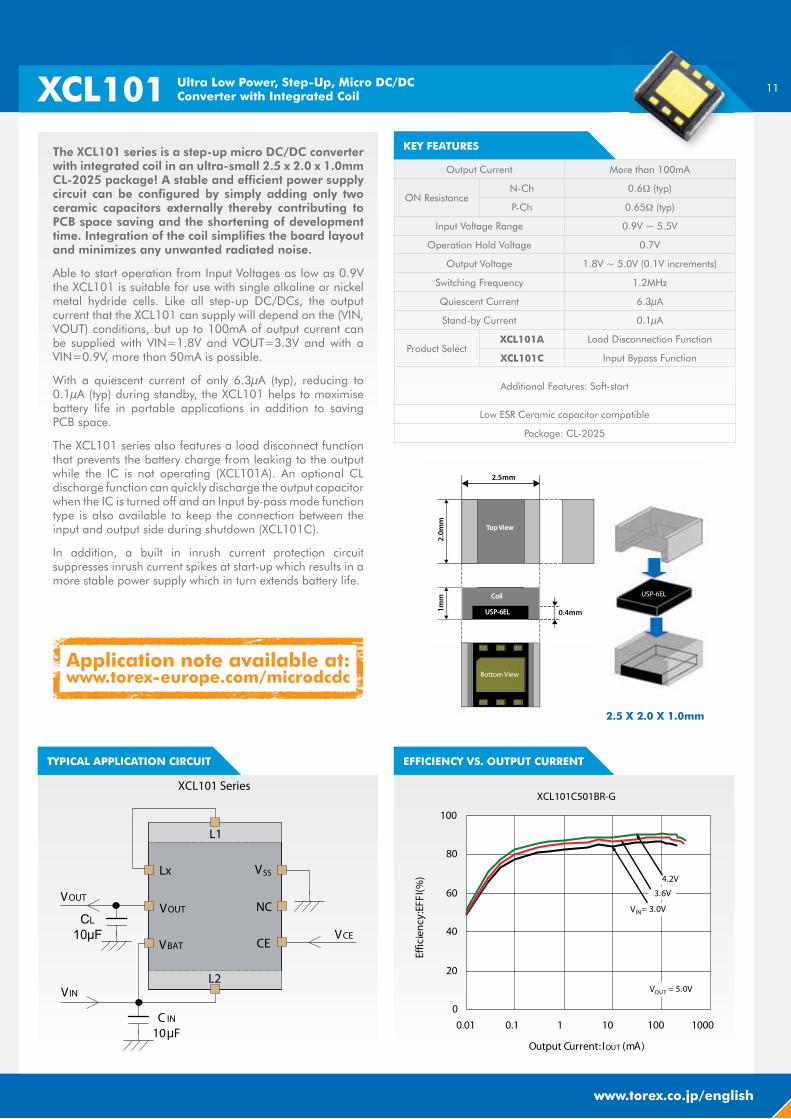
KEY FEATURESThe XCL101 series is a step-up micro DC/DC converter with integrated coil in an ultra-small 2.5 x 2.0 x 1.0mm CL-2025 package! A stable and efficient power supply circuit can be configured by simply adding only two ceramic capacitors externally thereby contributing to PCB space saving and the shortening of development time. Integration of the coil simplifies the board layout and minimizes any unwanted radiated noise.
Able to start operation from Input Voltages as low as 0.9V the XCL101 is suitable for use with single alkaline or nickel metal hydride cells. Like all step-up DC/DCs, the output current that the XCL101 can supply will depend on the (VIN, VOUT) conditions, but up to 100mA of output current can be supplied with VIN=1.8V and VOUT=3.3V and with a VIN=0.9V, more than 50mA is possible.
With a quiescent current of only 6.3μA (typ), reducing to 0.1μA (typ) during standby, the XCL101 helps to maximise battery life in portable applications in addition to saving PCB space.
The XCL101 series also features a load disconnect function that prevents the battery charge from leaking to the output while the IC is not operating (XCL101A). An optional CL discharge function can quickly discharge the output capacitor when the IC is turned off and an Input by-pass mode function type is also available to keep the connection between the input and output side during shutdown (XCL101C).
In addition, a built in inrush current protection circuit suppresses inrush current spikes at start-up which results in a more stable power supply which in turn extends battery life.
EFFICIENCY VS. OUTPUT CURRENTTYPICAL APPLICATION CIRCUIT
Output Current More than 100mA
ON ResistanceN-Ch 0.6� (typ)
P-Ch 0.65� (typ)
Input Voltage Range 0.9V ~ 5.5V
Operation Hold Voltage 0.7V
Output Voltage 1.8V ~ 5.0V (0.1V increments)
Switching Frequency 1.2MHz
Quiescent Current 6.3μA
Stand-by Current 0.1μA
Product SelectXCL101A Load Disconnection Function
XCL101C Input Bypass Function
Additional Features: Soft-start
Low ESR Ceramic capacitor compatible
Package: CL-2025
2.5 X 2.0 X 1.0mm
Application note available at:www.torex-europe.com/microdcdc
12
BUCK-BOOST DC/DC
XC9306 Synchronous Buck-Boost DC/DC Converter
KEY FEATURES
TYPICAL APPLICATION CIRCUIT
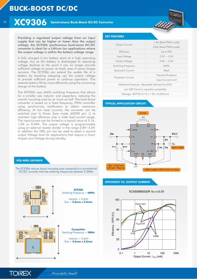
Providing a regulated output voltage from an input supply that can be higher or lower than the output voltage, the XC9306 synchronous buck-boost DC/DC converter is ideal for a Lithium Ion applications where the output voltage is within the battery voltage range.
A fully charged Li-ion battery starts at a high operating voltage, but as the battery is discharged its operating voltage declines to the point it can no longer provide sufficient voltage to power its load, even if some charge remains. The XC9306 can extend the usable life of a battery by boosting (stepping up) the output voltage to provide sufficient power to continue operation. This extends battery life by more efficiently using the remaining charge of the battery.
The XC9306 uses 6MHz switching frequency that allows for a smaller size inductor and capacitors, reducing the overall mounting area by as much as half. The buck-boost converter is based on a fixed frequency, PWM controller using synchronous rectification to obtain maximum efficiency. At low load currents, the converter can be switched over to Power Save mode (MODE pin: L) to maintain high efficiency over a wide load current range. The input current can be limited to a typical value of 3.1A, 1.3A or 0.49A. The output voltage is programmable using an external resistor divider in the range 0.8V~5.0V. In addition the VSEL pin can be used to select a second output Voltage level for applications that require a lower chipset core Voltage during standby.
PCB AREA SAVINGS
EFFICIENCY VS. OUTPUT CURRENT
Output Current1.2A (Buck PWM-mode)
0.8A (Boost PWM-mode)
Efficiency Up to 92%
Input Voltage 2.5V ~ 5.5V
Output Voltage 0.8V ~ 5.0V
Switching Frequency 6MHz
Quiescent Current 50μA
Protection CircuitsThermal Shutdown
Input Current Limit
Additional Features: Adjustable Soft-start & UVLO
Low ESR Ceramic capacitor compatible
Package: WLP-20 (2.15 x 1.94 x 0.625mm)
The XC9306 reduces board mounting area compared to a conventional DC/DC converter that has switching frequencies between 2-3MHz.
XC9306 Switching Frequency = 6MHz
Inductor = 0.5μHSize = 2.0mm x 2.0mm
Competitor Switching Frequency = 2MHz
Inductor = 2.2μHSize = 4.0mm x 4.0mm
13
www.torex.co.jp/english
STEP-UP DC/DC
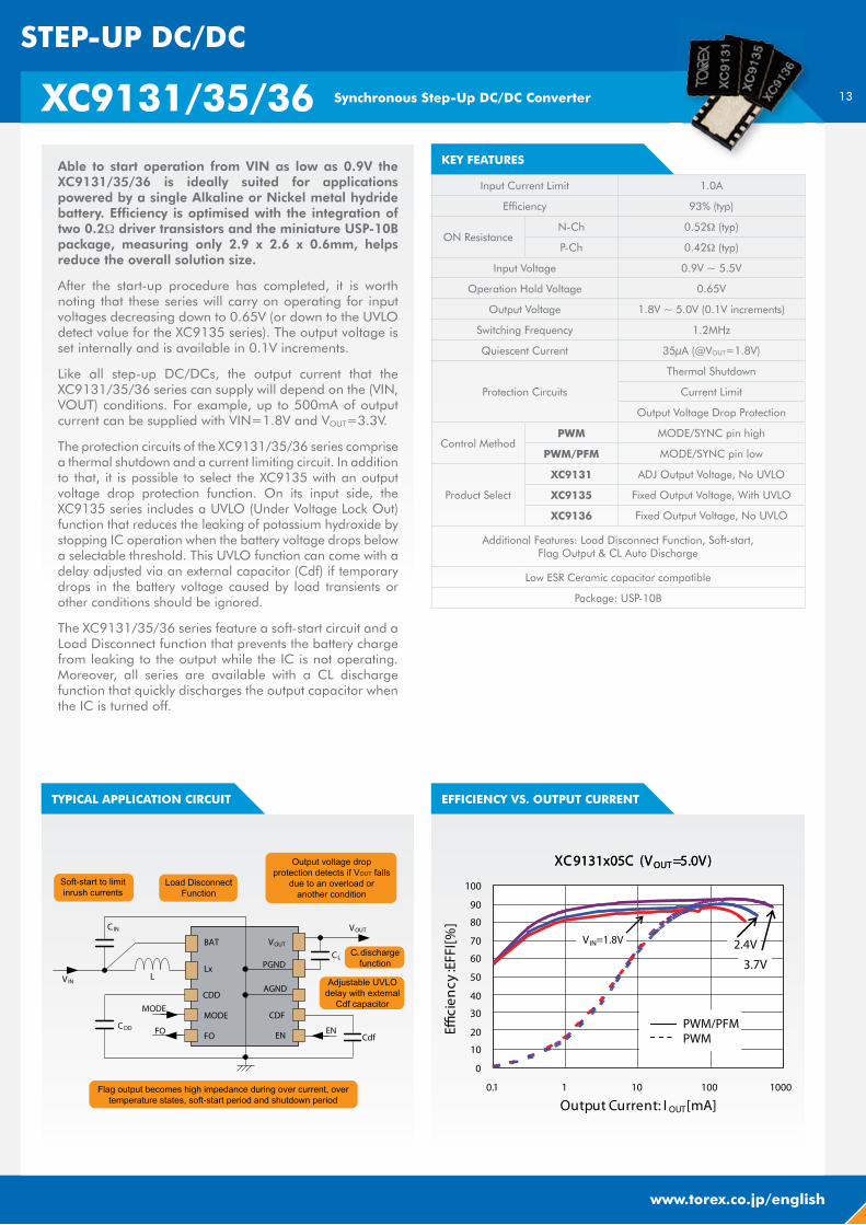
KEY FEATURESAble to start operation from VIN as low as 0.9V the XC9131/35/36 is ideally suited for applications powered by a single Alkaline or Nickel metal hydride battery. Efficiency is optimised with the integration of two 0.2� driver transistors and the miniature USP-10B package, measuring only 2.9 x 2.6 x 0.6mm, helps reduce the overall solution size.
After the start-up procedure has completed, it is worth noting that these series will carry on operating for input voltages decreasing down to 0.65V (or down to the UVLO detect value for the XC9135 series). The output voltage is set internally and is available in 0.1V increments.
Like all step-up DC/DCs, the output current that the XC9131/35/36 series can supply will depend on the (VIN, VOUT) conditions. For example, up to 500mA of output current can be supplied with VIN=1.8V and VOUT=3.3V.
The protection circuits of the XC9131/35/36 series comprise a thermal shutdown and a current limiting circuit. In addition to that, it is possible to select the XC9135 with an output voltage drop protection function. On its input side, the XC9135 series includes a UVLO (Under Voltage Lock Out) function that reduces the leaking of potassium hydroxide by stopping IC operation when the battery voltage drops below a selectable threshold. This UVLO function can come with a delay adjusted via an external capacitor (Cdf) if temporary drops in the battery voltage caused by load transients or other conditions should be ignored.
The XC9131/35/36 series feature a soft-start circuit and a Load Disconnect function that prevents the battery charge from leaking to the output while the IC is not operating. Moreover, all series are available with a CL discharge function that quickly discharges the output capacitor when the IC is turned off.
TYPICAL APPLICATION CIRCUIT EFFICIENCY VS. OUTPUT CURRENT
XC9131/35/36 Synchronous Step-Up DC/DC Converter
Input Current Limit 1.0A
Efficiency 93% (typ)
ON ResistanceN-Ch 0.52� (typ)
P-Ch 0.42� (typ)
Input Voltage 0.9V ~ 5.5V
Operation Hold Voltage 0.65V
Output Voltage 1.8V ~ 5.0V (0.1V increments)
Switching Frequency 1.2MHz
Quiescent Current 35μA (@VOUT=1.8V)
Protection Circuits
Thermal Shutdown
Current Limit
Output Voltage Drop Protection
Control MethodPWM MODE/SYNC pin high
PWM/PFM MODE/SYNC pin low
Product Select
XC9131 ADJ Output Voltage, No UVLO
XC9135 Fixed Output Voltage, With UVLO
XC9136 Fixed Output Voltage, No UVLO
Additional Features: Load Disconnect Function, Soft-start, Flag Output & CL Auto Discharge
Low ESR Ceramic capacitor compatible
Package: USP-10B
14
SELECTION GUIDE
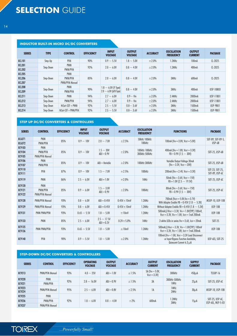
INDUCTOR BUILT-IN MICRO DC/DC CONVERTERS
SERIES TYPE CONTROL EFFICIENCY INPUT VOLTAGE
OUTPUT VOLTAGE ACCURACY OSCILLATION
FREQUENCYOUTPUT CURRENT PACKAGE
XCL101 Step-Up PFM 90% 0.9 ~ 5.5V 1.8 ~ 5.0V ±2.0% 1.2MHz 100mA CL-2025XCL201
Step-DownPWM
92% 2.0 ~ 6.0V 0.8 ~ 4.0V ±2.0% 1.2MHz 400mA CL-2025XCL202 PWM/PFMXCL205
Step-DownPWM
85% 2.0 ~ 6.0V 0.8 ~ 4.0V ±2.0% 3MHz 600mA CL-2025XCL206 PWM/PFMXCL207 PWM/PFM ManualXCL208
Step-DownPWM
90% 1.8 ~ 6.0V (F Type) 2.0 ~ 6.0V (A/B Type) 0.8 ~ 4.0V ±2.0% 3MHz 400mA USP-10B03
XCL209 PWM/PFMXCL211 Step-Down PWM 94% 2.7 ~ 6.0V 0.9~ Vin ±2.0% 2.4MHz 2000mA USP-11B01XCL212 Step-Down PWM/PFM 94% 2.7 ~ 6.0V 0.9~ Vin ±2.0% 2.4MHz 2000mA USP-11B01XCL213 Step-Down HiSat-COT+PWM 92% 2.5 ~ 5.5V 0.8~ 3.6V ±2.0% 3MHz 1500mA USP-9B01XCL214 Step-Down HiSat-COT+PWM/PFM 92% 2.5 ~ 5.5V 0.8~ 3.6V ±2.0% 3MHz 1500mA USP-9B01
STEP UP DC/DC CONVERTERS & CONTROLLERS
SERIES CONTROL EFFICIENCY INPUTVOLTAGE
OUTPUTVOLTAGE ACCURACY OSCILLATION
FREQUENCY FUNCTIONS PACKAGE
XC6371 PWM85% 0.9 ~ 10V 2.0 ~ 7.0V ±2.5% 50kHz 100kHz
180kHz 100mA (VIN=3.0V, VOUT=5.0V) SOT-89, SOT-89-5, USP-6BXC6372 PWM/PFM
XC9103 PWM85% 0.9 ~ 10V 1.5 ~ 30V
ADJ=0.9V ±2.0% 100kHz 180kHz 300kHz 500kHz
400mA (VIN=1.8V, VOUT=3.3V)FB=0.9V (1.5 ~ 30V) SOT-25, USP-6B XC9104 PWM/PFM
XC9105 PWM/PFM ManualXC9106 PWM
85% 0.9 ~ 10V ADJ=Variable ±2.0% 100kHz 300kHz Variable Output Voltage 30mA(VIN=3.3V, VOUT=20V) SOT-25, USP-6B
XC9107 PWM/PFMXC9110
PFM 87% 0.9 ~ 10V 1.5 ~ 7.0V ±2.5% 100kHz 200mA (VIN=2.4V, VOUT=3.3V) SOT-23, SOT-25,SOT-89, USP-6CXC9111
XC9119 PWM 86% 2.5 ~ 6.0V ADJ=1.0V ±2.0% 1MHz 50mA (VIN=3.6V, VOUT=15V)FB=1.0V (2.5 ~ 19.5V) SOT-25, USP-6C
XC9120 PWM85% 0.9 ~ 6.0V 1.5 ~ 3.0V
ADJ=0.9V ±2.0% 100kHz 80mA (VIN=3.6V, VOUT=15V) FB=0.9V (1.5 ~ 30V) SOT-25, USP-6CXC9121 PWM/PFM
XC9122 PWM/PFM Manual
XC9128 PWM/PFM Manual 93% 0.8 ~ 6.0V ADJ=0.45V 0.45V±10mV 1.2MHz 700mA (VOUT=5.0V,VIN=3.7V) With Adapter Enable FB=0.45V (1.8 ~ 5.3V) MSOP-10, USP-10B
XC9129 PWM/PFM Manual 93% 0.8 ~ 6.0V ADJ=0.45V 0.45V±10mV 1.2MHz Without Adapter Enable FB=0.45V (1.8 ~ 5.3V) USP-10B
XC9131 PWM PWM/PFM 93% 0.65 ~ 5.5V 1.8 ~ 5.0V ±10mV 1.2MHz 500mA@VOUT=3.3V, VIN=1.8V(TYP.) 100mV, VOUT=3.3V, VIN=1.8V, IOUT=1mA 200mA USP-10B
XC9133 PWM 85% 2.5 ~ 6.0V 2.5 ~ 17.5VADJ=0.2V 0.2V±5.0% 1MHz 3 white LEDs in series VIN=3.6V, ILED=20mA SOT-25
XC9135PWM PWM/PFM 93% 0.65 ~ 5.5V 1.8 ~ 5.0V ±10mV 1.2MHz 500mA@VOUT=3.3V, VIN=1.8V(TYP.) 100mV
VOUT=3.3V, VIN=1.8V, IOUT=1mA 200mA USP-10BXC9136
XC9140 PFM 90% 0.9 ~ 5.5V 1.8 ~ 5.0V ±2.0% 1.2MHz100mA (VIN=1.8V, VOUT=3.3V Load Disconnect
or Input Bypass Function Available, Quiescent Current 6.3 μA
USP-6EL, SOT-25
STEP-DOWN DC/DC CONVERTERS & CONTROLLERS
SERIES CONTROL EFFICIENCY OPERATING VOLTAGE
OUTPUTVOLTAGE ACCURACY OUTPUT
CURRENTOSCILLATION FREQUENCY
SUPPLYCURRENT PACKAGE
XC9213 PWM/PFM Manual 93% 4.0 ~ 25V ADJ=1.0V ±1.5% 5A (VIN=5.0V, VOUT=3.3V) 300kHz 450μA TSSOP-16
XC9220 PWM92% 2.8 ~ 16.0V ADJ=0.9V ±1.5% 3A 300kHz 500kHz
1MHz 25μA SOT-25, USP-6CXC9221 PWM/PFMXC9223XC9224 PWM/PFM Manual 95% 2.5 ~ 6.0V ADJ=0.8V ±2.5% 1A 1MHz
2MHz 30μA MSOP-10, USP-10B
XC9235 PWM92% 1.8 ~ 6.0V 0.8 ~ 4.0V ±2% 600mA 1.2MHz
3MHz 15μA SOT-25, USP-6C, USP-6EL, WLP-5-03XC9236 PWM/PFM
XC9237 PWM/PFM Manual
15
www.torex.co.jp/english
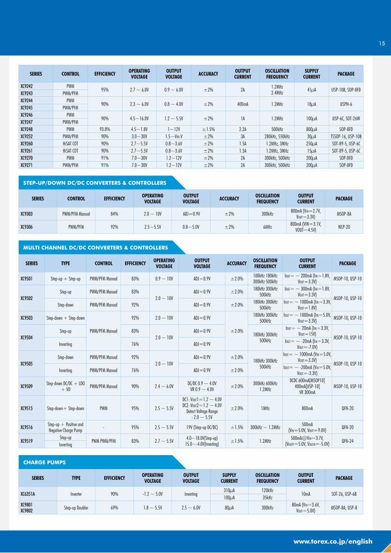
SERIES CONTROL EFFICIENCY OPERATING VOLTAGE
OUTPUTVOLTAGE ACCURACY OUTPUT
CURRENTOSCILLATION FREQUENCY
SUPPLYCURRENT PACKAGE
XC9242 PWM95% 2.7 ~ 6.0V 0.9 ~ 6.0V ±2% 2A 1.2MHz
2.4MHz 41μA USP-10B, SOP-8FDXC9243 PWM/PFMXC9244 PWM
90% 2.3 ~ 6.0V 0.8 ~ 4.0V ±2% 400mA 1.2MHz 18μA USPN-6XC9245 PWM/PFMXC9246 PWM
90% 4.5~16.0V 1.2 ~ 5.5V ±2% 1A 1.2MHz 100μA USP-6C, SOT-26WXC9247 PWM/PFMXC9248 PWM 93.8% 4.5~1.8V 1~12V ±1.5% 2.2A 500kHz 800μA SOP-8FDXC9252 PWM/PFM 90% 3.0~30V 1.5~Vin V ±2% 3A 280kHz, 550kHz 30μA TSSOP-16, USP-10BXC9260 HiSAT COT 90% 2.7~5.5V 0.8~3.6V ±2% 1.5A 1.2MHz, 3MHz 250μA SOT-89-5, USP-6CXC9261 HiSAT COT 90% 2.7~5.5V 0.8~3.6V ±2% 1.5A 1.2MHz, 3MHz 15μA SOT-89-5, USP-6CXC9270 PWM 91% 7.0~30V 1.2~12V ±2% 2A 300kHz, 500kHz 200μA SOP-8FDXC9271 PWM/PFM 91% 7.0~30V 1.2~12V ±2% 2A 300kHz, 500kHz 200μA SOP-8FD
STEP-UP/DOWN DC/DC CONVERTERS & CONTROLLERS
SERIES CONTROL EFFICIENCY OPERATING VOLTAGE
OUTPUTVOLTAGE ACCURACY OSCILLATION
FREQUENCYOUTPUTCURRENT PACKAGE
XC9303 PWM/PFM Manual 84% 2.0 ~ 10V ADJ=0.9V ±2% 300kHz 800mA (VIN=2.7V, VOUT=3.3V) MSOP-8A
XC9306 PWM/PFM 92% 2.5~5.5V 0.8~5.0V ±2% 6MHz 800mA (VIN=3.1V, VOUT=4.5V) WLP-20
MULTI CHANNEL DC/DC CONVERTERS & CONTROLLERS
SERIES TYPE CONTROL EFFICIENCY OPERATING VOLTAGE
OUTPUTVOLTAGE ACCURACY OSCILLATION
FREQUENCYOUTPUTCURRENT PACKAGE
XC9501 Step-up + Step-up PWM/PFM Manual 83% 0.9 ~ 10V ADJ=0.9V ±2.0% 100kHz 180kHz 300kHz 500kHz
IOUT= ~ 200mA (IIN=1.8V, VOUT=3.3V) MSOP-10, USP-10
XC9502Step-up PWM/PFM Manual 83%
2.0 ~ 10VADJ=0.9V ±2.0% 180kHz 300kHz
500kHzIOUT= ~ 300mA (IIN=1.8V,
VOUT=3.3V)MSOP-10, USP-10
Step-down PWM/PFM Manual 92% ADJ=0.9V ±2.0% 180kHz 300kHz 500kHz
IOUT= ~ 1000mA (IIN=3.3V, VOUT=1.8V)
XC9503 Step-down + Step-down
PWM/PFM Manual
92% 2.0 ~ 10V ADJ=0.9V
±2.0%
180kHz 300kHz 500kHz
IOUT= ~ 1000mA (IIN=5.0V, VOUT=3.3V) MSOP-10, USP-10
XC9504Step-up 83%
2.0 ~ 10VADJ=0.9V
180kHz 300kHz 500kHz
IOUT= ~ 20mA (IIN=3.3V, VOUT=15V)
MSOP-10, USP-10Inverting 76% ADJ=0.9V IOUT= ~ -20mA (IIN=3.3V,
VOUT=-7.0V)
XC9505Step-down PWM/PFM Manual 92%
2.0 ~ 10VADJ=0.9V ±2.0%
180kHz 300kHz 500kHz
IOUT= ~ 1000mA (VIN=5.0V, VOUT=3.3V)
MSOP-10, USP-10Inverting PWM/PFM Manual 76% ADJ=0.9V ±2.0% IOUT= ~ -200mA (VIN=5.0V,
VOUT=-3.3V)
XC9509 Step-down DC/DC + LDO + VD PWM/PFM Manual 90% 2.4 ~ 6.0V DC/DC 0.9 ~ 4.0V
VR 0.9 ~ 4.0V ±2.0% 300kHz 600kHz 1.2MHz
DCDC 600mA[MSOP10] 400mA[USP-10]
VR 300mAMSOP-10, USP-10
XC9515 Step-down+ Step-down PWM 95% 2.5 ~ 5.5V
DC1: VOUT1=1.2 ~ 4.0V DC2: VOUT2=1.2 ~ 4.0V
Detect Voltage Range : 2.0 ~ 5.5V
±2.0% 1MHz 800mA QFN-20
XC9516 Step-up + Positive and Negative Charge Pump - 95% 2.5 ~ 5.5V 19V (Step-up DC/DC) ±1.5% 300kHz ~ 1.2MHz 500mA
(VIN=5.0V, VOUT=9.0V) QFN-20
XC9519Step-up
PWM PWM/PFM 83% 2.7 ~ 5.5V 4.0~18.0V(Step-up)15.0~-4.0V(Inverting) ±1.5% 1.2MHz 500mA@VIN=3.7V,
(VOUTP=5.0V, VOUTN=-5.0V) QFN-24Inverting
CHARGE PUMPS
SERIES TYPE EFFICIENCY OPERATING VOLTAGE
OUTPUTVOLTAGE
SUPPLYCURRENT
OSCILLATION FREQUENCY
OUTPUTCURRENT PACKAGE
XC6351A Inverter 90% -1.2 ~ 5.0V Inverting310μA 120kHz
10mA SOT-26, USP-6B100μA 35kHz
XC9801XC9802 Step-up Doubler 69% 1.8 ~ 5.5V 2.5 ~ 6.0V 80μA 300kHz 80mA (VIN=3.6V,
VOUT=5.0V) MSOP-8A, USP-8
16
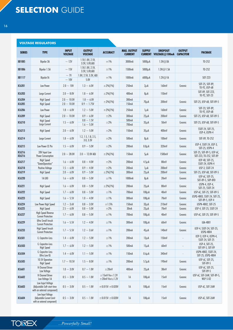
SELECTION GUIDE
VOLTAGE REGULATORS
SERIES TYPE INPUT VOLTAGE
OUTPUT VOLTAGE ACCURACY MAX. OUTPUT
CURRENTSUPPLY
CURRENTDROPOUT
VOLTAGE@100mAOUTPUT
CAPACITOR PACKAGE
XB1085 Bipolar 3A ~ 12V 1.5V,1.8V, 2.5V,3.3V, 5.0V,ADJ ±1% 3000mA 5000μA 1.3V@3A TO-252
XB1086 Bipolar 1.5A ~ 15V 1.5V,1.8V, 2.5V,3.3V, 5.0V,ADJ ±1% 1500mA 5000μA [email protected] TO-252
XB1117 Bipolar1A ~ 7V 1.8V, 2.5V, 3.3V, ADJ
±1% 1000mA 6000μA 1.2V@1A SOT-223 ~ 10V 5.0V
XC6201 Low Power 2.0 ~ 10V 1.3 ~ 6.0V ±2%(1%) 250mA 2μA 160mV Ceramic SOT-25, SOT-89, TO-92, USP-6B
XC6203 Large Current 2.0 ~ 8.0V 1.8 ~ 6.0V ±2%(1%) 400mA 8μA 150mV SOT-89, SOT-223, TO-92, SOT-23
XC6204 High Speed 2.0 ~ 10.0V 1.8 ~ 6.0V ±2%(1%)
300mA70μA 200mV Ceramic SOT-25, USP-6B, SOT-89-5
XC6205 High Speed 2.0 ~ 10.0V 0.9 ~ 1.75V 150mA
XC6206 Low Power 1.8 ~ 6.0V 1.2 ~ 5.0V ±2%(1%) 250mA 1μA 160mV Ceramic SOT-23, SOT-89, TO-92, USP-6B
XC6209 High Speed 2.0 ~ 10.0V 0.9 ~ 6.0V ±2% 300mA 25μA 200mV Ceramic SOT-25, USP-6B, SOT-89-5
XC6210 High Speed Large Current 1.5 ~ 6.0V
0.8 ~ 1.5V±2%
500mA35μA 50mV Ceramic SOT-25, USP-6B, SOT-89-5
1.6 ~ 5.0V 700mA
XC6213 High Speed 2.0 ~ 6.0V 1.2 ~ 5.0V ±2% 150mA 35μA 400mV Ceramic SSOT-24, SOT-25,USP-4, USPN-4
XC6214 Large Current 1.8 ~ 6.0V 1.2, 1.5, 1.8, 2.5, 3.0, 3.3V ±2% 500mA 8μA 100mV Ceramic SOT-89, TO-252
XC6215 Low Power CE Pin 1.5 ~ 6.0V 0.9 ~ 5.0V ±2% 200mA 0.8μA 320mV Ceramic USP-4, SSOT-24, USP-3, SOT-25, USPN-4
XC6216 XE6216
28V Input Low Power Consumption 2.0 ~ 28.0V 2.0 ~ 12.0V ADJ ±2%(1%) 150mA 5μA 1500mV Ceramic SOT-25, SOT-89-5, USP-6C,
SOT-223, TO-252, SOT-89
XC6217 High Speed “GreenOperation” 1.6 ~ 6.0V 0.8 ~ 4.0V ±2% 200mA 4.5μA 80mV Ceramic USP-4D, SOT-25,
SSOT-24, USPN-4XC6218 Positive Voltage 1.5 ~ 6.0V 0.9 ~ 4.0V ±2% 200mA 1μA 200mV Ceramic USP-3, SSOT-24XC6219 High Speed 2.0 ~ 6.0V 0.9 ~ 5.0V ±2%(1%) 300mA 25μA 200mV Ceramic SOT-25, USP-6B, SOT-89-5
XC6220 1A LDO 1.6 ~ 6.0V 0.8 ~ 5.0V ±1% 1000mA 8μA 20mV Ceramic USP-6C, SOT-25, SOT-89-5, SOP-8FD
XC6221 High Speed 1.6 ~ 6.0V 0.8 ~ 5.0V ±2%(1%) 200mA 25μA 80mV Ceramic USPN-4, USP-4, SOT-25, SSOT-24
XC6222 High Speed 1.7 ~ 6.0V 0.8 ~ 5.0V ±1% 700mA 100μA 40mV Ceramic USP-6C, SOT-25, SOT-89-5
XC6223 High Speed 1.6 ~ 5.5V 1.0 ~ 4.0V ±1% 300mA 100μA 70mV Ceramic USPQ-4B03, SSOT-24, SOT-25, SOT-89-5, USP-4
XC6224 Low Power High Speed 1.2 ~ 3.6V 0.8 ~ 3.0V ±1.5% 150mA 33μA 210mV Ceramic USPN-4B02, SOT-25XC6225 High Speed 2.5 ~ 6.0V 0.8 ~ 5.0V ±2% 30mA 25μA 70mV Ceramic USP-4, SOT-25, SSOT-24
XC6227 High Speed Reverse Current Protection 1.7 ~ 6.0V 0.8 ~ 5.0V ±1% 700mA 100μA 40mV Ceramic USP-6C, SOT-25, SOT-89-5
XC6229 Ultra Small Inrush Current Protection 1.6 ~ 5.5V 1.2 ~ 4.0V ±1% 300mA 100μA 60mV Ceramic LGA-4B01
XC6233 High Speed Inrush Current Protection 1.7 ~ 5.5V 1.2 ~ 3.6V ±1% 200mA 45μA 140mV Ceramic USP-4, SSOT-24, SOT-25,
USPQ-4B04
XC6501 CL Capacitor-Less 1.4 ~ 6.0V 1.2 ~ 5.0V ±1% 200mA 13μA 150mV - USP-3, USP-4, USPN-4, SSOT-24, SOT-25
XC6503 CL Capacitor-Less High Speed 1.7 ~ 6.0V 1.2 ~ 5.0V ±1% 500mA 15μA 60mV - USP-4, SOT-25,
SOT-89-5, SOT-89
XC6504 CL Capacitor-Less Ultra Low IQ 1.4 ~ 6.0V 1.1 ~ 5.0V ±1% 150mA 0.6μA 340mV - USPN-4B02, SSOT-24,
SOT-25, USPQ-4B04
XC6505 10.5V Operation High Speed 1.7 ~ 10.5V 1.5 ~ 8.0V ±1% 200mA 5.5μA 190mV Ceramic USP-6C, SOT-25,
SOT-89-5
XC6601 N Channel Driver Low Voltage 1.0 ~ 3.0V 0.7 ~ 1.8V ±20mV 400mA 25μA 38mV Ceramic USP-6C, SOT-25,
SOT-89-5
XC6602 N Channel Driver Low Voltage 1A 0.5 ~ 3.0V 0.5 ~ 1.8V ±15mV VOU<1.2V
±20mV VOUT≥1.2V 1A 100μA 15mV Ceramic USP-6C, SOT-26W, SOT-89-5, WLP-5-02
XC6603Low Input Voltage
(Adjustable Soft-start time with an external component)
0.5 ~ 3.0V 0.5 ~ 1.8V ±0.015V ±0.020V 1A 100μA 15mV Ceramic USP-6C, SOT-26W
XC6604Low Input Voltage
(Adjustable Current Limit with an external component)
0.5 ~ 3.0V 0.5 ~ 1.8V ±0.015V ±0.020V 1A 100μA 15mV Ceramic USP-6C, SOT-26W
17
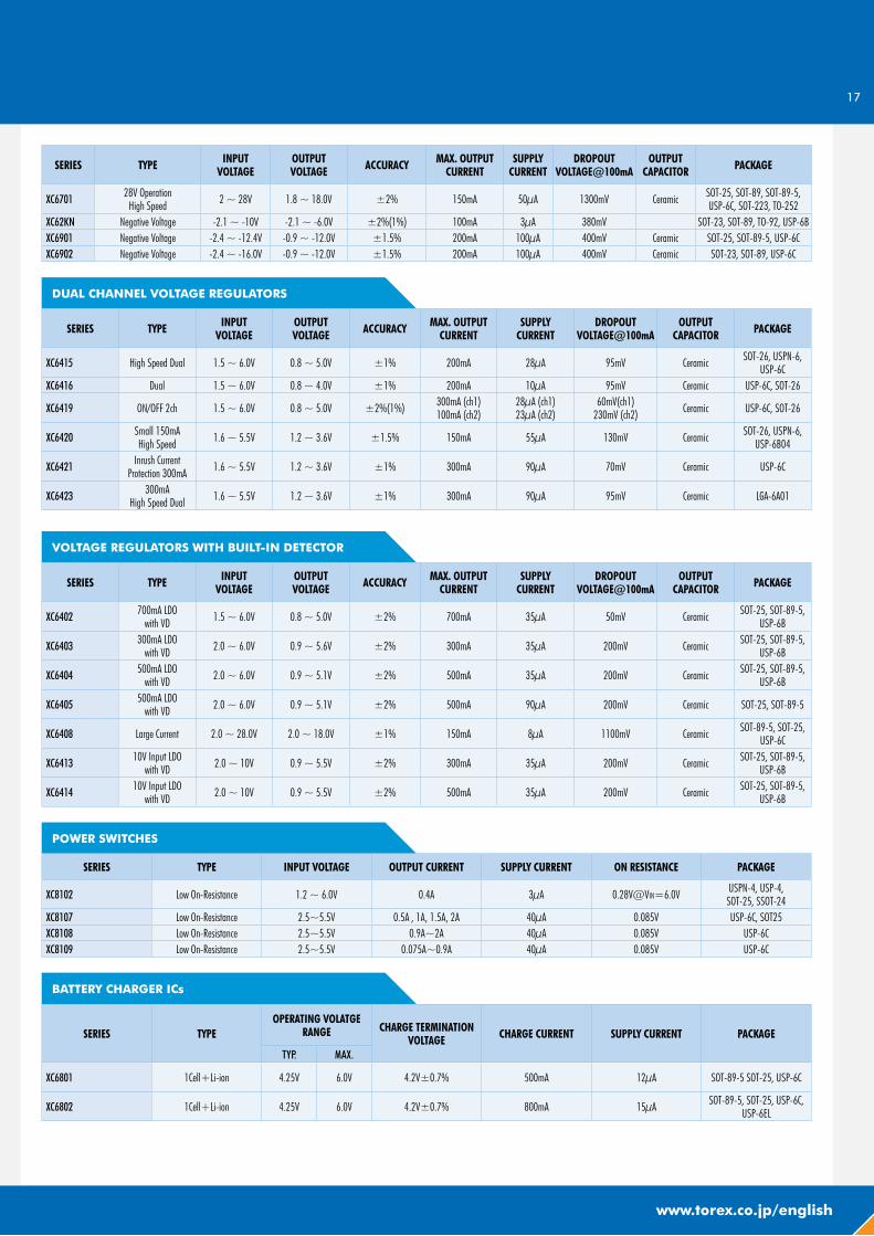
www.torex.co.jp/english
SERIES TYPE INPUT VOLTAGE
OUTPUT VOLTAGE ACCURACY MAX. OUTPUT
CURRENTSUPPLY
CURRENTDROPOUT
VOLTAGE@100mAOUTPUT
CAPACITOR PACKAGE
XC6701 28V Operation High Speed 2 ~ 28V 1.8 ~ 18.0V ±2% 150mA 50μA 1300mV Ceramic SOT-25, SOT-89, SOT-89-5,
USP-6C, SOT-223, TO-252XC62KN Negative Voltage -2.1 ~ -10V -2.1 ~ -6.0V ±2%(1%) 100mA 3μA 380mV SOT-23, SOT-89, TO-92, USP-6BXC6901 Negative Voltage -2.4 ~ -12.4V -0.9 ~ -12.0V ±1.5% 200mA 100μA 400mV Ceramic SOT-25, SOT-89-5, USP-6CXC6902 Negative Voltage -2.4 ~ -16.0V -0.9 ~ -12.0V ±1.5% 200mA 100μA 400mV Ceramic SOT-23, SOT-89, USP-6C
DUAL CHANNEL VOLTAGE REGULATORS
SERIES TYPE INPUTVOLTAGE
OUTPUTVOLTAGE ACCURACY MAX. OUTPUT
CURRENTSUPPLY
CURRENTDROPOUT
VOLTAGE@100mAOUTPUT
CAPACITOR PACKAGE
XC6415 High Speed Dual 1.5 ~ 6.0V 0.8 ~ 5.0V ±1% 200mA 28μA 95mV Ceramic SOT-26, USPN-6, USP-6C
XC6416 Dual 1.5 ~ 6.0V 0.8 ~ 4.0V ±1% 200mA 10μA 95mV Ceramic USP-6C, SOT-26
XC6419 ON/OFF 2ch 1.5 ~ 6.0V 0.8 ~ 5.0V ±2%(1%) 300mA (ch1) 100mA (ch2)
28μA (ch1) 23μA (ch2)
60mV(ch1) 230mV (ch2) Ceramic USP-6C, SOT-26
XC6420 Small 150mA High Speed 1.6 ~ 5.5V 1.2 ~ 3.6V ±1.5% 150mA 55μA 130mV Ceramic SOT-26, USPN-6,
USP-6B04
XC6421 Inrush Current Protection 300mA 1.6 ~ 5.5V 1.2 ~ 3.6V ±1% 300mA 90μA 70mV Ceramic USP-6C
XC6423 300mA High Speed Dual 1.6 ~ 5.5V 1.2 ~ 3.6V ±1% 300mA 90μA 95mV Ceramic LGA-6A01
VOLTAGE REGULATORS WITH BUILT-IN DETECTOR
SERIES TYPE INPUT VOLTAGE
OUTPUT VOLTAGE ACCURACY MAX. OUTPUT
CURRENTSUPPLY
CURRENTDROPOUT
VOLTAGE@100mAOUTPUT
CAPACITOR PACKAGE
XC6402 700mA LDO with VD 1.5 ~ 6.0V 0.8 ~ 5.0V ±2% 700mA 35μA 50mV Ceramic SOT-25, SOT-89-5,
USP-6B
XC6403 300mA LDO with VD 2.0 ~ 6.0V 0.9 ~ 5.6V ±2% 300mA 35μA 200mV Ceramic SOT-25, SOT-89-5,
USP-6B
XC6404 500mA LDO with VD 2.0 ~ 6.0V 0.9 ~ 5.1V ±2% 500mA 35μA 200mV Ceramic SOT-25, SOT-89-5,
USP-6B
XC6405 500mA LDO with VD 2.0 ~ 6.0V 0.9 ~ 5.1V ±2% 500mA 90μA 200mV Ceramic SOT-25, SOT-89-5
XC6408 Large Current 2.0 ~ 28.0V 2.0 ~ 18.0V ±1% 150mA 8μA 1100mV Ceramic SOT-89-5, SOT-25, USP-6C
XC6413 10V Input LDO with VD 2.0 ~ 10V 0.9 ~ 5.5V ±2% 300mA 35μA 200mV Ceramic SOT-25, SOT-89-5,
USP-6B
XC6414 10V Input LDO with VD 2.0 ~ 10V 0.9 ~ 5.5V ±2% 500mA 35μA 200mV Ceramic SOT-25, SOT-89-5,
USP-6B
POWER SWITCHES
SERIES TYPE INPUT VOLTAGE OUTPUT CURRENT SUPPLY CURRENT ON RESISTANCE PACKAGE
XC8102 Low On-Resistance 1.2 ~ 6.0V 0.4A 3μA 0.28V@VIN=6.0V USPN-4, USP-4,SOT-25, SSOT-24
XC8107 Low On-Resistance 2.5~5.5V 0.5A , 1A, 1.5A, 2A 40μA 0.085V USP-6C, SOT25XC8108 Low On-Resistance 2.5~5.5V 0.9A~2A 40μA 0.085V USP-6CXC8109 Low On-Resistance 2.5~5.5V 0.075A~0.9A 40μA 0.085V USP-6C
BATTERY CHARGER ICs
SERIES TYPEOPERATING VOLATGE
RANGE CHARGE TERMINATION VOLTAGE CHARGE CURRENT SUPPLY CURRENT PACKAGE
TYP. MAX.
XC6801 1Cell+Li-ion 4.25V 6.0V 4.2V±0.7% 500mA 12μA SOT-89-5 SOT-25, USP-6C
XC6802 1Cell+Li-ion 4.25V 6.0V 4.2V±0.7% 800mA 15μA SOT-89-5, SOT-25, USP-6C,USP-6EL
18
SELECTION GUIDE
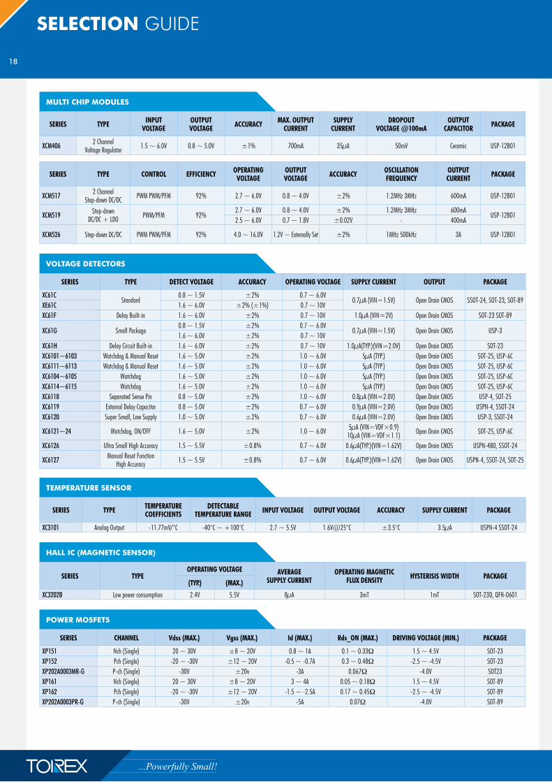
MULTI CHIP MODULES
SERIES TYPE INPUTVOLTAGE
OUTPUTVOLTAGE ACCURACY MAX. OUTPUT
CURRENTSUPPLY
CURRENTDROPOUT
VOLTAGE @100mAOUTPUT
CAPACITOR PACKAGE
XCM406 2 Channel Voltage Regulator 1.5 ~ 6.0V 0.8 ~ 5.0V ±1% 700mA 35μA 50mV Ceramic USP-12B01
SERIES TYPE CONTROL EFFICIENCY OPERATING VOLTAGE
OUTPUT VOLTAGE ACCURACY OSCILLATION
FREQUENCYOUTPUT CURRENT PACKAGE
XCM517 2 Channel Step-down DC/DC PWM PWM/PFM 92% 2.7 ~ 6.0V 0.8 ~ 4.0V ±2% 1.2MHz 3MHz 600mA USP-12B01
XCM519 Step-down DC/DC + LDO PWM/PFM 92%
2.7 ~ 6.0V 0.8 ~ 4.0V ±2% 1.2MHz 3MHz 600mAUSP-12B01
2.5 ~ 6.0V 0.7 ~ 1.8V ±0.02V - 400mA
XCM526 Step-down DC/DC PWM PWM/PFM 92% 4.0 ~ 16.0V 1.2V ~ Externally Set ±2% 1MHz 500kHz 3A USP-12B01
VOLTAGE DETECTORS
SERIES TYPE DETECT VOLTAGE ACCURACY OPERATING VOLTAGE SUPPLY CURRENT OUTPUT PACKAGE
XC61CStandard
0.8 ~ 1.5V ±2% 0.7 ~ 6.0V0.7μA (VIN=1.5V) Open Drain CMOS SSOT-24, SOT-23, SOT-89
XE61C 1.6 ~ 6.0V ±2% (±1%) 0.7 ~ 10VXC61F Delay Built-in 1.6 ~ 6.0V ±2% 0.7 ~ 10V 1.0μA (VIN=2V) Open Drain CMOS SOT-23 SOT-89
XC61G Small Package0.8 ~ 1.5V ±2% 0.7 ~ 6.0V
0.7μA (VIN=1.5V) Open Drain CMOS USP-31.6 ~ 6.0V ±2% 0.7 ~ 10V
XC61H Delay Circuit Built-in 1.6 ~ 6.0V ±2% 0.7 ~ 10V 1.0μA(TYP.)(VIN=2.0V) Open Drain CMOS SOT-23XC6101~6103 Watchdog & Manual Reset 1.6 ~ 5.0V ±2% 1.0 ~ 6.0V 5μA (TYP.) Open Drain CMOS SOT-25, USP-6CXC6111~6113 Watchdog & Manual Reset 1.6 ~ 5.0V ±2% 1.0 ~ 6.0V 5μA (TYP.) Open Drain CMOS SOT-25, USP-6CXC6104~6105 Watchdog 1.6 ~ 5.0V ±2% 1.0 ~ 6.0V 5μA (TYP.) Open Drain CMOS SOT-25, USP-6CXC6114~6115 Watchdog 1.6 ~ 5.0V ±2% 1.0 ~ 6.0V 5μA (TYP.) Open Drain CMOS SOT-25, USP-6CXC6118 Separated Sense Pin 0.8 ~ 5.0V ±2% 1.0 ~ 6.0V 0.8μA (VIN=2.0V) Open Drain CMOS USP-4, SOT-25XC6119 External Delay Capacitor 0.8 ~ 5.0V ±2% 0.7 ~ 6.0V 0.9μA (VIN=2.0V) Open Drain CMOS USPN-4, SSOT-24XC6120 Super Small, Low Supply 1.0 ~ 5.0V ±2% 0.7 ~ 6.0V 0.6μA (VIN=2.0V) Open Drain CMOS USP-3, SSOT-24
XC6121~24 Watchdog, ON/OFF 1.6 ~ 5.0V ±2% 1.0 ~ 6.0V 5μA (VIN=VDF×0.9) 10μA (VIN=VDF×1.1) Open Drain CMOS SOT-25, USP-6C
XC6126 Ultra Small High Accuracy 1.5 ~ 5.5V ±0.8% 0.7 ~ 6.0V 0.6μA(TYP.)(VIN=1.62V) Open Drain CMOS USPN-4B0, SSOT-24
XC6127 Manual Reset Function High Accuracy 1.5 ~ 5.5V ±0.8% 0.7 ~ 6.0V 0.6μA(TYP.)(VIN=1.62V) Open Drain CMOS USPN-4, SSOT-24, SOT-25
TEMPERATURE SENSOR
SERIES TYPE TEMPERATURE COEFFICIENTS
DETECTABLE TEMPERATURE RANGE INPUT VOLTAGE OUTPUT VOLTAGE ACCURACY SUPPLY CURRENT PACKAGE
XC3101 Analog Output -11.77mV/°C -40°C ~ +100°C 2.7 ~ 5.5V 1.6V@25°C ±3.5°C 3.5μA USPN-4 SSOT-24
HALL IC (MAGNETIC SENSOR)
SERIES TYPEOPERATING VOLTAGE AVERAGE
SUPPLY CURRENTOPERATING MAGNETIC
FLUX DENSITY HYSTERISIS WIDTH PACKAGE(TYP.) (MAX.)
XC3202B Low power consumption 2.4V 5.5V 8μA 3mT 1mT SOT-23D, QFN-0601
POWER MOSFETS
SERIES CHANNEL Vdss (MAX.) Vgss (MAX.) Id (MAX.) Rds_ON (MAX.) DRIVING VOLTAGE (MIN.) PACKAGE
XP151 Nch (Single) 20 ~ 30V ±8 ~ 20V 0.8 ~ 1A 0.1 ~ 0.33� 1.5 ~ 4.5V SOT-23XP152 Pch (Single) -20 ~ -30V ±12 ~ 20V -0.5 ~ -0.7A 0.3 ~ 0.48� -2.5 ~ -4.5V SOT-23XP202A0003MR-G P-ch (Single) -30V ±20v -3A 0.067� -4.0V SOT23XP161 Nch (Single) 20 ~ 30V ±8 ~ 20V 3 ~ 4A 0.05 ~ 0.18� 1.5 ~ 4.5V SOT-89XP162 Pch (Single) -20 ~ -30V ±12 ~ 20V -1.5 ~ -2.5A 0.17 ~ 0.45� -2.5 ~ -4.5V SOT-89XP202A0003PR-G P-ch (Single) -30V ±20v -5A 0.07� -4.0V SOT-89
19
www.torex.co.jp/english
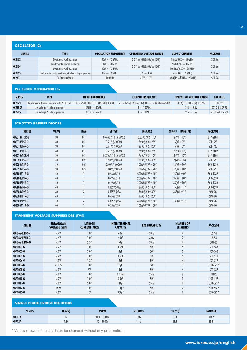
OSCILLATOR ICs
SERIES TYPE OSCILLATION FREQUENCY OPERATING VOLTAGE RANGE SUPPLY CURRENT PACKAGE
XC2163 Overtone crystal oscillator 20M ~ 125MHz 3.3V(±10%) 5.0V(±10%) 15mA(fOSC=120MHz) SOT-26
XC2164Fundamental crystal oscillator 4M ~ 30MHz
3.3V(±10%) 5.0V(±10%)5mA(fOSC =30MHz)
SOT-26Overtone crystal oscillator 20M ~ 125MHz 10.5mA(fOSC=125MHz)
XC2165 Fundamental crystal oscillator with low voltage operation 8M ~ 120MHz 1.5 ~ 3.6V 5mA(fOSC=70MHz) SOT-26XC2301 Tri-State Buffer IC 160MHz 3.3V±10% 13mA(fIN=fOUT=160MHz) SOT-26
PLL CLOCK GENERATOR ICs
SERIES TYPE INPUT FREQUENCY OUTPUT FREQUENCY OPERATING VOLTAGE RANGE PACKAGE
XC2173 Fundamental Crystal Oscillator with PLL Circuit 10 ~ 25MHz (OSCILLATION FREQUENCY) 50 ~ 125MHz(VDD=3.3V), 80 ~ 160MHz(VDD=5.0V) 3.3V(±10%) 5.0V(±10%) SOT-26XC25BS7 Low voltage PLL clock generator 32kHz ~ 30MHz 1 ~ 100MHz 2.5 ~ 5.5V SOT-25, USP-6CXC25BS8 Low Voltage PLL clock generator 8kHz ~ 36MHz 1 ~ 100MHz 2.5 ~ 5.5V SOT-26W, USP-6C
SCHOTTKY BARRIER DIODES
SERIES VR(V) IF(A) VF(TYP.) IR(MAX.) CT@,F=1MHZ(PF) PACKAGE
XBS013R1DR-G 30 0.1 0.46V@10mA (MAX.) 0.3μA@VR=10V 2 (VR=10V) USP-2B01XBS013S15R-G 30 0.1 0.71V@100mA 2μA@VR=25V 6(VR=0V) SOD-523XBS013S16R-G 30 0.1 0.71V@100mA 2μA@VR=25V 6(VR=0V) SOD-723XBS013S1CR-G 30 0.1 0.71V@100mA 2μA@VR=25V 2 (VR=10V) USP-2B02XBS013V1DR-G 30 0.1 0.37V@10mA (MAX.) 7μA@VR=10V 2 (VR=10V) USP-2B01XBS024S15R-G 40 0.2 0.53V@200mA 2μA@VR=40V 5(VR=10V) SOD-523XBS053V13R-G 30 0.5 0.40V@500mA 100μA@VR=20V 12(VR=10V) SOD-323AXBS053V15R-G 30 0.5 0.40V@500mA 100μA@VR=20V 12(VR=10V) SOD-523XBS104P11R-G 40 1 0.56V@1A 500μA@VR=40V 230(VR=0V) SOD-123PXBS104S13R-G 40 1 0.49V@1A 200μA@VR=40V 35(VR=10V) SOD-323AXBS104S14R-G 40 1 0.49V@1A 200μA@VR=40V 35(VR=10V) SOD-123AXBS104V14R-G 40 1 0.365V@1A 2mA@VR=40V 150(VR=1V) SOD-123AXBS303V19R-G 30 3 0.355V@3A 3mA@VR=30V 385(VR=1V) SMA-XGXBS304F11R-G 40 1 0.45V@3A 1mA@VR=20V SMA-PGXBS304S19R-G 40 3 0.465V@3A 300μA@VR=40V 180(VR=1V) SMA-XGXBS306P11R-G 60 1 0.75V@3A 100μA@VR=60V SMA-PG
TRANSIENT VOLTAGE SUPPRESSORS (TVS)
SERIES BREAKDOWN VOLTAGE (MIN)
LEAKAGE CURRENT (MAX)
INTER-TERMINAL CAPACITY ESD DURABILITY NUMBER OF
ELEMENTS PACKAGE
XBP06V4E4GR-R 6.4V 1.0V 40pF 30kV 4 USP-4XBP06V4E2HR-G 6.4V 1.0V 40pF 30kV 2 USP-3XBP06V1E4MR-G 6.1V 2.5V 170pF 30kV 4 SOT-25XBP1001-G 6.2V 1.0V 1.2pF 8kV 5 SOT-563XBP1002-G 6.0V 3.0V 1pF 8kV 9 SOT-363XBP1004-G 6.2V 1.0V 1.2pF 8kV 5 SOT-543XBP1006-G 6.0V 1.2V 1pF 8kV 4 SOT-23PXBP1007-G 27.27V 1.0V 3pF 8kV 3 SOD-323PXBP1008-G 6.0V 20V 1pF 8kV 4 SOT-23PXBP1009-G 6.0V 1.0V 0.35pF 25kV 2 DFN2LXBP1010-G 6.2V 1.0V 35pF 8kV 1 SOD-923XBP1011-G 6.0V 5.0V 110pF 25kV 1 SOD-523PXBP1012-G 13.3V 1.0V 100pF 8kV 2 SOD-323PXBP1013-G 6.0V 10V 300pF 25kV 1 SOD-323P
SINGLE PHASE BRIDGE RECTIFIERS
SERIES IF (AV) VRRM VF(MAX) CJ(TYP) PACKAGE
XBR11A 1A 100~1000V 1.0V 10pF MDIPXBR12A 1.5A 50~1000V 1.1V 25pF SDIP
* Values shown in the chart can be changed without any prior notice.
www.torex.co.jp/english
Torex Semiconductor Ltd.3F Syuwa daini Shinkawa Bldg., 1-24-1 Shinkawa, Chuo-Ku, Tokyo 104-0033 JapanTel: +81-3-6222-2851 Fax: +81-3-6222-2892
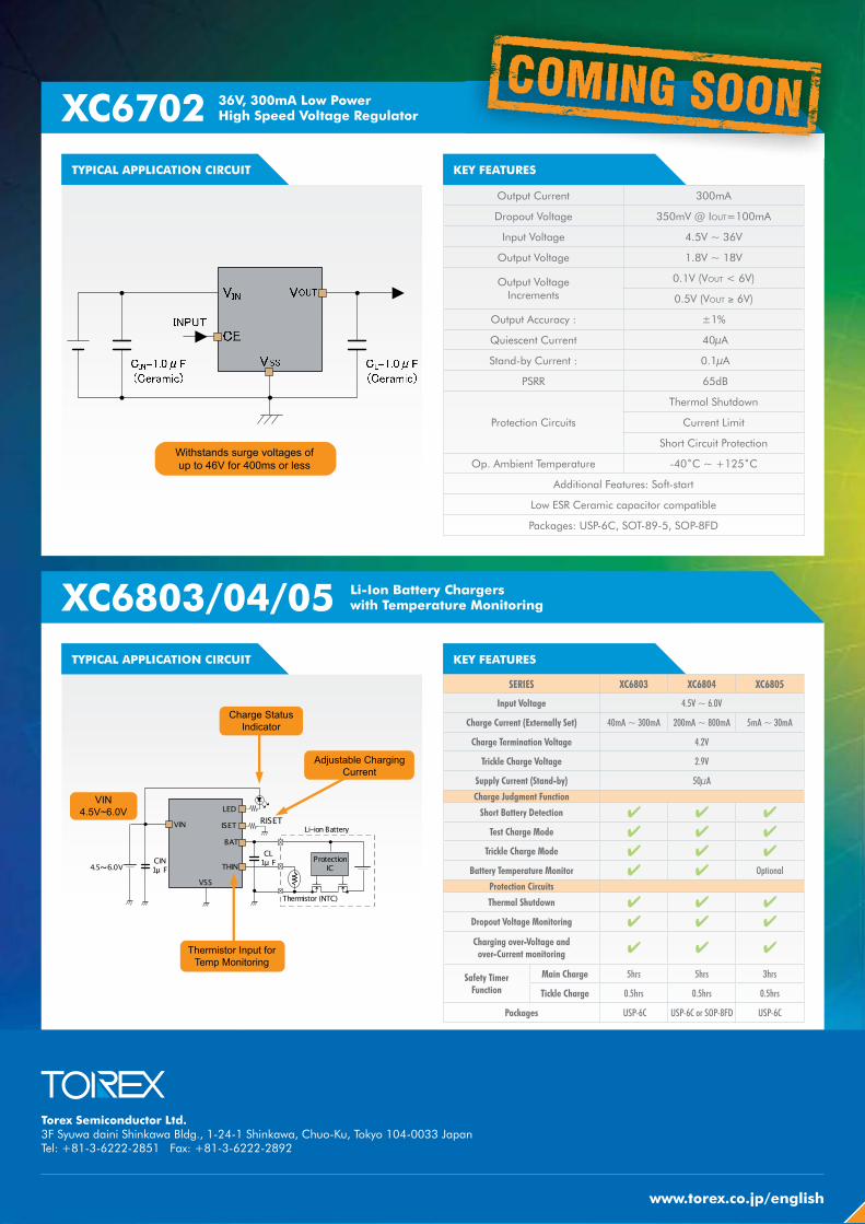
XC6702
XC6803/04/05TYPICAL APPLICATION CIRCUIT
36V, 300mA Low Power High Speed Voltage Regulator
Li-Ion Battery Chargers with Temperature Monitoring
KEY FEATURES
KEY FEATURES
Output Current 300mA
Dropout Voltage 350mV @ IOUT=100mA
Input Voltage 4.5V ~ 36V
Output Voltage 1.8V ~ 18V
Output Voltage Increments
0.1V (VOUT < 6V)
0.5V (VOUT � 6V)
Output Accuracy : ±1%
Quiescent Current 40μA
Stand-by Current : 0.1μA
PSRR 65dB
Protection Circuits
Thermal Shutdown
Current Limit
Short Circuit Protection
Op. Ambient Temperature -40˚C ~ +125˚C
Additional Features: Soft-start
Low ESR Ceramic capacitor compatible
Packages: USP-6C, SOT-89-5, SOP-8FD
SERIES XC6803 XC6804 XC6805
Input Voltage 4.5V ~ 6.0V
Charge Current (Externally Set) 40mA ~ 300mA 200mA ~ 800mA 5mA ~ 30mA
Charge Termination Voltage 4.2V
Trickle Charge Voltage 2.9V
Supply Current (Stand-by) 50μA
Charge Judgment Function
Short Battery Detection � � �
Test Charge Mode � � �
Trickle Charge Mode � � �
Battery Temperature Monitor � � Optional
Protection Circuits
Thermal Shutdown � � �
Dropout Voltage Monitoring � � �
Charging over-Voltage and over-Current monitoring � � �
Safety Timer Function
Main Charge 5hrs 5hrs 3hrs
Tickle Charge 0.5hrs 0.5hrs 0.5hrs
Packages USP-6C USP-6C or SOP-8FD USP-6C
TYPICAL APPLICATION CIRCUIT

![MITSUBISHI ELECTRIC Global website...1.5A/ 6.5 [Power Supply] R61P [CPU] R04CPU RY40NT5P Total Consumption Current 1.5A / 6.5A S V DC 32 / current consumption 1.5A /s_SA /6.5A Az áramfelvétel](https://img.pdfslide.us/doc/110x75/5f36fe787071e7134c12f678/mitsubishi-electric-global-website-15a-65-power-supply-r61p-cpu-r04cpu.jpg)