Embed Size (px)
Citation preview
12. SPRINGS, THEIR DESIGN AND CALCULATIONS
12.1. SPRINGS AND THEIR PROPERTIES
Well-functioning springs are one of the most important prerequisites of agood die function. After all, what good is the drawing operation if the partcannot be stripped off the punch because there is not enough spring powerbehind the pressure pad? Or—what kind of parts will emerge from a diewhere the spring stripper is not spring-loaded adequately?
If ample pressure is the absolute basic of a good die operation, then springsare the most vital parts of every die.
12.1.1. Spring Materials
Springs are elements designed to withstand great amounts of deflection andreturn to their original shape and size on its release. To be capable of suchcyclical loading, spring materials must possess very high elastic limits.
Often materials not specifically made for the spring application are utilizedfor that purpose because their elastic limits are within the aboverequirements. Steels of medium-carbon and high-carbon content areconsidered good spring materials. Where a copperbase alloy is required,beryllium copper and phosphor bronze are utilized.
The surface quality of the spring material has a considerable influence on thefunction of a spring, namely, on its strength and fatigue. Where possible, thesurface finish has to be of the highest grade, preferably polished. This isespecially important with closely wound springs, where friction between
SPRINGS, THEIR DESIGN AND CALCULATIONS

single coils may create minute defects in their surface, which subsequentlywill cause the spring to crack. Music wire, the highest-quality springmaterial, is polished, and its surface is almost defect-free.
Of course, the higher quality the material, the more expensive it is. Thedesigner should strive to find the best combination of price versus quality foreach particular job.
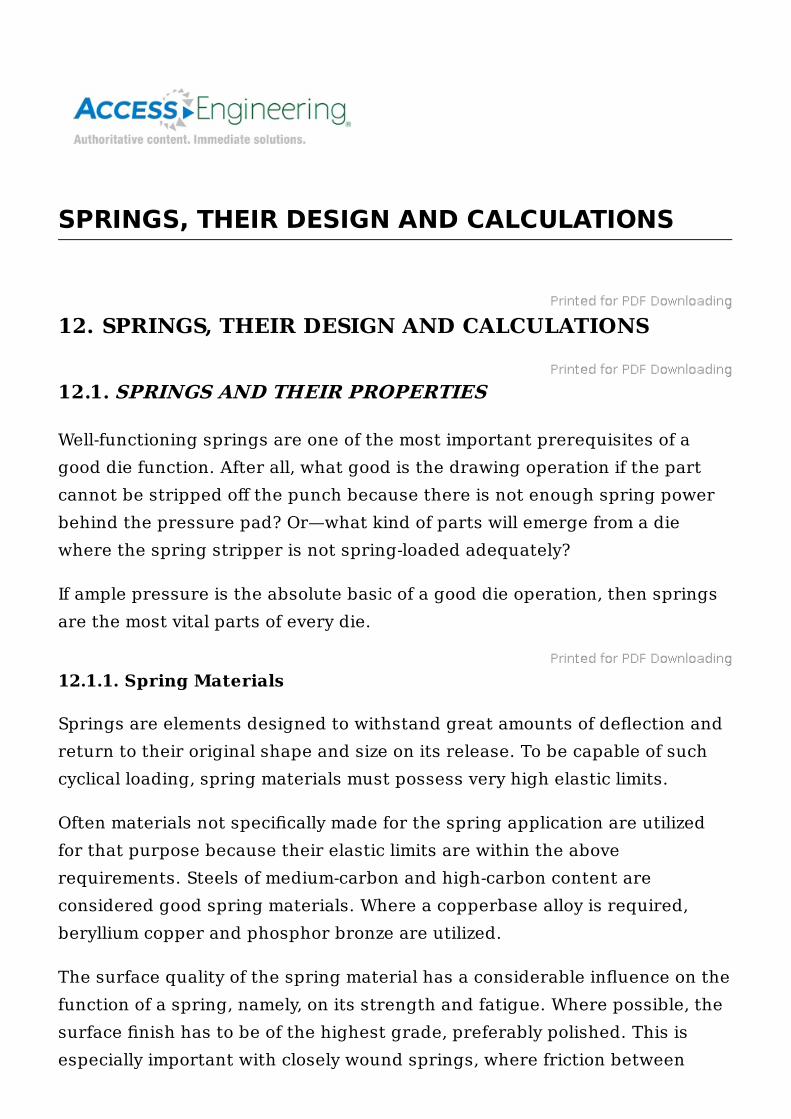
A brief description of basic spring materials is included in Table 12-1, whichprovides a rough comparison of properties, usefulness, and some specificaspects. (Additional properties of spring temper alloy steel are presentedlater in Table 12-8.)
12.1.1.1. HIGH-CARBON SPRING-STEEL WIRE.
This group of spring materials is lowest in cost, which may account for itswidespread use. It does not take impact loading or shock treatment well. Alsoit should not be used in extreme temperatures, high or low. Mainrepresentatives of this group are listed, with the percent of carbon (C) given.
Music wire, ASTM A228 (0.80 to 0.95 percent C). Good for high stressescaused by cyclic repeated loading. A high-tensile-strength material, availableas (cadmium or tin) preplated.
Figure . TABLE 12-1 Typical Properties of Common Spring Materials
Oil-tempered MB grade, ASTM A229 (0.60 to 0.70 percent C). A general-purpose spring steel, frequently used in coiled form. It is not good with shockor impact loading. Can be formed in annealed condition and hardened byheat treatment. Forms a scale, which must be removed if the material isplated.
Hard-drawn MB grade, ASTM A227 (0.60 to 0.70 percent C). Used wherecost is essential. Not to be used where long life and accuracy of loads anddeflections are important. Can be readily plated.
Oil-tempered HB grade, SAE 1080 (0.75 to 0.85 percent C). With theexception of a higher carbon content and higher tensile strength, this spring
Elastic moduli, density, and electrical conductivity can vary withcold work, heat treatment, and operating stress. These varia tionsare usually minor but should be considered if one or more of theseproperties is critical.
Diameters for wire; thicknesses for strip.Typical surface quality ratings. ( For most materials, special
processes can be specified to upgrade typical values. )1. Maximum defect depth: 0 to 0.5% of d or t .2. Maximum defect depth: 1.0% of d or t .3. Defect depth: less than 3.5% of d or t .
Maximum service temperatures are guidelines and may vary owingto operating stress and allowable relaxation.Music and hard drawn are commercial terms for patented and
cold- drawn carbon- steel spring wire.Inconel, Monel, and Ni-Span-C are registered trademarks ofInternational Nickel Company, Inc. BARTEX is a registeredtrademark of Thesis of America, Inc.Source: Design Handbook , 1987. Reprinted with permission fromAssociated Spring, Barnes Group, Inc., Dallas, TX.
a
b
c
d
e
steel is almost the same as the previously described MB grade. It is used formore precise work, where a long life, high fatigue, and high enduranceproperties are needed. If such aspects are not required, an alloy spring steelshould be used in replacement.
12.1.1.2. HIGH-CARBON SPRING-STEEL STRIP.
The two main types of springs steel in this group are used with an absolutemajority of all flat spring. However, both are susceptible to hydrogenembrittlement even when plated and baked afterward.
Cold-rolled blue-tempered spring steel, SAE 1074, plus 1064 and 1070(0.60 to 0.80 percent C). This steel can be obtained in its annealed ortempered condition. Its hardness should be within 42 to 46 Rockwellhardness Scale C.
Cold-rolled, blue-tempered spring steel, SAE 1095 (0.90 to 1.05 percent C).It is not advisable to purchase annealed, as this type of steel does not alwaysharden properly and spring properties obtained after forming may bemarginal. Its hardness range is 47 to 51 Rockwell hardness Scale C.
12.1.1.3. ALLOY SPRING STEEL.
A good spring steel for a high-stress application, with impact loading andshock application involved.
Chromium vanadium steel, ASTM A231 takes higher stresses than high-carbon steel. It also has a good fatigue strength and endurance.
Chromium silicon steel, ASTM A401. This material can be groomed to hightensile stress through heat treatment. Applicable where long life is requiredin combination with shock loading.
12.1.1.4. STAINLESS SPRING STEEL.
A corrosion-resistant material. With the exception of the 18-8 type, none ofthese steels should be used for lower-than-zero temperature applications.High-temperature tolerance is up to 550°F.
Stainless spring steel 302, ASTM A313 (18 percent Cr, 8 percent Ni). This
material has quite uniform properties and the highest tensile strength of thegroup. It can be obtained as cold drawn, since it cannot be hardened by heattreatment. The slight magnetic properties are due to cold working, as inannealed form it is nonmagnetic.
Stainless spring steel 304, ASTM A313 (18 percent Cr, 8 percent Ni).Because of its slightly lower carbon content, this material is easier to draw.Its tensile strength is somewhat lower than that of type 302, even thoughtheir other properties coincide.
Stainless spring steel 316, ASTM A313 (18 percent Cr, 12 percent Ni, 2percent Mo). Less corrosion-prone than the 302 type stainless, with itstensile strength about 12 percent lower. Otherwise it is quite similar to the302 type.
Stainless spring steel 17-7 PH, ASTM A313 (17 percent Cr, 7 percent Ni,with trace amounts of aluminum and titanium). The tensile strength of thismaterial is almost as high as that of music wire. This is achieved throughforming in a medium hard condition and precipitation hardening at lowtemperatures.
Stainless spring steel 414, SAE 51414 (12 percent Cr, 2 percent Ni). Itstensile strength is approximately the same as that of type 316 (above), and itmay be hardened through heat treatment. In a high-polished condition thismaterial resists corrosion quite well.
Stainless spring steel 420, SAE 51420 (13 percent Cr). May be obtained inthe annealed state, hardened and tempered. Scales in heat treatment. Itscorrosion-resistant properties emerge only after hardening. Clear brightsurface finish enhances its corrosion resistance.
Stainless spring steel 431, SAE 51431 (16 percent Cr, 2 percent Ni). Thismaterial has very high tensile properties, almost on a par with music wire.Such a characteristic is achieved through a combination of heat treatment,followed by cold working.
12.1.1.5. COPPER-BASE SPRING ALLOYS.
This group of spring materials is more expensive than alloy steels or high-carbon materials. They are, however, very useful for their good corrosion
resistance and superb electrical properties. An additional advantage is theirusefulness in lower-than-zero temperatures.
Spring brass, ASTM B134 (70 percent Cu, 30 percent Zn) cannot behardened by heat treatment and has generally quite poor spring qualities.Even though it does not tolerate temperatures higher than 150°F, it performswell at subzero. It is the least expensive copperbase spring material, with thehighest electrical conductivity, out-weighed by its low tensile strength.
Phosphor bronze (a tin bronze), ASTM B159 (95 percent Cu, 5 percent Sn).This is the most popular copper-based spring material. Its popularity is dueto its favorable combination of electrical conductivity, corrosion resistance,good tensile strength, hardness, and low cost.
Beryllium copper, ASTM B197 (98 percent Cu, 2 percent Be) is the mostexpensive material of this group. It is better formed in its annealed conditionand precipitation hardened afterward. The hardened material turns brittleand does not take additional forming. The material has a high hardness andtensile strength. It is used where electrical conductivity is of importance.
12.1.1.6. NICKEL-BASE SPRING ALLOYS.
These alloys take both extremes in temperature, extremely hot and extremelycold, while being corrosion-resistant. For their high resistance to electricitythe materials should not be used with electric current. Their field ofapplication lies with precise measuring instruments such as gyroscopes.
Monel (67 percent Ni, 30 percent Cu) cannot be hardened by heat treatment.Its high tensile strength and hardness is obtained through cold drawing andcold rolling. It is almost nonmagnetic and withstands stresses comparable tothose beryllium copper can handle. It is the least expensive material of thisgroup.
K-Monel (66 percent Ni, 29 percent Cu, 6 percent Al). The material isnonmagnetic, and the small amount of aluminum makes it a precipitation-hardening applicant. Otherwise it is very similar to previously describedmonel. It can be formed soft and hardened afterward by application of anage-hardening heat treatment.
Inconel (78 percent Ni, 14 percent Cr, 7 percent Fe) has higher tensile
strength and hardness than K-monel, both of these properties beingattributable to cold drawing and cold rolling, as it cannot be hardened byheat treatment. It can be used at temperatures of up to 700°F. It is a verypopular alloy because of its corrosion resistance, even though its cost ishigher than that of the stainless-steel group, yet not so costly as berylliumcopper.
Inconel-X (70 percent Ni, 16 percent Cr, 7 percent Fe, with small amounts oftitanium, columbium, and aluminum). This nonmagnetic material should beprecipitation hardened at high temperatures. It is operable up to 850°F.
Duranickel (98 percent Ni) takes slightly lower temperatures than inconel. Itis non-magnetic, resistant to corrosion, and has a high tensile strength. Itcan be precipitation hardened.
12.1.2. Heat Treatment of Springs
Heat treatment of finished springs is done in two stages. First, following theforming process, a low-temperature heat treatment of 350 to 950°F (175 to510°C) is applied. Such a treatment causes the material to stabilizedimensionally, while removing some residual stresses developed during theforming operation. Residual stresses come in two groups: Some of them arebeneficial to the part’s functionality; others are detrimental to it.
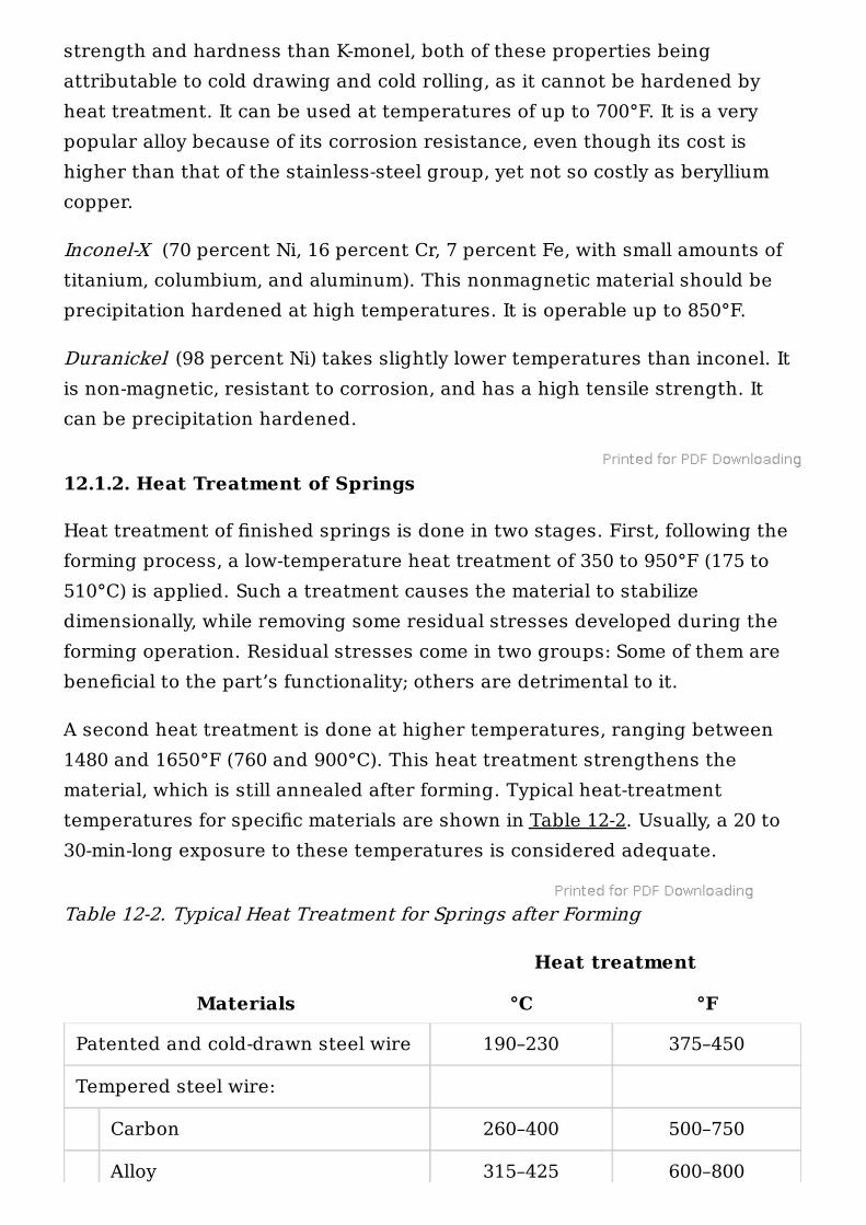
A second heat treatment is done at higher temperatures, ranging between1480 and 1650°F (760 and 900°C). This heat treatment strengthens thematerial, which is still annealed after forming. Typical heat-treatmenttemperatures for specific materials are shown in Table 12-2. Usually, a 20 to30-min-long exposure to these temperatures is considered adequate.
Table 12-2. Typical Heat Treatment for Springs after Forming
Heat treatment
Materials °C °F
Patented and cold-drawn steel wire 190–230 375–450
Tempered steel wire:
Carbon 260–400 500–750
Alloy 315–425 600–800
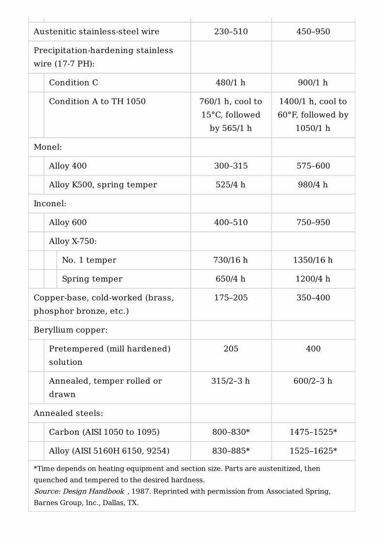
*Time depends on heating equipment and section size. Parts are austenitized, thenquenched and tempered to the desired hardness.Source: Design Handbook , 1987. Reprinted with permission from Associated Spring,Barnes Group, Inc., Dallas, TX.
Austenitic stainless-steel wire 230–510 450–950
Precipitation-hardening stainlesswire (17-7 PH):
Condition C 480/1 h 900/1 h
Condition A to TH 1050 760/1 h, cool to15°C, followed
by 565/1 h
1400/1 h, cool to60°F, followed by
1050/1 h
Monel:
Alloy 400 300–315 575–600
Alloy K500, spring temper 525/4 h 980/4 h
Inconel:
Alloy 600 400–510 750–950
Alloy X-750:
No. 1 temper 730/16 h 1350/16 h
Spring temper 650/4 h 1200/4 h
Copper-base, cold-worked (brass,phosphor bronze, etc.)
175–205 350–400
Beryllium copper:
Pretempered (mill hardened)solution
205 400
Annealed, temper rolled ordrawn
315/2–3 h 600/2–3 h
Annealed steels:
Carbon (AISI 1050 to 1095) 800–830* 1475–1525*
Alloy (AISI 5160H 6150, 9254) 830–885* 1525–1625*
Hardened high-carbon steel parts, when electroplated, are prone to cracking.This is caused by the action of hydrogen atoms, which intermingle with thematerial’s metallic lattice and affect its structure. Such an occurrence iscalled hydrogen embrittlement. To prevent hydrogen embrittlement in platedsprings, heat treatment at low temperatures is used prior to plating, with abaking operation added after forming.
Beryllium copper is strengthened after forming by the application of an age-hardening process; with other materials, tempering may sometimes beutilized.
12.1.3. Corrosion Resistance
Coatings (zinc, cadmium, and their alloys) are frequently utilized to preventcorrosion damage to springs. These coatings not only act as a blockadebetween the material and the outside environment. They also protect thepart cathodically, often even when scratched or otherwise topically damaged.
Electroplating is another method of protection used with application ofmetallic coatings. This type of surface finish, however, causes hydrogenembrittlement to appear, and care should be taken to minimize the part’ssusceptibility. As a means of protection, there should be no stress points inthe part, such as sharp corners, sharp bends, or sharp-cornered cuts.Hardness should be at the minimum allowable level, and residual stresseswithin the material should be relieved by application of the highest possibleheat-treating temperatures. After plating, parts should be baked at lowtemperatures for approximately 2 to 3 h.
Mechanical plating offers an adequate amount of protection againstcorrosion and hydrogen embrittlement as well. Such surface treatmentshould be used for parts suffering from high residual stresses after theforming operation. Its drawback lies in the difficulties with plating of tight orinaccessible areas—all part surfaces must be well exposed and clean.
12.1.4. Fatigue and Reliability
Fatigue in springs is a process that develops slowly and insidiously over thespan of three stages: (1) crack induction, (2) crack increase, and (3) failure ofthe material. It is obvious that fatigue is an irreversible process, detrimental
to the functionability of the part. Its development is caused by theemergence of cyclic stresses, accompanied by plastic strains, so common insprings. It may also be caused by the quenching process during springsmanufacture.
Residual stresses, as found in the spring material after bending, may eitherincrease or diminish its fatigue resistance. This variation in their influence isdue to the fact that there actually are two types of residual stresses withinthe material.
Stresses which counterbalance those accompanying the spring operation arebeneficial to the part’s longevity. For example, in a compressed coil spring,where a residual tension is encountered at its core, some residual stresses ofthe compressive type should ideally be near its surface. A condition like thismay create an environment within the material of the spring, allowing forincreased loads and improving the spring’s resistance to fatigue.
However, if the residual stresses are in another (opposite) direction, theircontribution to the load-carrying capacity and fatigue resistance of thespring will be negative.
Favorable residual stresses are often introduced to the spring material bythe spring manufacturer. After the first stress-relieving heat treatment, aslight plastic deformation is purposely caused to the parts, following thedirection of the spring’s own elastic deformation later in service.Unfortunately, such prestressing cannot be preformed with all springs, as itssubsequent increase in production costs cannot always be justified.
Plated steel springs emerge from the plating operation free from residualstresses, which cannot be reintroduced afterward.
For removal of various residual stresses located near the surface, shotpeening is utilized. This procedure, however, decreases the load-carryingcapacity of the spring, as it lowers the material’s yield strength.
Reliability is a fatigue-dependent value, where the decrease in the spring’sreliability is always caused by defects produced by fatigue.
Reliability of springs operating at higher temperatures is negativelyinfluenced by so-called stress relaxation . It is the decrease in the load-carrying capacity and deflecting capacity of a spring held or cycled under a
load. Higher temperatures also affect the tensile strength, fatigue, andmodulus of the material.
Stresses and high operating temperatures will in time produce stressrelaxation in springs. In opposition to such an influence is the type of alloy:More alloyed materials were found less susceptible to the damage caused bytemperature increases.
In static applications, the load-carrying ability of a spring may be impaired byits yield strength and resistance to stress relaxation. To increase the staticload-carrying capacity, a longer than necessary spring length should beselected and precompressed to solid in assembly. This process is called setremoval or presetting of the spring, and it may increase the load-carryingability by 45 to 65 percent. By presetting the spring, favorable residualstresses are introduced into the material. Their type and directioncorrespond with the spring’s own natural (elastic) deformation, attributableto its function.
12.2. SPRINGS IN DIE DESIGN
Types of springs most often used in die and fixture design are coil springs ofthe compression type. Marginally, extension coil springs and flat springs areutilized.
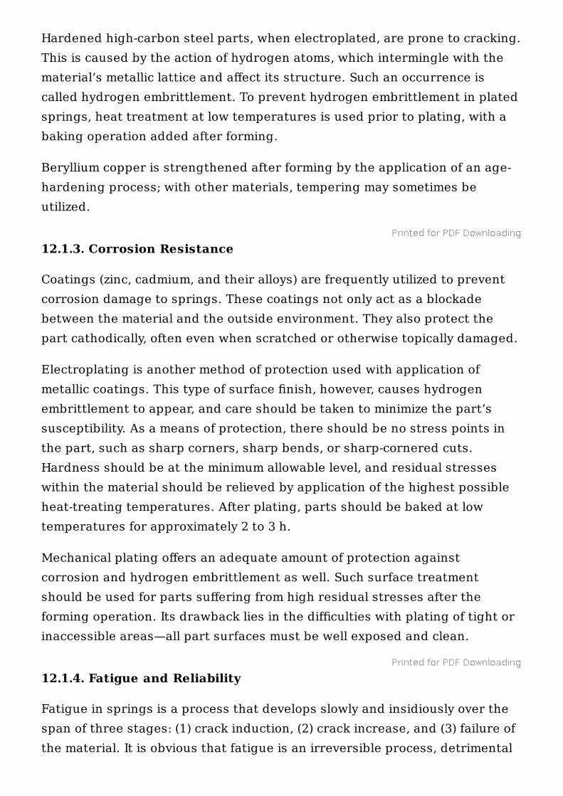
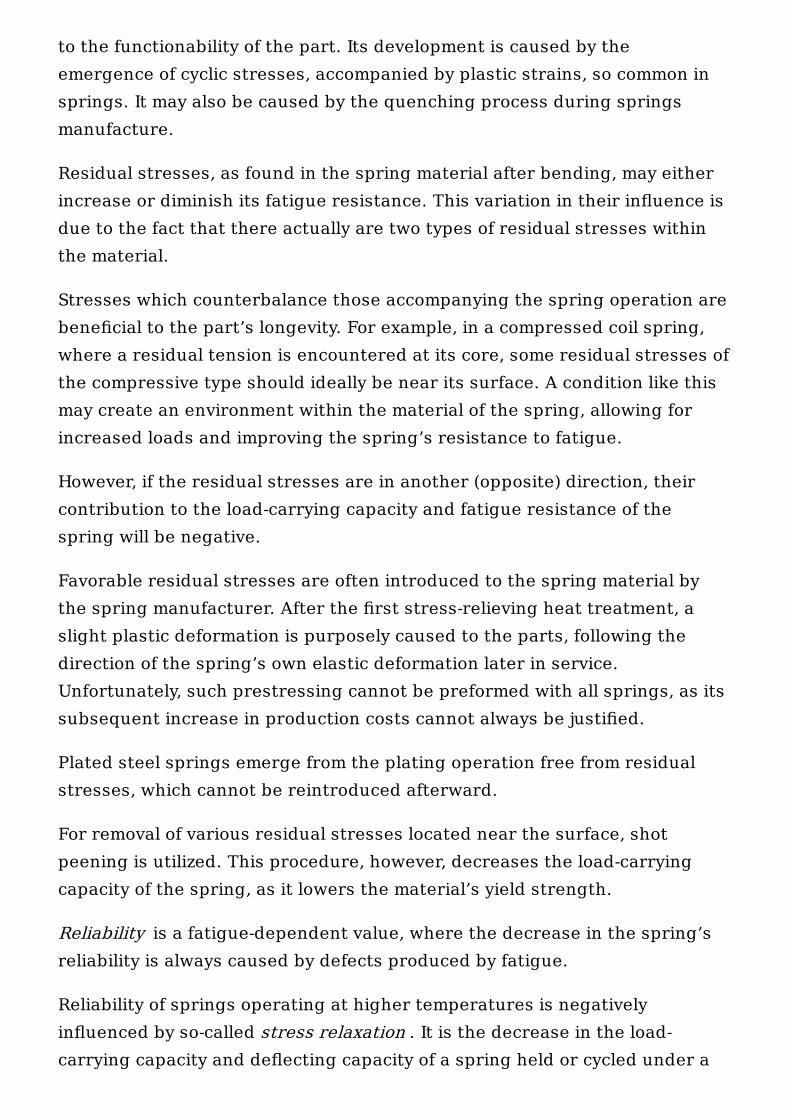
Compression springs are wound as an open helix (Fig. 12-1) with an openpitch to resist the compressive force applied against it. Overall shapes ofthese springs are most often straight and cylindrical. But variations in theoutline and winding, such as barrel-shaped, conical, hourglass, and variable-pitch springs can be encountered (Fig. 12-2).
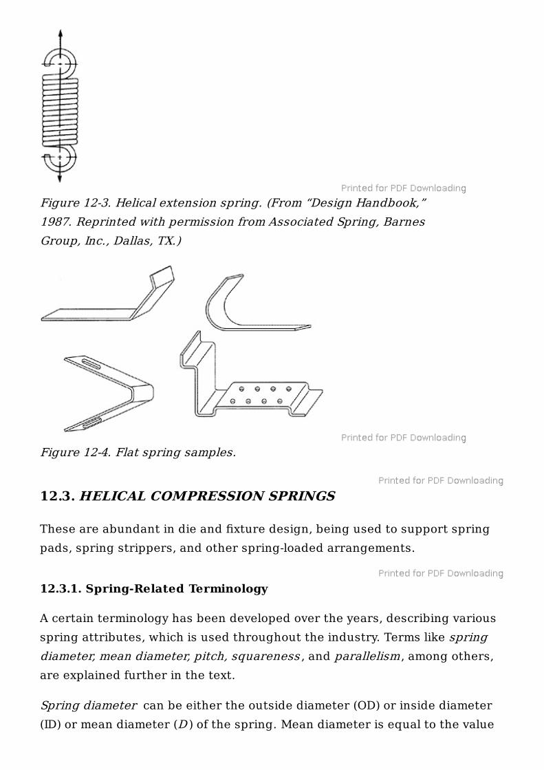
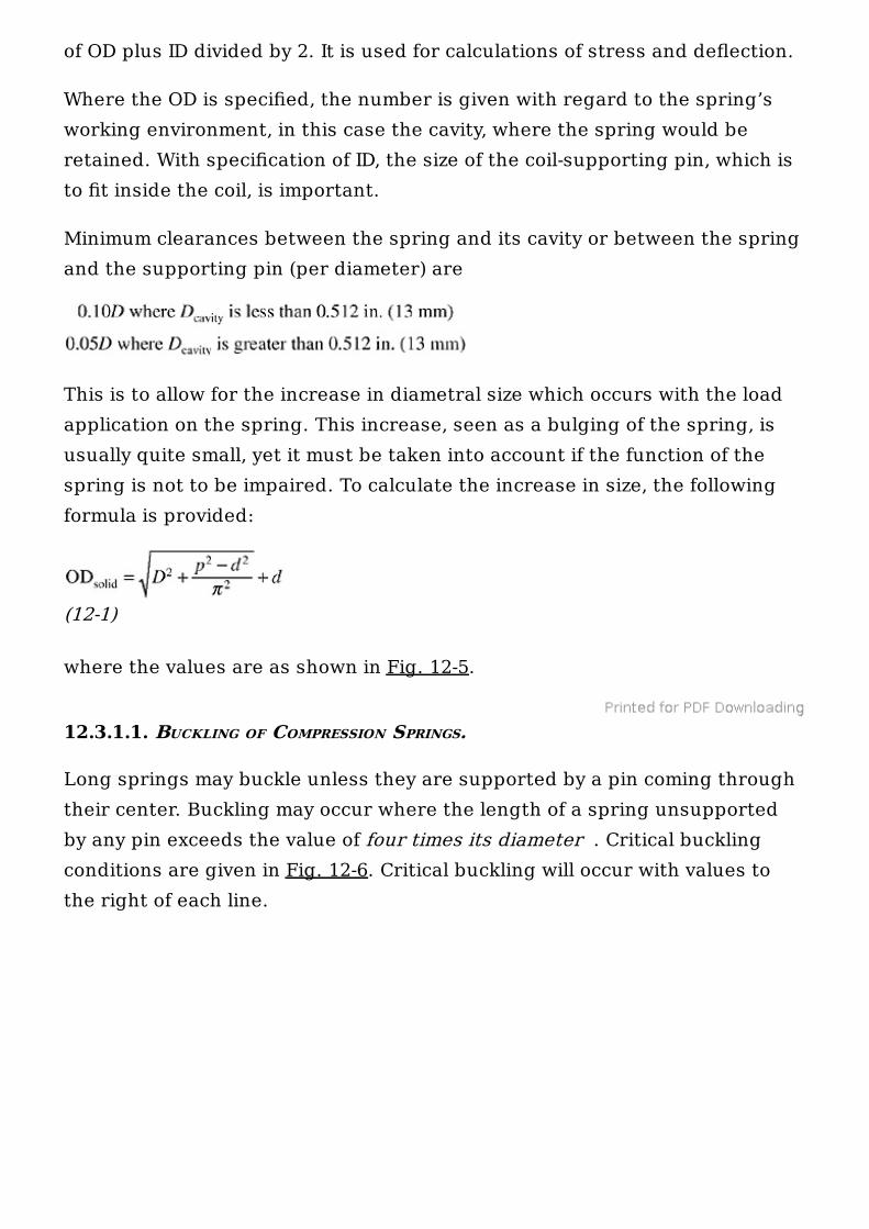
Extension springs form a tight helix, and their pitch is limited to the wirethickness (Fig. 12-3). Flat springs may come in many types and shapes (Fig.12-4).
Figure 12-1. Compression spring and its properties.
Figure 12-2. Helical compression springs, round and rectangularwire. (From “Design Handbook,” 1987. Reprinted with permissionfrom Associated Spring, Barnes Group, Inc., Dallas, TX.)
12.3. HELICAL COMPRESSION SPRINGS
These are abundant in die and fixture design, being used to support springpads, spring strippers, and other spring-loaded arrangements.
12.3.1. Spring-Related Terminology
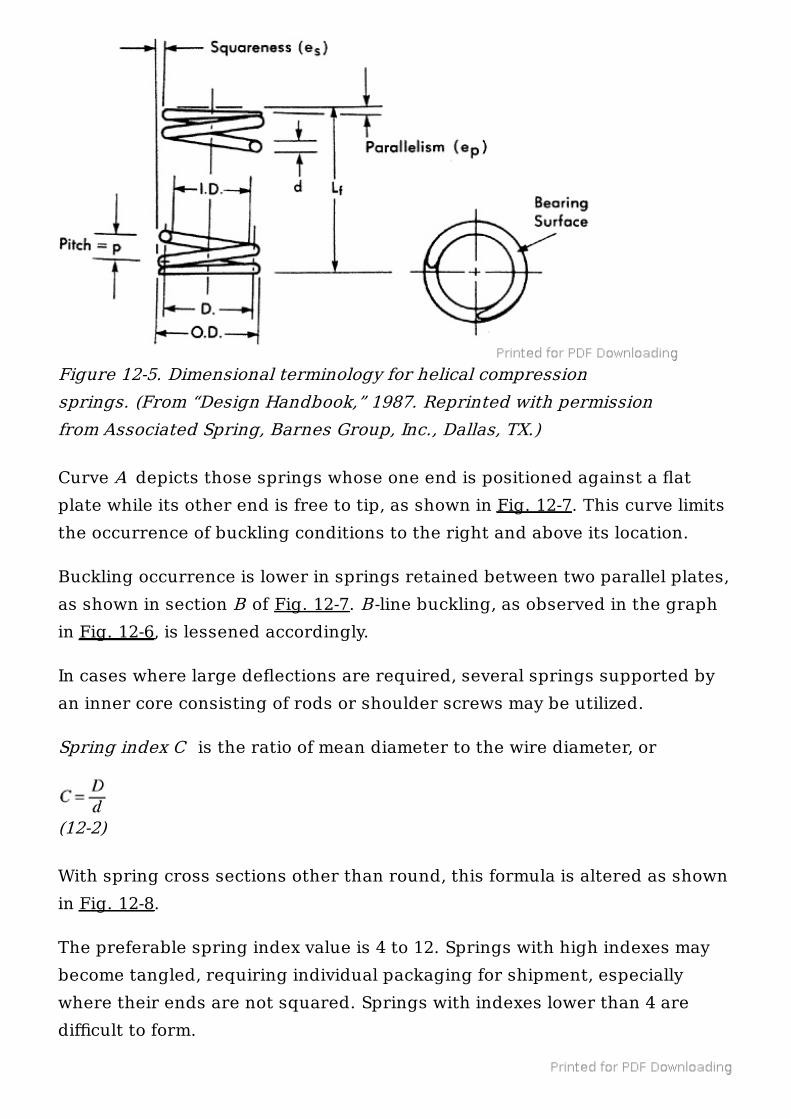
A certain terminology has been developed over the years, describing variousspring attributes, which is used throughout the industry. Terms like springdiameter, mean diameter, pitch, squareness , and parallelism, among others,are explained further in the text.
Spring diameter can be either the outside diameter (OD) or inside diameter(ID) or mean diameter (D ) of the spring. Mean diameter is equal to the value
Figure 12-3. Helical extension spring. (From “Design Handbook,”1987. Reprinted with permission from Associated Spring, BarnesGroup, Inc., Dallas, TX.)
Figure 12-4. Flat spring samples.
of OD plus ID divided by 2. It is used for calculations of stress and deflection.
Where the OD is specified, the number is given with regard to the spring’sworking environment, in this case the cavity, where the spring would beretained. With specification of ID, the size of the coil-supporting pin, which isto fit inside the coil, is important.
Minimum clearances between the spring and its cavity or between the springand the supporting pin (per diameter) are
This is to allow for the increase in diametral size which occurs with the loadapplication on the spring. This increase, seen as a bulging of the spring, isusually quite small, yet it must be taken into account if the function of thespring is not to be impaired. To calculate the increase in size, the followingformula is provided:
(12-1)
where the values are as shown in Fig. 12-5.
12.3.1.1. BUCKLING OF COMPRESSION SPRINGS.
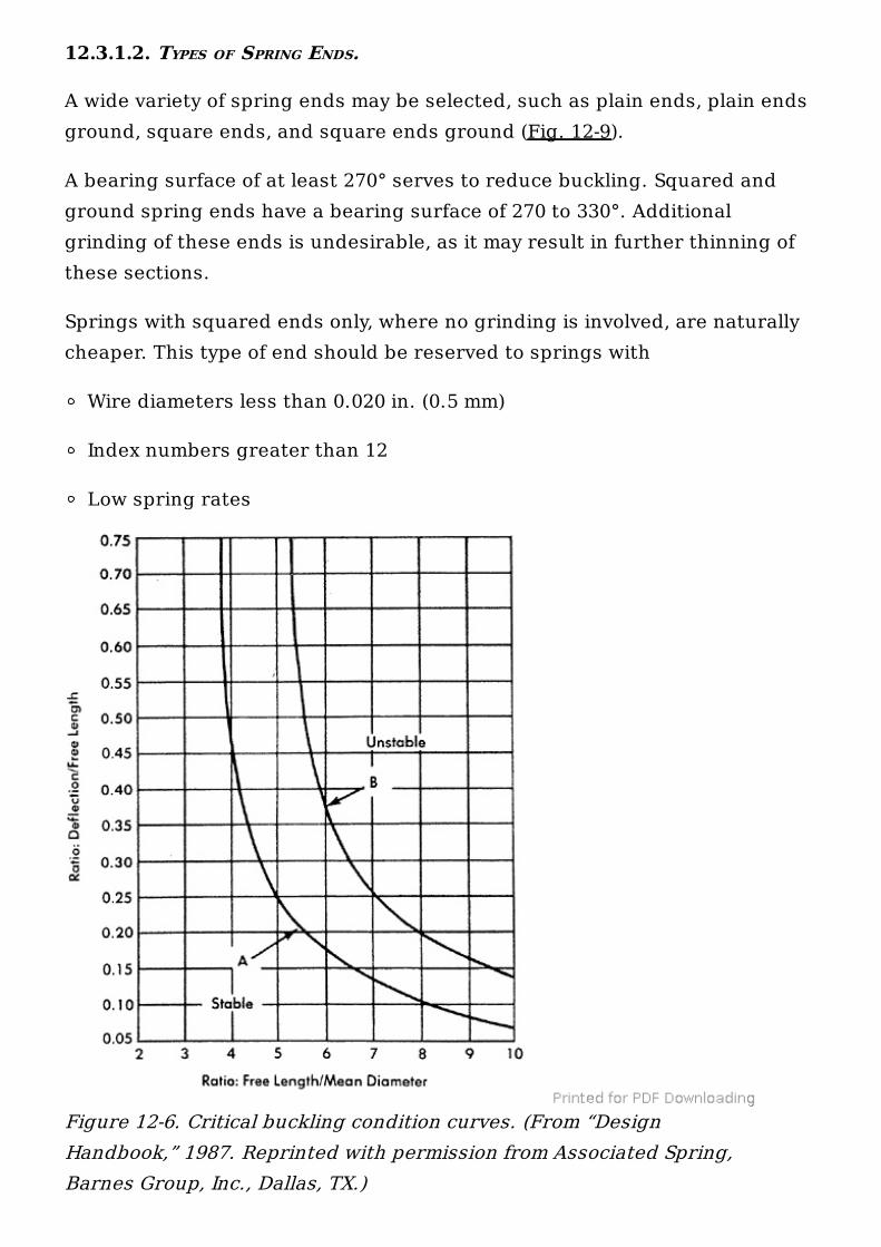
Long springs may buckle unless they are supported by a pin coming throughtheir center. Buckling may occur where the length of a spring unsupportedby any pin exceeds the value of four times its diameter . Critical bucklingconditions are given in Fig. 12-6. Critical buckling will occur with values tothe right of each line.
Curve A depicts those springs whose one end is positioned against a flatplate while its other end is free to tip, as shown in Fig. 12-7. This curve limitsthe occurrence of buckling conditions to the right and above its location.
Buckling occurrence is lower in springs retained between two parallel plates,as shown in section B of Fig. 12-7. B -line buckling, as observed in the graphin Fig. 12-6, is lessened accordingly.
In cases where large deflections are required, several springs supported byan inner core consisting of rods or shoulder screws may be utilized.
Spring index C is the ratio of mean diameter to the wire diameter, or
(12-2)
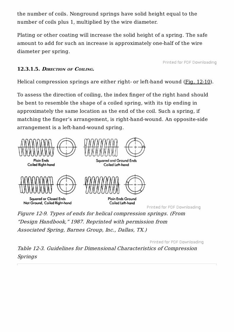
With spring cross sections other than round, this formula is altered as shownin Fig. 12-8.
The preferable spring index value is 4 to 12. Springs with high indexes maybecome tangled, requiring individual packaging for shipment, especiallywhere their ends are not squared. Springs with indexes lower than 4 aredifficult to form.
Figure 12-5. Dimensional terminology for helical compressionsprings. (From “Design Handbook,” 1987. Reprinted with permissionfrom Associated Spring, Barnes Group, Inc., Dallas, TX.)
12.3.1.2. TYPES OF SPRING ENDS.
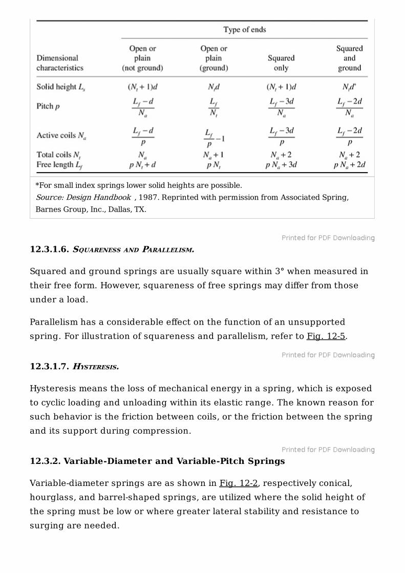
A wide variety of spring ends may be selected, such as plain ends, plain endsground, square ends, and square ends ground (Fig. 12-9).
A bearing surface of at least 270° serves to reduce buckling. Squared andground spring ends have a bearing surface of 270 to 330°. Additionalgrinding of these ends is undesirable, as it may result in further thinning ofthese sections.
Springs with squared ends only, where no grinding is involved, are naturallycheaper. This type of end should be reserved to springs with
Wire diameters less than 0.020 in. (0.5 mm)
Index numbers greater than 12
Low spring rates
Figure 12-6. Critical buckling condition curves. (From “DesignHandbook,” 1987. Reprinted with permission from Associated Spring,Barnes Group, Inc., Dallas, TX.)
12.3.1.3. NUMBER OF ACTIVE COILS N .
Springs with squared ends have the number of active coils approximatelyequal to the total number of coils minus 2. Springs with plain ends usuallyhave more of their coils active, the exact number being dependent on theirseating method. Guidelines for selection of end types for a particular springapplication are given in Table 12-3.
12.3.1.4. SOLID HEIGHT.
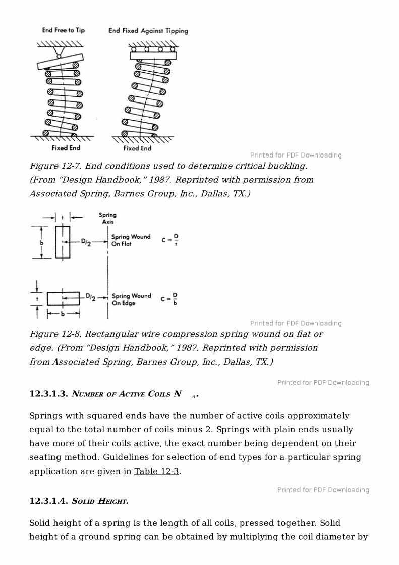
Solid height of a spring is the length of all coils, pressed together. Solidheight of a ground spring can be obtained by multiplying the coil diameter by
Figure 12-7. End conditions used to determine critical buckling.(From “Design Handbook,” 1987. Reprinted with permission fromAssociated Spring, Barnes Group, Inc., Dallas, TX.)
Figure 12-8. Rectangular wire compression spring wound on flat oredge. (From “Design Handbook,” 1987. Reprinted with permissionfrom Associated Spring, Barnes Group, Inc., Dallas, TX.)
A
the number of coils. Nonground springs have solid height equal to thenumber of coils plus 1, multiplied by the wire diameter.
Plating or other coating will increase the solid height of a spring. The safeamount to add for such an increase is approximately one-half of the wirediameter per spring.
12.3.1.5. DIRECTION OF COILING.
Helical compression springs are either right- or left-hand wound (Fig. 12-10).
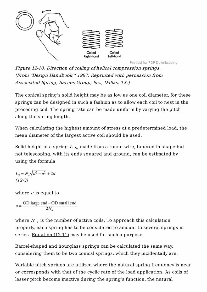
To assess the direction of coiling, the index finger of the right hand shouldbe bent to resemble the shape of a coiled spring, with its tip ending inapproximately the same location as the end of the coil. Such a spring, ifmatching the finger’s arrangement, is right-hand-wound. An opposite-sidearrangement is a left-hand-wound spring.
Table 12-3. Guidelines for Dimensional Characteristics of CompressionSprings
Figure 12-9. Types of ends for helical compression springs. (From“Design Handbook,” 1987. Reprinted with permission fromAssociated Spring, Barnes Group, Inc., Dallas, TX.)
12.3.1.6. SQUARENESS AND PARALLELISM.
Squared and ground springs are usually square within 3° when measured intheir free form. However, squareness of free springs may differ from thoseunder a load.
Parallelism has a considerable effect on the function of an unsupportedspring. For illustration of squareness and parallelism, refer to Fig. 12-5.
12.3.1.7. HYSTERESIS.
Hysteresis means the loss of mechanical energy in a spring, which is exposedto cyclic loading and unloading within its elastic range. The known reason forsuch behavior is the friction between coils, or the friction between the springand its support during compression.
12.3.2. Variable-Diameter and Variable-Pitch Springs
Variable-diameter springs are as shown in Fig. 12-2, respectively conical,hourglass, and barrel-shaped springs, are utilized where the solid height ofthe spring must be low or where greater lateral stability and resistance tosurging are needed.
*For small index springs lower solid heights are possible.Source: Design Handbook , 1987. Reprinted with permission from Associated Spring,Barnes Group, Inc., Dallas, TX.
The conical spring’s solid height may be as low as one coil diameter, for thesesprings can be designed in such a fashion as to allow each coil to nest in thepreceding coil. The spring rate can be made uniform by varying the pitchalong the spring length.
When calculating the highest amount of stress at a predetermined load, themean diameter of the largest active coil should be used.
Solid height of a spring L , made from a round wire, tapered in shape butnot telescoping, with its ends squared and ground, can be estimated byusing the formula
(12-3)
where u is equal to
where N is the number of active coils. To approach this calculationproperly, each spring has to be considered to amount to several springs inseries. Equation (12-11) may be used for such a purpose.
Barrel-shaped and hourglass springs can be calculated the same way,considering them to be two conical springs, which they incidentally are.
Variable-pitch springs are utilized where the natural spring frequency is nearor corresponds with that of the cyclic rate of the load application. As coils oflesser pitch become inactive during the spring’s function, the natural
Figure 12-10. Direction of coiling of helical compression springs.(From “Design Handbook,” 1987. Reprinted with permission fromAssociated Spring, Barnes Group, Inc., Dallas, TX.)
S
a
frequency of the spring will change. This will result in minimizing of surgingand spring resonance. Spring resonance is addressed in Sec. 12-4-6.
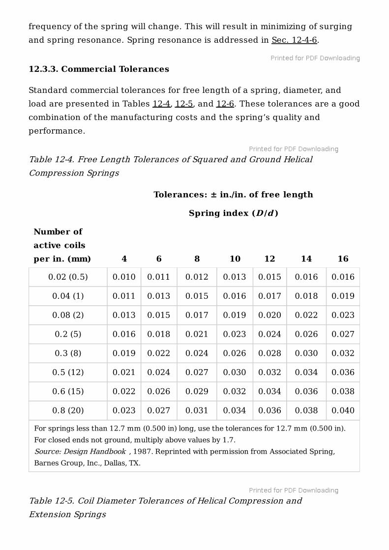
12.3.3. Commercial Tolerances
Standard commercial tolerances for free length of a spring, diameter, andload are presented in Tables 12-4, 12-5, and 12-6. These tolerances are a goodcombination of the manufacturing costs and the spring’s quality andperformance.
Table 12-4. Free Length Tolerances of Squared and Ground HelicalCompression Springs
Table 12-5. Coil Diameter Tolerances of Helical Compression andExtension Springs
Tolerances: ± in./in. of free length
Spring index (D /d )
Number ofactive coilsper in. (mm) 4 6 8 10 12 14 16
For springs less than 12.7 mm (0.500 in) long, use the tolerances for 12.7 mm (0.500 in).For closed ends not ground, multiply above values by 1.7.Source: Design Handbook , 1987. Reprinted with permission from Associated Spring,Barnes Group, Inc., Dallas, TX.
0.02 (0.5) 0.010 0.011 0.012 0.013 0.015 0.016 0.016
0.04 (1) 0.011 0.013 0.015 0.016 0.017 0.018 0.019
0.08 (2) 0.013 0.015 0.017 0.019 0.020 0.022 0.023
0.2 (5) 0.016 0.018 0.021 0.023 0.024 0.026 0.027
0.3 (8) 0.019 0.022 0.024 0.026 0.028 0.030 0.032
0.5 (12) 0.021 0.024 0.027 0.030 0.032 0.034 0.036
0.6 (15) 0.022 0.026 0.029 0.032 0.034 0.036 0.038
0.8 (20) 0.023 0.027 0.031 0.034 0.036 0.038 0.040
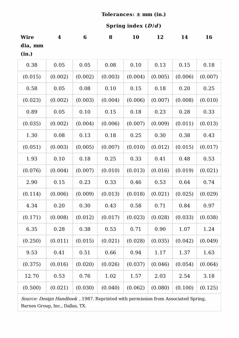
Tolerances: ± mm (in.)
Spring index (D /d )
Wiredia, mm(in.)
4 6 8 10 12 14 16
Source: Design Handbook , 1987. Reprinted with permission from Associated Spring,Barnes Group, Inc., Dallas, TX.
0.38 0.05 0.05 0.08 0.10 0.13 0.15 0.18
(0.015) (0.002) (0.002) (0.003) (0.004) (0.005) (0.006) (0.007)
0.58 0.05 0.08 0.10 0.15 0.18 0.20 0.25
(0.023) (0.002) (0.003) (0.004) (0.006) (0.007) (0.008) (0.010)
0.89 0.05 0.10 0.15 0.18 0.23 0.28 0.33
(0.035) (0.002) (0.004) (0.006) (0.007) (0.009) (0.011) (0.013)
1.30 0.08 0.13 0.18 0.25 0.30 0.38 0.43
(0.051) (0.003) (0.005) (0.007) (0.010) (0.012) (0.015) (0.017)
1.93 0.10 0.18 0.25 0.33 0.41 0.48 0.53
(0.076) (0.004) (0.007) (0.010) (0.013) (0.016) (0.019) (0.021)
2.90 0.15 0.23 0.33 0.46 0.53 0.64 0.74
(0.114) (0.006) (0.009) (0.013) (0.018) (0.021) (0.025) (0.029)
4.34 0.20 0.30 0.43 0.58 0.71 0.84 0.97
(0.171) (0.008) (0.012) (0.017) (0.023) (0.028) (0.033) (0.038)
6.35 0.28 0.38 0.53 0.71 0.90 1.07 1.24
(0.250) (0.011) (0.015) (0.021) (0.028) (0.035) (0.042) (0.049)
9.53 0.41 0.51 0.66 0.94 1.17 1.37 1.63
(0.375) (0.016) (0.020) (0.026) (0.037) (0.046) (0.054) (0.064)
12.70 0.53 0.76 1.02 1.57 2.03 2.54 3.18
(0.500) (0.021) (0.030) (0.040) (0.062) (0.080) (0.100) (0.125)
The squareness tolerances, as noted, is 3°. Spring life is presented in lieu offatigue values.
12.4. CALCULATION OF COMPRESSION SPRINGS
All spring design begins with the application of Hooke’s law. This law statesthat any force acting upon the material is directly proportional to thematerial’s deflection, provided such deflection is within the range of thatmaterial’s elastic limit.
12.4.1. Stress Calculation
Compression springs made of round wire subject this wire to a stressclassified as a torsional stress. The basic formula to calculate such a stress Sis, according to Bernoulli-Euler,
(12-4)
where c = distance from neutral axis at center of section to outside ofmaterial, or one-half of material thickness for a round wire J = polar moment of inertia
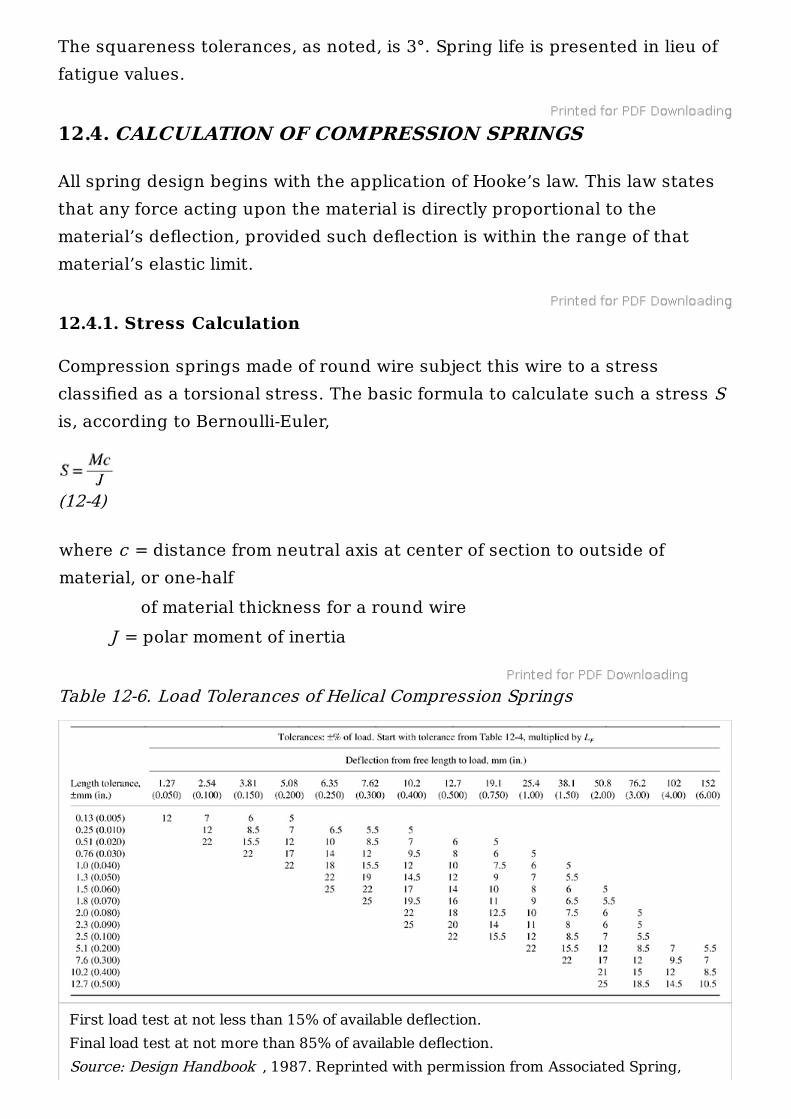
Table 12-6. Load Tolerances of Helical Compression Springs
First load test at not less than 15% of available deflection.Final load test at not more than 85% of available deflection.Source: Design Handbook , 1987. Reprinted with permission from Associated Spring,

Polar moment of inertia for a round section is
where d = wire diameter M = torsional moment, calculated as follows:
where P = load on spring, lb D = mean diameter
Adding a stress-correcting factor K changes this formula to
(12-5)
The sudden emergence of the stress-correcting factor K is due to thenonuniform distribution of torsional stress across the cross section of thewire. This is caused by the curvature of the coil and a direct shear load.Maximum torsional stress can be found at the inner surface of the spring,and its value is assessed with the aid of stress-correcting factor K or K (see Table 12-7), attributable to Dr. A. M. Wahl of Westinghouse Electric Co.
The formula to calculate this correction factor is as follows:
(12-6)
In some conditions, where resultant stresses are distributed more uniformlyaround the cross section, the stress-correcting factor K can be used as
(12-7)
Where elevated temperatures are encountered in the spring-operatingenvironment, the stress distribution is more uniform around the cross sectionand can therefore be estimated, referring to Fig. 12-11.
Barnes Group, Inc., Dallas, TX.
W
W
W 1 W
2
W 2
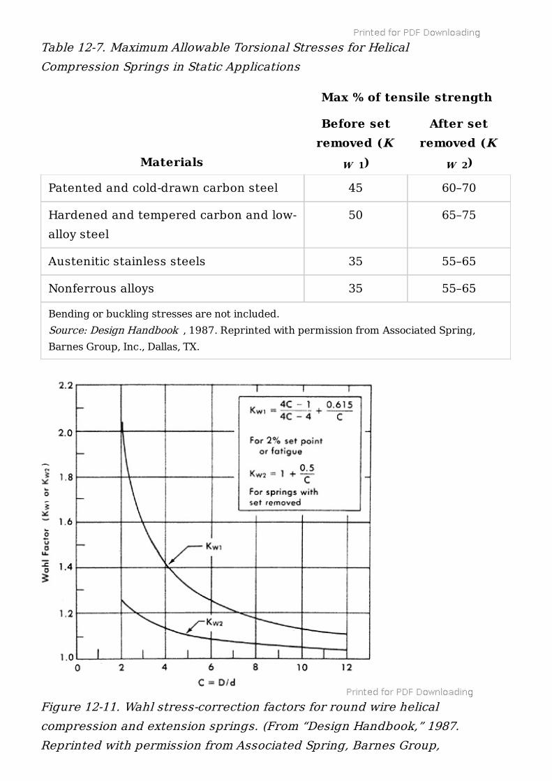
Table 12-7. Maximum Allowable Torsional Stresses for HelicalCompression Springs in Static Applications
Max % of tensile strength
Materials
Before setremoved (K
)
After setremoved (K
)
Bending or buckling stresses are not included.Source: Design Handbook , 1987. Reprinted with permission from Associated Spring,Barnes Group, Inc., Dallas, TX.
Patented and cold-drawn carbon steel 45 60–70
Hardened and tempered carbon and low-alloy steel
50 65–75
Austenitic stainless steels 35 55–65
Nonferrous alloys 35 55–65
W 1 W 2
Figure 12-11. Wahl stress-correction factors for round wire helicalcompression and extension springs. (From “Design Handbook,” 1987.Reprinted with permission from Associated Spring, Barnes Group,
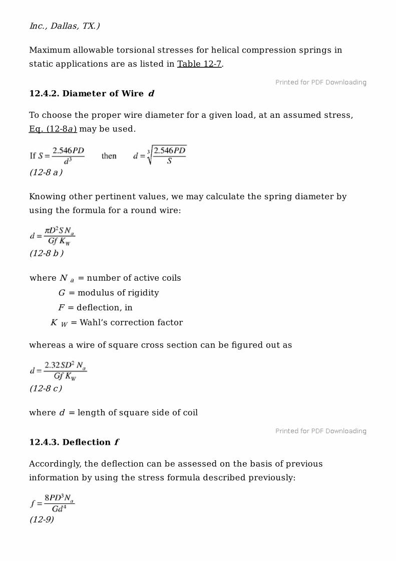
Maximum allowable torsional stresses for helical compression springs instatic applications are as listed in Table 12-7.
12.4.2. Diameter of Wire d
To choose the proper wire diameter for a given load, at an assumed stress,Eq. (12-8a ) may be used.
(12-8 a )
Knowing other pertinent values, we may calculate the spring diameter byusing the formula for a round wire:
(12-8 b )
where N = number of active coils G = modulus of rigidity F = deflection, in K = Wahl’s correction factor
whereas a wire of square cross section can be figured out as
(12-8 c)
where d = length of square side of coil
12.4.3. Deflection f
Accordingly, the deflection can be assessed on the basis of previousinformation by using the stress formula described previously:
(12-9)
Inc., Dallas, TX.)
a
W
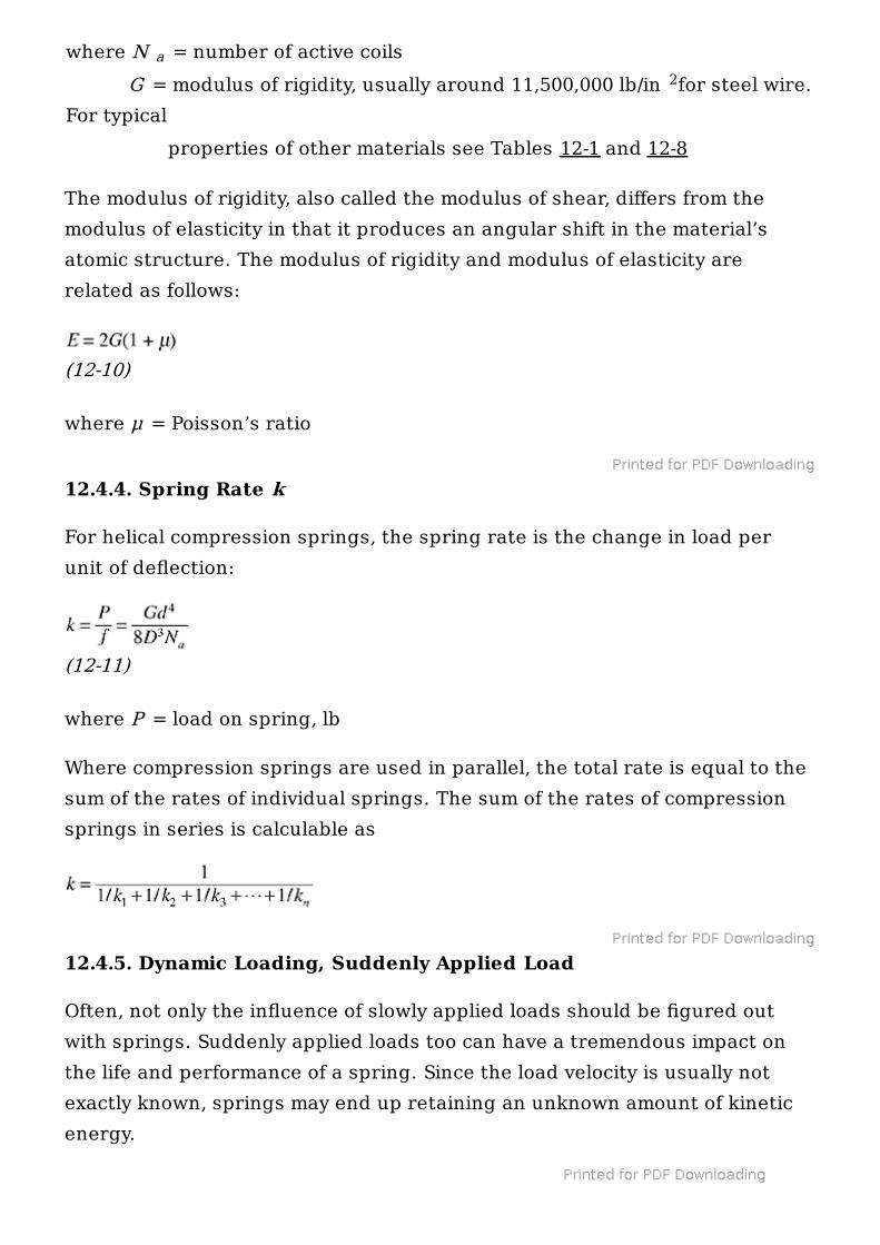
where N = number of active coils G = modulus of rigidity, usually around 11,500,000 lb/in for steel wire.For typical properties of other materials see Tables 12-1 and 12-8
The modulus of rigidity, also called the modulus of shear, differs from themodulus of elasticity in that it produces an angular shift in the material’satomic structure. The modulus of rigidity and modulus of elasticity arerelated as follows:
(12-10)
where μ = Poisson’s ratio
12.4.4. Spring Rate k
For helical compression springs, the spring rate is the change in load perunit of deflection:
(12-11)
where P = load on spring, lb
Where compression springs are used in parallel, the total rate is equal to thesum of the rates of individual springs. The sum of the rates of compressionsprings in series is calculable as
12.4.5. Dynamic Loading, Suddenly Applied Load
Often, not only the influence of slowly applied loads should be figured outwith springs. Suddenly applied loads too can have a tremendous impact onthe life and performance of a spring. Since the load velocity is usually notexactly known, springs may end up retaining an unknown amount of kineticenergy.
a2
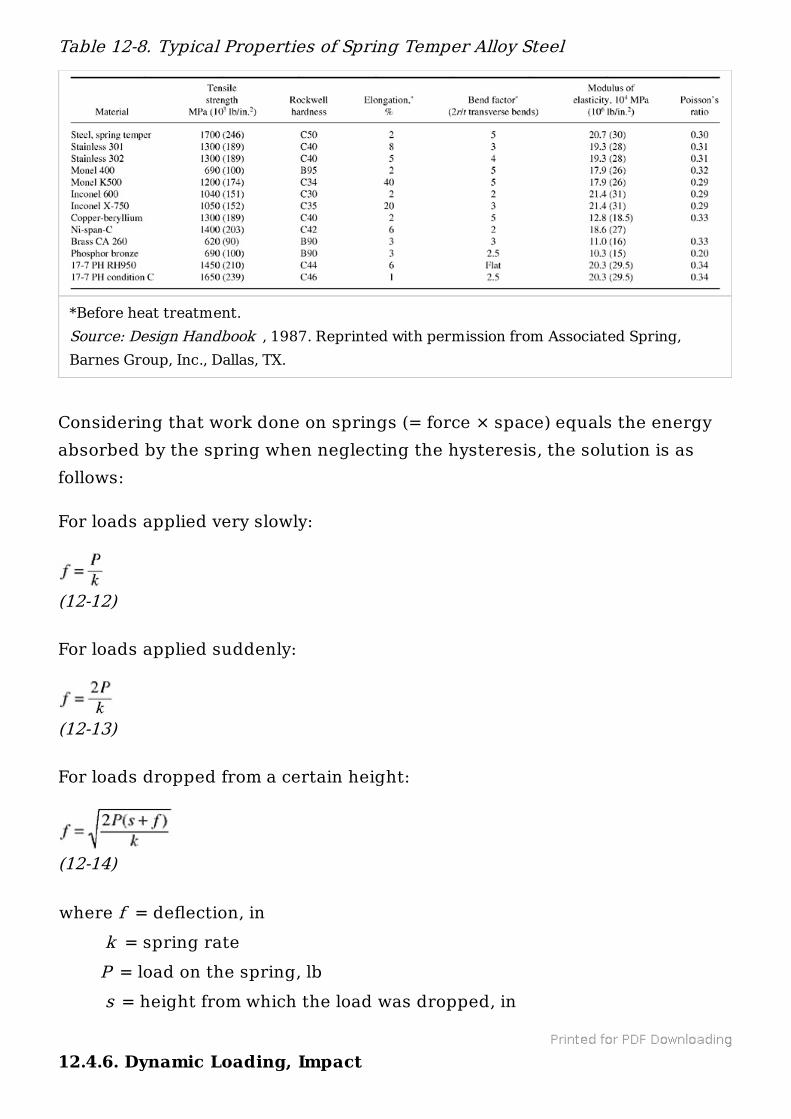
Table 12-8. Typical Properties of Spring Temper Alloy Steel
Considering that work done on springs (= force × space) equals the energyabsorbed by the spring when neglecting the hysteresis, the solution is asfollows:
For loads applied very slowly:
(12-12)
For loads applied suddenly:
(12-13)
For loads dropped from a certain height:
(12-14)
where f = deflection, in k = spring rate P = load on the spring, lb s = height from which the load was dropped, in
12.4.6. Dynamic Loading, Impact
*Before heat treatment.Source: Design Handbook , 1987. Reprinted with permission from Associated Spring,Barnes Group, Inc., Dallas, TX.
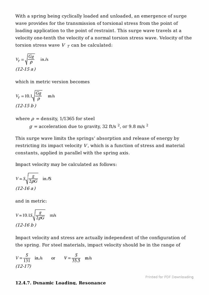
With a spring being cyclically loaded and unloaded, an emergence of surgewave provides for the transmission of torsional stress from the point ofloading application to the point of restraint. This surge wave travels at avelocity one-tenth the velocity of a normal torsion stress wave. Velocity of thetorsion stress wave V can be calculated:
(12-15 a )
which in metric version becomes
(12-15 b )
where ρ = density, 1/1365 for steel g = acceleration due to gravity, 32 ft/s , or 9.8 m/s
This surge wave limits the springs’ absorption and release of energy byrestricting its impact velocity V , which is a function of stress and materialconstants, applied in parallel with the spring axis.
Impact velocity may be calculated as follows:
(12-16 a )
and in metric:
(12-16 b )
Impact velocity and stress are actually independent of the configuration ofthe spring. For steel materials, impact velocity should be in the range of
(12-17)
12.4.7. Dynamic Loading, Resonance
T
2 2
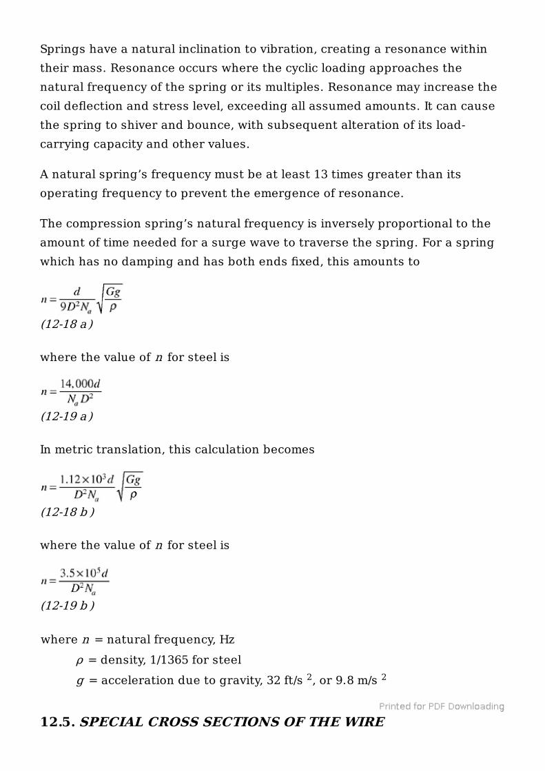
Springs have a natural inclination to vibration, creating a resonance withintheir mass. Resonance occurs where the cyclic loading approaches thenatural frequency of the spring or its multiples. Resonance may increase thecoil deflection and stress level, exceeding all assumed amounts. It can causethe spring to shiver and bounce, with subsequent alteration of its load-carrying capacity and other values.
A natural spring’s frequency must be at least 13 times greater than itsoperating frequency to prevent the emergence of resonance.
The compression spring’s natural frequency is inversely proportional to theamount of time needed for a surge wave to traverse the spring. For a springwhich has no damping and has both ends fixed, this amounts to
(12-18 a )
where the value of n for steel is
(12-19 a )
In metric translation, this calculation becomes
(12-18 b )
where the value of n for steel is
(12-19 b )
where n = natural frequency, Hz ρ = density, 1/1365 for steel g = acceleration due to gravity, 32 ft/s , or 9.8 m/s
12.5. SPECIAL CROSS SECTIONS OF THE WIRE
2 2
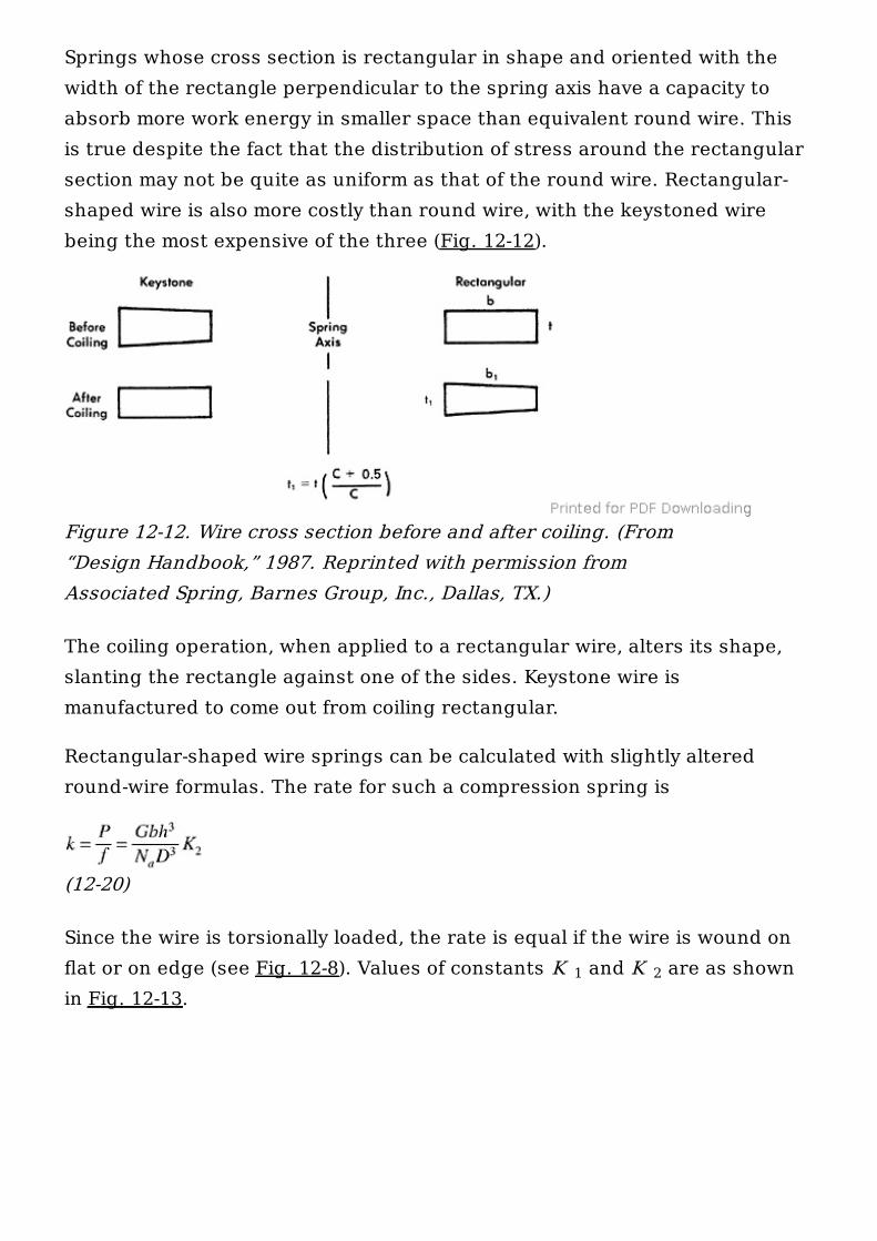
Springs whose cross section is rectangular in shape and oriented with thewidth of the rectangle perpendicular to the spring axis have a capacity toabsorb more work energy in smaller space than equivalent round wire. Thisis true despite the fact that the distribution of stress around the rectangularsection may not be quite as uniform as that of the round wire. Rectangular-shaped wire is also more costly than round wire, with the keystoned wirebeing the most expensive of the three (Fig. 12-12).
The coiling operation, when applied to a rectangular wire, alters its shape,slanting the rectangle against one of the sides. Keystone wire ismanufactured to come out from coiling rectangular.
Rectangular-shaped wire springs can be calculated with slightly alteredround-wire formulas. The rate for such a compression spring is
(12-20)
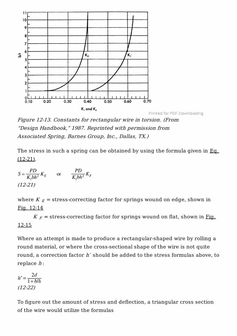
Since the wire is torsionally loaded, the rate is equal if the wire is wound onflat or on edge (see Fig. 12-8). Values of constants K and K are as shownin Fig. 12-13.
Figure 12-12. Wire cross section before and after coiling. (From“Design Handbook,” 1987. Reprinted with permission fromAssociated Spring, Barnes Group, Inc., Dallas, TX.)
1 2
The stress in such a spring can be obtained by using the formula given in Eq.(12-21).
(12-21)
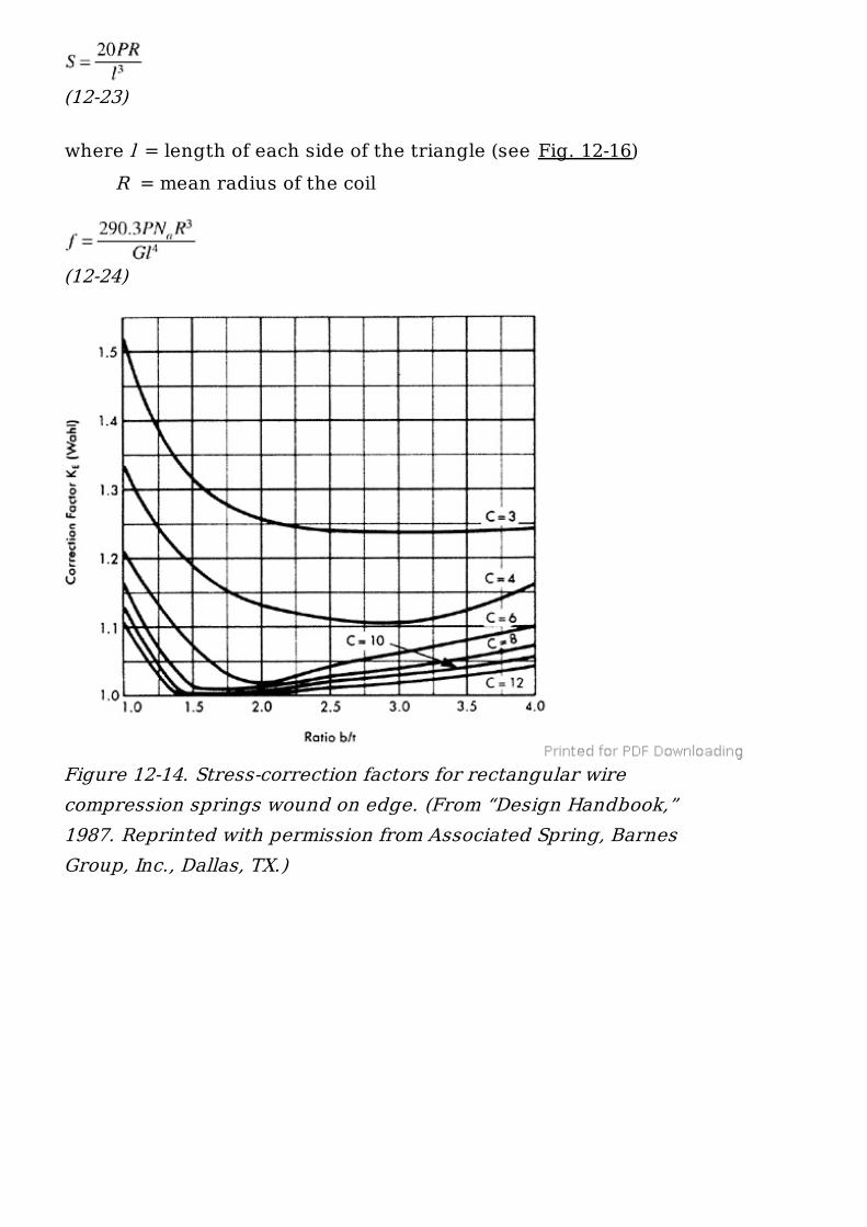
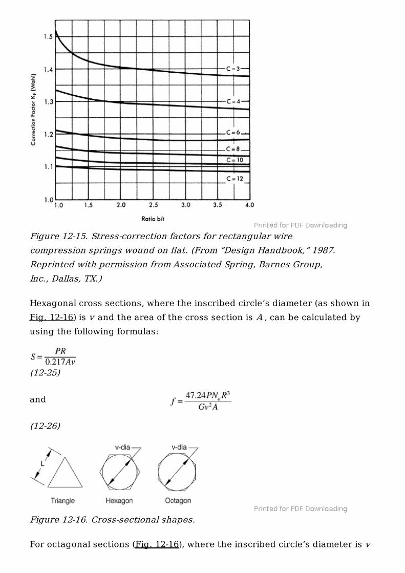
where K = stress-correcting factor for springs wound on edge, shown inFig. 12-14 K = stress-correcting factor for springs wound on flat, shown in Fig.12-15
Where an attempt is made to produce a rectangular-shaped wire by rolling around material, or where the cross-sectional shape of the wire is not quiteround, a correction factor h ′ should be added to the stress formulas above, toreplace h :
(12-22)
To figure out the amount of stress and deflection, a triangular cross sectionof the wire would utilize the formulas
Figure 12-13. Constants for rectangular wire in torsion. (From“Design Handbook,” 1987. Reprinted with permission fromAssociated Spring, Barnes Group, Inc., Dallas, TX.)
E
F
(12-23)
where l = length of each side of the triangle (see Fig. 12-16) R = mean radius of the coil
(12-24)
Figure 12-14. Stress-correction factors for rectangular wirecompression springs wound on edge. (From “Design Handbook,”1987. Reprinted with permission from Associated Spring, BarnesGroup, Inc., Dallas, TX.)
Hexagonal cross sections, where the inscribed circle’s diameter (as shown inFig. 12-16) is v and the area of the cross section is A , can be calculated byusing the following formulas:
(12-25)
and
(12-26)
For octagonal sections (Fig. 12-16), where the inscribed circle’s diameter is v
Figure 12-15. Stress-correction factors for rectangular wirecompression springs wound on flat. (From “Design Handbook,” 1987.Reprinted with permission from Associated Spring, Barnes Group,Inc., Dallas, TX.)
Figure 12-16. Cross-sectional shapes.
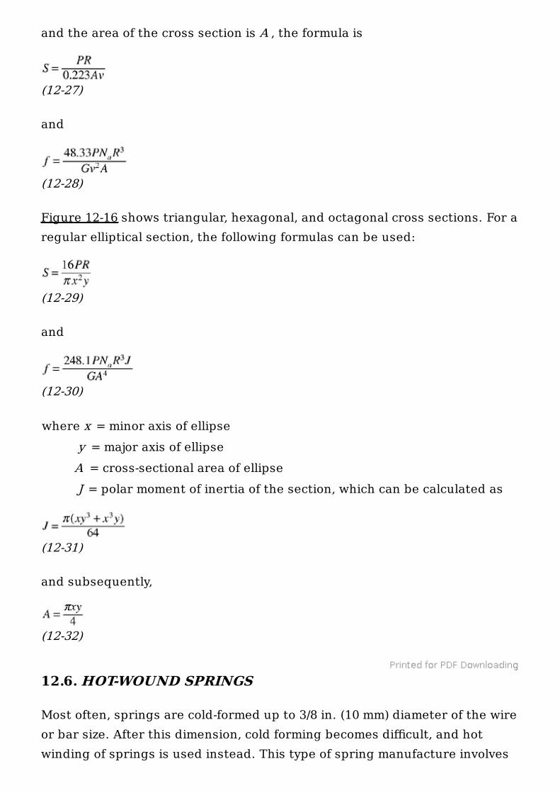
and the area of the cross section is A , the formula is
(12-27)
and
(12-28)
Figure 12-16 shows triangular, hexagonal, and octagonal cross sections. For aregular elliptical section, the following formulas can be used:
(12-29)
and
(12-30)
where x = minor axis of ellipse y = major axis of ellipse A = cross-sectional area of ellipse J = polar moment of inertia of the section, which can be calculated as
(12-31)
and subsequently,
(12-32)
12.6. HOT-WOUND SPRINGS
Most often, springs are cold-formed up to 3/8 in. (10 mm) diameter of the wireor bar size. After this dimension, cold forming becomes difficult, and hotwinding of springs is used instead. This type of spring manufacture involves
heating of the steel up to the austenitic range, winding it, quenching down tomartensitic structure, and tempering to arrive at required properties.
The most often used type of hot-wound spring is the compression spring,utilized as a part of an automobile suspension system or as springs used inrail cars.
Marginally some extension, torsion, and volute springs may be hot-wound aswell.
12.6.1. Design and Calculations
Design parameters and calculations for this type of spring are the same asthose of other springs. The only exception is that of the spring ratecalculation, which here includes an empirical factor K , which is providingfor the adjustment due to scaling-caused complications.
(12-33)
where k = spring rate P = load, lb f = deflection, in G = modulus of rigidity N = number of active coils K = 0.91 for hot-rolled carbon or low-alloy steel materials, which arenot centerless ground = 0.96 for hot-rolled carbon or low-alloy steel materials, centerlessground = 0.95 for carbon or low-alloy steel material on torsion springs
12.6.2. Types of Spring Ends
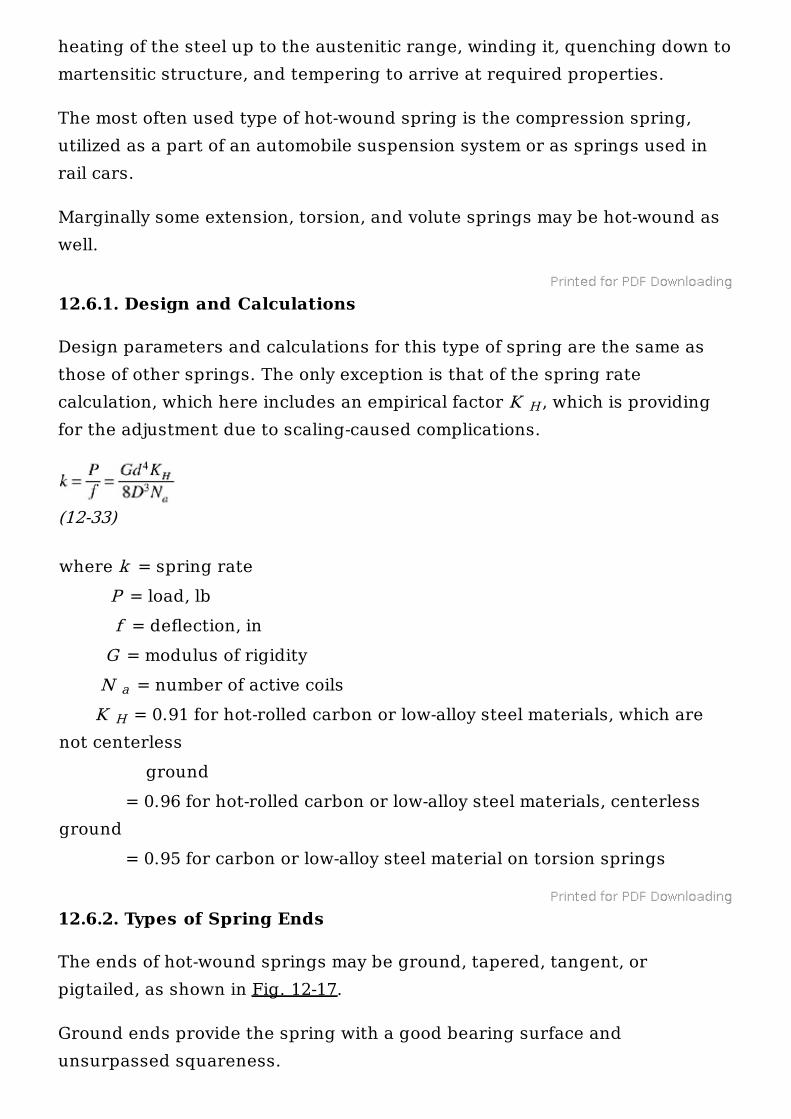
The ends of hot-wound springs may be ground, tapered, tangent, orpigtailed, as shown in Fig. 12-17.
Ground ends provide the spring with a good bearing surface andunsurpassed squareness.
H
a
H
Tapered ends are produced by rolling a taper on the bar. During hot winding,these ends must be guided to provide for their proper orientation. Additionalgrinding improves the spring’s squareness and bearing surface quality.
Tangent ends are standard, with no secondary manufacturing proceduresinvolved. Because of the hot-winding process, springs with tangent endshave a straight portion approximately two wire diameters in size at each end.Their bearing surface must be designed in accordance with the requirementsof such a shape, as it tends to exceed the outline of the spring.
Pigtailed ends are formed along with the hot-winding process. These endsare popular in situations where the spring must be clamped or bolted to itsseat.
12.6.3. Hot-Wound, Noncompression Springs
Extension and torsion springs, utilizing loops and legs, have these additionsto their shapes formed at the same time the spring is wound. For that reason,such shapes should be kept as simple as possible. All elaborate designs thatare difficult to achieve involve reaustenitizing of the spring, with subsequentincrease in manufacturing costs.
Figure 12-17. Typical ends of hot-wound compression springs. (From“Design Handbook,” 1987. Reprinted with permission fromAssociated Spring, Barnes Group, Inc., Dallas, TX.)
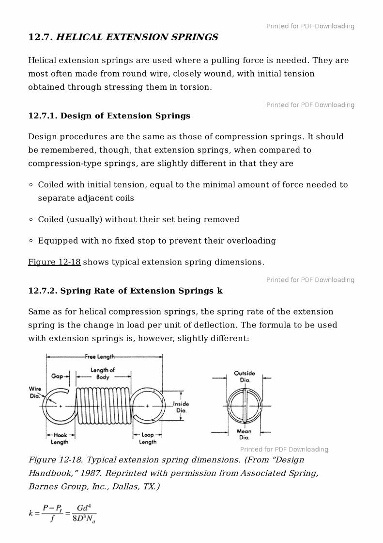
12.7. HELICAL EXTENSION SPRINGS
Helical extension springs are used where a pulling force is needed. They aremost often made from round wire, closely wound, with initial tensionobtained through stressing them in torsion.
12.7.1. Design of Extension Springs
Design procedures are the same as those of compression springs. It shouldbe remembered, though, that extension springs, when compared tocompression-type springs, are slightly different in that they are
Coiled with initial tension, equal to the minimal amount of force needed toseparate adjacent coils
Coiled (usually) without their set being removed
Equipped with no fixed stop to prevent their overloading
Figure 12-18 shows typical extension spring dimensions.
12.7.2. Spring Rate of Extension Springs k
Same as for helical compression springs, the spring rate of the extensionspring is the change in load per unit of deflection. The formula to be usedwith extension springs is, however, slightly different:
Figure 12-18. Typical extension spring dimensions. (From “DesignHandbook,” 1987. Reprinted with permission from Associated Spring,Barnes Group, Inc., Dallas, TX.)
(12-34)
where P is the initial tension. The applicable stress is given by the formula
(12-35)
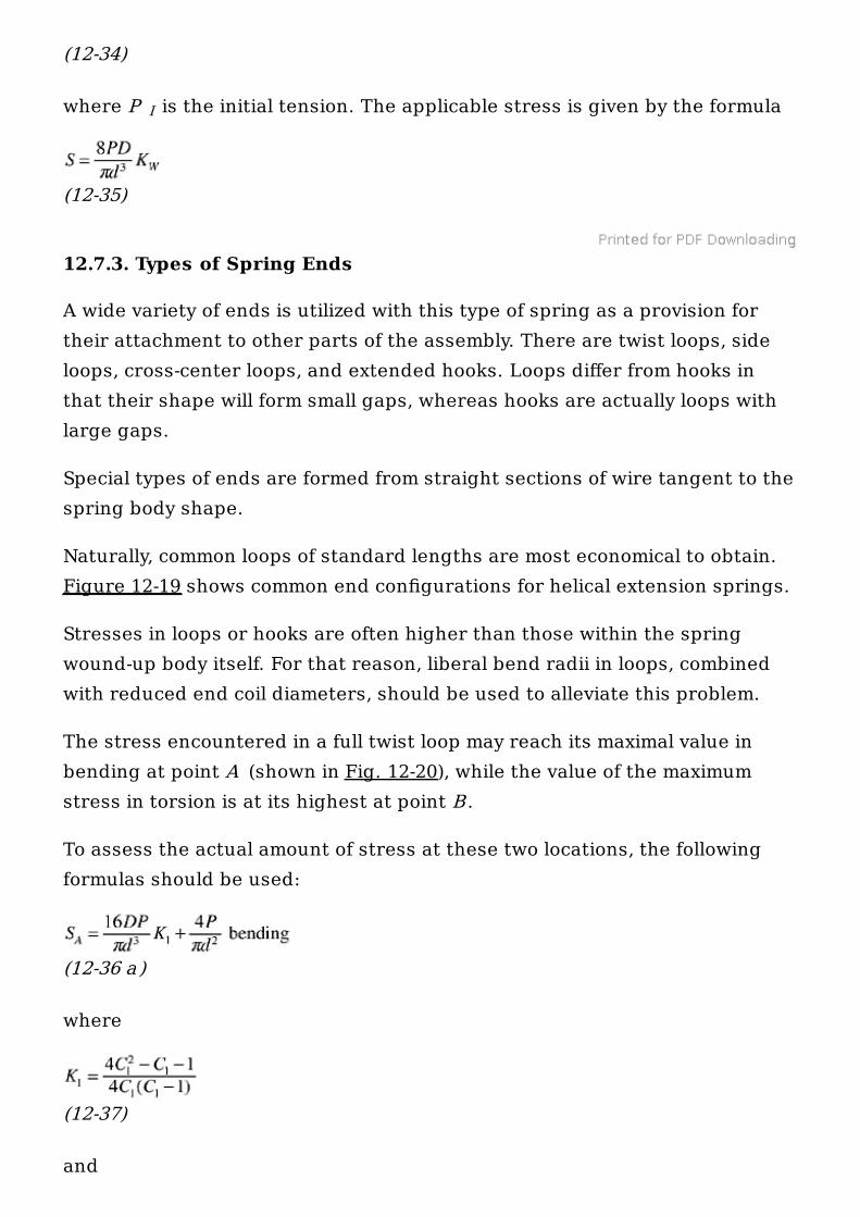
12.7.3. Types of Spring Ends
A wide variety of ends is utilized with this type of spring as a provision fortheir attachment to other parts of the assembly. There are twist loops, sideloops, cross-center loops, and extended hooks. Loops differ from hooks inthat their shape will form small gaps, whereas hooks are actually loops withlarge gaps.
Special types of ends are formed from straight sections of wire tangent to thespring body shape.
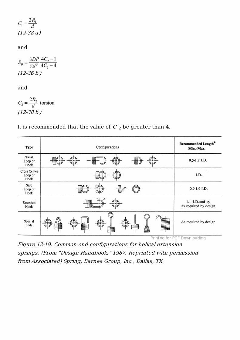
Naturally, common loops of standard lengths are most economical to obtain.Figure 12-19 shows common end configurations for helical extension springs.
Stresses in loops or hooks are often higher than those within the springwound-up body itself. For that reason, liberal bend radii in loops, combinedwith reduced end coil diameters, should be used to alleviate this problem.
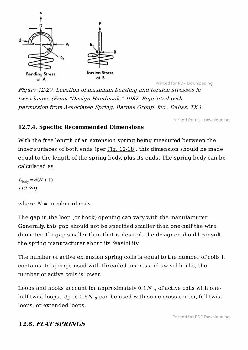
The stress encountered in a full twist loop may reach its maximal value inbending at point A (shown in Fig. 12-20), while the value of the maximumstress in torsion is at its highest at point B .
To assess the actual amount of stress at these two locations, the followingformulas should be used:
(12-36 a )
where
(12-37)
and
I
(12-38 a )
and
(12-36 b )
and
(12-38 b )
It is recommended that the value of C be greater than 4.2
Figure 12-19. Common end configurations for helical extensionsprings. (From “Design Handbook,” 1987. Reprinted with permissionfrom Associated) Spring, Barnes Group, Inc., Dallas, TX.
12.7.4. Specific Recommended Dimensions
With the free length of an extension spring being measured between theinner surfaces of both ends (per Fig. 12-18), this dimension should be madeequal to the length of the spring body, plus its ends. The spring body can becalculated as
(12-39)
where N = number of coils
The gap in the loop (or hook) opening can vary with the manufacturer.Generally, this gap should not be specified smaller than one-half the wirediameter. If a gap smaller than that is desired, the designer should consultthe spring manufacturer about its feasibility.
The number of active extension spring coils is equal to the number of coils itcontains. In springs used with threaded inserts and swivel hooks, thenumber of active coils is lower.
Loops and hooks account for approximately 0.1N of active coils with one-half twist loops. Up to 0.5N can be used with some cross-center, full-twistloops, or extended loops.
12.8. FLAT SPRINGS
Figure 12-20. Location of maximum bending and torsion stresses intwist loops. (From “Design Handbook,” 1987. Reprinted withpermission from Associated Spring, Barnes Group, Inc., Dallas, TX.)
a
a
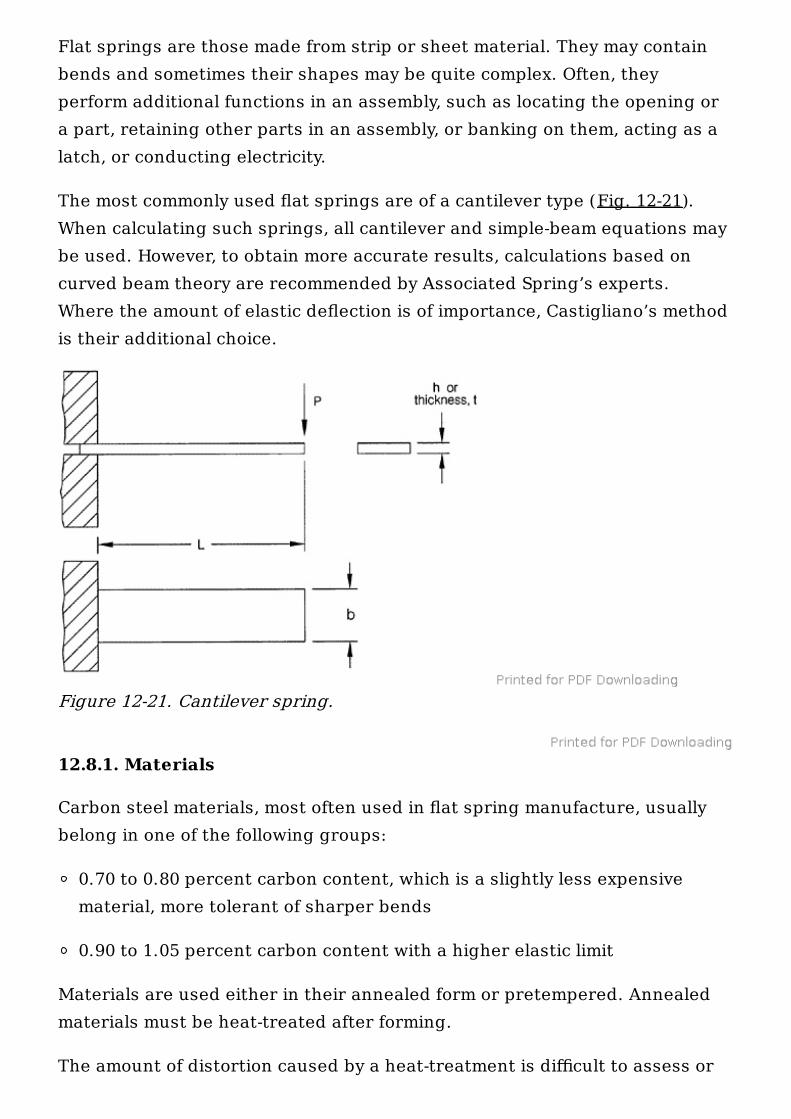
Flat springs are those made from strip or sheet material. They may containbends and sometimes their shapes may be quite complex. Often, theyperform additional functions in an assembly, such as locating the opening ora part, retaining other parts in an assembly, or banking on them, acting as alatch, or conducting electricity.
The most commonly used flat springs are of a cantilever type (Fig. 12-21).When calculating such springs, all cantilever and simple-beam equations maybe used. However, to obtain more accurate results, calculations based oncurved beam theory are recommended by Associated Spring’s experts.Where the amount of elastic deflection is of importance, Castigliano’s methodis their additional choice.
12.8.1. Materials
Carbon steel materials, most often used in flat spring manufacture, usuallybelong in one of the following groups:
0.70 to 0.80 percent carbon content, which is a slightly less expensivematerial, more tolerant of sharper bends
0.90 to 1.05 percent carbon content with a higher elastic limit
Materials are used either in their annealed form or pretempered. Annealedmaterials must be heat-treated after forming.
The amount of distortion caused by a heat-treatment is difficult to assess or
Figure 12-21. Cantilever spring.
calculate. Rather, the designer should depend on a spring manufacturer’sexperience, while avoiding too precise tolerances, sharp corners, and edgeson the spring. Parts with thin and wide cross sections will tend to be moredistorted, sometimes requiring restriking or other adjusting operation.
Pretempered materials must be hard enough to possess a sufficient elasticlimit for their function under desired loads. At the same time, this materialshould not be too hard, as it may fracture during forming or cause breakageand excessive wear to the tooling. The spring-back of pretempered materialis greater, and an allowance for it must be made in the tool designing stage.Again, an experienced spring manufacturer may be the one to evaluate theamount of necessary alterations.
12.8.2. Design and Calculations
Mostly all flat springs are preloaded during the bending operation. Thesurface condition of the material must be smooth, possibly polished, with nodents or nicks. Sharp edges and burrs should be eliminated by design or byabrasive means. Bend radii should be liberal in size, since sharp radii becomestress points, exerting damaging influence on the part. Naturally, all bendsshould be oriented across the material’s grain line.
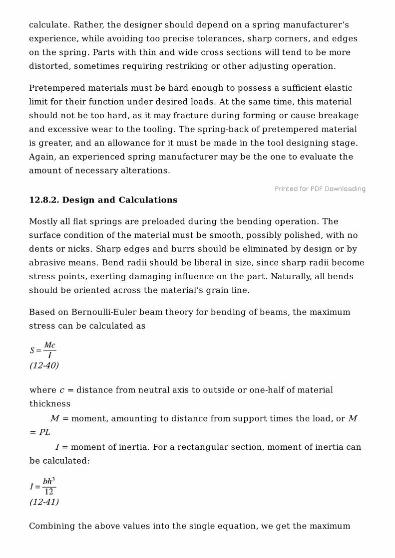
Based on Bernoulli-Euler beam theory for bending of beams, the maximumstress can be calculated as
(12-40)
where c = distance from neutral axis to outside or one-half of materialthickness M = moment, amounting to distance from support times the load, or M= PL I = moment of inertia. For a rectangular section, moment of inertia canbe calculated:
(12-41)
Combining the above values into the single equation, we get the maximum
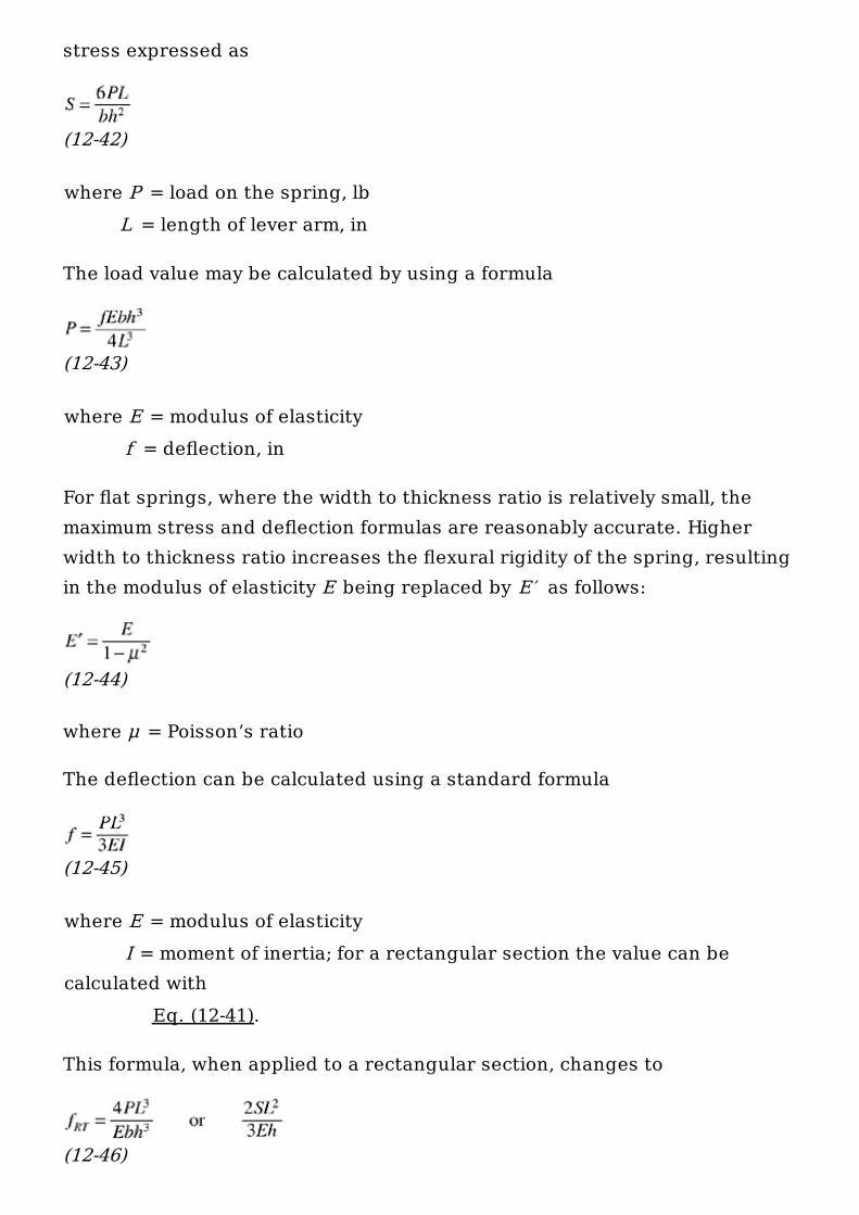
stress expressed as
(12-42)
where P = load on the spring, lb L = length of lever arm, in
The load value may be calculated by using a formula
(12-43)
where E = modulus of elasticity f = deflection, in
For flat springs, where the width to thickness ratio is relatively small, themaximum stress and deflection formulas are reasonably accurate. Higherwidth to thickness ratio increases the flexural rigidity of the spring, resultingin the modulus of elasticity E being replaced by E′ as follows:
(12-44)
where μ = Poisson’s ratio
The deflection can be calculated using a standard formula
(12-45)
where E = modulus of elasticity I = moment of inertia; for a rectangular section the value can becalculated with Eq. (12-41).
This formula, when applied to a rectangular section, changes to
(12-46)
where S = stress
Since L and h values are raised to the third power, accurate measurementsare vital.
All these equations were proved satisfactory where the ratio of deflection tocantilever length F /L was less than 0.3. For larger deflections, E should bereplaced by E′ , as given by Eq. (12-44).
12.9. GAS AND AIR SPRINGS AND THEIR APPLICATIONS
Most probably, forced by an unending and never-resting competition, theindustry had to come up with a different type of springs, to ease theirinstallation, improve their function, and remove the “gray areas” of preloadfrom the spring usage dictionary. With the wound springs, special springpockets had to be milled into the blocks; the correct spring height was anunending problem; and the force buildup, also called preload, was alwayssomewhat a mystery. During the operation, the force of wound springsstarted from zero and progressed upwards, sometimes becomingunpredictable and often even excessive.
Gas springs are different. They are capable of delivering much more force inlesser area than ordinary wound springs. They generate pressure oncontact, eliminating the need for preload. This way the pressure pad can besmaller, the amount of cylinders diminished, the stroke shorter, while theforce produced by springs is constant and unwavering alongside the strokeof a press. Their travel to length ratio is much larger and their pressure canbe easily monitored.
Gas springs are also more balanced. Whereas in an assembly of severalwound springs some may be cracked and the rest may not produce thepressure needed, gas springs are always there, always working. Should theirpressure drop somehow, the gas springs can reclaim the gas needed andprop up the pressure to the demanded levels.
Out of all gasses, nitrogen springs gained the ground across the board. Oneof the reasons may be the low cost of nitrogen gas, but nitrogen is alsononflammable, inert, and tonnage resistant. This means that as the pressureagainst such spring rises, the force of its output increases in proportion to
the volume of gas that was compressed.
Nitrogen springs should never be preloaded, and, actually, manufacturerscaution against preload with determination. But at the same token, nitrogencharge should not be lowered in anticipation of extending the life expectancyof the seal. Such a precaution may actually harm the spring, as the modernseals are designed to operate at the full nitrogen charge.
Their loading is of concern though, as they are not to be used at theoperating pressure exceeding 90 percent of their recommended maximum.
12.9.1. Nitrogen Springs and Their Types
There are several types of nitrogen spring systems available on the markettoday, the difference between each group being provided by the method ofattachment and gas distribution. These types are as described below:
12.9.1.1. MANIFOLD SYSTEM.
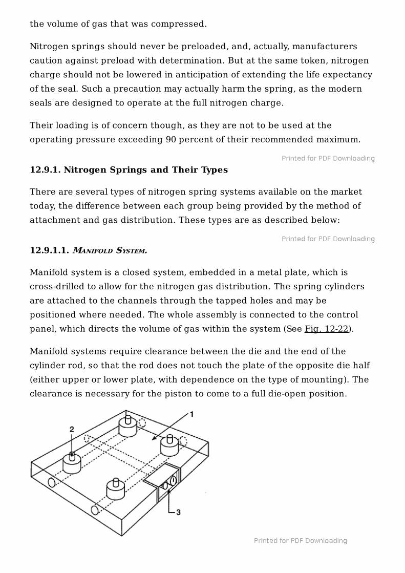
Manifold system is a closed system, embedded in a metal plate, which iscross-drilled to allow for the nitrogen gas distribution. The spring cylindersare attached to the channels through the tapped holes and may bepositioned where needed. The whole assembly is connected to the controlpanel, which directs the volume of gas within the system (See Fig. 12-22).
Manifold systems require clearance between the die and the end of thecylinder rod, so that the rod does not touch the plate of the opposite die half(either upper or lower plate, with dependence on the type of mounting). Theclearance is necessary for the piston to come to a full die-open position.
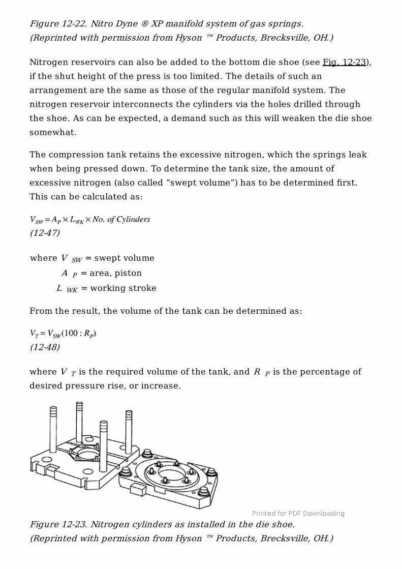
Nitrogen reservoirs can also be added to the bottom die shoe (see Fig. 12-23),if the shut height of the press is too limited. The details of such anarrangement are the same as those of the regular manifold system. Thenitrogen reservoir interconnects the cylinders via the holes drilled throughthe shoe. As can be expected, a demand such as this will weaken the die shoesomewhat.
The compression tank retains the excessive nitrogen, which the springs leakwhen being pressed down. To determine the tank size, the amount ofexcessive nitrogen (also called “swept volume”) has to be determined first.This can be calculated as:
(12-47)
where V = swept volume A = area, piston L = working stroke
From the result, the volume of the tank can be determined as:
(12-48)
where V is the required volume of the tank, and R is the percentage ofdesired pressure rise, or increase.
Figure 12-22. Nitro Dyne ® XP manifold system of gas springs.(Reprinted with permission from Hyson ™ Products, Brecksville, OH.)
SW
P
WK
T P
Figure 12-23. Nitrogen cylinders as installed in the die shoe.(Reprinted with permission from Hyson ™ Products, Brecksville, OH.)
Pressure increase, also called pressure rise, is generally recommended at 15–20 percent for draw dies and 30–40 percent for strippers, form pads, andcam returns.
12.9.1.2. 12-9-1-2 HOSE AND TANK SYSTEM.
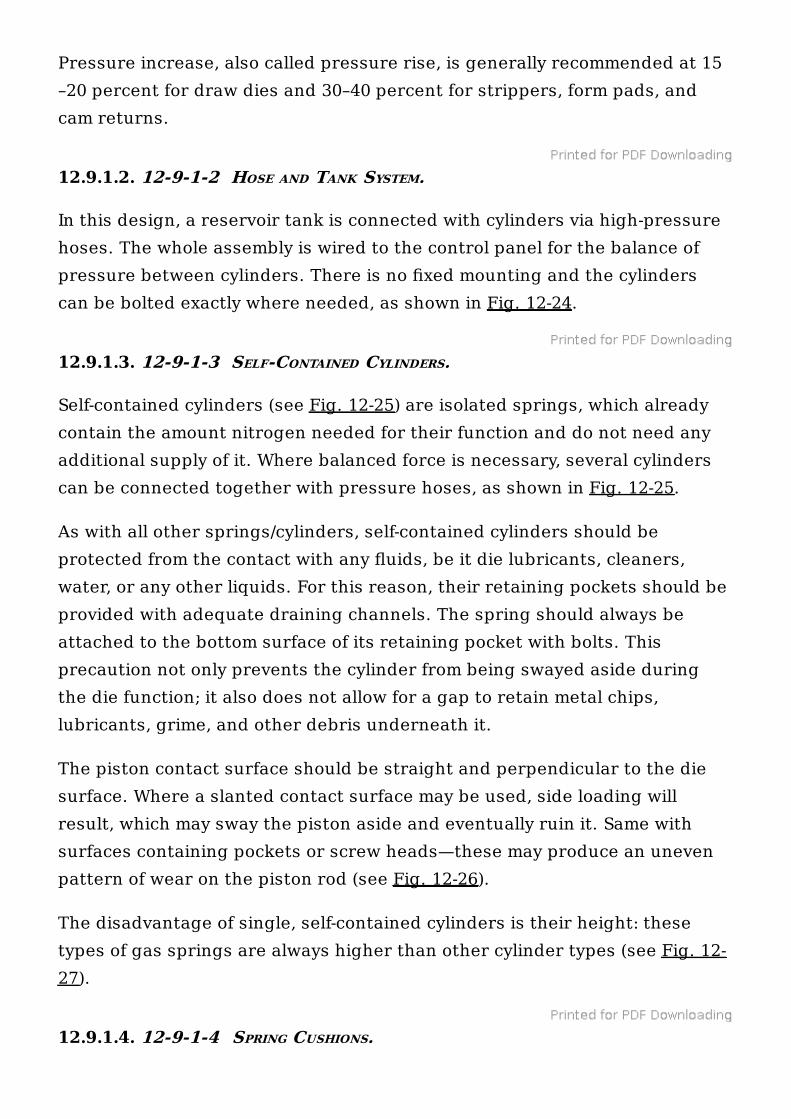
In this design, a reservoir tank is connected with cylinders via high-pressurehoses. The whole assembly is wired to the control panel for the balance ofpressure between cylinders. There is no fixed mounting and the cylinderscan be bolted exactly where needed, as shown in Fig. 12-24.
12.9.1.3. 12-9-1-3 SELF-CONTAINED CYLINDERS.
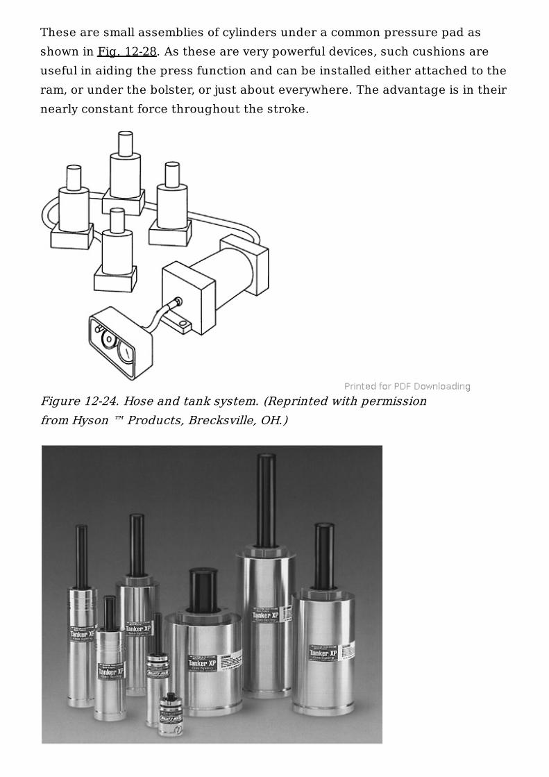
Self-contained cylinders (see Fig. 12-25) are isolated springs, which alreadycontain the amount nitrogen needed for their function and do not need anyadditional supply of it. Where balanced force is necessary, several cylinderscan be connected together with pressure hoses, as shown in Fig. 12-25.
As with all other springs/cylinders, self-contained cylinders should beprotected from the contact with any fluids, be it die lubricants, cleaners,water, or any other liquids. For this reason, their retaining pockets should beprovided with adequate draining channels. The spring should always beattached to the bottom surface of its retaining pocket with bolts. Thisprecaution not only prevents the cylinder from being swayed aside duringthe die function; it also does not allow for a gap to retain metal chips,lubricants, grime, and other debris underneath it.
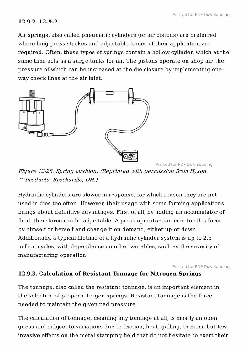
The piston contact surface should be straight and perpendicular to the diesurface. Where a slanted contact surface may be used, side loading willresult, which may sway the piston aside and eventually ruin it. Same withsurfaces containing pockets or screw heads—these may produce an unevenpattern of wear on the piston rod (see Fig. 12-26).
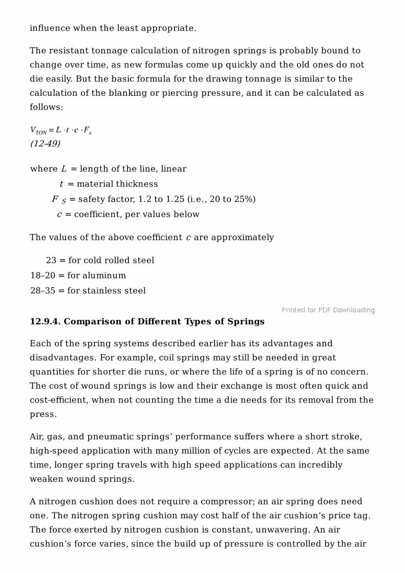
The disadvantage of single, self-contained cylinders is their height: thesetypes of gas springs are always higher than other cylinder types (see Fig. 12-27).
12.9.1.4. 12-9-1-4 SPRING CUSHIONS.
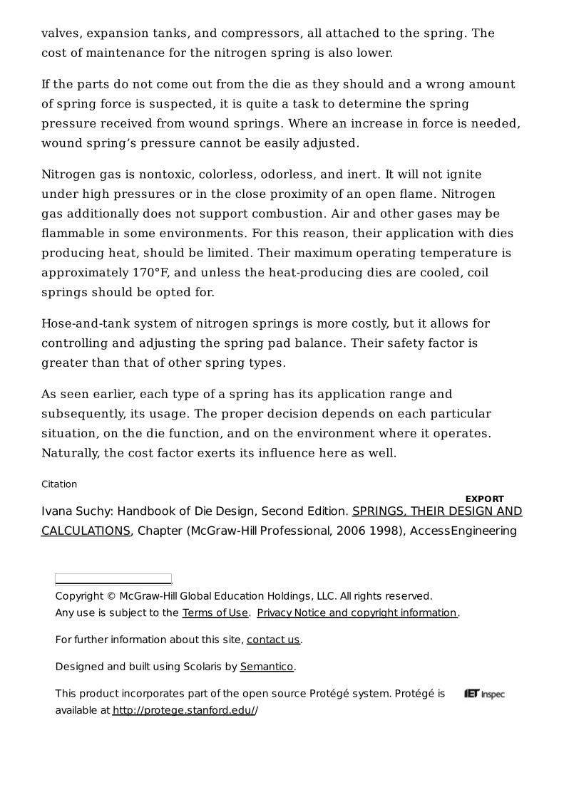
These are small assemblies of cylinders under a common pressure pad asshown in Fig. 12-28. As these are very powerful devices, such cushions areuseful in aiding the press function and can be installed either attached to theram, or under the bolster, or just about everywhere. The advantage is in theirnearly constant force throughout the stroke.
Figure 12-24. Hose and tank system. (Reprinted with permissionfrom Hyson ™ Products, Brecksville, OH.)
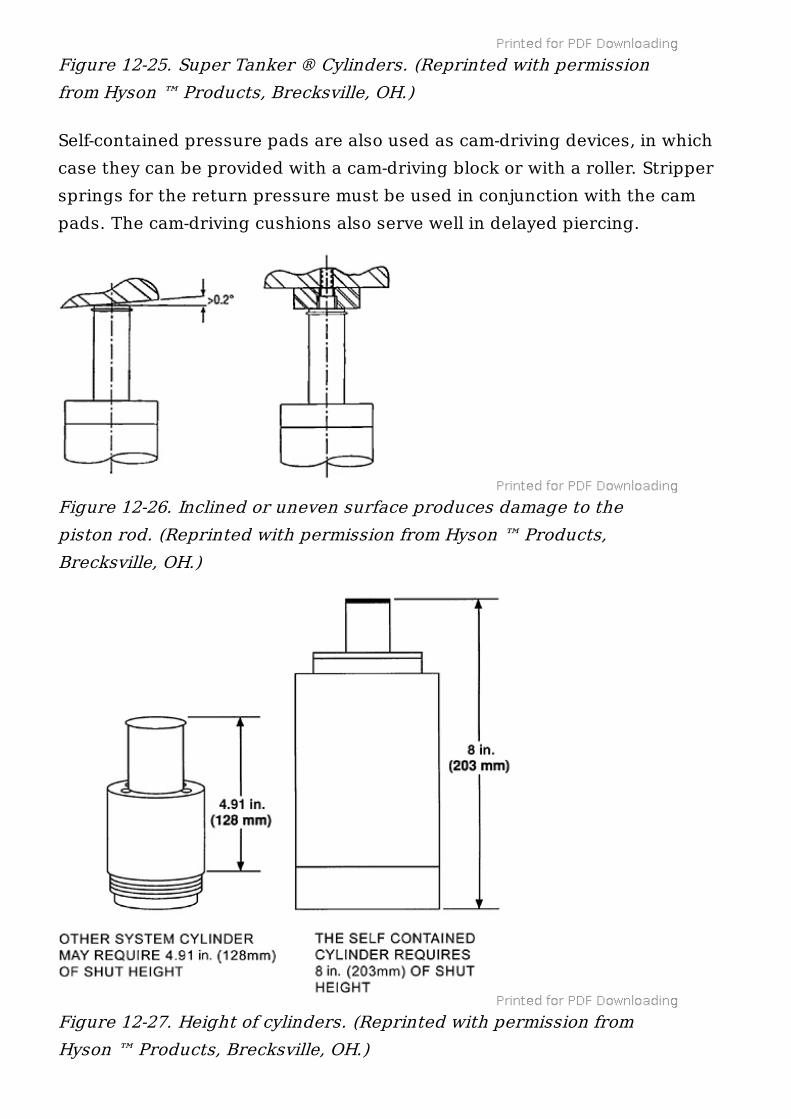
Self-contained pressure pads are also used as cam-driving devices, in whichcase they can be provided with a cam-driving block or with a roller. Strippersprings for the return pressure must be used in conjunction with the campads. The cam-driving cushions also serve well in delayed piercing.
Figure 12-25. Super Tanker ® Cylinders. (Reprinted with permissionfrom Hyson ™ Products, Brecksville, OH.)
Figure 12-26. Inclined or uneven surface produces damage to thepiston rod. (Reprinted with permission from Hyson ™ Products,Brecksville, OH.)
Figure 12-27. Height of cylinders. (Reprinted with permission fromHyson ™ Products, Brecksville, OH.)
12.9.2. 12-9-2
Air springs, also called pneumatic cylinders (or air pistons) are preferredwhere long press strokes and adjustable forces of their application arerequired. Often, these types of springs contain a hollow cylinder, which at thesame time acts as a surge tanks for air. The pistons operate on shop air, thepressure of which can be increased at the die closure by implementing one-way check lines at the air inlet.
Hydraulic cylinders are slower in response, for which reason they are notused in dies too often. However, their usage with some forming applicationsbrings about definitive advantages. First of all, by adding an accumulator offluid, their force can be adjustable. A press operator can monitor this forceby himself or herself and change it on demand, either up or down.Additionally, a typical lifetime of a hydraulic cylinder system is up to 2.5million cycles, with dependence on other variables, such as the severity ofmanufacturing operation.
12.9.3. Calculation of Resistant Tonnage for Nitrogen Springs
The tonnage, also called the resistant tonnage, is an important element inthe selection of proper nitrogen springs. Resistant tonnage is the forceneeded to maintain the given pad pressure.
The calculation of tonnage, meaning any tonnage at all, is mostly an openguess and subject to variations due to friction, heat, galling, to name but fewinvasive effects on the metal stamping field that do not hesitate to exert their
Figure 12-28. Spring cushion. (Reprinted with permission from Hyson™ Products, Brecksville, OH.)
influence when the least appropriate.
The resistant tonnage calculation of nitrogen springs is probably bound tochange over time, as new formulas come up quickly and the old ones do notdie easily. But the basic formula for the drawing tonnage is similar to thecalculation of the blanking or piercing pressure, and it can be calculated asfollows:
(12-49)
where L = length of the line, linear t = material thickness F = safety factor, 1.2 to 1.25 (i.e., 20 to 25%) c = coefficient, per values below
The values of the above coefficient c are approximately
23 = for cold rolled steel18–20 = for aluminum28–35 = for stainless steel
12.9.4. Comparison of Different Types of Springs
Each of the spring systems described earlier has its advantages anddisadvantages. For example, coil springs may still be needed in greatquantities for shorter die runs, or where the life of a spring is of no concern.The cost of wound springs is low and their exchange is most often quick andcost-efficient, when not counting the time a die needs for its removal from thepress.
Air, gas, and pneumatic springs’ performance suffers where a short stroke,high-speed application with many million of cycles are expected. At the sametime, longer spring travels with high speed applications can incrediblyweaken wound springs.
A nitrogen cushion does not require a compressor; an air spring does needone. The nitrogen spring cushion may cost half of the air cushion’s price tag.The force exerted by nitrogen cushion is constant, unwavering. An aircushion’s force varies, since the build up of pressure is controlled by the air
S
Copyright © McGraw-Hill Global Education Holdings, LLC. All rights reserved. Any use is subject to the Terms of Use. Privacy Notice and copyright information.
For further information about this site, contact us.
Designed and built using Scolaris by Semantico.
This product incorporates part of the open source Protégé system. Protégé isavailable at http://protege.stanford.edu//
valves, expansion tanks, and compressors, all attached to the spring. Thecost of maintenance for the nitrogen spring is also lower.
If the parts do not come out from the die as they should and a wrong amountof spring force is suspected, it is quite a task to determine the springpressure received from wound springs. Where an increase in force is needed,wound spring’s pressure cannot be easily adjusted.
Nitrogen gas is nontoxic, colorless, odorless, and inert. It will not igniteunder high pressures or in the close proximity of an open flame. Nitrogengas additionally does not support combustion. Air and other gases may beflammable in some environments. For this reason, their application with diesproducing heat, should be limited. Their maximum operating temperature isapproximately 170°F, and unless the heat-producing dies are cooled, coilsprings should be opted for.
Hose-and-tank system of nitrogen springs is more costly, but it allows forcontrolling and adjusting the spring pad balance. Their safety factor isgreater than that of other spring types.
As seen earlier, each type of a spring has its application range andsubsequently, its usage. The proper decision depends on each particularsituation, on the die function, and on the environment where it operates.Naturally, the cost factor exerts its influence here as well.
Citation
Ivana Suchy: Handbook of Die Design, Second Edition. SPRINGS, THEIR DESIGN ANDCALCULATIONS, Chapter (McGraw-Hill Professional, 2006 1998), AccessEngineering
EXPORT
![Colorado Springs Fire Department1].pdf · “Automatic Fire Sprinkler Systems ... hydraulic calculations need not be submitted as long ... Colorado Springs Fire Department](https://img.pdfslide.us/doc/110x75/5b3349e37f8b9a2c0b8d37b5/colorado-springs-fire-1pdf-automatic-fire-sprinkler-systems-hydraulic.jpg)