Embed Size (px)
Citation preview
Journal for Technology of Plasticity, Vol. 37 (2012), Number 1
*Corresponding author’s email: [email protected]
SPRINGBACK PREDICTION IN SHEET METAL FORMING PROCESSES
Slota Ján, Jurčišin Miroslav
Department of Technologies and Materials, Faculty of Mechanical Engineering, Technical University of Košice, Slovakia
ABSTRACT The objective of this paper is springback determination of sheet metals in various cases in air bending process. The practical part consists of two parts. First part deals with experiment of air bending process using three different categories of steel, different bending depths and different die geometry. Influence of these technological variables is illustrated and compared with results of numerical simulation of these processes. Implicit and explicit commercial codes were used. This paper used a modern measurement methods performed in MATLAB system. Key words: finite element method, air bending, AutoForm, Pam-Stamp, springback 1. INTRODUCTION The most common problem in area of bending technology is problem of achieving accurate and repeatable bending angle. In processes of sheet metal forming is this problem frequently observed, and is caused by elastic springback [1]. Elastic springback can be briefly defined as a dimensional change generated in the part, which occurs due to elastic recovery after the tool is released. This phenomenon causes the dimensional deviations [2]. Importance of springback prediction is significant also from economical aspect [3]. Nowadays is problematic of springback the current issue in automotive industry, considering use UHSS, AHSS, CP, TWIP etc. which have high strength [21]. The handy tables [4, 5] and graphs [6] were in the past the traditional ways to predict springback. But these methods didn’t describe the whole scale of reached bending angles [2]. Another way to springback determination is analytical determination [24, 25] but these methods are time-consuming and computationally intensive. Technological variables for example blank thickness, tool radius, bending angle etc. influence springback amount [7, 8]. Material properties, as for example Young’s modulus, constitutive behavior in plastic field, yield stress, Bauschinger
94
Journal for Technology of Plasticity, Vol. 37 (2012), Number 1
effect etc have also influence to the springback amount [9,10,11]. Air bending is the process, where different bending angle could be achieved [2]. Due to this circumstance, this method of bending in this work was used. Due to fact that AHSS steels have been intensively used in the automotive industry, this category of steel among the UHSS and mild steel has been used [12, 21]. Modern way of springback prediction is aimed to the numerical simulation of springback. Several codes can be use for numerical simulation of springback, for example Autoform, PAM – STAMP, Dynaform etc. In this work two commercial FEM codes were used. Definition of input parameters of simulation software is very important. The most important is selection of material models. It means the hardening curve and yield function. Early developed material models were for example Tresca and von Misses. These models were developed according to parameters obtained from simple tensile test. These material models were soon insufficient, because they didn’t describe several parameters of material behavior as for example anisotropy, kinetic hardening, etc [13, 14]. The most accurate material description is using experimentally measured mechanical properties and use approximation for defining hardening curve [22, 23]. In air bending, increasingly adaptive control is applied to address the problem of variable material properties [20]. In experimental part of this paper, the same yield criterion and hardening curve in both of software were used. This was done on account of ensuring the same condition in codes, and also on account to the determination, if used material models are convenient for all categories of steel. As was mentioned, in both numerical simulation of experiment, Hill 48 yield criterion was used. This criterion is defined as follows [15, 16]: (1)
where: F, G, H, L, M and N [-] - Hill’s anisotropic parameters, which can be expressed by
Lankford’s coefficients, σxy [MPa] - x, y are the principal anisotropic axes. In the case of sheet metals, axis 1 is usually parallel to the rolling direction, 2 is parallel to the transverse direction [15].
( )
( )( )( )
0 90 450 0
90 0 0 0 90 0
1 21, , ,1 1 1 2 1
r r rr rF G H N
r r r r r r+ +
= = = =+ + + +
(2)
where: r0, r45, r90 [-] - Lankford’s coefficient which represents anisotropy values measured in 0°,
45° and 90° to the rolling direction, L and M are equal to N Hill yield criterion was set in the combination with hardening curve defined by Hollomon which is described by law [17]:
nCσ ε= (3)
where: σ [MPa] - true stress
ε [-] - true plastic strain C [MPa] - strain hardening coefficient n [-] - strain hardening exponent
( ) ( ) ( ) ( )2 2 222 33 33 11 11 22
2 2 2 223 31 122 2 2 0ij F G H
L M N
ϕ σ σ σ σ σ σ σ
σ σ σ σ
= − + − + − +
+ + − =
95
Journal for Technology of Plasticity, Vol. 37 (2012), Number 1
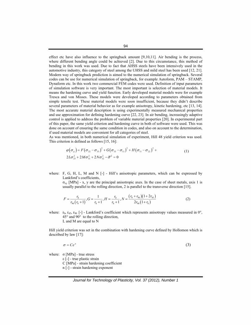
2. OBJECTIVES AND PROCESS OF EXPERIMENT The aim of this experiment was first to determine the influence of technological parameters on the amount of springback, and secondly accuracy of springback prediction using simulation software PA-STAMP 2G and Autoform. During the experiment, ten different bending angle, and two different die width were used. Three different categories of steels were used: HSS, UHSS and mild steel. Since yield stress has a significant influence to the springback amount, the different springback angle after unloading was observed. The stress strain curves of used materials are illustrated on Fig. 1. The thicknesses of materials were as follows: UHSS – 0.75 mm, HSS – 0.8 mm and mild steel 0.85 mm. All specimens were cut in direction transverse to the bending direction.
Fig.1 - Stress – strain diagram of used steels Mechanical properties were measured in three mentioned rolling directions. Exams were performed on machine Tiratest 2300. Test rod of 80 mm according to EN 10002-1 was used. Results of mechanical properties illustrate Table 1. , 2 and 3. Table 1 - Mechanical properties of HSS – H220PD
Rolling Direction
[°]
Rp0,2 (Re) [MPa]
Rm [MPa]
A80 [%]
n [-]
C [MPa]
r [-]
0 219 385 34.50.231 673.27
1.172 45 225 368 37.4 1.782 90 238 383 35.8 1.823
Table 2 - Mechanical properties of UHSS – TRIP RAK 40/70
Rolling Direction
[°]
Rp0,2 (Re) [MPa]
Rm [MPa]
A80 [%]
n [-]
C [MPa]
r [-]
0 442 771 27.7 0.29 1492.28
0.686 45 441 762 25.4 0.87 90 450 766 25.9 0.838
96
Journal for Technology of Plasticity, Vol. 37 (2012), Number 1
Table 3 - Mechanical properties of mild steel DC06 Rolling
Direction [°]
Rp0,2 (Re) [MPa]
Rm [MPa]
A80 [%]
n [-]
C [MPa]
r [-]
0 138 277 53.0 0.261 538.54
1.665 45 142 282 50.4 1.601 90 141 277 51.7 2.112
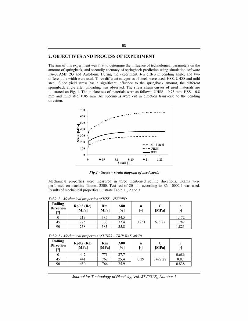
Parameters in Tables 1-3 are necessary to define Hill 48 yield criterion and Hollomon hardening curve. Real experiment was performed onto hydraulic press ZD40. All specimens were bent in equal conditions. 2.1 Process of experiment As was mentioned, experiment was performed on hydraulic press ZD40. Sheet metal strips were cut from three different categories of steel at dimension of 160 x 40 mm. Fig. 2 illustrates the used tool. Diameter of die was 50 mm and diameter of punch was 30 mm. Two different die widths were set. First, 50 mm die width and second 110 mm die width.
Fig.2 - Assembly of tool with indicating variables of process Various bending depth cause various bending angle. After the punch stopped, and assembly was closed, picture was taken. Pictures were taken by camera from the same distance for each bending depth. After tool was released, another picture was taken. It was done due to graphical MATLAB measuring method, which were used on account the difficulty of conventional measuring method. MATLAB measuring method will be explained in stage 2.3. After all bending depths in addition of two die widths were performed, and pictures were taken, next step was numerical simulation of this process.
97
Journal for Technology of Plasticity, Vol. 37 (2012), Number 1
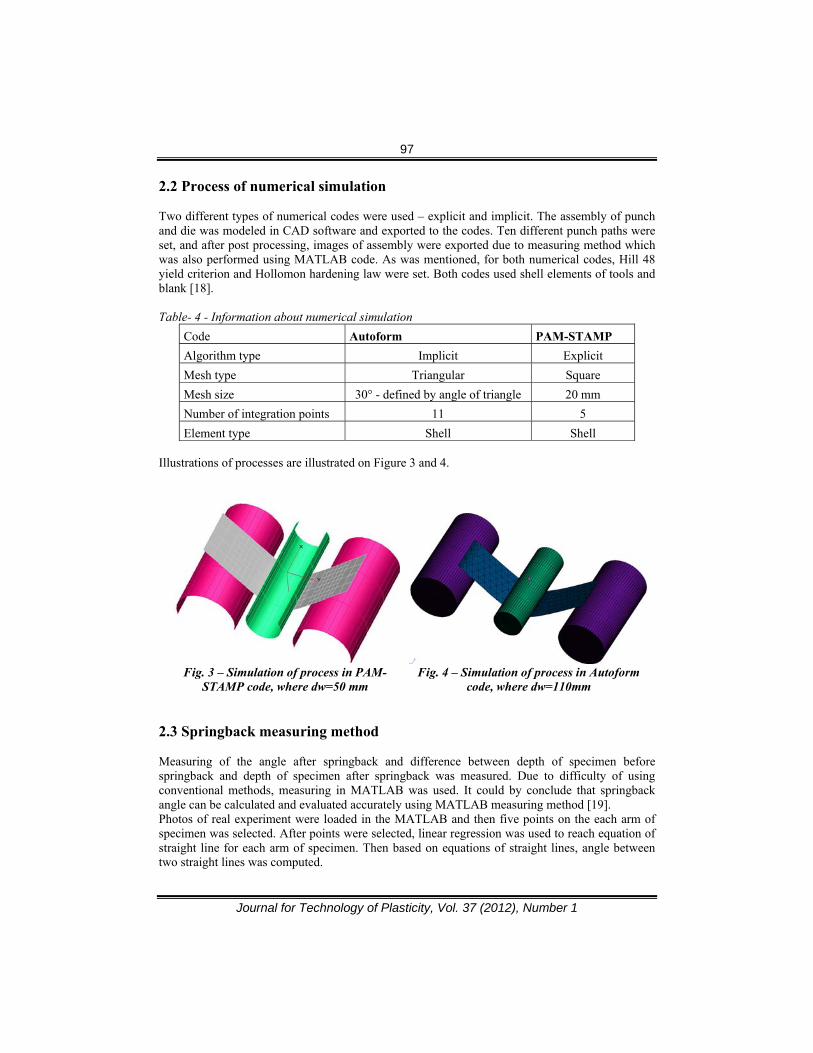
2.2 Process of numerical simulation Two different types of numerical codes were used – explicit and implicit. The assembly of punch and die was modeled in CAD software and exported to the codes. Ten different punch paths were set, and after post processing, images of assembly were exported due to measuring method which was also performed using MATLAB code. As was mentioned, for both numerical codes, Hill 48 yield criterion and Hollomon hardening law were set. Both codes used shell elements of tools and blank [18].
Table- 4 - Information about numerical simulation
Code Autoform PAM-STAMP Algorithm type Implicit Explicit Mesh type Triangular Square Mesh size 30° - defined by angle of triangle 20 mm Number of integration points 11 5 Element type Shell Shell
Illustrations of processes are illustrated on Figure 3 and 4.
Fig. 3 – Simulation of process in PAM-
STAMP code, where dw=50 mm Fig. 4 – Simulation of process in Autoform
code, where dw=110mm
2.3 Springback measuring method
Measuring of the angle after springback and difference between depth of specimen before springback and depth of specimen after springback was measured. Due to difficulty of using conventional methods, measuring in MATLAB was used. It could by conclude that springback angle can be calculated and evaluated accurately using MATLAB measuring method [19]. Photos of real experiment were loaded in the MATLAB and then five points on the each arm of specimen was selected. After points were selected, linear regression was used to reach equation of straight line for each arm of specimen. Then based on equations of straight lines, angle between two straight lines was computed.
98
Journal for Technology of Plasticity, Vol. 37 (2012), Number 1
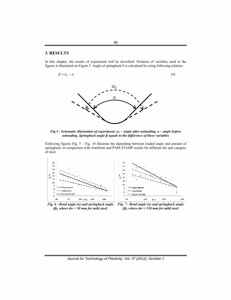
3. RESULTS In this chapter, the results of experiment will be described. Notation of variables used in the figures is illustrated on Figure 5. Angle of springback ß is calculated by using following relation :
Uβ α α= − (4)
Fig.5 - Schematic illustration of experiment: αU – angle after unloading, α – angle before
unloading. Springback angle β equals to the difference of these variables Following figures Fig. 5 – Fig. 10 illustrate the depending between loaded angle and amount of springback, in comparison with Autoform and PAM-STAMP results for different dw and category of steel.
Fig. 6 - Bend angle (α) and springback angle (β), where dw = 50 mm for mild steel.
Fig. 7 - Bend angle (α) and springback angle
(β), where dw = 110 mm for mild steel.
99
Journal for Technology of Plasticity, Vol. 37 (2012), Number 1
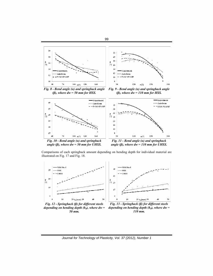
Fig. 8 - Bend angle (α) and springback angle (β), where dw = 50 mm for HSS.
Fig. 9 - Bend angle (α) and springback angle
(β), where dw = 110 mm for HSS.
Fig. 10 - Bend angle (α) and springback angle (β), where dw = 50 mm for UHSS.
Fig. 11 - Bend angle (α) and springback
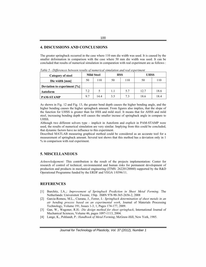
angle (β), where dw = 110 mm for UHSS. Comparisons of each springback amount depending on bending depth for individual material are illustrated on Fig. 17 and Fig. 18.
Fig. 12 - Springback (β) for different steels depending on bending depth (bd), where dw =
50 mm.
Fig. 13 - Springback (β) for different steels
depending on bending depth (bd), where dw = 110 mm.
100
Journal for Technology of Plasticity, Vol. 37 (2012), Number 1
4. DISCUSSIONS AND CONCLUSIONS
The greater springback occurred in the case where 110 mm die width was used. It is caused by the smaller deformation in comparison with the case where 50 mm die width was used. It can be concluded that results of numerical simulation in comparation with real experiment are as follows : Table 5 - Differences between results of numerical simulation and real experiment
Category of steel Mild Steel HSS UHSS
Die width [mm] 50 110 50 110 50 110
Deviation to experiment [%]
Autoform 7.2 5 1.1 5.7 12.7 18.6
PAM-STAMP 9.7 14.4 3.5 7.3 18.6 18.4 As shown in Fig. 12 and Fig. 13, the greater bend depth causes the higher bending angle, and the higher bending causes the higher springback amount. From figures also implies, that the slope of the function for UHSS is greater than for HSS and mild steel. It means that for AHSS and mild steel, increasing bending depth will causes the smaller incrase of springback angle in compare to UHSS. Although two different solvers type – implicit in Autoform and explicit in PAM-STAMP were used, the results of numerical simulation are very similar. Implying from this could be concluded, that dynamic factors have no influence to this experiment. Described MATLAB measuring graphical method could be considered as an accurate tool for a measurement of springback amount. Several test shows that this method has a deviation only in 1 % in comparison with real experiment. 5. MISCELLANEOUS Acknowledgement: This contribution is the result of the projects implementation: Center for research of control of technical, environmental and human risks for permanent development of production and products in mechanical engineering (ITMS: 26220120060) supported by the R&D Operational Programme funded by the ERDF and VEGA 1/0396/11. REFERENCES [1] Burchitz, I.A.,: Improvement of Springback Prediction in Sheet Metal Forming. The
Netherlands: Universiteit Twente, 156p. ISBN 978-90-365-2656-2, 2008 [2] Garcia-Romeu, M.L., Ciurana, J., Ferrer, I.: Springback determination of sheet metals in an
air bending process based on an experimental work, Journal of Materials Processing Technology, Volume 191, Issues 1-3, 1, Pages 174-177, 2009.
[3] Gan, W., Wagoner, R.H.: Die design method for sheet springback, International Journal of Mechanical Sciences, Volume 46, pages 1097-1113, 2004.
[4] Lange, K., Pohlandt, P.: Handbook of Metal Forming, McGraw-Hill, New York, 1985.
101
Journal for Technology of Plasticity, Vol. 37 (2012), Number 1
[5] Society of Manufacturing Engineers, D.B. Dallas and American Society of Tool and Manufacturing Engineers, Tool and Manufacturing Engineers Handbook: A ReferenceWork for Manufacturing Engineers, McGraw-Hill, New York, 1976.
[6] Sachs. G.: Principles and Methods of Sheet-Metal Fabricating, Reinhold Pub., New York, 1951.
[7] Livatyli, H., Altan, T.: Prediction and elimination of springback in straight flanging using computer aided design methods, Journal of Material processing Technology, Volume 117, p. 262–8, 2001.
[8] Ling, Y., Lee, H., Cheok, B.: Finite element analysis of springback in L-bending of sheet metals, Journal of Material Process and Technology, 168, 296–302, 2005.
[9] Gau, J.T., Kinzel, G.L.: A new model for springback prediction in which the Bauschinger effect is considered, International Journal of Mechanical Sciences, Volume 43, p. 1813–32, 2001.
[10] Gau, J.T., Kinzel, G.L.: An experimental investigation of te influence of the Bauschinger effect on springback prediction, Journal of Material Process and Technology, Volume 108, p. 369–75, 2001.
[11] Albut, A., Brabie, G.: The influence of the rolling direction of the joined steel sheets on the springback intensity in the cas of Ω-shape parts made from tailor welded strips, Archives of civil and mechanical engineering, Volume VI, Pages 5-12, 2006.
[12] Rèche, D., Besson, J., Sturel, T., Lemoine, X., Gourgues-Lorenzon, A.F.: Analysis of the air bending test using finite-element simulation: Application to steel sheets, International Journal of Mechanical Sciences, Volume 57, Issue 1, Pages 43-53, April 2012.
[13] Roll, K..: Simulation of Sheet Metal Forming – Necessary Developments in the Future. In: Numisheet 2008. p. 3-11. September 2008. Interlaken - Switzerland.
[14] Frącz. W., Stachowicz, F.: Springback phenomenom in sheet metal V-die air bending experimental and numerical study, Manufacturing and industrial engineering, Volume 7, p. 4-37, 2008.
[15] Zhiying, CH., Xianghuai, D.: The GTN damage model based on Hill’48 anisotropic yield criterion and its application in sheet metal forming, Computational Materials Science, Volume 44, Issue 3, Pages 1013-1021, 2009.
[16] Banabic, D.: Sheet Metal Forming Processes. Constitutive Modeling and Numerical Simulation. Springer. 2010. ISBN : 978-3-540-88112-4.
[17] Isaac Samuel, E., Choudhary, B.K.: Universal scaling of work hardening parameters in type 316L(N) stainless steel, Materials Science and Engineering: A, Volume 527, Issues 27–28, Pages 7457-7460, 2010.
[18] RECOMMENDATION FOR USERS OF PAMSTAMP 2G. 24-02-2009. Brojova 2113/16 32600. Appendixes of user’s guide Last update. MECAS ESI Company. Plzen. 18s.
[19] Kardes Sever, N., et al.: Springback Prediction in Bending of AHSS-DP-780, The Ohio State University. In: Proceedings of NAMRI/SME, Vol. 40, 2012.
[20] De Vin, L. J.: Curvature prediction in air bending of sheet metals, Journal of Materials Processing Technology, Volume 100, Issues 1–3, 3, Pages 257-261, 2000.
[21] Davies, G.: Chapter 3 - Materials for consideration and use in automotive body structures, Materials for Automobile Bodies, Butterworth-Heinemann, Pages 93–143, Oxford, 2012.
[22] Wijlen, E.V.: Optimisation of deep drawing process with experimental validation, University of Twente, 2007, 176 p., Twente.
[23] Bressan, J.D., et al.: A numerical simulation study of deep drawing testing and experuimental results of steel sheets, using a commercial software, The international journal of material forming, Vol. 3, Pages: 231-234, Springer, 2010.

102
Journal for Technology of Plasticity, Vol. 37 (2012), Number 1
[24] Panthi, S.K., Ramakrishnan, N.: Semi analytical modeling of springback in arc bending and effect of forming load, Trans.Nonferrous Met. Soc. China 21, 2276-2284, 2011.
[25] Osman, M.A., Shazly, M., El-Mokaddem, A., Wifi, A.S.: Springback prediction in V-die bending: modelling and experimentation, Journal of Achievements in Materials and Manufacturing Engineering, Vol. 38, No. 2, 179-186, 2010.
103
Journal for Technology of Plasticity, Vol. 37 (2012), Number 1
ODREĐIVANJE VELIČINE ELASTIČNOG VRAĆANJA U PROCESIMA OBRADE LIMA
Slota Ján, Jurčišin Miroslav
Department of Technologies and Materials, Faculty of Mechanical Engineering, Technical
University of Košice, Slovakia
REZIME Cilj ovog rada je određivanje elastičnog vraćanja limova u raznim slučajevima u procesima slobodnog savijanja. Praktični deo sastojao se iz dva dela. Prvi deo je vezan za eksperiment slobodnog savijanja za tri različite vrste čelika, različite iznose savijanja i različite geometrije alata. Uticaj ovih tehnoloških varijabli je ilustrovan i upoređen sa rezultatima numeričkih simulacija. Za simulacije su korišćeni implicit i eksplicit komercijalni kodovi. Ovaj rad koristi savremeni metodu merenja u okviru MATLAB sistema. Ključne reči: metoda konačnih elemenata, slobodno savijanje, AutoForm, Pam-Stamp, elastično vraćanje