Embed Size (px)
Citation preview
SPRING RIDERSDATE: 11/02/2012
Page 1
INSTALLATION GUIDELINES
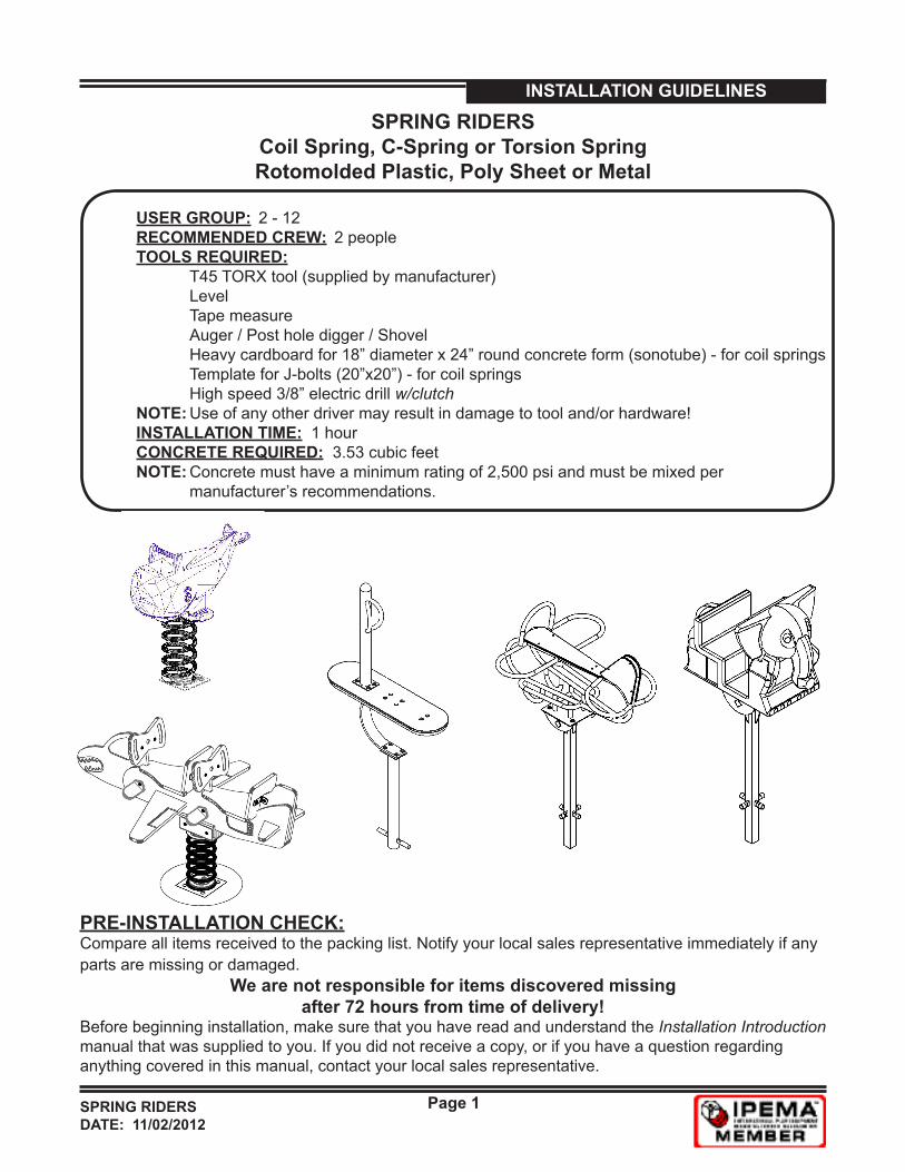
SPRING RIDERSCoil Spring, C-Spring or Torsion SpringRotomolded Plastic, Poly Sheet or Metal
PRE-INSTALLATION CHECK:Compare all items received to the packing list. Notify your local sales representative immediately if any parts are missing or damaged.
We are not responsible for items discovered missing after 72 hours from time of delivery!
Before beginning installation, make sure that you have read and understand the Installation Introduction manual that was supplied to you. If you did not receive a copy, or if you have a question regarding anything covered in this manual, contact your local sales representative.
USER GROUP: 2 - 12 RECOMMENDED CREW: 2 people TOOLS REQUIRED: T45 TORX tool (supplied by manufacturer) Level Tape measure Auger / Post hole digger / Shovel Heavy cardboard for 18” diameter x 24” round concrete form (sonotube) - for coil springs Template for J-bolts (20”x20”) - for coil springs High speed 3/8” electric drill w/clutch NOTE: Use of any other driver may result in damage to tool and/or hardware! INSTALLATION TIME: 1 hour CONCRETE REQUIRED: 3.53 cubic feet NOTE: Concrete must have a minimum rating of 2,500 psi and must be mixed per manufacturer’s recommendations.
SPRING RIDERSDATE: 11/02/2012
Page 2
INSTALLATION GUIDELINES
STEP 1 Refer to PLAN VIEW and FOOTING LAYOUT to locate spring rider.
STEP 2Excavate footing as shown in FOOTING LAYOUT and FOOTING ELEVATION. Place a 2” spacer in bottom of hole.
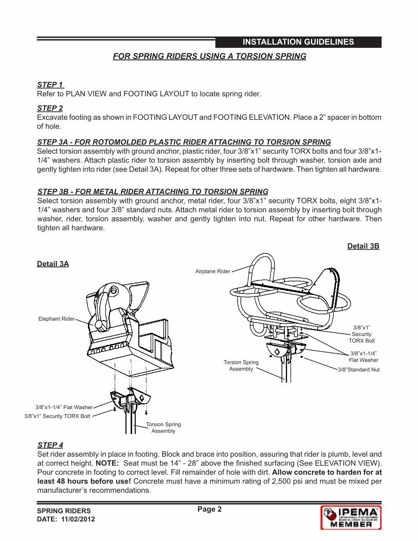
STEP 3A - FOR ROTOMOLDED PLASTIC RIDER ATTACHING TO TORSION SPRINGSelect torsion assembly with ground anchor, plastic rider, four 3/8”x1” security TORX bolts and four 3/8”x1-1/4” washers. Attach plastic rider to torsion assembly by inserting bolt through washer, torsion axle and gently tighten into rider (see Detail 3A). Repeat for other three sets of hardware. Then tighten all hardware.
STEP 4Set rider assembly in place in footing. Block and brace into position, assuring that rider is plumb, level and at correct height. NOTE: Seat must be 14” - 28” above the finished surfacing (See ELEVATION VIEW). Pour concrete in footing to correct level. Fill remainder of hole with dirt. Allow concrete to harden for at least 48 hours before use! Concrete must have a minimum rating of 2,500 psi and must be mixed per manufacturer’s recommendations.
FOR SPRING RIDERS USING A TORSION SPRING
STEP 3B - FOR METAL RIDER ATTACHING TO TORSION SPRINGSelect torsion assembly with ground anchor, metal rider, four 3/8”x1” security TORX bolts, eight 3/8”x1-1/4” washers and four 3/8” standard nuts. Attach metal rider to torsion assembly by inserting bolt through washer, rider, torsion assembly, washer and gently tighten into nut. Repeat for other hardware. Then tighten all hardware.
Detail 3A
Detail 3B
3/8”x1” Security TORX Bolt3/8”x1-1/4” Flat Washer
3/8”x1” Security
TORX Bolt
3/8”x1-1/4” Flat Washer
3/8”Standard Nut
Airplane Rider
Torsion Spring Assembly
Elephant Rider
Torsion Spring Assembly
SPRING RIDERSDATE: 11/02/2012
Page 3
INSTALLATION GUIDELINES
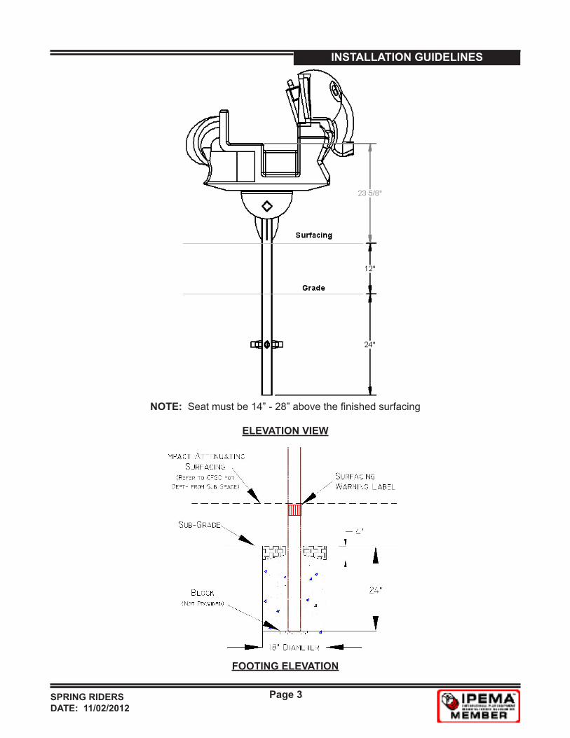
FOOTING ELEVATION
ELEVATION VIEW
NOTE: Seat must be 14” - 28” above the finished surfacing
SPRING RIDERSDATE: 11/02/2012
Page 4
INSTALLATION GUIDELINESFOR SPRING RIDERS USING A C-SPRING
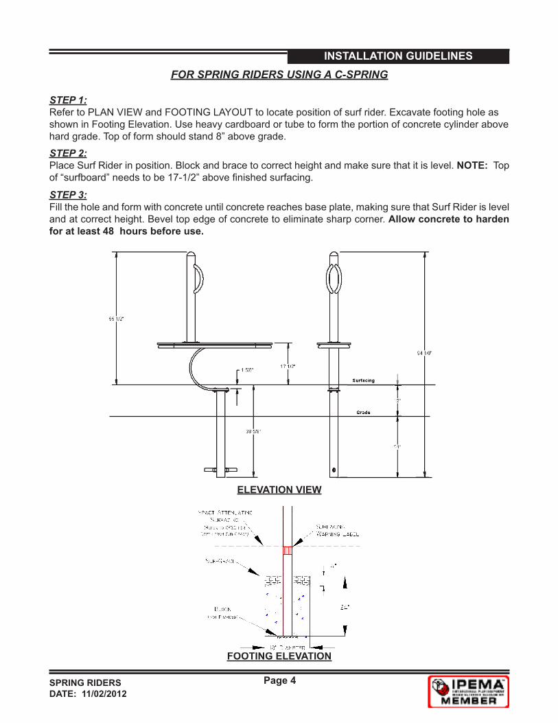
STEP 1:Refer to PLAN VIEW and FOOTING LAYOUT to locate position of surf rider. Excavate footing hole as shown in Footing Elevation. Use heavy cardboard or tube to form the portion of concrete cylinder above hard grade. Top of form should stand 8” above grade.
STEP 2: Place Surf Rider in position. Block and brace to correct height and make sure that it is level. NOTE: Top of “surfboard” needs to be 17-1/2” above finished surfacing.
STEP 3: Fill the hole and form with concrete until concrete reaches base plate, making sure that Surf Rider is level and at correct height. Bevel top edge of concrete to eliminate sharp corner. Allow concrete to harden for at least 48 hours before use.
ELEVATION VIEW
FOOTING ELEVATION
SPRING RIDERSDATE: 11/02/2012
Page 5
INSTALLATION GUIDELINES
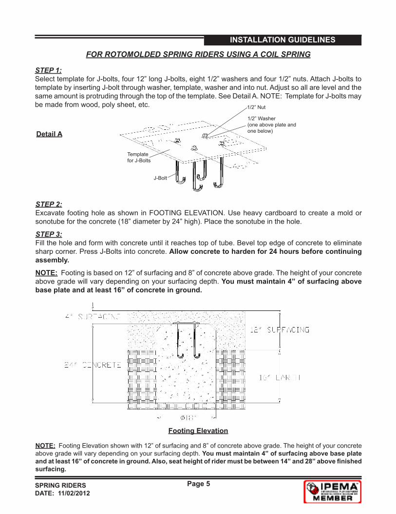
STEP 1: Select template for J-bolts, four 12” long J-bolts, eight 1/2” washers and four 1/2” nuts. Attach J-bolts to template by inserting J-bolt through washer, template, washer and into nut. Adjust so all are level and the same amount is protruding through the top of the template. See Detail A. NOTE: Template for J-bolts may be made from wood, poly sheet, etc.
FOR ROTOMOLDED SPRING RIDERS USING A COIL SPRING
J-Bolt
Template for J-Bolts
1/2” Nut
1/2” Washer(one above plate and one below)Detail A
STEP 3: Fill the hole and form with concrete until it reaches top of tube. Bevel top edge of concrete to eliminate sharp corner. Press J-Bolts into concrete. Allow concrete to harden for 24 hours before continuing assembly.
STEP 2: Excavate footing hole as shown in FOOTING ELEVATION. Use heavy cardboard to create a mold or sonotube for the concrete (18” diameter by 24” high). Place the sonotube in the hole.
Footing Elevation
NOTE: Footing Elevation shown with 12” of surfacing and 8” of concrete above grade. The height of your concrete above grade will vary depending on your surfacing depth. You must maintain 4” of surfacing above base plate and at least 16” of concrete in ground. Also, seat height of rider must be between 14” and 28” above finished surfacing.
NOTE: Footing is based on 12” of surfacing and 8” of concrete above grade. The height of your concrete above grade will vary depending on your surfacing depth. You must maintain 4” of surfacing above base plate and at least 16” of concrete in ground.
SPRING RIDERSDATE: 11/02/2012
Page 6
INSTALLATION GUIDELINES
STEP 4: Select rider, spring assembly, four 3/8”x1” TORX head bolts and four 3/8”x1-1/4” flat washers. Align holes in top plate with holes in rider. NOTE: The end plate with the largest holes will attach to the rider - plate with smallest holes attaches to concrete. Attach spring to rider by inserting bolt through washer and into rider. Gently tighten until all hardware is installed - then tighten all.
STEP 5: Detach template from concrete. NOTE: Installer may choose to provide four additional 1/2” nuts to install on J-Bolts before rider is attached to act as leveling nuts. Slide holes in base plate over J-bolts in concrete and install and tighten nuts on top of base plate.
STEP 6: Select rider assembly. Align holes in bottom plate with J-bolts in concrete. Set rider in place. Secure rider to concrete using hardware removed in Step 5. Gently tighten until all hardware is installed. Then tighten all. NOTE: May have to use leveling nuts or shims under bottom plate to level rider.
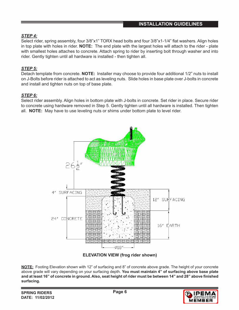
ELEVATION VIEW (frog rider shown)
NOTE: Footing Elevation shown with 12” of surfacing and 8” of concrete above grade. The height of your concrete above grade will vary depending on your surfacing depth. You must maintain 4” of surfacing above base plate and at least 16” of concrete in ground. Also, seat height of rider must be between 14” and 28” above finished surfacing.
SPRING RIDERSDATE: 11/02/2012
Page 7
INSTALLATION GUIDELINES
FOR POLY SHEET SPRING RIDERS USING A COIL SPRING
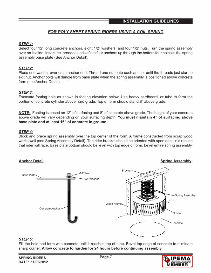
STEP 1: Select four 12” long concrete anchors, eight 1/2” washers, and four 1/2” nuts. Turn the spring assembly over on its side. Insert the threaded ends of the four anchors up through the bottom four holes in the spring assembly base plate (See Anchor Detail).
STEP 2: Place one washer over each anchor end. Thread one nut onto each anchor until the threads just start to exit nut. Anchor bolts will dangle from base plate when the spring assembly is positioned above concrete form (see Anchor Detail).
Anchor Detail
Concrete Anchor
Base Plate 1/2” Nut
1/2” Washer
Spring Assembly
Wood Frame
Spring Assembly
Concrete
Form
Bracket
STEP 3: Excavate footing hole as shown in footing elevation below. Use heavy cardboard, or tube to form the portion of concrete cylinder above hard grade. Top of form should stand 8” above grade.
STEP 4: Block and brace spring assembly over the top center of the form. A frame constructed from scrap wood works well (see Spring Assembly Detail). The rider bracket should be oriented with open ends in direction that rider will face. Base plate bottom should be level with top edge of form. Level entire spring assembly.
STEP 5: Fill the hole and form with concrete until it reaches top of tube. Bevel top edge of concrete to eliminate sharp corner. Allow concrete to harden for 24 hours before continuing assembly.
NOTE: Footing is based on 12” of surfacing and 8” of concrete above grade. The height of your concrete above grade will vary depending on your surfacing depth. You must maintain 4” of surfacing above base plate and at least 16” of concrete in ground.
SPRING RIDERSDATE: 11/02/2012
Page 8
INSTALLATION GUIDELINES
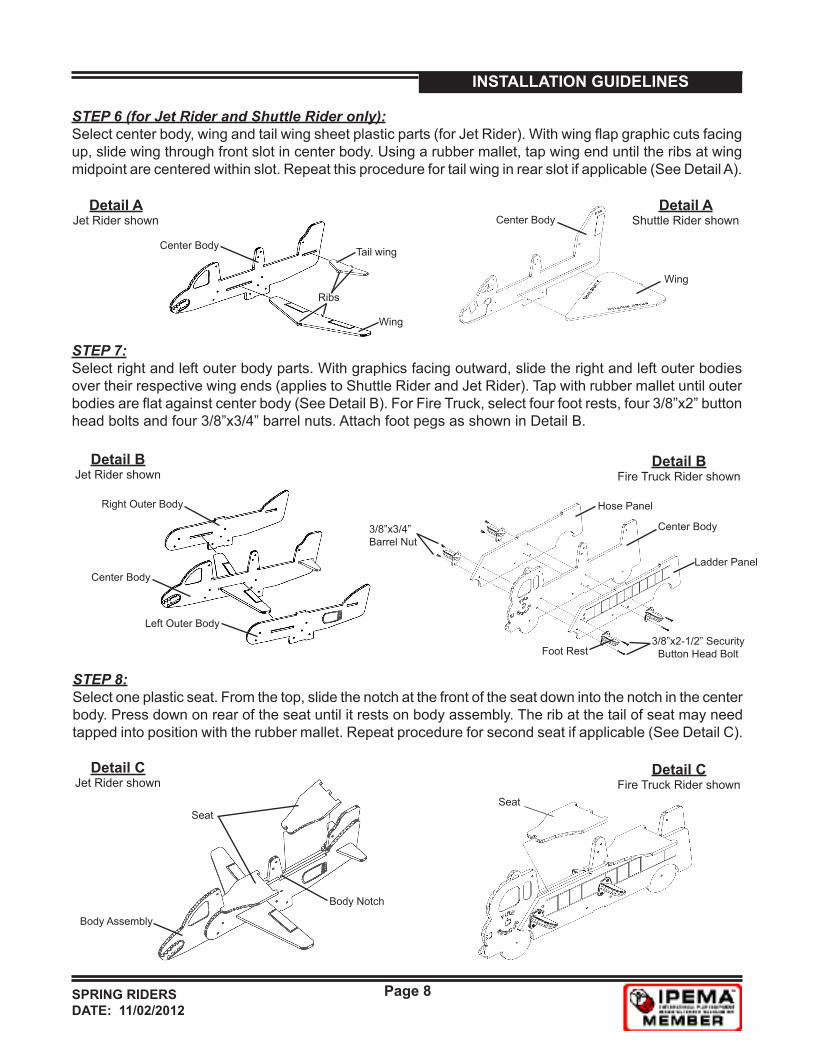
STEP 6 (for Jet Rider and Shuttle Rider only): Select center body, wing and tail wing sheet plastic parts (for Jet Rider). With wing flap graphic cuts facing up, slide wing through front slot in center body. Using a rubber mallet, tap wing end until the ribs at wing midpoint are centered within slot. Repeat this procedure for tail wing in rear slot if applicable (See Detail A).
Detail AJet Rider shown
Ribs
Wing
Tail wingCenter Body
STEP 7: Select right and left outer body parts. With graphics facing outward, slide the right and left outer bodies over their respective wing ends (applies to Shuttle Rider and Jet Rider). Tap with rubber mallet until outer bodies are flat against center body (See Detail B). For Fire Truck, select four foot rests, four 3/8”x2” button head bolts and four 3/8”x3/4” barrel nuts. Attach foot pegs as shown in Detail B.
Detail BJet Rider shown
Center Body
Right Outer Body
Left Outer Body
STEP 8: Select one plastic seat. From the top, slide the notch at the front of the seat down into the notch in the center body. Press down on rear of the seat until it rests on body assembly. The rib at the tail of seat may need tapped into position with the rubber mallet. Repeat procedure for second seat if applicable (See Detail C).
Seat
Body Assembly
Body Notch
Center Body
Hose Panel
Ladder Panel
Foot Rest
3/8”x3/4” Barrel Nut
3/8”x2-1/2” Security Button Head Bolt
Detail BFire Truck Rider shown
Seat
Detail AShuttle Rider shown
Wing
Center Body
Detail CJet Rider shown
Detail CFire Truck Rider shown
SPRING RIDERSDATE: 11/02/2012
Page 9
INSTALLATION GUIDELINES
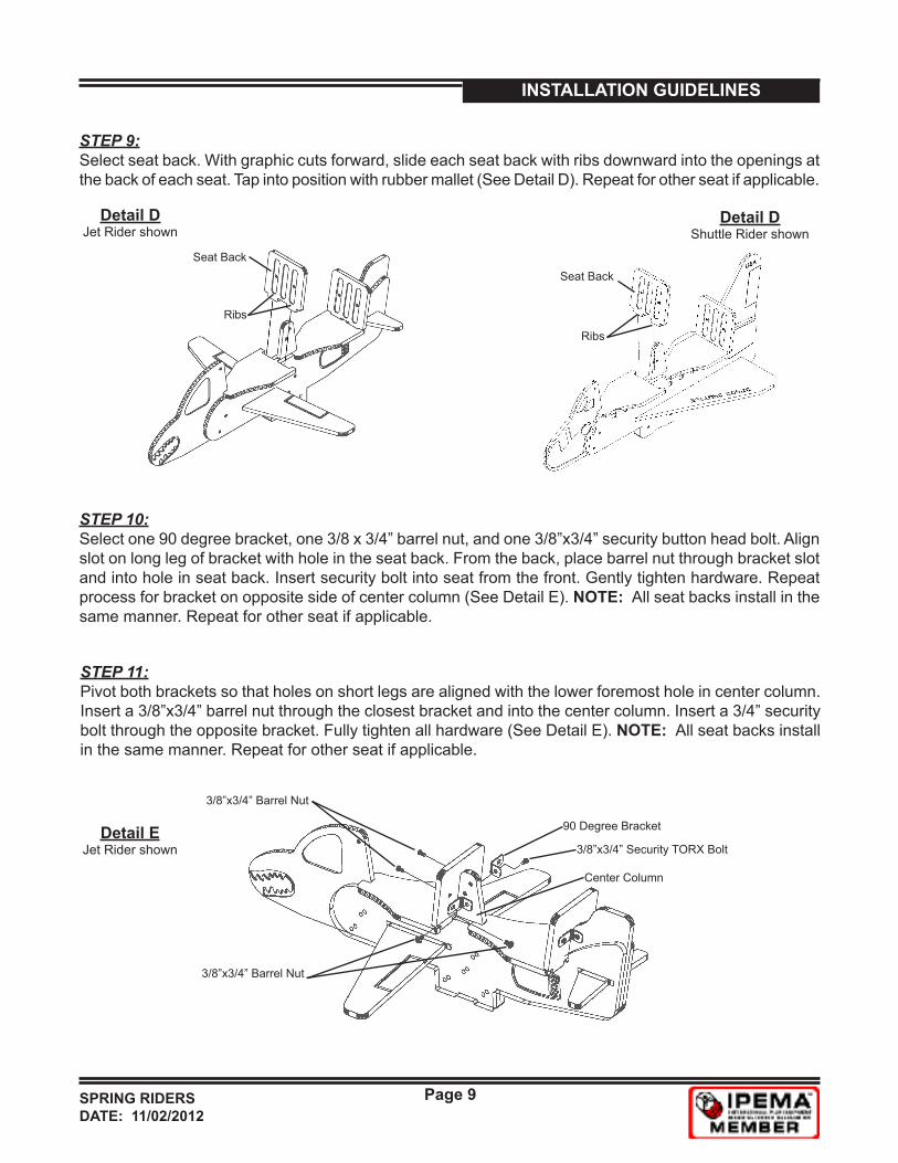
STEP 9:Select seat back. With graphic cuts forward, slide each seat back with ribs downward into the openings at the back of each seat. Tap into position with rubber mallet (See Detail D). Repeat for other seat if applicable.
Ribs
Seat Back
STEP 10: Select one 90 degree bracket, one 3/8 x 3/4” barrel nut, and one 3/8”x3/4” security button head bolt. Align slot on long leg of bracket with hole in the seat back. From the back, place barrel nut through bracket slot and into hole in seat back. Insert security bolt into seat from the front. Gently tighten hardware. Repeat process for bracket on opposite side of center column (See Detail E). NOTE: All seat backs install in the same manner. Repeat for other seat if applicable.
STEP 11: Pivot both brackets so that holes on short legs are aligned with the lower foremost hole in center column. Insert a 3/8”x3/4” barrel nut through the closest bracket and into the center column. Insert a 3/4” security bolt through the opposite bracket. Fully tighten all hardware (See Detail E). NOTE: All seat backs install in the same manner. Repeat for other seat if applicable.
Detail EJet Rider shown 3/8”x3/4” Security TORX Bolt
3/8”x3/4” Barrel Nut
90 Degree Bracket
3/8”x3/4” Barrel Nut
Center Column
Ribs
Seat Back
Detail DJet Rider shown
Detail DShuttle Rider shown
SPRING RIDERSDATE: 11/02/2012
Page 10
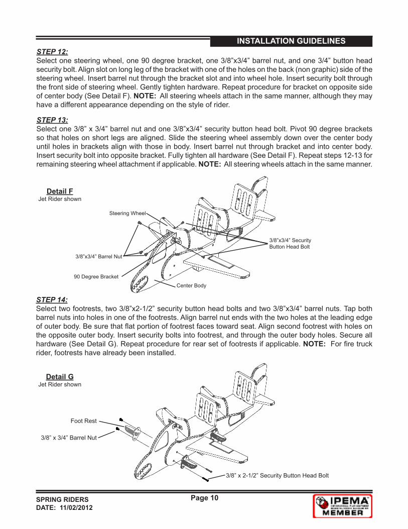
INSTALLATION GUIDELINESSTEP 12: Select one steering wheel, one 90 degree bracket, one 3/8”x3/4” barrel nut, and one 3/4” button head security bolt. Align slot on long leg of the bracket with one of the holes on the back (non graphic) side of the steering wheel. Insert barrel nut through the bracket slot and into wheel hole. Insert security bolt through the front side of steering wheel. Gently tighten hardware. Repeat procedure for bracket on opposite side of center body (See Detail F). NOTE: All steering wheels attach in the same manner, although they may have a different appearance depending on the style of rider.
Detail FJet Rider shown
3/8”x3/4” Barrel Nut
3/8”x3/4” SecurityButton Head Bolt
90 Degree Bracket
STEP 13: Select one 3/8” x 3/4” barrel nut and one 3/8”x3/4” security button head bolt. Pivot 90 degree brackets so that holes on short legs are aligned. Slide the steering wheel assembly down over the center body until holes in brackets align with those in body. Insert barrel nut through bracket and into center body. Insert security bolt into opposite bracket. Fully tighten all hardware (See Detail F). Repeat steps 12-13 for remaining steering wheel attachment if applicable. NOTE: All steering wheels attach in the same manner.
Steering Wheel
Center Body
STEP 14: Select two footrests, two 3/8”x2-1/2” security button head bolts and two 3/8”x3/4” barrel nuts. Tap both barrel nuts into holes in one of the footrests. Align barrel nut ends with the two holes at the leading edge of outer body. Be sure that flat portion of footrest faces toward seat. Align second footrest with holes on the opposite outer body. Insert security bolts into footrest, and through the outer body holes. Secure all hardware (See Detail G). Repeat procedure for rear set of footrests if applicable. NOTE: For fire truck rider, footrests have already been installed.
3/8” x 2-1/2” Security Button Head Bolt
Foot Rest
3/8” x 3/4” Barrel Nut
Detail GJet Rider shown
SPRING RIDERSDATE: 11/02/2012
Page 11
INSTALLATION GUIDELINES
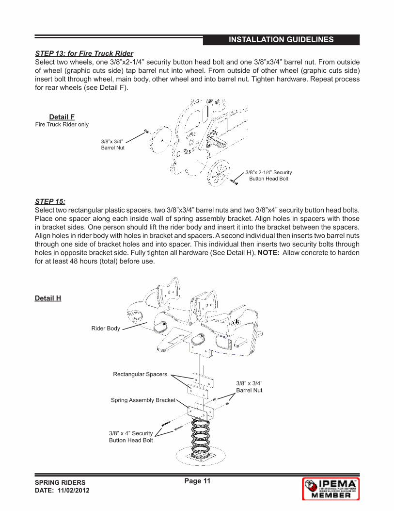
STEP 15: Select two rectangular plastic spacers, two 3/8”x3/4” barrel nuts and two 3/8”x4” security button head bolts. Place one spacer along each inside wall of spring assembly bracket. Align holes in spacers with those in bracket sides. One person should lift the rider body and insert it into the bracket between the spacers. Align holes in rider body with holes in bracket and spacers. A second individual then inserts two barrel nuts through one side of bracket holes and into spacer. This individual then inserts two security bolts through holes in opposite bracket side. Fully tighten all hardware (See Detail H). NOTE: Allow concrete to harden for at least 48 hours (total) before use.
3/8” x 4” Security Button Head Bolt
Rider Body
Spring Assembly Bracket
3/8” x 3/4”Barrel Nut
Rectangular Spacers
Detail H
Detail FFire Truck Rider only
STEP 13: for Fire Truck Rider Select two wheels, one 3/8”x2-1/4” security button head bolt and one 3/8”x3/4” barrel nut. From outside of wheel (graphic cuts side) tap barrel nut into wheel. From outside of other wheel (graphic cuts side) insert bolt through wheel, main body, other wheel and into barrel nut. Tighten hardware. Repeat process for rear wheels (see Detail F).
3/8”x 3/4” Barrel Nut
3/8”x 2-1/4” Security Button Head Bolt


![Licensing MotorcycleRiders’ Handbookironbrothersmc.com/motors/[Riders' book]/Riders' handbook.pdf · MotorcycleRiders’ Handbook. Motorcycle Riders’ Handbook Learner Approved](https://img.pdfslide.us/doc/110x75/5a7801147f8b9ad22a8e985c/licensing-motorcycleriders-ha-riders-bookriders-handbookpdf-motorcycleriders.jpg)