Embed Size (px)
Citation preview
Vol 13, No. 1, 2002 1 HYDROGEN TODAY
Official Publication of the American Hydrogen Association•1739 W. 7th Ave Mesa, AZ 85202-1906
THE BEAULIEU HYDROGEN HOME
Grey water will be utilized to irrigate plants that grow on 30” of soil that combines green roofing and thermal flywheels for the multi-level living ar-eas. Biomass collected from the green roofs that help control solar gain to cool the home in the sum-mer and warm the home in the winter will be used along with black water to produce hydrogen.
Hydrogen will also be produced by pressurizing electrolysis using energy supplied by photovoltaic panels and by generators that are integrated into unique exercise machines that help the Beaulieu family stay fit. Friends and visitors will be welcome participants on the exercisers.
Hydrogen will be stored for applications ranging from powering family vehicles that clean the air to unique engine-generators that make electricity, cook food, and produce distilled water. Oxygen will be utilized to freshen air, for grey-water purifica-tion, to support fish farming, and for medicinal uses by neighbors and area hospitals.
Bryan and Yvette plan to utilize their home as a living laboratory of inspired concepts and research projects that have promise for overcoming the prob-lems of resource depletion and pollution.
They have designed an exciting home with care-ful elimination of the materials that outgas un-wanted odors and adverse chemicals. Their Hydro-gen Home is designed to overcome the syndrome of many highly insulated structures that do not breathe adequately to avoid having “bottled-up” air pollu-tion that can often be measured to be more concen-trated and harmful than the infamous smog that plagues cities. Their hydrogen-powered cars will clean the air outside their home even as they take great care to have very clean and healthful air inside their home.
Please ask Mr. and Mrs. Beaulieu to adopt me! This repeated request comes from primary to gradu-ate school students when they learn about the hydro-gen home that Bryan and Yvette Beaulieu are build-ing. It is the type of endorsement that is shared by community planners and other homeowners that learn about the emerging plans for the Beaulieu Family Hydrogen Home.
The new Beaulieu Hydrogen Home is designed to complement the boulders and natural beauty of Troon Mountain in north Scottsdale, Arizona. The five-acre lot that Bryan and Yvette chose overlooks Phoenix, Scottsdale and Paradise Valley and slopes from high on the mountain to the road that forms the southern border of the property. After careful study of the lot, Bryan has designed their home as a com-plement to the natural landscape that will be care-fully preserved.
Bryan Beaulieu is a very talented inventor and engineer who has turned his attention to building a remarkable home for his family. The Beaulieu Hy-drogen Home is being designed as the world’s first dwelling that features “minus-emissions” impact on the occupants and the environment. This means that the Beaulieu home will remove pollutants that ordi-narily contaminate the air, water, and soil as it pro-vides shelter, pleasant exercise, multipurpose gar-dening, and comfortable living conditions.
Rain water collected from the five acre lot will be saved and cascaded in series and parallel circuits through a variety of purposes ranging from water-falls that scrub and condition air that is circulated through living areas, for thermal-energy banking, water recreation, hydroponics, and to support aquatic plants and creatures.
Roy McAlister
Vol 13, No. 1, 2002 2 HYDROGEN TODAY
ABSTRACT
This paper describes the details of converting a gasoline powered 427 Shelby Cobra to run on gase-ous hydrogen. The purpose of this project was to de-sign a vehicle capable of beating the current land speed record for hydrogen powered vehicles.
The vehicle uses a modified 427 Ford FE engine as the power plant with a specially designed electronic fuel injection system for metering the hydrogen. The engine was designed to produce near zero emissions (<10 ppm NOx) at approximately 270 HP using a lean burn, “quality controlled”, fueling strategy (no pollution control devices are utilized). INTRODUCTION
In the early 1990’s, a long time hydrogen advocate named Ben Jordan built a trophy to be given each year to the fastest hydrogen powered vehicle. The competition is held at the Bonneville Salt Flats in Utah. The current record for this competition is 108.268 mph held by AHA member, Terry Young of Middle Tennessee State University. Since there is currently no official class for hydrogen fueled vehi-cles, the vehicles are run in what is called a “time only” category 1). The goal was to build a vehicle ca-pable of beating that record and win the Ben Jordan trophy.
BACKGROUND Hydrogen is widely regarded as a promising transpor-tation fuel because it is clean, abundant, and renew-able. In a gaseous state, it is colorless, odorless, and non-toxic. When hydrogen is combusted with oxygen, it forms water as the by-product. Due to hydrogen’s high flammability range, it can be completely com-busted over a wide range of air/fuel ratios. Unlike gasoline, which if combusted outside its optimal air/fuel ratio will produce excess carbon monoxide (CO)
and hydrocarbons (HC), hydrogen does not have a carbon element and therefore will not produce those toxic gases. Like gasoline however, when hydrogen is combusted in air (mixture of oxygen and nitrogen) the temperature of combustion can cause the formation of the nitric oxidizes (NOx). Hydrogen however has an advantage over gasoline in this area because it can be combusted using very high air/fuel ratios. Using a high air/fuel ratio (i.e. combusting hydrogen with more air than is theoretically required) causes the combustion temperature to drop dramatically and thus causes a reduction in the formation of NOx. Unfortunately, the use of excess air also lowers the power output of the engine. [1]
Over the past eight years, the University of Cali-fornia – Riverside, College of Engineering – Center for Environmental Research and Technology (CE CERT) has been experimenting with improving the performance of hydrogen-powered vehicles. Most of these methods have involved using superchargers [2]
and turbochargers [3] to bring up the power. While these devices have worked to some degree, it was felt these methods were too complicated of a solution to a simple problem. The authors of this paper believed the simple solution was to just make the engine big-ger. Or use a car that has “way more en-gine” (Horsepower) than it really needs. The author of this paper chose the latter - and what better car for this than the Shelby Cobra? The Shelby Cobra
The Cobra was the brainchild of racecar driver, Carroll Shelby. In 1962, Shelby worked a deal with Britain’s AC Cars and America’s Ford Motor Com-pany to develop the quickest production vehicle in the world. Initially, street Cobras were powered by stock HiPo 260 Fords, but were soon replaced with HiPo 289s rated at 271 HP. In January 1963, the Cobra won
Hydrogen Powered Shelby Cobra: Vehicle Conversion
James W. Heffel University of California, Riverside, CE-CERT
Douglas C. Johnson Cal-Draulics
Carroll Shelby Carroll Shelby Enterprises
Vol 13, No. 1, 2002 3 HYDROGEN TODAY
Task 3. Install the roll cage and fire suppression system Task 4. Do a car and driver checkout run (on gaso line) at El Mirage Dry Lake Bed. Task 5. Convert the car to run on hydrogen. Task 6. Do a record attempt at Bonneville Salt Flats (Oct. 2000). With limited funds and limited time, the following set of conditions were developed: 1. Do it as simple as possible 2. Do it as quickly as possible 3. Do it as economically as possible (and still beat the record) Tasks 1, 2, and 3
The first order of business was to get the engine and transmission mated together and then installed this assembly into the car. Instead of the using a 4-speed “top loader” transmission originally used in the 1965 Cobras, a 5-speed Tremec TKO manual trans-mission was chosen. To comply with the Bonneville National rules, a steel shatter shield was required in place of the aluminum bellhousing. For this, a shatter shield made by Lakewood was used. To mate the shatter shield to the transmission, an adaptor plate, made by McLeod, was used. A Centerforce, double acting clutch and flywheel were employed to provide positive engagement between the engine and trans-mission. Wayne’s Engine Rebuilding, Inc. of River-side, California, balanced the clutch, disc, and fly-wheel. The clutch fork and throw out bearing, nor-mally used on 1970 Ford Broncos, was utilized to fi-nalize the transmission assembly.
To ease the installation of the transmission/engine, the radiator was removed and the engine/transmission assembly was carefully lowered into the car as a sin-gle unit. The transmission was secured to the chassis using a transmission mount (new) from a late model Ford Mustang and the engine was secured to the chas-sis using motor mounts from a 1965 Ford Galaxy Sta-tion Wagon (also new). To connect the output shaft of the transmission to the input shaft of the Dana 44 dif-ferential, Golden State Axle of Corona, California fabricated a special 13-inch long driveshaft.
Following the installation of the engine and trans-mission, the car was sent to the paint shop where Tony Avila, Tony, Jr. and Herman Broom gave it the flashy red paint job with two white racing stripes
its first race at the SCCA divisional race at Riverside Speedway. The racing legacy of Carroll Shelby’s Co-bra had begun. Over the next few years, the 289 Co-bra dominated the racing circuit. In January 1965, Shelby started the production of the 427 Cobra, which used a Ford 427 side-oiler. Although, the 289 was by far the biggest winner, whatever the 289 did, the 427 did better. The 427 Cobra was and remains the “world’s quickest production car”. That was proven with 0 – 60 mph times of 3.8 seconds, 0 – 100 mph in 10.6 seconds, and 0 – 100 and back to a dead stop in less than 14 seconds. [4]
In 1996 Shelby American, Inc. announced the rein-troduction of the Shelby 427 S/C Cobra as the CSX4000 component vehicle. The cars are sold as “rollers” (less the engine and transmission).
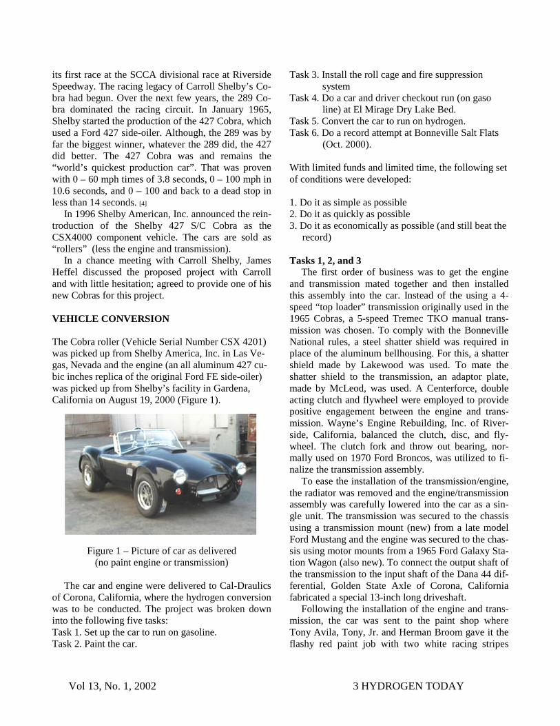
In a chance meeting with Carroll Shelby, James Heffel discussed the proposed project with Carroll and with little hesitation; agreed to provide one of his new Cobras for this project. VEHICLE CONVERSION The Cobra roller (Vehicle Serial Number CSX 4201) was picked up from Shelby America, Inc. in Las Ve-gas, Nevada and the engine (an all aluminum 427 cu-bic inches replica of the original Ford FE side-oiler) was picked up from Shelby’s facility in Gardena, California on August 19, 2000 (Figure 1).
Figure 1 – Picture of car as delivered (no paint engine or transmission)
The car and engine were delivered to Cal-Draulics
of Corona, California, where the hydrogen conversion was to be conducted. The project was broken down into the following five tasks: Task 1. Set up the car to run on gasoline. Task 2. Paint the car.
Vol 13, No. 1, 2002 4 HYDROGEN TODAY
down the center. Tony, Herman, and Tony, Jr. also assisted in the installation of the hydrogen storage tank. From the paint shop the car went back to Cal Draulics where a small gasoline tank was installed in the trunk of the car so it could be tested on gasoline to verify all the components (engine, transmission, clutch, brakes, etc) were operating properly. Once this was completed, the car went to Cook Motorsports in Norco, California, where the installation of the roll cage and fire suppression system was conducted. All these tasks were completed by October 7, 2000.
Task 4
On October 8, the car was taken to El Mirage Dry Lake Bed in the high desert of California to do a test run on gasoline. A speed of 135 mph was recorded with James Heffel driving. This was not a maximum speed run. This run was performed to verify that both the car and the driver were capable of operating at speeds above the current hydrogen record, prior to attempting this using hydrogen. Task 5
Hydrogen Fuel Injection System One of the primary problems encountered in the
development of operational hydrogen engines is pr mature ignition (pre-ignition). Pre -ignition occurs when the cylinder charge becomes ignited before the ignition by the spark plug. If this condition occurs when the intake valve is open, the flame can travel back into the induction system. Various fuel injection methods have been experimented with over the years. These methods have included carbureted systems, which mix the air and fuel at a central point upstream of the intake valves; port injection systems that inject the fuel into the air stream near the intake valve; and direct injection systems that inject the fuel directly into the combustion chamber. For carburetor-type systems, which can have a substantial amount of air and fuel in the manifold, pre-ignition can have a dev-astating effect. Port injection systems, which tend to have less fuel in the manifold at any one time, can minimize this effect. Running lean (excess air) and precisely timing the injector opening and closing times (tuning the system), can virtually eliminate pre-ignition from occurring. Direct injection system can eliminate pre-ignition in the intake manifold, however it does not necessarily eliminate it in the combustion chamber. Direct injection systems also require higher fuel pressure and tend to be a little more complicated
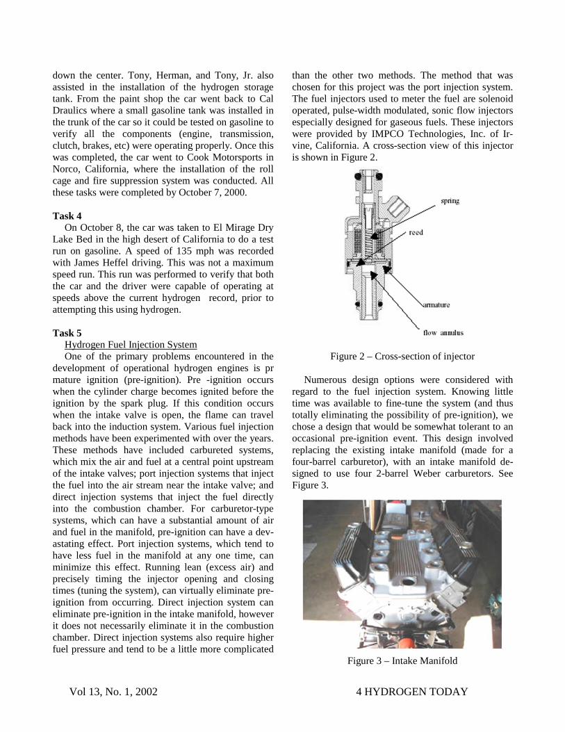
than the other two methods. The method that was chosen for this project was the port injection system. The fuel injectors used to meter the fuel are solenoid operated, pulse-width modulated, sonic flow injectors especially designed for gaseous fuels. These injectors were provided by IMPCO Technologies, Inc. of Ir-vine, California. A cross-section view of this injector is shown in Figure 2.
Figure 2 – Cross-section of injector
Numerous design options were considered with regard to the fuel injection system. Knowing little time was available to fine-tune the system (and thus totally eliminating the possibility of pre-ignition), we chose a design that would be somewhat tolerant to an occasional pre-ignition event. This design involved replacing the existing intake manifold (made for a four-barrel carburetor), with an intake manifold de-signed to use four 2-barrel Weber carburetors. See Figure 3.
Figure 3 – Intake Manifold
Vol 13, No. 1, 2002 5 HYDROGEN TODAY
This new manifold provided short, single runners for each cylinder. For each runner, a 1 ½ inch tall injector body was designed and fabricated to house the injec-tors. See Figure 4.
Figure 4 - Injector body
Each injector body was designed to incorporate a ¼ inch tube that transported the hydrogen from the injector outlet to within an inch of the intake valve. This was to minimize the amount of hydrogen that would be in contact with the air in the runner. That way if pre-ignition was to occur, damage to the intake system would negligible.
Additionally, a “quality” control fuel strategy was selected as the basis for metering the hydrogen. A dis-tinct advantage of using hydrogen as a fuel, with its wide range of flammability, is the fuel-to-air ratio or the “quality” of the charge mixture can easily be var-ied to meet different driving conditions or loads. This is similar to the strategy used by diesel engines. In contrast, for a gasoline engine, the fuel-to-air ratio must be kept more or less constant throughout the driving range. In other words, the “quantity” of the charge is controlled. Using a “quality” controlled strategy enables the engine to operate at a constant wide-open-throttle (WOT) position throughout the power band (just add more fuel for more torque). To communicate to the Engine Control Computer (ECC) the amount of fuel desired, a throttle position indica-tor was connected to the gas pedal (not to the throttle plates since they are normally at WOT). Basically the gas pedal acted as an electronic sensor that would send a fuel demand signal to the ECC. The ECC would base how long it would hold an injector open on this signal.
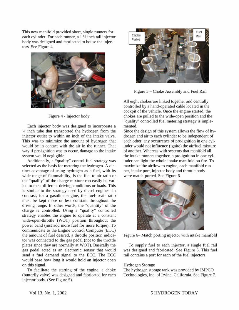
To facilitate the starting of the engine, a choke (butterfly valve) was designed and fabricated for each injector body. (See Figure 5).
Figure 5 – Choke Assembly and Fuel Rail All eight chokes are linked together and centrally controlled by a hand-operated cable located in the cockpit of the vehicle. Once the engine started, the chokes are pulled to the wide-open position and the “quality” controlled fuel metering strategy is imple-mented. Since the design of this system allows the flow of hy-drogen and air to each cylinder to be independent of each other, any occurrence of pre-ignition in one cyl-inder would not influence (ignite) the air/fuel mixture of another. Whereas with systems that manifold all the intake runners together, a pre-ignition in one cyl-inder can light the whole intake manifold on fire. To maximize the airflow to engine, each manifold run-ner, intake port, injector body and throttle body were match-ported. See Figure 6. Figure 6– Match porting injector with intake manifold
To supply fuel to each injector, a single fuel rail
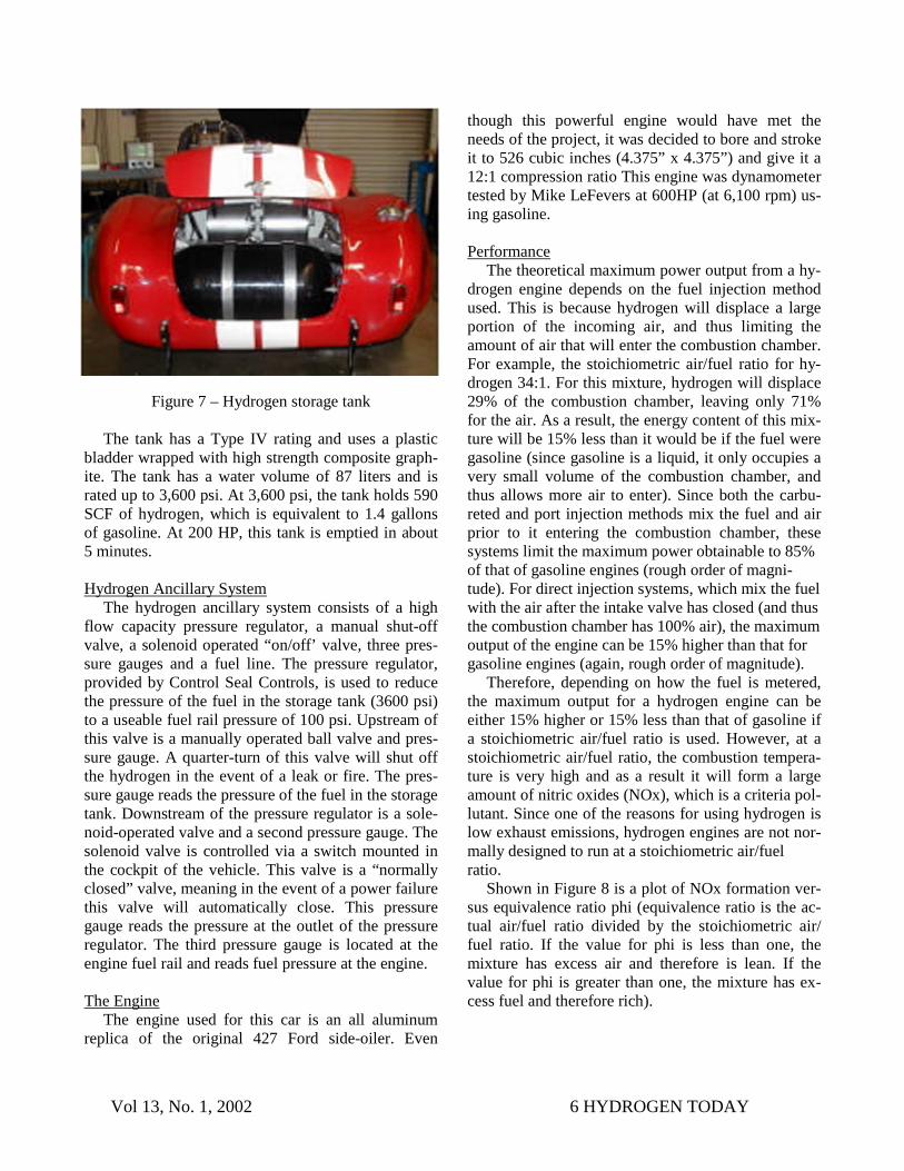
was designed and fabricated. See Figure 5. This fuel rail contains a port for each of the fuel injectors. Hydrogen Storage The hydrogen storage tank was provided by IMPCO Technologies, Inc. of Irvine, California. See Figure 7.
Vol 13, No. 1, 2002 6 HYDROGEN TODAY
Figure 7 – Hydrogen storage tank
The tank has a Type IV rating and uses a plastic bladder wrapped with high strength composite graph-ite. The tank has a water volume of 87 liters and is rated up to 3,600 psi. At 3,600 psi, the tank holds 590 SCF of hydrogen, which is equivalent to 1.4 gallons of gasoline. At 200 HP, this tank is emptied in about 5 minutes. Hydrogen Ancillary System
The hydrogen ancillary system consists of a high flow capacity pressure regulator, a manual shut-off valve, a solenoid operated “on/off’ valve, three pres-sure gauges and a fuel line. The pressure regulator, provided by Control Seal Controls, is used to reduce the pressure of the fuel in the storage tank (3600 psi) to a useable fuel rail pressure of 100 psi. Upstream of this valve is a manually operated ball valve and pres-sure gauge. A quarter-turn of this valve will shut off the hydrogen in the event of a leak or fire. The pres-sure gauge reads the pressure of the fuel in the storage tank. Downstream of the pressure regulator is a sole-noid-operated valve and a second pressure gauge. The solenoid valve is controlled via a switch mounted in the cockpit of the vehicle. This valve is a “normally closed” valve, meaning in the event of a power failure this valve will automatically close. This pressure gauge reads the pressure at the outlet of the pressure regulator. The third pressure gauge is located at the engine fuel rail and reads fuel pressure at the engine. The Engine
The engine used for this car is an all aluminum replica of the original 427 Ford side-oiler. Even
though this powerful engine would have met the needs of the project, it was decided to bore and stroke it to 526 cubic inches (4.375” x 4.375”) and give it a 12:1 compression ratio This engine was dynamometer tested by Mike LeFevers at 600HP (at 6,100 rpm) us-ing gasoline.
Performance
The theoretical maximum power output from a hy-drogen engine depends on the fuel injection method used. This is because hydrogen will displace a large portion of the incoming air, and thus limiting the amount of air that will enter the combustion chamber. For example, the stoichiometric air/fuel ratio for hy-drogen 34:1. For this mixture, hydrogen will displace 29% of the combustion chamber, leaving only 71% for the air. As a result, the energy content of this mix-ture will be 15% less than it would be if the fuel were gasoline (since gasoline is a liquid, it only occupies a very small volume of the combustion chamber, and thus allows more air to enter). Since both the carbu-reted and port injection methods mix the fuel and air prior to it entering the combustion chamber, these systems limit the maximum power obtainable to 85% of that of gasoline engines (rough order of magni-tude). For direct injection systems, which mix the fuel with the air after the intake valve has closed (and thus the combustion chamber has 100% air), the maximum output of the engine can be 15% higher than that for gasoline engines (again, rough order of magnitude).
Therefore, depending on how the fuel is metered, the maximum output for a hydrogen engine can be either 15% higher or 15% less than that of gasoline if a stoichiometric air/fuel ratio is used. However, at a stoichiometric air/fuel ratio, the combustion tempera-ture is very high and as a result it will form a large amount of nitric oxides (NOx), which is a criteria pol-lutant. Since one of the reasons for using hydrogen is low exhaust emissions, hydrogen engines are not nor-mally designed to run at a stoichiometric air/fuel ratio.
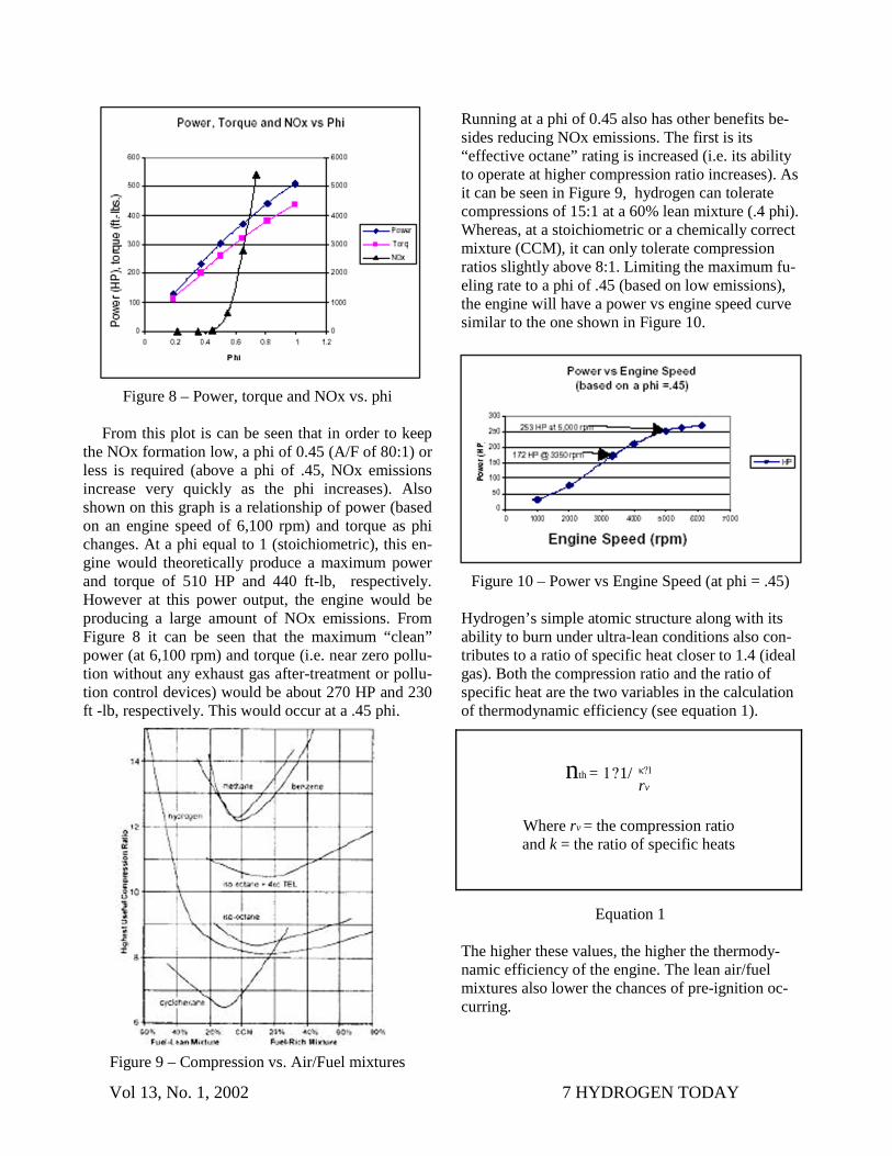
Shown in Figure 8 is a plot of NOx formation ver-sus equivalence ratio phi (equivalence ratio is the ac-tual air/fuel ratio divided by the stoichiometric air/fuel ratio. If the value for phi is less than one, the mixture has excess air and therefore is lean. If the value for phi is greater than one, the mixture has ex-cess fuel and therefore rich).
Vol 13, No. 1, 2002 7 HYDROGEN TODAY
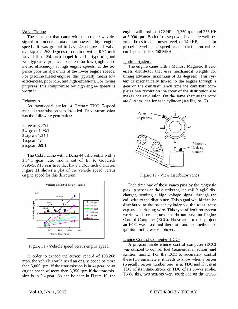
Running at a phi of 0.45 also has other benefits be-sides reducing NOx emissions. The first is its “effective octane” rating is increased (i.e. its ability to operate at higher compression ratio increases). As it can be seen in Figure 9, hydrogen can tolerate compressions of 15:1 at a 60% lean mixture (.4 phi). Whereas, at a stoichiometric or a chemically correct mixture (CCM), it can only tolerate compression ratios slightly above 8:1. Limiting the maximum fu-eling rate to a phi of .45 (based on low emissions), the engine will have a power vs engine speed curve similar to the one shown in Figure 10.
Figure 10 – Power vs Engine Speed (at phi = .45) Hydrogen’s simple atomic structure along with its ability to burn under ultra-lean conditions also con-tributes to a ratio of specific heat closer to 1.4 (ideal gas). Both the compression ratio and the ratio of specific heat are the two variables in the calculation of thermodynamic efficiency (see equation 1).
Equation 1 The higher these values, the higher the thermody-namic efficiency of the engine. The lean air/fuel mixtures also lower the chances of pre-ignition oc-curring.
Figure 8 – Power, torque and NOx vs. phi
From this plot is can be seen that in order to keep the NOx formation low, a phi of 0.45 (A/F of 80:1) or less is required (above a phi of .45, NOx emissions increase very quickly as the phi increases). Also shown on this graph is a relationship of power (based on an engine speed of 6,100 rpm) and torque as phi changes. At a phi equal to 1 (stoichiometric), this en-gine would theoretically produce a maximum power and torque of 510 HP and 440 ft-lb, respectively. However at this power output, the engine would be producing a large amount of NOx emissions. From Figure 8 it can be seen that the maximum “clean” power (at 6,100 rpm) and torque (i.e. near zero pollu-tion without any exhaust gas after-treatment or pollu-tion control devices) would be about 270 HP and 230 ft -lb, respectively. This would occur at a .45 phi.
Figure 9 – Compression vs. Air/Fuel mixtures
nth = 1?1/
Where rv = the compression ratio and k = the ratio of specific heats
κ?1
rv
Vol 13, No. 1, 2002 8 HYDROGEN TODAY
Valve Timing The camshaft that came with the engine was de-
signed to produce its maximum power at high engine speeds. It was ground to have 48 degrees of valve overlap and 268 degrees of duration with a 0.74-inch valve lift at .050-inch tappet lift. This type of grind will typically produce excellent airflow (high volu-metric efficiency) at high engine speeds, at the ex-pense poor air dynamics at the lower engine speeds. For gasoline fueled engines, this typically means low efficiencies, poor idle, and high emissions. For racing purposes, this compromise for high engine speeds is worth it. Drivetrain
As mentioned earlier, a Tremec TKO 5-speed manual transmission was installed. This transmission has the following gear ratios: 1 st gear: 3.27:1 2 nd gear: 1.98:1 3 rd gear: 1.34:1 4 th gear: 1:1 5 th gear: .68:1
The Cobra came with a Dana 44 differential with a 3.54:1 gear ratio and a set of B. F. Goodrich P295/50R15 rear tires that have a 26.1-inch diameter. Figure 11 shows a plot of the vehicle speed versus engine speed for this drivetrain.
Figure 11 - Vehicle speed versus engine speed
In order to exceed the current record of 108.268 mph, the vehicle would need an engine speed of more than 5,000 rpm, if the transmission is in 4th gear, or an engine speed of more than 3,350 rpm if the transmis-sion is in 5 th gear. As can be seen in Figure 10, the
engine will produce 172 HP at 3,350 rpm and 253 HP at 5,000 rpm. Both of these power levels are well be-yond the estimated power level, of 140 HP, needed to propel the vehicle at speed faster than the current re-cord speed of 108.268 MPH. Ignition System:
The engine came with a Mallory Magnetic Break-erless distributor that uses mechanical weights for timing advance (maximum of 32 degrees). This sys-tem is mechanically linked to the engine through a gear on the camshaft. Each time the camshaft com-pletes one revolution the rotor of the distributor also makes one revolution. On the same shaft as the rotor are 8 vanes, one for each cylinder (see Figure 12).
Figure 12 - View distributor vanes
Each time one of these vanes pass by the magnetic pick up sensor on the distributor, the coil (single) dis-charges, sending a high voltage signal through the coil wire to the distributor. This signal would then be distributed to the proper cylinder via the rotor, rotor cap and spark plug wire. This type of ignition system works well for engines that do not have an Engine Control Computer (ECC). However, for this project an ECC was used and therefore another method for ignition timing was employed. Engine Control Computer (ECC)
A programmable engine control computer (ECC) was utilized to control fuel (sequential injection) and ignition timing. For the ECC to accurately control these two parameters, it needs to know when a piston (typically piston number one) is at TDC and if it is at TDC of its intake stroke or TDC of its power stroke. To do this, two sensors were used: one on the crank-
Vol 13, No. 1, 2002 9 HYDROGEN TODAY
shaft (REF) and one on the camshaft (SYNC). For the REF signal, a Ford 36 minus one tooth gear was in-stalled, along with a Variable Reluctance Sensor (VRS). Each tooth, and corresponding blank space, of the gear generates one complete sine wave as it passes the VRS sensor. Each sine wave represents 10 degrees of crank rotation. Each time the missing tooth appears at the VRS sensor (once every 360 degrees of crank rotation), the sine wave is altered as shown in Figure 13. This altered sine wave indicates to the ECC that the reference piston is at TDC. This how-ever is not enough information to initiate the fuel and ignition events for sequential injection. The ECC still needs to know what cycle (intake stroke or power stroke) the piston is on. For this information, a cam-shaft position sensor is needed to provide the SYNC signal. Modifying the Distributor to Provide a SYNC Signal
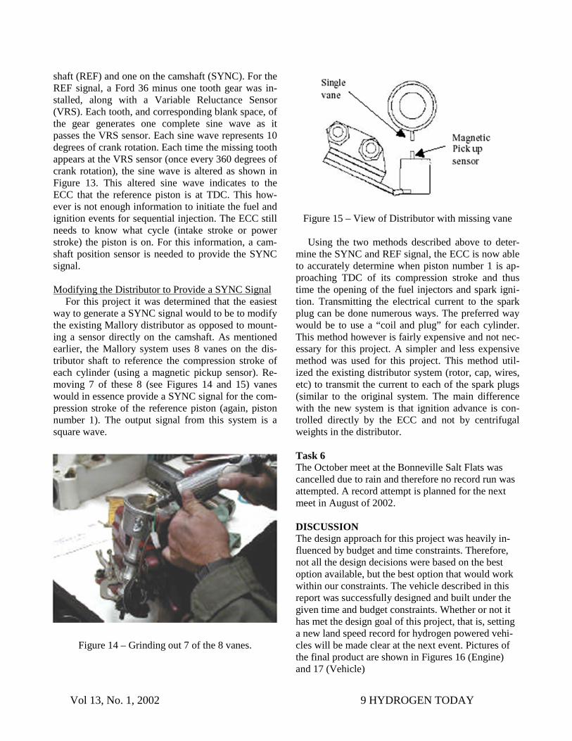
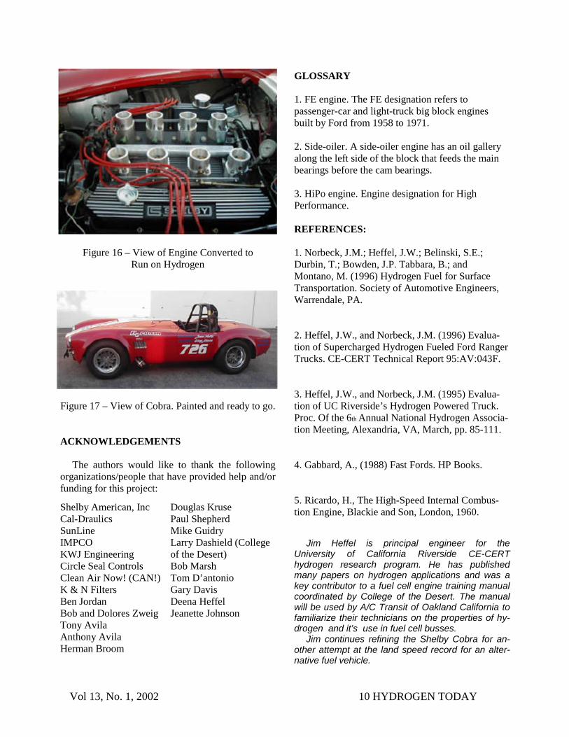
For this project it was determined that the easiest way to generate a SYNC signal would to be to modify the existing Mallory distributor as opposed to mount-ing a sensor directly on the camshaft. As mentioned earlier, the Mallory system uses 8 vanes on the dis-tributor shaft to reference the compression stroke of each cylinder (using a magnetic pickup sensor). Re-moving 7 of these 8 (see Figures 14 and 15) vanes would in essence provide a SYNC signal for the com-pression stroke of the reference piston (again, piston number 1). The output signal from this system is a square wave.
Figure 14 – Grinding out 7 of the 8 vanes.
Figure 15 – View of Distributor with missing vane
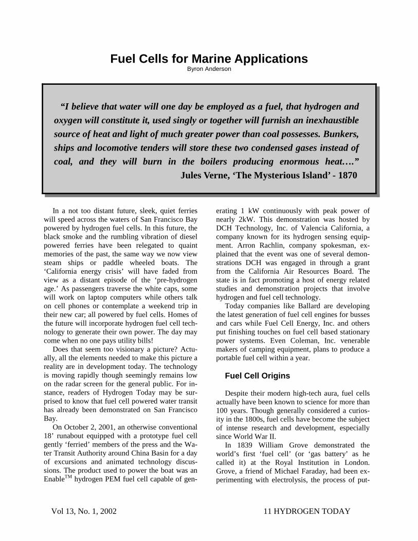
Using the two methods described above to deter-mine the SYNC and REF signal, the ECC is now able to accurately determine when piston number 1 is ap-proaching TDC of its compression stroke and thus time the opening of the fuel injectors and spark igni-tion. Transmitting the electrical current to the spark plug can be done numerous ways. The preferred way would be to use a “coil and plug” for each cylinder. This method however is fairly expensive and not nec-essary for this project. A simpler and less expensive method was used for this project. This method util-ized the existing distributor system (rotor, cap, wires, etc) to transmit the current to each of the spark plugs (similar to the original system. The main difference with the new system is that ignition advance is con-trolled directly by the ECC and not by centrifugal weights in the distributor. Task 6 The October meet at the Bonneville Salt Flats was cancelled due to rain and therefore no record run was attempted. A record attempt is planned for the next meet in August of 2002. DISCUSSION The design approach for this project was heavily in-fluenced by budget and time constraints. Therefore, not all the design decisions were based on the best option available, but the best option that would work within our constraints. The vehicle described in this report was successfully designed and built under the given time and budget constraints. Whether or not it has met the design goal of this project, that is, setting a new land speed record for hydrogen powered vehi-cles will be made clear at the next event. Pictures of the final product are shown in Figures 16 (Engine) and 17 (Vehicle)
Vol 13, No. 1, 2002 10 HYDROGEN TODAY
Figure 16 – View of Engine Converted to Run on Hydrogen
Figure 17 – View of Cobra. Painted and ready to go. ACKNOWLEDGEMENTS
The authors would like to thank the following organizations/people that have provided help and/or funding for this project:
GLOSSARY 1. FE engine. The FE designation refers to passenger-car and light-truck big block engines built by Ford from 1958 to 1971. 2. Side-oiler. A side-oiler engine has an oil gallery along the left side of the block that feeds the main bearings before the cam bearings. 3. HiPo engine. Engine designation for High Performance. REFERENCES: 1. Norbeck, J.M.; Heffel, J.W.; Belinski, S.E.; Durbin, T.; Bowden, J.P. Tabbara, B.; and Montano, M. (1996) Hydrogen Fuel for Surface Transportation. Society of Automotive Engineers, Warrendale, PA. 2. Heffel, J.W., and Norbeck, J.M. (1996) Evalua-tion of Supercharged Hydrogen Fueled Ford Ranger Trucks. CE-CERT Technical Report 95:AV:043F. 3. Heffel, J.W., and Norbeck, J.M. (1995) Evalua-tion of UC Riverside’s Hydrogen Powered Truck. Proc. Of the 6th Annual National Hydrogen Associa-tion Meeting, Alexandria, VA, March, pp. 85-111. 4. Gabbard, A., (1988) Fast Fords. HP Books. 5. Ricardo, H., The High-Speed Internal Combus-tion Engine, Blackie and Son, London, 1960. Shelby American, Inc
Cal-Draulics SunLine IMPCO KWJ Engineering Circle Seal Controls Clean Air Now! (CAN!) K & N Filters Ben Jordan Bob and Dolores Zweig Tony Avila Anthony Avila Herman Broom
Douglas Kruse Paul Shepherd Mike Guidry Larry Dashield (College of the Desert) Bob Marsh Tom D’antonio Gary Davis Deena Heffel Jeanette Johnson
Jim Heffel is principal engineer for the University of California Riverside CE-CERT hydrogen research program. He has published many papers on hydrogen applications and was a key contributor to a fuel cell engine training manual coordinated by College of the Desert. The manual will be used by A/C Transit of Oakland California to familiarize their technicians on the properties of hy-drogen and it’s use in fuel cell busses.
Jim continues refining the Shelby Cobra for an-other attempt at the land speed record for an alter-native fuel vehicle.
Vol 13, No. 1, 2002 11 HYDROGEN TODAY
In a not too distant future, sleek, quiet ferries will speed across the waters of San Francisco Bay powered by hydrogen fuel cells. In this future, the black smoke and the rumbling vibration of diesel powered ferries have been relegated to quaint memories of the past, the same way we now view steam ships or paddle wheeled boats. The ‘California energy crisis’ will have faded from view as a distant episode of the ‘pre-hydrogen age.’ As passengers traverse the white caps, some will work on laptop computers while others talk on cell phones or contemplate a weekend trip in their new car; all powered by fuel cells. Homes of the future will incorporate hydrogen fuel cell tech-nology to generate their own power. The day may come when no one pays utility bills!
Does that seem too visionary a picture? Actu-ally, all the elements needed to make this picture a reality are in development today. The technology is moving rapidly though seemingly remains low on the radar screen for the general public. For in-stance, readers of Hydrogen Today may be sur-prised to know that fuel cell powered water transit has already been demonstrated on San Francisco Bay.
On October 2, 2001, an otherwise conventional 18’ runabout equipped with a prototype fuel cell gently ‘ferried’ members of the press and the Wa-ter Transit Authority around China Basin for a day of excursions and animated technology discus-sions. The product used to power the boat was an EnableTM hydrogen PEM fuel cell capable of gen-
erating 1 kW continuously with peak power of nearly 2kW. This demonstration was hosted by DCH Technology, Inc. of Valencia California, a company known for its hydrogen sensing equip-ment. Arron Rachlin, company spokesman, ex-plained that the event was one of several demon-strations DCH was engaged in through a grant from the California Air Resources Board. The state is in fact promoting a host of energy related studies and demonstration projects that involve hydrogen and fuel cell technology.
Today companies like Ballard are developing the latest generation of fuel cell engines for busses and cars while Fuel Cell Energy, Inc. and others put finishing touches on fuel cell based stationary power systems. Even Coleman, Inc. venerable makers of camping equipment, plans to produce a portable fuel cell within a year.
Fuel Cell Origins Despite their modern high-tech aura, fuel cells
actually have been known to science for more than 100 years. Though generally considered a curios-ity in the 1800s, fuel cells have become the subject of intense research and development, especially since World War II.
In 1839 William Grove demonstrated the world’s first ‘fuel cell’ (or ‘gas battery’ as he called it) at the Royal Institution in London. Grove, a friend of Michael Faraday, had been ex-perimenting with electrolysis, the process of put-
“I believe that water will one day be employed as a fuel, that hydrogen and
oxygen will constitute it, used singly or together will furnish an inexhaustible source of heat and light of much greater power than coal possesses. Bunkers, ships and locomotive tenders will store these two condensed gases instead of coal, and they will burn in the boilers producing enormous heat….” Jules Verne, ‘The Mysterious Island’ - 1870
Fuel Cells for Marine Applications Byron Anderson
Vol 13, No. 1, 2002 12 HYDROGEN TODAY
ting an electrical current through a fluid, in this case sulfuric acid. What surprised him was that when he disconnected the apparatus it seemed to work back-wards and he observed that he was now generating a small voltage. Unfortunately the materials that Grove used were unstable and public interest dwin-dled. It wasn’t until the 1960’s that fuel cells were revived for use on manned space flights. NASA de-veloped fuel cells as the ideal supply of both power and drinking water.
Fuel Cells for the Uninitiated
For those not familiar with fuel cells are or why
they have become the ‘darling technology’ that may be the choice for our transportation-energy future, let’s briefly examine how they work; the benefits they will bestow and some of the technology hur-dles that must be overcome.
Everyone is familiar with batteries, every car has one. A car battery has several cells that store an electrical charge. Combined they deliver 12 volts of direct current (DC). The difference between a bat-tery and a fuel cell is that whereas batteries STORE electricity, a fuel cell GENERATES electricity. Electricity from a fuel cell is generated by the elec-tro-chemical reaction taking place between two gases, hydrogen and oxygen. The key to understand-ing the source of energy generated in a fuel cell is that the hydrogen - oxygen reaction can be ‘intercepted’ to capture small amounts of electricity. (electrons) The byproduct of this reaction is the for-mation of water (H2O).lll
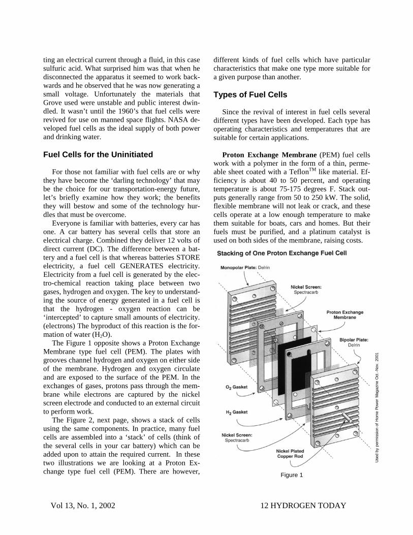
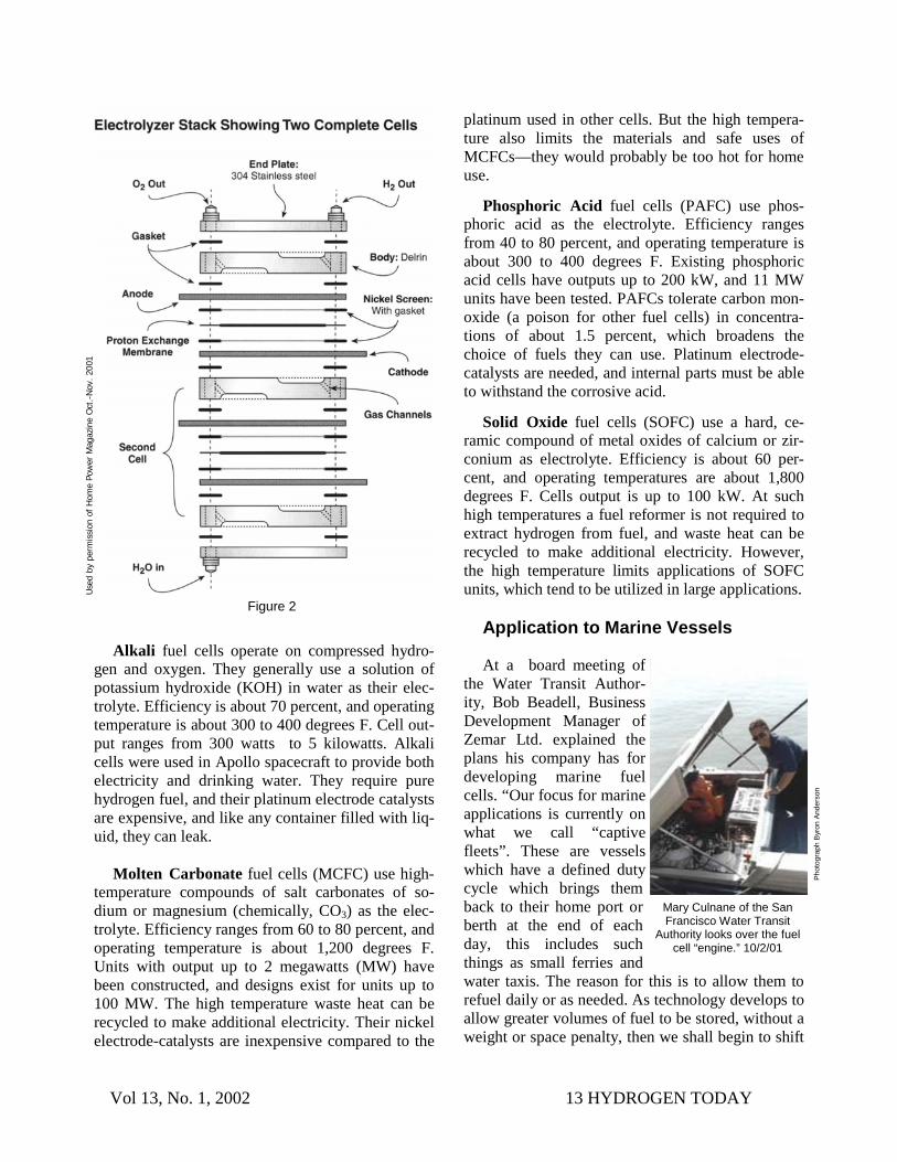
The Figure 1 opposite shows a Proton Exchange Membrane type fuel cell (PEM). The plates with grooves channel hydrogen and oxygen on either side of the membrane. Hydrogen and oxygen circulate and are exposed to the surface of the PEM. In the exchanges of gases, protons pass through the mem-brane while electrons are captured by the nickel screen electrode and conducted to an external circuit to perform work.
The Figure 2, next page, shows a stack of cells using the same components. In practice, many fuel cells are assembled into a ‘stack’ of cells (think of the several cells in your car battery) which can be added upon to attain the required current. In these two illustrations we are looking at a Proton Ex-change type fuel cell (PEM). There are however,
different kinds of fuel cells which have particular characteristics that make one type more suitable for a given purpose than another.
Types of Fuel Cells
Since the revival of interest in fuel cells several
different types have been developed. Each type has operating characteristics and temperatures that are suitable for certain applications.
Proton Exchange Membrane (PEM) fuel cells
work with a polymer in the form of a thin, perme-able sheet coated with a TeflonTM like material. Ef-ficiency is about 40 to 50 percent, and operating temperature is about 75-175 degrees F. Stack out-puts generally range from 50 to 250 kW. The solid, flexible membrane will not leak or crack, and these cells operate at a low enough temperature to make them suitable for boats, cars and homes. But their fuels must be purified, and a platinum catalyst is used on both sides of the membrane, raising costs.
Use
d by
per
mis
sion
of
Hom
e Po
wer
Mag
azin
e O
ct.-
Nov
. 200
1
Figure 1
Vol 13, No. 1, 2002 13 HYDROGEN TODAY
Alkali fuel cells operate on compressed hydro-gen and oxygen. They generally use a solution of potassium hydroxide (KOH) in water as their elec-trolyte. Efficiency is about 70 percent, and operating temperature is about 300 to 400 degrees F. Cell out-put ranges from 300 watts to 5 kilowatts. Alkali cells were used in Apollo spacecraft to provide both electricity and drinking water. They require pure hydrogen fuel, and their platinum electrode catalysts are expensive, and like any container filled with liq-uid, they can leak.
Molten Carbonate fuel cells (MCFC) use high-
temperature compounds of salt carbonates of so-dium or magnesium (chemically, CO3) as the elec-trolyte. Efficiency ranges from 60 to 80 percent, and operating temperature is about 1,200 degrees F. Units with output up to 2 megawatts (MW) have been constructed, and designs exist for units up to 100 MW. The high temperature waste heat can be recycled to make additional electricity. Their nickel electrode-catalysts are inexpensive compared to the
platinum used in other cells. But the high tempera-ture also limits the materials and safe uses of MCFCs—they would probably be too hot for home use.
Phosphoric Acid fuel cells (PAFC) use phos-phoric acid as the electrolyte. Efficiency ranges from 40 to 80 percent, and operating temperature is about 300 to 400 degrees F. Existing phosphoric acid cells have outputs up to 200 kW, and 11 MW units have been tested. PAFCs tolerate carbon mon-oxide (a poison for other fuel cells) in concentra-tions of about 1.5 percent, which broadens the choice of fuels they can use. Platinum electrode-catalysts are needed, and internal parts must be able to withstand the corrosive acid.
Solid Oxide fuel cells (SOFC) use a hard, ce-ramic compound of metal oxides of calcium or zir-conium as electrolyte. Efficiency is about 60 per-cent, and operating temperatures are about 1,800 degrees F. Cells output is up to 100 kW. At such high temperatures a fuel reformer is not required to extract hydrogen from fuel, and waste heat can be recycled to make additional electricity. However, the high temperature limits applications of SOFC units, which tend to be utilized in large applications.
Application to Marine Vessels At a board meeting of
the Water Transit Author-ity, Bob Beadell, Business Development Manager of Zemar Ltd. explained the plans his company has for developing marine fuel cells. “Our focus for marine applications is currently on what we call “captive fleets”. These are vessels which have a defined duty cycle which brings them back to their home port or berth at the end of each day, this includes such things as small ferries and water taxis. The reason for this is to allow them to refuel daily or as needed. As technology develops to allow greater volumes of fuel to be stored, without a weight or space penalty, then we shall begin to shift
Mary Culnane of the San Francisco Water Transit
Authority looks over the fuel cell “engine.” 10/2/01
Figure 2
Use
d by
per
mis
sion
of
Hom
e Po
wer
Mag
azin
e O
ct.-
Nov
. 200
1
Pho
togr
aph
Byro
n An
ders
on
Vol 13, No. 1, 2002 14 HYDROGEN TODAY
our focus to include offshore marine applications.” In speaking of the near term future of the tech-
nology Beadell said, “Most of these (fuel cells) are currently very expensive but all of the manufactur-ers expect costs to fall rapidly once they are mass produced….we expect even greater cost reductions due to the elimination of expensive catalysts and improvements in power density. This, taken into consideration with greatly reduced maintenance costs, will make Alkaline fuel cells very competitive with diesel or gas engines.” Zemar intends to return to the Bay Area early next year to demonstrate its alkaline fuel cell technology in a marine application.
Fuel Cell Benefits
One great appeal of fuel cells, as mentioned, is
that they generate electricity with no pollution and few if any moving parts. The hydrogen and oxygen used in generating electricity through this method ultimately combine to form water as a byproduct. Since fuel cells use hydrogen, one line of reasoning taken by economists and technologists envisions our whole economy based on hydrogen. This scenario, in which hydrogen is as renewable as rain, has been referred to as the “hydrogen economy.” A stable en-ergy cost is a must for economic productivity. A de-crease in the cost of energy will have a marked posi-tive effect on the economy just as every Californian know firsthand what the reverse brings.
Technology and Infrastructure Challenges
There are several technological hurdles that must
be overcome. Materials are expensive right now. Platinum is used in fuel cells as a catalyst but there are many promising materials under study that hold the promise of lower cost. Hydrogen storage has also been a historical problem because of low den-sity of the gas. The work being done with carbon nanotubes, metal hydrides, hydrogen bearing com-pounds (hydroxides), and higher pressure containers are all being examined. AHA president Roy McAl-ister has patents on a very promising storage tech-nology which is capable of storing hydrogen at greater than liquid densities.
Robert Hayden of the California Fuel Cell Part-nership in West Sacramento recently wrote, “The technological development of fuel cells as electric-ity generators for transportation and stationary sources is complex. Equally daunting is the matter of fueling. Where are we going to get the hydrogen needed to power fuel cells? How are we going to put the infrastructure in place that will make it as convenient and safe for consumers to get hydrogen as it is today to get gasoline and other fuels?”
From the standpoint of availability, the good news is that hydrogen is relatively easy to obtain from a number of sources and processes. Fossil fuel resellers need not fear because there are many R & D efforts underway to find the best ways to reform gasoline, natural gas, diesel and even coal.
The purest ideal though, is to derive hydrogen from renewable resources. The electrolysis of water powered by renewable energy such as solar or wind is the model most often mentioned. There is nothing to prevent such a plan from being put in place ex-cept the will to do so.
Fortunately the state of California is very inter-ested in encouraging the development of alternative energy including fuel cells. “Widespread use of fuel cells in water craft would certainly help California’s efforts to reduce air pollution,” said Dr. Alan Lloyd, Chairman of the California Air Resources Board in a recent press statement. In October 2001 the state department of energy announced a Request for Pro-posal (RFP) to study the whole issue of developing a hydrogen refueling infrastructure for fuel cell ve-
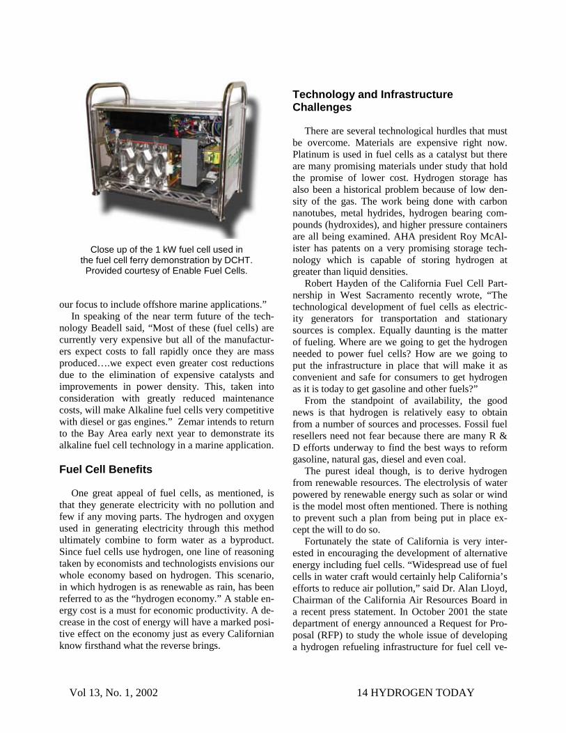
Close up of the 1 kW fuel cell used in the fuel cell ferry demonstration by DCHT. Provided courtesy of Enable Fuel Cells.

Vol 13, No. 1, 2002 15 HYDROGEN TODAY
Byron Anderson is an Advanced Transportation Technol-ogy Project Manager , fuel cell-electric vehicle instructor and contributing editor to Hydrogen Today.
Fuel Cell Ferry Update 4-10-02
The Water Transit Authority of San Francisco has recently announced it’s intention to fund the worlds first zero-emission commuter ferry ser-vice to run from Treasure Island to San Francisco. Through a Federal Grant the WTA has received $100,000 to develop the first com-mercial fuel cell ferry. By the end of this summer, the WTA plans to complete the final design of the small fuel cell ferry. The pro-posed fuel cell boat’s maximum speed would reach the compara-tively low speed of 12 knots, making it an ideal fit for the short distance between Treasure Island and San Francisco. The WTA plans to con-tribute $25,000 of its own State funds towards the project.
Read more about it at:
www.baycrossings.com—April 2002 issue.
Book Review Byron Anderson
Tomorrow’s Energy: Hydrogen, Fuel Cells,
and the Prospects for a Cleaner Planet Peter Hoffman
Peter Hoffman’s
book tells the rich his-tory of hydrogen tech-nology development over the past 100 years through the present. The book is quite compre-hensive in it’s review of all the positive efforts made to promote hydro-gen by individual scien-tists, engineers, inven-tors, environmentalists, governments, and cor-porations. Who were the supporters and what were their visions? The book includes some technical discussion of specific devices and processes, though nothing that most readers couldn’t understand. It is interesting to read how research has accelerated since the 1970’s, and thought provoking to overlay the influence of world events since then. Can we imagine how the events of the present will shape the hydrogen future?
I experienced some discomfort with references to using nuclear fission to produce hydrogen, a con-ceivable but arresting idea when first encountered. Since publication though, France has expressed great interest in using their nuclear power for ex-actly this purpose. Hoffman’s coverage was fairly balanced and authoritative. This is good reading for policy makers, students of hydrogen and anyone who wants to see the big picture. The use of hydro-gen as an alternative fuel has long suffered ma-ligned, uninformed viewpoints, or worse. Hoffman does a great service for us by closing many gaps in our knowledge of the historical perspective of hy-drogen.
1-5 Rating:
Peter Hoffman is editor of the Hydrogen & Fuel Cell Letter - http://www.hfcletter.com
hicles and vessels. The study will run two years and will be published in a series of reports. The recom-mendations of the final report may very well shape a future that matches Jules Verne's vision of the fu-ture.
Vol 13, No. 1, 2002 16 HYDROGEN TODAY
Have you ever wondered why some technolo-gies succeed and why others that seem brilliant, and innovative unexpectedly ‘flat line?’ What are the forces that act upon a technology causing one to integrate while another falls by the wayside? Upon reflection, our technological history seems littered with great inventions and ideas that never saw the light of day. Even today, many great ideas cling to existence in small pockets around the country, kept alive by a lone inventor or a group of local supporters and enthusiasts. Why doesn’t good technology succeed?
Conspiracy theories aside for the moment, there are five basic factors that can be identified which affect the development, implementation and ac-ceptance of any new technology. To better frame this premise, let’s look at the case of wind power following the oil embargo of 1973.
As a result of the 1973 oil embargo and later oil shocks, a nascent wind turbine industry began to develop in response to tremendous public interest in renewable energy. On the heels of public con-troversy came political support. The Federal Gov-ernment and impacted states like California began to focus hearings and panels on energy related problems. At the time, oil prices were high and everyone expected they would continue to rise for a decade or more, so a certain sense of urgency surrounded the whole debate. Unfortunately, there was a problem. In 1973, no good wind technology
existed in the U.S. In response, several companies like Westinghouse, United Technologies, Alcoa, Boeing and several smaller companies designed prototype wind turbines. Despite development, by 1978 it was clear that no turbines could withstand a serious wind for any length of time. Finally, apart from the $530 million spent for individual giant ma-chines that DOE put up (all of which failed), there was little capital available to build a wind energy industry, a result of the 1979-81 recession.
What kept the wind energy industry from blos-soming in the 1970’s was a lack of good technol-ogy, a lack of sustained capital funding, a fitful re-covery and stabilization of the oil market and the influx of the first wave of Japanese economy cars. Without any decisive technology and support, the wind movement had hit the doldrums.
What managed to keep wind power alive in the transition to the eighties were actions by the federal and state governments. The Federal Government offered tax incentives for individuals purchasing wind turbines and the State of California, provided an attractive program of tax credits. The latter had the affect of shifting nearly $2 billion in capital from the speculative real estate market in California, (“flat lined” during the recession), towards wind farm developments.
The sudden availability of these incentives at-tracted a more mature wind turbine technology from Denmark, which until then had been without a mar-ket. Within the 6-year life of the California tax credit program the worldwide wind energy industry went from a standing start to the fastest growing re-newable technology in the world and has continued to be the fastest growing every year since.
Out of this experience we can identify five fac-tors which played a role in the evolution of wind power. When these five factors synchronize, they create the best possible success scenario:
1. High Fossil Fuel Prices 2. High Level of Public Awareness 3. Political Will and Support 4. Viable Technology
In 1973 America experienced a great gaso-line and fuel oil shortage due to an embargo by OPEC nations. The prices for fuel sky-rocketed and the supply diminished. At the time the U.S. was importing around 30% of its oil from foreign sources. Today, we’ve come a long way. By 2002 our enlightened energy policies of the past decades have brought us to 60% dependency on foreign oil imports! For an instant replay of this note-worthy lesson in energy policy visit http://www.eia.doe.gov/emeu/plugs/pl25yrs.html
The Five Elements of Technology Transition Ty Cashman and Byron Anderson

Vol 13, No. 1, 2002 17 HYDROGEN TODAY
FACTS THAT EVERY CITIZEN SHOULD KNOW
ABOUT HYDROGEN
Lynette and Bill Thorp • Hydrogen is the only fuel which can, in both
production and use, contribute directly to elimi-nating many of our most insufferable environ-mental, economic, and health problems.
• Hydrogen is the only truly clean-burning, non-polluting fuel and can be used in virtually every application where other fuels are used today, with only water, heat, and negligible amounts of nitrogen compounds as by-products.
• Moreover hydrogen is the best medium for fuel cells, which produce electricity efficiently, qui-etly, and directly from fuel and oxygen (which may be from air), with only water and heat as the by-products.
• Hydrogen is the safest fuel; safer than gasoline, propane, natural gas, coal, or nuclear energy.
• Hydrogen can be easily stored and transported as a gas or liquid.
• On a pound-for-pound basis, hydrogen has more energy than any other fuel—about 3 times more than gasoline.
• Internal combustion engines (such as in cars, lawnmowers, etc.) powered by hydrogen, when properly adapted or designed specifically for hydrogen, operate more efficiently than with any other fuel. Most importantly, an internal combustion engine fueled with hydrogen actually cleans the air as it runs: the exhaust is cleaner than the input air.
• Hydrogen is colorless, odorless, tasteless, and non-toxic.
• Hydrogen is the simplest, lightest, and most abundant element in the universe.
• For all of the above reasons, hydrogen is the ideal energy medium.
• Proven technologies are available to make, store, transport, and use solar hydrogen: electrolysis of water, reforming hydrocarbons, bacterial digestion of biomass, and pyrolysis of biomass.
5. Incentives for Capital Investment
Our history lesson shows us how the course of growth in wind technology was deflected by tech-nology failures, current events, competing solutions, and policy enablers before finding a steady foot-hold. Imagine it being 1973 today. How difficult would it be to predict the set of circumstances which brought us to our current situation? Prognosticators predicted every kind of scenario for the adoption of renewables both optimistic and pessimistic, but none predicted what actually occurred.
Likewise, today as we consider the fate of hydro-gen technology in 2002 we find similar conflicting and competing forces shaping the future. The Cali-fornia Energy Crisis threatened, and did for a time, spill over to other states which alarmed Washington. Immediate action by FERC (plus a few phone calls to Texas, no doubt) averted further disasters. ‘9-11’ and world events continue to generate much debate about energy. One result has been significant an-nouncements by the government to fund fuel cell and hydrogen research. Today fuel cell technology is at the doorstep of commercialization. Yet political will has not entirely swung over to the direction of renewables and debate continues over where to get more oil. How this all will play out in the next few years is going to be fascinating. Will a hydrogen in-frastructure really take 30 years to roll out as pun-dits say? or will technology advances in storage and distribution render fueling infrastructure moot, pav-ing the way for a faster transition?
Many of our five factors are in strong evidence today. We have a portfolio of viable hydrogen tech-nologies, continued fossil fuel uncertainty and high cost, changes in political agendas and the formation of commercialization incentives.
Do we have sufficient public awareness of the technologies and the solutions they offer? This may be our “weakest link!” The general public is slowly beginning to appreciate the technology and the mag-nitude of promise it brings. As we have seen in the past, greater public awareness and demand is a key driver of policy change. “Let the people lead and the politicians will follow.” Do your part. Stay informed and write your local and state representatives to makeh them aware of your interests.
Ty Cashman, PhD., is President of Solar Economy Insti-tute in Mill Valley California.

Vol 13, No. 1, 2002 18 HYDROGEN TODAY
• On our planet, hydrogen is almost always combined with other elements. When combined only with oxygen, it is called water. When combined only with carbon, it is called a hydrocarbon. When combined only with carbon and oxygen, it is called a carbohydrate or an alcohol. The non-renewable fossil fuels (coal, natural gas, and petroleum and its derivitives) are hydrocarbons. Methane, the principle constituent of natural gas, is continuosly being produced by natual decay. Most carbohydrates are not edible and form the bulk of biomass: sewage, farm wastes (including manures), forestry wastes, garbage, and landfill trash.
• To make hydrogen available as a fuel, energy is required. For a renewable energy system, this energy must be derived directly from the sun (as heat or electricity), or indirectly (as electricity generated by wind or water).
• Hydrogen can be made from water by using the energy of the sun to create an electric current which can then be utilized to split (electrolyze) water into hydrogen and oxygen.
• Hydrogen can be produced from biomass (garbage, landfill accumulations, agricultural waste, paper products, feed lot waste and other wastes that contain hydrogen-bearing com-pounds.
• Existing automobile engines and other internal combustion engines could be economically con-verted to burn hydrogen fuel. The converted en-gines are then "minus zero emissions". The ex-haust is cleaner than the input air.
• The United States could make a significant tran-sition to hydrogen fuel by the year 2010.
• Solar hydrogen fuel can be produced to supply a clean sustainable supply of fuel for ALL human energy needs, FOREVER.
• A transition to a hydrogen energy system will be the most significant, ongoing, job-creating opportunity ever conceived for both blue and white collar workers.
• Hydrogen is the safest of all fuels. Gaseous hy-drogen is 14-times lighter than air, therefore it rapidly disperses into the atmosphere in the event of an accidental release. This is not true of other fuels. Other fuels have much greater "risk-time" until they are dispersed from the location of accidental release.
• No one was burned by the ignited hydrogen in the 1937 Hindenberg accident. Seven million cubic feet of hydrogen, equal in volume to a structure three football fields in size and 49 ft. in height, burned in less than one minute. How-ever, diesel fuel for the propulsion engines fell to the ground and continued to burn for many hours.
EFFICIENCY/ECONOMICS • If done to optimize economies of scale, many
methods of producing hydrogen would be cost competitive with fossils. or nuclear energy, when the life cycle method is used to derive the numbers.
• Imported oil costs the United States one billion dollars every 3 1/2 days.
• Using hydrogen in place of oil could reduce our annual trade deficit by 70 billion dollars. Even greater savings are available by eliminating the large military expenditures required to ensure delivery of foreign oil to the United States.
• The socially relevant costs of bringing a fuel to market must also include such factors as pollu-tion and other short and long-term environ-mental costs as well as direct and indirect health costs. When these factors are taken into consid-eration, together with its initial cost competi-tiveness, hydrogen is surely the most logical choice for a world wide energy medium.
• Strip mining of coal, that defaces and environ-mentally destroys huge areas, could be elimi-nated by using Solar Hydrogen.
• Forest lands, decimated for heating and cooking purposes by people in developing nations, can be preserved by utilizing hydrogen fuel.
• Many developing nations are endowed with abundant wind, water, or sun power that can be used to make hydrogen on a small scale for vil-lages and where appropriate, on a large scale.
• A substantial part of the expense in building and operating a fossil fuel or nuclear power plant is devoted to disposing wasted heat energy.
• Because fossil and nuclear plants must be lo-cated at some distance from where the electrical energy is used a conventional nuclear or fossil-fueled central power plant can deliver only
Vol 13, No. 1, 2002 19 HYDROGEN TODAY
about one-third of the energy of the fuel in the form of electricity. A hydrogen-fuel plant lo-cated near the customers can deliver 70% or more of the energy as a combination of "co-generated" heat and electricity in a pollution free system.
• Because hydrogen is pollution-free, small do-mestic or local power plants could be designed to utilize much of the energy we now throw away. Cogeneration with hydrogen could at least double energy utilization compared with present practices.
• These small power plants could be mass-produced so that the cost per kilowatt would be substantially less than that of large conventional power plants.
• Unlike electricity, whose production as a secon-dary energy medium must be juggled to accom-modate peak usage periods, hydrogen can be transported and stored for industrial and domes-tic need and to make electricity at virtually any time.
• Hydrogen could be cost competitive at 75 cents per gallon of gasoline. This estimate is based upon large-scale extraction from biomass wastes or solar thermal techniques utilizing large parabolic solar concentrator motor- gen-erators called Gensets. Solar Dish Gensets hold the world efficiency record for converting solar energy to electricity.
• Hydrogen packs more chemical energy in a pound for pound comparison than with any other fuel. Two pounds of hydrogen provides as much energy as a gallon of gasoline. About 2.2 gallons of water will supply enough hydrogen to replace one gallon of gasoline
• Introducing small amounts of hydrogen (2%-5%) into internal combustion engines, that are currently using fossil fuels like gasoline, diesel, or natural gas, increases the efficiency of com-bustion, improves mileage and reduces pollut-ants to a remarkable degree.
• Energy providers could reduce their costs of op-eration by a very substantial margin through elimination of most exploration, drilling, mill-ing, refining, and other cost intensive practices. These firms could reap enven larger profits than they do now by actively participating in the transition to hydrogen energy systems.
• MEV (minus emission vehicle) engines using hydrogen will last longer and start faster in any weather.
• The lubricating oil in an MEV engine will re-main clean for extended periods of time. There are no sulfur carbon compounds to degrade the oil.
• Hydrogen could become a lucrative cash crop for farmers in areas where there is abundant wind and/or solar radiation. Many farmers could profit financially by converting animal wastes and other biomass into hydrogen through a process of bio-remediation (using micro-organisms to break down unwanted or excess materials).
• It is less expensive to move hydrogen across the continent as a compressed gas by pipeline than an equal amount of electrical energy which re-quires power lines. Liquid hydrogen is the safest and most economical choice for moving energy across the oceans.
• Did you know that any of the following states could eventually be richer than Saudi Arabia by making and selling Solar-hydrogen? California, Arizona, Nevada, Oregon, Utah, Idaho, New Mexico, Colorado, Nebraska, Wyoming, Mon-tana, North Dakota, or Texas could provide end-less supplies of Solar-Hydrogen for the U.S. and other countries.
• Solar-Hydrogen could make the United States fuel-independent and pollution-free for as far into the future as the sun will shine.
• Implementation of a worldwide solar hydrogen energy system and carbon materials system could be tantamount to a Second, CLEAN In-dustrial Revolution or the Renewable Resources Revolution.
PRODUCTION • Solar energy is the most abundant available
source of energy on earth. Solar energy reaches the Earth at a rate that is 18,000 times the en-ergy consumed by human activities and is an ideal source for separating hydrogen from other elements.
• Wind power, tides and hydro-electric turbines (Dams) can also create electricity to split water

Vol 13, No. 1, 2002 20 HYDROGEN TODAY
into hydrogen and oxygen. When hydrogen is produced from the sun or other renewable en-ergy sources it is called "Solar-Hydrogen".
• Using a small portion of our total land area, we can manufacture enough Solar-Hydrogen to supply the entire energy requirement of the United States with Solar Gensets.
CARBON • Carbon is a valuable by-product of separating
hydrogen from carbon bearing compounds. Over $5.00 worth of carbon products can be ex-tracted from a gallon of gasoline, for example. The hydrogen left over could be used as fuel for cars which would clean the air of pollution caused by those vehicles using hydrocarbon fu-els: in the process of burning, pollution, carbon monoxide, and hydrocarbons are transformed into carbon dioxide and water.
• Carbon is the most versatile of all elements. With it we can make materials that are stronger than steel and do not rust. These materials can replace wood and steel in most structural appli-cations, for example cars, planes, homes, sky-scrapers, industrial plants, etc.
• About 74% of our landfills are carbon-bearing materials which can be converted into non-polluting hydrogen fuel and superior building materials.
• It is not rational to burn our petrocarbons (worth $100 a barrel) and deny future generations their right to these valuable resources. Fossil hydro-carbon reserves could be used to create a better economy by using them to produce durable goods (worth $3500 a barrel) such as plastics, synthetic fabrics, lubricants, solvents, carbon-fiber products that are stronger than steel, and countless other new products that are even now being developed.
APPLICATIONS • Hydrogen is now used to produce countless
products and to enhance many industrial proc-esses, for example pharmaceuticals, semi-conductors, margarine and other hydrogenated oil products, ammonia, gasoline, etc.
• The United Sates produces 100 billion cubic feet per year of hydrogen for industry and for the space program.
• The largest commercial user of hydrogen is the petroleum industry for converting crude oil into gasoline and hundreds of chemicals.
• Hydrogen is the best way to power fuel cell electric automobiles or existing vehicles that have internal combustion engines.
• Hydrogen fuel cells utilize the energy of a reac-tion between hydrogen and oxygen directly, quietly, and continuously produce electrical en-ergy for electric vehicle propulsion and any other use of electrical energy.
• Another advantage of fuel cells is that the de-vice also produces clean, potable water which is currently used on manned spacecraft and could also be useful for solving critical drinking water problems wherever potable water shortages ex-ist.
• One pound of hydrogen when combined with oxygen will make nine pounds of water. There-fore a hydrogen power plant could make valu-able quantities of high quality water to produce electricity.
• A Solar-Hydrogen powered heat pump could cool your house in summer and heat it in winter.
TRANSPORTATION, STORAGE, AND CONSUMER ACCESS • Hydrogen can be stored at room temperatures as
a hydride (hydrogen chemically combined with a metalic element) under little or no pressure and in a volume that is less than if it were a su-per-cold liquid
• Beginning in the early 1800's and into the 1950's, over 400 cities used hydrogen (mixed with other gases) for illumination, cooking, and heating. When pipelines were established for delivering natural gas from oil and gas fields, the gas mixtures were discontinued because natural gas was cheaper since it came from the ground as a pressurized gas that required little or no preparation for market.
• Hydrogen storage and distribution could be ac-complished with the same system of pipelines and liquid carriers now used for natural gas.

Vol 13, No. 1, 2002 21 HYDROGEN TODAY
• Depleted natural gas fields and similar geologi-cal formations could also be utilized for storing hydrogen.
• For those who prefer not to use batteries to store Solar-Electric energy, hydrogen could be pro-duced by electrolyzing water and the hydrogen could be stored in a tank and used as fuel when-ever needed.
• Hydrogen produced by bioremediation in China is chemically and physically the same as hydro-gen produced by wind power on a Nebraska farm. Hydrogen can therefore be used as a uni-versal medium of energy exchange.
• It is less expensive to move hydrogen across the continent as a compressed gas by pipeline than an equal amount of electrical energy which re-quires power lines. Pipelines are not as suscepti-ble to weather effects, such as high winds, ice storms, and heavy snow, as are electrical power lines.
• Liquid hydrogen is the safest and most eco-nomical choice for moving energy across the oceans.
ENVIRONMENT/ HEALTH • The Great Law of the Iroquois Nation says "In
our every deliberation, we must consider the im-pact of our decisions on the next seven genera-tions."
• All fuels need air (oxygen) for combustion. Hy-drogen is the only common fuel that is not chemically bound to carbon; therefore, when hydrogen burns in air it produces only heat en-ergy, water, and possibly trace amounts of ox-ides of nitrogen. Water and oxides of nitrogen are natural in our atmosphere.
• The burning of carbon-containing fuels (coal, oil, natural gas, propane, wood) burn, may cre-ate serious pollutants like carbon monoxide (a poisonous gas which is produced by incomplete combustion of carbon), carbon dioxide (a green-house gas), and an extensive list of complex hy-drocarbon chemicals and quantities of particu-late matter.
• Burning hydrogen does not contribute to the Greenhouse Effect, ozone depletion or acid rain. Transition to a hydrogen energy system could
restore the atmosphere to natural conditions pre-vailing before these anomalies became serious problems.
• Vast quantities of hydrocarbon seepage from tank farms, pipelines and 200,000 gasoline ser-vice station tanks now pollute our soil and aqui-fers. This pollution would be virtually elimi-nated by transition to hydrogen fuel.
• If liquid hydrogen is spilled it will very rapidly evaporate to gaseous hydrogen, leaving no pol-lution or toxic residue.x
• Pollutants from reliance on finite fossil fuels and nuclear energy are ultimately carried by the atmosphere and river systems to the oceans where they affect phytoplankton (that produce 80% of the earth's oxygen), flora and fauna of all kinds, particularly those marine species that comprise the ocean fisheries upon which all populations rely for a basic food source.
• Burning any fossil fuel creates pollutants (carbon monoxide, oxides of nitrogen, carbon particulates, raw fuel vapors and droplets) that cause millions of people to suffer from lung, respiratory, and allergic types of illness. Burn-ing hydrogen will eliminate much suffering and productivity losses and would substantially re-duce health care costs.
• Forest lands, decimated for heating and cooking purposes by people in developing nations, can be preserved by utilizing hydrogen fuel.
• To improve air quality some states have set zero emission standards for cars. A vehicle converted to operate on hydrogen easily meets this stan-dard and can actually improve upon it by clean-ing the air through which it travels by reducing atmospheric concentrations of carbon monox-ide, diesel soot, tire particles and unburned hy-drocarbons and converting these pollutants into carbon dioxide and water. This air cleaning ca-pability provides a Minus Emissions Vehicle (MEV). If the hydrogen has been derived frm renewable sources, it is called a Renewable En-ergy Vehicle - Minus Emissions, or REV-ME.
SECURITY • Development of hydrogen energy systems
would protect us from a possible national secu-
Vol 13, No. 1, 2002 22 HYDROGEN TODAY
rity disaster precipitated by a geopolitical up-heaval beyond our control.
• The use of hydrogen as the primary fuel would eliminate the impending crisis of the depletion of fossil fuels. The estimated petroleum reserves in the earth's crust are about one trillion barrels. Oil consumption is at 25 billion barrels per year and increasing at a rate of 1-1 1/2% per year. At current rates of consumption, measured against known reserves, there is only a 30 year supply of oil in the Earth's crust.
• The March 1998 "Scientific American" maga-zine, says in 10 years, the world will not be able to produce enough oil to meet the demand.
• Our current energy system is seriously inade-quate in terms of its ability to meet increasing demands into the future.
• In many ways Germany, Canada and Japan are ahead of the United States in research and de-velopment of hydrogen fuel and its applications. Mercedes and BMW have experimental hydro-gen-powered automobiles. Japanese automakers are testing hydrogen-powered cars. The United States lags behind.
• The USA reliance on imported petroleum is
about 60% our consumption, which is near twice the proporon it was during the 1970's gas crisis which threatened the stability our econ-omy. If there is another energy crisis, would we be willing to risk military action to secure our petroleum supply after our 60 day reserve is ex-hausted?
CONCLUSION
Is humanity ready to solve the problems created by world-wide resource depletion and pollution? A world-wide paradigm shift towards renewable en-ergy in general and Solar-Hydrogen in particular would bring the result of abundant renewable fuel, off grid electricity, cheaper heating and cooling, re-newed entrepreneurial and industrial opportunities, a stronger economy and a pollution-free world with healthier people.
Air Cleaning Engine (ACE) Projects
by Deek Harrison
In February 2000, Lou Linxwiler and Deek Har-
rison were discussing the need for a "Proof" car to demonstrate how Hydrogen powered internal com-bustion engines can actually clean carbon monoxide, pollen, diesel soot and other SMOG-producing hy-drocarbons from the AMBIENT air. That should be a startling hope to anyone that you are educating about Hydrogen as a fuel.
Lou suggested we build a "rolling chassis" dis-play for the April "Association of Handmade Autos" show at Knotts Berry Farm. See www.precisiondesign.com for Lou’s firm that makes cars like the red ones used in the movie "Ferris Buel-hler’s Day Off". No, they weren’t destroying Ferra-ris, those were Kit cars. We selected a Mustang 5.0HO crate engine, as well as the previous year’s Mfr. Trophy chassis design from Lou, and forged ahead. Phoenix’s Rotary 100 club joined AHA members in the initial fund drive and we raised enough of the estimated budget to make a good start.
Deek found a group of good but used CNG tanks, and as soon as we could get the chassis, Larry Malli-nak and his son Chris began welding mounts for one of the 142-lb. tanks. By using 1/8" co-polymer rub-ber pads with extra toughness instead of ¼" we were just able to fit it in the space available. Deek had also scrounged up enough usable high-pressure stainless tubing to plumb the car. But the Swagelok fittings came to almost $700. But the tubing and fit-tings give us a 10,000-psi plumbing system!
To maintain the original engine as stock as possi-ble for its new life with hydrogen we removed the butterfly valve from the air intake and substituted a K-N Filter. This would give us an un-throttled op-eration with SparkInjectors providing injection of hydrogen after closure of the combustion chambers and ignition close to TDC. Roy McAlister worked day and night and came up with 8 SparkInjectors in time for the Knotts Berry trip. Larry Malinak and Chuck Terrey fabricated a gorgeous Hydrogen fuel manifold and we were off to a successful show at Knotts Berry Farm.
Kit car builders were really interested in the car
Vol 13, No. 1, 2002 23 HYDROGEN TODAY
and so were many others. On the way back we stopped at Quartsite, Arizona, and were found by Kyle Petty’s racing team which was escorting 40 Bikers on a charity ride across the US. The driver asked what we had on the trailer and immediately ran to get Petty’s Chief Mechanic who had been try-ing to build a Hydrogen powered racer for over two years. He studied the SparkInjectors and yelled "that’s the solution I’ve been looking for." Unfortu-nately, Kyle’s son was killed the next week and the contact has not been re-established.
Then came the computer-timing program! Mo-torola felt they could re-program it for our direct in-jection and ignition-timing change needs in about 20 minutes if Ford would give them permission to re-member what they know. Permission was not given and Ford has not offered to reprogram the engine computer. If anyone knows how to reprogram the Ford/Motorola engine computer or if you simply want to contribute to the ACE project contact AHA.
TESY The Total Energy System That Doubles
Energy Utilization Efficiency
Chuck Terrey and Roy McAlister
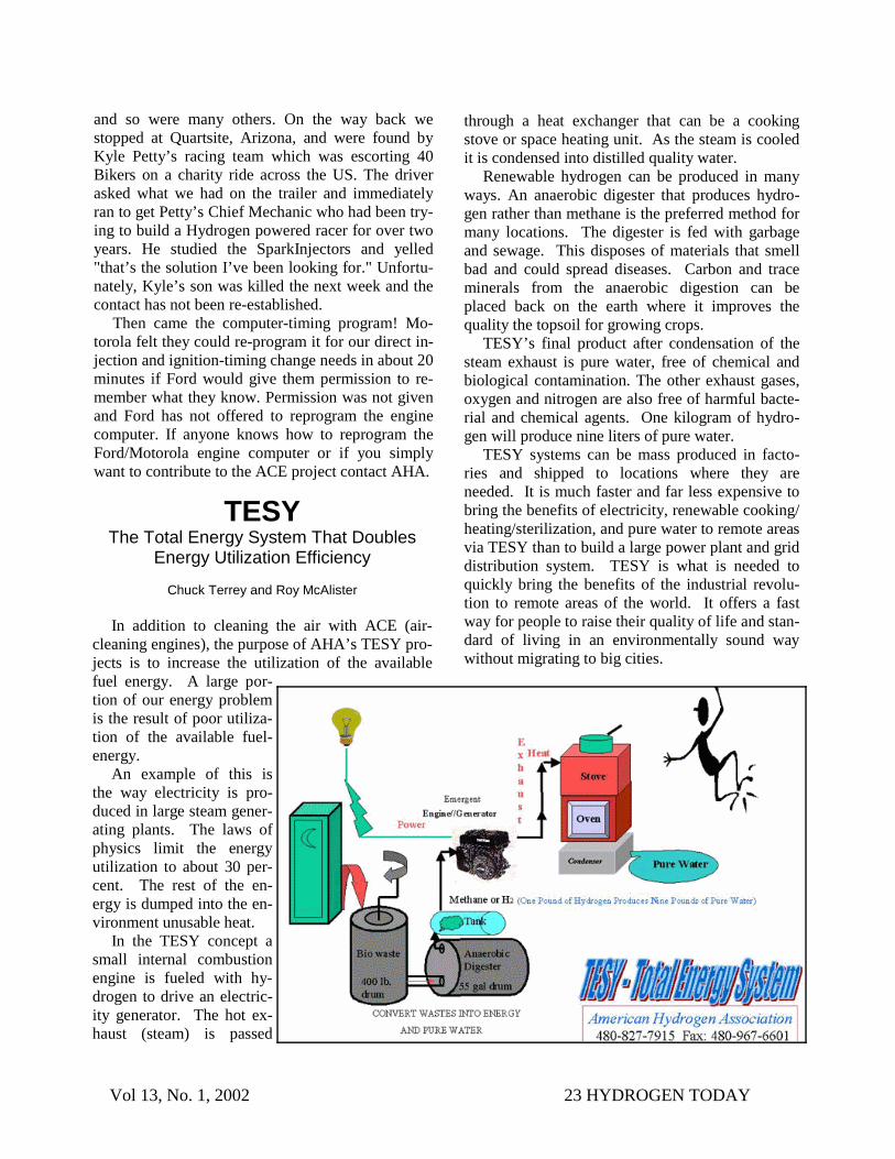
In addition to cleaning the air with ACE (air-cleaning engines), the purpose of AHA’s TESY pro-jects is to increase the utilization of the available fuel energy. A large por-tion of our energy problem is the result of poor utiliza-tion of the available fuel-energy.
An example of this is the way electricity is pro-duced in large steam gener-ating plants. The laws of physics limit the energy utilization to about 30 per-cent. The rest of the en-ergy is dumped into the en-vironment unusable heat.
In the TESY concept a small internal combustion engine is fueled with hy-drogen to drive an electric-ity generator. The hot ex-haust (steam) is passed
through a heat exchanger that can be a cooking stove or space heating unit. As the steam is cooled it is condensed into distilled quality water.
Renewable hydrogen can be produced in many ways. An anaerobic digester that produces hydro-gen rather than methane is the preferred method for many locations. The digester is fed with garbage and sewage. This disposes of materials that smell bad and could spread diseases. Carbon and trace minerals from the anaerobic digestion can be placed back on the earth where it improves the quality the topsoil for growing crops.
TESY’s final product after condensation of the steam exhaust is pure water, free of chemical and biological contamination. The other exhaust gases, oxygen and nitrogen are also free of harmful bacte-rial and chemical agents. One kilogram of hydro-gen will produce nine liters of pure water.
TESY systems can be mass produced in facto-ries and shipped to locations where they are needed. It is much faster and far less expensive to bring the benefits of electricity, renewable cooking/heating/sterilization, and pure water to remote areas via TESY than to build a large power plant and grid distribution system. TESY is what is needed to quickly bring the benefits of the industrial revolu-tion to remote areas of the world. It offers a fast way for people to raise their quality of life and stan-dard of living in an environmentally sound way without migrating to big cities.
Vol 13, No. 1, 2002 24 HYDROGEN TODAY
REQUEST FORM “The problem is clear, the air isn’t...”
a quote from the Pollution-Free Planet Committee Yes, I want to join AHA, or give a gift to help make a transition to clean Hydrogen energy. Yes, Enroll me in the automotive conversion class on October 7 & 8th, 2002. Yes, Enroll me in the fuel cell short course on October 14 and 15th, 2002. Name ____________________________________________________________________ Address ___________________________________________________________________ City ________________________________ State____________ Zip ________________ Telephone-Home(_____) ________-_________ Office(_____) ________-______________
Regular membership ($39/year) Family membership ($49/year) Senior/student membership ($25/year) Sustaining membership ($100/year) Corporation/Institutional ($2,500/year) Auto conversion & Fuel
Cell Class deposit ($50.) For foreign mailing, please add US$8.00 Other donation. Consider a life income gift. Make a tax advantaged gift to AHA while retaining income on
the capital for life. Donations to the American Hydrogen Association are Tax Deductible to the extent allowed under IRS 501(c) 3 for a non-profit Organization. Enclose Check or Money Order and Mail to:
American Hydrogen Association 1739 W. 7th Ave, Mesa, AZ 85202-1906 Phone: (480) 827-7915 or Fax: (480) 967-6601
Visit our website: www.clean-air.org e-mail us at: [email protected]
THE HYDROGEN ASSOCIATION 1739 W. 7th Avenue Mesa, AZ 85202-1906 USA
NON-PROFIT ORGANIZATION
U.S. Postage PAID
Phoenix, AZ Permit No. 2295