Embed Size (px)
Citation preview

EE 597: Wireless Networks (Spring 12)
Intro to Cellular and WiFi Networks
Bhaskar Krishnamachari=
University of Southern CaliforniaAutonomous Networks Research Group
No. 2
These slides were prepared by Dr. Kyuho Son, [email protected], visitingscholar at USC.
Acknowledgement

University of Southern CaliforniaAutonomous Networks Research Group
No. 3
1G 2G 3G 4G
AnalogAMPS
Digital / PCSGSM, CDMA (IS-95)
WCDMACDMA2000
OFDM& MIMO
History of Cellular Technology
University of Southern CaliforniaAutonomous Networks Research Group
No. 4
1G
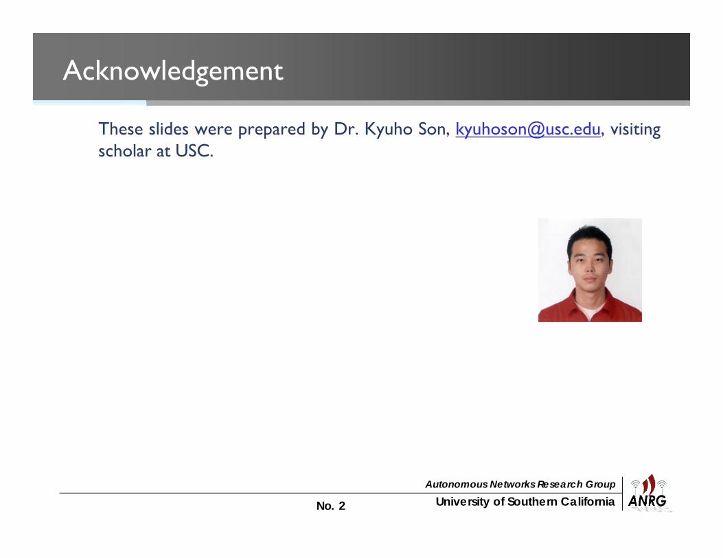
• First generation cellular systems– Analog cellphone standards– Introduced in the 80’s and continued until being replaced by 2G digital
cellphone standards– Used FDMA with 30kHz FM-modulated voice channels
• 1G standards– AMPS (Advanced Mobile Phone System) in the United States– NMT (Nordic Mobile Telephone) in Nordic countries, Eastern Europe
and Russia
• Speed– Average between 4,800 to 9,600 bps (bits per second)

University of Southern CaliforniaAutonomous Networks Research Group
No. 5
2G
• Second generation cellular systems– Digital cellphone standards– Mainly for digital voice, but SMS (short message service) is also available
• Two types of 2G standards– TDMA-based
• GSM (Global System for Mobile Communication) originally from Europe butused worldwide
• IS-136 aka D-AMPS (simply referred as TDMA) in the US
– CDMA-based• IS-95 aka cdmaOne (simply referred as CDMA) in the US and parts of Asia• PDC (Personal Digital Cellular) used exclusively in Japan
• Speed– Up to 144 Kbps (2.5G in EDGE)

University of Southern CaliforniaAutonomous Networks Research Group
No. 6
Types of Multiple Access
• Multiple access– The way of combining multiple data streams into one signal over a
shared medium
Frequency Division Multiple Access (FDMA)
Time Division Multiple Access (TDMA)
Code Division Multiple Access (CDMA)
Source: A. Goldsmith, Wireless Communications

University of Southern CaliforniaAutonomous Networks Research Group
No. 7
3G
• Third generation cellular systems– Provide the ability to transfer both voice and data (such as downloading
information, exchanging email, and instant messaging)– Broadband (5MHz)– Global roaming
• 3G standards– CDMA2000– WCDMA (Wideband CDMA)– TD-SCDNA (Time Division Synchronous CDMA)
• Speed– 384Kbps (moving) & 2Mbps (stationary)
University of Southern CaliforniaAutonomous Networks Research Group
No. 8
4G
• Fourth generation cellular systems– Data-focused standards
• Speed– Much higher data rates (50-100 Mbps)
• Key technologies for high spectral efficiency in 4G– OFDM (Orthogonal Frequency-Division Multiplexing) / OFDMA– MIMO (Multiple-Input and Multiple-Output)
• Two competing standards:– 3GPP LTE (Long Term Evolution)– WiMax (Worldwide Interoperability for Microwave Access)

University of Southern CaliforniaAutonomous Networks Research Group
No. 9
Network Architecture

University of Southern CaliforniaAutonomous Networks Research Group
No. 10
Cellular Concept
• Early mobile radio system– Similar to television broadcasting
– One very powerful transmitter located at a tall tower• Large area coverage but difficult to spatially reuse the same frequencies
throughout the system due to significant interference• In 1970, Bell had a mobile system in NYC with a single high power
transmitter, it could only support 12 simultaneous calls. (limited capacity!)
University of Southern CaliforniaAutonomous Networks Research Group
No. 11
Cellular Concept
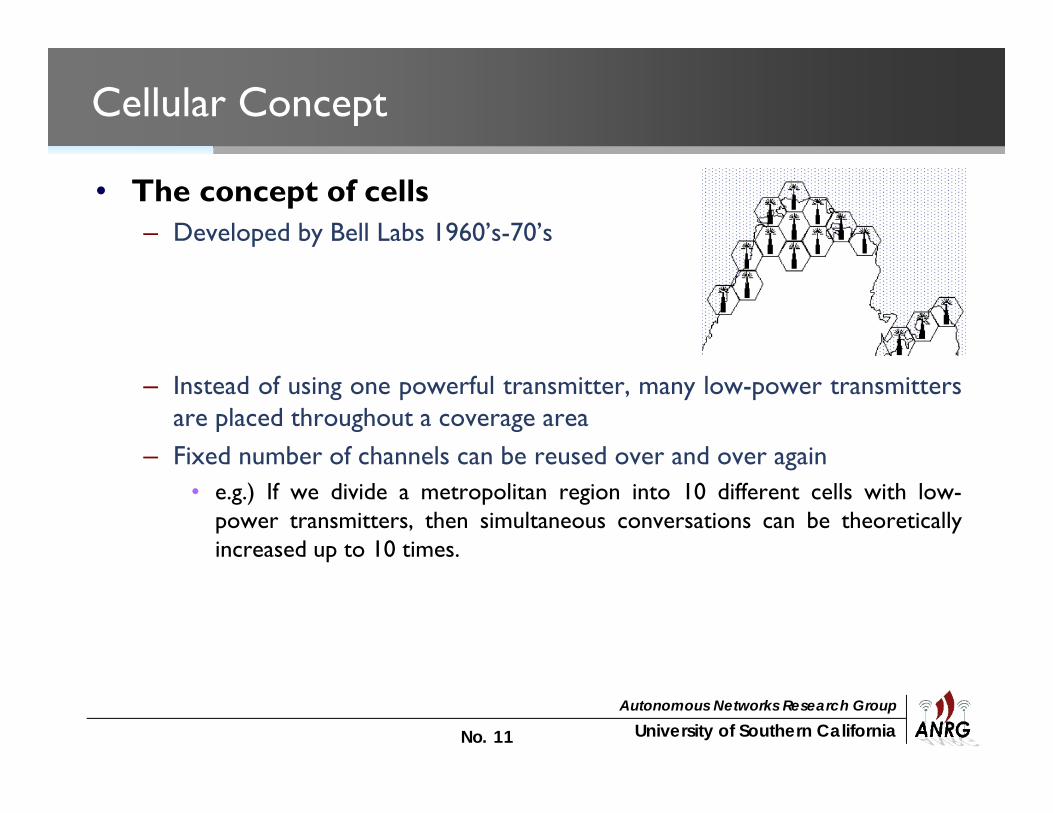
• The concept of cells– Developed by Bell Labs 1960’s-70’s
– Instead of using one powerful transmitter, many low-power transmittersare placed throughout a coverage area
– Fixed number of channels can be reused over and over again• e.g.) If we divide a metropolitan region into 10 different cells with low-
power transmitters, then simultaneous conversations can be theoreticallyincreased up to 10 times.

University of Southern CaliforniaAutonomous Networks Research Group
No. 12
Frequency Reuse
•
Reuse-3 system (i=j=1) Reuse-7 system (i=2, j=1)
University of Southern CaliforniaAutonomous Networks Research Group
No. 13
Frequency Reuse
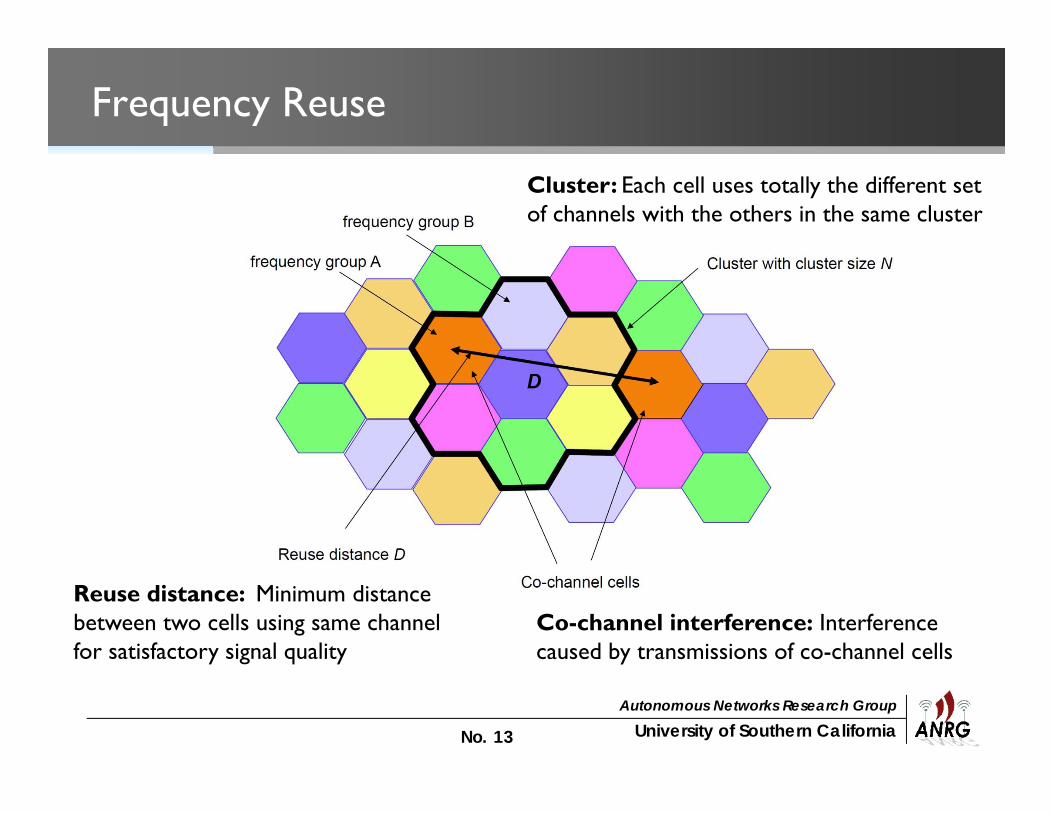
Co-channel interference: Interference caused by transmissions of co-channel cells
Reuse distance: Minimum distance between two cells using same channel for satisfactory signal quality
Cluster: Each cell uses totally the different set of channels with the others in the same cluster

University of Southern CaliforniaAutonomous Networks Research Group
No. 14
Increasing Spectral Efficiency
• Demands for service keeps increasing• Techniques to improve the capacity of cellular systems
– Cell splitting– Sectorization– Fractional frequency reuse

University of Southern CaliforniaAutonomous Networks Research Group
No. 15
Cell Splitting
• Cell splitting– Subdividing a congested cell into smaller cells (reducing cell radius and
keeping the D/R ratio unchanged) with a corresponding reduction intransmit power and antenna height
– Can increase capacity by increasing the number of BSs
Macro cell (low density)
Micro cell (high density)
Pico cell (higher density)
University of Southern CaliforniaAutonomous Networks Research Group
No. 16
Sectorization
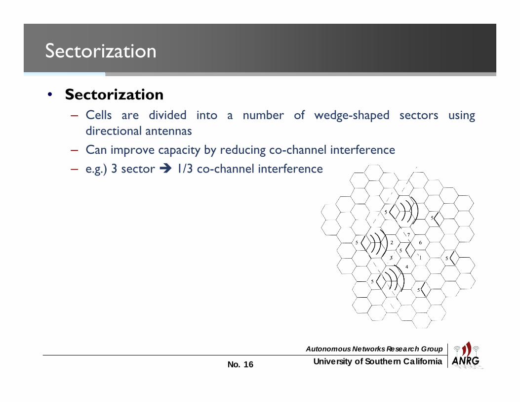
• Sectorization– Cells are divided into a number of wedge-shaped sectors using
directional antennas– Can improve capacity by reducing co-channel interference– e.g.) 3 sector 1/3 co-channel interference
University of Southern CaliforniaAutonomous Networks Research Group
No. 17
Fractional Frequency Reuse
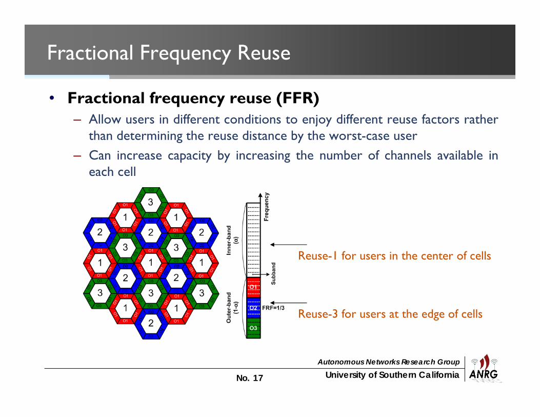
• Fractional frequency reuse (FFR)– Allow users in different conditions to enjoy different reuse factors rather
than determining the reuse distance by the worst-case user– Can increase capacity by increasing the number of channels available in
each cell
Reuse-1 for users in the center of cells
Reuse-3 for users at the edge of cells

University of Southern CaliforniaAutonomous Networks Research Group
No. 18
Handoff (or Handover)
• Reason for handoff– Moving out of coverage– Load balancing
• Handoff decision– Relative signal strength (S1 < S2)– Threshold (S1 < threshold)– Hysteresis and dwell time to avoid ping-pong effects

University of Southern CaliforniaAutonomous Networks Research Group
No. 19
Handoff
• Hard handoff– If adjacent cells do not have the same frequency, then channel and BS
must change.– Break-before-make
• Soft handoff– In IS-95 CDMA, all cells use the same channel.– Only serving BS needs to be changed.– Make-before-break– Rake receiver

IEEE 802.11 Wireless LAN Overview

University of Southern CaliforniaAutonomous Networks Research Group
No. 21
Overview – 802.11 Wireless LAN (WLAN)
• Wireless Ethernet with compatible speed• Supports up to 11 and/or 54 Mbps within >100 m range• Operates at unlicensed ISM (Industrial, Scientific and
Medical) bands at 2.4GHz (802.11 b/g) / 5GHz (802.11 a)• Common MAC supports multiple PHYs (DSSS / FHSS /
Infrared / OFDM)

University of Southern CaliforniaAutonomous Networks Research Group
No. 22
Two Configuration Modes 1/2
• 1. Infrastructure mode– Infrastructure Basic Service Set (BSS)– An access point (AP) and multiple stations (STAs)– Every transmission is with AP– No peer-to-peer communication
Wired Internet
University of Southern CaliforniaAutonomous Networks Research Group
No. 23
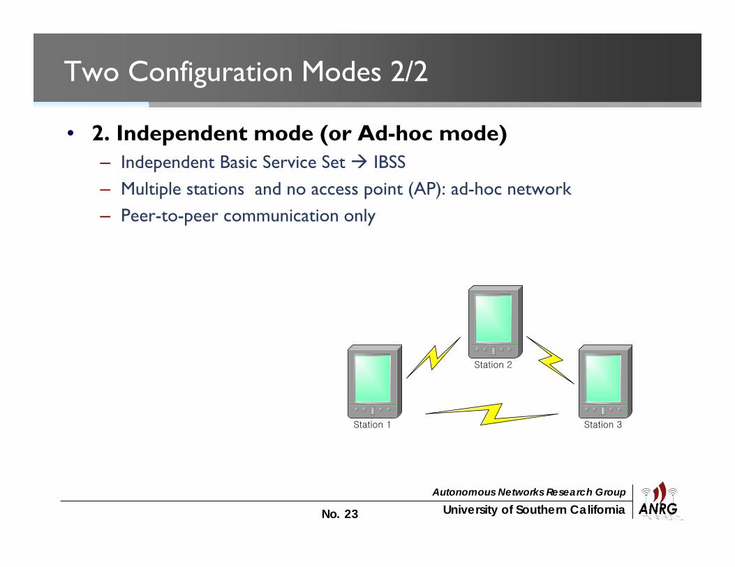
Two Configuration Modes 2/2
• 2. Independent mode (or Ad-hoc mode)– Independent Basic Service Set IBSS– Multiple stations and no access point (AP): ad-hoc network– Peer-to-peer communication only
Station 3Station 1
Station 2
University of Southern CaliforniaAutonomous Networks Research Group
No. 24
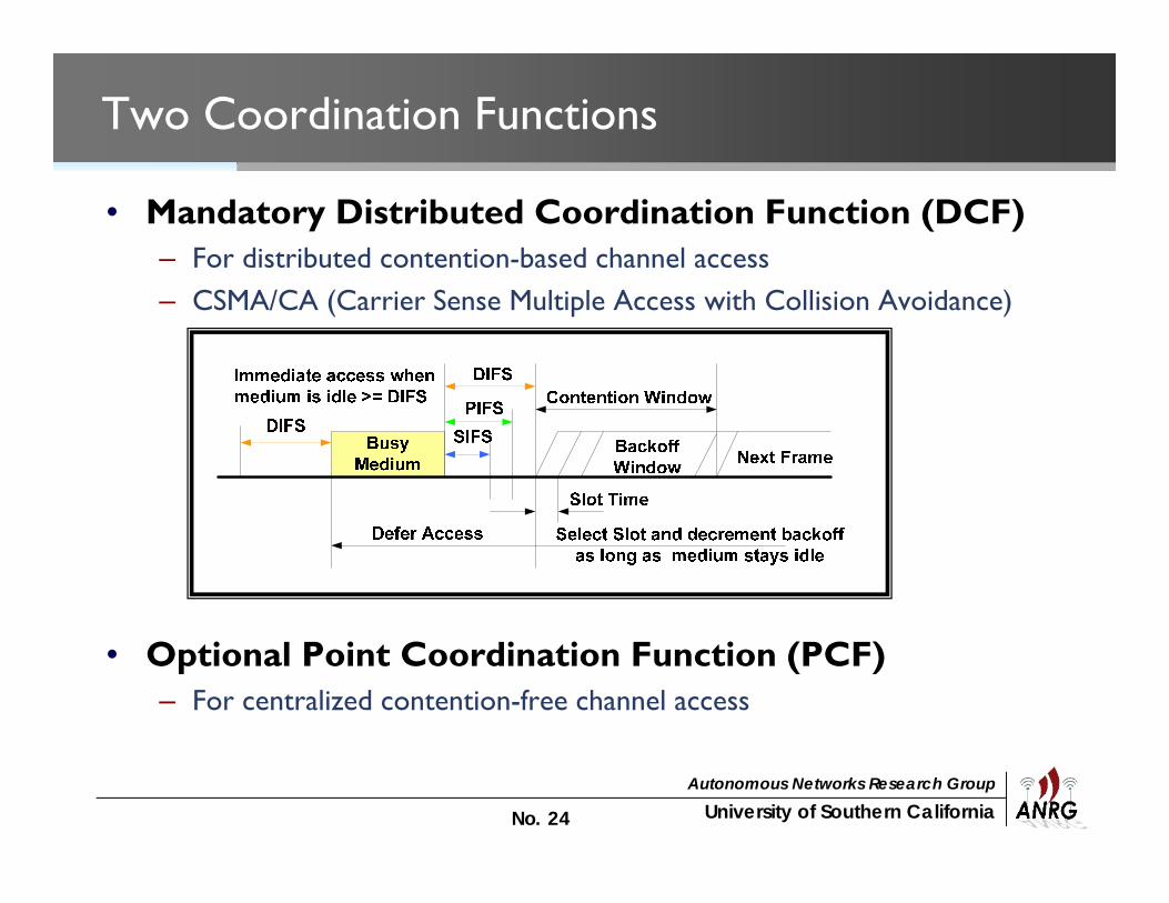
Two Coordination Functions
• Mandatory Distributed Coordination Function (DCF)– For distributed contention-based channel access– CSMA/CA (Carrier Sense Multiple Access with Collision Avoidance)
• Optional Point Coordination Function (PCF)– For centralized contention-free channel access
University of Southern CaliforniaAutonomous Networks Research Group
No. 25
IEEE 802.11 Standards
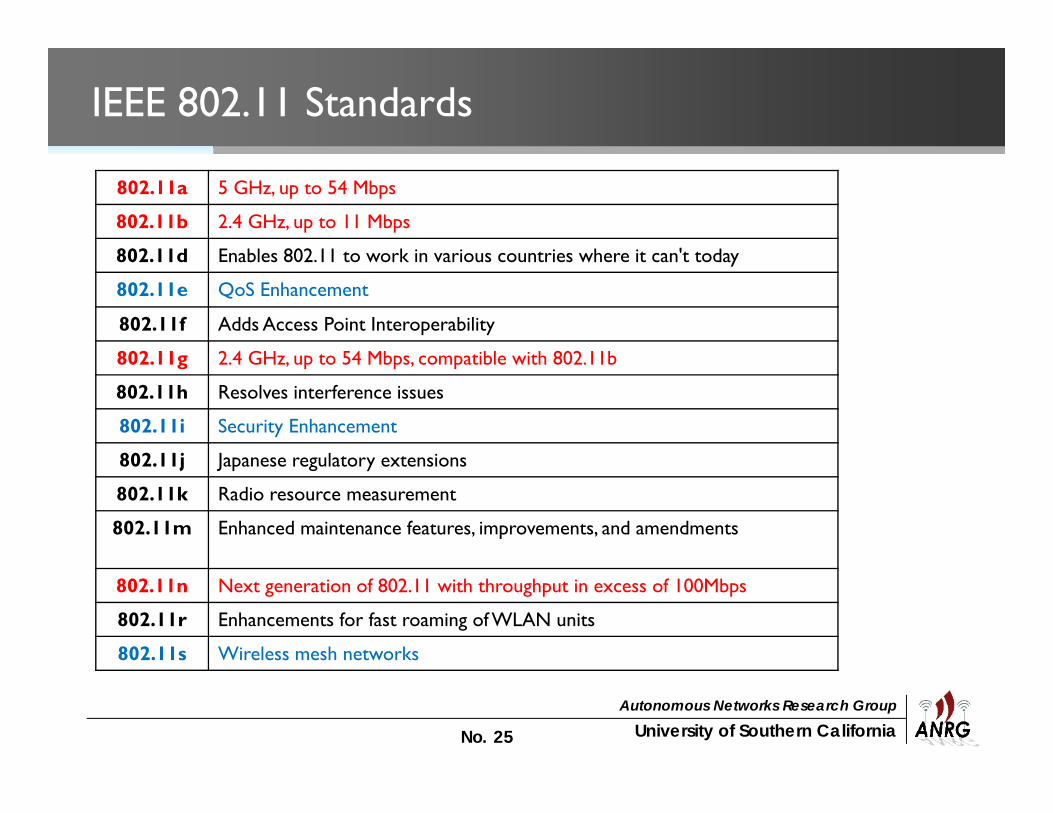
802.11a 5 GHz, up to 54 Mbps
802.11b 2.4 GHz, up to 11 Mbps
802.11d Enables 802.11 to work in various countries where it can't today
802.11e QoS Enhancement
802.11f Adds Access Point Interoperability
802.11g 2.4 GHz, up to 54 Mbps, compatible with 802.11b
802.11h Resolves interference issues
802.11i Security Enhancement
802.11j Japanese regulatory extensions
802.11k Radio resource measurement
802.11m Enhanced maintenance features, improvements, and amendments
802.11n Next generation of 802.11 with throughput in excess of 100Mbps
802.11r Enhancements for fast roaming of WLAN units
802.11s Wireless mesh networks

IEEE 802.11 Physical Layer

University of Southern CaliforniaAutonomous Networks Research Group
No. 27
IEEE 802.11 Physical Layer
• Many physical layer standards– 1997: 802.11 infrared, FHSS, DSSS– 1999: 802.11a OFDM and 802.11b HR-DSSS– 2001: 802.11g OFDM

University of Southern CaliforniaAutonomous Networks Research Group
No. 28
IEEE 802.11 Physical Layer
• 802.11 Infrared– Two capacities 1 Mbps or 2 Mbps.– Range is 10 to 20 meters and cannot penetrate walls.– Does not work outdoors.
• 802.11 FHSS (Frequency Hopping Spread Spectrum)– The main issue was multipath fading.– 79 non-overlapping channels, each 1 Mhz wide at low end of 2.4 GHz
ISM band.– Dwell time: min. time on channel before hopping (400msec).

University of Southern CaliforniaAutonomous Networks Research Group
No. 29
IEEE 802.11 Physical Layer
• 802.11 DSSS (Direct Sequence Spread Spectrum)– Spreads signal over entire spectrum using pseudo-random sequence
(similar to CDMA).– 1 or 2 Mbps.
• 802.11a OFDM (Orthogonal Frequency DivisionalMultiplexing)
– Compatible with European HiperLan2.– 54Mbps in wider 5.5 GHz band transmission range is limited.– Uses 52 FDM channels (48 for data; 4 for synchronization).– Encoding is complex (PSM up to 18 Mbps and QAM above this capacity).

University of Southern CaliforniaAutonomous Networks Research Group
No. 30
IEEE 802.11 Physical Layer
• 802.11b HR-DSSS (High Rate Direct Sequence SpreadSpectrum)– 11a and 11b shows a split in the standards committee.– 11b approved just before 11a and hit the market.– Up to 11 Mbps in 2.4 GHz band.– Range is 7 times larger than 11a.– 802.11b and 802.11a are incompatible!– Note in this bandwidth all these protocols have to deal with interference
from microwave ovens, cordless phones, garage door openers,Bluetooth, Zigbee.
University of Southern CaliforniaAutonomous Networks Research Group
No. 31
IEEE 802.11 Physical Layer
• 802.11g OFDM (Orthogonal Frequency DivisionMultiplexing)– An attempt to combine the advantage of both 802.11a and 802.11b.– Supports speed up to 54 Mbps.– Uses 2.4 GHz frequency for greater range.– Is backward compatible with 802.11b.

IEEE 802.11 Medium Access Control Layer
University of Southern CaliforniaAutonomous Networks Research Group
No. 33
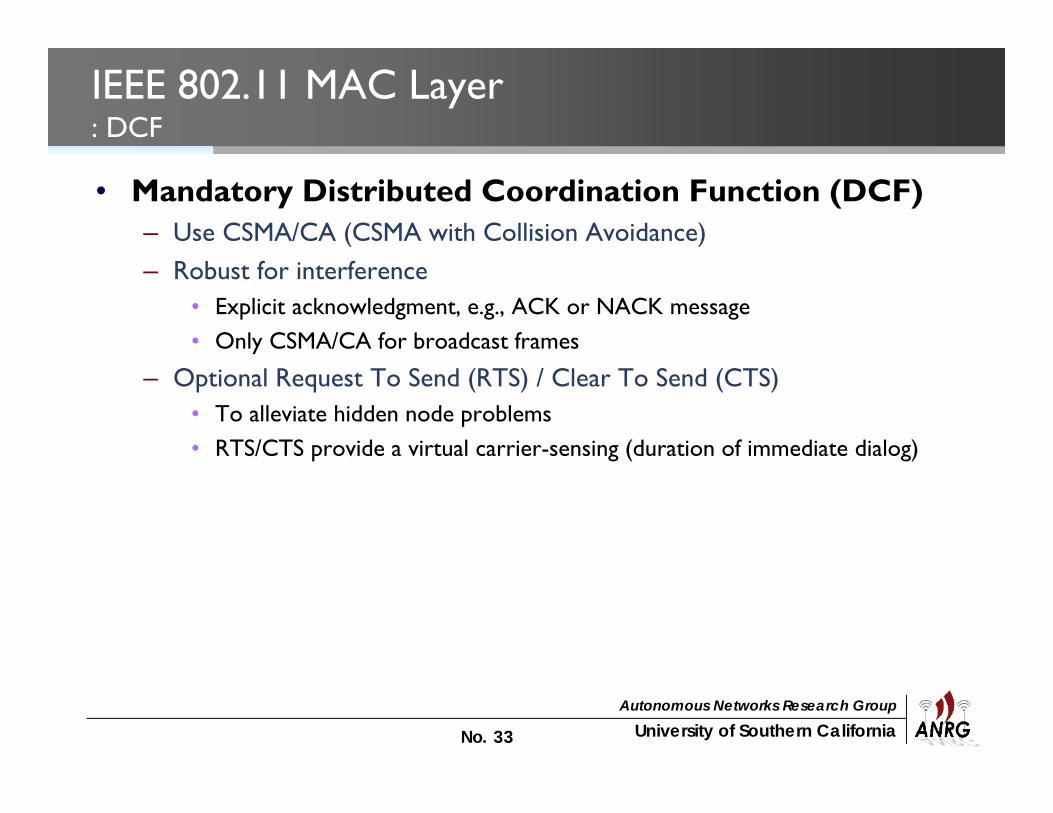
IEEE 802.11 MAC Layer: DCF
• Mandatory Distributed Coordination Function (DCF)– Use CSMA/CA (CSMA with Collision Avoidance)– Robust for interference
• Explicit acknowledgment, e.g., ACK or NACK message• Only CSMA/CA for broadcast frames
– Optional Request To Send (RTS) / Clear To Send (CTS)• To alleviate hidden node problems• RTS/CTS provide a virtual carrier-sensing (duration of immediate dialog)

University of Southern CaliforniaAutonomous Networks Research Group
No. 34 34
CTS = Clear To Send
RTS = Request To Send
Request To Send (RTS) / Clear To Send (CTS)
D
Y
S
M
K
RTS
CTS
X

University of Southern CaliforniaAutonomous Networks Research Group
No. 35 35
Request To Send (RTS) / Clear To Send (CTS)
D
Y
S
X
M
Ksilenced
silenced
silenced
silencedData
ACK

University of Southern CaliforniaAutonomous Networks Research Group
No. 36
IEEE 802.11 MAC Layer: DCF
• Carrier-sensing mechanisms– Physical carrier-sense
• Truly proves the channel• Provided by PHY, and depends on PHY• Clear Channel Assessment (CCA) by PHY
– Virtual carrier-sense• Assume that the channel is busy (irrespective of CCA!) during the time
indicated by the duration field in data frame or in RTS/CTS messages• Adjusts their NAV (Network Allocation Vector) accordingly.

University of Southern CaliforniaAutonomous Networks Research Group
No. 37
DCF Operation
• 1. when the MAC layer receives a request to transmit a data, it checks themedium status based on the physical and virtual carrier sense mechanisms.
• 2. if the medium is not in use for an interval of DIFS, the MAC may begintransmission

University of Southern CaliforniaAutonomous Networks Research Group
No. 38
DCF Operation (Cont’d)
• 3. if the medium is in use during the DIFS interval, the MAC will randomlychoose a backoff value in the range of [0,CW].
• 4. if the medium is detected to be idle for one slot time, the MACdecrements the backoff value each time.
University of Southern CaliforniaAutonomous Networks Research Group
No. 39
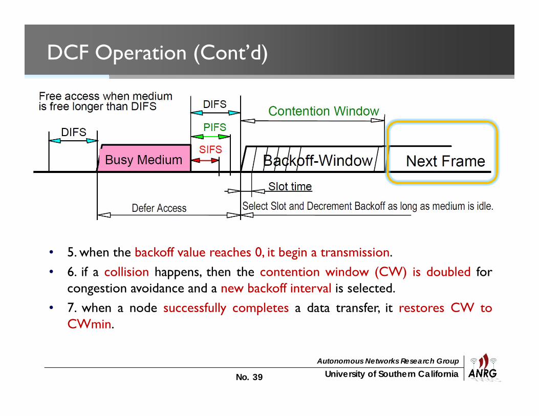
DCF Operation (Cont’d)
• 5. when the backoff value reaches 0, it begin a transmission.• 6. if a collision happens, then the contention window (CW) is doubled for
congestion avoidance and a new backoff interval is selected.• 7. when a node successfully completes a data transfer, it restores CW to
CWmin.

University of Southern CaliforniaAutonomous Networks Research Group
No. 40
IEEE 802.11 MAC Layer: PCF
• Optional Point Coordination Function (PCF)– A centralized collision-free MAC– The AP periodically polls other stations through beacon frame to check
if they have data to send.– The AP may tell another station to sleep to save on batteries.– The PCF can be built over the DCF and both operate simultaneously.

University of Southern CaliforniaAutonomous Networks Research Group
No. 41
PIFS
stations‘NAV
wirelessstations
point coordinator
D1
U1
SIFS
NAV
SIFSD2
U2
SIFS
SIFS
SuperFramet0
medium busy
t1
tstations‘NAV
wirelessstations
point coordinator
D3
NAV
PIFSD4
U4
SIFS
SIFSCFend
contentionperiod
contention free period
t2 t3 t4
IEEE 802.11 MAC Layer: PCF
University of Southern CaliforniaAutonomous Networks Research Group
No. 42
Acknowledgement
• This material was partly adapted from– “Wireless Medium Access Control” by Romit Roy Choudhur at Duke
University– “Wireless LAN 802.11 Tutorial” by Maximilian Riegel at SIEMENS
Mobile


![How Beneficial is the WiFi Offloading? A Detailed Game ... traffic originally targeted for cellular base stations ... a detailed modeling framework for analysing the WiFi ... [12]](https://img.pdfslide.us/doc/110x75/5ab889be7f8b9ad5338ced65/how-benecial-is-the-wifi-ofoading-a-detailed-game-trafc-originally.jpg)