Embed Size (px)
Citation preview

Spray Polyurethane
Foam Insulation Systems
For
Metal Service Vessels
Operating Between
-35 oC (-30
oF) and 93
oC (200
oF)
Copyright 1997 To order copies of this publication call 1-800-523-6154 and request SPFA Stock Number AY-103
SPFA 10/2002 Revised June/ 2004
Recommended Design
Considerations and
Guide Specifications

1
TECHNICAL COMMITTEE
Mission Statement
The mission of the Technical Committee is to provide a wide range of technical service to the Spray
Polyurethane Foam industry such as, but not limited to:
1. Review existing documents and serve as a clearing house to ensure the “Continuity of Value” of technical
information published by SPFA and others concerning the products and services to our industry;
2. Review, research, develop and issue documents concerning new products, systems and services AND
3. To identify, explore, develop and communicate an understanding of technical issues facing our industry.
Technical Committee Members
Roger Morrison, Chairman David Lewis Robert Smith
North Carolina Foam Industries Coastal Coatings Inc. Invita
Mary Bogden Roger Lock John Stahl Honeywell MacTec Engineering and Consulting Preferred Soulutions Inc.
Bob Braun Jack Moore Jay Zhang
Dow Chemical West Roofing Systems, Inc. Convenience Products
John Courier Bruce Schenke AD HOC MEMBERS: Equipment and Coatings Technology BASF
John Hatfield Irene Schwechler Laverne Dalgleish
Penta Engineering Group, Inc. Gaco Western Inc. CUFCA
Dan Hensley Chuck Skalski Scott Brown
Hensley Coating Inc. Gaco Western Inc, BaySystems North America LLC
Tim Leonard Larry Smiley
ERSystems Poly-Tek
This brochure was developed to aid specifiers in choosing spray-applied polyurethane foam systems. The information provided
herein, based on current customs and practices of the trade, is offered in good faith and believed to be true, but is made WITHOUT WARRANTY, EITHER EXPRESS OR IMPLIED, AS TO FITNESS, MERCHANTABILITY, OR ANY OTHER MATTER. SPFA DISCLAIMS ALL LIABILITY FOR ANY LOSS OR DAMAGE ARISING OUT OF ITS USE. Individual manufacturers and contractors should be consulted for specific information. Nominal values which may be provided herein are believed to be representative, but are not to be used as specifications nor assumed to be identical to finished products. SPFA does not endorse the proprietary products or processes of any individual manufacturer, or the services of any individual contractor.

2
Table of Contents
Design Consideration Page
Surface Preparation, Procedures and Considerations ................................................................................................................................... 4
1. General Surface Preparation Procedures .............................................................................................................................. 4
2. Painted Iron and Steel Surfaces ............................................................................................................................................ 4
3. Ferrous Metal Surfaces ......................................................................................................................................................... 4
4. Other Metal Surfaces ............................................................................................................................................................ 4
Selection of Metal Primer and/or Coating System ........................................................................................................................................ 4
Selection of the Polyurethane Foam System ................................................................................................................................................. 5
Selection of a Protective Coating .................................................................................................................................................................. 5
1. Physical Characteristics ........................................................................................................................................................ 5
2. Performance Characteristics ................................................................................................................................................. 5
Additional Design Considerations ................................................................................................................................................................. 5
Cold Vessel Pull Down Schedule .................................................................................................................................................................. 5
Maintenance Procedures ................................................................................................................................................................................ 5
Guide Specification for Polyurethane Foam Insulation Systems to Metal Service Vessels
Operating Between –35 oC (-30
oF) and 93
oC (200
oF)
Part 1 – General
1.01 Scope of Work .................................................................................................................................................................. 6
1.02 Related Work Specified Elsewhere ................................................................................................................................... 6
1.03 Quality Assurance ............................................................................................................................................................. 6
1.04 Submittals ......................................................................................................................................................................... 6
1.05 Materials, Delivery and Storage........................................................................................................................................ 7
1.06 Environmental Conditions ................................................................................................................................................ 7
1.07 Sequencing and Scheduling .............................................................................................................................................. 7
1.08 Warranty ........................................................................................................................................................................... 7
1.09 Safety Requirements ......................................................................................................................................................... 7
Part 2 – Products
2.01 Polyurethane Foam ........................................................................................................................................................... 7
2.02 Protective Coating ............................................................................................................................................................. 8
Part 3 – Execution
3.01 Surface Preparation, Metal Priming and Coating.............................................................................................................. 8
3.02 Primer and Metal Coating Applications ............................................................................................................................ 9
3.03 Polyurethane Foam Application........................................................................................................................................ 9
3.04 Protective Coating Application ....................................................................................................................................... 10
3.05 Safety Requirements ....................................................................................................................................................... 11
Appendix
Guide Specifications for the Repair of Polyurethane Foam Insulation System for Metal Storage Vessels
1.0 Scope of Work ................................................................................................................................................................ 12
2.0 Surface Preparation ......................................................................................................................................................... 12
3.0 Repair Procedures ........................................................................................................................................................... 12
Illustrations Detail 1 Standard Protrusion Detail .............................................................................................................................................. 13
Detail 2 Vertical Wall Protrusion Detail for Above Ambient and Below 93 oC (200
oF) where Service Access is Required ..... 14
Detail 3 Insulation of Flashing for High Temperature Protrusion {Excess of 93 oC (200
oF) ...................................................... 15
Detail 4 Insulation of Vessel Cradles and Supports...................................................................................................................... 16
Detail 5 Typical Installations – Shell, Roof Junction and Base .................................................................................................... 17
Detail 6 Insulation of Vessel Lugs and Supporting Steel ............................................................................................................. 18
Detail 7 Insulation of Vessel Leg ................................................................................................................................................. 19
Detail 8 Insulation of Vessel Nozzles ........................................................................................................................................... 20
Detail 9 Repair with Spray Applied Polyurethane Foam (SPF) ................................................................................................... 21

3
Photos
Photo 1 Polyurethane Foam Texture – Smooth ............................................................................................................................ 22
Photo 2 Polyurethane Foam Texture – Orange Peel .................................................................................................................... 22
Photo 3 Polyurethane Foam Texture – Coarse Orange Peel ........................................................................................................ 22
Photo 4 Polyurethane Foam Texture – Rippling – Verge of Popcorn .......................................................................................... 23
Photo 5 Polyurethane Foam Texture – Popcorn ........................................................................................................................... 23
Photo 6 Polyurethane Foam Texture – Treebark .......................................................................................................................... 23
DESIGN CONSIDERATIONS
GENERAL CONSIDERATIONS
The performance of a spray applied polyurethane
foam insulation system can be affected by all the component
parts of a vessel, as well as the conditions inside and outside
the vessel.
Proper structural design, specification review,
contractor and material selection, coupled with the
compatibility and positioning of the various components of the
insulation system are a necessity to produce a successful
insulation system.
Consult with the respective material suppliers and the
successful contractor to receive written confirmation of their
agreement to all facets of the insulation system, including, but
not limited to, material selection, surface preparation, metal
primer, coating, design details, etc.
SURFACE PREPARATION, PROCEDURES
AND CONSIDERATIONS
The following general practices must be observed on all metal
surfaces which are to receive spray polyurethane foam:
1. General Surface Preparation Procedures
A. Prior to the application of primer or polyurethane
foam, the substrate shall be dry and free of any
contaminants that may interfere with proper adhesion
of any of the respective components.
B. Surface contaminants, depending on their severity
and quantity, may be removed by use of air pressure,
vacuum equipment, hand power broom, chemical sol-
vents, gritblasting, manual scraping, etc.
C. Rough welds and other sharp projections shall be
ground smooth. All flux, slag, or other lamination left
from welding must be chipped or ground off and spot
striped or primed.
D. Name plates, valve stems, rotating equipment, etc.
shall be protected from gritblasting and overspray by
suitable masking materials.
E. Gritblasted surfaces shall be coated before visible
rusting occurs. In all cases the metal will be primed
or coated the same day it is gritblasted.
2. Painted Iron and Steel Surfaces
A. If a significant amount of the existing coating, paint,
or primer has failed, can be easily scraped off, or
exhibits extreme chalking, the entire coating, paint or
primer shall be completely removed. Gritblasting is
recommended. All items listed under "Recommended
Gritblasting Procedures" should be followed.
B. Gritblasting is not required on surfaces where the
existing coating, paint or primer exhibits sound
physical properties, good adhesion and is compatible
with the proposed polyurethane foam insulation
system. Follow manufacturer's recommendations
3. Ferrous Metal Surfaces
A. All surfaces shall be gritblasted in accordance with
SSPC SP-6, Commercial Blast Cleaning (Surface
Preparation Specifications Steel Structures Painting
Council SSPC Publication No. 91-08.)
B. Prime and/or coat gritblasted surfaces in accordance
with polyurethane foam and/or primer/coating
manufacturers' instructions and recommendations.
4. Other Metal Surfaces
A. Clean galvanized metal, aluminum, copper and stain-
less steel surfaces as recommended by the poly-
urethane foam and/or primer/coating manufacturer.
Abrasive blasting may be necessary to achieve
adequate primer/coating adhesion.
B. Prime galvanized metal, aluminum, copper and stain-
less steel surfaces as recommended by the poly-
urethane foam and/or primer/coating manufacturer.
C. Contact polyurethane foam and/or primer/coating
manufacturer for recommendations to prepare other
metal surfaces.
SELECTION OF METAL PRIMER AND/OR
COATING SYSTEM
The following items should be considered when
choosing a metal primer and/or coating system.
A. Surface preparation required.

4
B. Adhesion to substrate.
C. Adhesion to polyurethane foam.
D. Maximum and minimum vessel temperatures.
E. Corrosion resistance to vessel contents or vapors.
F. Polyurethane foam and/or primer/coating
manufacturer’s recommendation.

5
SELECTION OF THE POLYURETHANE
FOAM SYSTEM
The contractor, in the case of spray polyurethane
foam applications, is fabricating the product on site in
accordance with the manufacturers' instructions.
A wide range of polyurethane foam systems are
available in various performance properties, each exhibiting
different temperature limitations, combustibility
characteristics, etc. The use of these systems in combination
with each other or with other conventional insulation products
offer a wide range of economical installations.
Most published data is run on laboratory produced
samples. The thickness of polyurethane foam sprayed, number
of passes, temperatures of substrate, ambient temperatures,
etc. have a pronounced effect on all properties.
From a fire safety standpoint, polyurethane foams
can be used safely. It is important, however, that all persons
associated with the design, fabrication, storage and installation
under- stand the material and environments involved.
Polyurethane foam insulation is combustible and
should be treated as such. Flame spread ratings provided
for polyurethane products using small scale tests are not
intended to reflect the hazards presented by this or any
other materials under actual fire conditions.
This specification is not applicable where severe
thermal shock is possible. Discuss with your contractor and
systems manufacturer the heat-up and/or cool down
procedures, including expansion or contraction details, etc., to
be used on each vessel.
SELECTION OF A PROTECTIVE COATING
A protective coating system must be applied to the
polyurethane foam as an integral part of the vessel insulation
system.
The protective coating shall be a system which will
cure to form a water resistant protective membrane. The dry
film thickness (DFT) of the protective coating shall be in
compliance with the coating manufacturer's specification.
On many vessels, or portions thereof, fireproofing
over the insulation system may be required. If fireproofing is
required, consult your selected contractor for the
recommended procedure to accomplish the same.
Consider the following items in the selection of the
coating materials:
1. Physical Characteristics
A. Chemical resistance.
B. Water vapor permeance.
C. Tensile and elongation properties.
D. Retention of physical properties upon aging.
E. UV resistance.
2. Performance Characteristics
A. Environment in which to be used (abrasion and
impact).
B. Life Expectancy.
C. Ease of maintenance.
D. History of similar applications or laboratory data
relating to the application in question.
E. Adhesion to the polyurethane foam.
F. Combustibility characteristics, individually and
in combination with the selected polyurethane
foam systems.
G. Aesthetic qualities.
ADDITIONAL DESIGN CONSIDERATIONS
1. Before applying polyurethane foam and
protective coatings, protect individuals and areas
from the application of material by masking and
sealing of air intakes into buildings that may be
affected. Take pre-cautions to avoid
concentrations of fumes in occupied areas.
2. Best results will be obtained when polyurethane
foam is applied to a warm substrate (40 oC to 60
oC [100
oF to 140
oF]). Consult your
manufacturer for specific recommendations.
3. Temperature sensing indicators can be installed
to help monitor maximum tank temperature.
4. Use the following pull down schedule for
insulated vessels operating at temperatures under
0 oC (32
oF):
COLD VESSEL PULL DOWN SCHEDULE
Materials used to construct and insulate cold storage
vessels are affected by temperature changes. Gradual lowering
of the temperature is designed to eliminate problems
stemming from these temperature changes.
Reduce temperature 6 oC (10
oF) every 24 hours until
the operating temperature is reached.
MAINTENANCE PROCEDURES
It is strongly recommended that maintenance
procedures, including annual inspections, be established with
your selected contractor for any insulation system to yield its
full value.
CONTACT THE RESPECTIVE MANUFACTURERS/SUPPLIERS
AND CONTRACTORS FOR THEIR RECOMMENDED
MAINTENANCE PROCEDURES.

6
GUIDE SPECIFICATION FOR POLYURETHANE FOAM
INSULATION SYSTEMS TO METAL SERVICE VESSELS OPERATING
BETWEEN -35
oC ( -30
oF) AND 93
oC (200
oF)
NOTE: This guide is designed to help the specifier achieve a successful polyurethane foam insulation system. It is the responsibility of
the specifier to consult with manufacturer of material specified as to the manufacturer's specific recommendations.
PART I - GENERAL
This guide discusses the application of a seamless spray polyurethane foam with a protective coating for use as an insulation system
for metal service vessels. Your contractor, selected systems manufacturer and regulatory agencies can assist you, as each project must
be assessed individually.
1.01 SCOPE OF WORK
Furnish all labor, material, tools and equipment necessary for the application of a polyurethane foam insulation system,
including accessory items, subject to the general provisions of the contract.
1.02 RELATED WORK SPECIFIED ELSEWHERE
A. Metals-Metal Fabrications Section 05500
B. Vapor and Air Retarders Section 07190
C. Insulation Section 07200
D. Fireproofing Section 07250
E. Special Coatings Section 09800
F. Special Construction-Liquid and Gas Storage Tanks Section 13200
1.03 QUALITY ASSURANCE
A. Contractor Qualifications: The contractor should provide information concerning projects similar in nature to the one
proposed including location and person to be contacted. SPFA accredited companies are recommended. Some
manufacturers of spray polyurethane foam systems and/or protective coatings have approval programs.
B. Manufacturer Qualifications: Polyurethane foam and protective coating manufacturers shall show evidence of sufficient
financial resources and manufacturing facilities to furnish materials on this project. References shall be required,
sufficient project lists and warranties shall be submitted for verification.
C. Inspections: An inspection of the finished insulation system by the polyurethane foam and/or protective coating
manufacturer, or third party inspector is recommended.
1.04 SUBMITTALS
A. Manufacturers published data sheets or letter of certification that their products comply with the materials specified. This
is to include primers, metal coating systems, polyurethane foam, thermal barriers and protective coatings.
B. Shop drawings on accessories, design details, and fabricated items.
C. Manufacturers' application or installation instructions.
D. Evidence of contractor/applicator qualification and experience.
E. A specimen copy of the applicable warranty for the project.
F. Safety and handling instructions for storage, handling, and use of the materials to include appropriate Materials Safety
Data Sheets (MSDS).
7
1.05 MATERIALS, DELIVERY AND STORAGE
A. Material shall be delivered in the manufacturer's original, tightly sealed containers or unopened packages, all clearly
labelled with the manufacturer's name, product identification, safety information, and batch or lot numbers where
appropriate.
B. Containers shall be stored out of the weather and direct sun where the temperatures are within the limits specified by the
manufacturer.
C. All materials shall be stored in compliance with local fire and safety requirements.
1.06 ENVIRONMENTAL CONDITIONS
A. The polyurethane foam applications shall not proceed during periods of inclement weather. Do not apply the
polyurethane foam below the temperature and/or above humidity specified by the manufacturer for ambient air and
substrate.
B. Do not apply protective coatings when there is ice, frost, surface moisture or visible dampness present on the surface to
be coated. Prior to applying the coatings, check the polyurethane foam to insure that the surface is dry. Apply protective
coatings in accordance with the coating manufacturer's application instructions.
C. Wind barriers may be used if wind conditions could affect the quality of the polyurethane foam or protective coating
installation.
1.07 SEQUENCING AND SCHEDULING
In vessel insulation projects the spray polyurethane foam is installed when all welding is complete, and the metal surface is
prepared according to specification. There should not be any other trades-people working on the vessel when the spray
polyurethane foam and coating are being installed.
1.08 WARRANTY
Warranty agreements vary in duration and content. If a warranty is desired, it is suggested that parameters be established as a
prerequisite to the execution of a contract.
1.09 SAFETY REQUIREMENTS
A. See API Bulletin AX-119, "MDI-Based Polyurethane Foam Systems: Guidelines for Safe Handling and Disposal."
B. Refer to appropriate Materials Safety Data Sheets (MSDS).
C. Take precautions to avoid concentrations of fumes in occupied areas.
PART 2 – PRODUCTS
2.01 POLYURETHANE FOAM
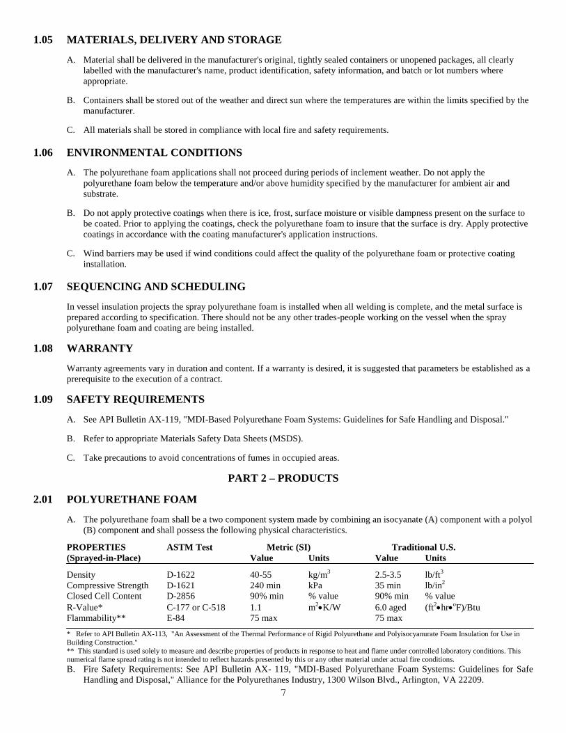
A. The polyurethane foam shall be a two component system made by combining an isocyanate (A) component with a polyol
(B) component and shall possess the following physical characteristics.
PROPERTIES ASTM Test Metric (SI) Traditional U.S.
(Sprayed-in-Place) Value Units Value Units
Density D-1622 40-55 kg/m3 2.5-3.5 lb/ft
3
Compressive Strength D-1621 240 min kPa 35 min lb/in2
Closed Cell Content D-2856 90% min % value 90% min % value
R-Value* C-177 or C-518 1.1 m2K/W 6.0 aged (ft
2hr
oF)/Btu
Flammability** E-84 75 max 75 max
* Refer to API Bulletin AX-113, "An Assessment of the Thermal Performance of Rigid Polyurethane and Polyisocyanurate Foam Insulation for Use in
Building Construction."
** This standard is used solely to measure and describe properties of products in response to heat and flame under controlled laboratory conditions. This numerical flame spread rating is not intended to reflect hazards presented by this or any other material under actual fire conditions.
B. Fire Safety Requirements: See API Bulletin AX- 119, "MDI-Based Polyurethane Foam Systems: Guidelines for Safe
Handling and Disposal," Alliance for the Polyurethanes Industry, 1300 Wilson Blvd., Arlington, VA 22209.

8
2.02 PROTECTIVE COATING
A. The Elastomeric Coating System may be one or more of following types:
1. Acrylic
2. Butyl Rubber
3. Hypalon
4. Neoprene
5. Silicone
6. Polyurethane Elastomer
7. Modified Asphalt
B. Physical Properties: The Elastomeric Coating System shall possess the following physical characteristics. (NOTE:
Specifier shall list physical properties of chosen Elastomeric Coating System):
PROPERTIES ASTM TEST VALUE
Tensile Strength D-412
Elongation D-412
Hardness Shore A D-2240
Tear Resistance D-624
UltraViolet Exposure G-53
Moisture Vapor Transmission E-96 Procedure E
Chemical Resistance D-1308
C. General: It is recommended that the coating systems be elastomeric in nature (at least 100% elongation.) Within these
generic coatings are both vapor retarder and non vapor retarder systems.
Cold tanks require a vapor retarder coating. For further information regarding perm ratings and coating selection see
"Moisture Vapor Transmission" paper. [SPFA Stock number AY-118]
For further information concerning protective coatings refer to "A Guide for Selection of Protective Coatings Over Sprayed
Polyurethane Foam Roofing Systems." [SPFA Stock number AY-102]
2.03 RELATED PRODUCTS
A. Flashings and waterproof coverings for flexible joints shall be compatible with specified polyurethane foam and
elastomeric coating system and shall be as recommended by the manufacturers of the systems used.
B. Miscellaneous materials such as adhesives, elastomeric caulking compounds, metal, insulation blankets etc. shall be a
composite part of the insulation system and shall be those recommended by the systems manufacturer.
C. Primers, metal coatings and thermal barriers shall be as recommended by the respective manufacturers.
PART 3 - EXECUTION
3.01 SURFACE PREPARATION, METAL PRIMING AND COATING
A. Ferrous Metal:
1. Gritblast iron and steel surfaces which are not primed, painted, or otherwise protected in accordance with SSPC SP-
6, Commercial Blast Cleaning. This includes stairs, tank connecting nozzles, and other items that are a part of the
vessel and will have the polyurethane foam insulation system applied to portions of it.

9
2. Remove contaminants from metal surfaces.
3. Apply primer before surface rust develops. if surface rust develops, gritblast surface again.
4. All bolts, welds, sharp edges and difficult access areas shall receive a primer spot-coat prior to metal primer/coating
system.
5. Apply metal primer/coating system according to manufacturer's instructions.
B. Aluminum, Stainless Steel, Galvanized Metal
Clean surface in accordance with SSPC-1, Solvent Cleaning or Steam Cleaning. If polyurethane foam and/or metal
primer/coating manufacturer recommends gritblasting, clean surface in accordance with SSPC-7, Brush-Off Blast
Cleaning.
3.02 PRIMER AND METAL COATING APPLICATION
A. Inspection
1. Prior to the application of the metal primer/coating system, the surface shall he inspected to insure that conditions
required by Section 3.01 have been met.
2. The metal primer/coating system application shall not proceed during periods of inclement weather. The applicator
shall not apply the coatings below the temperature and/or humidity specified by the manufacturer for ambient air
and substrate.
B. Application
1. The metal primer/coating system shall be applied in accordance with the manufacturer's specification and
instructions.
2. The metal primer/coating shall be allowed to cure sufficiently before subsequent coats or polyurethane foam is
applied and will be within the recoat schedule recommended by the respective manufacturers.
3. Inspect the metal primer/coating system for holidays and adequate dry film thickness before subsequent coats are
applied. Any damage or defects to the metal primer/coating system shall be repaired before the polyurethane foam
application.
4. The metal primer/coating system shall be free of contaminants and holidays before the application of polyurethane
foam.
3.03 POLYURETHANE FOAM APPLICATION
A. Inspection
1. Prior to the application of the polyurethane foam, the surface shall be inspected to insure that conditions required by
Section 3.02 have been met.
2. The polyurethane foam application shall not proceed during periods of inclement weather. The applicator shall apply
the polyurethane foam within the temperature and/or humidity limits specified by the manufacturer for ambient air
and substrate. Wind barriers should be used if wind conditions could affect the quality of installation.
B. Application
1. Prior to spray application, all surfaces not be insulated should be protected from overspray.
2. The spray polyurethane foam shall be applied in accordance with the manufacturer's specification and instructions.

10
3. The spray polyurethane foam shall be applied in minimal pass thicknesses of 13 mm (1/2 inch).
4. Spray polyurethane foam thickness shall be a minimum of 25 mm (I inch) or more if specified. The polyurethane
foam shall be applied uniformly over the entire surface with a tolerance of plus 6 mm per 25 mm (1/4 inch per inch)
of thickness minus 0 mm (O inches) except where variations are required to insure proper drainage or to complete a
feathered edge.
5. The polyurethane foam shall be uniformly terminated 100 mm (4 inches) beyond all projections, nozzles, pipes,
flanges. etc.
6. The polyurethane foam shall be applied over vessel roofs in a manner to provide drainage and prevent standing
water.
7. When equipment is supported by structural members, the polyurethane foam shall extend at least 4 times the
specified insulation thickness in each direction, measured from junction of equipment with insulated support lug.
Thickness of polyurethane foam on steel supports shall be 1/2 of that specified for the body of the equipment.
Thickness of polyurethane foam over support lugs will be the same as specified for the body of the equipment. (See
Details #4, #6)
8. Skirts supporting vertical equipment shall be insulated inside and outside as part of the equipment area.
Polyurethane foam is to extend from the junction at the inside of the skirt down at least one foot. (See Detail # 7)
9. Heads, manholes, blind flanges, etc., that must be removed occasionally should be insulated so that they can be
removed without damage to the insulation. (See Detail # 8)
10. Where temperatures exceed 93 ºC (200º F), a high temperature insulation blanket shall be installed prior to the
polyurethane foam application.
11. The full thickness of polyurethane foam in any area shall be completed prior to the end of each day. If more than 24
hours elapse between the polyurethane foam lifts, the polyurethane foam shall be examined for UV degradation,
oxidation, or contamination. The surface shall be prepared according to the manufacturer's recommendations.
C. Surface Finish
1. The final spray polyurethane foam surface shall be "smooth, orange peel, coarse orange peel. or verge of popcorn"
Polyurethane foam surfaces termed '.popcorn" or "treebark" are not acceptable and should be corrected. (See surface
texture photos)
2. Any damage or defects to the polyurethane foam shall be repaired prior to the protective coating application.
3. The polyurethane foam surface shall be free of contaminants that will impair adhesion of the protective coating
system.
3.04 PROTECTIVE COATING APPLICATION
A. Inspection
Prior to the application of the protective coatings, the polyurethane foam shall be inspected to insure that conditions
required by Section 3.03 have been met.
B. Application
1. Base Coat
a. The base coat shall be applied the same day as the polyurethane foam when possible. If more than 24 hours
elapse prior to the application of the base coat, the polyurethane foam shall be inspected for UV degradation,
oxidation, and contaminants. The manufacturer's recommendations shall be followed to prepare the foam
surface before coating applications.

11
b. The base coat shall be applied at a uniform thickness with the rate of application governed by the polyurethane
surface texture. Coatings shall be applied at a rate to achieve the minimum dry film thickness specified by the
protective coating manufacturer.
c. The coating shall be allowed to cure and be inspected for pinholes, thinly coated areas, uncured areas or other
defects. Defects shall be repaired prior to subsequent applications.
d. Coating will be reinforced in accordance with manufacturer's instructions around protrusions, stairs, etc.
e. The coating application shall not proceed during periods of inclement weather. The applicator shall apply the
protective coating within the temperature and the humidity specified by the manufacturer for ambient air and
substrate. Wind barriers should be used if wind conditions could affect the quality of installation.
2. Top Coat and/or Subsequent Coat
a. Inspect the base coating for defects and thin coating. Make repairs before applying subsequent coats.
b. Subsequent coating should be applied in a timely manner to insure proper adhesion between coats.
c. Final coat shall be inspected for defects and thin coating. Make repairs in accordance with manufacturer's
instructions.
3.05 SAFETY REQUIREMENTS
A. See API Bulletin AX-119,"MDI-Based Polyurethane Foam Systems: “Guidelines for Safe Handling and Disposal."
B. Refer to appropriate Materials Safety Data Sheets (MSDS) for additional safety information.
C. Before applying polyurethane foam and protective coatings, protect adjacent areas and personnel from overspray. Take
precautions to avoid concentration of fumes in occupied areas.

12
APPENDIX 1
GUIDE SPECIFICATIONS FOR THE REPAIR OF A
POLYURETHANE FOAM INSULATION SYSTEM FOR
METAL STORAGE VESSELS
1.0 SCOPE OF WORK
This guide specification covers the repair of spray applied polyurethane foam insulation applied to metal vessels.
2.0 SURFACE PREPARATION
A. Defective polyurethane foam shall be removed at a 45 degree angle in all directions to dry, solidly adhered polyurethane
foam.
B. If existing metal primer/coating is damaged, it shall be wire brushed and recoated according to manufacturer's
instructions.
C. Protect surrounding area from overspray.
D. Vessels in operation may have condensation or ice on the metal substrate. Contact polyurethane foam manufacturer for
instructions if unit cannot be shut down.
3.0 REPAIR PROCEDURE
A. Apply polyurethane foam in the prepared area according to procedure outlined in Section 3.03 so that it conforms to the
existing configuration of the vessel.
B. Apply subsequent coating according to procedures outlined in Section 3.04. A reinforcing fabric may be installed with
the base coat if desired.
C. All areas shall be repaired in a manner to prevent standing water and promote drainage.
D. All prepared areas shall be repaired the same day or adequately protected against moisture or other contaminants.

13
DETAIL ILLUSTRATION

14

15

16

17

18

19

20

21

22

23

24
For More Information
Spray Polyurethane Foam Alliance 4400 Fairlakes Court, Suite 105
Fairfax, VA 22033 800-523-6154