Embed Size (px)
Citation preview

ARIZONA DEPARTMENT OF TRANSPORTATION
REPORT NUMBER: FHWA-AZ88-278
PRESENT STATUS OF MANAGEMENT AND TECHNICAL PRACTICES ON ALLUVIAL FAN AREAS IN ARIZONA
State of the Art
Final Report
Prepared by: Robert L. Ward Consulting Engineer 706 North Gentry Circle Mesa, Arizona 85203
November 1988
Prepared for: Arizona Department of Transportation 206 South 17th Avenue Phoenix, Arizona 85007
in cooperation with U.S. Department of Transportation Federal Highway Administration

The contents of th i s report r e f l ec t the views of the authors who are responsible fo r the fac t s and the accuracy of the data presented herein. The contents do not necessarily re f l ec t . the off ic ia l views or policies of the Arizona Department of Transportation or the Federal Highway Administration. This report does not consti tute a standard, specification, o r regulation. Trade or maqufacturers' names which may appear herein are ci ted only because they are considered essential to the objectives of the report. The U . S . Government and The State of Arizona do n o t endorse products or manufacturers.
TECHNICAL REPORT DOCUMENTATION PAGE
Present Status o f Management and Technical Pract ices on A1 l u v i a l Fan Areas i n Arizona
1. REPORT NO. 1 FHWA-AZ88-278
4 . TITLE AND SUBTITLE
6. PERFORMING ORGANIZATION CODE
2. GOVERNMENT ACCESSION NO. . 3. RECIPIENTS CATALOG NO.
5. REPORT DATE
I
7. AUTHOR(S) 8. PERFORMING ORGANIZATION REPOaT NO.
I Robert L. Ward I I
1 706 North Gentry C i r c l e '
- 11 I . CONTRACT OR GFLANT NO. 1
I
9. ERFORMING ORGANIZATION NAYEAND ?DRESS 6obert L. Ward, Consu t i n g nqineer
ARIZONA DEPARTMENT OF TWNSPORTATION 206 S. l T T H AVENUE PHOENIX, ARIZONA 85007
10. WORK UNIT NO.
Mesa, Arizona 85203
12. SPONSORING AGENCY NAME AND ADDRESS
I Ju ly 1987 - ~obember 1988 1
HPR-PL-l(31) I tem 278 13. N P E OF REPORT & PERIOD COVERED
D r a f t F i na l R e ~ o r t
1
14. SPONSORING AGENCY CODE
I
15. SUPPLEMENTARY NOTES
Prepared in cooperalion wilh the U.S. Department of Transportalion, Federal Highway Administralion
116. ABSTRACT
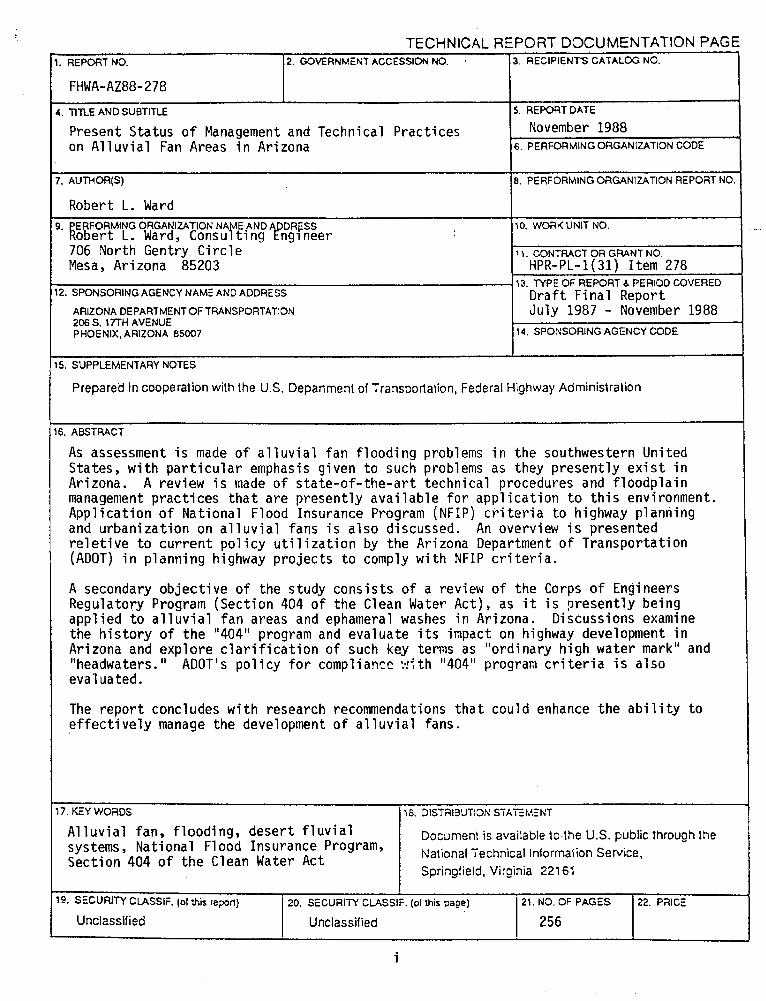
As assessment i s made o f a l l u v i a l f an f l ood ing problems i n the southwestern Uni ted States, w i t h p a r t i c u l a r emphasis g iven t o such problems as they p resen t l y e x i s t i n Arizona. A review i s made o f s ta te -o f - the -a r t technica l procedures and f loodp la in management p rac t i ces t h a t a re present ly a v a i l a b l e f o r a p p l i c a t i o n t o t h i s environment. App l i ca t ion o f Nat iona l Flood Insurance Program (NFIP) c r i t e r i a t o highway planning and u rban iza t ion on a l l u v i a l fans i s a l so discussed. An overview i s presented r e l e t i v e t o cu r ren t p o l i c y u t i l i z a t i o n by the Arizona Department o f Transpor ta t ion (ADOT) i n p lanning highway p ro j ec t s t o comply w i t h NFIP c r i t e r i a .
A secondary ob jec t i ve o f the study cons is ts o f a review o f the Corps o f Engineers Regulatory Program (Sect ion 404 o f the Clean Water Act) , as i t i s p resen t l y being app l ied t o a l l u v i a l f a n areas and ephameral washes i n Arizona. Discussions examine the h i s t o r y o f the "404" program and eva luate i t s impact on highway development i n Arizona and exp lo re c l a r i f i c a t i o n o f such key terms as "ord inary h i gh water mark" and "headwaters. " ADOT's po l i c y f o r compliance v!f t h "404" program c r i t e r i a i s a lso evaluated.
The repo r t concludes w i t h research recommendations t h a t could enhance the abi 1 i t y t o e f f e c t i v e l y manage the development o f a1 l u v i a l fans.
A1 l u v i a l fan, f lood ing, deser t f l u v i a1 systems, Nat ional Flood Insurance Program, Sect ion 404 o f t he Clean Water Act
Document is available to,the U.S. public through the National Technical Informalion Service, Springfield, Virginia 221 61
I
15. SECURITY CUSSIF. (01 rhis repon)
Unclassified .
i
20. SECURITY CLASSIF. (01 this page) 21. N3. OF PAGES
Unclassified 1 211 22. PaICE

Table of Contents
1 INTRODUCTION ........................................................................................ 1
2 DESERT GEOMORPHOLOCY ...................................................................... 7 2.1 The Desert Profile ........................................................................ 8 2.2 The Alluvial Fan ............................................................................. 10
2.2.1 Alluvial Fan Terminology ......................................................... 12 2.2.2 Alluvial Fan Morphology .......................................................... 15 2.2.3 Mechanisms of Alluvial Fan Deposition ................................... 21 2.2.4 Alluvial Fan Dissection ....................... .. .............................. 24
2.3 Pediments ........................................................................................ 30
3 NATIONAL FLOOD INSURANCE PROGRAM ACTIVITY IN ARIZONA .............. 36 3.1 Federal Program ............................................................................... 37 3.2 State Program .................................................................................. 40
3.2.1 State-Owned Lands .................................................................. 40 3.2.2 State Flood Control Assistance Programs ................................. 40 3.2.3 State Coordinating Agency ....................................................... 41
3.3 Local Programs ................................................................................. 43 3.4 ADOT and t h e NFIP .................................. .. 45 ...................................
3.4.1 Federal-Aid Highway Program .................................................. 45 3.4.2 Non-Federal-Aid Highway Program .......................................... 47
4 ROAD DAMAGE AND MAINTENANCE COSTS ON ALLUVIAL FANS ............... 50 4.1 Highway System Damage Categories ............................................... 51 4.2 General Comments/Recommendations ................................................. 63
5 ENGINEERING AND REGULATORY PROBLEMS ON ALLUVIAL FANS ............. 58 5.1 NFIP Problems on Alluvial Fans .................................................... 60 5.2 Local Floodplain Policies Adopted for Alluvial Fans ....................... 63 5.3 Local Technical Procedures for Alluvial Fan Analyses ................... 65 5.4 Critique of Alluvial Fan Regulatory Environment in Arizona ......... 69
6 TECHNICAL PROCEDURES FOR ANALYZING ALLUVIAL FANS ...................... 72 6.1 FEMA Procedure ............................................................................... 73 6.2 Edwards and Thielmann Procedure. Cabazon. California .................. 87 6.3 Federal lnsurance Administration . 1980 Experimental Procedure .... 91 6.4 Soil Conservation Service Procedure ........................................... 97 6.5 Simulation Or Alluvial Fan Deposition By A Random Walk Model ... 103 6.6 Continuous Hydrologic Simulation Model .......................................... 113 6.7 Corps of Engineers Design Standards for Alluvial Fans ................. 118 6.8 Two-Dimensional Flow Models ..................................................... 130
6.8.1 RMA-2 Model .......................................................................... 130 6.8.2 Schamber Model ..................................................................... 131 6.8.3 Diffusion Model ........................................................................ 134

7 MANAGEMENT PRACTICES FOR ALLUVIAL FANS ....................................... 136 ............................. 7.1 Floodplain Management Tools For Alluvial Fans 137
7.2 Hazvd Identification .................................................................. 139 7.3 Management Plan ............................................................................. 141
.............................. 7.4 Description and Selection of Management Tools 145 ........................... 7.6 Performance Characteristics of Management Tools 152
.......................................... 7.6 Quantitatlve Estimate of Flood Damage 169 7.7 Summary of General Approach for Alluvial Pan Management .......... 163
8 CASE STUDIES OF ALLUVIAL FAN DEVELOPMENT .................................... 167 .......................................... 8.1 North Scottsdale General Drainage Plan 168
8.1.1 Floodplain Management Approach ............................................ 168 8.1.2 Technical Approach .................................................................. 169 8.1.3 Management Tools .................................................................... 177
......................................................................... 8.2 Tortolita Mountains 180 ............................................. 8.2.1 Floodplain Management Approach 180
8.2.2 Technical Approach .................................................................. 186 8.2.3 Management Tools ................................................................... 187
8.3 Bullhead City ................................................................................... 188 8.3.1 Floodplain Management Approach ......................................... 189 8.3.2 Technical Approach ................................................................. 191 8.3.3 Management Tools .................................................................... 193
9 SECTION 404 OF THE CLEAN WATER ACT ............................................. 196 9.1 Evolution of the "404" Program ..................................................... 197 9.2 Section 404 Permitting ?recess ..................................................... 203 9.3 Monitoring and Enforcement of the Section 404 Program ................ 209 9.4 Section 404 Problem in Arizona .................................................... 210 9.6 Natlonride Permits ......................................................................... 219 9.6 ADOT Pollcy for "404" Program Compliance ..................................... 223 9.7 Summary of Section 404 Issues .................................................... 226
............................................................... 10 RESEARCH RECOMMENDATIONS 228 10.1 Alluvial Fans ................................................................................ 229
....................................................... 10.1.1 General Recommendations 230 10.1.2 Technical Recommendations ................................................... 232 10.1.3 Cost Estimates ...................................................................... 236
10.2 Section 404 Recommendations ..................................................... 242

Table of Figures
........................... . Figure 1.1 Arizona Population Statistics 3
Figure 2.1 . Basic Desert Profile .................................... 9 ...................... . Figure 2.2 Profile of Hieroglyphic Canyon Fan 17
Figure 6.1 . Critical Depth vs Flow Path Width. Incised Channel With 30-Foot Bottomwidth ........................ 93
Figure 6.2 . Critical Depth vs Flow Path Width. Overland Flow .............................................. Conditions 94
Figure 6.3 . Typical Flood Hazard Delineation For An Alluvial Fan ..................................................... 133
Figure 7.1 . Flood Damage Curves for Alluvial Fans. 1 Story. No Basement ............................................. 160
Figure 7.2 . Flood Damage Curves for Alluvial Fans. Split Level. No Basement ........................................ 161
Figure 7.3 . Flood Damage Curves for Alluvial Fans. Two or Uore Stories. No Basement ............................... 162

Table of Tables
.................... . Table 3.1 Definition of FElU Flood Bazard Zones 39
Table 6.1 - Toe-Down Depths for Armored Fill on Alluvial Fan ......................................... Residential Lots 126
Table 7.1 - Effectiveness of Management Tools for Specific ............................................ Flood Hazards 152
Table 7.2 - Susceptibility of Management Tools to Damage by Flood Hazards ............................................ 153
Table 10.1 - Estimated Cost to Install Data Collection System & Develop Historical Profile for One Alluvial Fan .................................................... 237
Table 10.2 - Estimated Annual Cost to Operate & Waintain Data Collection System for One Alluvial Fan Site ............. 238
Table 10.3 - Estimated Cost to Conduct Physical Uodel Studies of Floodplain Management Tools for Alluvial Fan Sites ................................................... 239
Table 10.4 - Estimated Cost to Develop Guidelines for the Use of Technical Procedures to Conduct Engineering Analyses of Alluvial Pan Sites .......................... 240
Table 10.5 - Estimated Cost to Determine Potential for Aquifer contamination on Urbanizing Alluvial Fan Sites .......... 241

The arld and semiarid desert envlronmente of the southwestern United States
present a unique landecape comprised of fluvlal systems tha t behave much dlfferently
from those found in more humld cllmates of the country. This difference in behavior
1s a function of such factors as short duration, high intensity rainfall, abrupt
changes in topography, and a sparse vegetation community which creates the
relatively bare surface conditions of desert soils. These factore combine t o magnib
runoff, erosion, and sedlment transport processes into much more visible and
destructive forces during flood events. The results of these processes have led
to the formation of surface features with names such a s playas, fans, bajadas,
badlands, etc.; all of which are names tha t would undoubtedly be foreign to the
citizenry of t h e midwestern or eastern United States.
The ralnfall/runoff response associated with these landforms produces flooding
and erosion problems tha t are dramatically different from the more familiar and
classic rlverine environment of the midwest or eastern United States. Wlth the
recent population increases sustained by "eunbelt states", such a s Arizona and
Callfornia, both residential and commercial development have begun t o encroach
into the normally dry floodplains of the desert washes and rivers, a s well a s onto
the bajadas, alluvlal fans, and pediments of the desert landscape.
The alluvlal fans in these desert areae are especially prone to development
pressures because of the elevated panoramic views tha t such locations provlde to
the prospective homeowner. However, if proper planning and engineerlng does not
accompany such development, the unknowlng homeowner may suddenly find ,h is
resldence in the midst of a violent and destructive flood.
Thie has been previously demonstrated on poorly planned developments on
alluvial fans ln Californla. The communities of Rancho Mirage and Palm Desert,
Californla incurred over $32,000,000 ln flood damage a s a result of severe storms
in 1976 and 1979 (Anderson-Nichols 198 1).
The dangers of alluvial fan development were even observed over 60 years

ago. The community of Montrose, California (a suburb of Los Angeles) experienced
a severe alluvial fan flood in 1934. This event resulted in the death of 39 people
and reports of 46 others missing. Property damage was listed a s 198 homes
completely destroyed and 401 rendered totally uninhabltable. (Corps of Engineers, undated).
For the most part, it can probably be said tha t urbanization of desert floodplains
and alluvial fans has taken place with little or no regard for the flooding and
erosion hazards tha t would imminently occur. In those cases where some degree
of hazard was acknowledged, it wae probably either underestimated or analyzed
with engineering techniques that were inappropriate for the s i te being developed.
The engineering inf'rastructure (roads, bridges, utilities, etc.) t h a t accompanied this
urbanization frequently suffered from similar problems, i.e., engineering design was
being prepared without a complete understanding of the severity and fluvial
characteristics of the flooding and erosion hazards tha t are produced by desert
landforms.
In Arizona's case, i t is not difficult to understand the circumstances tha t led
to this problem. Consider the following scenario:
1. In 1960, Arizona's total population was 749,587. Due to this emall
population base and the relative remoteness of many communities, the
flood damage tha t did occur, and had historically occurred, probably
received lit t le publlcity. especially outslde of Arizona, where future
Arizona residents were then located. Accordingly, the absence of frequent
and wldespread flood damage did li t t le to focus efforts toward the
development of effective floodplaln management techniques for the desert
environment.

2. By 1980, population figures had almost quadrupled t o 2,718,426. Flgure 1.1 indicate6 a significant upward population trend s tar t ing around 1960.
Figure 1 . 1 Arizona Population Statistics
Population
I Summary of Recent Floods
Dec 7965-Jan 1966
Oct 1977
Feb-Mar 1978
- Dec 1978
20000(30 - Feb 1980
- Oc t 1983
lDOOOO0 -
0 I Source: Arizona Statistical Review, Volley Notional Bank, September 1986
3. During th i s perlod of population growth there were no effective local,
state. or federal floodplain management programs in place t o delineate
flood hazards and to regulate development in flood prone areas.
4. The ephemeral washes and alluvial fans tha t a re characteristic of desert
environment6 are normally dry, only flowing during those occasions when
rainfall exceeds losses due to interception, infiltration, and depression
atorage. The absence of frequent flooding, or flowing water, creates a false sense of security t o t he newcomer on the desert scene.

A s a result of these factors, urbanization of desert floodplains was allowed to continue for many years before a series of severe floods occurred to focus
attention on the problem. Substantial property damages were incurred in response to riverine floods of December 1966-January 1966, October 1977, February-March 1978, December 1978, February 1980, and October 1983. Many of these floods
resulted in Federal Disaster Declarations. Fortunately, during this same period, accelerated efforts were being made at
federal, s tate , and local levels to cope with flooding problems on both a nationwide
and local basis. This was evidenced by passage of the Flood Control Act of 1960,
the National Flood Insurance Act of 1968 and, within Arizona, creation of the Flood Control District of Maricopa County In 1969 and passage of s t a t e legislation in
1978 mandating the establishment of county flood control districts in every county
in Arizona. This legislation simultaneously authorized State financial and technical assistance to these county flood control districts.
These new programs promoted a definite awareness of the flooding problems
tha t were being created by the desert population explosion in the west. Perhaps
the most visible and publicized products of these programs were the federal Flood
Insurance Studles and accompanylng floodplain maps. Although these maps were
a welcome improvement over the lack of floodplain information previously available,
the maps were sometimes prepared using methodologies t h a t did not totaliy
acknowledge the very dynamic nature of the desert fluvial system, especially the
alluvial fan. Such a problem Is predictable in light of the fact tha t dense
urbanization of such environments was a relatively new phenomenon tha t had not
previously received widespread study by the engineering profession. As a result,
there were no proven technical procedures available tha t could be applied with a
reasonable degree of certainty tha t the characteristics of the system were being
accurately simulated. In many cases there was probably a less than complete
understanding of how the system would respond under actual flood conditions.

Although there may have been previous research completed on the behavior of desert fluvial systems, i t is the opinion of the author tha t the majorlty of the
practicing engineerlng community was probably not awnre of much of this research
because it previously had lit t le to no practical application to the more conventional
urban settings tha t engineers were used to deallng with in humid climates. However,
wlth the increase in desert population, the engineer was now dealing with a new
and unfamiliar environment tha t had been rarely observed during an actual flood
event.
For several years now, the technical deficiencies of certain methodologies,
when applied to desert fluvial systems, have been recognized. Accordingly, the
engineering profeesion has become more aware of these problems and improved
methods are being sought to provide more realistic floodplain analyses of the desert
environment.
A primary purpose of this report is to examine flooding problems on alluvial
fans in Arizona. This examination will focus on a review of existing floodplain
management policies and a n overview of specific analytical techniques tha t have.
or might be, employed to quantify alluvial fan hazards. Application of National
Flood Insurance Program (NFIP) criteria t o highway planning and urbanization on
alluvial fans will also be discussed. An overview w i l l be presented relative to
current policy utilized by the Arizona Department of Transportation (ADOT) in
planning highway projects to comply with NFIP criteria.
A secondary objective of this study will be a review of the Corps of Engineers
Regulatory Program (Section 404 of the Clean Water Act), as i t i s presently being
applied to alluvial fan areas and ephemeral washes in Arizona. Discussions will
focus on the impact of the "404" program on highway development in Arizona and
explore clarification of such key terms a s "ordinary high water markn and
"headwaters". ADOT'e pollcy for compliance with "404" program criteria wi l l also
be evaluated
A concluding objective of this study will be to present an assessment of

current technology being used to evaluate alluvial fan flooding and to outline any research that could be pursued to improve our abllity to effectively manage the
development of alluvial fans.

2 DESERT GEOYORPHOLOGY
Prior to discussing floodplain management policies and analytical techniques
for alluvial fans, it is necessary to preeent a discussion of desert geomorphology
in order tha t the reader may have a basic understanding of the processes t h a t are responsible for fan development, a s well a s the characteristics of fans tha t create
flooding and erosion/deposition hazards. This eection of the report 1s not meant to be an exhaustive dlscusslon of
alluvial fan systems. The available literature lncludee many excellent articles
t h a t are available to thoee readers who wish to puwue a more detailed review of
alluvlal fan formation, geology, and flooding characteristics. Many of these articles
will be referenced hereln since they have provided an invaluable source of information
for thls report.

2.1 The Desert Profile
Perhaps the most fundamental way t o initiate a discussion on alluvial fans
i s to define a basic desert profile within which a n alluvial fan Is likely to
occur. Cooke and Warren (1973) s t a t e t h a t t he slmplest and most frequently
recurring desert profile is composed of a mountain flanked by plains. Figure
2.1 il lustrates th i s basic desert profile.
The piedmont plain, which extends outward from the mountain front, may
contain two basic landforms: 1) pediments; and 2) alluvial plains. Alluvial plains
may in turn contain playas (the lowest level of a closed desert drainage system),
alluvial m, and bajadas (an area of coalescing alluvial fans).
Although the focus of th i s report is on alluvial fans, certain simllsritles
between fans and pediments can often lead t o confusion when trying to identify
these landforms. Accordingly, since pediments a re a very common feature in
Arlzona, Section 2.3 i s devoted t o a brief discussion of pediment characteristics.
The remaining subsections of this chapter define an alluvial fan, present
terminology used t o describe t h e feature8 of a fan, and identify the physical
processes t h a t a r e responsible for the formation and evolution of this unique
landform.

Figure 2.1
Basic Desert Profile
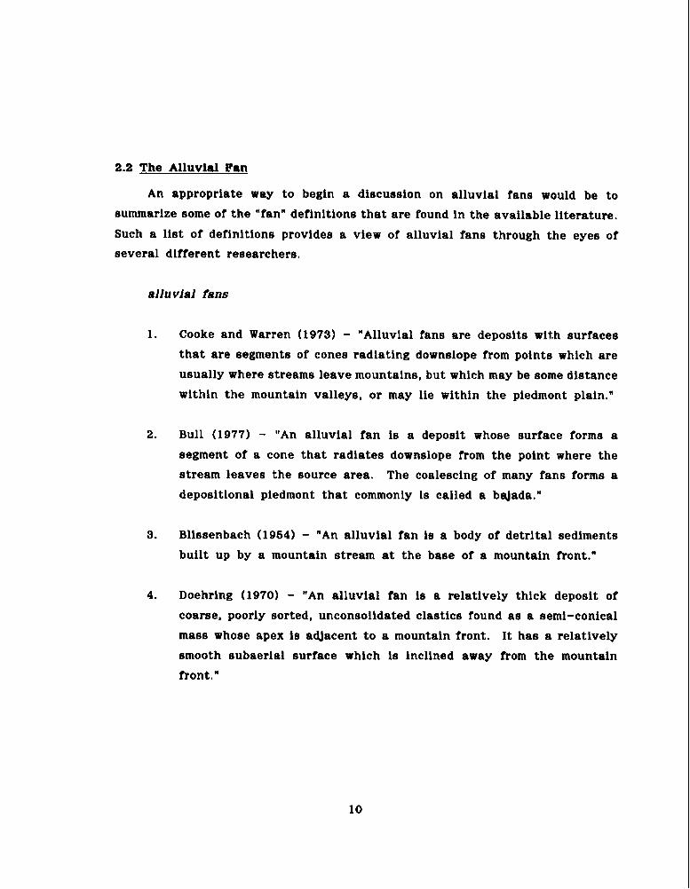
2.2 The Alluvial Fan
An appropriate way to begin a discussion on alluvial fans would be to
summarize some of the "fan" definitions tha t are found in the available literature.
Such a list of definitions provides a view of alluvial fans through the eyes of
several different researchers.
ellu vial fans
1. Cooke and Warren (1973) - "Alluvial fans are deposits with surfaces
tha t are segments of cones radiating downslope from points which are
usually where streams leave mountains, but which may be some distance
within the mountain valleys, or may lie within the piedmont plain."
2. Bull (1977) - "An alluvial fan is a deposit whose surface forms a
segment of a cone tha t radiates downslope from the point where the
stream leaves the source area. The coalescing of many fans forms a
depositlonal piedmont tha t commonly is called a baJada."
3. Blissenbach (1964) - "An alluvial fan is a body of detrital sediments
built up by a mountain stream at the base of a mountain front."
4. Doehring (1970) - "An alluvial fan is a relatively thick deposit of
coarse, poorly sorted, unconsolidated clastics found a s a semi-conical
mass whose apex is adjacent t o a mountain front. I t has a relatively
smooth subaerial surface which is inclined away from the mountain
front."
Although this report focuses on alluvial fan activity in Arizona, it should be noted tha t the existence of alluvial fans is not limited to desert reglons.
Rachockl (1 98 1) states:
"Alluvial fans are found in valleys or in the foot-hills of mountalns
in all latitudes irrespective of cllmatic conditions. They were formed,
and are still being formed, a t the fronts of ice-caps and glaciers, a s
well a s in moderate semi-arid and arid regions."
Cooke and Warren (1973) support this position by statlng:
"Alluvial fans are by no means confined t o hot deserts. They occur
In cold arid areas such a s northern Canada (Leggett. Brown and
Johnston, 1966) and also occasionally in humid areas. But in humld
areas of perennial drainage, streamflow tends to remove the potential
fan debris through the drainage system."
Fans do, however, appear t o be more common in basin-range deserts. A s
reported by Rachocki (19811, Langbeln and Schumm (1968) consider an annual
rainfall ra te of 10 to 14 inches to be a n optimum range for the development of
alluvial fans. Such a low rainfall ra te creates a sparse cover of vegetation
(thus exposing more surface area to erosion), yet still supplies sufficient water
for transporting the eroded material. A s is the case in Arizona, such rainfall
most frequently takes the form of short-duration, high-intensity storms which
produce substantial runoff rates tha t a re capable of transporting large volumes
of sediment and debris.
Until approximately the 1960 era, alluvial fan research has reportedly been
very minimal in relation to other landforms. Rochocki (1981) indlcates tha t
approximately 100 research papers have been dedicated to alluvial Ian processes during the past century. However, Bull (1977) considers these landforms as

being the obJect of intensive study, especially during the las t two decades. The results of the author 's l i terature search would indicate t ha t there has
been an increase in publications on alluvial fans during the pas t 20 t o 30 years.
Some of t h l s increased attention i s undoubtedly attributable t o the urbanization
of fans t h a t began t o occur during this period.
2.2.1 Alluvial Fan Terminology
Prior t o discussing alluvial fan characteristics, it would be beneficial
to define certaln terms which a r e frequently used when analyzing fan processes.
An excellent summary of alluvial fan tarmlnology ie presented by Rochocki
( 198 1). For the reader's convenience, these definitions a r e repeated herein.
In several cases, the definitions a re croes-referenced to a n originator. Not
al l of these terms will be used in the abbreviated discussion presented in
this report.
abandoned channels channels no longer connected t o mountains (Denny, 1967)
abnormal fanhead an inc is ion of the fanhead caused by cl imatic inc is ion changes o r tec tonic movement (looke, 1967)
a l l u v i a l fan see Section 2.1
apex
base
braid bars
the highest point of an a l l u v i a l fan, general ly where the stream emerges from t h e mountains (Drew, 1873)
the term applied t o t he outermost o r lowest zone of t he fan (Blissenbach, 1954)
f l a t gravel and sand bars separat ing several braided channels (Denny, 1965)
braided d i s t r i b u t a r y secondary channels t h a t extend downslope from channels the end of the main stream o r fanhead trench and
a r e characterized by repeated d iv is ion and re jo in ing (Bull, 1964)

cross-fan profile
drainage basin
ephemeral stream
fan bay
f an-bench
fan dissection
fan entrenchment
f anhead
fanhead trench
fan incision
fan mesa
fan segment
a topographical profile of an alluvial fan, roughly parallel to the mountain front (Bull, 1964)
the area above the fan apex that is drained by the mountain stream (Bull, 1964)
a stream, or part of a stream, that flows in direct response to precipitation (Bull, 1964)
the uppermost part of a fan that reaches into the mountain canyon (the term used by Davis, 1938; defined by Blissenbach, 1954)
small scale form of coalescing alluvial fan (the term used by Carter, 1975)
a,general term to include both entrenchment and incision (Wasson, 1977)
downcutting into the fan surface of a channel that is contributing sediment to the fan sur- face. Entrenchment usually occurs during fan construction (Wasson, 1977)
the area of the fan close to the apex (Blissen- bach, 1954)
a stream channel entrenched into the upper, and possibly the middle, parts of a fan (Bull, 1964)
downcutting into the fan surface by a channel that crosses the fan margin. Incision is usually associated with fan destruction (Wasson, 1977)
an alluvial fan remnant left standing in the process of fan degradation (the term used by Eckis, 1928; defined by Blissenbach, 1954)
part of an alluvial fan that is bounded by changes in slope (Bull, 1964)

hanging fan
intermittent stream
intersection point
midf an
normal fanhead trenching
paraglacial alluvial fans
piedmont plain
pseudotelescopic structure
radial line
rock fan
sand-finger fan
a fan formed by the in-filling of a small tributary valley whose surface is continuous with the older, dissected main surface (Lustig, 1965)
a stream, or part of a stream, that flows only occasionally upon receiving water from seasonal sources such as springs, and from bank storage, as well as from precipitation (Bull, 1964)
the point at which the main channel merges with the fan surface (fooke, 1967)
the area between the fanhead and the outer fan margin (Blissenbach, 1954)
the incision produced by changes in slope in the upper reaches of the fan (Eooke, 1967)
fans which are products of an environment in the process of transition from predominantly glacial to predominantly f luvial conditions (Ryder , 1971)
a broad sloping plain formed by the coalescence of many alluvial fans (Bull, 1964) synonyms: piedmont alluvial plain, compound alluvial fan, bajada.
the structure of an alluvial fan created by the slumping of unconsolidated fan deposits (Blissenbach, 1954)
a straight line on the fan's surface extending from the fan apex to the fan toe (Bull, 1954)
an area of bare or thinly covered bedrock at the point where the ravine slope is suddenly reduced (Wyckoff, 1966)
a small form of alluvial fan developed by the flow of water-saturated sands (the term used by Carter, 1975)

secondary alluvial fan
sieve lobes
subsidence cracks
superimposed fan
telescopic structure of an alluvial fan
wadi fan
wash
wet-f an
the alluvial fan at the base of the large primary alluvial fan, which consists mainly of re-worked primary fan deposits (Blissenbach, 1954)
lobate masses of coarse and permeable deposits (looke, 1967)
cracks that develop between an area of near- surface subsidence and an area that remains stable (Bull, 1964)
a fan developed during a secondary stage of deposition. It0 growth is normally initiated by tectonic movements within the mountains that increase slope angles (Blissenbach, 1954)
the structure of an alluvial fan formed by the repeated dissection and in-filling of the pri- mary fan surface (the term applied by Blissen- bach, 1945)
an alluvial fan at the mouth of a wadi; depos- ited during Pleistocene pluvial periods (Glen- nie, 1970)
the action of vigorous branches of the stream cutting deep channels into the fan (Wyckoff, 1966)
the term used by Schumm (1977) to describe large alluvial fans created by streams in mountain foreland areas, and not in semiarid regions
2.2.2 Alluvial Fan Morphology
As can be inferred from the prevlous eectlons of this report, a
mountaln/pialn interface could be consldered a primary prerequisite for the
creation of an alluvial fan (see Figure 2.1). A drainage channel, connecting
the two areas, then becomes the conduit for transporting water, sediment,

and debris from the mountain t o the piedmont plain. The connecting channel is confined to a relatively narrow width whlle
traversing the mountain area. Narrow channel wldths promote highly con-
centrated flow (large unit discharge), whlch in turn creates large sediment
transport rates capable of moving sizeable volumes of sediment. Upon passing
the interface between the mountain mass and piedmont plain, the channel is
no longer confined by canyon walls. Accordingly, the flow is free to spread
laterally, which causes a large decrease in unit discharge and a corresponding
decrease in sediment transport rate. Being no longer able to transport the
sediment/debris load delivered to the terminus of the confined channel,
sediment deposition occurs on the piedmont plain and the birth/growth of an
alluvial fan results. The shape of such fans are characterized by their
resemblance to the segment of a cone.
A s a point of interest, i t should be noted tha t early theories on the
mode of sediment deposition attributed this phenomenon to an abrupt change
of channel slope a s the water passed the mountain/piedmont plain interface.
Bull (1977) attributes this theory to Chamberlain and Salisbury (1909) and
indicates tha t it has, unjustifiably, continued to be published is some literature
sources "despite contradictory arguments and evidence published by Bull
(1964a). Melton (1966). Denny (1966). and Hooke (19721." Bull notes tha t
the slopes on the upper reaches of most fans are very similar to the channel
gradients extending upstream from the fan apex. There is a decrease in
slope in the downstream direction (all fans have concave radial profiles) but
there is no abrupt slope change a t the mountain/piedmont plain interface.
Bull is a strong advocate of the "lose of channel confinement" theory a s the
most probable mechanism triggering the sediment deposition tha t creates the
surface of an alluvial fan.
To illustrate the concavlty of a stream profile on an alluvial fan, the
author plotted a profile for Hieroglyphic Canyon, which has transported
material onto a n alluvial fan along the southwest side of the Superstition

Mountains near Apache Junctlon, Arizona. The resulta of thls lnvestlgation, presented ln Figure 2.2, indicate the existence of a very smooth, concave
proflle extendlng from the mountaln onto the alluvial fan.
Figure 2.2 Profile of Hieroglyphic Canyon Fan
Elevation (f t)
4500 -
Transition From Mountain Canyon To Piedmont
3000 -
m
2500 - Alluvial Fan
2000 - Approximate Toe Of Mountain Mass
1500 - I I I I I I k
0 5000 10000 15000 20000
Distance (ft)
Clearly, there is a subetantlal reduction in elope from the upper end
of the watershed to the toe of the fan. However, thls decrease In slope 1s
gradual, and, even though it wlH create a reduction in sediment transport

capacity, the reduction due to a slope change will undoubtedly be subetantially less than tha t resulting from an abrupt reduction in unit discharge a s channel
flow leaves the confines of a mountain canyon and spreads across a piedmont
plain. The author agrees with Bull's hypothesis tha t a change in channel
geometry is the primary mechanism for sediment deposition on a fan surface;
however, t he gradual slope reduction also has to be considered a s a contributing
cause for this deposition, although to a much lesser extent than the change
In channel geometry.
The morphology of an alluvial fan is dependent upon a complex lnteraction
of several variables. Bull (1968) l ists such factors as: 1) area, lithology,
mean slope, and vegetative cover of the source area; 2) slope of the stream
channel; 3) discharge, climatic, and tectonic environment; and 4) geometry
of the mountain front, adjacent fans and the basin of deposition. The role
of each of these varfables in fan formation is obvious when viewed within
the context tha t a fan is formed by the eroslon and transport of material
from a mountain area onto an adjacent plain. All the listed variables in
the first three categories are directly connected to the eroslon or sediment
transport process. The variables in category number four address physical
constraints tha t place limitations on the available area of deposition. For
example, the geometry of a mountain front might dictate how abruptly a
channel might transition from the conflned geometry of a canyon to the
unconfined environment of the fan surface. The face of a mountain front
might also include irregular outcrops of bedrock t h a t would prevent the flow
of water along an unobstructed 180 degree arc adjacent to the mountain
front. Adjacent alluvlal fans would obviouely reduce the lateral area available
for fan growth. The basin of deposition might terminate along a river.
Base-level changes in the river could induce headcutting or aggradatlon on
the fan surface.
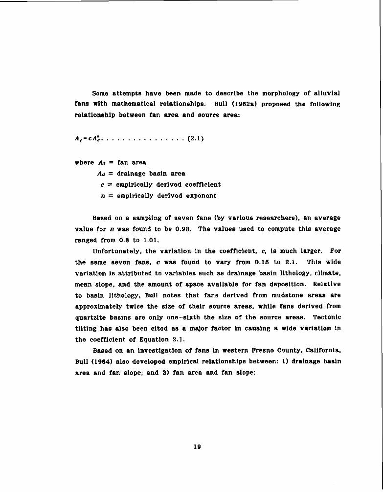
Some attempts have been made to describe the morphology of alluvial fane with mathematical relationships. Bull (1962a) proposed the following
relatlonship between fan area and source area:
where Ar = fan area
Ad = drainage basin area
c = empirically derived coefficient
n = empirically derived exponent
Based on a sampling of seven fans (by various researchers), an average
value for n was found to be 0.93. The values used to compute this average
ranged from 0.8 to 1.01.
Unfortunately, the variation in the coefficient, c, i s much larger. For
the same seven fans, c was found to vary from 0.16 t o 2.1. This wide
variation is attributed to variables such a s drainage basin lithology, climate,
mean slope, and the amount of space available for fan deposition. Relative
to basin lithology, Bull notes tha t fane derived from mudstone areas are
approximately twlce the size of their source areas, while fans derived from
quartzite basins are only one-sixth the size of the source areas. Tectonic
tilting has also been cited a s a major factor In causing a wide variation in
the coefficient of Equation 2.1.
Based on a n investigation of fans in western Fresno County, California,
Bull ( 1964) aleo developed empirical relationshlps between: 1 ) drainage basin
area and fan slope; and 2) fan area and fan elope:

for drainage basins comprised of 48% to 86% mudstone & shale;
and for drainage basins comprised of 68% to 68% sandstone;
where SF = overall fan slope (ft/ft)
AD = drainage basin area (square miles)
AF = fan area (square miles)
The reader should be cautioned t h a t Equations 2.2 through 2.6 were
developed from slte-specific data. Accordingly, the coefficients and exponents
contained in those equations would not necessarily be appropriate for
application t o other sites.
Troeh (1966) presents the theoretical development of a three-dimensional
equation t o describe the surface of a n alluvial fan. Based on the equation
of a right circular cone, and adding a component to reflect the concavity of
the radial fan slope, the following relationship was derived:

where Z = elevatlon at any point on the surface of the cone (fan)
P = elevation a t the central point of the cone (theoretical
fan apex)
S = slope of the fan a t point P
R = the radial dlstance from point P to point Z
L = half the ra te of change of slope along a radial line
The location of point P in Equation 2.6 is found by the projection of
a perpendicular from the tangents to several contour lines on the fan. The
point which most nearly f i ts the intersection of all the perpendiculars is
considered a s point P.
For a given fan, Equation 2.6 i s ultimately reduced to a function of R.
Troeh demonstrates the solution of the equation by writing Equation 2.6 for
three different points on a fan surface, and then performing a simultaneous
solution of three equations containing three unknowns (P. S, and L). Application
of thls procedure (by Troeh) to a pediment near Glla Butte, Arizona produced
excellent agreement with actual landform contours.
2.2.3 Mechanisms of Alluv1.l Fan Deposition
A review of alluvial fan literature indicates tha t fans are formed in
response t o water-laid deposits and debris deposits. A third mechanism,
called a sieve deposit, has also been observed on alluvial fans. Each of these
phenomena are discussed in the following paragraphs.
1 wa ter-laid deposits
Bull (1977) describes water-laid deposits a s "sheets of sediments" tha t
are deposited as surges of sediment-laden water are dispersed across the

fan surface after leaving the confines of a well-defined channel. The sediment/water mixture Is transported across the fan by a dense pattern of
shallow, braided, distributary channels that generally have a depth of flow
ranging from about 4" to 20". A s is characteristic of braided systems, these
shallow channels are prone to rapid sedimentation which causes a diversion
of water to a new flow path or braid.
Rachocki (1981) presents excellent photographic documentation of both
pure sheetflow and shallow braided flow tha t were observed on man-made
alluvial fans created a s part of a gravel pit operation. Rachocki's photographs
illustrate surges of pure sheetflow. occurring near the apex of the fan, which
transltion into a classic braided-flow pattern a s water moves further down
the fan surface.
A second type of water-laid deposit described by Bull refers to the
filling of channels that have been temporarily entrenched into the fan surface.
Although he does not elaborate on this phenomenon, it is assumed tha t he
is referring to larger and more well-defined channels than those associated
with the braided distributary system. These larger channels are also subject
to receiving overloads of sedlment which can cause aggradatlon and subsequent
backfilling. Bull notes tha t the sediment deposits in these larger channels
are coarser-gralned and more poorly sorted than thoee deposited in the
shallow, braided distributary channels. The thickness of these deposlts i s
most frequently found to be between 2" and about 40".
2) debris-flow deposits
The second maor type of fan deposition occurs in response to debrls
flows, which are very viscous, dense mixture8 of water and sedlment. Hooke
(1967) describes debris flows a s quasl-plastic substances which leave deposlts
consisting of cobbles and boulders imbedded in a matrlx of flne material.
Due to the very high viscoelty in debris flows, the eettllng velocity of
individual sediment particles is greatly reduced, thus allowing debris flows

to retain relatively large particles in suspension. Debris flows can be identified in the fleld a s longitudinal lobes or
tongues. In the author's opinlon they have a strong resemblance to fresh
lava flows.
Sharp (19421, a s referenced by Hooke (19671, also describes the probable
formation of bouldery, sharp-crested levees on some alluvial fans a s being
created in response to coarse material being accumulated in front of a debris
flow and subsequently being shoved aside by the advancing debris front,.
Levees formed in this manner tend to confine the remainder of the debris
flow. Hooke also notes tha t some debrls flows may overflow the banks of
an entrenched channel and create levees along the channel banks.
A second category of debris flows has been described by Bull (1977) a s
a "mudflow". A s the name might imply, a mudflow is "a type of debris flow
tha t consists mainly of sand-size and finer material." A s a matter of interest,
Bull notes tha t the term "mudflow" is often used in a generic sense to refer
to all types of debris flows, since mud is a common ingredient in aH such
flows.
3) sieve deposits
Unless the alluvial fan surface is formed with high concentrations of
silts and clays. I t will tend to be relatively permeable. Under such conditions,
water flowing over the fan surface wi l l be subject to large lnfiltratlon losses.
When the infiltration rates are high enough, the entire flow may infiltrate
into the fan surface prior to reachlng the toe of the fan. When this occurs,
the sediment being carried by the water wi l l be deposited at the point where
there is no longer sufficient water to transport the material. This phenomenon
was described and named by Hooke (1967):

"Because water passes through rather than over such deposits, they ac t a s strainers or sieves by permitting water t o pass while
holding back the coarse material in transport. I call the lobate masses thus formed "sieve lobes" or "sieve deposits" and the mode
of formation is sieve deposition."
Hooke glves a very detailed account of t he formation of sieve deposlts
on laboratory fans. He also made a field identification of such deposlts on
several fans in California, and points out t ha t sieve deposlts may be initiated
by the complete infiltration of the transporting water or by a break in fan
slope.
2.2.4 Alluvial Fan Diseection
Depending upon the interaction of the many varlables tha t influence
alluvial fan morphology, the fan surface may exhibit varying degrees of
channel inclsement or dlssection. Such lncisement might take the form of a
major h n h e a d trench, t ha t could extend from the apex to midfan, or i t might
be localized incisement resulting from rain falling directly on the fan surface.
The types of, and possible reasons for, fan dissection are discussed in t he
following paragraphs.
1) fanhead trench
A fanhead trench is connected directly to t he trunk stream feeding the
apex of a fan. The depth and length of these trenches may vary from fan
to fan. Several hypotheses have been presented t o explaln their occurrence.
These include: 1) climatic changes which might cause a substantial disruption
in the amount of sediment being delivered from the mountain area t o t he
fan; 2) tectonic changes which can cause differential movement along the
mountain/alluvlal fan interface (such movement might occur a s the result of
normal mountain building processes or movement along a faultline); and 3)

the occurrence of exceptionally large floods (Denny 1967) which may create sediment transport rates far in excess of the available sedlment supply.
Bull (1977 1 presents a mathematical expression relating tectonic activity
to both the entrenchment and aggradation of alluvial fans. For fan deposition to occur along the mountain front, the following inequality must be maintained:
where A u / A t = the rate of change of tectonic uplift for the mountain
A w / A t = the rate of change of channel downcuttlng In the mountain
A s / A t = the rate of change of fan deposition a t the mountain front
Conversely, when uplift becomes less than channel downcutting in the
mountain area, channel entrenchment wlll tend to extend onto the fan surface
and move the loci of depositlon downslope from the fan apex. Under such
conditions, the fan head is bypassed as an area of deposition and will become
prone to localized eroslonal processes. Bull defines this condition with the
following lnequallty.
where A u / A t , and A w / A t
are a s defined for Equation (2.7) and
A e l A t is the ra te of erosion of the fan deposlts adjacent t o the mountain.

Denny (1967) presents a hypothetlcal case where local gullying on the abandoned upper segments ( tha t have been bypassed by a fanhead trench) of the fan may cut deeper into the fan surface than the adjacent fanhead
trench. This creates a condition where bank erosion of the fanhead trench
may cut through to a local gully and allow the gully to capture the flow of
the fanhead trench. This phenomenon, which is called channel "piracy", will
shift the loci of deposition to a new point on the fan. Channel piracy is
an important mechanism in the development of an alluvial fan.
Channel entrenchment can provide both lateral movement of sediment
deposition across the width of fan a s well a s lengthwise along a radial line
extending from the fan apex to the toe. Lateral movement can be caused
by channel piracy or through channel avulsions tha t might be created by
plugs of mudflow or debris flow. Such lateral shifting might also occur a s
a simple function of one part of the fan being raised sufficiently higher than
an adjacent part, thus creating the potential for a steeper gradlent of flow
towards the lower area.
Deposition along a radial line can occur in response to an imbalance
between sediment transport rate and supply. This phenomenon can move the
location of the intersection point (point at which the invert of the entrenched
channel intersects or merges with the fan surface) up and down a radial
line, thus allowing sediment to be deposited either closer to, or farther from,
the fan apex. For example, a n excess of sedlment (beyond the existing
transport capacity) would cause deposition in the channel and a subsequent
retreat of the intersection point towards the fan apex. Conversely, should
exlstlng transport capacity exceed the sedlment supply, the channel bed
would tend to degrade and advance the intersection point towards the fan
toe.
Based on observations of laboratory fans, Hooke (1967) relates the
following description relative to the movement of the intersection point:

"The intersection point on laboratory fans is commonly near midfan. This appears to be because fluvlal deposition predomlnates near
the toe and occurs without downfan migratlon of the intersection
point, while overbank debris flow deposition predominates near the
fanhead. Thus the average radial position of the intersection point
should be related t o the relative importance of debris flows and
fluvial procesees In transporting material to a fan.
The intersection point on laboratory fans shifted gradually due
to debris-flow and fluvial deposition. The intersection point would
mlgrate up-fan a s low banks of the main channel were buried. Subsequent water flows then eroded a new channel offset laterally
from the previous course."
Bull (1977) provides the following account of radial deposltlon:
"Migration of the depositional area along a given radial line occurs
a s a result of entrenchment or backfilling of the stream-channel
extending from the source area. Fanhead trenches commonly extend
half the length of the fan. Some streams are permanently entrenched, and may have channel bottoms tha t are a s much as 60 meters
below a fan surface with an old a011 proflle. Other fanhead trenches
appear to be temporary, being less than 16 meters below a fan
surface having no visible soil profile; and having been entrenched
and backfilled one or more times before the present channel
downcutting."
2) dissection not related to fanhead trenching Channels or gullies on a fan can also occur without being connected to
a fanhead trench. A s mentioned in the previous paragraphs, fanhead trenchlng can cause sediment deposition to bypass the fanhead area near the apex.

Being deprived a supply of new eedlment Prom the mountaln area, these bypassed fanhead areas wil l begin to erode and create a local dralnage
network to dispoee of precipitation falling directly on the fan surface.
A change in base level along the toe of a fan can also initiate dissection
of a fan surface or accelerate (deepen) exlsting dlssection. A common example of thls type of base level change occurs when a stream is flowing along the
toe of a fan. The location of such a stream can cause fan dissection in two
ways. The flrst way would accompany a long-term lowering of the base-flow
in the stream or an actual lowering of the streambed. Such a condition
would create a steep elope from the fan toe to the streambed. Water flowing over such a precipice would cause headcutting back into the fan surhce.
The second method would accompany a swing in the stream-flow alignment
either into or away from the toe of the fan. A s the stream swings into the
fan, the toe would be undercut, causing a sharp drop-off (as described
previously) from the fan surface to the streambed. Conversely, as the stream
alignment migrates away from the fan toe, a n aggradational tendency wi l l be
induced (Blissenbach 1954).
Bull (1964) presents an interesting statistic on the location of fanhead
channels relative to a medial position, which is defined as a radial line projected perpendicular to the apex a t the mountain front. This definition
assumes that water has the freedom to flow through a 180 degree arc upon
passing the mountain front. Based on a sample of 76 fans in California, two
thirds of the fanhead channels were found to be located within 30 degrees
of the medial line. Only three channels were found to have a deviation of
more than 60 degrees from the medial position. Bull concludes tha t the large
concentration of channels within a 30 degree arc on either side of the medial
line implies tha t this central segment of the fan is prone to receiving more
deposition than those areas nearer the lateral edges of the fan. This is

consistent with the general shape of a fan, which is a cone-shaped landform
with a convex cross-profile. Such a profile has a maximum depth at the
center of the cone.

2.3 Pediments
Although this report is directed towards a discussion of engineering problems
associated with the development of alluvial fans, an encounter with a pediment
may be a more common occurrence for development in Arizona. Accordingly, a very brief discussion of pediment characteristics is provided to alert the reader
to the existence of these two different landforms.
A review of current literature reveals considerable differences of opinlon
on the formation of pediments, and even the definition of a pediment. Several definitions obtained from available literature are summarized as follows:
pediments
1. Cooke and Warren (1973, page 196) - "In most cases, the pediment 1s
a complex surface, comprising patches of bedrock and alluvium, in
places capped by weathering and soil profiles, punctuated by inselbergs,
and scored by a network of drainage channels."
2. Bull (1977) - "In trying t o distinguish an alluvlal fan from a pediment
in the field, it is useful to remember that alluvial fans are formed in a depositional environment and tha t pediments are formed in an
erosional environment. Many pedimented areas have a large number
of streams and rills t h a t drain to the piedmont, but an alluvial-fan
piedmont has fewer streams each acting as a major conduit for water
and sediment tha t is transported to the fanhead. Bedrock knobs rarely
protrude through the alluvium of fans but a re typical of pedimented terrains, where a veneer of alluvium and colluvium mantles bevelled
bedrock. ............ A s a general guideline, fans may be dlstinguiahed
from pediments a s being landforms where the thickness of deposits is
more than 1/100 the length of the landform."

Bull goes on to s ta te tha t the continued lack of tectonic uplift (along the mountain front) will change the depositional environment of a n
alluvlal fan to an eroslonal environment where pedimentation is the
main process operatlng on the landscape (see Equations 2.7 and 2.8).
He attributes the scarcity of earthquakes In south-central Arizona
a s a prominent factor for the abundance of pedimented landscapes
which are typical of this area.
3. Doehring (1970) - "The term pediment, a s used herein, refers to a
low gradient, subplanor, topographic surface located at the foot of a
mountain mass in an arid or semiarid, mid- t o low-latltude desert
region and which meets the mountaln front a t an angular junction.
Pediments are underlain by consolidated rock, do not follow lithologic
or structural anisotropies or inhomogeneities, are ueually fan-shaped
in plan, and may have an alluvlal veneer not exceeding 60 it. in
thickness."
4. Hadley (1967) - "Pediments are erosional surfaces of low rellef, partly
covered by a veneer of alluvium, that slope away from the base of
mountain masses or escarpments in arid and semiarid environments."
A s with alluvial fans, pediments most frequently occur between a mountain
front and an alluvial plain. However, unlike alluvial fans, pediments may not
always be part of a clearly deflned drainage system. The surface of a pediment
often occurs in more than one drainage system and it may be impossible to
assume tha t present drainage networks on a pediment were associated with its
formation (Cooke and Warren, 1973).
Due to similarities in their locations along a mountain front, and in some
cases their similarity In shape to a segment of a cone (Hadley 1967, presents
a topographic mag of a pediment which has a very distinct fan shape), it can

be difficult to differentiate between a pediment and a fan without extensive field investigations. Hadley notes that most pediments exhibit an irregular plan
view. with the irregularities more pronounced where the pediment intersects
rock surfaces with varying resistance to erosion. Some researchers (Gilluly, Johnson, and Rich) also present field data that describe pediments as widening
from a canyon mouth to the downstream end.
From a distance, pediments have been described as having a relatively smooth surface. However, close examination of the surface wi l l usually reveal an intricate pattern of dlssection. Gilluly (1937) (as referenced by Hadley,
1967) describes a pediment on the AJo quadrangle of Arizona as having dissected drainage channels approximately 40 feet deep near the head of the pedlment.
The channels were noted to decrease in depth in the downstream direction.
Based on an analysis of topographic maps, Doehring (1970) reports that:
"the drainage texture (spacing of low order drainage channels) tends to become
flner in a headward direction on pediments but remains relatively constant on
alluvial fans." Doehring's paper presents a methodology, called the "texture
curve methodH to identify the drainage texture of landforms from topographic maps.
Relative to surface deposits, Hadley (1967) indicates that pediments have
been described a s having from no alluvial cover to over 100 feet of gravel and
fine-grained alluvium veneer. Causes for this variation in thickness are
attributed to base-level changes, stream discharge from the mountains, and
climatic changes. Hadley aleo references an interesting suggestion by Tator
(1962) that the thickness of pediment alluvium often averages about the depth
of effective stream scour.
Although there is no consensus of opinion regarding the process of pediment formation, Hadley (1967) notes that two processes are generally recognized at3
the most probable cause of pedimentation: 1) lateral planation by streams; and
2) weathering and removal of debris by rill wash and unconcentrated flow. The theory of pediment formation by planation (reduction of a land area

by erosion to a nearly fa t surface, Webster's New World Dictionary, 1984) assumes that stream-flow emanatlng from the mountains wlll continually migrate back and forth across the pedlment surface and gradually wear it down by erosion.
Obviously, thls theory apparently makes the assumption tha t sediment deposition
is not a promlnent process on a pediment surface. Hadley (1967) in referencing the planation theory to one of its strong proponents (Douglas Johnson) summarize6 Johnson's comments:
"...pediments, or rock planes, as he called them, are the product of
normal stream erosion. Pediments ("rock planes") result from the fact
tha t the heavily laden streams of arid regions are not able to cut
vertically; they therefore tend to migrate laterally."
The second theory (weathering and rill wash) assumes that material wi l l
be weathered from the mountain front and removed by rill wash, unconcentrated
flow, or stream actlon. - As noted In the preceding paragraph, this theory must also assume that the weathered material will be transported across the pedlment
rather than being deposited upon it.
In comparing these two theories, many researchers feel tha t pediment
formation may be a cornblnation of both processes, although Hadley (1967)
indicate6 that the theory of weatherlng and rill wash seems to be the more
widely accepted of the two scenarios.
After reviewing several technical papers on alluvial fans and pediments,
the author is left with the definite impression that a major difference between pediments and alluvial fans is tha t fans are a depositional landform whlle
pediments are an erosional landform. It is interesting to note tha t Bull (1977) indicates tha t a contlnued lack of tectonic uplift may transform an alluvial fan
into a pediment environment. This 1s in concert with the predictions of Equations
2.7 and 2.8, which relate the rate8 of change of tectonic uplift to channel
downcutting, fan deposition, and fan erosion. In other words, a fan wlll tend

to transition into a pedlment envlronment when the erosional forces dominate over the depositlonal forces.
Due to the lack of depositional tendencies on a pediment, it would appear
tha t they might be a more stable environment (from a drainage perspective)
than a fan. In the absence of large debris flows, and general sediment deposition,
pediments should not be prone t o abrupt channel shifting during flood events.
Although Denny (1967) indicates t h a t channel piracy may st i l l occur on pediments,
he also s ta tes t h a t many of t he gullies on pediments a r e eroded into the rocks
of the mountaln block.
Relative t o drainage issues, Cooke and Warren (1973) present an excellent
summary of t he topography of a pedlment. Excerpts from their description a re
quoted a s follows:
"Although many published accounts may give a contrary impression,
a pediment which 1s a clean, smooth bedrock surface i s rare indeed.
In most cases, the pediment is a complex surface, comprising patches
of bedrock and alluvium, in places capped by weathering and soil
profiles, punctuated by inselbergs, and scored by a network of drainage
channels. . .. . . . . Another important ye t neglected feature is the presence of cut-and-fill
features on pediments. Channels 1-3 meters deep and now filled with
alluvium have been described .... (by various researchers). The presence
of burled channels indicates t ha t the relations between erosion and
sedimentation in t he pedlment zone have changed during the period
of pediment development, probably as a consequence of changed
environmental circumstances. The filling of channels and other
depressions in bedrock by alluvium is commonly responsible for t he
general smoothness of many pediments.
Closely related to buried channels a re pediment drainage nets. These.
too. have rarely been considered. There are three common types. (i)

Channels occurring in the upper part of the piedmont plain, which commonly form a distributary system and die out lower down the
surface. Such channels often straddle the piedmont angle, [piedmont
angle is the angle produced by the intersection of the lines representing the slope of the mountain h n t and the slope of the piedmont plain
(Cooke & Warren, 1973)l and they are deepest a t intermediate positions on their longitudinal profiles. (ii) Channels occurring on the lower
part of the piedmont piain, which are generally deepest a t the lowest
point in their longitudinal profiles, and usually form part of a drainage
system tha t has been rejuvenated on one or more occasions by lowering of base-level. Such systems may cover the whole pediment. When
drainage in this type of net is rejuvenated it often leads to the
destruction of the pediment surface. (iii) On relatively undissected
surfaces, often between areas characterized by types (i) and (ii),
drainage nets may consist of complex and frequently changing patterns
of shallow rills. These drainage nets are similar in pattern and location to those on
alluvial fans, and they may perhaps be explained in similar terms. Type (i) is probably generated by drainage in the catchment area
behind the pedlment, type (ii) may result from runoff on the pediment surface itself, and type (iii) probably arlses from rillflow, perhaps
characteristic of declining sheetfloods, in the intermediate zone. Drainage incision may reflect adjustments to climatic or tectonic
changes, or changes in the nature of waterflow withln the system.
Such changes could have accompanied pediment formation, or they
could be younger and lead to pediment destruction".

3 NATIONAL FLOOD INSURANCE PROGRAM ACTIVITY IN ARIZONA
One of the principal objectives of this study is to examine the application of
NFIP criteria to floodplain management, especially on alluvial fans. and to evaluate
ADOT procedures for coordlnating the plannlng and design of highway projects In
floodplain environments with the Federal Emergency Management Agency (FEMA).
The following subsections of thls report address these issues a t the federal,
s tate , local, and ADOT level.

3.1 Federal Prognm
A s indicated previously, Congress passed the National Flood Insurance Act
in 1968. This Act created the National Flood Insurance Program (NFIP) which
was designed to reduce future flood losses through local floodplain management
efforts and to transfer the costs of residual flood losses from the general
taxpayer t o the floodplain occupant.
An integral part of this program was the development of flood risk studies
to provide data for local floodplain management and t o establish actuarlal
insurance rates.
Based on an estimate of projected property-at-risk, FEMA routinely employs
different levels of detail when preparing these risk studies (FIS/FEMA,1984).
Three levels of study detail are defined as:
detailed flood insurance study
limited detail flood insurance study
* existing da ta study
The level of study detail in these three categories ranges from the preparation
of very detailed Flood Insurance Rate Maps (FIRM) to simple approximations of
floodplain limits based on existing technical data or historic floods.
Communities participating In the NFIP are required to use these studies
and floodplain maps and to enact certain floodplain management measures (in
accordance with the amount and nature of flood risk da ta provided by FEMA)
to regulate new floodplain construction in order to reduce future flood damage.
The policies and management criteria embodied by the NFIP are listed in
44 CFR (Code of Federal Regulations), Parts 69 through 77, dated October 1,
1986 (see Federal Emergency Management Agency, 10/1/86). Thls document does
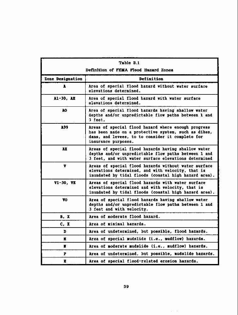
not specifically make reference to alluvial fan flooding. However, several special
flood, mudslide, and flood-related erosion hazard zones are defined. These zones

are defined in Table 3.1
In order to provide technical guidelines for engineers who are retained to
prepare Flood Insurance Studies (PIS) as part of the NFIP, FEMA has published
a document entitled "Guideilnes and Specificatlons for Study Contractors",
September 1986. Appendix 6 of tha t document outlines a specific procedure for
preparing Flood Insurance Studies on alluvial fans. I t also s t a t e s tha t Special Flood Hazard Areas on alluvial fans are to be identified a s Zone AO, which is
further deflned a s follows:
"Zone A 0 is the flood lnsurance ra te zone t h a t corresponds to the areas
of 100-year shallow flooding (usually sheet flow on sloping terrain) where
average depths are between 1 and 3 feet. Average whole-foot depths derived
from the detailed hydraulic analyses are shown withln this z ~ n e . "
Accordingly, this review of federal flood control programs indicates tha t
efforts have been made to address the unlque flooding problems on alluvial
fans. Discussions on details of the technical procedures will be presented in
subsequent eections of this report.
to to consider it complete for

3.2 State Program
Floodplain management a t the State level encompasses several areas of
responsibility. By approval of Executive Order No. 77-6 on September 27, 1977,
Governor Raul Castro directed each State agency t o take the necessary action
to support the goals of the NFIP. Brief discussions of the State's responsibility and programs are presented in the following subparagraphs.
3.2.1 State-Owned Lands
Under NFIP criteria, a State is considered a "community" and muet comply
with the minimum floodplain management criteria se t forth in 44 CFR, Part
60, a s a condition to the purchase of a Standard Flood Insurance Policy for a State-owned structure or its contents.
Discussions with the Arizona State Land Department (ASLD) reveals tha t
State-owned lands located within delineated floodplains are carefully reviewed
to insure tha t any proposed development on such lands is done in accordance
with the criteria established by the NFIP. Representatives from ASLD indicate tha t they routinely send floodplain development plans to the Arlzona
Department of Water Resources (ADWR) for review, and also coordinate such
plans with the floodplain managers of the local juriediction within which the property is located.
3.2.2 State Flood Control Assi8tsnce Program
The Arizona State Legislature enacted several programs during the 1970's
to promote the planning and installation of flood control projects. Since these programs do not specifically address alluvial fan problems, only a brief
discussion wil l be presented for each program.
The Flood Control Assistance Program, which was created in 1973,
authorized the State of Arizona t o reimburse local sponsors for 60% of the
cost of local expenditures for right-of-way, utility, and road relocation work
required for federally approved flood control projects.

Two additional assistance programs were adopted by the State Legislature In 1978. These programs authorized county flood control districts to request the Arizona Department of Water Resources (ADWR) to conduct engineerlng
studies and to develop plans to control specific flooding problems within the
districts. To complement this planning program, the Legislature simultaneously
enacted a financial assistance program which allows the State to fund 60%
of the lnstallation cost of any flood control plan found to be economically
Justified a s a result a completed State sponsored planning study.
A fourth program, approved by the Legislature in 1979, authorized the
State to provide low-interest loans t o county flood control districts for up
to 26% (not to exceed two and one-half million dollars) of the installation
cost of a flood control project developed under the State flood control planning
program.
3.2.3 State Coordinating Agencv
The State program tha t is perhaps most closely associated wlth the
implementation of the NFIP in Arizona is the State Coordinating Agency (SCA).
FEMA encourages (44 CFR, paragraph 60.26) s ta tes to demonstrate a commitment
to the minimum floodplain management criteria se t forth in the NFIP by
designating an agency of s t a t e government t o be responsible for coordinating
the Program aspect8 of floodplain management in the s tate .
A t the present time, ADWR has been designated a s Arizona's State
Coordinating Agency. The NFIP l ists 12 duties and responsibilities tha t the
SCA should maintain a capability to perform (following duties are paraphrased
per Bond, ADWR, 1982):
1. Enact enabling legislation in floodplain management.
2. Encourage and assis t communities in qualifying for participation
in the NFIP.
3. Assist communitles in the adoption of ordinances.

Provide cornmunitlee and the public wlth information on floodplain management.
Ass is t communities in disseminating elevation requirements for
flood- prone areas.
Assist In the delineation of flood-prone areas.
Recommend priorities for Federal floodplain management activities
within the State.
Notify t he FIA (Federal Insurance Administrator) of community
h i l u r e s In floodplain management.
Establish State floodplain management standards.
Assure coordination and consistency of floodplain management
activities with other agencies.
Ass i s t in the identification and implementation of flood hazard
mitigation recommendations.
Participate in floodplain management training activltles.
Due t o limited staff capability, ADWR has been unable t o fulfill 100%
of these obligations, but for t he most part, ADWR has been very effective
as the SCA in promoting the goals of the NFIP in Arizona.
To summarize th i s overview of s t a t e floodplain and flood control policies,
it can be concluded t h a t the S ta te of Arizona has been very active in the
last 16 years in developing programs to mitigate potential flood damage and
to support t h e goals of t he NFIP. However, none of t he State programs have
published official policies dealing specifically wlth alluvial fan flooding.

3.8 Local Pmgrunn
The NFIP provides local communitles with a very comprehensive set of
floodplain management criteria and a s e t of floodplain maps which delineate
specific hazard areas. In Arlzona, these criteria have presently (October 16,
1987) been implemented by 87 communities, cities, and countles.
The NFIP criteria Is intended to be applied to all delineated flood prone
areas, including alluvial fans. FEMA representatives in Region 9 were asked
t o provide a llst of alluvial fans in Arizona for which floodplain dellneations
had been prepared. Access to such information would provide a n excellent data
base to locate communities tha t are attempting to regulate development on
alluvial fans. Unfortunately, FEMA was unable to provide this Information.
A s a parallel effort to acquire input on how communltles are attempting
to use NFIP criteria to manage development on alluvial fans, a questionnaire
was developed which presented specific questions on management policies,
technical procedures, flood damages, and research needs for the alluvial fan
environment. This questionnaire was sent t o every county engineer/flood control
district in Arizona, as well as to all major towns and cities t h a t were thought
t o have possible contact with alluvial fan problems. Questionnaires were also
distributed to ADOT, ADWR and several private consultants who were known t o
have had previous exposure to engineering problems on alluvial fans. A total
of 49 copies of the questionnaire were circulated for input to this report. All
local agencies tha t received the questionnaire had adopted floodplain regulations
tha t met minimum NFIP criteria. Said agencles were also participating in the
Regular Phase of the NFIP.
Unfortunately, the response to the questionnaire was very limited. Replies
were only received from 16 local (non-state) agencies. I t is the opinion of t h e
author tha t this low response is due to the fact t h a t the majority of the local
agencles do not presently have development occurring on a true alluvial fan.
A s a result, they are not faced with the potential devastation tha t has historically

been experienced on some of the classic alluvial fans in California (Palm Desert and Rancho Mirage). The author has been exclusively involved In flood control
engineering in Arizona for the last 14 years. During t h a t period he has not
witnessed, or read reports of, flood damage on a classic, active alluvial fan
t h a t is similar to those referenced for California.
The absence of development on active alluvial fans in Arizona is supported
by the responses on the questionnaires. With the exception of t h e Pima County
Department of Transportation and Flood Control District, no local agencies have
adopted any special floodplain policies to regulate development on alluvfal fans.
The policies adopted by Pima County are discussed in Section 8.2 of th i s report.

3.4 ADOT and t h e NPXP
The impact of the NFIP on ADOT'S responsibilities for highway planning
and engineering can be discussed wtthin the context of two programs:
Federal-Aid Highway Program
Non-Federal Highway Program
Highways tha t are planned and constructed with federal funds must comply
with formal procedures established by the Federal Highway Administration (FHWA)
t o insure tha t such projects are consistent with the etandards of the NFIP.
There is no formal requirement to comply with these FHWA procedures on
non-federally funded highway projects. The following subsections present a
brief discussion of each program.
3.4.1 Federal-Aid Aighway Program
The Federal-Aid Hlghway Program Manual, (November 16, 1979) Volume
6, Chapter 7 , Section 3, Subsection 2, (FHPM 6-7-3-2) prescribes policies
and procedures for the location and hydraulic design of highway encroachments
in floodplains. The policies of this manual are stated as followe:
1. to encourage a broad and unified effort t o prevent uneconomic,
hazardous or incompatible uee and development of the Nation's
flood plalns,
2. to avoid longitudinal encroachments, where practicable,
3. to avoid significant encroachments, where practicable,
4. to minimize impacts of highway agency actions which adversely
affect base floodplains,
6. to restore and preserve the natural and beneficial floodplain values
t h a t are adversely impacted by highway agency actions,
6. to avoid support of incompatible floodplain development,

7. to be conslstent with the intent of the Standards and Criteria of the National Flood Insurance Program, where appropriate, and
8. to incorporate "A Unified National Program for Floodplain Man-
agement" of the Water Reeources Councll into FHWA procedures.
Implementatlon of these policies requires the preparation of a "Location
Hydraulic Studym, whlch includes the following requirement:
"Local, State, and Federal water resources and floodplain man-
agement agencies should be consulted to determine if the proposed
highway action is consistent with existing watershed and floodplain
management programs and t o obtain current information on
development and proposed actions in the affected watersheds."
Accordingly, there is no question t h a t the Federal-Aid Highway Program
places a strong emphasis on coordinating highway projects with all the agencies
tha t might be impacted by such a project.
FHPM 6-7-3-2 also lncludes a section on Design Standards. Although
these standards do not reference or include any special procedures to be
used for alluvial fan locations, they also do not prescribe any specific
technical methodology (i.e., HEC-1, HEC-2, etc.) t ha t has to be used for the
analysis and design of any highway project. Accordingly, the design engineer
is free to exercise his best judgement in selecting a technical methodology
that is most appropriate for a specific highway project. This gives the
engineer ample latitude t o vary his hydrologic/hydraulic design procedures
to accommodate the change in flooding characteristics tha t might be
encountered a s a proposed highway alignment moves from a claesic riverine
environment onto an alluvial fan environment.
In 1982. the FHWA published a document entltled "Procedures for

Coordinating Highway Encroachments on Floodplains with the Federal Man- agement Agency". Essentially, this publication supplements FHPM 6-7-3-2
by providing specific guidance on how hlghway project encroachments into
floodplains and floodways are to be analyzed and coordinated with FEMA and local agencies in order to comply with NFIP criteria. Thls publication has been officially endorsed by FEMA (June 7, 1982) a s providing ".... . an excellent guideline for coordination between highway agencies, communities participating
in the National Flood Insurance Program (NFIP) and FEMA, when flood piain encroachments involving hlghway construction are proposed".
In reviewing the floodplain policies established for Federal-Aid Highway Program prefects, it is very clear tha t considerable emphasis has been placed
and encour- coordination with
all federal, s tate , and local agencies that might be impacted by such a project. From a technical engineering perspective, the prescribed procedures include
flexibillty tha t allows the engineer to select an analysis technique that he
would consider to be most appropriate for the s i te under investigation (e.g.,
riverine or alluvial fan environment). A s long as ADOT continues to comply
with these policies, they will have a sound and effective basis from which
to initiate planning and design etudies for hlghway projects located in a
floodplain environment.
3.4.2 Non-Federal- Aid Highway Program
Highway projects constructed in Arizona without financial assistance
from the FHWA are not dutifblly bound to comply with the procedures outlined in FHPM 6-7-3-2. However, a s a practical matter, these federal procedu-
res/guidelines present a very logical approach to the planning and construction of any highway system in a floodplain environment.
Recognizing the logic of th is approach, ADOT personnel indicate tha t
for non-federal-aid hlghway projects they make every effort to comply with
NFIP criteria and employ a "good neighbor" philosophy in coordinating highway

floodplain encroachments with local agencies t h a t might be lmpacted by such projects. A s with the Federal-Aid Highway Program, ADOT has no specific
pollcy or engineering techniques for application t o highway design on alluvial
fans versus a riverine environment. They maintain the same flexibllity provided in t he federal program, i.e., the highway planners and engineers
a re free to select t he most appropriate design methodology for t he s i te under investigation. This is a common-sense approach t h a t does not bind the
engineer to one specific methodology t h a t may only be applicable to limited environments.
ADOT presently employs what could be termed a "three-phase" process in the planning and design of highway projects. The f i rs t phase in this
process is the preparation of a "Project Assessmentn which identifies the
project objectives and locates one or more alternative highway alignments.
Since th i s report is reviewed by the ADOT Drainage Section, a qualitative
assessment can be made of any potential floodplain/drainage problems tha t
might accompany any of the preliminary alignments. This review can be used a s Justification for elimlnating those alignment alternatives t h a t would be
expected to produce very severe floodplain encroachments or drainage problems.
The second phase consists of a "Design Concept Report" which defines
specific design crlteria and includes a relatlvely in-depth analysis of maJor
drainage problems, such as those t h a t might be encountered on a n alluvial
fan or in a riverine floodplain. A site-specific methodology is employed at
thls phase to: 1) quantif'y the severity and extent of the flooding problems;
and 2) develop a plan tha t could be used to effectlvely eliminate these
problems from being a potential source of danger to t he proposed highway
project. I t is in t h i s phase t h a t t h e engineer h a s the flexibility of selecting a n analytical technique tha t would most accurately simulate t he floodplain
characteristics of t he location under investigation.
Phase three of this procese is "Final Design". A t th l s point a11 major
floodplain/drainage problems should already be resolved. The only remaining

task is to transfer the drainage plan into a set of construction drawings.
In summary, this three-phase highway planning process appears to be
a practical approach to the design of non-federal-aid highway projects. I t
acknowledges the importance of complying with NFIP criteria and coordinating
floodplain encroachments with local agencies. There a re also no rigid policies
which restrict the highway engineer from exercising good engineering judgement
in selecting analytical techniques tha t are most suited for a speciflc project.
If the engineer has an understanding of the baslc fluvial processes associated
with a specific site, he should have no problem working wlthin the framework
of either the federal or non-federal-aid program in developing a reasonable
analysis of t he floodplain problems associated with the s i te .

4 ROAD DAMAGE AND MAINTENANCE COSTS ON ALLUVIAL FANS
From a transportation system perspective, an important product of alluvial
fan research would be to identify speciflc roadway problems tha t have historically
been experienced on alluvial fans and to tabulate the cost associated with repairing such damage and/or implementing unique maintenance procedures to keep the system
operational. In an attempt to gather such information, questionnaires were sent
to the four ADOT District Engineers, all county highway departments, and several
Arizona municipalities. The questionnaire requested information relative to: 1 )
the type of problem encountered; 2) t he estimated annual maintenance cost to
mitigate the problem; and 3) any maintenance program changes tha t have been
implemented to eliminate or reduce damages to roadway systems on alluvial fans.
Unfortunately, a very limited response was received on this topic. This could
be interpreted to mean tha t roadway damage on alluvial fans is very limited in
Arizona, or tha t records are not kept to allow an agency to differentiate between
alluvial fan and non-alluvial fan roadway problems. The following subsection summarlzes the comments tha t were received for various components of a highway
system.

4.1 Hiphray System Damage Categories
The following paragraphs pertain to comments received for the categories
of roads, brldges, culverts, and grade crossinge.
Roads
This category only pertains to the roadway surface/embankment. Comments received for this category of damage are summarlzed as follows:
Washed-out roads
* Erosion of granite mulch backslopes
Erosion and sedimentation
Edge scouring and sediment deposltion
* Rutting and erosion
Roadways become channels when aligned parallel to fan drainage
patterns.
The Clty of Tucson es+,lmated an annual maintenance cost of $26,000 for th is category of roadway damage, while Greenlee County estimated on annual
cost of $300,000 for 369 miles of roadway. No maintenance cost data was received from any other agencies.
Bridges
No damage/maintenance data w a s received for this category other than a general comment of "erosion, scour and sedimentation".

Culverts
Comments received for this category are summarized a s follows:
Constricted openings create upstream watercourse aggradation.
* Reduced flow capacity due to sediment/debris deposition withln the culvert and at the culvert inlet.
Wash-outs and structural damage.
The City of Tucson estimates an annual maintenance cost of $76,000 for alluvial fan culvert installations, while Greenlee County estimates $30,000 per
year for maintalnlng culverts dispersed through 337 miles of dlrt roads. No
annual maintenance cost data was received from any other agencies.
Grade (Dip) Crossings
Comments received for this category are summarized as follows:
Sediment/debris deposition
Standing water which renders the crossing impassable.
Damage t o asphalt paving.
Scouring at pavement edge.
The C i t y of Tucson estimates a n annual cost of $20,000 t o maintaln grade
crossings in alluvial fan areas, while Greenlee County estimates an annual cost
of $16,000. No annual maintenance cost data was received from any other agencies. I

4.2 General Comments/Recommendatlon~
In a n attempt to reduce or eliminate the problems presented in the preceding
section, some agencies indicated the following actions were being pursued:
Eliminate grade (dip) crossings.
Design structures with more emphasis on erosion potential, i.e., cutoff walls and bank protectlon.
Curb and gutter installations requlred along roads.
On a case by case basis, flood control lmprovements may be required
In conjunction with the road construction.
Minor re-alignment of washes.
General improvement in the overall quality of maintenance work.
Closer control being exercised in the deeign and construction
of roadway crowns, dralnage channels, and berme.
Install flood warning signs a t grade crossings.
The type of roadway design and expected rnalntenance effort for alluvial fan envlronments should obviously reflect the level of service required for the
area. For example, is the alluvial fan segment of the roadway part of the
Interstate Highway system, or is it merely to provide local access for very sparse
development. Perhaps one of the key deelgn criterla might be whether the
roadway could tolerate temporary cloeures during flooding conditions. If so,

grade crossings mlght be a preferable alternative to culvert/bridge installations.
For those cases of roadway design tha t involve low traffic volumes to
sparsely inhabited areas, some interesting data is avallable from an article
entltled "Alluvial Fans and Desert Roads - A Problem in Applied Geomorphology:
by Asher P . Schick. This article documents recorded flood damage to roadways
on alluvlal fans in southern Israel. The data derlved from this study were
summarlzed by Schick a s follows:
"(1) The road surface should stick to the original fan surface a s closely
as possible. Available evidence indicates tha t exposure to flood
damage increases with vertical deviation of the road structures from
the grade line.
(2) Sediment settling basins are ineffectual on arld alluvlal fans. E'or
all but insignificant flows, they are filled with sediment during the
first minutes or even seconds of a flood. To make them effective,
they must at tain a capacity of a t least one tenth of the total volume
of some typical flood event. In the examples cited for the event of
12/2/72. this means 6-20 times larger settling basins than those tha t
were in existence at tha t time. Big holes like tha t are difficult to
dig, have to be re-excavated periodically, and mlght incur the wrath
of nature lovers.
(3) In al l cases examined in the framework of the project, bridgeless
crossings were preferable to culverts. The crossings are, on the whole,
less expensive, and entail a much smaller overall deviation from the
grade surface of the fan. Further, i t 1s possible t o design them
carefully in such a way t h a t they wi l l be (i) on the trace of the most
probable flow llnee; (ii) a t a right angle t o these flow lines; and (iil)
vertically positioned slightly below the grade surface so that , during

flows, they will be covered by a thin veneer of sediment whlch helps to protect the road surface from erosion.
The above procedure requires the services of a proper geomorphic
survey which has to precede the detailed planning stage.
In contrast to bridgeless crossings, culverts silt up easily, often require ralsed embankments, and entail the construction of lead ditches
whlch are loci of lateral erosion.
(4) Drainage ditches running parallel to the roadway on its up-fan slde
do not serve any demonstrable purpose except for very small flows
which can be dealt with routinely anyhow. A further disadvantage
is the nececlsary periodic maintenance."
I t should be emphasized tha t Mr. Schick's recommendations are for low-volume
roadways where temporary closures (at dip crossings) can be tolerated. Obviously,
the deslgn of a major highway would require a different approach. However,
the recommendations provlded by Mr. Schick still provide beneficial guidance on
the type of problems tha t should be anticipated in the roadway design, l.e.,
special provisions can be incorporated into the analysis/design effort to
investigate sediment inflows for detention basin design. silting of culverts, and
lateral erosion of drainage channels.
Within Arizona, some of the major problems encountered by the author In
the analysis and design of roadway projects on alluvial fans, terraces, and
bajadas are summarlzed a s follows:
1. Due to the sheetflow characteristics of alluvial fans, it is often
difficult to determine the proper location for a culvert crossing. Fan
environments typically exhibit a dense braiding network of small

washes. It is not feasible to construct a culvert a t the intersection of each of these washes; any attempt to do so would probably result
in a n uneconomically large number of culvert installations.
2. Due to the transient nature of braided flow patterns on alluvial fans,
the ephemeral washes are prone to shifting allgnments over a period
of time. The occurrence of such a phenomenon may leave culvert
crossings high and dry at some time after their construction.
This shifting flow pattern can also create uncertainties in the design
of roadway embankment heights tha t parallel or cut diagonally across
the fan drainage pattern. For example, a roadway may be initially
designed and constructed In a n area of the fan tha t is not in close
proximity to any major drainage channels; however, after five to ten
years, the dralnage pattern on the fan may have shifted towards the
road, so tha t the road is now in direct contact with a major drainage
conduit. This creates a potential failure mechanism to the roadway
a s the result of embankment erosion and/or overtopping.
3. The design of alluvial fan detention basins (upstream of roadways)
can be complicated by the large sediment inflows generated on fans
and by the relatively steep slopes normally found on fans. Steep
slopes generate excessive excavation requirements in order t o obtain
any flood control etorage. Headcutting also becomes a problem at the
upstream end of the baslns.
Another critical factor in the design of alluvial fan detention baslns
is the problem of insuring tha t the transient flow pattern on the fan
can be totally captured and routed into the basin. This may require
the installation of a system of training dikes upstream of the basin.

4. The construction of drainage collector channels perpendicular to the fan drainage pattern can create substantial sedimentation problems
if the sedlment transport capacity of the collector channels is not
capable of transporting the sediment inflows. This will almost always present a problem because of the natural decrease in slope that wi l l
occur a s one moves from a down-fan direction to a transverse alignment
across the fan. Such a slope reduction will create the potential for
a velocity reduction and corresponding decrease in sediment transport
capacity.
6. The design of culvert crossings will frequently be based on the
interception of large areas of sheetflow or numerous channel braids.
This presents a problem in trying to design a culvert t ha t will be
capable of passing the total sediment flows tha t are intercepted by
the roadway and directed to the culvert entrance. If a proper design
1s not provided, the culvert will be susceptible to substantial sedi-
mentation, which may degrade its design performance.
Each project encountered by the highway engineer will exhibit varying
degrees of these problems, along w i t h others tha t may be unlque to each site.
Although i t is impossible to design the highway drainage system to be In
equilibrium with all the flow event8 tha t may be encountered during the project
life, serious impacts can be anticipated and provided for in the roadway design.
An understanding of the hydraulic processes on alluvial fans can then be used
to develop a complimentary maintenance program to deal with expected variations
from the design conditions.

6 ENGINEERING AND REGULATORY PROBLEMS ON A U W I A L FANS
A s suggested earlier in this report, i t is the author's opinion tha t alluvial
fans in Arizona have not historically been a source of major flood damage. Thls is attributed to the absence of any maor development or highway encroachments
on active fans in the State. Thls is in sharp contrast to the catastrophic damage tha t has occurred in neighboring statee such a s California (e.g., Rancho Mirage and
Palm Desert).
However, a s the rapid population growth in Arizona continues, alluvial fans,
bajadas, fan terraces, and pedlments are becoming more prone to urban development,
along with the associated infrastructure of roads and utility services. In order
to prevent the occurrence of tragedies such as those experienced in California, i t
will behoove all regulatory agencies in Arizona to become intimately familiar with
fan characteristics so tha t poorly planned developments wil l not be allowed to
occur on fans in Arizona.
Some communities in Arizona are already beginning to experience development
pressure into alluvial fan environments. For example, the C i t y of Scottsdale is
presently developing a General Drainage Plan for the McDowell Mountain/Pinnacle
Peak area, which contains numerous fans and a broad alluvial fan terrace. Pima
County is currently formulating a Management Plan for fans In the Tortollta
Mountains.
In order to gain direct input on the engineering and regulatory problems being
encountered in such environments, numerous regulatory agencies (municipalities,
counties, etc.) in Arizona were provided with questionnaires soliciting their response
to specific issues regarding development on alluvial fans. The questions addressed the application of NFIP criteria to alluvial fan development, a s well a s the
effectiveness of local floodplain pollcies and technical procedures presently in use
on alluvial fans. The response to these questions is summarized in the following
subsections of this report.
One difficulty perceived by the author during a review of the questionnaire

responses wae the way in which an alluvial fan wae belng interpreted by the
questionnaire reepondente. I t appeared that some responeee were oriented to general
drainage problems (that could occur anywhere) rather than to the unique environment
of an alluvial fan.

5.1 NFIP Problems on Alluvial Fane
Comments on problems in the application of NFIP crlterla to alluvial fans
was requested for the following categories of construction: 1) private development;
2) roads; 3) bridges; 4) culverts; 6 ) drainage/flood control; and 6) utlllties. Of the 19 questionnaire respondents, 9 indicated problems with private development,
7 had problems with roads, 5 encountered difficulties wlth bridges. 7 had problems
wlth culverts, 6 indicated conflicts with flood control/drainage proJects, and 4
agencies stated t h a t utility services were a problem area when constructed on
alluvial fans using NFIP criteria.
Typical comments representing the problems perceived by the agencies are summarized, and in some cases quoted, a s follows:
"Compliance for th is program is considered too much red tape and
expensive by many of the residents and developers."
* The use of A 0 zones with average depth classifications is considered
unrealistic and overly conservative in establishing minimum finished floor elevations relative to existing land elevations. FEMA alluvial
fan methodologies derive depth numbers which assume the formation of an entrenched channel below existing land grade and incorporate
velocity head into a derivation of total depth.
Difficulties are encountered in conducting scour analyses and modeling existing runoff patterns. Local engineers are not
well-versed in alluvlal fan characteristics.
Uncertainties in defining the 100-year floodplain to establish
building envelopes for private development on alluvial fans. Variable
flow patterns and difficulties in predicting geomorphic response

upstream and downstream of developments.
' "People wanting to enlarge existlng structures in designated
floodways."
"Generally, private development suffers from lack of specific lnformation and expertise to cope with design problems and to
recognize the need for caution. Public development has serious
difficulty funding the relatlvely large projects for the relatively
low probability flood episodes; relative to say, roads, sheriff, etc.
which generally functlon daily."
Geomorphic features tha t have caused problems in the presently
urbanized areas of Marfcopa County have not been due to alluvial
fans. We have experienced problems wlth high sediment loads in
streams, or overland Now emanating from undersized, but relatlvely
stable channels. However, we believe this is a condition indicative of an arid pediment, presenting physical conditions significantly
different than to those of alluvial fans."
"The floodplalns are very wide and have been delineated using
empirical methods that are either obsolete or without application of
engineering Judgement and practical considerations. The economics of
scale are sometlmes absent."
"Difficulty in determining drainage area; dlfficulty in determining
flow splits for varying frequency. Drainage facilities frequently
experience aggradation problems upstream and degradation problems
downstream."

"The main overall problems stem from the poor quality of our Flood Insurance Rate Maps, which tend to include far too much area in the
regulatory zone. The lack of adequate crest elevations makes it
expensive and risky to obtain LOHAs. We are trying to get ADWR to help lmprove elevation control."
* "FIRMS do not always indicate where flooding may occur. Public does
not accept floodplain boundaries and does not understand the shifting
nature of alluvlal fan flood flows."
* "In general, because of the diversity of alluvial fan proceeses and the mixture of inactive and active areas on a given fan, the NFIP
rules should be more flexible, and yet demanding of site-specific
data collection and analysis. One model and one se t of NFIP rules
will be insufficient and inappropriate to regulate development. One problem tha t has arisen from NFIP policies in the San Diego area
is that , in areas of coalescing fans, flood hazard zonee are
juxtaposed against other zonee in a manner tha t cannot be justifled
on a hydrologic basis. For instance. a Zone A03 might lie adJacent
to a Zone A01, without there being any drainage divide or other
topographic feature to influence the depth of flow."

6.2 Locd Floodplain Policies Adopted for Alluvlal Fans
An lndlcatlon of the eeverity of alluvial fan problems in Arizona should
be reflected In the number of local floodplain pollcies adopted to address the
unique flooding characteristics of fans. Such policies might also be expected to fill "gaps" or deficiencies in the NFIP/FEMA policlee. A s before, the
questionnalre was used a s the primary data source to retrieve information from regulatory agencies relative to special floodplain policies adopted for the alluvial
fan environment.
Of the 17 public agencies tha t responded to this question,
(Pima County) b d wmten m e s ~ r e w d for a n ( Tortolita Pan Area In terlm Floodplain Management Policies, see Section 8.2 of
this report for detailed discussion). LaPaz County indicated a general policy of avoiding development on alluvial fans, and requiring "mitigation and
floodprooflng" when avoidance was not possible.
Nine of the 17 public agencies thought their current floodplain policies
were adequate for alluvial fans, while 3 agencies stated their policies were not
adequate, and 6 agencles indicated they did not know the effectlvenesa of their
policies or tha t alluvlal fan policies were not applicable to their area of
jurisdiction. The following comments are typical of those received in response to a
question asking for recomrnendatlons on how an agency's current policles could
be improved.
"More experience with projects on alluvial fans. Develop design
standards for stormwater collection, sedimentation basins, and
channel construction in terms of erosion control."
Supplement drainage policies and practices, t ha t rely on avoidance,
mitigation. and floodprooflng, with the construction of public

works projects (Improvements) to enhance the hydraullc capaclty of floodways.
"Conslder the mapping of erosion hazard zones based on geomorphlc
assessment."
"What we need a re lmprovements t o existing washes."
"Identification of diffused drainage patterns, both in terms of soil
characteristics and forces t h a t need to be dlssipated in t h e flowing
waters would help. Reglonal detentlon facilities seem to be a n
answer, bu t this needs to be justlfled further."
Conduct master drainage studies.
' "The policles seem sound, but the maps (FIA) themselves do not go far
enough in assuring fairness for an individual property owner."
"Improved FIRMS".

6.3 Local Technlcal Procedures for Alluvial F.n Anllyses
Of equal importance a s floodplain policies, are the technical procedures
tha t are ueed by engineers to conduct hydrologic, hydraulic, and sediment
transport calculations for the analysis of alluvial fan developments. The chances of an alluvial fan drainage system operating a s intended wi l l only be as good
a s the design calculations are in simulating the actual physical behavior of the processes a t work on a fan. Conventional analysis techniques that have
traditionally been used in more stable riverine environments may not be totally
applicable to an alluvial fan or may have to be used with revisions and/or
substantial engineering judgment. Discuesions of specific technical methodologies tha t may be applicable to
fan environments are presented in Section 6 of this report. However. in order
to obtain speclflc information on any innovative methods being used by regulatory
agencies in Arizona, the questionnaire requested such agencies to describe the
analytical procedures tha t they presently employ for the analysis of alluvial fans.
Of the 17 public agencies responding to this question, none indicated that
they had adopted any specialized technical procedure for the analysis of alluvial
fans. It should be noted tha t the majority of the questionnaire respondents
indicated tha t they rely on the accuracy of technical studies prepared by
registered engineers.
Eight of the 17 agencies felt their current procedures accurately simulated
the behavior of an alluvial fan, while five agencies felt they did not, and four
agencies had no comment on the technical accuracy of their procedures In an
alluvial fan environment. Nine of the public agencies also offered suggestlone on how they felt their
current technical procedures could be improved to better simulate the analysis

of alluvial fan problems. Typical comments received in response to the questlon on technlcal pro-
cedures are summarized a s follows:
Commonly used computer models, such a s HEC-1 and HEC-2, do not
address sediment transport. Agency procedures should be revised to require the use of a sediment transport model. A design manual should be created for engineers t o follow when worklng on alluvlal
fans.
' Accurate input (field) data is often difficult to obtain. This
causes uncertalnty in the accuracy of the analytical results.
"Recommend that: 1) additional data be collected to properly assess
input parameters for a procedure; and 2) develop procedures in which
a large amount of cross-sectional data can be accommodated and easily edlted."
Current procedures are not accurate and "are generally independent of
each other. No comprehensive analysis is done on whole watershed
system. Each part Is studled only enou.gh t o satisfy FEMA and local
requirements for tha t project only."
* "For master planning we have utilized diffusion modeling (as
developed by Guymon and Hromadka) a s a tool to predict flow paths
for the East Fork of the Cave Creek Study and assessment of flow
paths below the spillways for the structures we maintain."
"Develop a procedure to relate all constructlon within fans to a
future floodway designatlon which would eventually be FEMA
designated Floodways."

Street patterns for urbanized areas are "evaluated to ensure tha t the water flows radially down and across the intersections. Side streets must be designed to contribute to s treets radially flowing out ...... masterplanning, identifying locations of regional detention
facilities and accurately determining the hydrology may be a s ta r t to
identiming solutions for such hazard areas."
* "Assumption of gradually varied flow and rigid boundaries is not
applicable". (Note: This comment was made in reference to an
agency's use of HEC-2 and WSPRO.)
"Standard hydraulic procedures are usually adequate for design on
alluvial fans where the channels are deeply and permanently (in the
human time f'rame) incised into the alluvium. ..... In active fan
envlronments, these procedures inadequately describe the location,
velocities and depths of flooding. In an active fan, one cannot
aseume tha t the next flow path will be the same a s the last.
Engineers need much more familiarization with alluvial fan
processes. We have seen substantial confusion arise simply because
inactive and active fans are not distinguished. ..... Analyzing the
past history of alluvial fan flooding is important to know what kind
of assumptions are reasonable for modeling."
"Development on alluvial fans, if done correctly, will ultimately
result in an orderly, flxed alignment for primary channels which
traverse the fan, thus eliminating the bulk of unique, flood hazards
associated with alluvial fans. However, development occurs in a
piecemeal manner. This necessitates a conservative approach to
establishing requirements for drainage improvements and FFE (flniehed
floor elevations) tha t provides flood protection in the interim while

fitting into the long range drainage plan. Thus, procedures used for evaluating conditions for development purposes are (should be)
conservative and probably not representative of actual flood
potential and conditions."
Note: The following comment was made by the same individual in response
to a question eoliciting recommendations for improvements to current procedures.
In this case, the lndividual is referring to the FAN computer model developed
by Dave Dawdy for FEMA.
"A more flnite, precise approach tha t eliminates the need for
conservatism probably goes beyond the scientific ability t o predict
the impacts of future flooding events. There are too many sediment
related variables which would need to be considered tha t are beyond
our ability to control or predict".

6.4 Critiaue of Alluvial Fan Regu1al;or~ Environment in Arizona
Due to the absence of any subetantial historical flooding problems/damages
on true, active alluvial fans in Arizona, both s ta te and local regulatory agencies
have been slow to address the specific needs for these environments. This is supported by the fact t ha t only one regulatory agency (out of 49 agen-
cies/indlviduals who were provided wlth research questionnaires) in Arizona has
adopted a policy dealing wlth a speclfic alluvial fan problem. In the absence of such policiee, agencies are relying upon the technical expertise and judgement
of professional engineers to prepare engineering studies for such environments
tha t will acknowledge the unique. site-specific characteristics of individual fans.
Because of limited exposure to alluvial fan problems, it is probable that
the majority of engineers engaged in the design of urban development on alluvial
fans are not fully cognizant of the extreme cornplexlty of the environment in which they are involved. Failure to acknowledge and understand the dynamic
behavior of the fluvial processes a t work on a fan can lead to costly design
errore.
A s alluded to earlier in th is report, this lack of engineering expertise can
partially be traced to the heretofore minimal activity tha t has occurred on fans
in Arizona, i.e., it has not been a subject tha t many engineers have had an
opportunity to be exposed to. Compounding the problem is the fact tha t many planning and zoning commissions are often composed of non-technical personnel
who have even less understandlng of the geomorphic problems associated with
alluvial fans than do engineers. If the engineer preparing the study and the
commission approving the study are both less than completely familiar with fan
behavior, the probability of achieving a well-planned development are somewhat
remote.
An evaluation of the effectiveness of present management and technical
methodologies for t rue alluvial fans in Arizona is difficult to make ln the absence
(with one exception) of any special policies that are oriented towards this

problem. A8 stated previously, most agencies seem to rely on the judgement of professional engineem to accurately incorporate alluvial fan characteristics into
any private development or roadway design; no special agency regulations are
available tha t requires the engineer to address specific problem areas on a fan. Additionally, there are no special technical procedures tha t are required by a n
agency when an engineer is pursuing development on a fan; engineers are
essentially left to select the methodologies they feel most appropriate for the project.
A s development on fans, terraces, and pediments increases, regulatory agencies are going t o find tha t the lack of specific planning policies and technical
procedures for such areas wil l lead t o poorly planned developments tha t are exposed to a high risk of flood damage. I t is the author's opinion tha t agencles
should h v e l o ~ master stu- for these environments and establish technical t ha t the engineer can use a s a checklist to insure tha t the project design acknowledges the hydrologic, hydraulic, erosion, and sediment transport issues tha t a re characteristic of these environments. Hopefully, through
additional research, some i ~ o v e d methodolo- might be available in the
future which could be adopted by agencies for use in these environments. This
ehould not be interpreted, however, t o infer tha t an acceptable analysis of
alluvial fan characteristics is impossible a t the present time. If one understands
the basic processes at work on alluvial fans, sound engineering judgement can
be combined with presently available technical procedures to successfully design urban developments and transportation systems on alluvial fans, terraces, and pedimente.
There 1s substantial evidence t h a t several regulatory agencies in Arizona
are aware of the need for these special policies. A s mentioned previously, Pima
County has already adopted "Interim Floodplain Management Policies" for the Tortolita Fan Area Basin. The City of Scottsdale initiated work (January 1988)
on a " General Drainage Plan For the North Scottsdsle Area"; this area includes several alluvial fans and a fan terrace, all of which will receive special

consideration during development of the drainage plan. The Flood Control Distrlct of Maricopa County has developed several "Area Drainage Master Studies" for
portlone of Maricopa County. Mohave County is presently involved in the design
and construction of a comprehensive flood control plan for the Bullhead City area.
The Arizona Floodplain Management Assoclatton {AFMA) has also taken an
active role ln attempting to educate its membership on the problems encountered
in the arid watersheds of the Southwest. AFMA frequently sponsors guest
speakers at its meetlngs to address these topics.
Although the "Tortollta Fan Interim Floodplain Management Policies" is
apparently the only instance of a formal agency policy specifically orlented
towards an alluvial fan in Arizona, it appears that the need for these type of
speciallty studies/procedures is beginnlng to be recognized. Hopefully, this trend
wi l l continue in the future, and Arizona will be spared the experience of a
"Rancho Mirage". To accomplish this goal, continued emphasis should be placed
on educating regulatory agencies and technical professionals on characteristics
and analytical procedures appropriate t o alluvial fan analyses. Technical research
should also be continued in order to improve the methodologies tha t are available
for use on alluvial fans.
6 TECHNICAL PROCEDURES FOR ANALYZING ALLWIAL FANS
One of the objectives of this research report is to "evaluate effectiveness of
present management and technlcal methodologies in mitigating flood hazards in
alluvial fan areas." Section 6.2 of this report discussed the floodplain policies
(or lack thereof) presently being used to manage the development of alluvial fans
in Arizona, while Section 6.3 reported no regulatory agencies in the State have
presently adopted any speciallzed technical procedure for the analysis of alluvial
fan processes.
In the absence of locally adopted procedure8 (with the exceptlon of the
Tortolita Fan Area), the author has conducted an extensive literature search to
document technical methodologies and management practices tha t may have some
appllcation to either al l or some portion of an alluvial fan. Section 6 presents a
detailed discussion of these technical procedures, while Section 7 presents a review
of alluvial fan management practlcee. This information is provided in order to
give the reader a broad range of views on how the alluvial fan problem has been
approached by other engineers, researchers, and federal agencies.
Some of the technical methods in Section 6 are more applicable than others.
A synopeie of each method 1s provided along with a reference to the original article.
The reader ie encouraged t o obtain the original artlcle if more detailed information
is desired.

6.1 FEW Procedure
Perhaps the most widely known procedure for conducting a hydraulic analysis
of alluvial fane Is the methodology adopted by FEMA and presented (as Appendix 6 ) in a publicatlon entitled "Flood Insurance Study Guidelines and Speciflcatfons
for Study Contractors ", Federal Insurance Administration, September 1986. The methodology presented In this publication was originally developed by Dawdy
(1979) and subsequently modified in response to a report prepared by DMA
Consulting Engineers ( 1985).
A s the tit le suggests, this procedure was developed to dellneate floodplaln
limits on alluvial fans. Accordingly, it does not provide procedures for developing
design parameters for the construction of roads or commercial/urban structural
improvements on fans.
Description of Methodology
The FEMA procedure was developed to provide a standardized technique
for indentiwing "Special Flood Hazard Areasu on alluvial fans. These areas are classified a s "Zone AOn, which is defined as follows:
"Zone A 0 is the flood insurance rate zone that corresponds to the areas
of 100-year shallow flooding (usually sheet flow on sloping terrain) where average depths are between 1 and 3 feet. Average whole-foot depths derived
from the detalled hydraulic analyses are shown within this zone."
The adopted procedure relies heavily on ern~lrical eauat.I_oq@ relating depth
and width of flow t o discharge. Knowing these two relationships, an equation
can also be developed relating channel velocity to diecharge. Specifically, the
geometry of the alluvlal fan channel 1s based on neld e v w tha t the channel

will stabilize (i.e., lateral eroslon of the bank6 will ceaee) a t a point where a
decrease In depth causes a two-hundred fold increase in width. Based on this
fleld data, Dawdy (1979) developed the following equations:
where W = channel width (ft.)
D = channel depth (It.)
Q = discharge (cfs)
Assuming a rectangular channel, and knowing tha t Q = AV, Equations 6.1
and 6.2 can be used to derive a relationship between velocity and discharge:
where Q = discharge (cis)
V = velocity (ips)
When using th is method, these three equatlona form the basics for describing
single channel hydraulics on an alluvial fan.
In order to use these equations. information relative t o the discharge a t
the fan apex must be known. The FEMA procedure requires a complete flood
discharge-Irequency distribution using log-Pearson Type I11 (LP 111) analyses a s
presented in United States Water Resources Council Bulletin # 17B. Bulletin r 17B
prescribe6 procedures to be used for t h e statletical analysis of stream gage
data. Unfortunately, very Pew (if any) alluvial fans containing stream gage6
will be found in Arizona. Accordingly, in moet cases, procedure6 other than

stream gage analyses w i l l be required to determine the discharge-frequency relationship a t the apex of a fan. Such procedures might take the form of
computerized rainfall-runoff modeling (HEC-11, or reglonalized peak discharge
regression equations.
Once a n appropriate peak discharge methodology has been selected and the
discharge-frequency relationship established, the LP 111 stat is t ical parameters
(skew coefficient, standard deviation, and the mean of the logarithms of the
computed discharge values) must be computed using relationships presented in
t he FEMA publication. These parameters are then used to compute the LP 111
transformation variables and a transformation constant. These statistical
parameters are ultimately used in t he computation of the fan widths (1.e.. arc
lengths from one side of the fan t o t he other) t h a t define the floodplain
boundaries for specific depth/velocity zones on the fan.
For a single channel region of the fan, the following relationship is employed:
Fan Width,,-9SOACP. . . . . . . . . . . . . . . (6.4)
where A = a n avulsion coefficient (to be discussed in subsequent
paragraphs)
C = LP I11 transformation constant
P = probability of occurrence of the discharge t h a t corresponds
t o a selected depth or velocity of flow
Working within the framework of Equations 6.1 through 6.4, the basic
operation of the FEMA procedure i s summarized In the following steps. The
same procedure 1s applied to both upper and lower boundaries of a "depth zonew
(e.g., for a depth zone of 1.0 foot, t he lower boundary i s 0.6 fee t and the upper
boundary i s 1.6 feet) and a "velocity zone".

Using an appropriate hydrologlc methodology, compute the peak dis- charge for the loo-, lo-, and 2-year floods a t the fan apex.
Using the discharge values from Step 1, compute the LP I11 statlstical
parameters.
Select a flood zone depth, for which a fan width is deslred, t ha t has
a 1% annual probability of being flooded, (e.g., 0.6 It , 1.6 It, 2.6 ft,
etc.)
Using Equation 6.2, compute the discharge corresponding t o the depth
selected in Step 3.
Using the LP 111 parameters from Step 2, compute the probability of
occurrence of the discharge computed in Step 4.
Use Equation 6.4, along with the statistical data from Steps 2 and 6,
to compute the fan width for the aesumed conditions.
Use a topographic map to find a fan arc (contour line) tha t f i ts the
width computed in Step 6. This arc then establishes a boundary limit
( i.e., upper or lower, depending on the initial selectlon) for the flood
depth zone being analyzed.
Steps 1 through 7 are repeated for all the flood depth zone boundaries
(probably 0.6 feet through 4.6 feet, at 0.6 foot intervals) desired for
the fan.
A similar procedure is then used to identiiy velocity zone boundaries.
However, velocity zone calculations utilize Equation 6.3, rather than
Equation 6.2, to determine the discharge value In Step 4.
The depth and velocity zones computed from these procedures are
used to delineate specific boundaries on the fan tha t enclose areas
of eimilar depth/velocity combinations.
A s indicated previously, the 10 steps outlined above a re only lntended to
il lustrate the basic procedure ueed by FEMA for alluvial ran analyses. The
complete procedure contains modifications (based on the 1985 DMA study), to

address channel bifurcations t h a t essentially divide the fan into regions of both ninple channel and multiple channel flow. The boundary of these two regions
is based on an empirical relationship between the length of t h e single channel
reglon and the rat io of t h e canyon slope to t h e fan slope. A decrease in th i s rat io causes an lncrease in t he length of the single channel region.
The multiple channel region also uses a different s e t of equations to
determine the depth and velocity zones. The following relationships a r e used
for t he multiple channel region:
where D = total flow depth (It) due to pressure head & velocity head
V = velocity (Ips)
Q = discharge (cfs)
n = Manning's roughness coefficient
S = alluvial fan slope (ft /ft)
The fan wldth In t h e multiple channel region is:
Fan Width,,-3,610ACP. . . . . . . . . . . . . . . . (6.7)
where A, C, and P are as defined for Equation 6.4.
An important di8tinctlon between these two flow regions (single channel
vs. multiple channel) is t h e assumption t h a t crltical depth prevail8 in the slngle
channel area on the upper reaches of the fan, while normal depth exists in the
multiple channel region on the lower part of t h e fan.

In addition to providing guidelines on the analysis of aaacent , coalescing alluvial fans, the procedure also incorporates a mechanism t o address channel
avulsions. This phenomenon (avulsions) is a n abrupt change of flow path across
a n alluvial fan. This is caused by debris, mud flows or sediment deposition tha t may cause total or partial blockage of a channel during a flood event.
When this occurs, the flow path will be diverted to a different portion of the
fan, where a new channel will begin to form. The contlnuing procees of avulsions
(over geologic time), is the mechanism t h a t causes the uniform distribution of
sediments tha t builds the fan into its classic conical form.
Consideration of avulsions is included in the FEMA procedure because
avulsions cause a significant increase in the probability of flooding at any point
on the fan. This increased probability occurs because of the potential for the
flow-path t o occupy multiple positions on a fan during a specific flood event,
i.e., a channel may avulse halfway through a flood and occupy a new alignment
for the remainder of tha t specific flood event.
The potential for avulsions is acknowledged in the fan width calculations
(Equations 6.4 and 6.7) by including an avulsion coefficient. A coefficient
greater than 1 would indicate tha t the speciflc fan under study has some degree
of avulsion potential. A value of 1.6 is recommended in the absence of other
data. Use of this value assumes tha t an avulsion will happen with the occurrence
of every other 100-year flood (DMA, 1986).
Comments on Methodology
A s etated previously, the FEMA procedure was developed specifically to
delineate *Special Flood Hazard Areas" ( A 0 Zones) for use in flood insurance
studies. A s a result, the procedure does not include provisions for addressing
sediment transport issues tha t may be crucial to the design of a speciflc structure
or development on an alluvial fan. Furthermore, it only addresses t h e flooding
potential of runoff t h a t is delivered t o the apex of the fan, i.e., i t does not
include the flood potential from rainfall falling directly onto the fan surface.

The procedure also excludes any mechanism to examlne the attenuatlon and translation of a hydrograph a s water flows from the fan apex to the toe.
In reviewing this procedure, the author would also urge caution in developing
synthetlc LP 111 parameters when no stream gage data 1s available a t the fan
apex. In the absence of gage data, the calculation of synthetic peak discharge
data wil l strongly influence the LP 111 statistical parameters tha t are computed
from such data. The user will get different statistical parameters, and subsequently
different arc lengths for the depth-velocity zone widths, depending on the peak
discharge tha t is used a t the fan apex. Under such conditions, it would be
important for the user to pay partlcular attention to the results obtained from
any synthetic hydrologlc modeling procedures in order to verify tha t the peak
discharges obtained from such procedures are indeed representative of the
upstream watershed.
For general verification purposes, the FEMA procedure might consider the
addition of some mechanism that could be used to check the reallsm of the
predicted depth/velocity zones (computed from Equations 6.2, 6.3, 6.6, and 6.6)
a s a function of the peak discharge used a t the fan apex. For instance, i f
Manning's equation were applied t o the apex discharge, with a flow depth equal
to tha t in a previously computed depth zone, would the resulting channel width
and flow velocity be realistic? Through an iterative process, such a procedure
could also be used to determine the hydraulic geometry required to produce a
flow velocity equal to those predicted for a specific velocity zone. Simple
continuity checks, such a s these, might serve to minimize the possibility of
gross inconeistencies between realistic hydraulic parameters and selected peak
dlecharge data. However, a n admitted limltation of such a procedure would be
the failure to reflect a reductlon in down-fan peak diecharge due to transmission
losses and hydrograph attenuatlon due t o channel storage effects.
The user of the FEMA procedure should also be cautioned tha t the
methodology does not acknowledge the vertlcal element of the fan topography.
i.e., there may be small hills tha t are elevated sufflciently above the fan surface

so tha t they would not be subject to the floodwater inundation limits descrlbed by the depth-velocity zones produced by application of this procedure.
An in-depth examination and critique of this procedure has been undertaken
by French (1984). The primary criticism presented in the French report focuses on the valldity of using Regime Theory (Equations 6.1, 6.2, and 6.3) to evaluate
channel hydraulics on an alluvial fan. A s a possible alternative, French suggests use (with some modifications) of the minimum stream power hypothesis presented
by Chang and Hill (1977) and Chang (1982).
Modiflcationa are recommended to: 1) address infiltration losses; 2) account
for unsteady water flow and unsteady sediment eupply; 3) address the validlty
of the minimum stream power concept at supercrltlcal flow: and 4) develop a
more technically defensible treatment of the criteria used by Chang (1982) to
evaluate channel bank stability.
French also notes the inability of the FEMA procedure to address the lmpact
of debris flows on the upper portions of a fan. Debris flows are considered to
possess substantial damage potential. Very similar phenomena, mudflows and
mud floods, can also cause tremendous damage on fans. In the spring of 1983,
severe mudflowa inundated portions of alluvial fans along a 30 mlle length of
the Wasatch Front Mountains in Utah. The damage from these mudflows, and
efforts to reproduce the events through numerical modeling. are documented in
a report publlehed by the Corps of Engineers (1988) (see Section 6.8.2 of this
report). Damage from both mud floods and mudflows are covered by FEMA under
the National Flood Insurance Program, however, there have been disputes over
damages from mudflows because of difficulties encountered in distinguishing
mudflows from other types of hyperconcentrated flows. FEMA has defined Flood
Hazard Zones "M", "Nn, and "Pa for use in delineating areas of mudslide hazard
(see Table 3.1 in this report).
I t should be noted t h a t the French report was based on a critique of the
FEMA procedure a s publlehed in July 1983. The September, 1986 FEMA procedure
contains revisions to address both single and multiple channel segments. These

revisions to the original Dawdy procedure were based on the results of a 1986 study prepared by DNA Consulting Engineers for FEMA. The DMA study was
commissioned to address two key assumptions in Dawdy's original work. These
assumptions were;
1. the locatlon of any stream channel on a fan is random; 1.e.. I t has
an equal probability of occurring anywhere acroes the fan;
2. the flow forms I ts own channel and remains in one channel throughout
the flow event (with the exception of avulsions, which are accounted
for by the avulsion coefficient)
DMA completed this study by undertaking a n analysis of historical flood
data from several alluvlal fans in the southwestern Unlted States. The data
base developed for this study included aerial photographs of each fan before
and after a recorded flood event. An extensive review was also made of the
Anderson-Nichols ( 198 1 study t h a t had previously been prepared for FEMA (eee
Section 7 of this report).
The results of the DMA study support Dawdy's first assumption of a random
stream channel location on the fan, but indicated tha t the single channel concept
for the entire length of the fan was not realistic. Accordingly, revlslons were
recommended to modify the original procedures to include both the single and
multlple channel regions. These revisions include the previously referenced
equations (6.6, 6.6, and 6.7) for determination of the depth-velocity relationships
and fan width in th is reglon, a s well a s the emplrlcal data for estlmatlng the
length of the single channel reglon.
The DNA data also indicated t h a t Equation 6.1 provides a reasonable
estimate of the r l d t h of a single channel on an alluvlal fan. This conclusion
was based on an analysis of 11 fans. Using the data *om four fans, a conclusion
was also reached tha t the total width of multiple channels across the fan width,

for a given radius from the apex in a split channel region, was found to be 3.8
times the channel width in a single channel region. This rather small data
base w a s used to develop the numerical coefficient in Equation 6.7 . The reader
will note t h a t the ratio of Equation 6.7 to Equation 6.4 is 3.8 . No changes were recommended by DMA relative to the default avulsion
coefficient of 1.5 . This was based on the fact t ha t insufficient flood data was
available to make such a recommendation.
APPli~ati0n in Arizona
FEMA was requested, by the author, to provide a list of alluvial fan sites
in Arizona for which the published fan methodology has been applied. FEMA's
response (written communication from John L. Matticks, Federal Insurance
Administration, March 7, 1988) stated t h a t "no effective Flood Insurance Rate
Map was prepared based on a detailed flood analysis using the alluvial fan
methodology for any community in Arizona." However, the author is personally
aware of the FEMA fan procedure having been applied on the Tortollta Alluvial
Fan in Pima County. In fact, this s i te is presented as a case study in this
reeearch report. This site was probably omitted from Mr. Matticks' letter since
the effective FIRM has not yet been approved for this site. Conversations with
a local engineering consultant also verified t h a t a Flood Insurance Study for
the Bullhead C i t y area also used the FEMA fan procedure. No other applications
of this method in Arizona are known to the author.
Application of the FEMA alluvial fan procedure to the Tortollta Fan has
generated considerable controversy. In fact, the Pima County Department of
Transportation and Flood Control District formally appealed the study to FEMA
on March 3, 1987. The appeal is based on allegations tha t the procedure is
"ecientiflcally deficient in light of new and previously unavailable data regarding
activity of alluvial fan processes in the study arean and "technically deficient
when examined in relationehip to the technlcal guidelines issued by FEMA and
the alluvial fan flooding literature cited by FEMA."

The appeal Is well-documented and ralses several valid lssues which challenge the accuracy of the Flood Insurance Rate Maps (FIRM). A s with any
pioneering methodology (especially one that deals with such a complex and
dynamic environment a s an alluvial fan) engineering judgement is required to
ensure that application of the methodology will produce realistic results. I t is
within this framework that the appeal seeks revision of the FIRMS for the
Tortollta Mountain fans. The basis of the appeal touches on several lssues of
which the practicing engineer should be aware, whether FEMA's' or some other
procedure is being used Por an alluvial fan analysis. Accordingly, the following
paragraphs are devoted to a brief discussion of the contested technical issues
in the Tortollta Alluvial Fan Flood Insurance Study
1. An extensive geological investigation was conducted to identity active
and inactive portions of the alluvial Pans. Based on the age of soil deposits,
Pima County defined an active fan area a s one which has been subjected to a t
least one alluvial fan flooding event in the last 10,000 years. Those areas
which did not meet thls criteria were considered inactive.
Thls is an important distinction which is used in the appeal to identlfy
areas on the Pan that are auMciently elevated above the present day channels
emanating from the mountain front and onto the alluvial fan surface. These
areas are considered inactive and not subject to classic alluvial fan flooding
processes, (a t least within the last 10,000 years) because they are no longer
hydraulically connected to the "trunk streamn that carries water *om the
mountain watershed onto the fan. Accordingly, an argument is made that inactlve
fan areas should not be mapped with the FEMA alluvial fan flooding procedure.
The appeal notes that inactive fan areas are subject to flooding, but only fiom
runoff generated on the inactive fan surface, not from the mountaln watershed
which feeds the fan.

2. The location of t he alluvial fan apex i s a critical factor in the application of t he FEMA procedure. The apex locatlon essentially dictates where the upstream
end of the "AO" flooding zones will begin t o be delineated. The Tortollta fans contain several deeply entrenched channels that . in some cases, extend several thousand feet downstream of the mountain front where the study contractor had
located the majority of the fan apices. Theee channels exhibit sufficient capacity and bank stabllity t o adequately convey the 100-year flood with substantial
f'reeboard. Additionally, t he age of the surrounding soil deposits indicated no
evidence of recent (within the last 10,000 years) overbank flooding.
Based on thls evidence, a valid argument ie made t h a t the areae adjacent to t he entrenched segments of such channels a re not subject to the "AOw
depth/velocity zones t h a t result from the FEMA alluvial fan procedure. Instead, the appeal recommends t h a t t he fan procedure be initiated at a n apex location
corresponding to t he point a t which t h e channel entrenchment begins to lose
definltio3, i.e., the point at which the flow 1s not longer confined by channel banks and is thus allowed to spread across t he fan surface. This point is
commonly located near the middle part of the fan and has been defined by Hooke (1967) as t h e "intersection point".
3. The depth/discharge relationship for t he single channel region (Equation
6.2) has been rearranged i n the 1986 FEMA publication so that discharge is
determined as a function of depth. The appeal claims t h a t t h e coefficient of
0.07 in Equation 6.2 was rounded to approximately 0.1 when thls mathematical
manipulation was performed. Thls round-off assumption causes a substantial
change in t he coefficient for t he transformed equation. If the origlnal coefficient
of 0.07 (Equation 6.2) is carried through the mathematical transformation, t he
resulting equation is:

A s published in the 1986 FEMA manual, the transformed equatlon is:
The coefficient of 280 in Equation 6.9 will be obtained if the original
coefficient of 0.07 in Equation 6.2 1s changed to 0.106. Obviously, a substantially
different result will be obtained when using Equation 6.8 instead of Equatlon
6.9. The use of Equation 6.8. which would appear to be the more correct
relatlonship. all1 result In narrower fan flood widths (Equation 6.4) than those
obtained using Equation 6.9.
Accordingly, based on this mathematical analysis, I t appears tha t the single
channel widths of probable fan flooding zones computed using the equation in
the 1986 FEMA manual wi l l be in error.
4. The 1986 FEMA publicatlon provides guidellnes for addressing the
flooding potential on coalescent fan areas. These guidelines s t a t e tha t "separate
depth-frequency relationships should be developed for each source of flooding and combined based on the probability of the union of lndependent events. The
Pima County appeal alleges tha t these guidelines have been mlsapplled to the
Tortolita Fan Area and have generated zones of depth-wldth (velod ty?) values
tha t are greater in the coalescent areas than on the adjacent single fan areas.
The appeal argues tha t such a condition is unrealistic.
I t would appear to the author, however, tha t if two overlapping (coalescent)
fans were t o flow simultaneously, there would be more floodwater involved than
if only a single fan were flowing. Under such circumstances, it would appear
logical to expect deeper flow depths and higher velocities in the overlap area
than in the adjacent areas tha t are only receiving water from a single fan.

This summary discussion of the Tortolita Alluvial Fan Flood Insurance
Study demonetrates the need for: 1) thorough field Inspections of a study area;
2) famlllarlty with fan flooding characterlstlcs; 3) the appllcatlon of sound
engineering judgement to the technical analysis; and 4) a thorough review of
study results to lnsure that realistic answers are being obtained.

Cabazon is a community of scattered residential development located
northwest of Palm Springs in Riverside County, California. Floodplain maps
published in 1973 and 1974 delineated very generalized, broad floodplain limits
on the alluvial fans surrounding this community. These maps did not designate
floodway limits or contain any information on depth and velocity of flow. As
a result, this lnformatlon was inadequate for community officials to make land
use decislone or to develop design criteria for proper flood-prooflng measures.
To overcome this deficiency, a n engineering study was commissioned which
resulted in the development of land use guidelines and recommended flood-prooflng
criteria. The results of th is study, which are summarized below are presented
in a report by Edwards/Thielmann (1982).
Development of Methodolow
In recognition of the unique flooding characteristics of a n alluvial fan.
the consultant conducted a literature search in order to identiiy a technical
methodology tha t would be appropriate for such an environment. This resulted
in the selection of the FEMA procedure (Section 6.1) tha t was developed by
Dawdy (1979). However, since the FEMA procedure is oriented toward8 the
identification of probabilistic depth-velocity zones, tha t are used to establish
flood insurance rates, revisions to the procedure were required in order to more
realistically analyze engineering problems tha t must be addressed when working
In such an environment.
The FEMA procedure assumes the probability of flooding a t a given point
on the fan decreases as water moves down fan. This assumption acknowledges
the fact t ha t the downslope wldening of the fan surface provldes a greater area over which a channel of a given width may occur. For flood insurance purposes
this produces ever-widening "probability zones" within which a channel of given
geometry and discharge could be randomly located. These zones also exhlbit

decreasing values of depth and velocity in the downfan direction.
Edwards and Thlelmann suggest tha t the discharge, depth and velocity would remain relatlvely constant a s the water is transported by a specific
channel in a downfan direction. Accordingly, for engineering design purposes, they have opted to remove the statistical component from the FEMA method,
under the justification that "By eliminating the statistical component from the
Dawdy (FEMA) method, the resulting flow characteristics represent conditions on the cone resulting from the 100-year peak discharges as determined at the apex, rather than conditions tha t would occur at any given point on the cone
from an event whlch has one percent probabllity of occurring annually a t tha t
point."
They suggest tha t failure to follow this approach could lead to the design
of flood-prooflng measures or development crlteria (in downfan locations) tha t
could not withstand the flows that mlght realistlcally occur. The second revision made to the FEMA (Dawdy) procedure was to assume
normal depth would be a more realistic scenario than critical depth (as assumed
by Dawdy). This modification acknowledges t h e potentlal for supercritical flow
on the steep fan slopes and produces a more severe velocity parameter for design purposes. Edwards and Thielmann juetlfy th i s assumption on the basis
tha t the development of a critical depth channel would not occur until some
time into the runoff hydrograph. Accordingly, untll critical depth conditlons
are established, supercritical flow will probably be the predominant regime. I t should be noted that in the 1986 revision to the FEMA procedure, normal depth
is assumed for the multiple channel region of the fan, but critical depth 1s still
assumed for the single channel region on the upper portions of the fan.
Based on the stated assumptions, Edwards and Thielmann present revised equations for computing flood depths, widths and velocities on an alluvlal fan.
These equations are based on Manning's Equation with an assumption of a wide,
rectangular channel. The derivation of these revised equations also incorporates

Dawdy's criteria that an alluvial channel wlll continue to widen until a decrease in depth results in a two hundred fold increase In wldth, i.e., dD/dW = -0.006.
The final equations resulting from these modifications are listed a s follows:
where D = depth of flow (!'t)
W = width of channel (ft) V = velocity of flow (fps)
Q = discharge (cis)
S = channel slope (ft/ft) n = Manning's roughness value
When these relationships were applied to the Cabazon study, depths of 1
to 3 feet, velocities of 10 to 26 feet per eecond, and widths of 100 to 600 feet
were reported for 100-year peak discharge values ranging from 6000 cis to 30,000 cis, and slopes ranging from 2 percent to 18 percent. Support for the
computed velocltiee is reportedly provided by indirect field measurements (by the USGS) of flooding on alluvial fans. These measurements yield ve:ocities in
the 16 to 26 Ips range. Applicatio-n of the FEMA procedure to the same fans
produced slightly lower velocities and deeper flow depths.
It is interesting to note that the flood hazard boundatlee developed by the consultant for the Cabazon study were based on topographic constraints

identlfied from topographic maps, aerial photographs, and historic flood data. These boundarles were not baaed on the channel wldths computed with Equation
6.11. This was done to acknowledge the potential for flooding to occur a t any
point on a given contour of an alluvial fan.
Criteria for development standards for the community was based on
established flood hazard boundaries and hydraulic calculations using Equatlons
6.10, 6.1 1, and 6.12. Scour depths were determined as a function of velocity,
using Equation 6.12 and a scour depth/velocity relationshlp published by the
Los Angeles Flood Control District.
Typlcal development standards tha t resulted from the study lnclude
requlrements for: 1) slope protection to prevent damage from scour and erosion;
2) building pads to be elevated t o a height above ground equal to the sum of
the depth of flow plus the veloclty head; and 3) limitations on minimum lot
sizes and permissible housing densitles. This third standard was established
to insure tha t sufficient clear, unobetructed areas would be available to convey
flood waters through a fully developed community.
For the Cabazon study, the consultant established permissible housing
denslties on the basls of the ratio of the computed channel width to the available
flooding wldth. Mlnimum lot widths were found to range from 1/3 to 1/2 acre
for single family residential use. Calculations also indicated tha t 30 to 36
percent of the lot width, In the direction of flow, must remain unobetructed.

6.3 Federal Insurance Adminietntion. 1980 E x m r h e n t a l Procedure
Prior to publication of the FEMA/Dawdy procedure, described in Section 6.1
of this report, the Federal Insurance Administration (FIA) had experimented with
a special flood insurance zone designated a s "AF" (for alluvial fan). The mechanics of this procedure were based on unpublished work undertaken by Lare
and Esyter of the Albuquerque District of the Corps of Engineers. A discussion of this procedure, presented In the following paragraphs, is based on a n article
by Magura and Wood (1980).
DeScri~tlon of Methodolow
One of the most notable differences between this procedure and the
FEMA/Dawdy procedure is the absence of a statistical parameter tha t reduces
the probability of flooding in the downfan direction. As the reader will recall
from Section 6.1, the FEMA/Dawdy procedure assumes tha t as the fan width
increases (in the downfan direction), the probability of flooding along a given
contour decreases because of the wider area available for a random channel
location. The FIA procedure places considerable emphasis on dividing the fan lnto
separate reaches that exhibit similar flow characteristics. For example, possible
reach limits are identifled as: 1) the fan apex; 2) intersection points with
main valley and canyon sides; 3) points of substantial change from a n entrenched
channel to a braided channel; 4) a change in overbank encroachments {structures);
and 6 ) points of substantial change in gradient, Adherence to th is recommendation
wi l l insure tha t each reach has relatlvely constant channel geometry and flow
characteristics. In conducting the hydraulic analysis of the fan, the FIA procedure utilizes
two of the same assumptions contained in the FEMA/Dawdy method; i.e., 1)
critical flow wi l l be the domlnant regime on the fan surface; and 2) channel
geometry wi l l stabilize when a reduction in flow depth produces a two-hundred

fold increase in flow width. The critical depth assumption is used to develop a se t of curves relating
overbank flow depth to a total flow path width. This is accomplished through
the following steps:
1. Field inspections are conducted on the fan to determine the most
representative channel geometry for the different reaches of the fan.
For example, a rectangular cross-section (30-feet wide and 6-feet
deep) was found by Lare and Eyster to be most representative for a s i te that was studied in New Mexico.
2. Using the representative channel geometry determined from Step 1, a water surface profile model (such a s HEC-2) is used to develop
hydraulic data for a range of discharge values and total flow widths.
The total flow width includes both the incised channel bottomwidth
and the overbank width. When uslng this procedure, the bottomwidth
for a given channel is held constant and the overbank widths are
varied. Using a critical depth assumption, the model is then run for
these different combinations of discharge and total flow width. The
model results wil l produce depths of flow and velocity data for the
different elements of the cross-section.
Figures 6.1 and 6.2 represent typical depth-width curves tha t rill result
from applying the procedure described in Steps 1 and 2. These figures, which
were adapted from the Magura/Wood article, ale0 IdentiQ the cross-section variables tha t are used In the analysis. Figure 6.2 represents a sheetflow
condition tha t would be typical of areas on a fan where there are no well-entrenched or defined channels.

a
Figure 6.1 Critical Depth vs Flow Path Width Incised Channel With 30-Foot Bottomwidth
Critical Depth (ft)
20 - Q=2000 cfs
18 -
16 Q=5000 cfs
14 - - Overbank Q=t0000 c f s
12 - Boundary Q=18000 C ~ S
10
8 -
6
4
2
0
- \
- \ u \ 30' \
- '..,. '. '. -- L. --. - - -. --. ---_ .---- ----.._ --
- ---- ------.._____ ---- ----_ ----- - -________ -- - --- -------_____ ----- ---. ___.__ -------_-___ - 1 I 1 I L I I 1 1 I
100 200 300 400 500 600 700 800 900 1000
Flow Path Width (ft)

I - - -
Figure 6.2 Critical Depth vs Flow Path Width Overland Flow Conditions (no incised channel)
I Critical Depth (ft)
- Q=4000 cfs
---- Q= 12000 cfs
I . - - - - - -. Q= 18000 cfs
Flow Path Width (ft)
In concert with the previous emphasis on dividing the fan into separate
reaches, each of which exhibits similar characteristlce, the FIA procedure provides
the following guidelines on how the different reaches might be analyzed:
1. Areas wlthln the canyon, or areas on the fan surface where a deeply entrenched channel exlsts can be investigated with conventional
procedures such as HEC-2. Caution should be exercised, however, to

insure tha t the channel has sufficient conveyance and stability to preclude the poesibillty of an
avulsion.
2 . Areas on an alluvial fan protected by structural works (channels,
diversion structures, debris baslns, etc.) should be analyzed with a
very critical evaluatlon of the performance capability of such
structures. Issues such a s adequate scour depths, sediment transport
capacity, bank erosion, channel freeboard, etc. should be closely
scrutinized.
3. MJority of areas where natural fan processes, such as trenching, lateral migration of channels, and sediment deposition are fiee to take place, should be analyzed under the two following categories:
a. Unentrenched Fans - A critical depth analysis for a shallow
sheetflow condition (see Figure 6.2) Is employed in th is sltuation.
The depth of flow to be used in this area is based on the previously
cited assumption tha t lateral channel widening wlll terminate when
a reduction In depth results in a two hundred fold increase in
flow width. Using a chart similar to Figure 6.2, ratios of dD/dW
can be computed for a given discharge until a ratio of 0.006 is
found. The depth and flow velocity associated w i t h this
depth-width combination would then be considered representative
for this reach of t h e fan. I t should be noted tha t computed
detph-velocity parameters are applled t o &I areas of the fan
within this reach. This is based on the logical assumption tha t
this is a random flow pattern tha t could, a t some time, occur at
any point across this reach of the fan.

b. Entrenched Fans - This condition is recommended for "those cases where an unbroken flow path exists which conveys up-canyon
flow down-fan to a polnt where sediment deposition takes place."
Straight, meandering and braided channels a re included under this
condition. Based on field da ta and/or topographic maps, a typlcal
cross-section is developed for th i s reach. A depth-width reia- tionshlp is developed, similar to t h a t illustrated in Figure 6.1,
and a flood depth (for t he selected discharge) 1s determined in accordance with the dD/dW = -0.006 criteria. As previously
discussed for the unentrenched fan condition, t he computed depth
and associated velocity parameters a re assumed t o apply at any
point across the fan contained within th i s reach. Whenever, a
noticeable change in channel geometry or slope is encountered, a
new reach should be established, new depth-width curve8
developed, and new depth-velocity characteristics determined.
Comments on Methodology
Application of t h e FIA procedure allows the engineer to address both natural
topographic and man-made features on an alluvial fan. The procedure emphasizes
the importance of observing and measuring actual topographic features and
provides a relatively simple basls for developing hydraulic da t a t h a t could be
used beyond the establishment of special flood hazard areas. Combined with
bed-material samples, the hydraulic parameters developed from th is procedure
could also be used in sediment transport and scour calculations.

6.4 Soil Conservation Service Procedure
Under Public Law 666 (Watershed Protection and Flood Prevention Act), the
Soil Conversation Service (SCS) 1s authorized to investlgate the need for, and,
if econornlcally justified. deslgn flood control projects a t the request of local project sponsors. Several P.L. 566 projects in Arizona have requlred a flood
damage analysis of alluvial fan environments in order to develop the benef1t:cost
ratio which determines the economic feasibility of a glven proJect. In order to import some degree of consletency and standardizatlon t o alluvial fan damage
analyses, James Malone (Hydraulic Engineer, SCS) developed a computer program
t o both analyze the hydraulics of fan flooding and to quantify the financial
damage tha t would be expected to result from such flooding.
Unfortunately, this methodology was developed over 18 years ago and apparently has not been widely used. Mr. Malone no longer works for SCS, and
the Phoenlx SCS office was unable to locate complete documentation on the
procedure. However, a brief outline (Malone 1971) of the methodology w a s
available from SCS and provided enough data to generate a description of the
basic assumptions used in the procedure. Accordlngly, although the following
discussion is not a s complete and detailed a s would be preferred, it does provide
the reader with some basic ideas on yet another technical approach to analyzing
alluvial fan flooding.
Description of Methodology
The SCS procedure focuses on the lateral (overbank) flooding t h a t would occur on an alluvial fan in response to flows exceeding the bankfill capacity
of a n inclsed channel. Basic input parameters include a runoff .hydrograph a t t he fan apex and a typical cross-section for the channel reach tha t extends
downstream from the fan apex.
Based on the limited documentation available to the author. it appears
tha t the procedure is baaed on the hydraulic capacity of a eingle cross-section

t ha t is considered representative of the entire channel length. The procedure does not Incorporate any continuous water surface proflle calculations t h a t would
allow differentiation in bankfull capacity from the apex to t he toe of the fan.
In essence, the procedure conslsts of routing the apex hydrograph ( a t selected time intervals) through th is typical channel section to determine at
what point in t he hydrograph the bankfull channel capacity will be exceeded.
The user has the option of selecting either one or both sides of the channel
as overflow paths. Once t h e program determines t h a t t he channel capacity is
exceeded, hydraulic calculations a r e performed to determine the velocity, depth,
and volume of water t ha t will spread laterally from the channel bank durlng
the current time Interval. The program includes controls to malntain flow
continuity (l.e., overbenk flow plus remaining channel flow does not differ from
total available hydrograph flow for the current time interval) and computes
infiltration losses for the laterally flowing water t ha t escapes from the defined
channel. Infiltration losses a r e also considered in maintainlng continuity with
the total hydrograph runoff volume.
Based on the limited tex t t ha t was published in the 1971 outline, and the
author's interpretation of t he partlal computer code tha t accompanied thls outline,
t he overbank nooding calculations appear t o proceed as follows:
1. Read apex hydrograph and determine discharge for current time.
2. Compare discharge from Step 1 t o bankfull channel capacity to determine if overflow potentlal exists.
3. If Step 2 indicates overflow potential, compute overflow hydraullce;
otherwlse retrleve next s e t of hydrograph coordinates (Step 1).

4. The depth, velocity, and rate of overbank flow are computed through
a trial and error procedure tha t is Initiated by sequentially stepping
through a range of overbank flow depths, until a depth value 1s found
which will produce total flow continuity between the main channel,
the overbank, and the hydrograph discharge for the current time.
This se t of calculations is predicated on the assumption t h a t critical
Now conditions will occur a s water spills from the channel into the
overbank. The calculation sequence is a s follows:
a. Using the assumed overbank depth, compute the overbank flow
velocity as critical velocity. i.e., V - b. Using a previously computed main channel velocity, and the value
of the current time interval, compute the length (in the main
channel direction) along which overbank flow may occur. (Note:
If the user has indicated tha t overflow may occur along both sides
of the channel, this length 1s multiplied by two.)
c. Using Q= AV, the total overbank flow 1s computed a s the product
of the assumed depth tlmes the length (Step 4.b) times the velocity
(Step 4.a)
6. I f the discharge Is Step 4.c is less than the overflow discharge from
Step 2, a new overbank flow depth is assumed and Step 4 is repeated.
The first depth value tha t produces an overbank flow equal to or
greater than tha t from Step 2 is used a s the most repreeentative
depth for the current time interval. The program increases overbank
depth values in 0.006 foot Increments.

6. The ultimate overbank flow depth produced by Step 6 is used to generate the lateral flow dlstance and area of inundation that will
occur during a ueer selected overbank time interval. A s discussed
previously, the selected overbank depth is used t o compute critical velocfty, which is then multiplied times the selected tlme interval
(0.02 hours was used in the program) to determine the lateral flow dlstance for the current overbank time interval. This lateral distance is multiplied by the previously computed downslope, main channel
length (Step 4.b), for the current hydrograph tlme interval, in order
to compute the surface area of overbank inundation.
7. For the second and successive lateral flow time increments, a veloclty adjustment is made using Manning's Equation. The hydraulic radius
is assumed equal to the depth of a unit-width flow-strip and the energy slope is assumed equal the difference between succesive overbank flow depths divided by the flow length for the previous
overbank time interval. A Manning's roughness value is input by the user.
This "friction velocity" is subtracted from the critical velocity
associated with the current overbank depth value t o derive an adjusted
lateral velocity which is used t o compute a lateral flow distance for
the next overbank time interval. This adjusted velocity 1s also used
to compute a new crltical depth, which is then assumed to represent
the overbank now depth for t h e next block of laterally propagating
flow. This procedure results in an ever-decreasing lateral velocity
and associated lateral flow depth. The lateral flow calculations are
allowed to propagate out from the channel bank until the overbank
flow depth is less than 0.04 feet. Procedures are included to keep
track of cumulative surface area inundation and flow volumes.

A s indlcated previously, infiltration losses are included ln the lateral flow calculatlons and are used, in addition to the adjusted veloclty
calculation, to reduce the depth of the widening overbank flow.
Comments on Methodology Again, due to lack of sufficient documentation, there was no information
available to explain how succeedlng intervals of the apex hydrograph were
manipulated to adjust overbank flow depths for the increasing channel discharges
(beyond the first discharge interval tha t exceeds bankhll capacity) that will
cause an increasing amount of water to flow over the channel banks. The available documentation also failed to explain the mechanics of routing
the overbank flood wave downstream. The 1971 report s tates tha t the "downslope
velocity is the same as channel velocity and remains constant." This would
appear to be a questionable assumption, since the flow concentrated in the main
channel will undoubtedly flow much faster than the shallow sheetflow aseociated with the overbank. The report also indicates tha t the area flooded by the
overbank flood wave diminishes a s the wave propagates downhn. However, again there was no documentation to explain the technical basis for the
attenuatlon of the wave. Although the foregoing discussion is not a complete description of the SCS
procedure, i t provldee insight lnto the general concept tha t is being employed. In summary, this concept is based on identiming the bankfull capacity of an
incised channel and then determining the depth, velocity. and discharge of overbank flow when the channel capacity is exceeded by runoff emanating from
the apex of an alluvial fan. Without havlng an opportunity to review the results of a case history
where the procedure has been applied, I t is difficult to critique the realism of
the results tha t the procedure would produce. An obvious limitation of the
procedure is that is requires the existence of a stable (non-erodible) channel cross-section and confines the analysis t o this single croes-section location.

Such a n approach may be applicable to a project that requires a n analysis of a stabillzed, man-made channel of constant cross-section. Appllcatlon of the procedure to such a project may provide beneficial data on overbank floodlng
characteristics. However, utilization of the procedure for a natural channel reach of variable cross-sectional geometry may generate substantially erroneous
results.
A unique feature of the program is the capability to convert the overbank
hydraulic data into a financial summary of predicted flood damages. Obviously,
th is requires the user to develop some type of rating curve for the project area
tha t wlll relate depth and/or velocity of overbank flow to dollars of flood damage.
Discussions with personnel from the SCS offlce in Phoenix indicate tha t
the only known application of this procedure in Arizona has been for the economlc
analysis of the Guadalupe Flood Retarding Structure near Interstate 10 and
Basellne Road, south of Phoenix.

6.6 Simulation Of Alluvlal Fan Demsltton By A Random Walk Model
Although the procedure described in th is section may not have a substantial
amount of practical value to engineers engaged in the design of highways, urban
development, and flood control improvements on alluvial fans, it does provide a very unique and interesting approach to the mathematical construction of an
alluvial fan. This methodology, developed by Price (1974). consists of a 3-dimensional
computer model (Alfan) which incorporates mathematical algorithms tha t quantify
the physical parameters responsible for the creation of an alluvial fan. The
primary objective of thie undertaking was to obtain a better understanding of the "hydrogeologic fabric" of fans. Such research could provlde beneflts relative
to estimation of aquifer parametere, interpretation of aquifer tests , accurate
correlations of borehole data. and a better understanding of the types of data
collection needed to adequately define the alluvial fan hydrogeologlc system. Price has essentially taken taken the observations and theories presented
in Section 2.2 (The Alluvial Pan) of thie report and converted them into
mathematical expressions tha t can be used to quantim both the form and
stratigraphy of a fan. The resulting model quantifies and integrates the following
processes to simulate fan development:
1. Tectonic activity
a. timing
b. magnitude
2. Drainage basin processes
a. accumulation of erodible material in the mountain source
area. b. degradation of mountain stream in response t o mountain uplift.

3. Alluvial fan processes a. uses 3-dimensional node network to govern the probability of
direction of flow on the fan surface.
b. differentiates between water flows and debris flows. c. acknowledges physical barrier8 tha t might restrict fan growth
or development. d. simulates branching of flows.
e. simulates the random distribution of now events with respect
to both time and magnitude.
f. simulates fan entrenchment when conditions favor such a
phenomenon.
The following paragraphs present a brief discussion of the techniques employed by Price in developing this model.
Tectonic Activitv A s the reader will recall from Section 2.2.4, Bull (1967) developed an
expression (Equation 2.7) tha t requlres the rate of change of tectonic uplift of
the mountain mass to be equal to or greater than the sum of the rate of change
of channel downcutting in the mountain plus the rate of change of fan deposltlon
at the mountain front. Accordingly, tectonic activity is incorporated in the
model as a Iunctlon of vertlcal movement along a fault line assumed to be
located a t the mountain front. Relative uplift along the fault is then assumed
to be a function of earthquake activity. Price justifies these assumptio~s on
the fact tha t topographic development in the Basin and Range province is
frequently the result of normal faulting and is closely associated with earthquakes.
Earthquake activity is simulated in the model by using the Poisson probabllity law to predlct the interoccurrence times of earthquakes, and a set of regression
equations relating the magnitude of an earthquake to both the vertical dis- placement and length of movement along the fault. The timing and magnitude

distributions used to model the tectonic activity are assumed to be independent of each other.
Two se t s of regression equations were developed to apply to earthquakes
with a magnitude of less than 6, and for events with a magnitude of 6 or
greater. For example, the vertical movement along a fault, a s a result of an
earthquake magnltude of 7 (Richter scale), is computed wlth the following
equation:
where Hr = maximum vertical displacement along the fault (feet)
Me = earthquake magnitude (Richter scale)
A random value of the earthquake magnitude is generated from the equation:
where M' = random value of earthquake magnitude
B = b/log~o e
where b is the parameter in the formula of Gutenberg
and Rlchter (1 964)
RU = a random value from a unlform dlstrlbutlon over the open
interval (0, 1)
NO = minimum magnitude of earthquake events to be considered
(events with a magnitude leas than 4 are ignored as being
insignificant from a n engineering perspective)

Equations 6.13 and 6.14 are only a sample of the numerous algorithms used t o model the occurrence of tectonic activity. The complete s e t of equation forms
computer subroutine Upli l t .
Draina~e Basin Processes
The development of alluvial fans 1s very dependent upon the decomposition,
erodibllity and traneport of material from the mountain source area t o the fan
surface. Alfan includes a subroutine (Basoil) which computes t he thickness of
a weathered soil layer a s a function of both time and the ra te of increase of
t he weathered thickness of the material. The relationship employed by Basoil i s presented a s follows:
where ys = thickness of t he weathered layer (feet)
ms = maximum thickness of weathered layer (feet)
tr = time increment in years
and q - ~ c / r n ,
where E = dimensionless constant, equal in
numerlcal value to m.
c = rate of soil accumulation in feet per year
The thickness of t h l s weathered sol1 layer ( a t the time of a simulated flow
event) becomes a n important factor In determining if a debris flow will occur
(this will be discussed in subsequent paragraphs). Unfortunately, Price does not
provlde a clear explanation of the algorithm t h a t is used t o transport the
weathered material from the source area t o the fan.
The process of channel degradation within the mountain source area is

modeled under the assumption tha t erosion will lower the stream channel in the basin at the point where the mountain boundary fault crosses the stream channel.
The following reiationship is employed for this purpose:
where h = elevation of the stream bed in feet above the base level
at time tt He = elevation of the stream bed in feet above the base level
immediately following an uplift a t time k
kc = average ra te of decline of the rock channel (feet/year)
near the fault crossing
All u vlal Fan Process The movement of water and debris flows across the ailuvial fan surface is
controlled by a network of 3-dimensional nodes tha t are used to compute the
probability tha t flow will move from a central node to an adjacent node (the
term one-step transitional probabilities is used by Price). These probabilities
a re computed by having the computer first subtract the elevation of the central
node from the elevation of each adjacent node. If this elevation difference i s
positive for any node, the probability of movement to such a node is considered
t o be zero. If the elevation difference le zero or a negative value, there is a
possibility tha t flow could move in the direction of such a node and, therefore,
the gradient to each of those nodes is computed. An assumption is then made
t h a t the probability of flow to each node Is proportional to the computed gradient
between the central node and each adjacent node. Speciflcally, this probability
is computed by the following equation:

where PS = probability of movement
S = gradient (slope) from the central node to an adjacent node
A t this point the model makes a n important distinction between water flows
and debris flows. For water flows, the gradient 1s computed from the base of
flow a t the central node to t he adjacent nodes, while the gradient for debris
flows is computed from the top of t he debris flow a t t h e central node. Accordingly,
th i s provides debris flows with a capability t o move a land slope, as long
a s the land surface elevation is not higher than the top of t h e debris flow.
The presence of a debris flow or water flow i s determined as a function of the
thickness of t he weathered soil layer in t he mountain source area a t t he time
a specific flow event occurs.
The flow of water and deposition of sediment onto a fan surface will be
controlled by certain physical boundary conditions. These boundaries might
typically include the mountain front and periphery of the area allotted for fan
development. When the random member generator triggers a potential flow
movement into such a boundary, the flow will not move.
Price also discusses t he requirement for a Now event in t he model to reach
a n "absorbing state". An absorbing s t a t e is defined a s one in which the one-step
transitional probability equals 1. Once an absorbing s t a t e i s reached, the flow
event ends. The user has an option of defining absorbing barriers along the
perimeter of the grid network. I t should also be noted t h a t Price indicates an
absorbing s t a t e can also be reached under the law of conservation of mass.
This requires t h a t the volume of deposited sediment must equal t he total sediment
load transported during t h e flow event.

Alfan includes a procedure to simulate the branching or braiding of flow
pat terns tha t typically occur on a n alluvial fan. Branching occurs in the model
when flow becomes trapped by either of the two following constraints:
1. no flow may cross or intersect Itself.
2. no water flow may occur in the direction of a positive gradient
(uphill)
When either of these conditions a re reached, Alfan retraces the course of
flow and searches for another node of possible movement. When one is found,
a new flow path is initiated.
A unique case may occur in which no movement can take place in any
direction along the previous flow path. This would simulate a blocked channel
or a depression in the fan surface. When th is occurs, t he channel or depression
will be filled with water and/or sediment to the elevation of the lowest outlet
of the depression, where a new flow path will than be computed.
A s for tectonic uplift events, the time distribution of flow events i s also
determined by application of t he Poisson probability law. The ultimate expression
developed to predict t he timing of flow events is:
where t' = years
A, = mean rate of occurrence of flow events in flows per year
(must be initially specified by the
user)
RE = random value fiom a uniform distribution over the interval
O < R E < 1

The same general form of algorithm is used to compute the random occurrence of an uplift event. The timing of flow events and uplift events are independent
of each ather. The model computes a random time for a flow event and a random
time for an uplift event. The two times (flow event vs. uplift event) are then
compared and the model selects the earlier time to determine what event to
pursue. If a flow is selected, subroutine Storm is called, if a tectonlc event
is selected, subroutine Upli f t is selected.
The magnitude of flow events is derived from an exponential distribution
of flow rnagnltudes. After some mathematical manipulation, the final algorithm
for computing the flow magnitude Is presented as:
where y'f = random value of peak flow rate (cfs)
y = mean peak flow ra te (cfs)
Ru = random value from a uniform distribution over the interval
O < R s < l
The magnitude of a flow event i s completely independent of the timing of
such events.
Although Price does not elaborate on the detalls involved in computing the
magnitude of a flow event, it would appear tha t the user must develop some
type of hydrologic data for the source area In order to provide a value for y.
A s indicated previously Alfan has the capability of generating both debris
flow deposits and water flow deposits. The model Is configured to trigger a
debris flow when a storm event occurs a t a time in which the thickness of
weathered material in the source area equals or exceeds the value of a parameter
designated yc. If the thickness of the weathered materlal is less than yc, a
water flow will result. The user has the option of varying the value of yc to

reflect the erodibility (ability to be transported from the mountaln slope to the
mountain stream) of the source basin material. A low value of yc would indicate
a source basin tha t is composed of easily erodible weathered material.
The coefficient c in Equation 6.16 can also be varied to determine the
ra te of weathering (decomposition) of the soil layer. Smaller values of c wil l - cause a longer period of time to ensue before a sufficlent thlckness of weathered
soil (y.1 1s generated to cause a debris flow ( y ~ 2 yc).
During a debris flow, the volume of material tha t 1s transported fiom the
source area onto the fan is simply the product of the thickness of the weathered
material times the erodible area of the source basin. Price does not provide
details on how sediment volumes are computed for water flows. I t 1s assumed
tha t a similar scheme would be used involving the thickness of the weathered
material and the size of the source area. Immediately after a storm event
occurs, Equation 6.16 is used to begin regeneration of a new weathered soil
layer.
The actual shape and deposition of material on the fan surface is controlled
by the volume of sediment transported from the source area and two user-
designated variables, Bthick and Wthick, which identify the mean thickness of
debris flow and water flow deposits, respectively. Although other options are
available in the model, both debris flow and water flow deposits are generally
assumed to be tapered in the direction of flow from a maximum of two times
Bthfck (or Wthick, a s appropriate), at the point of initial deposition, to zero a t
the end of the flow.
A final feature of AIIan is Its capability to elmulate temporary entrenchment
of the fan through a process termed "negative deposition'. T h b process will
occur when either of the following conditions exist:

1. when the fan material just below the point where the main channel croaaes the fault lies at a higher elevation than t h a t of the stream
channel emerging from the mountain area Just above (upstream of)
the fault, or
2. a flow event occurs when there is very l i t t le erodible sediment in
the source basin, causing the mountain channel to flow onto the fan
surface with an underload of sediment.
The course of erosion t h a t results from either of these conditions is a
random walk, which is computed by the transitional probability concept diecussed
previously.
A s originally developed, t he output from th i s model provides da t a relative
t o the stratigraphy and topography of the fan. The original paper by Price
provides illustrations showing how th is output data can be used t o generate
both topographic and geologic maps of a n alluvial fan. Illustrations were provided
where the data was used t o develop geologic cross-sections of the fan, both
perpendicular and parallel to the mountain front.
Although th is model is oriented towards the geologic and hydrogeologic
investigations of alluvial fans, it provides a n excellent example of how the
complex, theoretical processes a t work on a fan can be transformed into
mathematical relatlonehips t h a t can be used t o explore the impact and sensitivity
of certain variables t h a t control alluvial fan formation. The results of t he
experiments conducted by Price indicates t ha t the model creates a landform t h a t
has t he geologic characteristics and topography of a n alluvial fan.

6.6 Contlnuoua Rydroloplc Slmulatlon Model
Urbanization of alluvial fans will undoubtedly create a significant risk for
property damage if such development is not properly planned. Recognizing tha t conventional riverlne flood hazard delineation techniques are not suited for
application to alluvial fans, James, Pitcher, Heel'ner, Hall, Paxman, and Weston (1986) describe the development of a methodology which attempts to address
t h e unique hydrologic, hydraulic, geologic, and sediment transport processes tha t
are responsible for damage to urbanized areas located on alluvial fans.
This methodology, which is called a contlnuous hydrologic simulation model,
actually consists of five sub-models which have been linked together in order
to continuously track the erosion, flow, and deposition of the water/sediment
mixture from a mountain source area onto a n urbanlzed fan environment. The
five sub-models are identified a s follows:
1. Runoff and Sediment Yield Model
2. Landslide Prediction Model
3. Steep Channel Routing Model
4. Sediment Deposition and Culvert Blockage Model
5. Multiple Path Flood Routing Model
Unfortunately, the 1986 publication t h a t describes th is procedure is very
brief and does not provide specific details on how the algorithms in the different
sub-models are llnked together. However, the text does provide sufficlent
information on the general methodology t h a t is employed by each sub-model.
Accordingly, the model is summarized in the following paragraphs in order to
provlde the reader with yet another interesting approach to the mathematical
simulation and analysis of alluvial fan flooding characteristics.

Runoff and Sediment Yi eld Model
The runoff portion of this sub-model uses a water-balance accounting
procedure to track the total amount of water stored in the snowpack, on the
ground surface, in the phreatic zone. in any perched water table, and within bedrock. Water is allowed to flow from and through these different zones to ultlmately reach the stream channel. Temperature and solar radiation are used
to estimate evapotranspiration and to distinguish rain from snow.
Other than a statement tha t "Mountain storage gage data were used to
estimate the storm precipitation increase with elevation", no information was
provided in the artlcle relative to the options for inputting frequency, duration,
distribution, and amount of rainfall to the model. There was also no discussion
provlded relative to the methodology tha t was used to perform overland flow
runoff calculations. However, this sub-model is described a s being developed
from the Stanford (Kentucky version) Watershed Model. Accordingly. it 1s presumed
tha t the hydrologic calculation scheme in the Stanford model forms the basis
for runoff calculations In th is sub-model.
Sediment yields were computed with the Modified Universal Soil Loss Equation
(MUSLE). Both the peak dlscharge and total runoff volume (computed in the
runoff segment of this sub-model) are used by MUSLE (along with four other
parameters) in computing the sediment yield from the watershed.
Landslide Prediction Model
Factors related t o soil classiflcation, depth. permeability, moisture content,
cohesion, internal friction angles, ground cover, slope, and elevation are used
by this sub-model to predict the timing, location, and volumes of landslides.
For the example discussed in the published article, calibration mechanisms were
available to match data itom observed landslides.
Application of this model to the example watershed utilized a grid network
consisting of 263 grid cells over a 2.64 square m i l e area, to ldentify the soil
parameters required for input to this sub-model. There was no information

provided to indicate how the landslide data was integrated with the four other sub-models. I t may be tha t the output from the Landslide Prediction Model is
an end product in itself and is merely used to predict zones subject to a high
risk of landslide activity.
Steep Channel Routing Model
This sub-model uses kinematic routing to translate runoff hydrographs
through the network of steep mountain channels. The depths and velocities of
flow resulting fYom the channel routing operation are used a s input data to
sediment transport equations whlch were in turn used for sediment routing
operations. Sediment transport calculations were based on equations developed
by Smart (1984) for channels with slopes ranging from 4% to 20% and median
grain size diameters greater than 0.4 mm.
No details were provided on the actual sediment routing operations used
in th is sub-model; only a statement is made indicating tha t a sediment balance
is applied to each channel reach to model aggradation and degradation.
This sub-model also contalns the capability to simulate debris flow blockage
of channels and the subsequent fllling, overtopping, and erosion (collapse) of
these temporary dams.
Sediment De~osltion and Culvert Blockage Model
Movement of the sediment laden water across the fan surface will frequently
encounter culvert crossings of roads. These culverts are often prone to complete
or partial blockage due sediment deposits. The Sediment Deposition and Culvert
Blockage Model simulates this potential for culvert blockage. This sub-model
descrlption also infers tha t a weir flow calculation is performed to represent
the overflow tha t would occur across the road surface when water ponds above
the headwall (or roadway embankment) elevation a t the culvert inlet.
Sediment transport calculatlona utilize the Meyer-Peter, Muller (MPM)
bed-load transport equation, with an assumption of inlet control a t the culvert

entrance. Although specific detalls a re not provided, the artlcle indicates that a friction slope is calculated for the water movement through the inlet pool
and is used to generate the hydraulic data needed for the MPM calculations.
The discussion of th ls sub-model also implies, although specifics are not given, tha t sediment is routed through culverts and transported to downstream
locations for addltlonal culvert routings.
Nult i~le Path Flood Routing Model
This subroutine 1s used t o trace flow paths through the s treet system^
tha t would exist on an urbanlzed fan. Provisions are lncluded In this sub-model
to contbine local runoff into t h e routed hydrographs and t o acknowledge grade
changes and infiltration loses a s flows exceed the s treet capacity and pass over
permeable soils of adjacent resldential lots. Due to the propensity for critical flow conditions to occur on the relatively
steep street slopes tha t would be typical of alluvial fan developments, kinematic
routlng procedures are employed. Flow s p l i t s at s treet intersections are based
on energy and momentum relationships. The hydraulic geometry of s treets 1s based on surveyed cross-sectlons. This cross-sectional geometry can be combined
with the peak discharge data from the kinematic routing calculations to determine
depths and velocities of flow, a s well as areas of inundation along the streets.
Although complete technical details of th ls methodology are not provided
in the foregoing summary. the general approach should aler t the reader to the
fact t ha t analytical tools a re available tha t may have useful application to
specific problems encountered by the engineer working in an alluvial fan
environment. A review of such methodologies should also serve a s a stimulus
to those innovative engineers who may wish t o develop a n analytical technique
to solve a specific problem encountered in the deslgn of civil works projects on a fan. A s both this and the preceding technical discussions indicate. a sound

understanding of alluvial fan processes can serve as the basis for developing mathematical relationship8 that can prove invaluable in quantifying the impacts
of both hydraulic and sediment transport processes on alluvial fans.

6.7 Corps of Endneen, Desi~n Standuds for Alluvial Fans
Under contract to FEMA, the Lo8 Angeles District Corps of Engineers (COE)
has published a report entitled: "Engineering Standards For Flood Protection of
Single Lot Developments On AIluvial Fans" (undated). The author was furnished a "draft" copy of this report by the COE. Although the report is undated,
references in the report indicate it was prepared in 1986 or later.
Deacrivtion of Methodology
Although the introductory chapters of the COE report present a brief discussion on alluvial fan characteristics and management practices, the majority
of the report is devoted to the presentation of quantitative relationships tha t
can be used by a professional engineer in designing aeva ted floo-
gneasures for sinale lot develo~ments on alluvial fans. Considerable emphasis
is placed on the use of sound engineering judgement in applying the design aids
presented In the report. The COE relates the design of floodproofing measures
on alluvial fans to the three general hydraulic zones or flow patterns described by Anderson-Nichols (1981) : 1) channelized zone; 2) braided zone; and 3)
sheet-flow zone. A detailed discussion of these zones is presented in Section 7 of this report.
Basically, the COE concludes tha t development can be allowed in the channelized zonee if it can be shown that the channel capacity is sufficient to
contain the flow from the design event (typically a 100-year flood). Unless
the channel is incised into bedrock, restrictions should preclude any development
near the channel banks; this provides a measure of safety against lateral bank
erosion. Obviously, no development of any kind should be allowed in the channel
area.
Flow in the braided zone is characterized by multiple channel patterns
which can cause rapid shifts in the flow alignment. This is also a zone with
a hlgh potential for eediment deposition. The COE recommends that any structures

built in this zone be elevated on armored fill or by the use of posts (piles). Due to the flatter surface slope, the sheet-flow zone is typlcaliy associated
wlth lower-velocities (3 to 6 fps) which do not transport large quantlties of
sediment. The COE recommends elevated structures in this zone as well as the use of walls.
Given the absence of a rigorous methodology to quantify the boundaries of these three zones, the COE recommends close examination of topographic maps
and aerial photographs of a given project area. Certainly, extensive field investigation$ are also warranted. As a matter of interest, the reader will
recall that the FEMA procedure (Section 6.1) utilizes an empirical relationship to determine the length of the single channel region on a fan. The single
channel region is analogous to the channelized region referenced by the COE.
Prior to discussing the specific equations recommended by the COE for
designing flood proofing measures, a review of their general design procedure
Is warranted. The COE suggests the following steps be followed as part of the
design process:
1. Undertake an evaluation of the characteristics of the entlre watershed.
This would include the mountain eource area a s well a s the fan surface.
Prepare a hydrology analysis to determine the peak discharge values associated with storms of up to at least the 100-year event. The
COE notes that this data may already be available through varlous feaeral agencies or local regulatory agenclee. The author would llke
to add that speclal attention should be given to the location on the fan at which the discharge values apply. i.e., apex, midfan, etc. Flood
hydrographs can experience extreme attenuation a s they pass through
the braided and sheet-flow zones of a fan.

Examine any available historic da t a on flood behavior, flow direction
bias, and any significant topographic features on the fan which might
obstruct or deflect flow patterns.
Determine t h e potentlal (probability and magnitude) for debris flows.
This will require a close examinatlon of t he mountain source area.
Historic records would also be helpful.
Calculate the hydraullc parameters (depth and velocity) for t he locatlon
a t which the flood proofing measure will be designed. The equations
used for these calculations a re based on water flow, not debris flow.
Develop and evaluate alternative flood proofing designs for t he site.
Evaluate the impact of any potential debris flows on the alternative
designs. The COE suggests t h a t debris flow effects can be accounted
for by increasing the height of 1111, streamllnlng the ehape of t he fill,
or, i n the case of posts, lncreaslng the size and height of t he posts.
Examine the impact t h a t t he proposed design will have on adJacent
and downstream properties. If adverse lmpacts a re created, a mitigation
plan will be required.
If a Master Plan has been developed for t he area (see Section 7).
check to make sure t he design alternatives are compatible with such
a plan. The author would recommend t h a t th i s s tep be accomplished
prior to initiating work on the design alternatives (Step 6).
Evaluate t he costs of the alternatives and select the most feasible
design for submittal to t he local regulatory agency.

In undertaking the design of single lot, elevated floodproofing measures, the COE recommends using the equation developed by Edwards and Thielmann
(See Section 6.2) for computing depth and velocity (Equations 6.10 and 6.12
respectively). Very simply, these equations a r e used to compute the height of
the flll (or posts) and the velocity to be used in bank erosion protection and
scour calculations.
Due to the potentlal for significant amounts of debris in alluvial fan flows,
the COE recommends t h a t this phenomenon be considered by raising the height
of the flll, lncreasing t h e thlckness of the slope protection, or by increasing
the height, embedment, and thickness of posts to account for impact forces of
debris. The magnitude of these increases i s lefl to t he judgement of the
professional engineer, who should make euch decisions on the basis of watershed
characterlstics and location of t he structure on the fan. The COE does, however,
provide quantitative guidelines for computing the height of flood proofing,
exclusive of debris flow impacts. The following equation is presented:
where H = height of floodproofing measure (feet)
D = depth of flow (feet), computed from Equation 6.10
V = velocity of flow ( i p s ) , computed from Equation 6.12
g = gravitational constant (32.2 ft/sscz)
and X = DI .~XQ D.11011' DQ D I S L ~ I I 2 0.6 feet
where D ~ . ~ x Q Dmmlgn = depth of flow (ft) t ha t would occur if
t h e design discharge were increased by 60%
DQ O I S I ~ ~ = depth of flow (It) at design discharge
(same as D above)

The velocity head is included in Equatlon 6.20 to address the potential for the flow to hit a n obstruction and cause a conversion of kinetic energy
(velocity) to potential energy (depth). The "X" term is a freeboard factor to
provide a margin of safety for calculation uncertainties (a minimum freeboard
dimension of 0.6 it. is recommended). Equation 6.20 also requires a minimum
total floodproofing height of 2 feet.
Due to the potential for high velocity flow on an alluvial fan, the occurrence
of bank erosion and scour along the boundary of the fill must be investigated.
In a similar vein, localized scour should also be analyzed for any posts tha t
might be used to elevate a structure.
For elevated fill, the COE report addresses three types of bank protection:
1) rock riprap; 2) grouted rock; and 3) gabions. Of these three methods, rock
riprap requires the most intensive technical analysis to establish the proper
rock size and gradation.
rock riprap
The COE report presents an lntermediate form of the Isbash method as the
preferred approach to relating rock size to flow velocity on a n alluvial fan.
The recommended equation i s published in the COE report as:
W s o - 1 2 ~ ~ o - ~ v ~ ............ ....( 6.21)
where WW = weight (lbs) of a spherical stone tha t has a diameter
equal to the DUO rock size (it) for which 60% of the graded
riprap material is smaller
V = veloclty of flow (fps), computed from Equation 6.12
The W ~ D values tha t are computed from Equation 6.21 are used t o enter a
table of stone gradations published in the COE report. A gradation is then
chosen in which the minimum Woo is equal to or greater than the WW computed

with Equation 6.21. Equation 6.21 i s described a s a n intermediate form of the Isbash method
because of a Judgemental factor tha t was introduced by the COE to account for
the turbulence level tha t is expected to exist on a n alluvial fan. The COE
report states:
"Flow on an alluvial fan represents a decelerating condition a s slopes tend
to decrease and the channel width increases in the downstream direction.
According to Stephen T. Maynord, the vorticity generated in an expansion is
intense and irregular and can resemble the turbulence downstream of an energy
dissipater. The turbulence of low on an alluvial fan is greater than for tranquil
flow, but not a s turbulent a s a t the end of an energy dissipater. Therefore,
an intermediate form of the Isbash equation is chosen for computing riprap rock
sizes on alluvial fans."
The COE accounts for th is turbulence variation by adJusting the "c"
coefficient in the Iebash equation taken from the Corps of Engineers Hydraulic
Design Criteria (1 970). The published equation is:
where V = velocity (ips)
c = coefficient
g = gravitational constant
y, = specific weight of stone (lb/ft3)
y , = specific weight of water (lb/fta)
Dm = stone diameter (it) of the rock size for which 60% of the
graded material is emaller

The value of c is pubiished a s 0.86 for high turbulence levels t ha t might
ex is t a t t he end of an energy dlesipater in a stilling basin, and 1.20 for low
turbulence levels t h a t might be associated with river closures. Through
mathematical substitution and manipulation, Equation 6.22 1s ultimately
transformed into Equation 6.21. When c is assumed to be 0.86 and 1.20, the
coefflclent in Equation 6.21 will be 1 8 . 0 3 ~ 1 0 - ~ and 2 . 4 4 ~ 1 0 - ~ , respectively. Based
on Maynord's discussion of turbulence levels, the COE chose a n intermediate
coefficient of 1 2 ~ 1 0 - ~ t o be used in Equation 6.21.
For those readers who might wish t o investigate the influence of different
rock specific gravities and side-slope angles, the COE report also publishes a
form of t he Isbash equation taken from the ASCE Manual No. 64, Sedimentation
Engineering ( 1975):
where WW & V a re as defined for Equation 6.21
Ga = specific gravity of t he stone
8 = t he angle t h e slope makes with the
horizontal
Through sample calculations, the author has determined t h a t Equation 6.23
will produce the same value for Wso as Equation 6.21, the numerical coefficient
i n Equation 6.23 is changed from 4.1~10-8 to 14.6~10-a This calculation assumes
662 .66 and the side-slope is 2H:lV. Although not proven, it would seem tha t
t he use of this revised coefficient (14.5~10-0) in Equation 6.23 would make i t
equivalent to Equation 6.21 for any realistic range of specific gravities and
side-slope angles. This would provide the user with a more flexible equation

if variations in specific gravity and side-slope were to be investigated. The use of this larger coefficient would provide a factor of safety of approximately
3.5 for t h e WOO values computed with the original coefficient in Equation 6.23.
grouted rock
If rock rlprap of the requlred size and gradatlon 1s not readily available, the COE report suggests tha t grouted rock may be used a s a n alternative.
Grouted rock can be installed with colored grout to enhance the aesthetlc
appearance of the product. I t can also be covered with soil (18" minimum cover
is recommended) and planted with shrubs or grass. For grass cover, a maximum slope of 3H:lV is recommended for ease of mowlng.
The general design guidelines for grouted rock suggests 6 to 12 inch rock
sizes placed in a layer approximately 12 inches thick. The rock layer is then
grouted so tha t 60% of the interstitial voids are filled and about one-third to
one-fourth of the stone diameters are left proJecting beyond the grouted surface.
gabfons
Gablons, which are wire-mesh baskets filled wlth stone and tied together
to form a flexible mattress, can also be used if satisfactory rock sizes are not
available for loose rock riprap. The typical thickness of these baskets ranges from 9 to 18 inches. This thickness is a function of flow velocity. Several
gabion manufacturers publish design criteria for their products.
As indicated previously, the design of a bank protection measure for elevated fill must also address the scour potential along the boundary of the fill. The COE report recommends tha t toe-down dimensions for bank protection be baaed
on data published by the Los Angeles County Flood Control District, wlth minor
modifications by the COE. The recommended toe-down depths are reproduced in Table 6.1. It should also be noted tha t streamlining the shape of the flll
would be a n ef'fective method of reducing the scour potential along the fill perimeter.

The use of posts or piles to elevate a structure above anticipated flood hazards is also subject to scour problems. Such structures create the same type
of scour problem a s is encountered in the deslgn of brldge piers. The COE
report suggests the use of the following equation developed by Shen and Neil1
( 1964):
where d,, = depth of scour hole (feet)
d = upstream depth of flow (feet)
b = width of pier or post (feet)
F = upstream Froude number
Table 6.1
Toe-Down Depths for Annored Fill on ALluvlal Fan Residential Lots
Velocities (ms)
0-2
2-4
4-6
6-10
10-16
16-18
18-20
Toe-Down Depth (it)
0
3
6
8
10
12.6
14
The data in this table is taken from "Engineering Standards For Flood
Protection Of Single Lot Developments On Alluvial Fans", Table 1 , page 24,
U.S. Army Corps of Engineers. Toe-down depths are for straight reaches. ! L

This equation was developed for a group of circular cylinders. The COE
recommends tha t answers obtained using Equation 6.24 be increased by a factor
of 1.3 and then added to the general toe-dimensions listed in Table 6.1 to
determine a total embedment depth for the poet.
flood walls
For the lower hazard areas on a fan (such a s the sheet-flow area),
freestanding walls may be considered a s a protective measure for single lot
developments. Recommended limitations on their use would be in areas where
flow depths do not exceed 1 or 2 feet, and velocities are in the 3 to 6 fps
range. They should not be considered in debris flow areas.
In designing this alternative, special consideration will have to be given
to property access and the disposal of interior drainage.
costs
The cost of constructing flood proofing measures is obviously a n important
factor to conslder in the decision to build a residence on an unprotected alluvial
fan. Based on 1985 construction costs near the Rancho Mirage, California area,
the COE report estimates that the cost to elevate a structure on piles could
range f'rom $9700 to $10,600; the cost for elevated fill protected by rock riprap
could range from $13,400 to $130,000; and the cost of elevated fill with grouted
rock could lie between $14,600 and $37,600. These cost differences are based
on a typical residential structure subjected to a variable range of depth and
velocity combinations.
Comments on Methodology
Table 6.1 lists toe-down depths a s a function of velocity. The COE report
does not indicate what type of bed-materlal (i.e., sand, gravel cobbles, etc.)
this relationship was based on. Obviously the sedlment particle size would
influence the amount of scour potential a t a given location. This table should

be footnoted to indicate the applicable range of sediment sizes. Only three types of bank protection were presented in the report (rock
riprap, grouted rock. and gabions. In the dynamic and high velocity environment tha t exists on an alluvial fan, t he author would suggest tha t caution be exercised
in using any of these three products. Even though quantitative relationships are presented for sizing rock riprap, these equations are theoretical. The technical literature contains many different riprap design procedures, nearly all
of which will produce different rock sizes for the same se t of design conditions.
Accordingly, in the absence of full scale tes ts on a n alluvial fan subjected to
a severe flood, it is difficult t o predict which riprap design methodology would
yield the most accurate results.
Another critical factor in the stability of riprap installations ie the quality
control tha t is used to insure tha t the specified rock size and gradation is
being used. With the large stone diameters t h a t are typical of such installations, it is very difficult to make precise measurements of the rock characteristics
(1.e.. Dw or WM and gradation). Obviously, if the design specifications are not complied with, the riprap blanket will be prone to failure.
For the case of grouted rock, the grout 1s the only agent holding the rock
matrix together. If the grout begins to crack, there is a possibility tha t some
loosened stones could be swept away. Also, there is a possibility tha t buoyant forces might tend to "pop" the grout blanket if sufficient water flows or seeps
under the blanket. Since the grouted rock blanket is a rigid mass, there would also exist the
potential for this mass, or slab. to break if scour or piping forces were to remove
the finer soil particles t h a t form the embankment slope upon which the blanket
is placed. Certainly a fllter blanket would be a mandatory requirement to
prevent piping for &l three of the bank protection methods presented in the
COE report.
Gabions provide the nexibility tha t does not exist in a grouted rock blanket.
Accordingly, gabions can adJust to deformations in the embankment slope. The

primary caution in using gabions would focus on the potentlal for abraslon or debris impacts to break the wire used for the baskets. If the wire were to
break, the stone contents of the baskets would be eubject to removal by the
high velocity flow.
A s a fourth alternative to bank protection products, the author would
suggest the possible use of soil cement. Thie product has been ueed extensively
on flood control projects in Arizona and has successfully withstood very severe
flood conditions.
Ap~lication in Arizona
The author is not aware of any specific alluvial fans in Arizona where the
design guidelines preeented in the COE report have been used. However, the
elevation of structures on compacted fill is a common practice in riverine
floodplain environments.

6.8 Two-Dimenslonol Flow Modele
A common problem in conducting floodplain analyses on alluvial fans results from the expansion of flows (both water flows and mudflows) across those portlons
of the fan surface where no entrenched channel exists to carry such flows. These conditions can most accurately be simulated by two-dlrnensional (2-Dl
flow models.
Four 2-D models (RMA-2, Schamber, Link-Node, and Diffusion Analogy) are
briefly described by Hamilton, MacArthur, and Li (Simons, Li 6 Associates. Inc.
1988). Although these models have not been perfected for alluvial fan analyses, three of the models ahow potential for further research and development that
might lead to a 2-D model tha t could produce realistic simulations of expanding
flow across alluvial fans.
The following subsections present brief discussions of these three models.
The "link-node" model is excluded because it was judged to be a poor candldate
for an alluvial fan environment.
6.8.1 RHA-2 Model
This model was developed at the U.S. Amy Corps of Engineers* Hydrologic
Engineering Center In Davis, California, in cooperation with Resource Man- agement Aesociates.
The model is described as utilizing the complete two-dimensional
momentum and continuity equation8 to simulate free-surface, steady or
unsteady flows. The modeling approach employs a flnite-element grid that
is capable of uslng individual grid elements that may alternate between wet
and dry conditions during passage of a flood hydrograph. SLA (1988) reports
tha t there are presently no known applications of this model on alluvial
fans.

6.8.2 Schamber Yodel
In response to severe mudflow damage tha t occurred in the spring of
1983 along a 30 mile length of the Wasatch Front Mountalns in Utah, the
Hydrologic Engineering Center was requested by the Omaha Dlstrict Corps of
Engineers to develop a practical method for analyzing mud and debris flow
hazard areas. The results of this research, which were published in 1988
(U.S. Army Corps of Engineers, Omaha District), produced a computer model
which was composed of three submodels to analyze the movement of mudflows
from a steep mountain canyon out onto an alluvlal fan. These three submodels
are used to perform the following operations:
1. estimate mudfJow volume - This operation is based on a mathematical
relationship between drainage area and total debris flow volume.
Thia relatlonship was developed on the basis of actual measurements
of mudflow volumes tha t resulted from the 1983 event along the
Wasatch Front Mountains. Accordingly, it should not be used In
other geographical locations if topographic and geologic conditions
differ horn the Wasatch Front, Utah.
2 . generate mudflow hydrograph at the canyon mouth (alluv~al fan
apex) - The mudflow hydrograph is determined a s a function of
the mudflow volume estimated in Step 1, the channel geometry of
the canyon, and the physical properties (viscosity, yield strength,
unit weight, etc.) of the soil-water mixture. A dam break analogy
is used a s a n initial boundary condition for t h e one-dimensional
modeling process tha t is used to develop the mudflow hydrograph.
3 . route the mudfiow onto the alluvial fan surface - The movement
and expanslon of the mudflow onto the fan surface is simulated

by a 2-D model which uses the mudflow hydrograph from Step 2
a s an upstream boundary condition. Topographic data is provided to the model in the form of a "macro-element" grid drawn onto a
topographic map. The corner of each grid element is given an x-y
coordinate and an elevation.
A computer generated, finite-element grid is then expanded onto this predefined geometric surface. When the mudflow
hydrograph is routed through the finite-element grid, the model records the lateral extent of mudflow movement, a s well as the depth and velocity a t each node point during the peak discharge
of the event. Such data can be used to define hazard areas in
terms of depth and velocity contours.
When combined with the FEMA procedure discussed in Sectlon 6.1 of this
report, the Schamber model becomes an important tool in producing much more
accurate hazard delineations for alluvial fane that are prone to frequent mudflow events. The Corps' report (1988) divides alluvial fans into three
regions whlch exhibit different types of hazards. These regions are identified
as the:
1. mudflow region, which is closest to the apex and exposed to a high risk of mudflow damage; the
2. transition region, which is downstream of the mudflow area, but
still subject to severe sediment deposition; and the
3. clear water flood region, which is on the lower portions of the fan where an approximate equilibrium condition exists between the
sediment transport capacity of the flowing water and the sediment supply to the water. Depending on the existence of natural or

manmade channels, flood depths and velocities may be estimated
for this region by application of the FEMA method or conventional
riverine hydraulic models such a6 HEC-2.
Figure 6.3 illustrates a hypothetical fan t h a t exhlbite different hazard
regions and possible methods for quantifying the hazard potential within
each region. I t should be emphasized t h a t not a l l alluvlal fans are alike.
Accordingly, t he type and magnitude of hazard will vary from one fan to
another.
Figure 6.3 Typical Flood Hazard Delineation
For An Alluvial Fan
Alluvial Fan Bounda Damage Caused By Debris/Mudflows, Hazard Area Delineated By 2-0 Mudflow Model
Flooding Due To Random Flow Paths, Computed By FEMA Alluvial Fan Guidelines
Flood Hazard Through Entrenched Channel. Defined With HEC-2

Even though the Schamber model was originally developed for mudflow analyses, it would seem to provide a good foundation for further research
and development for eventual application to water flows across alluvial fans.
6.8.3 Diffusion Yodel
Technical literature contains several references to diffusion modellng.
SLA (1988) cites a diffusion model, called DHM, tha t was developed by
Hromadka (1986). For the purpose of this technical discussion, the author
obtained excerpts from a drainage study, prepared by NBS/Lowry ( 19871, which
used a diffusion model developed by Dr. G.L. Guymon. I t is believed tha t
the Guymon model is a modification of the previous work undertaken by
Hromadka.
The diffusion model applies the two-dimensional flow equations t o a
user-specified grid tha t is superimposed onto the area to be studied. Each
cell formed by this grid must be sauare and must be a c a l in &. Input
da ta for each cell describes boundary conditions (for linking to adjacent
cells) and an average elevation and Manning's roughness value. Ce l l boundarles can also be coded to prevent flow from moving through a boundary.
Diffusion equations are developed for each cell, and cell boundary,
comprising the grid, The solution of these equations provides the discharge,
velocity, and depth of flow across each of the four sides of every cell in
the grid network. By providing a flood hydrograph a s an input parameter,
t h e path and hydraulic characteristics of a flood can be traced through a
drainage network. The model is also capable of routing runoff from precipitation that fall6
directly onto the grid network, i.e., this runoff is in addition to tha t being input to specific grid cells in the form of a runoff hydrograph. However,
t he model is not capable of computing infiltration losses. Accordingly, the
rain falling directly onto the grid network must be input in the form of
"effective" rainfall t h a t has already been adjusted for infiltration losses.

This data i s supplied in the form of coordinates describing a hyetograph (effective ra lnhl l versus time).
The most serious disadvantage of this model would appear to be the
requirement to use a conetant grid spacing (cell size). For watersheds that
have complex or abrupt topography, this might require a n unreasonably large
number of cells to get an accurate definition of the surface contours.
This diffusion model was recently applied to the Upper East Fork of
Cave Creek in Marlcopa County, Arizona (NBS/Lowry 1987). This watershed
is part of an alluvial fan tha t is characterized by a network of numerous
s m a l l rills that have very li t t le hydraulic capacity. Due to uncertainties in
estimating the flow path across this fan, a four square mile grid network,
with 660-foot square cells, was developed for application of the diffusion
model. TR-20 was used to develop a flood hydrograph for input to the
diffusion model.
The results of th is modellng process provided a schematic of the water
movement across the fan surface, a s well as depth, veloclty, and discharge
da ta for each of the grid network cells. This information w a s ultimately
used for an evaluation of several drainage plans for the study area.

7 MANAGEMENT PRACTICES FOR ALLUVIAL PANS
Section 6 of this report focused on some of t he engineering procedures t ha t have, or may have, application t o the problem of quantifylng certain hydrologic
and hydraulic processes on alluvial fans. To provide maximum effectiveness, these technical procedures should be used in codunction with a -ent ~lan t ha t
will establish regulatory policies for the urbanizatlon of a n alluvial fan, and,
preferably, standardize the technical approach t h a t will be applied to t he analysis of a specific fan.
The Scope of Work for this research proJect confined the investigation of alluvial fan management techniques to those currently being used by regulatory
agencies in Arizona. With the exception of Pima County (see Section 8.2,
Mountains), no regulatory agencies in Arizona were found to have developed special floodplain management policies for alluvial fans. Accordingly, this section of the
report provides a n extensive overvlew of management practices t h a t have been
publiehed a t the national level (FEMAL
A s a matter of interest, the reader will recall t ha t Section 6.2 of this report
presents a brief discussion of development standards t h a t were recommended for
the community of Cabazon, California.

7.1 Floodplnln Manuernent Tools For Alluvial Fans
Under contract to the Federal Management Agency (FEMA), Anderson-Nichols,
e t al , (1981) prepared a comprehensive study to assess the effectiveness of
floodplain management tools on alluvial fans. A s stated in the Anderson-Nichols report. the general goals of the study were:
1. determination of the effectiveness of nonstructural and structural flood plain management measures in reducing flood losses in different
types of alluvial fans;
2. recommendation of preferred management measures for specific alluvial
fan conditions;
3. development of a process for selecting management measures which
considers all important aspects of flood behavior and fan condition;
4. provision of information necessary for FEMA to develop environmental
and inflationary impact assessments for management tools which are
specified in future regulations; and
6. the development of damage information for structures on fans which wi l l assist the Flood Insurance Administration in determining insurance
risks where management tools are used.
Pursuit of these flve mdor objectives also led to the identification of secondary goals. the most notable of whlch was the construction and operation
of a physlcal model of a n alluvial fan. This model was used t o investigate the
hydraulic and sediment transport processes tha t exist on fans, a s well a s the
effectiveness of different development scenarios. i.e., street alignment, elevated

structures, local dikes, etc. The Anderson-Nichols (A-N) study 1s probably the most comprehensive
assesement of alluvial fan management tools tha t has been published in recent
years, and clearly parallels several of the objectives of this report. Accordingly, I t provldes a n excellent source of information to initiate a discussion on poselble
management practices tha t a regulatory agency might consider when faced with
the pending development of an alluvial fan. The following sections discuss
specific findings horn the A-N study.

7.2 H a z a r d Identincation
The A-N study addresses three hydraulic zones on an alluvlal fan. These zones are deflned a s follows:
channelized zone, usually near the apex of the fan, where a single, well-defined channel exists.
braided zone, typically near the middle of the fan, where a prominent
apex channel begins to lose definition and causes flow to transition
into a braided pattern.
sheet-flow zone, typically near the toe of the fan, where flow
transitions from a braided pattern into a thin sheet of water tha t
continues a lateral expanslon a s the flow moves down fan.
I t should be emphasized tha t this is a theoretical, ldealized description of
flow patterns on a n alluvial fan. A s was discussed in Section 2.2 of this report,
alluvial fans can exhibit several different flow patterns during their evolution,
i.e., the ldealized patterns descrlbed by the A-N study will not necessarily be
found on every fan. Some fans may be entrenched all the way from the apex
to t h e toe, while others may exhibit no entrenchment a t all. The same argument
applies to the occurrence of bralded flow and sheet flow. However, it should
be noted tha t the 1986 DMA study (referenced in Section 6.1 of this report)
stated tha t the fans used for a da ta base in tha t study exhiblted three general
patterns: 1) single channel; 2) split channel; and 3) braided channel. Accordingly,
field data does exist to justify these three general flow patterns on alluvlal
fans. Obviously, field investigatlons are highly recommended t o ascertain the
specific flow pattern on any given fan.
The description of alluvlal fan processes in Section 2.2 provides a foundation for identlfying the type of flood hazards t h a t might be expected in response to
the urbanization of a fan. Typical hazards identified in t he A-N report include:
inundation
sediment deposition
scour and undermining
impact forces
hydrostatic and buoyant forces
high velocities
unpredictable flow paths
Obviously, both the severity and occurrence of these hazards will depend
upon the s t a t e of evolution t h a t a specific fan is in a t any given time, and
upon t h e location on the fan (i.e., apex, midfan, toe). As a general approach,
the A-N report recommends the following steps be taken to identiiy flood hazards
on a n alluvial fan.
1. gather da t a on historical flooding;
2. identify watershed and fan characteristics;
3. estimate location and severlty of hazards based on flood
history and characteristics;
4. delineate areas subject t o flooding; and
6. use empirical relationships to quant im flood depths and
velocities within the flooded zone.

7.3 Management Plan
The dynamic nature of an alluvial fan creates a much more complex
management environment than tha t encountered in conventional rlverine
floodplains. The broad lateral extent of alluvial fans and the ever-changing
flow paths dictate tha t a "whole-fanH management approach be considered. Only through application of this concept can the floodplain manager be confident that the solution of a flooding problem on one part of the fan has not transferred
the problem, or aggravated a n existing problem, on another part of the fan. Preferably, the development of an alluvial fan should be baaed on a "Master
Planu t h a t has examined al l t he interactive impacts of urbanization and flooding. Such a plan would allow urbanization to occur in a n organlzed manner that
would systematically accommodate floodplain problems. However, even on those fans where development has previously occurred without the benefits of a "Master
Plan", any efforts t o correct existing flooding problems, or expand the extent of urbanization, should only be undertaken with a complete understanding of
the impact tha t such action might cause t o other portions of the fan, i.e., one should Iook a t the whole fan.
The A-N report explores alluvial fan management tools a s a function of three development scenarios tha t were suggested by Tetterner (undated). A brlef
discussion of these scenarios follows:
1. Low-density develo~ment, a s mlght be expected, could be permitted on the
fan with the least amount of controls. This type of development could be
permitted nearly anyplace on the fan with the exception of locations near the
apex and incised channels. Typical development constraints would require: 1 )
floodproofing of all new structures, preferably by elevation above forecast flood
levels; and 2) zoning reetrictions on minimum lot sizes so tha t flow paths would
not be constricted (this is in concert with the Cabazon, California study discussed
in Sectlon 6.2 of thls report). Any existing structures would have to be protected

through the construction of some type of levee system. Since the fan would be left in a relatively unconstricted state , i.e., flow
paths are still free to meander across the fan, streets, landscaping, and utility
systems would still be exposed t o a high risk of damage.
2. Moderate-density develo~ment might occur in either a uniform distribution
over the entire fan surface, or it might be restricted t o protected "pockets" of high denslty development a t specified locations on the fan. Under a uniform
dfstribution of development, the A-N report suggests flood control be provided by alternatives such a s local levees. channels, and enlarged streets designed
to convey floodwaters.
Under the protected "pocket" scenario, open spaces would be reserved ae
floodways to safely divert flood flowe around the developed pockets. A local
levee system would be required to convey flows into the floodway system.
3. High-density development would occupy nearly the entire fan surface. Such
a scenario would certainly require a very carefully orchestrated "Master Plann tha t would be able to completely control the movement of water and sediment
from the fan apex to the toe. Runoff occurring on the fan surface would also have to be integrated into the drainage system.
Planning for this degree of development density would undoubtedly require some type of debris and/or flood control structure a t the fan apex, a s well a s
an armored channel system to convey water from the fan apex to the toe. A
suitable outrall for such a channelization system would also be mandatory.
Due to the high housing denslty, fans developed under this scenario would
be subJect to extensive damage should the design level of the flood control system ever be exceeded. Accordingly, it would be prudent for planners and
engineers t o incorporate some type of safety valve into the system to help
lessen the impacts from such an occurrence.

* Obviously, the development of a "Master Plan" is a desirable prerequisite
t o the occurrence of any urbanization on an alluvial fan. The earlier such
planning takes place, the more options will be available for the successful and
cost-effective development of the fan. The A-N report recommend8 the following issues be considered in the development of a "Master Plan":
the management plan should specity t he type of management tools to be used, (channels, levees, etc., these will be dlscussed in a subsequent section) t he location of each tool, and the design standards
t h a t a re appllcabie to each tool.
development scenarios should be established under a zoning plan which
would limit residential densitlee (low, medium, high) to levels t ha t
a r e compatible with the adopted floodplain management plan.
* consideration should be given to reserving corridors of open space,
which could be used for the location of specific management tools
such a s channels, levees, debris basins, etc.
s t reet and highway systems should be oriented, a s much a s possible,
parallel to the fan slope and constructed in a manner t h a t will minimize
the blockage of flow.
bullding codes should be established which require proper elevation of new floodplain structures and rigid deslgn and construction standards
for structural flood control improvements such a s channels, levees,
debris basins, etc.;

all subdivlslon development should be carefully controlled so tha t it la in full compliance with the adopted "Master Plann and will not
cause adverse downfan impacts.
* all flood control improvement, or floodplain management tools, should be eubJect to a formal maintenance Drogram, which would require
periodic Ins~ect ion and a specific maintenance and repair checklist
for each of the different types of management tools tha t are constructed
on the fan.

7.4 Description and Selection of Management Toole
For the purpose of this discussion, floodplain management tools a re defined
a s t he structural measures t h a t a re constructed on a fan to reduce the potential
for flood damage. Based on meetings with local community officials, field
investlgations, and a l i terature search, t he A-N study identified the following
management tools:
debris basins and detention dams
levees and channels
' drop structures
debris fences
local dikes
s t reet orientation
elevation of structures
watershed management
floodplain zoning
A brief discussion of each of these tools follows:
debris basins and detention dams
These measures will most frequently find application near the apex of the
fan, where some type of structure is needed t o at tenuate t he peak discharge
of t he flood wave as i t emerges from the mountain canyon. Such basins perform
an equally important functlon of trapping the large sediment and debris loads
t h a t often accompany the flood wave.
When used a s a flood control basin, these structures will have restricted
outlets t h a t will meter the water out at a controlled ra te t h a t is compatible
with the hydraulic capacity of downstream channels or other conveyance facilities.

The debris and sediment basins normally retain the trapped material within the
basin. Accordingly, periodic sediment removal may be required a s a maintenance
function.
levees and channels
Levees and channels can be used virtually anywhere on the fan where
either a diversion or containment of floodwaters are desired. For example, a
channel could be connected directly t o t he outlet works of a n apex detention
basin. Such a channel could then be used to convey the basin outflow all the
way to the toe of the fan.
Levees might be used t o increase t h e hydraulic capacity of either a natural
or man-made channel.
The design of both levees and channels must consider the erosive potential
of t h e high velocity flows which exist on . the relatively steep slopes of an
alluvial fan. This potential is increased by the concentration of water In a
hydraulically efficient channel or along the bank of a levee, Accordlngly, some
type of channel lining is almost always required for t he banks, and in some
cases, may be recommended for t h e channel bottom.
d r o ~ structures
Vertical drop structures may be used in ei ther channels or on residential
lots. The primary purpose of such structure is t o reduce the slopes over which
the water is flowing. This wlll cause a velocity reduction and corresponding
decrease in erosion potential.
In a residential setting, drop structures might be used along the downslope
side of terraced lots to reduce the potential for headcutting or gullying t o occur
as water cascades over t he edge of each terrace.

debris fences A s t he name implies, these structures a re used in situations where debrls
flows are frequently encountered. They are designed to t rap large rocks and
debris items (logs, etc.) while allowing water and finer sediments to pass
unobstructed. A typical configuration would consist of s teel I-beams mounted
vertically in a concrete foundation. The steel beams would be mounted 1 t o 2
apart and project approximately 6 to 8 feet above the foundation.
local dikes Localized systems of dikes can be used to protect individual structures or
to divert water around a n entire subdivislon. They can also be used to collect
and funnel water into s t reet systems t h a t have been designed t o provide a dual
use of transportation and water conveyance.
Local dikes could consist of either reinforced masonry walls or ear th berms.
As with levees and channels, the erosion potential along such dikes should be
considered in their design. Dikes should be located with a complete assessment
of the impact they may create to flooding patterns in adjacent or downstream
areas.
street orfen ta tion Streets aligned parallel t o t he slopes of fans can be very effective in
conveylng flows through developed areas. In order t o provide any substantial
flow capacity, s t reets should be depressed and have armored sides t o prevent
lateral erosion into adjacent lots. Such a configuration will undoubtedly create
special design requirements for driveways and s t ree t intersections. A suitable
outfall system will alao be required to accept the floodwaters transported through
the s t ree t system.

elevation of structures
This management tool is used to elevate structures above the base flood
elevation. Both piles or compacted fill may be used to achleve such elevation.
The use of piles allows water to flow under a structure, thus minimizing the
obstruction and divers\on of flow paths. Alternatively, the use of compacted
fill can cause a significant flow diversion, is prone to erosion, and wi l l usually
require some type of supplementary channelization scheme to collect the dlverted
water.
18 tershed management This measure is applied to the mountain source area tha t feeds water and
sedlment to the fan. Reforestation and forest fire controls are typical techniques
tha t can be implemented to minimize runoff and sediment production. Obviously,
this measure may have limited application to the desert watersheds in Arizona
because of the frequent absence of a dense vegetative community in most of
the mountain areas.
fl oodplafn zoning
Zoning should be based on a Master Plan and would be used t o reserve
open spaces for channels, detentlon basins, etc., and to specify maximum land-use
densitles tha t would be allowed on specific areas of the fan. Due to development
pressures usually associated with urbanizing real estate. zoning has not been
widely used on alluvlal fans.
Issues which should be considered in the analysis of management tools
include:
fan and watershed characteristics location and severlty of hazards
flooding pattern on the fan

prediction of future flood behavior existing and proJected development effectiveness of each management tool for the sltuation in whlch
I t 1s being considered
The following design parameters should also be considered in the assessment
of management tools:
performance requirements (discharge, velocity, sediment load,
etc.)
susceptlbillty of the tool t o anticlpated forces (and possible
fallure) during a flood
physical constraints t h a t might limit t h e size, location, or
orientation of the tool
public acceptance (aesthetics, safety, disruption, cost)
cost
The A-N report presents a recommended management tool selection process
which will insure t h a t key factors are .considered. This process. which Is
summarized henceforth, includes several interpretive comments by the author,
which were not contained in the original A-N report.
1. The type and location of flood hazards should be identified on the
basis of a qualitative aseessment of the fan surface and watershed
characterlstics. This s tep should include field inspections, a review
of soil maps, topographic maps, aerial photographs, and any available
historical flood data. A hydrology analysis should also be completed
t o develop a n estimate of the peak discharge values t h a t might be

expected a t the fan apex. The A-N study recommends t h a t both a geologist and hydrologist be
involved in this s tep of the selection process.
2. Estimate the depth, velocity, width, and path of the design flood
(typically a 100-year event). A-N recommends t h a t these estimates
be based on empirical formulas for channel geometry and behavior.
A non-specific reference i s made t o several formulas published in the
A-N report.
3. Identify both existing and future land-use patterns on the fan. This
i s a very comprehensive s tep and should be pursued through the
development of a "Master Plan." Such a plan should include multiple
development options in order to identify some optimal configuration
t h a t is acceptable to t he public and in harmony with the topographic
and flooding patterne on the fan.
4. Using the "Master Plan" alternatives developed under Step 3, man-
agement tools should be selected which are best suited to the unique
flooding problems tha t would occur a t different locations on t h e fan
for each of the possible development scenarios. Completion of this
s tep should consider a l l of the previously cited design parameters for
management tools. The end product of this s tep would be several
ent Diane for the recommended "Master Plan" (or
any desired alternatives). Each f iood~la in manaement olan would
consider different combinations of rnana~ement tools.
6. The A-N report includes a Step 6 in t he selection process to evaluate
and eliminate those manaeement which a re deemed inapproprlate
or unable to withstand the forces t h a t they might be exposed t o

durlng a flood. I t would appear to t he author tha t this s tep would have already been accomplished as part of the design parameter
analysis used to select the floodplain management tools in Step 4.
Accordingly, t he author would recommend t h a t th i s "weeding out"
process (Step 6) be conducted a s part of, or concurrently with, Step
4.
6. Prepare a cost estimate for each of the management tools t h a t a re
selected for the floodplain management plan(8). These costs would
be based on the preliminary design da ta developed as part of Step 4.
Completion of th i s s tep will provide the necessary da ta to make cost
comparisons of t he alternative management plans so t h a t those which
a re not economically at t ract ive can be eliminated.
7. Using the data developed from Steps 1 through 6, a flnal floodplain
management plan can be selected. The entire communlty (land owners,
developers, public officials) should be involved in this selection
process. The adoption of a final plan should also identify funding
sources t ha t will be used to construct the recommended measures.

7.6 Performance Characteristics of Manspement Tools
When selecting floodplain management tools for specific s i tes on a n alluvial
fan, t he engineer/floodplaln manager should have an understanding of the
expected performance and hazard susceptibility assoclated wlth such management
tools when subjected to a flood event. Accordingly. based on da ta taken from
the A-N study, Table 7.1 portrays the effectiveness of management tools in
mltlgatlng specific flood hazards, while Table 7.2 shows the relative damaae
potential t h a t these hazards pose to management tools.
Table 7.1 Effectiveness of Manogement Tools For Specific Flood Hazards
very effective
effective
0 rninirnolly effective
Detention Dam or Debris Basin
Levees & Channels
Drop Structures
Debris Fences
Local Dikes
Street Orientation & Local Drainage
Elevate on Piles
Elevate on Fill
Watershed Management
Floodplain Zoning -
c .- 0 U
0 v
- 2
Q
• 0
Q)
0
•
2 2 .- 6 : $ g
a (D @ @ • @
0 . a
•
VI
a E - Q) P u 0 n .- C
Q • 0 (3
a,
@ 0 (3 e
a
• 0 0 0
0
0 a • •
Q
0
• @
• • 8
a • a 0 0
0
@
•
a • a 0 a 0
a a

Table 7.2 Susceptibility of Management Tools To Damage By Flood Hazards
extreme
@ moderate
0 minor
Detention Dam or Debris Basin
Levees & Channels
Drop Structures I Debris Fences
Local Dikes
Street Orientation & Local Drainage
Elevote on Piles
Elevate on Fill
Watershed ~ a n a ~ e r n e n t 1 Floodplain Zoning I
I t should be noted tha t the effectlveness of the tools in Table 7.1 assumes
t h a t sound design parameters were employed and tha t a proper maintenance
program is observed. The hazard ratings in Table 7.2 might be used by the
engineer to incorporate features into the structural design (or maintenance
program) tha t would give a specific measure a stronger capability to resist
failure resulting from the occurrence of a specific hazard.
Although Tables 7.1 and 7.2 provlde general guidellnes on the performance
characteristics of floodplain management tools, t he results of the physical model

tests, conducted a s part of the A-N study, furnish detailed data t h a t can be used to draw more quantitatlve conclusions on the actual performance of these
tools under severe flood conditions. Accordingly, comments on the results of
these t e s t s a r e included in the following paragraphs.
The model studies in the A-N report were conducted In three distinct
phases:
1. Construct an idealized fan (with no urbanization) in order to study
hydraulic relationships, flow patterns, and fan morphology.
2. Construct a scale-model replica of t h e Ma~nes ia S ~ r i n n s fan (near
Rancho Mirage, California) in order t o study the effectiveness of
existing flood control measures (based on a recorded flood event) and
potential mitigation measures, and to study differences between a n
idealized fan and an actual fan.
3. Using the Magnesia Springs fan model, conduct tes t s of selected
management tools relative to their effectiveness in protecting a model
m.
The A-N report presents a detailed discussion of t h e hydraulic and
morphologic relationshlpe tha t were studied with the use of the idealized fan
in Phase 1. For details of these model resul ts t he interested reader i s referred
to the original A-N study.
The discussion in the subsequent paragraphs 1s based on results from the
second and third phases of t he model study.
Debrls Badn
A debris basin was simulated at the apex of the Magnesia Springs fan
model by llmltlng the 100-year peak discharge in t he laboratory model to a

prototype value of 1800 cfs ( the estimated 100-year peak discharge is 4000 cfs
with no basin). The downstream impacts of sediment retention in t he basin was
simulated by feeding clear water t o the apex of t he model.
In order t o determine the impact of t h i s simulated basin, the run was
repeated with a 4000 cfs prototype hydrograph and sediment feeding to the
apex. Near the fan apex, the debris basin, as would be expected. creates a
substantial reduction in flow width (47361, flow depth (39%), velocity (33961, and
unit impact force (4390.
However, near t he toe of the fan, the depth and velocity a r e approximately
the same for both cases, while the flow width i s sti l l substantially less (6990
with the debris basin in place.
I t should be emphasized t h a t the downstream impacts from construction of
a debris basin (or detention dam) a re largely a function of t h e storage volume
and dlscharge capacity of such structures, i.e., t he engineer has t h e option of
designing these structures t o provide literally any amount of deslred hydrograph
attenuation, within topographic and cost constraints t h a t might accompany a
speclfic site.
Since debris basins tend t o t rap sediment, they may help protect downstream
development from sediment deposition problems; however, th i s reduction in
downstream sedlment supply may in turn aggravate channel degradation.
Levee/Channel System
The exieting levee/channel system on the Magnesia Springs model was also
modeled with a simulated 100-year peak discharge of 4000 cfs. This levee was
breached during the 1979 flood, which had an estimated peak discharge of 6000
cfs.
The results of t h e model study for a prototype peak dlscharge of 4000 cfs
indicated tha t the channel had sufficient hydraulic capacity t o pass such an
event only, however, if sediment t h a t is deposited during smaller floods i s
periodically removed. The model levee was also found t o be prone to failure

by erosion. The levee continued to fai l (in subsequent tes ts) despite the application of riprap protection with a prototype rock size of 2.3 feet. The
velocity measurements on the model indicated prototype velocities of up to 30
ips could be expected. These t e s t s suggest t h a t rock rlprap is not a suitable
bank protection measure for such a n environment; more erosion resistant materials
such as concrete or soil cement would be preferred. Gabions a re also mentioned
in the A-N report as a possible solution; however, due to the heavy debris load
and transport of large rocks in these high veloclty channels, the author would
recommend extreme caution in their use because of t he potential for the
wlre-enclosed baskets to be torn apart .
The model results indicate t h a t the success of a levee/channelization
concept 1s highly dependent upon a stable bank protection system and a periodic
maintenance program to remove sediment deposits from the channel.
Phase 3 of the model study focused on the construction of various floodplain
management tools to protect a scale model version of a residential area located
on a n alluvial fan. These tes t s utilized the Magnesla Sprlngs fan model and
simulated prototype peak discharge values ranging from 800 cis to 4000 cfs.
The results of these simulations a re discussed in the following paragraphs.
Street Orlenta tion and Pro tectlve Walls Raised walls or dikes can be constructed along the upstream side of a
development, and used in conJunction with s t ree ts to help guide water through
a n a rea without inundatlng lots and homes. Both straight walls (perpendicular
to flow) and slanted, V-shaped walls were investlgated. The V-shaped walls
were found to be more capable of resisting overtopping at higher discharges
than were straight walls. This was primarily attributed to t he high velocltles
along t h e wall which reduced some of the sediment deposition problems. V-shaped
walls were also found to be superior in making a n equal distribution of water

into s t ree t alignments a t each end of the wall. The use of streets a s flood conveyance facilities requires tha t they be
depressed and include an erosion resistant side-berm. Due to the somewhat
variable distribution of flood waters through the street system, the model tests
indicate tha t they should be deslgned for twice their anticipated flow rate.
Typical damage that was observed from the s treet scenario included sediment
deposition, destruction of cars, damage to the s treet surface and aaacen t
landscaping.
D m Structures Drop structures, constructed between some adJacent lots, were found to
reduce flood damage by preventing the formation of headcuts and small channels
through the lots. The structures were considered t o be aesthetically lnconsplcuous
and inexpensive. The use of these structures create a terraced effect in a
subdivision.
Interceptor Channels and Local Dikes
These type of channels and/or dikes are designed to intercept water upstream
of a development and carry it around the development. The model studies
indicated tha t interceptor channel failures were associated with the failure of
such channels to transport the lncoming sediment load. A primary cause of this
problem is the flatter channel slope that results when a channel i s aligned
other than parallel with the fan slope.
In order to resist erosion, bank stabilization should also be considered for
these measures.
Elevated Structures Houses elevated on piers were examined in the model study. For this
measure to work properly, i t is recommended tha t they be used in combination
with drop structures to prevent the formation of channels or headcutting between

the piers. If drop structures a re not used, the occurrence of these phenomena can cause the piers t o be undermined and a subsequent collapse of the home.
Even with drop structures, the piers should be designed to withstand normal
scour t h a t would occur a s the piers obstruct the normal flow of water across
the lot.
One of the model tes t s also showed tha t unprotected s t ree t side-slopes
allowed lateral erosion t o occur on adJacent residential lots, which in turn
caused serious erosion around the house piers.
I t should also be noted tha t t he use of this measure may be expensive,
aesthetically unattractive, and not well-accepted by potential home-owners.

7.6 Quantitative Estimate of Flood Damwe
The flooding characteristics of alluvial fans produce much more damage
potential to urbanized areas than exists In the riverine environment. The A-N
study attributes these additional damages t o the following factors:
1. runup of high velocity water on the upstream side of a
structure.
2. impact forces from high velocity flows
3. large amounts of sediment deposition in homes (and on streets
and landscaping)
4. local scour along the foundations of structures.
Using standard FIA riverine depth-damage curves, Anderson-Nichols incorporated these factors into new curves tha t were considered representative
of alluvial fan flooding conditions. These adjustments were made by incorporating a velocity Factor and a cost for sediment removal into the riverine curves. A s
a point of interest and convenient reference, the A-N curves are reproduced
as Figures 7.1, 7.2, and 7.3.
Certainly, there is very li t t le recorded da ta t o validate these curves, and
the relative damage values would probably change in relation to the cost of
homes on a specific Fan, but in the absence of better data, they provide a
useful estimating tool for the floodplain manager. The interested reader can obtain more details on the development of these
curves by referring t o the original A-N study.


7.7 Summary of General Approach for Alluvial Fan Management
A s stated previously, the alluvial fan study prepared by Anderson-Nlchols
i s very comprehensive and provides sound recomrnendatlons from which a reg-
ulatory agency could begin to formulate a successful fioodplain management
plan. Certainly the A-N study is not the flnal answer to alluvial fan flooding
problems; nor was i t intended to be. However, it does provide a significant
step towards the establishment of a data base tha t includes substantial con-
tributions to both the technical and management issues t h a t must be addressed
a s part of the urbanization of alluvial fans.
As concluding comments, the A-N report presents recommendations for a
general floodplain management model for alluvlal fans. These recommendations
summarize the issues tha t have been discussed in Section 7 of this report. They
are intended to provide Interim guidance and serve a s a foundation for the
evolution of new and improved methodologles and management techniques for
alluvial fans. The concluding A-N recommendations are presented a s follows:
1. m d identification should be accomplished on all developing alluvial
fans a s soon a s possible. Section 7.2 of th is report presents a
discussion of hazard identification techniques.
2. Communities should develop a Master Plan tha t can be used a s the
basis for regulating development on any fans expected to undergo
urbanization. Section 7.3 presents issues to be considered in the
preparation of a Master Plan.
3. Based on identified flood hazards, development concepts from a Master
Plan. and any pertinent PEMA regulations, the community should
evaluate and select floodplain mananement tools to control flooding

problems. The following guldelines for management tool selection a re categorized by the three basic channel pat terns found t o be prevalent
on alluvial fans.
Channelized Zone
Development prohlblted unleas whole-fan measures are
implemented.
Braided Zone
Basements and mobile homes prohibited.
Streets aligned and designed t o convey entlre flood flow.
Use of local dikes to direct flows into s t reets . Use of drop structures between homes built on high slopes
t o prevent excessive erosion.
Al l management tools must be coordinated wlth tools in
existing developments.
Whole-fan management tools can be used Instead of the above
provlsions.
Shallow Flooding Zone Elevation of structures on plles or armored fill.
Street orientation t o maximize flood conveyance.
If up-fan subdivisions use depressed streets or channels to
convey floods, these tools must be contlnued down to t h e fan
toe.
Use of drop structures between homes built on hlgh slopes. Whole-fan management tools can be used instead of the above
provisions.

Placement of Single Structures In undeveloped areas, e levate on armored fill or use local
dikes, provided tha t no added flood damage to other structures
results.
* In developed areas, local dikes. channels, and armored fill
must t i e in with existing flood control toola.
Elevation on piles should be used if above criterla cannot be
met. No single structure placement should be allowed in the channelized
zone.
4. All proposed pevelo- (urban, commercial, industrial) should
be reviewed by the local community and/or floodplain regulatory agency
to ensure com~liance with both the approved Master Plan and design
criterla for t he selected management tools. A general checklist for required submittals by the developer might
include such items as:
plans for flood control tools,
an engineering report t h a t documents the adequacy of the
proposed flood control tools,
an analysis of flood impacts of t he proposed tools on down-fan
development, and a maintenance plan.
Although not included in t he A-N recommendations, the author would
suggest t h a t the technical analyses completed by developers be based on
standardized methodologies for a given fan, e.g., if a computerized rainfall/runoff
model was used t o develop the fan hydrology for t he Master Plan, then this
model should be used a s t he basis for a l l hydrologic design on t h a t specific

fan. Similarly, standardized approaches for sediment transport investigations
should also be adopted. If standardization i s not pursued, technical incon-
sistencies will undoubtedly arise as individuals attempt calculation shortcuts
or employ englneerlng methodologies t ha t may be totally unsuited for the
environment in which they a re being applied. The resulting engineering design
will resemble a n "apples and oranges" situation throughout the An. Any
deviations from these standardized methodologies would have to be supported
by sound technical justification and approved by the floodplain regulatory agency.
In conclusion, the author would concur with the basic management approach
presented In the A-N study. Perhaps one of the most important elements in
this approach is the need for advance Master Planning and utlllzlng the whole-fan
concept in order t o anticipate, and plan for, the impacts t ha t will accompany
alluvial fan development.

8 CASE STUDIES OF ALLUVIAL FAN DEVELOPMENT
This eection of the report presents an overview of three unique locales within
Arizona for whlch large scale drainage studies have recently been lnltiated. The
study locations are:
1. North Scottedale area;
2. Tortolita Mountains (north of Tucson);
3. Bullhead City
All three sites contain landforms associated with alluvial fan processes and are
either undergoing, or on the verge of undergoing, major urbanization.
The following summaries will address the activities tha t have led to the
initlatlon of the project studies and outline the management techniques and technical
procedures tha t have, or may be, employed to develop a flood control plan for each
site.

8.1 North Scottadale General Dralnage Plan
In recent years the City of Scottsdale has extended its city limits to include
a large area of the Sonoran Desert north of the Central Arizona Project (CAP)
aqueduct and west of the McDowell Mountains drainage divlde. This expanslon encompasses approximately 116 square miles of watershed that contribute runoff
to both Cave Creek (26 square miles) and upper Indian Bend Wash (90 square miles)
The physical character of the area includes steep mountain hillsides, alluvial
Pans and fan terraces, and literally thousands of ephemeral washes exhibiting
various degrees of hydraulic capacity and stability. Although this area is very sparsely developed a t the present time, the
natural desert beauty has attracted substantial interest from developers.
Accordlngly. the area is on the verge of undergoing maor urbanization, in fact.
some development is already underway.
In order to promote orderly development of the area and preserve the
natural character of the land, the City of Scottsdale has published the Tonto
Foothills Background Study and the Land Use Element, General Plan, Although these publications discuss proposed land use densities, environmental Issues,
physical watershed characteristics, and a general assessment of flood hazards,
there are presently no recommendations on how specific drainage and flood
control issues should be addressed.
8.1.1 Floodplain Management Approach
In recognition of the urgent need for a comprehensive investigation of
the dralnage problems within this area, the City commissioned a "General Drainage Plan" study in January 1988 (Water Resources Associates, Inc. &
Robert L. Ward, Consulting Engineer, 1988). The primary goals of this study
were to quantlfy the existing flooding problems within the watershed boundaries
and then superlmpose the forecast land use densities onto the watershed and develop an lntegrated dralnage plan to safely dispose of the increased runoff

t h a t is predicted to accompany future development. Completion of the "General Drainage Plan" will provide the basis for regulating development of the area
in accordance wlth an approved "Master Plan" tha t anticipates, and plans
for, t he drainage response of the entire watershed under a fully developed
condition. Such a plan also eliminates flooding problems t h a t might be created
by random construction of individual drainage systems t h a t do not acknowledge
the potential impacts on adjacent properties.
The floodplaln management approach being pursued by the City is in
agreement with the guidelines recommended in the Anderson-Nichols study
for floodplain management on alluvial fans (see Section 7.7), i.e., 1) identify
flood hazard areas; 2) develop a Master Plan for urbanization; 3) evaluate
and select drainage concepts (floodplain management tools); and 4) regulate
future development in accordance with the Master Plan and selected drainage
concepts. Justifiably, the development of t h i s "General Drainage Plan"
embodies the "whole fan approach" to floodplain management.
8.1.2 Technical Approach
The engineering analysis t h a t was used to develop the "General Drainage
Plann consisted of three primary phases:
1. Quantify existing runoff response and identify severe hazard areas.
2. Quantim runoff response t h a t will result from complete development
of the watershed.
3. Based on the information from Phases 1 and 2, develop management
tools and a n integrated drainage plan t h a t will limit peak discharge
values t o magnitudes t h a t a r e no greater than those occurring
under existing conditions.
The hydrologic analysis of such a large project requires the use of a
methodology tha t can:

* reflect the hydrologlc dissimilarities of different regions of t he watershed;
evaluate variable storm distributions;
perform routing operations to hydraulically link the watershed
sub-basins together;
accommodate flow diversions; * conduct reservoir routing operations for the evaluation of detention
basin concepts;
be easily modified t o allow the user to quickly conduct "what if"
scenarios for different land uses and floodplain management.
To acknowledge these criteria, a computerized rainfall/runofi model
(HEC-1) was developed for t he watershed. Extensive field work was conducted
in order develop realistic input data for this model. Field investigations
were supplemented with the use of aerial photographs, USGS topographic
quadrangle maps, and SCS soil survey maps.
Relative t o this research study, perhaps the most interesting aspect of
the technical analysis concerns t he manner in which the alluvial fan flows
were routed through the HEC-1 model. Considerable emphasis and time were
devoted t o field investigations in order to identify t he probable flow patterns
on the alluvial fans and fan terraces. A key element of these investigations
was t o identi@ those fans which were considered to be active in terms of
not being confined to a table. well - -incised channel capable of conveying the flow from the fan apex t o the toe. This was a critical issue in developlng
channel routing parameters across the fan and in determining the potential
flood risk for urbanization of t he fan surface.
The selection of channel routing parameters across the fan surface is
also a very important parameter i n the attenuation of peak discharge a s t he
flood wave moves from the apex t o the toe of t h e fan. For those fans t h a t
do not have a stable, incised channel to carry the flow across the fan, t he

water will begin to spread across the fan surface in a shallow, braided, sheetflow fashion. Such a flow pattern is capable of causing substantial
hydrograph attenuation through both: 1) increased surface area available for
infiltration losses; and 2) overbank storage effects. This is a n important
process to consider if there i s a need for accurate peak discharge information
on the lower portions of t he fan.
In addressing the potential for hydrograph attenuation, field inveati-
gations revealed three distinct variations of alluvial fan formations:
1. dissected fans along the south side of the McDowell Mountains;
2. a broad alluvial fan terrace southwest of t he Pinnacle Peak area;
3. an active alluvlal fan apex (no major incised, downstream channel)
at the east end of Pinnacle Peak Road, adjacent to t he west side
of the McDowell Mountains.
The followlng paragraphs present a discussion of t he analysis techniques
used for each of these landforms.
dissected fans
The f i rs t of these three landforms (dissected fans) were characterized
by stable, incised channels leading from the apex t o beyond t h e project llmlte.
These fans also exhibited well-defined drainage swales for local runoff t ha t
was generated on the fan surface. These swales were not hydraulically
connected t o the apex channel.
The following procedure was used to model dissected fans:
1. Field investigations were made to measure approximate channel
geometry at several locations along the length of the incised
channels. Such measurements provlded input da ta for the HEC-1
model, but more importantly, identified any location a t which a

specific channel might begin to lose substantial hydraulic capacity and transition to a shallow, braided flow pattern. These field
investigations also served to identify the stabili ty of t he channels,
i.e., did t he banks exhibit signs of frequent erosion and did overbank
areas display indications of inundation/sediment deposition.
2. Using the channel geometry developed from Step 1, the HEC-1 model
was run for the 100-year storm. The peak discharge values from
the model were noted a t selected concentration points along the
channel alignments. Using these discharge values and the measured
channel geometry, Mannlngs Equation was used t o compute the
depth, velocity, and Proude Number associated with the flow. The
flow depth (along with a bank stabili ty assessment) was then used
t o determine if t he channel capacity would be exceeded. Flow
velocity and Froude Number were also monitored to insure t h a t
reasonable values were being maintained. In accordance with
previous research, an attempt was made t o utilize channel parameters
t h a t would maintain flows at critical, or sllghtly supercritical,
conditions.
3. A t any locations where the flow was found t o exceed channel
capacity, a n adjustment was made in the channel geometry, to
reflect t he lateral spread of water, and the model was re-run.
alluvial fan terrace
A s defined in a recently published SCS soil survey for this watershed,
an alluvial Ian terrace is a n inactive remnant of an old alluvlal fan which
i s no longer a s i te of active deposition.
Geographically, this terrace is located west and southwest of Pinnacle
Peak. The mountain source area for th i s terrace has completely eroded and

is no longer in existence, with the exception of Pinnacle Peak, which i s only a small token remnant of what was probably once a northern extension of
t h e present day McDowell Mountains.
This fan terrace is characterized by hundreds of small, braided washes
which a re one to two feet deep and have average top-widths ranging from
4 to 30 feet. The bankfull capacity of these washes ranges from approximately
26 to 260 cfs.
Certain portions of this terrace are subjected to relatively large inflows
a t t he upstream end of the terrace where more well-defined drainage systems
are capable of delivering 100-year peak discharges of approximately 8,000
to 14,000 cis. Flows of this magnitude are not capable of being conveyed
across the fan terrace within the bankfull capacity of t he braided washes.
Accordingly, large portions of t he terrace can be expected to be inundated
by shallow sheet-flow during these large floods. As indicated previously,
th i s type of flow condition can be expected to produce substantial hydrograph
at tent ion due t o infiltration losses and overbank storage effects. This
attenuation was artificially simulated in the HEC-1 model by uslng a very
wide channel bottomwidth t o route water down the fan terrace. The followlng
s teps were used t o select suitable channel geometry:
1. Cross-sections were surveyed for several typical washes on the
fan terrace. Manning's Equation was then applied to t he surveyed
channel geometry in order t o compute a bankfull discharge for each
wash. From th is data, a n average bankh l l capacity was determined
for a "typical" wash.
2. Using aerial photographs, lines were drawn perpendicular t o the
average flow pattern through each sub-basin. The number of
washes intersected by th i s line was then counted from t h e photo.

A8 many a s two or three lines were drawn on some sub-basins in order to establish an average number of washes for tha t particular
area.
3. The average bankfull capaclty from Step 1 was then multiplied by
the average number of washes from Step 2 in order to determine
the total bankfull capacity of all the washes within a given
sub- basin.
4. Once the total channel capacity per sub-basin was known (from
Step 3). the HEC-1 model was executed (using estimated channel
geometry for the fan terrace) to determine how much water would
be delivered to the upstream end of each sub-basin on the terrace.
If this ra te of flow was found to be in excess of the total bankfull
capacity of the sub-basln, then the water was assumed to spread
across the sub-basin a s wide, shallow sheet-flow. The channel
geometry for the sub-basln was then adjusted to simulate this
condition and the model re-run.
When sheetflow was predicted for a sub-basin, the channel
geometry was selected so as to provide realistic depths and velocities
of flow across the terrace. For these wide sheet-flow areas,
realistic depths of flow (within the artificial channel used for the
simulation) were considered to be on the order of 1.6 feet or less,
while average velocitles were assumed t o range from 3 t o 6 ips,
with the hlgher velocities being encountered in the steeper, upper
portions of the terrace. As the water moved down the terrace. i t
was assumed to spread laterally in a widening fan shape. This
resulted in a slight decrease in both depth and velocity of flow
in the down-terrace direction. Flow was maintained near critlcal

conditions on the steeper parts of the terrace and was allowed to go subcritical as f la t ter elopes were encountered on t h e lower
portions of the terrace.
6. For those sub-basins on the terrace t h a t were found t o have total
wash capacltles approximately equal t o the lncomlng flow, a
trapezoidal cross-section with a 60-foot bottomwidth was used.
Side-slopes for this artlficlal channel were varied from 60:l t o
200:1, a s t he water was routed down the terrace. The side-slopes
were flattened in order to keep the depth of flow to less than
2-feet ( the approximate maximum depth of a typical wash) and the
average velocities in the 3 to 6 Fps range. Due to the dense
braiding pattern on the terrace, and the fact t ha t additional runoff
was being intercepted in the down-terrace direction, i t was assumed
t h a t a s the water moved down-slope, it would feed lnto more and
more small washes, thus causing an increase in the total channel
perimeter and width of flow. The flattening of channel slde-slopes
in adjacent downstream sub-basins provides a degrea 2 , i~nu~at lon
of this phenomenon, since such channel geometry also produces an
increase in perimeter and topwidth.
The preceding discussion of channel routing procedures obviously has
no means of physically simulating the increase in infiltration losses t h a t will
undoubtedly occur as floodwaters transition lnto a sheet-flow condition;
however, the procedure may provide a crude approximation of attenuation
due t o overbank storage, since the wide channels cause a reduction in average
flow velocities. Although the kinematic wave routing option, which was used
in t h i s study, is reportedly not capable of simulating hydrograph attenuatlon
due t o channel storage effects, t he manlpulatlon of channel geometry can
artificially induce such attenuatlon. The only problem with this technique

is the non-availabiiity of measured flow da ta t h a t could be used to calibrate these adjustments to provide a proper degree of attenuation to correlate with
actual flood events on fan terraces.
In t he absence of such data, extensive engineering judgement must be
used, in cornbinatlon with empirical peak discharge equations, to make such
adjustments.
active alluvial fan apex
A s part of the existing flood hazard identification process, one alluvial
fan apex was identifled which was not entrenched across t he fan surface.
This apex is located at the eas t end of Plnnacle Peak Road, adjacent to the
McDowell Mountalns.
The fan surface below th is apex exhibits a classic braided pattern. A
cross-section measurement at a locatlon approximately 1000 feet downstream
of t he apex revealed a channel bottomwidth of 67 feet and a bankfull depth
of 2 feet. The estimated 100-year peak discharge a t this location Is
approximately 13,600 cfs, while t he bankfull channel capacity is about 1,000
cis. Under these conditions, a major flood would cause widespread inundation
below the fan apex, and perhaps cause a channel avulsion which mlght shift
the major th rus t of the flow to a different location on the fan.
Unfortunately, development is already underway within 3,000 feet of
this apex location, and in the author's opinion, i s exposed to a substantial
risk of flood damage should a large storm occur.
The unstable flow pattern t h a t presently exists a t this apex is capable
of directing flood waters in a wide arc. Depending on the flow direction
tha t might accompany a specific storm. the outflows from this apex could
impact a large downstream area t h a t is composed of several sub-basins.
Although the analysis of t h i s fan apex is not ye t complete, the author is
considering combinations of "divert routines" which would divert different
proportions of the apex dlscharge t o different sub-basins. As a worst-case

scenario, the entire apex outflow might be diverted to each of the downstream sub-basins in order to evaluate the potential impact to different downstream
areas. Routing such large flows across the fan surface will be accomplished
with t h e procedures previously described for t he fan terrace.
8.1.3 Management Tools
A s s ta ted previously, t h e "General Drainage Plan" analysis i s not yet
complete. However, a preliminary drainage concept has been developed and
is presently being refined.
In recognition of the City's desire to preserve t h e natural beauty of
the area, solutions are being considered tha t will minlmize the need for
man-made channels. As a result , detention basins a r e being proposed a s a
maJor element in the overall drainage plan. These proposed basins will be
located across some of the major, weli-defined washes in t he project watershed.
Their design will be somewhat unique in t ha t they will be constructed in a
manner t h a t will allow unobstructed passage of sediment flows. This will
eliminate the potential for downstream degradation t h a t would occur if the
basins were t o trap the sediment inflow and create a deficit in sediment
supply to downstream reaches of t he natural washes. Such degradation is
usually accompanied by bank sloughing, which in turn causes lateral channel
bank movement.
In order t o minimize sediment trapping, proportional weirs a re being
considered a s a potential candidate for use a s a n outlet structure in these
basins. Lateral overflow weirs may also be considered for use along the
edge of channels.
Substantial portions of t h e watershed contain natural channels t h a t
have adequate hydraulic capacity to contain the peak discharge t h a t is
anticipated for the fully developed watershed condition. Field inspections
and reviews of historical photographs indicate t h a t these washes a r e s table
and not prone t o shlfts in alignment. For these areas. a recommendation 1s

made tha t the washes be left in their natural s t a t e and tha t development be s e t back a n appropriate distance from the edge of such channels.
For those areas of t he watershed where topographic limitations make
detention basins infeasible, and where natural washes a re not sufficiently
large to contain any significant amount of runoff, man-made channels a r e
being proposed.
In order to acknowledge the environmental sensitivities of t he project
area, these channels will be designed to blend with the natural sett ing a s
much a s possible. Since these channels will intercept a large swath of the
small washes acroes the fan terrace, they will incorporate low-flow outlets
t h a t will allow a certain amount of water t o leave the man-made channel
and continue along the course of the natural washes. This will promote
preservation of the natural vegetation community along these small waehes.
A s indicated previously, with one exception, t he t rue alluvial fan portions
of t he watershed contain entrenched, stable, channel systems capable of
conveying large flows across the fan surface. These systems wlll be lef t in
their natural s ta te . However, the remaining active alluvial fan apex at the
eas t end of Pinnacle Peak Road will in all probability be controlled by a
system of one or more detention basins placed at strategic locations within
upstream portions of the source area. The large water and sedlment inflows
t o th i s apex may cause problems in attempting to design a structure t h a t
will provide the desired hydrograph attenuation and atill allow free passage
of t he sediment discharge. However, unless the flood waters a r e controlled
at the apex, a n extensive downstream flood control system wlll undoubtedly
be required. Although design details a re not part of t he "General Drainage
Plan" scope of work, it would appear tha t the most feasible and economic
solution would be the pursuit of an apex detention basin (or multiple upstream
basins).
Completion of the "General Drainage Plan" for the north Scottsdale area
wlll provide the first s tep towards the development of a total watershed

management plan tha t can be used t o analyze the drainage impact of different
land uee propoeals. The computerized hydrologlc model of the watershed will
provide planners and drainage engineers with a valuable tool t h a t can be
used t o analyze endless combinations of land-use changes and flood control
alternatives. Since the model provides a continuous link among the sub-basins
comprising the watershed, the impact of any changes in one area can quickly
be determined for adjacent or downstream areas.
Undoubtedly, the preliminary concepts proposed In t h e "General Dralnage
Plan" will undergo revisions a s development actually occurs in t he watershed.
However, the fact t h a t the City is pursuing this urban expansion by employing
the "whole fan" approach indicates tha t they a re well aware of the hazards
t h a t would occur if the area was lef t to develop in a random, uncoordinated
fashion. Continued pursuit of th i s approach should insure successful
development of the watershed and eliminate t he potential for any maJor
flooding problems.

8.2 Tortolita Mountains
The Tortolita Mountains are located in Pima County, approximately 20 miles
north-northwest of Tucson, Arlzona. This small mountaln range contains several
canyons which outlet onto alluvial fans. Varying degrees of channel entrenchment
exist a t t he fan apices, and is some cases, well out onto the fan surface. This
is undoubtedly due to the fact t ha t these mountains are not presently considered
to be tectonicly active. A s discussed in Section 2.2.4 of this report, the absence
of mountain uplift activity will promote downcuttlng in the mountain area and
onto the fan surface. Beyond the areas of entrenchment, the fans exhibit a
typical dense network of shallow, braided channels.
The majority of this area has a rural zoning classification and presently
exhibits very sparse development. Planning projections by Pima County indicate
tha t urban expanslon from Tucson will eventually reach this area. In anticipation
of this pending urbanization, Pima County adopted the Tortolita Area Plan (TAP)
in 1977. This plan identifles general land use classiflcations for the project
area. A large block of the TAP was designated a s the Tortolita Community Plan (TCP). The TCP. which was adopted in 1982, proJects specific zoning densities
for a n approximate 66 square mile area.
In recognltion of the severe flooding problems tha t can accompany
urbanization of a n alluvial fan area, Plma County has initiated floodplain
management studies tha t wil l ultimately lead to an integrated flood con-
trol/drainage plan for the entire area. Designated the "Tortolita Fan Area Basin
Management Plan" (Cella Barr Associates, 19861, th is project will address the
flooding and erosion problems associated with nine maor drainage basins located
within a 164 square mile section of the Tortolita Mountains.
8.2.1 Floodplain Management Av~roach
The Tortolita Fan Area Basin Management Plan (TFAP), which will be
conducted in three phases, i s another excellent example of a regulatory
agency having the foresight to initiate advance planning studies tha t will

employ the "whole fan" approach t o develop a coordinated drainage plan for
the urbanizatlon of a n alluvial fan environment. The three phases of thls
proJect a r e described a s follows:
Phase I consists of a broad-brush analysis of existing watershed
hydrology and floodlng problems, a s well a s a limited assessment
of the increase in runoff t h a t would accompany urbanization of
the area.
Typical tasks to be conducted during th l s phase include field
inspections, review of aerial photographs, topographic maps, well
logs, and existing drainage studies, a s well as conducting an
inventory of existlng dralnage facilities and projected land use
densities.
Since some development has already been initiated within the
s tudy area, and more is expected to occur prior to the completion
of the three phases of t he study, Phase I also included a Phase IB to produce interim floodplain management policies t ha t could
be used to guide new development t h a t might be initiated prior to
the completion of Phase 111. These interim policies a r e to be revised
and updated a s more detailed information is available from the
completion of Phase I1 and Phase 111. Phases I and IA were completed
in November 1987.
Phase II will be used to develop a comprehensive flood control
management plan for t he study area. This plan will be based on
an analysis of specific structural and non-structural management
tools to mitigate t h e flooding and erosion hazards in the watershed.
Phase XI, which is estimated to be completed in the fall of 1988,

will also employ more detailed analyses of the hydrologic, hydraulic, and sediment transport issues t ha t must be considered in the
analysis of specific structural measures.
* Phase 111 wlll include flnal approval of the recommended management
plan, the development of a financing scheme for the plan, and the
initiation of construction for t he recommended plan. Phase I11 is
scheduled for completion in late 1989.
Prior to proceeding to a discussion of the technical procedures used ln
Phase I, i t 1s worthwhile to outline the interim floodplain management policies
t h a t were developed during Phase IA of the TFAP. These policies, which
were grouped into three general categories, a re summarized as follows:
1. General Management Criteria
a. leave major washes ( Q ~ o o > 1000 cis) in a natural
condition and prohibit the installation of util i ty
lines on a parallel allgnment within a maor wash.
b. designate t he Tortolita Fan Area a s a "criticaln
basin, i.e.,a basin in which the natural channels
a re not capable of containing the runoff from
a 100-year event.
c. require master drainage plans for any proposed
development t h a t will exceed specified acreage
limitations or abut a major wash.

2. General Management Policies a. rezoning densities should not exceed densities
stipulated in the Tortolits Community Plan or
the Tortolfta Area Plan.
b. engineering studies must consider the potential
for an upstream channel avulsion tha t might
divert runoff from one watershed to another.
3. Specific Development Policies
a. detentionhetention structures are not allowed
on major washes. For a 6-year event, retention
basins must reduce the runoff volume from a
development t o less than tha t occurring under
exlsting conditions.
b. flooding from maor offsite sources should be
routed through developments rather than being
diverted around the perimeter of the development.
c. all channels shall have an earth bottom unless
an alternative is approved by the Board of
Supervisors.
d. sediment transport must be considered in all
drainage designs.
e. unless exceptional circumstances dictate
otherwise, channelization of major washes Is
prohibited.

f. groundwater recharge is encouraged and water quality standards should be malntalned and
enhanced, if possible.
Note: Items 3.g and 3.h apply to the Ruelas, Wild Burro, and Cochie Canyon basins.
g. maintain existing channel allgnments to allow the use of Plma County methods and standards in
the determination of design criteria for
onsite drainage improvements.
h. recognize the instability of alluvial fan
channels and, where appropriate, use the FEMA
alluvial fan methodology t o establish design
parameters for urban improvements.
Note: Items 3.1, 34, 3.k, 3.1 apply t o floodplain encroachments in all other
basins in the study area where the 100-year peak discharge of a wash
exceeds 1000 cfs.
i. based on an arithmetic mean, floodplain
encroachments may not create more than a
one-half foot rise in the 100-year water
surface profile, or create a maximum increase
a t any one location of more than 1-foot
Lf the entire floodplain is contained on the
proposed development slte.

j. if the entire floodplain 1s not contalned on the proposed development site, a floodplaln
encroachment may not cause more than a 0.1
foot rise ln the 100-year water surface
profile.
k . based on an arlthmetlc mean, a floodplain
encroachment may not create more than a 0.1
foot rise in the 2-year water surface profile.
I. a floodplain encroachment may not cause more
than a 10 percent increase ln the flow
velocities associated with the 10-year flood.
In summary, the floodplaln management approach being pursued by Pima
County for the Tortollta Fan Area conforms t o t he general recommendatlone
presented in the Anderson-Nichols study, i.e., a comprehenslve master drainage
plan is being developed in advance of any substantial urbanization, and
speclal emphasis is being directed towards the unique hazards and floodplain
mitigation measures t h a t must be considered on alluvial fans. The County's
adherence t o this approach should minlmize flood control and drainage
problems as t he area undergoes urbanization.
8.2.2 Technical Approach
As lndlcated prevlously, Phase I of the TFAP is a broad-brush approach
t h a t does not use any sophisticated methodologles t o analysis specific aspects
of fan behavior. The hydrology analysls was based on peak discharge
calculations using the emplrlcal equatlon presented in the ~ d r o l o e v
for Enalneerina Deslvn and Flood~la in Management Wlthin Pima County. Arlzona.
This equatlon was applied t o concentration points located at:

1. the confluence of waterways; 2. canyon exits a t the base of the mountain front;
3. the termination of a defined waterway;
4. the termination of a sub-basln;
6. selected intervals in areas of sheet-flow.
No channel routing procedures were utilized t o simulate peak discharge
attenuation tha t would accompany sheet-flow across the fan surfaces.
However, adjustments were made in the basin roughness factor to account
for the difference in hydraulic resistance tha t would occur in: 1) mountain
areas (nb=0.046); 2) shallow flooding areas (nb=0.070); and 3) contained
channel flow (nb=0.036). Where appropriate. weighted basin factors were used
t o simulate a mixture of these conditions wlthin a given sub-basin.
The Phase I report does not contain any other quantitative calculations
specifically related to alluvial fan analyses. The report does reference the
results of the November 1986 Flood Insurance Study (FIS) tha t utilized the
FEMA alluvial fan procedure for the Tortollta Fan Area. A detailed discussion
of this procedure, a8 well a s its application to the Tortolita Fan, was
previously presented in Section 6.1 of this report. The FEMA alluvial fan
model, t ha t was used for the PIS, is presently being reviewed and revised
by FEMA (Michael Baker, Jr., Inc.) in response to the appeal t h a t was filed
by Plma County in March 1987 (see Section 6.1).
The revised flood insurance maps are not expected t o be completed until
la te summer 1988. Some of this revised da ta may be available for use in
Phase I1 of the TFAP.
Discussions wlth representatives of Plma County (6/19/88) lndicate tha t
Phaee I1 of the TFAP will utilize HEC-1 to provide a more detailed hydrologic
assessment of the watershed; however, a t the present time, th is model has
not yet been configured to the watershed characterlstics.

8.2.3 Management Tools
Recommendations for epeclfic flood control measures a re to be developed
as part of Phase I1 of the TFAP. Since work was only recently initiated on
th i s phase, no management tools have ye t been evaluated. Phase I1
recommendatlone are expected t o be available in October 1988.
Although Phase I did not evaluate floodplain management tools, it did
provide a brief diacussion on criteria t ha t should be considered ln the
selection of s i tes for detention/retention basins. These criteria include such
factors ae: 1) potential for groundwater recharge; 2) natural ponding areas;
and 3) geologic sultabllity. Such a discussion indicates t h a t detentionhe-
tention basins will receive substantial consideration a s effective floodplain
management tools durlng Phase 11. A review of t he "interim floodplain
management policies" also indicates t ha t there will be considerable emphasis
placed on minimizing man-made channelization or other disturbances t o natural
washes.
Although the Tortolita Fan Area Basin Management Plan is sti l l i n the
formative stages. its ultimate completion should provide a n excellent
foundatlon for t he successful development of the Tortollta Fan Area.

8.9 Bullhead C i t y
Bullhead City i s located in Mohave County, along the east side of the
Colorado River. Until 1984, Bullhead City was an unincorporated community
tha t originated in 1946 a s a construction camp for nearby Davis Dam. The
scenic and recreational attractlone along the Colorado River have made this
area a popular attraction for tourists. This attraction has been greatly enhanced
by the construction of several gambling casinos on the Nevada side of the river.
A s a result of these features, the area is experiencing rapid growth and
urbanization.
Of the three case studies presented in this report, Bullhead City is somewhat
unique. in tha t it is not situated on what would be described a s a typical
alluvial fan. The community is located approximately 10 miles from the watershed
divide of the Black Mountains, which provides the headwaters and sediment
source for the fluvial system tha t passes through the city. A t the present
time, the alluvial plain extending west from the mountains to the river does
not exhibit the fan-shaped depoeits and shallow, braided channel pattern t h a t
is commonly associated with alluvial fans. Instead, the land surface is highly
incised with relatively deep (10'-60') channels. Near the Colorado River, some
of these inclaements exhibit bottomwidths that are several hundred to a thousand
feet wide.
Although a detailed geological history of the area was not reviewed, it is
the author's opinion that the lncised land surface is probably due to a base-level
lowering in the Colorado River, and possibly due t o a lack of continued tectonic
activlty in the Black Mountains.
Even though the site is not the classic alluvial fan, the following discussion
of the flood control plan projected for the area indicates the need to address
some of the same problems tha t are found on more conventional fans.

8.3.1 Floodplain Management Approach
The rapid growth of the Bullhead City area, coupled with the absence
of a master development plan, has created serious flooding problems. Portions
of t he community. both commercial and residential, a re located in the very
bottom of the floodplains for Black Wash and Bullhead Wash. A municipal
airport has also been constructed across the floodplains of Highland Wash,
Thumb Butte Wash, and Buck Wash. The only flood protection provided t o
these developments a re small, non-engineered, sand and gravel diversion
levees. Such structures a re hlghly prone to eroslon, overtopping, and failure
when subjected to the high velocity flows emanating from these relatively
steep-sloped (approximately 4% bedslope) washes.
The development pressure on th i s area led to the creation of an
interagency s t a t e task force in 1984. Thls task force, which was composed
of the Department of Water Resources, Department of Transportation, State
Land Department, and the Office of Economic Planning and Development, was
created t o undertake a n engineering evaluation of flood control problems
related to transportation, airport expansion, and future land deveiopment in
t h e Bullhead City/Riviera communities. This was the f i r s t s tep towards a
master plan t h a t could provide a coordinated approach to the resolution of
t h e area's floodlng problems.
To pursue the s tated objectives, a reconnaissance s tudy of flood control
a l ternat ives was commissioned by the task force in October 1984. Thls study,
which was completed in April 1986, provided concept plans and benefit:cost
analyses for flood control projects on 13 washes within the Bullhead
City/Riviera area.
In November 1986. the State Land Department auctioned 1287 acres of
land in thie area t o Mr. Don Laughlin. Of thls amount, 433 acres were deeded
t o Mohave County for expansion of t he Bullhead City Airport. This sale
included a stipulation t h a t flood control improvemente be constructed to

protect the airport and State Route 96 from the 100-year flood. The purchaser had the option of constructing such improvements in accordance with the
concept plans presented in the task force study or of developing an alternate
flood control plan tha t would be subject to approval by several s tate and
federal agencies. The Mohave County Flood Control District opted to develop
an alternative flood control plan tha t would increase the level of flood
control beneflts to the area. Accordingly, a revised plan (Kaminskl-Hubbard
Engineering, Inc., 1987) was created for Davis Wash, Highland Wash, Green
Wash, Thumb Butte Wash, Buck Wash, Unnamed Wash #1, Bullhead Wash, and
Secret Pass Wash. Two years were allotted for installation of the approved
plan.
The development of thls new plan addressed the possible interaction of
flows from adjacent sub-drainage areas and considered the increase in runoff
tha t would occur a s 17 square miles of the watershed undergoes future
urbanization. As a result, the proposed flood control lmprovements consist
of a n integrated system of diversion dikes, channels, and sediment basins
which functlon in harmony with each other and incorporate the necessary
hydraulic capacity to provide effective flood control beneflts a s the watershed
undergoes future development. The recommended plan also considers the
increase in concentrated sediment discharge tha t might occur in the Colorado
River due to the diversion and combination of flows from several sub-drainage
areas into a single outlet channel t o the river.
The design of thls system is another example of the "whole fan conceptn
being used t o develop a master drainage plan for an entire watershed.
Construction of the recommended flood control plan is already underway and
its successful completion should provide substantial relief from the flooding
problems tha t have historically plagued Bullhead Clty.

8.3.2 Technical Amroach
The design of the recommended plan involved three primary phases of
analyses: 1) develop watershed hydrology; 2) size channel and levee systems
to safely convey the forecast runoff to the river; and 3) conduct sediment
transport calculations to determine potential changes in streambed profile,
toe-down depths for bank protection measures, and required dimensions for
sediment basins.
The hydrology analysis utillzed the SCS computer program, TR-20. The
watershed was divided into homogeneous sub-basins which were hydraulically
linked together In order to provide a continuous routing of floodwaters through
the drainage basin. The incised nature of the alluvial plain, situated between
the Black Mountains and the Colorado River, precludes the probability of a
wide, shallow sheetflow pattern tha t was previously discussed for the north
Scottsdale area. However, many of these incised channels a re too wide
(several hundred feet) to expect a uniform distribution of flow across the
channel bottom. Existing low-flow channels, within these larger channels,
will probably be enlarged to carry more water during maor floods. A s with
HEC- 1, the hydrograph routing calculations in TR-20 can be significantly
influenced by the parameters used to describe the channel geometry.
Hydrograph attenuation and translation art! provided in TR-20 by the Modified
Att-Kin routing procedure, which utilizes two parameters, x and m, to control
the degree of attenuation and translatlon, respectively.
In order to accurately simulate the routing characteristics of these very
wlde, incised channels, an assumption was made tha t an effective channel
geometry would be created (during a flood) tha t would stabilize when a
reduction in flow depth produced a two-hundred fold lncrease in flow width.
The reader will recall t ha t this concept, which was previously referenced on
numerous occasions in Section 6 o f this report, was based on field evldence,
and is related to the affinity for alluvial fan channels to erode their channel

boundaries in an attempt to achieve critical flow conditions. Using the peak discharge values generated by the TR-20 model, an
iteration procedure was employed to identify the point a t whlch a reduction
in channel depth caused a two-hundred fold increase in channel width
(discharge was held constant during this iteration, only depth and wldth
were varied. The resulting channel geometry was then used to compute
appropriate x and m values for use in the Att-Kin routing procedure.
Another feature of this analysis which is related to alluvial fan
characteristics is the potential for channel avulsions. A cursory glance a t
an aerial photograph of the dissected land surface would cause one to dismiss
the potential for channel avulsions. However, d o s e inspection of the dralnage
area reveals several lnstances where cuts exist through the natural ridges
tha t separate the incised channels. These cuts provlde alternate flow paths
tha t may, or may not, be activated during a given flood event. Accordingly,
flood waters have the potential, in some instances, to take different flow
paths (similar t o avulsions) when traversing this dissected alluvial plain.
The potentlal for these flow-splits was eliminated by constructing man-made
levees t o block flow through these natural cuts.
The sediment transport analysis that accompanied the project design
was based on a water and sediment routing model, FLUVIAL 12 (Chang, 1988).
No special modellng techniques were required t o simulate alluvial fan
characteristics. The primary input parameters used to describe the physical
properties of the watershed were the flood hydrograph from TR-20 and
bed-material gradations.
In addition to providing information on changes in the stream bed profile
during passage of the flood hydrograph, FLUVIAL 12 was also used to size
a large sediment basin. This was accomplished by treating the proposed
sediment basin a s a large expansion in the channel routing geometry. This
abrupt enlargement in cross-sectional area caused a corresponding abrupt
decrease in channel velocity, which in turn created a substantial drop in

sediment transport capacity through the basin. With the natural sediment inflow t o the basin being unaltered, this flow expansion causes a substantial
amount of sediment deposition within the basin. Flood hydrographs for
different return intervals were routed through this basln in order to determine basin dimensions and volume t h a t would provide the most satisfactory results.
The final configuration was approximately 10 feet deep, 400 feet long, and 90 t o 160 feet wlde. The to ta l basin volume. below the outflow spillway crest, Is 37,000 cubic yards.
The sediment basin was not provided with a low-flow outlet . Accordingly,
the only means of evacuating water from the basin is through ground
infiltration. I t is the author's opinion t h a t this could create a problem,
since the bottom of the basin may become "sealed" a s fine sediments eettle
from the water and cover t he basin invert. Obviously, prolonged water
ponding could create a health and safety hazard.
8.3.3 Management Tools
The flood control plan for t h i s proJect has been defined a s the "source to rlver" concept by the design consultant. The objective of thls plan is to
direct t h e path of flood water at its source toward a wash where the water will have a minimal impact on downstream development and a minimal need
for flood control Improvements. This plan was pursued by constructing a series of diversion dikes (and
in some cases, ridge cuts) at strategic Iocatlons to divert water from one
sub-drainage area t o another. A s discussed previously, some of these dikes
were placed at natural cuts between ridgelines to prevent potential channel
avulsions. The well-incised land surface minimized the need for channelization.
Accordingly, once floodwaters a r e diverted into a drainage path of minimal damage, only a n occasional dike or levee is required at certain low-spots
along the drainage allgnment to prevent a break-out. In order t o protect the new airport, approximately 8.000 lineal fee t of
combined levee/channel works a re required. This structure lntercepts water from four natural washes and dlverts the flow to the proposed sediment basin
located a t the north end of the airport.
Rock riprap i s proposed a s a bank protection measure to prevent erosion
of the levee embankments. The design criteria stipulated tha t the riprap
be placed above the energy grade line for t he design flood (100-year event)
and below the embankment toe for scour protection. Toe-down depths were
based on the maximum general scour predicted by the FLUVIAL 12 model plus
one-half the antidune wave height. An addltional four feet was then added
t o this total in order to provide a factor of safety. No specific analyses
were performed relative to the potentlal magnitude of long-term aggrada-
tion/degradation, low-flow incisement, or bend scour. No bridges were included
in the proposed plan tha t would warrant an investigation of iocal scour a t
pier structures.
Some of t he levee structures recommended for th i s plan a re offset
approximately 44 feet from a n excavated low-flow channel. In these cases,
the riprap bank protection is only placed along the levee embankment and
may not be toed down to a n elevation t h a t is below the low-flow channel
invert elevation. Accordingly, should the low-flow channel ever migrate
(through lateral erosion) into the levee embankment, there might be a potentlal
for undercutting and a possible failure of the bank protection. However, t he
44 foot wlde bench provides a substantial buffer t h a t would probably not be
totally eroded during a single flood. unless it were being attacked by flow
around a severe bend. Certainly, a thorough inspection and maintenance
plan will be an integral component to the successful, long-term operation of
this project, a s i t i s to all drainage projects located within the dynarnlc
fluvial systems of the southwestern United States.
The remaining major element of t he proposed plan coneists of the sediment
basin and outlet channel t o the Colorado River. The majority of t h e drainage
area upstream of the proposed alrport expansion wlll be funneled into thls
basin. As a sediment trap, this basin will serve to reduce the potential for
a concentrated sedlment discharge into the rlver. thus minimizing the
possibility of a large delta formation which might cause localized disruption
to existing river flow patterns. The outlet of this structure wi l l consist of
a concrete weir-crest splllway, which discharges to a lined channel (some
sections have a n earth bottom) tha t will convey outflows to the Colorado
River. This outlet channel will include an energy dissipater to reduce the
high flow velocities tha t will exist a t the toe of the spillway outlet chute.
It should be noted tha t at the time (May 1988) the author reviewed
the design reports for this project, a l l design details were not yet finalized.
Accordingly, those readers who wish to field inspect the Bullhead City flood
control project might find certain features tha t are different from those
described herein.

9 SECTION 404 OF THE CLEAN WATER ACT
Section 404 of the Clean Water Act of 1977 was originally created as a 1972
amendment to the Federal Water Pollution Control Act. During the last 16 years,
this program, whi ch regulates the discharge of dredged or flli materials into waters of the United States, has created substantial controversy, debate, and frustration
in both governmental and prlvate sectors.
Application of these regulations to the normally dry washes and arroyos of
Arizona has often created confuslon regarding certain definitions in the regulations,
and raised serloua doubts on the part of prospective permit applicants a s to the
necesslty and practicality of applying such a program to a desert envlronment.
These problems, along wlth a brief history of the program and Its implementation
in Arizona, a re addressed in the following subsections of this report.

9.1 Evolution of the '404" Program
The "404" program can trace i t s ancestry to the Rivers and Harbors
Appropriation Act o f 1899, which comblned several earlier laws and court decisions
to authorize federal regulation over navigable waterways of the United States.
The primary intent of this original Act was to protect and maintain the navigability
of the nation's waterways. The Corps of Engineers was assigned the responsibility
for administering this program.
Over the last 88 years, several new laws and court decisions have created
significant changes in the Corps' assigned responsibilities for maintaining the
navigablllty of the nation's waterways. These changes have seen the Corps'
responslbllities evolve from preserving the navigability of major transportation
waterways, such a s the Mississippi River. to regulating the placement of fill in
a dry desert wash.
Highlights of legislative, judicial, and adminlstratlve acts leading to the
present day "404" program are summarized in the following paragraphs. This
historical information is based on a report by Barnett (1982).
1899 - Congress passed the Rivers and Harbors Act of 1899, which
authorized the Corps of Engineers to regulate actlvlties tha t might
influence the navigability of the nation's waterways. Section 9 of
this Act regulated the construction of bridges, dams. dikes, or
causeways. while Sectlon 10 prohibited the unauthorized "obstruction
or modification" of any navigable waterway. Section 13 of this Act
also prohibited the discharge of refuse matter (unless authorized
by the Secretary of War) which might affect a navigable waterway.
In administering Section 10 of this Act. "obstruction or modificationw
was generally understood to include excavation. fill, or any work

affecting the course, location, condition, or capacity of navigable waters. "Navigable waters" was in turn interpreted to be those
waterways with the capability or potential for publlc use as a route
of interstate commerce.
1966 - Supreme Court decision expands the scope of Section 13 (refuse
matter) of the 1899 Act t o include the regulation of industrial
discharges, regardless of their Impact upon the navigabillty of a
waterway. Under this decision, the court ruled t h a t the word refuse
"includes all foreign substances and pollutants apart from those
flowing Prom streets and sewers and passing therefrom in a liquld
state."
1967 - The Secretaries of the Army and Interior sign a "memorandum of
understanding" outlining procedures for consultation, public hearings.
and conflict resolution on Section 1 0 (1899 Act) permit actions.
This resulted in the Corps making a revision to its permit regulation6
whereby the Corps essentially stopped issuing Section 1 0 permits
when objections were voiced by the Fish and Wildlife Service.
1969 - The Natlonal Environmental Policy Act of 1969 required tha t
federal agencies consider t h e environmental impacts when making
decisions relative to an activity regulated by a federal agency.
1970 - The Water Quality Improvement Act of 1970 required tha t any
federal agency Issuing a permit involving activities in t h e navigable
watere of the Unlted States must ensure tha t such activities would
not violate applicable water quality standards.

1970 - By Executive Order 11674, President Nixon established the Reftrse
Act Permit Program (RAPP) in December 1970. The objective of thls
program was t o insure t h a t industrlal wastes, not conforming t o
water quality standards, would not be discharged into the nation's
waterwaye.
The responsibility for administering th i s new permitting program
was given t o the Corps of Engineers, while the Environmental
Protection Agency (EPA) was t o have complete responsibility for
determining whether discharges conformed to water quality standards.
In t he face of significant controversy, a 1971 court decision brought
t he program to a halt.
1972 - The Federal Water Pollution Control Act was amended in 1972 to
establlsh two separate programs t o replace RAPP. One program was , established under Section 402 t o regulate point source discharges
from both industry and municipalities. The second program was
established under Section 404 to regulate t h e discharge of dredged
or fill material Into navigable waters.
Section 402 was t o be administered by EPA, while t he administration
of Section 404 was delegated t o the Corps of Engineers. However,
t h e Corps' administration of Section 404 was subject to veto action
by EPA, if t he administrator of EPA determined t h a t t he proposed
discharge would have an unacceptable adverse impact on municipal
water eupplles, shellfish beds, fishery areas, and wildlife or rec-
reational areas.
These 1972 amendments also reJected use of the term "navigable waters" for the Section 402 and 404 programs. This term was
replaced with "waters of the United States," which had a much
broader meaning than "navigable waters."
1973 - Enactment of the Fish and Wildlife Coordination Act of 1973
required the Corps to consult wlth the U.S. Fish and Wildlife Servlce.
as well a s s ta te flsh and wildlife agencies, prior to issuing permite
(under Sectlon 10 of the 1899 Act) for work in navigable waters.
Thie consultation requirement, which was oriented towards the
conservation of wildlife resources, did not, however, require the
Corps to accept the recommendations of the wildlife agencies, i.e.,
the Corps could legally issue a permit over the objection of these
consulting agencies.
1974 - The Corps published a final regulation for the administration of
the "404" program. However, in response to public comment and a
review of judicial precedents, the Corps regulation was based on
the traditional definition of "navigable waters", not the prescribed
definition of "waters of the United States", which was being used
by EPA in administering the Section 402 program.
1975 - The "navigable water" issue led to a court decision in 1976 t ha t
ordered the Corps to rescind tha t portion of their 1974 regulations
tha t used the limited definition of navigable waters in administering
the "404" program. In compliance wlth thie order, the Corps published
four new alternatives for the adminlstratlon of Section 404. These
alternatives were circulated for public and agency comment.

On July 26, 1976, the Corps published an interlm final regulation
whlch included an expanded definition of "navigable waters". The
Corps recommended tha t this new regulation be implemented over a
two-year "phase-in" process.
1977 - The revisions proposed by the Corps to the Section 404 regulations
became effective on July 19. 1977. These new regulatlons completely
eliminated the term "navigable watersn and made exclusive reference
to the term "waters of the United States." These revisions also
included wetlands within Section 404 jurisdlctlon and established
the "nationwide permit" to streamline the permitting process for
"routine actlvitles."
1978 - On December 28, 1978. President Carter signed into law the Clean
Water Act of 1977, Thls law created several significant changes in
the "404" program; these changes are summarized a s follows:
1. The Secretary of the Army was given authorlty to issue "general
permits".
2. Exemptions were allowed for routine activities tha t were
considered to have Insignificant impacts.
3. Exemption of any discharge of dredged or fill material, which
is determined to be a "best management practice" under an
approved Section 208 plan.
4. Procedures for a s t a t e to assume administratton of the "404"
program.
6. Procedures to expedite permit processing.
6. Exemption of certain federal projects involving the discharge
of dredged or fill material.
7. Procedures for handling violations and eetablishing penalties.

8. Recognition of a state's authority to control discharges of dredged
or fill material within its jurisdiction.

9.2 Section 404 Permitting Process
As can be inferred from the historical da ta presented in Section 9.1, the
Corps of Englneers has been glven the responsibility for regulatlng a diverse
range of activities in both "navigable waters" and "waters of the Unlted States".
Some of these activlties fall under the Section 404 proeram, while other activities
are regulated under different programs. Specifically, 33 CFR, Part 320.2 (De-
partment of Defense, 1986) lists seven authorities under which the Corps may
issue permits:
1, Section 9 of the Rivers and Harbors Act of 1899.
2. Section 10 of the Rlvers and Harbors Act of 1899.
3. Section 11 of the Rivers and Harbors Act of 1899.
4. Section 13 of the Rivers and Harbors Act of 1899.
6. Section 14 of the Rlvers and Harbors Act of 1899.
6. Section 404 of the Clean Water Act.
7. Section 103 of the Marine Protection, Research,
and Sanctuaries Act of 1972.
Depending upon the nature of the proposed work, a project may require
permits under more than one of these authorities; e.g., an applicant for a "404"
permit may find tha t a proposed bank stabilization project will also require a
Section 10 permit.
In the interest of efficiency, the Corps has developed a permit processing

program whlch follows the same or very similar steps for all of the permlttlng authorities assigned to the Corps. The Corps has developed the followlng
categories of permlts tha t may be used to satisfy federal regulations:
1. Indivldual Permits
a. Standard pennit, which has been subjected to the complete permitting
process, including the public notlce and comment phase.
b. Letters ofpermission may be issued through an abbrevlated permitting process if the proposed activlty is of a minor or routine nature and
adverse public comments are unlikely. A public notice is not requlred
for th is form of an individual permlt.
2. General Permlts
a. Regional permits may be issued by the Corps t o authorize specific actlvitles within a certain region of the country. For example, a
regional permit was issued by the Corps in 1982 to allow construction
of mlnor boat docks and related activities in the more hlghly developed areas of the Colorado River.
b. Nationwide permits are iesued by the Corps to allow speclfled activities on a nationwlde basis.
c. Programmatic permlts are based on a n existing state , local, or other
federal agency program. The primary purpose of this permlt 1s to
avoid duplication of effort in the lengthy processing of permite.

3. Section 9 Permits
This permit relates to the constructlon of a dam or dike across any navigable
water of t he United States. The permit t i t le refers t o Section 9 of the Rivers and Harbors Act of 1899. Other sections of t he 1899 Act a re covered under
either individual permits or general permits.
Individual permits a re issued when the proposed activity does not fall into
a category of work for which a general permit has already been issued. Applicants
must apply to the Corps for an individual permit, and work on such a project
cannot commence until t he application process ie completed and a written permit
issued.
In some cases, a general permit may have already been issued by the Corps
for specified types of routine activities in certain regions of the country, or
even on a nationwide basis. If t he proposed activity meets the criteria of an
existing general permit, a n application for a Corps permit is not required.
However, there may be certain cases where the Corps must be notified of the
proposed activity prior to initiation of work on such activity.
As published under 33 CFR, Part 330.6 (Federal Register, Volume 61, No.
219, November 13, 1986) t he Corps has presently authorized 26 nationwide
permits. Of t h i s total, 10 permits apply to Section 10 of t he Rivers and Harbors Act o f 1899, 6 permits apply t o Section 404 of the Clean Water Act, and 10
permits address both Section 10 and Section 404 activities.
When a general permit is not applicable t o a proposed actlvity, t he project
sponsor must init iate the process t o obtain an individual from the Corpe.
To assist applicants i n this taek, t he Corps has published an information pamphlet
en t i t l ed "United Sfates Army Corps of Engineers, Regulatory Program, Applicant
Infoma tion" (EP 1145-2- 1, May 1986). This document provides background
information on the permitting process, defines certain terminology, identifies the
s teps in the permitting procedure (along with an estimated time-table), llste

t he evaluation factors tha t will be used in deciding to approve or deny the permit, and provides a sample appllcation form, along with step-by-step
instructions on completing the form.
Basically, the pertlnent informatlon requested on the permit application
deals with the applicant's name and address, a very detailed description (including
drawings) of the proposed actlvity, and the location of t h e actlvity. The
completed application 1s sent to the appropriate Distrlct Regulatory Office of
t he Corps of Engineers.
Upon receipt of the application. t he Corps will determlne whether the
abbreviated "letter of permission" option i s applicable or whether a formal public
notice i s required a s part of issuing a n "indivldual permitn. From a time
perspective, the Corps' pamphlet states:
"Most applications involving Public Notices are completed within four
months and many are completed within 60 days."
Obvlously, the processlng time, will t o some degree, be dependent upon the
complexity of the proposed activity and the number and magnitude of impacts
t h a t t he activity will create on the environment. The Corps' pamphlet indicates
t h a t the following factors will be considered in processing a permit:
conservation
* economics
aesthetics
general environmental concerns
wetlands
* cultural values
fish and wildlife values
flood hazards
floodplain values

* food and fiber production navigation
shore eroslon and accretion
recreation
* water supply and conservation
water quality
energy needs
safety
needs and welfare of the people
conslderations of private ownership
Three general evaluation criteria are also listed a s being considered in
the processing of every permit:
the relative extent of the public and private need for the proposed
activity;
the practicability of using reasonable alternative locations and
methods to accomplish the objective of the proposed activity; and
the extent and permanence of the beneficial and/or detrimental
effects which the proposed activity is likely to have on the public
and private uses to which the area is suited.
I t is important to note the authorities of both the Corps and EPA during
the processing of a Section 404 permit. Specifically, 33 CFR Part 320.2 (f)
states:
"The selection and use of disposal s i tes will be In accordance with guidelines developed by the Administrator of EPA in con)unctlon with
the Secretary of the Army and published in 40 CFR Part 230. if these
guidelines prohibit the selection and use of a disposal site, the Chief
of Engineers shall consider the economic impact on navigation and
anchorage of such a prohibition In reaching his decision. Furthermore,
the Administrator, (EPA) can deny, prohibit, restrict or withdraw the
use of any defined area a s a disposal s i te whenever he determines,
af ter notice and opportunity for public hearing and af ter consultation
with the Secretary of t he Army, t h a t the discharge of such materials
into such areas will have a n unacceptable adverse effect on municipal
water supplies, shellfish beds and fishery areas, wildlife, or recreational
areas. "
Obviously, th i s statement indicates t h a t the Corps does not have absolute
controi over t he approval of a "404" permit. If conditions warrant, the EPA
has the authority t o initiate proceedings to veto a Corps' approved "404" permit.
Certainly, the foregoing evaluation criteria may pose a formidable firat
impression t o an applicant's thoughts of ever receiving a n approved permit.
However, t he Corps lndicates t ha t only 3% of al l permit request8 a re denied.

9.3 Monitoring and Enforcement of the Section 404 Propnun
Enforcement of the permitting programs delegated to the Corps is very
dependent upon a monitoring program to identify those who are performing
regulated activities without a permit or those who may be exceeding the limitations
of a general or individual permit. Certainly an effective monitoring program
would require substantial staff to perform the necessary field investigations to
identlw violations.
To provide such "staf'r', the Corps not only relies on its own employees,
but encourages members of the public and representatives of state, local, and
other federal agencies to report suspected violations.
Enforcement guidelines are outlined in 33 CFR Part 326. Once an offending
party has been identified, the federal code requires tha t steps be taken to
notify the party responsible for t h e illegal activities. Depending on the s ta tus
of the activity, this notification may take the form of a "cease and desistn
order, and may include a directive t h a t certain "initial corrective action" be
undertaken within a specified time frame.
Upon completion of the specified "inltial corrective action", or if a project
was already completed when the violation was discovered, the Corps may direct
tha t a n "after-the-fact" permit application be pursued. The processing of this
application may identify the need for additional corrective action before a permit
will be issued.
If the applicant refuses to perform the prescribed corrective action, the
Corps is authorized to initiate legal action a s specified in 33 CFR Part 326.6.
Both civil and criminal actions are available to enforce the provisions of the
regulatory program. Maximum penalties for failure to obtain a permit prior to
discharging dredged or fill material into waters of the United States, or for
violation of the conditions of a permit once issued, a re $60,000 per day in
criminal fines, up to three years imprisonment, and $25,000 per day in civil
penalties (personal communication, Corpe/AFMA 9/2/87).

9.4 Section 404 mblems in Arizona
When revlewing the "hmlly tree" of t he "404" program (Section 9.1), i t i s
obvious t h s t i t s ancestral roots a re linked to the regulation of t rue navigable
waterways t h a t were historically used for commercial purposes. Such waterways
maintain a perennial flow and are sufficiently large t o accommodate shipping
traffic.
Through the years these regulatory programs have been broadened t o cover
not only navigational issues, but also a n extensive l ls t of environmental topics.
During this process of evolution, terminology has been added t o the programs
which seems oddly out of place when applied to a desert environment composed
primarily of dry washes. Perhaps the maori ty of the frustrations and problems
associated with the "404" program in Arizona revolves around the Jurisdictional
l i m i t s of the program as defined by two key terms:
"waters of the United States"; and
"ordinary high water mark"
As stated under 33 CFR Part 320.2 (f), the "404" program applies to
"............the discharge of dredged or fill material into waters of the United
States.. .. .. . ...". while 33 CFR Part 328.4 (c. 1) establishes jurisdictional limits
along these waters a s extendlng ".......... to the ordinary high water mark."
These key terms are defined a s follows:
waters of the United States
This term has an extremely lengthy definition in 33 CFR Part 328.3
(a). An Important excerpt from th is definition states: "........ .. a l l other
waters such a intrastate lakes, rivers. streams (-

streams), mudflats, sandflats, wetlands, sloughs, prairle potholes, wet meadows, playa lakes. or natural ponds, the use, degradation or destruction
of whlch could affect interstate or foreign commerce including: . . . .. . . . ."
ordinarv high water mark
A s defined under 33 CFR Part 328.3 (el: "....... t ha t line on the shore
established by the fluctuations of water and indicated by physical char-
acteristics such a s clear, natural line impressed on the bank, shelving
changes in the character of the soil, destruction of terrestrial vegetation,
t h e presence of ll t ter and debris, or other appropriate means tha t consider
the characteristics of the surrounding areas."
A s a matter of interest and clarification, it should be noted tha t 33 CFR
also uses the term " g s " , which is defined
88:
"those waters tha t are subject to the ebb and flow of the tide and/or
a re presently used, or have been used in the past, or may be susceptible
for use to transport interstate or foreign commerce. A determination of
navigability, once made, applies laterally over the entire surface of the
waterbody, and ia not extinguished by later actions or events which impede
or destroy navigable capacity." (Reference: 33 CFR Part 329.4).
This term, (navigable waters of the United States) which refers to streams
tha t a re navigable in the traditional sense, only applies to permits issued under
the Rivers and Harbors Act of 1899 (primarily Sections 9 and 10 of t h a t Act),
and does no t apply to Sectlon 404 of the Clean Water Act.
A key phrase in the deflnition of "waters of the United Statee" ia the
inclusion of "lntermittent streams". This phrase essentially brings all of Arizona's
dry washes and arroyos into the regulatory program. A s a result, any project

t h a t will involve the placement of dredged or fill material into one of these intermlttent or ephemeral streams i s a potential candidate for a "404" program
permit. Such projects might include culverted road crossings of small washes,
bank protection projects, or flood control projects t h a t would require the
construction of levees, training dlkes, or other types of fill within the
jurisdictional limits of a waterway. Under current definitions, the channels on
a n alluvial fan would also be subject to "404" regulation.
The broad extent of "404" program jurisdiction is perceived by many s t a t e
and local agencies t o be an unnecessary and impractical requirement for federal
regulation. Such a broad jurisdiction generates additional costs and delays In
getting floodplain related projects completed. Undoubtedly, numerous private
individuals and corporations have experienced similar frustration when attempting
t o develop floodplain property. Unless notified by a local governmental agency,
most private indivlduals a r e probably not aware of the "404" program. This
can often lead t o unintentional violatlons of "404" program requirements.
In order to obtain local input relative to compliance with "404"
program requirements, a questionnaire was developed and sent to 44 public
agencies and 6 private consultants. This was part of the same questionnaire
previously dlscussed under the alluvial fan sections of this report. Relative
t o the "404" program, responses were received from 17 government agencles and
2 private consultants.
The questionnaire was structured t o sollcit a response t o t he followlng
issues:
familiarity with the "404" program
compliance with the program problems encountered with the program
* project delays caused by the program

additional proJect costs caused by the program ' recommended changes to the program
benefits attributed to program compliance
A summary of respondent comments is provided in the following paragraphs.
fmlifsrl ty
Fourteen of the 17 responding government agencles indicated they were
familiar wlth the "404" program. Each of the two responding consulting firms
also lndicated familiarlty wlth the program.
A s a matter of interest, i t should be noted tha t the author's review of
the responses to this question indicated that , even though a n agency stated
familiarity with the program, their response to some questions raised doubts as
to whether they truly understood the program requirements.
compliance
Of the 14 agencies indicating familiarity with the program, 13 stated t h a t
they comply with program requirements. One agency did not know if they had
any actlvitles tha t were in non-compliance. Both consulting firms indicated
tha t they deslgn proJects to be in compliance with "404" program requirements.
The remaining 3 respondents expressed no opinion on this category.
problems with compliance
Five government agencies and one prlvate consulting firm indicated problems
had been encountered in complying with "404" program criteria, while eight
agencies and one consulting firm stated tha t no problems had been encountered.
Four respondents voiced no opinion on this issue. Typical comments and problems
are summarized a s follows:
n ...... the Corps of Engineers doesn't have any hard and fa s t

rules a s to where to apply their program."
' "The main difflculty is in trying to mitigate the riparian habitat
tha t other federal agencies feel we should mitigate."
"They have asked us to stop construction because of presence of
some endangered fish species (in dry streams) and also some
endangered riparian vegetation which there is no existence of."
' "Resource agencies (e.g. U.S. Fish and Wildlife Service and
Arizona Game and Fish Department) make recommendations for
design changes that are often expensive, impractical from
an engineering standpoint or which require revisions to
engineering designs."
delays
Five agencies and one private consulting firm stated that compliance with
the "404" program criteria had created project delays, while flve agencies and
one consultant also indicated no delays had been experienced. The remaining
7 respondents voiced no opinlon on this issue.
Estimates of the magnitude of these delays ranged from "minor" to 20%-100%.
Typical comments were:
"Sometimes it appears tha t the regulatory division lacks any
firm guidelines on scheduling the processing of applications.
We are certainly not receiving permits in anything like the
time prescribed in the Code of Federal Regulations.
In one project, it caused a six month delay for a portion
of the project. That delay became the basis of a lawsuit filed
by a contractor against the County for violation of contract."

extra costs Six public agencies and one private consulting firm indicated tha t the cost
of a project had increased because of measures taken to comply with "404"
requirements, and the remalning 9 respondents had no opinion on this issue.
Estlmated cost increases ranged from "minimal" to 691-60%.
The only comment received on th is issue was:
"Additional costs are encountered In mitigation of riparian habitat.
Nobody seems to want to give any credit for there being any
water available for wildlife."
(Note: Presumably, this comment is directed towards the
reservoirs tha t are created a s part of dam construction).
need for program changes Six public agencies and one consultant expressed a need for "404" program
changes. The remaining 12 respondents had no comment on this matter.
Recommended changes are summarlzed a s follows:
"A Nationwide Permit for minor drainages (desert washes tha t
rarely flow) would be helpful."
"Recommend tha t a local COE employee who is familiar with Section
404 be available for assistance."
"Introduce a standardized permit based on amount of land area
disturbed."
"Find ways t o cut down the amount of time taken for approval."
"Standardize the process so it is easy to implement."

* "Provide examples of what is needed to comply."
"Jurisdictional area should be narrowed and mapped."
"Jurisdictional intent and procedure should be published."
* "Regional/Agency type permits should be granted for flood control,
highway department and public util i ty projects."
Program places too much emphasis on environmental issues, while
not giving any concessions t o reduced property damage and
potentlal loss of life resulting from the construction of flood
control projects.
"Define very clearly those selected streams in Arizona for which
the regulatlons should apply, thus eliminating the "n th"
tributary application of the regulations which is currently being
used."
"If they want to regulate environmental mitigation in ephemeral
washes, speciflc leglslatlon should be passed."
"We feel t h a t t he natural resource agencies will often make
comments about technical issues t h a t a r e outside of their area of
jurisdiction and expertise. W e feel tha t either t he Corps should
instruct t he natural resource agencies t o confine their comments
t o what they a r e supposed to know best or not make t h e applicant
respond to these "extra-territorial" comments."

As part of their flood control program, some agencies have acquired large tracts of floodplain property, whlch provides prime
riparian habitat. A comment was made tha t the "404" program
should be changed to allow mitigation credit towards such lands.
Several respondents emphasized the need for a better definltlon
of "ordinary high water mark", a s it i s applied t o the dry washes
in Arizona.
grogram benefl&
Three government agencies and one consultant felt t ha t t he "404" program
provlded certain benefits, while seven government agencies stated tha t the
program produced no benefits. Eight respondents offered no opinion on program
benefits.
Some of the benefits/comments related by the respondents are listed a s
fo~lows:
n . . . . . .. ultimately encourages preservation and/or restoration of
riparian habitat as an element of design for flood control
projects."
n ....... anything tha t requires a n agency to take a closer look a t
what their proJect is doing t o floodplains, watersheds, and
riparian habitat la important in maintaining a quality
environment."
"We find tha t going through the "404" permit process slows the
project down, does not provide or promote any better design and
does not promote a better regulatory environment for the general

public. This permitting process is only a way for other agencies, of the environmental type, to have a say in your
floodplain project. "
"The program tends to promote more envlronmentally sensitive
design for both public and private projects."
"Better design and effective regulation."
"It does provide more effective regulatory environment and keeps
the developers honest. Also, the public administrators."
In summary, the relatlvely minimal response to the "404" questionnaire
would tend to suggest that , on a statewide basis, the "404" program is
viewed a s a maor problem by local government agencies. Thls conclusion 1s
based on the fact t h a t only 17 of 49 potential respondents felt the program
was of sufficient importance to warrant a response. Additionally, only six of
the 17 respondents lndlcated tha t they had encountered problems in complying
with the program.
I t may be tha t many of the smaller municipalities and counties in Arlzona
are not acquainted with the "404" program and its broad jurisdictional limits.
A s a result, many projects may be constructed without any knowledge tha t the
project is subject to Corpe' regulatory criteria. If these "possible" unreported
violations were brought to the Corp's attention, there might be much more
opposition to the program than the questionnaire survey indicated.

9.6 Nationwide Permits
The Corps of Engineers has approved 26 Nationwide Permits tha t authorize
the pursuit of certain routine and relatively minor activities tha t would fall
within the jurisdiction of either Section 10 of the Rivers and Harbors Act of 1899 and/or Section 404 of the Clean Water Act. The primary intent of such
permits is to eliminate the delays, paperwork, and expenditure of man-power
tha t would otherwise accompany the processing of a n individual permit for these
minor projects.
A s stated previously, 16 of these Nationwide Permits relate to activities
normally regulated under the "404" program. Several of these permits are directly
applicable to activities tha t frequently occur in the dry washes of the desert.
Examples of such permits are summarized a s follows:
Nation wf de Permf t No. 13
This permit authorizes the placement of a limited amount of bank stabillzatlon
to prevent erosion along a watercourse. For application to a dry desert wash,
the major limitations are:
a. The bank stabilization activity must be less than 600 feet in length.
b. The activity is limited to less than an average of one cubic yard per
running foot placed along the bank.
Nation wf de Permit No. 1 4
The placement of fill for "minor road crossings" of a wash or stream is
authorized under this permit. Limitations require tha t the crossing be culverted,
bridged, or otherwise designed to prevent the restriction of, and to withstand,
expected high flows.
A "minor road crossing fillw is defined a s a crossing t h a t lnvolves the
discharge of less than 200 cubic yards o f fill material below the plane of ordinary
high water.

Na tlon wide Perm1 t No. 18
This permit authorizes the placement of up to 10 cubic yards of Ill1 into
any waters of the United States, wlth the exception of wetlands. However, the
flll cannot be placed for the purpose of stream diversion.
Nationwide Permit No.26 . - Up to 10 acres of surface area of certain waters may be filled under this
permit. However, there are numerous restrictions regarding the placement of
such fill. Some of the more prominent restrictions are listed a s follows:
a. If the fill wi l l impact between 1 t o 10 acres of waters of the United
States, the Corps' District Engineer must be notified prior to initiation
of work.
b. The permit is only applicable to non-tidal rivers, streams, and their
lakes and impoundments, including adjacent wetlands, tha t are located
above the headwaters, and other non-tidal waters of the United States
tha t a re not part of a surface tributary system to interstate waters on
navigable waters of the United States. (Note: A s of April 1988, the
Colorado River is the only waterway in Arizona tha t is classified a s a
"navigable water".)
c. There are numerous (14) conditions tha t must be complied with when
operating under this, or any of the other nationwide permits. These
conditions relate to environmental, navlgation, maintenance, tribal rights,
historic properties, ah-d water quality issues.
d. Under certain clrcumetances, work cannot begin until notification to
proceed 1s received f'rom the Corps.

Of al l t h e nationwide permits, +26 has probably recelved the most attention and use within Arizona. However, with al l the "conditionsn attached to this
permit, its usefulness would appear t o be very limited. The value of this permit
is potentially diminished by the condition t h a t i t only applies to waters located
above the "headwatersu of a steam. This term is defined a s follows:
headwaters
The point on a non-tidal stream above which t h e average annual flow
i s less than five cubic feet per second. For streams t h a t a re dry for
long periods of t he year, district engineers may establish the
"headwaters" as t h a t point on the stream where a flow of five cubic
feet per second is equaled or exceeded 60 percent of t he time.
(Reference: 33 CFR Part 330.2 b)
The use of this term t o establish a jurisdictional limit for Nationwide Permit
No.26 injects the same type of uncertainty tha t is associated with defining the
"ordinary high water mark" a s the lateral limit of waters of the United States.
By referencing the definition of "headwaters" to a n average annual flow
of 6 cfs, hydrologic calculations must be performed t o determine the location
on a stream where this threshold i s exceeded. Given t h e numerous hydrologic
variables t h a t influence the average annual flow, and the multitude of hydrologic
methodologies t h a t could be employed ln calculating euch a parameter, it would
be nearly impossible t o achieve consistency in identifying headwater locations
if standardized procedures were not adopted.
Personal correspondence (February 29, 1988 and April 4. 1988) between
the author and the Los Angeles District Corps of Engineers revealed t h a t the
Corps has delineated headwater limits for most of the mdor streams within the
jurisdiction of the Los Angeles District. Headwater limits were based on a
s ta t is t ical analysie of hydrologic data. The Corps published a liet of these
streams, and their headwater limits, i n March 1982. This l ist i s presently ueed
by the Corps when decisions related to headwater limits a r e required. For Arizona, this l is t of streams and headwater limits is very conservative,
i n t h a t it shows the vas t majority of streams and ephemeral washes as lying
above t h e headwaters of t he state's major river systems. Accordingly. if less
than 1 acre of surface area of fill is contemplated in a wash above these
headwater limits, and no historic properties will be impacted, the work may
proceed under Nationwide Permit No.26 without having t o notify the Corps.
However, project activities t h a t would impact between 1 and 10 acres of surface
area would s t i l l require t h a t a formal notice be sen t t o t h e Corps and t h a t any
construction activity not be initiated until authorized by the Corps.
Use of the Corps' 1982 list of headwater delineations for Arizona substantially
improves the util i ty of Nationwide Permit No.26 for small-scale proJects on desert
washes and alluvial fans. The Arizona Department of Transportation (ADOT)
has successfully utilized this nationwide permit for the majority of their projects
which require compliance with "404" program criteria.

9.6 ADOT Policy for "404' Pmgram Corn~liance
A l l "404" program investigations for ADOT projects a r e coordinated by the
office of Envlronmental Planning Services (EPS). Discussions with the manager
of th i s office revealed tha t compliance with th i s regulatory program is not
presently a maor hlndrance to ADOT projects. Most of the "404" program activity
directed to this office has been disposed of under Nationwlde Permit No. 26
which allows. with certain restrictions, the discharge of dredged or fill material
lnto not more than 10 acres of non-tidal waters of the United States. As
discussed in Section 9.6, a special category of this nationwide permit essentlally
exempts those projects which impact less than 1 acre of such waters. The
majority of ADOT projects meet the criteria of th i s special category.
EPS has adopted a standardized procedure to address "404" program
requirements for ADOT projects. This procedure, which also includes those ADOT
projects contracted to private consultants, is standardized through the use of
a n ADOT evaluation form entitled "INITIAL PROJECT ENVIRONMENTAL DETER-
MINATIONS". This form serves a s a checklist to lnsure that: 1) socioeconomic;
2) cultural; 3) natural environment; 4) physical; and 6) construction impacts,
associated with the proposed project, a re identified.
The evaluation form concludes with a l ist of recommended actions, one of
which is the possible requirement for a "404" program permit.
Relative to "404" program criteria, every ADOT project is approached a s
follows:
1. Each project is evaluated t o determine if more than 1 acre of surface
area of waters of t he United States will be impacted. If less than 1
acre is involved, a written "memo to flle" is prepared documenting
the investigation and no further action 1s required
under Nationwide Permit 26.

If the project 1s found to impact between 1 and LO acres of waters of the United States, EPS requests Investigations of the project by
the State Game and Fish Department and the Arizona Cornmiasion of
Agriculture and Horticulture. These two agencles assess the envl-
ronmental impact to wildlife and plants, respectively. Contract
consultants are also used to provide a "cultural resources investigation"
of the project to determine any archaeologlcal impacts. In accordance
with the Arizona State Historic Preservation Act of 1982, an assessment
of any historical value of the project s i te I s also prepared. A "visual
qualities" asseesment is also made of the s i te to determine if there
would be any adverse impact to scenic and recreational values.
The information obtained from these investigations is then transmitted
t o the Corps in accordance with the notification requirements of
Nationwide Pennit No. 26.
When federal funding i s involved in a project, ADOT follows these same
procedures, but addltlonally requests an investigation from the federal Fish and
Wildlife Service.
For those projects which lie beyond the authorlzatlon of any nationwide
permits, ADOT submits an application for a n Individual "404" permit.
The procedure adopted by ADOT for screening projects to determine eligibility
for "404" program requirements is a thorough. consistent approach which appears
to function very well. ADOT personnel indlcate tha t this standardized approach,
along wlth extensive application of Nationwide Permit No. 26, has resulted in
minimal manhour costs to insure compliance with the "404" program. Diecussions
with local Corps' representatives indicates tha t the Corps aleo feels the present
ADOT procedures provide a reliable and functional approach for the determination
of "404" permit processing requirements.
The fact t ha t this screening process is applied to all ADOT projects has
undoubtedly produced a keen awareness of "404" program criteria wlth all ADOT

design engineers. This may well explain ADOT's comment t h a t "Sectlon 404 has not been the cause of any significant design changes." Accordingly, it does not appear t h a t t he "404" program is presently creating an obetacle to highway
planning and development in Arizona. A consensus oplnion from ADOT personnel, who were interviewed during
the course of this research study, indicates their major criticism of t he "404" program is the difficulty in establishing the "ordinary high water mark" when trying to determine the lateral extent of "waters of the United States." ADOT staff also expressed a strong desire to see some type of reglonal or nationwide
permit adopted t h a t would totally exempt t he smaller desert washes Prom "404"
program jurisdiction.

9.7 Summary of Section 404 Iwuee
I t does not appear tha t enactment of Sectlon 404 of the Clean Water Act
gave substantial consideration to how it might be applied In a desert region.
The "404" program has evolved from previous federal acts and laws t h a t were
based primarily on preserving the navigability of a riverine environment tha t
was subject to perennlal stream flow. Accordingly, some of the key terminology
used in the "404" program to determine jurisdictional limits is very awkward
when applied to a dry desert wash.
As presently structured, the "404" program is a n environmental protection
package; it does not contain any provlsions for being a floodplaln management
or flood control program. In the author's opinion, the criticisms of the program
in Arizona may largely be traced to four factors:
1. Applicatlon of a traditional riverine program to a non-riverine, desert
environment tha t is characterized by normally dry streams tha t a re
prone to rapid shifts In alignment during flash flood events.
2. Use of key program terminology tha t 1s poorly suited to the fluvial
systems of the southwestern Unlted States. For example, "waters of
the Unlted Statesu and "ordinary high water mark" are simply not
descrlptive terms to apply to a dry, sandy arroyo in the desert.
3. A posslble misperceptlon, by both local government and the private
sector, t ha t the program was primarily intended to be a floodplain
management oriented program, rather than environmentally oriented.
Many people are undoubtedly surprised to learn tha t such factors as
endangered plant and animal species, historical sites, food and fiber
production, cultural values, etc. are mafor lssues tha t wlll decide the
fate of a permit application.

The t i t le "Clean Water Act" does not readlly cause one to think in
terms of historical and cultural issues. Perhaps a t i t le such a s the
"River System Environmental Protectlon Act" would be more consistent
with the t rue purpose of t he "404" program.
4. Regulatory programs, whether they be federal, s ta te , or local, are
often greeted with resistance and viewed a s another bureaucratic
obstacle to the efficient accomplishment of some task. Undoubtedly,
the paperwork associated with "404" program compliance, as well a n
occasional project delay or cost increase, have generated a negative
reaction on the part of some agencies and individuals.
In summary, the "404" program provides a useful function in protecting
and preserving the envlronment along the nation's river systems and wetland
areas. Within Arizona, certain elements of the program have received criticism,
but IJQ& on a scale t h a t suggests a need for ~ a s s i v e changes. The Corps of
Engineers 1s aware of these shortcomings and is receptive to consldering changes
in the program t h a t would make it more adaptable to t he unique river system
characteristics of the Arizona desert.

1 0 RESEARCH RECOMMENDATIONS
The two primary objectives of this report are to: 1) present an overview of
t h e s ta tus of floodplain management and engineering analysis techniques on alluvial
fans in Arizona; and 2) evaluate applicatlon of Section 404 of the Clean Water Act
t o the ephemeral washes in Arizona. Concluding comments and speciflc recom-
mendations relatlve to each of these objectives are presented In the following
subsections of thls report.

10.1 Alluvial Fane
To date, Arizona has been spared a major flood disaster on a n active
alluvial fan. This is primarily due to the fact tha t there has historically been
very l i t t le urbanization of alluvial fans in Arlzona. However, thls trend is
beginning to change, a s major metropolitan areas such a s Tucson and Phoenix
expand into the surrounding desert foothills. In order to avoid the potential for
flood disasters, thln urban expansion onto alluvlal fans must be based on a
master drainage plan t h a t considers the unique flooding hazards t h a t exlst on
fans. Such a plan should be based on the "whole fan" approach in order to
antlclpate and mitigate the impacts t h a t development on flood control systems
wlll impart to adjacent or downstream properties.
Information presented in this report indicates the availability of several
technical procedures t ha t may have application to portions, or all, of a n alluvlal
fan analysis. The selection of a specific technique will depend on the needs
of the project. These procedure8 are not represented as being a complete solution
to the analysis of alluvial fan problems; however, when used with sound
engineering Judgement, they can provide reasonable design data.
From a floodplain management perspective, t he alluvial fan management
s tudy prepared for FEMA by Anderson-Nichols & Company, Inc., provldes practical
guidelines for t h e successful urbanization of a fan environment. Communlties
t h a t a re faced with the impending development of a n alluvial fan should review
t h e FEMA study and proceed in accordance with t h e recommendations presented
therein.
The following recommendations for alluvlal fan issues a r e divided into two
categories. General recommendations a r e provided a s guidelines for tasks t ha t
can be performed without the need or delays associated with further research.
A second category outllnes technical recommendations t h a t wlll outline needed
research to improve the technical accuracy of methodologies used t o quantify
alluvial fan process.

10.1.1 General Recommendations
The awareness of alluvial fan problems in Arizona and techniques for
improving the accuracy of technical studies for such landforms could be
enhanced by adopting the following recommendations:
Education - One of t he most effective ways t o prevent flooding
disasters on alluvial fans i s to insure t ha t regulatory agencies,
professional engineers, and the general public are made aware of
t he problems associated with these landforms.
Short-courses, seminars, and newsletters would provide ideal
mechanisms for distributing such information. These events could
be sponsored by FEMA, the Arizona Department of Water Resources.
t he Arizona Transportation Research Center, t he Arizona Floodplaln
Management Association, county flood control districts, and local
chapters of professional societies.
Special emphasis should be given to requiring non-technical
administrators, who may be involved in decisions regarding zoning
or floodplain management policies, to participate in this education
process.
* Information Exchange - This concept i s actually a n extension of the
recommendation for education on alluvial fan issues. A s public
agencies. engineers. and planners gain more experience with alluvial
fane, forums should be established where a free exchange of

information can take place. Topics could include publlc awareness programs, design standards, actual performance levels of installed
management tools, and rlsk assessment.
Existing Management Policies & Tools - A s s tated previously, FEMA
has already published excellent guidelines for floodplain management
on alluvial fans. Several technical methodologies have also been
presented for use on alluvial fans. Agencies should be made aware
of this l i terature and encouraged to read it. Development of a
master plan and use of t he "whole fan" concept should be emphasized
t o any agencies or developers who are faced with the urbanization
of an alluvial fan.
This research report presents a compendium of pertinent alluvial
fan issues and literature revlews. Distribution of this report to
regulatory agencles would provlde a n excellent foundation upon
which new ideas, concepts, and expanded li terature reviews could
be based.
Knowledgeable Desipn Profeesionals - Public agencies and developers
should be encouraged t o utlllze professionals who understand
alluvial fan processes and have prior experience in the analysis
of these landforms. It is highly recommended tha t a qualified
geologist be a key member of t he project team. Emphasis should
be placed on extensive field work in order t o develop a n accurate
profile of the physlcal characteristics of the specific alluvial fan
under investlgatlon.

10.1 -2 Technical Recommendations
The following recommendations pertain to technical research tha t would
require funding by a public agency. A brief discussion of the suggested
research plan is followed with a n estimated budget and performance time.
* Primary Research Goal-Data Collectioq - One of the consistent, major
omissions noted by the author during a review of the technlcal
literature used for this research study, was the lack of measured
taken from actual flood events on alluvial fans. If such data
were available, significant improvements could be made in the
accuracy and calibration of mathematical relationships tha t are
presently used to quantify the hydrologic, hydraulic, and sedlment
transport processes on alluvial fans.
Accordingly, three or four tes t sites should be selected for
installation of monitoring systems. These systems would Include:
1. continuously recording rain gages
2. continuously recording stream gages
3, scour gages
4. sedlment transport measurements
6. sedimentation "polesr" to measure sedlment deposltion on the
fan surface.
6. photographic surveillance
The data collected from such a system would be used to: 1) quantify
the degree of hydrograph attenuation tha t accompanies movement
of a flood wave across the fan surface; 2) quantify scour processes;
3) quantim sediment deposition patterns; 4) quantify sediment

yields; and 6 ) monitor changes in flow patterns and the occurrence of channel avulsions. The collection of such da t a would be used
to develop new and more accurate modeling procedures for use on
alluvial fans.
Both undeveloped fans and fans t h a t a re about t o undergo major
urbanization should be included in the tes t sites. The inclusion
of urbanizing fans would provide valuable data on the actual
performance of floodplain management tools and identim the fluvial
system impacts t h a t urbanization causes to the alluvial fan
environment.
For the s i tes t h a t are ultimately selected for instrumentation, a
historical profile should be developed tha t would include aerial
photographs, topographic maps, any available flooding reports, and
a geologic history. A new topographic map should also be prepared
for the s i te in order to establish a baseline condition for the
monitoring program. Rectified aerial photographs should be made
af ter any major flow event in order to identify changes to the
overall fan surface.
' Secondary Research Goals - Although the author considers a data
collection system to be the most important research need at the
present time, there are also other issues t ha t warrant investigation.
These include:
1. Expand the FEMA/Anderson-Nichols' physical model studies t o
investigate more complex urbanized settings, ln order to develop

more definitive design standards and performance curves for specific flood-hazard mitigation measures. Use this da t a t o develop a
"design manual" for alluvial fan manapement tools.
This modeling should also include an analysis of highway design
criteria t h a t could be used to promote more functional and economic
cross-drainage systems for roadways located on an alluvlal fan.
In additlon to evaluating the effectiveness of structural mitigation
measures, the laboratory models should also be used to develop
and t e s t numerical models t ha t might more accurately predict flow
characteristics across alluvial fans (e.g., 2-dimensional models).
2. Continued li terature search and technical evaluations to provide
meal aui- on exlstlna t e c u a l orocedurea t h a t could be
used for both better floodplain delineations and the design of
floodplain management tools on alluvial fans. Although the goal
of new, improved technical procedures i s already included in the
higher priority recommendation for "data coHectionn, an interim
solutlon would be the compilation and publication of existing
techniques t h a t could be used on alluvial fans until field studies
and laboratory research yields more improved methods. This interim
solution would organize e x l s t ~ t h o d o l o & @ into a
format t h a t would explain the type of environment under which a
specific procedure should be used, the end product t h a t would be
expected from the procedure, and any limitations associated with
the procedure.

Preparation of such a manual should focus on some type of
standardized approach tha t would provide consistent results and
simplify the design process for engineers and the revlew process
for regulatory agencies. Thls might consist of some type of matrix
approach tha t would contain uniform., along
with selection criterla and limitations for their use.
3. Investigations to examine the potential for contamination of
alluvial fan aquifers, as a result of ground water recharge In urban
areas. The potential for this problem is described by James, e t
al. (1980):
"........, the greatest reason for reducing land use intensity on
alluvial fans is tha t of protecting ground water recharge areas.
Most ground water recharge in desert climates occurs on fans. Care
needs to be exercised tha t flood control systems do not unnecessarily
restrict recharge and t h a t flood waters do not become polluted
wlth heavy metals, carcinogens, or other highly toxic materials and
contaminate underground aquifers."
This issue should be glven consideration when deciding to construct
detention/retention basins on urbanized alluvial fans.
10.1 -3 Coat Eathatea
This section of the report will only address cost estimates for the
technical research recommendations. I t 1s believed tha t the general rec-
ommendations can be implemented within the present operational mode of
most regulatory agencies and professional societies, without incurring any
significant costs.

Cost estimates for specific alluvial fan recommendations a r e presented
in Tables 10.1, 10.2, 10.3, 10.4, and 10.6. These cost estimates have been
developed with the speciflc intent of requiring a substantial manhour
commitment a t the senior level. The author i s of the opinion t h a t t he
products to be derived Prom the proposed research need to reflect this
enhanced level of experience.
The following cost estimates should be considered very approximata and
subject to revision as part of developing a detailed scope of work, should
any of t he recommendations be pursued beyond this research report. I t is
important to note t h a t the cost estimates were initially developed on the
basis of hourly labor rates t h a t were considered representative of
university-sponsored research teams. Should the work be conducted by
private consultants, the labor costs would be approximately three times
greater than those shown for university rates. This difference reflects the
profit and overhead costs t h a t must be charged by private consultants. For
comparative purposes, t he bottom of each table shows "Grand Total" costs
for both university ra tes and private rates. The hourly rates shown in the
tables a r e university rates.

Table 10.1
Estimated Cost to Install Data Collection System 4 Develop Historical
Profile for One Alluvial Fan Site
LaeOR
Project Engineer (s)
Technician
Geologist
Survey Crew
Clerical
Hanhours
960
960
320
40
320
$48,800 4
Total Cost
$12,000
15,000
7,500
7,500
$42,000
Total Cost
$30,000
3,000
3,000
1,000
$37,000
$127,800 225,400
Hourly Rate
$20
16
20
100
12
sub-total:
I
Total Cost
$19,200
15,360
6,400
4,000
3,840
WI-
Rain Gage (continuously recording)
Stream Gage (continuously recording)
Scour Gage
Sedimentation Poles
sub-total:
H I S c K L L M E w S
Aerial napping
Small Equipment & Supplies
Travel
Reproduction
sub-total:
Grand Total (University) : (Private) :
llurbar
10
3
5
15
Unit Cost
$1,200
5,000
1,500
500

Estimated Annual Cost to Operate & Maintain Data Collection System for

Estimated Cost to Conduct Physical Model Studles of Floodplain Yanage-

Estimated Cost to Develop Guidelines for the Use of Technical Procedures

Table 10.6
Estimated Cost to Determine Potential for Aqulfer Contamination on
Urbanizing Alluvial Fan Sites
ItlLBOR
Principal Investigator (8)
Research Assistant
Clerical
Manhours
960
640
160
sub-total:
HISCELLAHmuS
Well Testing and Laboratory Analysis
Supplies I
$36,160 I
Total Cost
$10,000
1,000
Hourly Rate
$25
16
12
total Cost
$24,000
10,240
1,920

10.2 Section 404 Recomendatione
Although application of Section 404 of t he Clean Water Act to the desert
washes of Arizona has created a n additional administrative burden (as well a s
occasional cost increases and project delays) on both public and private entit ies,
the existence of Natlonwide Permit No. 26 provides a mechanism t o mlnimlze
th i s burden for most proJects.
Under the present structure of the "404" program. ADOT has established
permitting procedures t h a t function very well. No reasons were found to
recommend changes t o these procedures. However, ADOT voiced frustration over
the inability to easily and conslstently identify the "ordinary high water mark"
t h a t i s used t o establish jurisdictional limits of the program.
The Arizona Floodplain Management Association (AFMA) has also voiced
frustration over the Corps interpretation and application of "404" program criteria
to t he ephemeral washes In Arizona. AFMA has opened formal communications
wlth the Corps t h a t critiques the program on the basis of: 1) to,o broad a
jurisdiction; 2) excessive regulation; 3) increased project costs; 4) project time
delays; and 6 ) inability t o consistently identify the ordinary high water mark.
Sufficient criticisms and "gray areas" exist to justify a re-evaluation of
the program a s i t is applied to the desert environment of the southwestern
United States. Although t h e program is a worthwhile environmental protection
package, its jurisdictional limits should be re-evaluated wlth respect to ephemeral
streams; th i s may include nothing more than a more precise and measurable
definition of the "ordinary high water mark", a s it relates to a desert wash.
I t is recommended t h a t a task force, commission, or similar group be officially
sanctioned by the State of Arizona to initiate formal discussions with the Corps
to investigate ways in which the "404" program could be amended to acknowledge
the unique characteristics of the desert environment. Such a task force should
include representation from state , county, and municipal agencies. Environmental
agencies should also be included in this group.

As stated previously, AFMA has already established dialogue with the Corps, in hopes of achieving revisions to the "404" program. The AFMA membershlp is composed of representatives from nearly all major communltles and countles
within the State. Accordingly, th i s organization is capable of voicing the
concerns of a large cross-sectlon of public agencies within Arlzona and, therefore,
would be a valuable participant in any State sanctioned task force.
Task force dlscusslons should focus on specific problems tha t the various
organizations perceive a s being related to compliance with the program. Efforts
should be made durlng these discussions to establish criteria for a "regional
permit" t ha t would be an acceptable compromise t o all parties. The jurisdictional
limits of this permit should be defined in terms of easily understood and
measurable parameters t h a t can readily be established in the field. These
parameters should reflect the characteristics of the desert fluvial system.
The pursuit of direct, officially sanctioned discussions with the Corps of
Engineers will provide a forum for a frank exchange of Ideas t h a t could be used
to improve compliance with the "404" program in Arizona.

Bibliography
Alvarez, D., Wang, W.C., Dawdy, D.R., Analvsis o f Alluvlal Fan Flooding,
Water Forum 86, ASCE
Anderson-Nlchols & Company, Inc., Fl00d~la in Manaaement Tools For Alluvial Fans, prepared for FEMA, Contract No. EMW-C-0176, 1981. -
Anderson-Nichols & Company, Inc., Flood Control S tudy for Bullhead Ci ty ,
Bivlera Communitles. A r l m , Arizona Department of Water Resources, 1986.
Barnett, D.W., Section 404 of t he Clean Water Act. An Evaluation o f the Issues dt Permf t Pronram Im~lementation i n Western color ad^, 1982
Blissenbach, E., Ceoloav o f AIIuvlal Fans in Semiarid Realons, Bulletin of the Geological Soclety of America, Volume 66, 1964.
Bond, L.A., Handbook for Arizona Comrnunitles on Fl00d~l8in Manaaement and the N8tiontkl Flood Insurance ProBrain, Arizona Department of Water Resources, 1982, revised 1986.
Bull, W.B., D All- - Fan Env- , Progress and Physical Geography, Volume 1, 1977.
Bull, W.B., Relation of T e x t T D+?D-, Journal of Sedimentary Petrology, 32, 1962.
Bull, W.B., Alluvial Fans, Journal of Geological Education, 1968
Bull, W.B., -nv of S e ~ w d w i d F u tn W e s w F r w Count-v. California, USGS Professional Paper 362-E, 1964
Carryer, S.J., A Note on the Formation o f Alluvial Fane, New Zeaiand Journal of Geology and Geophysics, 1965
Carter, R.M., Mass-Emplaced Sand-Ffn~ers a t Mararoa Construction Site, Southern New Zealand, Sedimentology, 22, 1976.

Cella Barr Associates, Tortolita Fan Area Basin Mananement P14Utphase and Phase IA, 1986, revlsed 1987.
Chang, H., p l u v m c s of D e M & -, Journal of Hydraulic Engineering, Nov. 1982, ASCE
Chang, H.R., & & g e n t Studv for Flood Control Plan of Bullhead City. Arizona, prepared for Kaminski-Hubbard Engineering, 1988.
Chawner, W.D., Alluvial Fan F l o ~ w h f Th J934, Geographical Review 26, 1936
Cooke, R.U., Warren, A,, Geomor~holoclv in Deserts, 1973
DMA Consulting Engineers, Alluvial Fan Floodinn Methodolo~v. An Analvsis, 1986.
Denny, C.S., Fans and Pediments, American Journal of Science, Volume 266, 1967.
Denny, C.S., Mluvtal a k a n d N&x&ft?, USGS Professional Paper 466, 1966.
Department of Defense, Corps of Engineers, -Rro~eaulatnrvm -s, 33 CFR, Parts 320 through 330, Federal Register, November 13, 1986
Doehring, D.O., piscrimination of Pediments and Alluvial Fans fiom TODO- gra~hlc Mans, Bulletin of the Geological Society of America, Volume 81, 1970.
Drew, F., A 11 u vial and Lacus trine De~osits and Glacial Records of the V D D ~ ~ Ddus B w , London Quarterly Journal, Geological Society, 29, 1873.
Eckls, R., E e r n C-,
Journal of Geology 36, 1928
Federal Insurance Administration (FIS), Anencv (FEMA). Risk Studies Com~letion and Full P r o m Status, 1984

Federal Emergency Management Agency, A to Flood Insurance Maps. A Guide for Communltv Officials, 1986
Federal Emergency Management Agency, -d I n s ~ c e = a and Related Reauhtlons, 44 CFR, Chapter 1, Subchapter B, October 1, 1986
French, R.H., c n of the Methodolow, University of Nevada Desert Research Institute Publication No. 46040
French, R.H., n, Book published by Elsevier Publishing Company
Gllluly, J., PhysiQgra~hv of the Alo Region. Arizona, Bulletin of the Geological Society of America, Volume 48, 1937.
Glennie, K.W., s, Elsevler, Amsterdam, 1970
Goddard, J.E., a Administratioq, March 1976
Hadley, R.F., Pediments and Pediment-Forminn Processes, Journal of Geo- logical Education 16, 1967
Hooke, R.L., Processes on Arid Renlon Alluvial Fans. Journal of Geology, Vol. 76, 1967
Howells, D.H., m a n Flood M u e m e n t ; Problems and Research Need& Journal of the Water Reeources Planning and Management Division, ASCE, 1977
James, L.D., Pitcher, D.O., Heefner. S., Hall, B.R., Paxman, S.W., Weston, A., pfood Risk Below S t e e ~ M o u n & & ~ g , Water Forum 86, ASCE
James, Larson, Hoggan, & Glover, Flood-ent Needs PecuNar To Arfd, Water Reeources Bulletin, Vol. 16, No.6, Dec, 1980
Kaminski-Hubbard Engineering, Inc., Mohave Countv Alrport/Bmead C f t v pro~osed Flood Control P& Mohave County Flood Control Dietrict, May 1987 & October 1987 (Volume 1.00).

Kumar, S., & u g , & e e r i n n v For Delinea tinn Debris Flow Hazards & Los Anneles County, Water Forum 86, ASCE.
Langbein, W.B. and Schumm, S.A., &&i o f Se- t o Megn Annual Preci~itation, Transactions of the American Geophysical Union,
39, 1968.
Los Angeles District, U.S. Army Corps of Englneers, E n ~ i n e e r i n ~ Standards For Flood Protection Of Sinnle Lot DeveloDments on Alluvial m, prepared for FEMA, (undated).
Lustig, L.K., Com~etence o f Trd~lsDort on Alluvial Fans, USGS Professional Paper 476-C, 1963.
Lustig, L.K., Clastic Sedfmentation i n D e e ~ SDrlnns Valley. Califor&, USGS Professional Paper 362-F, 1966.
Magura & Wood, -rd Identification & Flood~lain M a m e n t pa j411uvlal Fang, Water Resources Bulletin, Vol. 16, No.1, Feb. 1980.
Malone, J., Alluvial Fan Floodinn. Cornouter Promam, Soil Conservation Service, March 197 1.
Melton, M. A ., The Geomor~hic and Paleoclimatlc Si~nif lcance of Alluvial B ~ ? D o s ~ ~ s i n Southern Arizone, Journal of Geology, 73, 1966.
Packard, F.A., H~draulic Geometrv o f a Discontinuous Eohemeral Stream on a Baiada Near Tucson. Arizona, University of Arizona, Ph D. Dissertation 1974.
Plma County Department of Transportation & Flood Control District, ADD^^ & the hJ, 1987.
Price, W.E., Jr., S l m u l a t i o n Fan De~osition by a Random W& Nod& Water Resources Research, Vol. 10, No.2, April 1974.
Rachocki, A., Ailuvial Fans. An Attempt a t an Em~irical A D D ~ o ~ c ~ , a Wiley-Interscience Publication, 198 1.

Ryder, J.M., The Str&kxwhv and M o r ~ h o l o ~ v of Para - Glacial Fans l~ South-Central Brftish Columbia, Canadlan Journal of Earth Science, 8,
1971a.
Ryder, J.M., $ome A s ~ e c t s o f the Mor~hometrv o f Para-Glacial Alluvial Fans fn South-Central Britfsh Columbia, Canadian Journal of Earth Science,
8, 1971b.
Sabol, G.V., Urban Flog Q, Water Forum 81, ASCE.
Schick, A.P., Alluvial Fans and Desert Roads. A Problem in A ~ ~ l l e d Ceomor~ho lo~v , Abhandlungen Akademle der Wissenschaften, Cottingen, Mathematisch, Physikalische Klasse, 111. Folge, Nr. 29, pages 418-425, 1974.
Scott, K.M., USGS Professional Paper, 732-B &?our 1 FU in Tui- A Fanhead Valley in Urban Southern California, 1969.
Sharp, R.P., -, Journal of Geomorphology, Volume 6, 1942.
Simons, Li & Associates,Inc.. State-of-the-Art. Analysis Of Flows On Alluvlal M s . January 1988.
Tator, B.A., Pedfment Characteristics and Termfnology, Association of American Geographer Annals, Part I, Vol. 42, 1962, Part 11, Vol. 43,
1963.
Troeh, F.R., Landfom Eauatlons Fitted To Contour M a ~ s . American Journal of Science, Vol. 263, 1966.
U.S. Army Corps of Engineers, m t o r v P- A ~ ~ l i c a n t m a t i o n -, May 1986.
U.S. Army Corps of Engineers (Omaha District), Of Mudflows Into Flood Studies On Alluvlal Fans, August 1988.
U.S. Army Corps of Englneers (Los Angeles District), Ennineerina Standards
r r ec Fo Flood P ot tion Of Single Lot Deve lo~ments on Alluvial Fans, Draft Report

Water Resources Associates, Inc. & Robert L. Ward, Consulting Engineer, General Drainane Plan for North Scottsdale. Arizona, 1988.
Wasson, R.J., Catchment Processes and the E v ~ L ~ t i o n of Alluvldl FdUrSfLl t he Lower Derwent Valley. Tasmania, Zeitschr. Geomorph. N.F. 21,
1977a.
Wasson. R.J., Last Glacial Alluvial Fan Sedimentation in the Lower Derwent
Valley. Tasinsnls(, Sedimentology. 24. 1977b.
Wyckof f , J . , Rock. Time. and Landforms, Harper & Row, New York, 1966.

8 CASE STUDIES OF ALLUVIAL FAN DEVELOPMENT
This eection of the report presents an overview of three unique locales within
Arizona for whlch large scale drainage studies have recently been lnltiated. The
study locations are:
1. North Scottedale area;
2. Tortolita Mountains (north of Tucson);
3. Bullhead City
All three sites contain landforms associated with alluvial fan processes and are
either undergoing, or on the verge of undergoing, major urbanization.
The following summaries will address the activities tha t have led to the
initlatlon of the project studies and outline the management techniques and technical
procedures tha t have, or may be, employed to develop a flood control plan for each
site.

8.1 North Scottadale General Dralnage Plan
In recent years the City of Scottsdale has extended its city limits to include
a large area of the Sonoran Desert north of the Central Arizona Project (CAP)
aqueduct and west of the McDowell Mountains drainage divlde. This expanslon encompasses approximately 116 square miles of watershed that contribute runoff
to both Cave Creek (26 square miles) and upper Indian Bend Wash (90 square miles)
The physical character of the area includes steep mountain hillsides, alluvial
Pans and fan terraces, and literally thousands of ephemeral washes exhibiting
various degrees of hydraulic capacity and stability. Although this area is very sparsely developed a t the present time, the
natural desert beauty has attracted substantial interest from developers.
Accordlngly. the area is on the verge of undergoing maor urbanization, in fact.
some development is already underway.
In order to promote orderly development of the area and preserve the
natural character of the land, the City of Scottsdale has published the Tonto
Foothills Background Study and the Land Use Element, General Plan, Although these publications discuss proposed land use densities, environmental Issues,
physical watershed characteristics, and a general assessment of flood hazards,
there are presently no recommendations on how specific drainage and flood
control issues should be addressed.
8.1.1 Floodplain Management Approach
In recognition of the urgent need for a comprehensive investigation of
the dralnage problems within this area, the City commissioned a "General Drainage Plan" study in January 1988 (Water Resources Associates, Inc. &
Robert L. Ward, Consulting Engineer, 1988). The primary goals of this study
were to quantlfy the existing flooding problems within the watershed boundaries
and then superlmpose the forecast land use densities onto the watershed and develop an lntegrated dralnage plan to safely dispose of the increased runoff

t h a t is predicted to accompany future development. Completion of the "General Drainage Plan" will provide the basis for regulating development of the area
in accordance wlth an approved "Master Plan" tha t anticipates, and plans
for, t he drainage response of the entire watershed under a fully developed
condition. Such a plan also eliminates flooding problems t h a t might be created
by random construction of individual drainage systems t h a t do not acknowledge
the potential impacts on adjacent properties.
The floodplaln management approach being pursued by the City is in
agreement with the guidelines recommended in the Anderson-Nichols study
for floodplain management on alluvial fans (see Section 7.7), i.e., 1) identify
flood hazard areas; 2) develop a Master Plan for urbanization; 3) evaluate
and select drainage concepts (floodplain management tools); and 4) regulate
future development in accordance with the Master Plan and selected drainage
concepts. Justifiably, the development of t h i s "General Drainage Plan"
embodies the "whole fan approach" to floodplain management.
8.1.2 Technical Approach
The engineering analysis t h a t was used to develop the "General Drainage
Plann consisted of three primary phases:
1. Quantify existing runoff response and identify severe hazard areas.
2. Quantim runoff response t h a t will result from complete development
of the watershed.
3. Based on the information from Phases 1 and 2, develop management
tools and a n integrated drainage plan t h a t will limit peak discharge
values t o magnitudes t h a t a r e no greater than those occurring
under existing conditions.
The hydrologic analysis of such a large project requires the use of a
methodology tha t can:

* reflect the hydrologlc dissimilarities of different regions of t he watershed;
evaluate variable storm distributions;
perform routing operations to hydraulically link the watershed
sub-basins together;
accommodate flow diversions; * conduct reservoir routing operations for the evaluation of detention
basin concepts;
be easily modified t o allow the user to quickly conduct "what if"
scenarios for different land uses and floodplain management.
To acknowledge these criteria, a computerized rainfall/runofi model
(HEC-1) was developed for t he watershed. Extensive field work was conducted
in order develop realistic input data for this model. Field investigations
were supplemented with the use of aerial photographs, USGS topographic
quadrangle maps, and SCS soil survey maps.
Relative t o this research study, perhaps the most interesting aspect of
the technical analysis concerns t he manner in which the alluvial fan flows
were routed through the HEC-1 model. Considerable emphasis and time were
devoted t o field investigations in order to identify t he probable flow patterns
on the alluvial fans and fan terraces. A key element of these investigations
was t o identi@ those fans which were considered to be active in terms of
not being confined to a table. well - -incised channel capable of conveying the flow from the fan apex t o the toe. This was a critical issue in developlng
channel routing parameters across the fan and in determining the potential
flood risk for urbanization of t he fan surface.
The selection of channel routing parameters across the fan surface is
also a very important parameter i n the attenuation of peak discharge a s t he
flood wave moves from the apex t o the toe of t h e fan. For those fans t h a t
do not have a stable, incised channel to carry the flow across the fan, t he

water will begin to spread across the fan surface in a shallow, braided, sheetflow fashion. Such a flow pattern is capable of causing substantial
hydrograph attenuation through both: 1) increased surface area available for
infiltration losses; and 2) overbank storage effects. This is a n important
process to consider if there i s a need for accurate peak discharge information
on the lower portions of t he fan.
In addressing the potential for hydrograph attenuation, field inveati-
gations revealed three distinct variations of alluvial fan formations:
1. dissected fans along the south side of the McDowell Mountains;
2. a broad alluvial fan terrace southwest of t he Pinnacle Peak area;
3. an active alluvlal fan apex (no major incised, downstream channel)
at the east end of Pinnacle Peak Road, adjacent to t he west side
of the McDowell Mountains.
The followlng paragraphs present a discussion of t he analysis techniques
used for each of these landforms.
dissected fans
The f i rs t of these three landforms (dissected fans) were characterized
by stable, incised channels leading from the apex t o beyond t h e project llmlte.
These fans also exhibited well-defined drainage swales for local runoff t ha t
was generated on the fan surface. These swales were not hydraulically
connected t o the apex channel.
The following procedure was used to model dissected fans:
1. Field investigations were made to measure approximate channel
geometry at several locations along the length of the incised
channels. Such measurements provlded input da ta for the HEC-1
model, but more importantly, identified any location a t which a

specific channel might begin to lose substantial hydraulic capacity and transition to a shallow, braided flow pattern. These field
investigations also served to identify the stabili ty of t he channels,
i.e., did t he banks exhibit signs of frequent erosion and did overbank
areas display indications of inundation/sediment deposition.
2. Using the channel geometry developed from Step 1, the HEC-1 model
was run for the 100-year storm. The peak discharge values from
the model were noted a t selected concentration points along the
channel alignments. Using these discharge values and the measured
channel geometry, Mannlngs Equation was used t o compute the
depth, velocity, and Proude Number associated with the flow. The
flow depth (along with a bank stabili ty assessment) was then used
t o determine if t he channel capacity would be exceeded. Flow
velocity and Froude Number were also monitored to insure t h a t
reasonable values were being maintained. In accordance with
previous research, an attempt was made t o utilize channel parameters
t h a t would maintain flows at critical, or sllghtly supercritical,
conditions.
3. A t any locations where the flow was found t o exceed channel
capacity, a n adjustment was made in the channel geometry, to
reflect t he lateral spread of water, and the model was re-run.
alluvial fan terrace
A s defined in a recently published SCS soil survey for this watershed,
an alluvial Ian terrace is a n inactive remnant of an old alluvlal fan which
i s no longer a s i te of active deposition.
Geographically, this terrace is located west and southwest of Pinnacle
Peak. The mountain source area for th i s terrace has completely eroded and

is no longer in existence, with the exception of Pinnacle Peak, which i s only a small token remnant of what was probably once a northern extension of
t h e present day McDowell Mountains.
This fan terrace is characterized by hundreds of small, braided washes
which a re one to two feet deep and have average top-widths ranging from
4 to 30 feet. The bankfull capacity of these washes ranges from approximately
26 to 260 cfs.
Certain portions of this terrace are subjected to relatively large inflows
a t t he upstream end of the terrace where more well-defined drainage systems
are capable of delivering 100-year peak discharges of approximately 8,000
to 14,000 cis. Flows of this magnitude are not capable of being conveyed
across the fan terrace within the bankfull capacity of t he braided washes.
Accordingly, large portions of t he terrace can be expected to be inundated
by shallow sheet-flow during these large floods. As indicated previously,
th i s type of flow condition can be expected to produce substantial hydrograph
at tent ion due t o infiltration losses and overbank storage effects. This
attenuation was artificially simulated in the HEC-1 model by uslng a very
wide channel bottomwidth t o route water down the fan terrace. The followlng
s teps were used t o select suitable channel geometry:
1. Cross-sections were surveyed for several typical washes on the
fan terrace. Manning's Equation was then applied to t he surveyed
channel geometry in order t o compute a bankfull discharge for each
wash. From th is data, a n average bankh l l capacity was determined
for a "typical" wash.
2. Using aerial photographs, lines were drawn perpendicular t o the
average flow pattern through each sub-basin. The number of
washes intersected by th i s line was then counted from t h e photo.

A8 many a s two or three lines were drawn on some sub-basins in order to establish an average number of washes for tha t particular
area.
3. The average bankfull capaclty from Step 1 was then multiplied by
the average number of washes from Step 2 in order to determine
the total bankfull capacity of all the washes within a given
sub- basin.
4. Once the total channel capacity per sub-basin was known (from
Step 3). the HEC-1 model was executed (using estimated channel
geometry for the fan terrace) to determine how much water would
be delivered to the upstream end of each sub-basin on the terrace.
If this ra te of flow was found to be in excess of the total bankfull
capacity of the sub-basln, then the water was assumed to spread
across the sub-basin a s wide, shallow sheet-flow. The channel
geometry for the sub-basln was then adjusted to simulate this
condition and the model re-run.
When sheetflow was predicted for a sub-basin, the channel
geometry was selected so as to provide realistic depths and velocities
of flow across the terrace. For these wide sheet-flow areas,
realistic depths of flow (within the artificial channel used for the
simulation) were considered to be on the order of 1.6 feet or less,
while average velocitles were assumed t o range from 3 t o 6 ips,
with the hlgher velocities being encountered in the steeper, upper
portions of the terrace. As the water moved down the terrace. i t
was assumed to spread laterally in a widening fan shape. This
resulted in a slight decrease in both depth and velocity of flow
in the down-terrace direction. Flow was maintained near critlcal

conditions on the steeper parts of the terrace and was allowed to go subcritical as f la t ter elopes were encountered on t h e lower
portions of the terrace.
6. For those sub-basins on the terrace t h a t were found t o have total
wash capacltles approximately equal t o the lncomlng flow, a
trapezoidal cross-section with a 60-foot bottomwidth was used.
Side-slopes for this artlficlal channel were varied from 60:l t o
200:1, a s t he water was routed down the terrace. The side-slopes
were flattened in order to keep the depth of flow to less than
2-feet ( the approximate maximum depth of a typical wash) and the
average velocities in the 3 to 6 Fps range. Due to the dense
braiding pattern on the terrace, and the fact t ha t additional runoff
was being intercepted in the down-terrace direction, i t was assumed
t h a t a s the water moved down-slope, it would feed lnto more and
more small washes, thus causing an increase in the total channel
perimeter and width of flow. The flattening of channel slde-slopes
in adjacent downstream sub-basins provides a degrea 2 , i~nu~at lon
of this phenomenon, since such channel geometry also produces an
increase in perimeter and topwidth.
The preceding discussion of channel routing procedures obviously has
no means of physically simulating the increase in infiltration losses t h a t will
undoubtedly occur as floodwaters transition lnto a sheet-flow condition;
however, the procedure may provide a crude approximation of attenuation
due t o overbank storage, since the wide channels cause a reduction in average
flow velocities. Although the kinematic wave routing option, which was used
in t h i s study, is reportedly not capable of simulating hydrograph attenuatlon
due t o channel storage effects, t he manlpulatlon of channel geometry can
artificially induce such attenuatlon. The only problem with this technique

is the non-availabiiity of measured flow da ta t h a t could be used to calibrate these adjustments to provide a proper degree of attenuation to correlate with
actual flood events on fan terraces.
In t he absence of such data, extensive engineering judgement must be
used, in cornbinatlon with empirical peak discharge equations, to make such
adjustments.
active alluvial fan apex
A s part of the existing flood hazard identification process, one alluvial
fan apex was identifled which was not entrenched across t he fan surface.
This apex is located at the eas t end of Plnnacle Peak Road, adjacent to the
McDowell Mountalns.
The fan surface below th is apex exhibits a classic braided pattern. A
cross-section measurement at a locatlon approximately 1000 feet downstream
of t he apex revealed a channel bottomwidth of 67 feet and a bankfull depth
of 2 feet. The estimated 100-year peak discharge a t this location Is
approximately 13,600 cfs, while t he bankfull channel capacity is about 1,000
cis. Under these conditions, a major flood would cause widespread inundation
below the fan apex, and perhaps cause a channel avulsion which mlght shift
the major th rus t of the flow to a different location on the fan.
Unfortunately, development is already underway within 3,000 feet of
this apex location, and in the author's opinion, i s exposed to a substantial
risk of flood damage should a large storm occur.
The unstable flow pattern t h a t presently exists a t this apex is capable
of directing flood waters in a wide arc. Depending on the flow direction
tha t might accompany a specific storm. the outflows from this apex could
impact a large downstream area t h a t is composed of several sub-basins.
Although the analysis of t h i s fan apex is not ye t complete, the author is
considering combinations of "divert routines" which would divert different
proportions of the apex dlscharge t o different sub-basins. As a worst-case

scenario, the entire apex outflow might be diverted to each of the downstream sub-basins in order to evaluate the potential impact to different downstream
areas. Routing such large flows across the fan surface will be accomplished
with t h e procedures previously described for t he fan terrace.
8.1.3 Management Tools
A s s ta ted previously, t h e "General Drainage Plan" analysis i s not yet
complete. However, a preliminary drainage concept has been developed and
is presently being refined.
In recognition of the City's desire to preserve t h e natural beauty of
the area, solutions are being considered tha t will minlmize the need for
man-made channels. As a result , detention basins a r e being proposed a s a
maJor element in the overall drainage plan. These proposed basins will be
located across some of the major, weli-defined washes in t he project watershed.
Their design will be somewhat unique in t ha t they will be constructed in a
manner t h a t will allow unobstructed passage of sediment flows. This will
eliminate the potential for downstream degradation t h a t would occur if the
basins were t o trap the sediment inflow and create a deficit in sediment
supply to downstream reaches of t he natural washes. Such degradation is
usually accompanied by bank sloughing, which in turn causes lateral channel
bank movement.
In order t o minimize sediment trapping, proportional weirs a re being
considered a s a potential candidate for use a s a n outlet structure in these
basins. Lateral overflow weirs may also be considered for use along the
edge of channels.
Substantial portions of t h e watershed contain natural channels t h a t
have adequate hydraulic capacity to contain the peak discharge t h a t is
anticipated for the fully developed watershed condition. Field inspections
and reviews of historical photographs indicate t h a t these washes a r e s table
and not prone t o shlfts in alignment. For these areas. a recommendation 1s

made tha t the washes be left in their natural s t a t e and tha t development be s e t back a n appropriate distance from the edge of such channels.
For those areas of t he watershed where topographic limitations make
detention basins infeasible, and where natural washes a re not sufficiently
large to contain any significant amount of runoff, man-made channels a r e
being proposed.
In order to acknowledge the environmental sensitivities of t he project
area, these channels will be designed to blend with the natural sett ing a s
much a s possible. Since these channels will intercept a large swath of the
small washes acroes the fan terrace, they will incorporate low-flow outlets
t h a t will allow a certain amount of water t o leave the man-made channel
and continue along the course of the natural washes. This will promote
preservation of the natural vegetation community along these small waehes.
A s indicated previously, with one exception, t he t rue alluvial fan portions
of t he watershed contain entrenched, stable, channel systems capable of
conveying large flows across the fan surface. These systems wlll be lef t in
their natural s ta te . However, the remaining active alluvial fan apex at the
eas t end of Pinnacle Peak Road will in all probability be controlled by a
system of one or more detention basins placed at strategic locations within
upstream portions of the source area. The large water and sedlment inflows
t o th i s apex may cause problems in attempting to design a structure t h a t
will provide the desired hydrograph attenuation and atill allow free passage
of t he sediment discharge. However, unless the flood waters a r e controlled
at the apex, a n extensive downstream flood control system wlll undoubtedly
be required. Although design details a re not part of t he "General Drainage
Plan" scope of work, it would appear tha t the most feasible and economic
solution would be the pursuit of an apex detention basin (or multiple upstream
basins).
Completion of the "General Drainage Plan" for the north Scottsdale area
wlll provide the first s tep towards the development of a total watershed

management plan tha t can be used t o analyze the drainage impact of different
land uee propoeals. The computerized hydrologlc model of the watershed will
provide planners and drainage engineers with a valuable tool t h a t can be
used t o analyze endless combinations of land-use changes and flood control
alternatives. Since the model provides a continuous link among the sub-basins
comprising the watershed, the impact of any changes in one area can quickly
be determined for adjacent or downstream areas.
Undoubtedly, the preliminary concepts proposed In t h e "General Dralnage
Plan" will undergo revisions a s development actually occurs in t he watershed.
However, the fact t h a t the City is pursuing this urban expansion by employing
the "whole fan" approach indicates tha t they a re well aware of the hazards
t h a t would occur if the area was lef t to develop in a random, uncoordinated
fashion. Continued pursuit of th i s approach should insure successful
development of the watershed and eliminate t he potential for any maJor
flooding problems.

8.2 Tortolita Mountains
The Tortolita Mountains are located in Pima County, approximately 20 miles
north-northwest of Tucson, Arlzona. This small mountaln range contains several
canyons which outlet onto alluvial fans. Varying degrees of channel entrenchment
exist a t t he fan apices, and is some cases, well out onto the fan surface. This
is undoubtedly due to the fact t ha t these mountains are not presently considered
to be tectonicly active. A s discussed in Section 2.2.4 of this report, the absence
of mountain uplift activity will promote downcuttlng in the mountain area and
onto the fan surface. Beyond the areas of entrenchment, the fans exhibit a
typical dense network of shallow, braided channels.
The majority of this area has a rural zoning classification and presently
exhibits very sparse development. Planning projections by Pima County indicate
tha t urban expanslon from Tucson will eventually reach this area. In anticipation
of this pending urbanization, Pima County adopted the Tortolita Area Plan (TAP)
in 1977. This plan identifles general land use classiflcations for the project
area. A large block of the TAP was designated a s the Tortolita Community Plan (TCP). The TCP. which was adopted in 1982, proJects specific zoning densities
for a n approximate 66 square mile area.
In recognltion of the severe flooding problems tha t can accompany
urbanization of a n alluvial fan area, Plma County has initiated floodplain
management studies tha t wil l ultimately lead to an integrated flood con-
trol/drainage plan for the entire area. Designated the "Tortolita Fan Area Basin
Management Plan" (Cella Barr Associates, 19861, th is project will address the
flooding and erosion problems associated with nine maor drainage basins located
within a 164 square mile section of the Tortolita Mountains.
8.2.1 Floodplain Management Av~roach
The Tortolita Fan Area Basin Management Plan (TFAP), which will be
conducted in three phases, i s another excellent example of a regulatory
agency having the foresight to initiate advance planning studies tha t will

employ the "whole fan" approach t o develop a coordinated drainage plan for
the urbanizatlon of a n alluvial fan environment. The three phases of thls
proJect a r e described a s follows:
Phase I consists of a broad-brush analysis of existing watershed
hydrology and floodlng problems, a s well a s a limited assessment
of the increase in runoff t h a t would accompany urbanization of
the area.
Typical tasks to be conducted during th l s phase include field
inspections, review of aerial photographs, topographic maps, well
logs, and existing drainage studies, a s well as conducting an
inventory of existlng dralnage facilities and projected land use
densities.
Since some development has already been initiated within the
s tudy area, and more is expected to occur prior to the completion
of the three phases of t he study, Phase I also included a Phase IB to produce interim floodplain management policies t ha t could
be used to guide new development t h a t might be initiated prior to
the completion of Phase 111. These interim policies a r e to be revised
and updated a s more detailed information is available from the
completion of Phase I1 and Phase 111. Phases I and IA were completed
in November 1987.
Phase II will be used to develop a comprehensive flood control
management plan for t he study area. This plan will be based on
an analysis of specific structural and non-structural management
tools to mitigate t h e flooding and erosion hazards in the watershed.
Phase XI, which is estimated to be completed in the fall of 1988,

will also employ more detailed analyses of the hydrologic, hydraulic, and sediment transport issues t ha t must be considered in the
analysis of specific structural measures.
* Phase 111 wlll include flnal approval of the recommended management
plan, the development of a financing scheme for the plan, and the
initiation of construction for t he recommended plan. Phase I11 is
scheduled for completion in late 1989.
Prior to proceeding to a discussion of the technical procedures used ln
Phase I, i t 1s worthwhile to outline the interim floodplain management policies
t h a t were developed during Phase IA of the TFAP. These policies, which
were grouped into three general categories, a re summarized as follows:
1. General Management Criteria
a. leave major washes ( Q ~ o o > 1000 cis) in a natural
condition and prohibit the installation of util i ty
lines on a parallel allgnment within a maor wash.
b. designate t he Tortolita Fan Area a s a "criticaln
basin, i.e.,a basin in which the natural channels
a re not capable of containing the runoff from
a 100-year event.
c. require master drainage plans for any proposed
development t h a t will exceed specified acreage
limitations or abut a major wash.

2. General Management Policies a. rezoning densities should not exceed densities
stipulated in the Tortolits Community Plan or
the Tortolfta Area Plan.
b. engineering studies must consider the potential
for an upstream channel avulsion tha t might
divert runoff from one watershed to another.
3. Specific Development Policies
a. detentionhetention structures are not allowed
on major washes. For a 6-year event, retention
basins must reduce the runoff volume from a
development t o less than tha t occurring under
exlsting conditions.
b. flooding from maor offsite sources should be
routed through developments rather than being
diverted around the perimeter of the development.
c. all channels shall have an earth bottom unless
an alternative is approved by the Board of
Supervisors.
d. sediment transport must be considered in all
drainage designs.
e. unless exceptional circumstances dictate
otherwise, channelization of major washes Is
prohibited.

f. groundwater recharge is encouraged and water quality standards should be malntalned and
enhanced, if possible.
Note: Items 3.g and 3.h apply to the Ruelas, Wild Burro, and Cochie Canyon basins.
g. maintain existing channel allgnments to allow the use of Plma County methods and standards in
the determination of design criteria for
onsite drainage improvements.
h. recognize the instability of alluvial fan
channels and, where appropriate, use the FEMA
alluvial fan methodology t o establish design
parameters for urban improvements.
Note: Items 3.1, 34, 3.k, 3.1 apply t o floodplain encroachments in all other
basins in the study area where the 100-year peak discharge of a wash
exceeds 1000 cfs.
i. based on an arithmetic mean, floodplain
encroachments may not create more than a
one-half foot rise in the 100-year water
surface profile, or create a maximum increase
a t any one location of more than 1-foot
Lf the entire floodplain is contained on the
proposed development slte.

j. if the entire floodplain 1s not contalned on the proposed development site, a floodplaln
encroachment may not cause more than a 0.1
foot rise ln the 100-year water surface
profile.
k . based on an arlthmetlc mean, a floodplain
encroachment may not create more than a 0.1
foot rise in the 2-year water surface profile.
I. a floodplain encroachment may not cause more
than a 10 percent increase ln the flow
velocities associated with the 10-year flood.
In summary, the floodplaln management approach being pursued by Pima
County for the Tortollta Fan Area conforms t o t he general recommendatlone
presented in the Anderson-Nichols study, i.e., a comprehenslve master drainage
plan is being developed in advance of any substantial urbanization, and
speclal emphasis is being directed towards the unique hazards and floodplain
mitigation measures t h a t must be considered on alluvial fans. The County's
adherence t o this approach should minlmize flood control and drainage
problems as t he area undergoes urbanization.
8.2.2 Technical Approach
As lndlcated prevlously, Phase I of the TFAP is a broad-brush approach
t h a t does not use any sophisticated methodologles t o analysis specific aspects
of fan behavior. The hydrology analysls was based on peak discharge
calculations using the emplrlcal equatlon presented in the ~ d r o l o e v
for Enalneerina Deslvn and Flood~la in Management Wlthin Pima County. Arlzona.
This equatlon was applied t o concentration points located at:

1. the confluence of waterways; 2. canyon exits a t the base of the mountain front;
3. the termination of a defined waterway;
4. the termination of a sub-basln;
6. selected intervals in areas of sheet-flow.
No channel routing procedures were utilized t o simulate peak discharge
attenuation tha t would accompany sheet-flow across the fan surfaces.
However, adjustments were made in the basin roughness factor to account
for the difference in hydraulic resistance tha t would occur in: 1) mountain
areas (nb=0.046); 2) shallow flooding areas (nb=0.070); and 3) contained
channel flow (nb=0.036). Where appropriate. weighted basin factors were used
t o simulate a mixture of these conditions wlthin a given sub-basin.
The Phase I report does not contain any other quantitative calculations
specifically related to alluvial fan analyses. The report does reference the
results of the November 1986 Flood Insurance Study (FIS) tha t utilized the
FEMA alluvial fan procedure for the Tortollta Fan Area. A detailed discussion
of this procedure, a8 well a s its application to the Tortolita Fan, was
previously presented in Section 6.1 of this report. The FEMA alluvial fan
model, t ha t was used for the PIS, is presently being reviewed and revised
by FEMA (Michael Baker, Jr., Inc.) in response to the appeal t h a t was filed
by Plma County in March 1987 (see Section 6.1).
The revised flood insurance maps are not expected t o be completed until
la te summer 1988. Some of this revised da ta may be available for use in
Phase I1 of the TFAP.
Discussions wlth representatives of Plma County (6/19/88) lndicate tha t
Phaee I1 of the TFAP will utilize HEC-1 to provide a more detailed hydrologic
assessment of the watershed; however, a t the present time, th is model has
not yet been configured to the watershed characterlstics.

8.2.3 Management Tools
Recommendations for epeclfic flood control measures a re to be developed
as part of Phase I1 of the TFAP. Since work was only recently initiated on
th i s phase, no management tools have ye t been evaluated. Phase I1
recommendatlone are expected t o be available in October 1988.
Although Phase I did not evaluate floodplain management tools, it did
provide a brief diacussion on criteria t ha t should be considered ln the
selection of s i tes for detention/retention basins. These criteria include such
factors ae: 1) potential for groundwater recharge; 2) natural ponding areas;
and 3) geologic sultabllity. Such a discussion indicates t h a t detentionhe-
tention basins will receive substantial consideration a s effective floodplain
management tools durlng Phase 11. A review of t he "interim floodplain
management policies" also indicates t ha t there will be considerable emphasis
placed on minimizing man-made channelization or other disturbances t o natural
washes.
Although the Tortolita Fan Area Basin Management Plan is sti l l i n the
formative stages. its ultimate completion should provide a n excellent
foundatlon for t he successful development of the Tortollta Fan Area.

8.9 Bullhead C i t y
Bullhead City i s located in Mohave County, along the east side of the
Colorado River. Until 1984, Bullhead City was an unincorporated community
tha t originated in 1946 a s a construction camp for nearby Davis Dam. The
scenic and recreational attractlone along the Colorado River have made this
area a popular attraction for tourists. This attraction has been greatly enhanced
by the construction of several gambling casinos on the Nevada side of the river.
A s a result of these features, the area is experiencing rapid growth and
urbanization.
Of the three case studies presented in this report, Bullhead City is somewhat
unique. in tha t it is not situated on what would be described a s a typical
alluvial fan. The community is located approximately 10 miles from the watershed
divide of the Black Mountains, which provides the headwaters and sediment
source for the fluvial system tha t passes through the city. A t the present
time, the alluvial plain extending west from the mountains to the river does
not exhibit the fan-shaped depoeits and shallow, braided channel pattern t h a t
is commonly associated with alluvial fans. Instead, the land surface is highly
incised with relatively deep (10'-60') channels. Near the Colorado River, some
of these inclaements exhibit bottomwidths that are several hundred to a thousand
feet wide.
Although a detailed geological history of the area was not reviewed, it is
the author's opinion that the lncised land surface is probably due to a base-level
lowering in the Colorado River, and possibly due t o a lack of continued tectonic
activlty in the Black Mountains.
Even though the site is not the classic alluvial fan, the following discussion
of the flood control plan projected for the area indicates the need to address
some of the same problems tha t are found on more conventional fans.

8.3.1 Floodplain Management Approach
The rapid growth of the Bullhead City area, coupled with the absence
of a master development plan, has created serious flooding problems. Portions
of t he community. both commercial and residential, a re located in the very
bottom of the floodplains for Black Wash and Bullhead Wash. A municipal
airport has also been constructed across the floodplains of Highland Wash,
Thumb Butte Wash, and Buck Wash. The only flood protection provided t o
these developments a re small, non-engineered, sand and gravel diversion
levees. Such structures a re hlghly prone to eroslon, overtopping, and failure
when subjected to the high velocity flows emanating from these relatively
steep-sloped (approximately 4% bedslope) washes.
The development pressure on th i s area led to the creation of an
interagency s t a t e task force in 1984. Thls task force, which was composed
of the Department of Water Resources, Department of Transportation, State
Land Department, and the Office of Economic Planning and Development, was
created t o undertake a n engineering evaluation of flood control problems
related to transportation, airport expansion, and future land deveiopment in
t h e Bullhead City/Riviera communities. This was the f i r s t s tep towards a
master plan t h a t could provide a coordinated approach to the resolution of
t h e area's floodlng problems.
To pursue the s tated objectives, a reconnaissance s tudy of flood control
a l ternat ives was commissioned by the task force in October 1984. Thls study,
which was completed in April 1986, provided concept plans and benefit:cost
analyses for flood control projects on 13 washes within the Bullhead
City/Riviera area.
In November 1986. the State Land Department auctioned 1287 acres of
land in thie area t o Mr. Don Laughlin. Of thls amount, 433 acres were deeded
t o Mohave County for expansion of t he Bullhead City Airport. This sale
included a stipulation t h a t flood control improvemente be constructed to

protect the airport and State Route 96 from the 100-year flood. The purchaser had the option of constructing such improvements in accordance with the
concept plans presented in the task force study or of developing an alternate
flood control plan tha t would be subject to approval by several s tate and
federal agencies. The Mohave County Flood Control District opted to develop
an alternative flood control plan tha t would increase the level of flood
control beneflts to the area. Accordingly, a revised plan (Kaminskl-Hubbard
Engineering, Inc., 1987) was created for Davis Wash, Highland Wash, Green
Wash, Thumb Butte Wash, Buck Wash, Unnamed Wash #1, Bullhead Wash, and
Secret Pass Wash. Two years were allotted for installation of the approved
plan.
The development of thls new plan addressed the possible interaction of
flows from adjacent sub-drainage areas and considered the increase in runoff
tha t would occur a s 17 square miles of the watershed undergoes future
urbanization. As a result, the proposed flood control lmprovements consist
of a n integrated system of diversion dikes, channels, and sediment basins
which functlon in harmony with each other and incorporate the necessary
hydraulic capacity to provide effective flood control beneflts a s the watershed
undergoes future development. The recommended plan also considers the
increase in concentrated sediment discharge tha t might occur in the Colorado
River due to the diversion and combination of flows from several sub-drainage
areas into a single outlet channel t o the river.
The design of thls system is another example of the "whole fan conceptn
being used t o develop a master drainage plan for an entire watershed.
Construction of the recommended flood control plan is already underway and
its successful completion should provide substantial relief from the flooding
problems tha t have historically plagued Bullhead Clty.

8.3.2 Technical Amroach
The design of the recommended plan involved three primary phases of
analyses: 1) develop watershed hydrology; 2) size channel and levee systems
to safely convey the forecast runoff to the river; and 3) conduct sediment
transport calculations to determine potential changes in streambed profile,
toe-down depths for bank protection measures, and required dimensions for
sediment basins.
The hydrology analysis utillzed the SCS computer program, TR-20. The
watershed was divided into homogeneous sub-basins which were hydraulically
linked together In order to provide a continuous routing of floodwaters through
the drainage basin. The incised nature of the alluvial plain, situated between
the Black Mountains and the Colorado River, precludes the probability of a
wide, shallow sheetflow pattern tha t was previously discussed for the north
Scottsdale area. However, many of these incised channels a re too wide
(several hundred feet) to expect a uniform distribution of flow across the
channel bottom. Existing low-flow channels, within these larger channels,
will probably be enlarged to carry more water during maor floods. A s with
HEC- 1, the hydrograph routing calculations in TR-20 can be significantly
influenced by the parameters used to describe the channel geometry.
Hydrograph attenuation and translation art! provided in TR-20 by the Modified
Att-Kin routing procedure, which utilizes two parameters, x and m, to control
the degree of attenuation and translatlon, respectively.
In order to accurately simulate the routing characteristics of these very
wlde, incised channels, an assumption was made tha t an effective channel
geometry would be created (during a flood) tha t would stabilize when a
reduction in flow depth produced a two-hundred fold lncrease in flow width.
The reader will recall t ha t this concept, which was previously referenced on
numerous occasions in Section 6 o f this report, was based on field evldence,
and is related to the affinity for alluvial fan channels to erode their channel

boundaries in an attempt to achieve critical flow conditions. Using the peak discharge values generated by the TR-20 model, an
iteration procedure was employed to identify the point a t whlch a reduction
in channel depth caused a two-hundred fold increase in channel width
(discharge was held constant during this iteration, only depth and wldth
were varied. The resulting channel geometry was then used to compute
appropriate x and m values for use in the Att-Kin routing procedure.
Another feature of this analysis which is related to alluvial fan
characteristics is the potential for channel avulsions. A cursory glance a t
an aerial photograph of the dissected land surface would cause one to dismiss
the potential for channel avulsions. However, d o s e inspection of the dralnage
area reveals several lnstances where cuts exist through the natural ridges
tha t separate the incised channels. These cuts provlde alternate flow paths
tha t may, or may not, be activated during a given flood event. Accordingly,
flood waters have the potential, in some instances, to take different flow
paths (similar t o avulsions) when traversing this dissected alluvial plain.
The potentlal for these flow-splits was eliminated by constructing man-made
levees t o block flow through these natural cuts.
The sediment transport analysis that accompanied the project design
was based on a water and sediment routing model, FLUVIAL 12 (Chang, 1988).
No special modellng techniques were required t o simulate alluvial fan
characteristics. The primary input parameters used to describe the physical
properties of the watershed were the flood hydrograph from TR-20 and
bed-material gradations.
In addition to providing information on changes in the stream bed profile
during passage of the flood hydrograph, FLUVIAL 12 was also used to size
a large sediment basin. This was accomplished by treating the proposed
sediment basin a s a large expansion in the channel routing geometry. This
abrupt enlargement in cross-sectional area caused a corresponding abrupt
decrease in channel velocity, which in turn created a substantial drop in

sediment transport capacity through the basin. With the natural sediment inflow t o the basin being unaltered, this flow expansion causes a substantial
amount of sediment deposition within the basin. Flood hydrographs for
different return intervals were routed through this basln in order to determine basin dimensions and volume t h a t would provide the most satisfactory results.
The final configuration was approximately 10 feet deep, 400 feet long, and 90 t o 160 feet wlde. The to ta l basin volume. below the outflow spillway crest, Is 37,000 cubic yards.
The sediment basin was not provided with a low-flow outlet . Accordingly,
the only means of evacuating water from the basin is through ground
infiltration. I t is the author's opinion t h a t this could create a problem,
since the bottom of the basin may become "sealed" a s fine sediments eettle
from the water and cover t he basin invert. Obviously, prolonged water
ponding could create a health and safety hazard.
8.3.3 Management Tools
The flood control plan for t h i s proJect has been defined a s the "source to rlver" concept by the design consultant. The objective of thls plan is to
direct t h e path of flood water at its source toward a wash where the water will have a minimal impact on downstream development and a minimal need
for flood control Improvements. This plan was pursued by constructing a series of diversion dikes (and
in some cases, ridge cuts) at strategic Iocatlons to divert water from one
sub-drainage area t o another. A s discussed previously, some of these dikes
were placed at natural cuts between ridgelines to prevent potential channel
avulsions. The well-incised land surface minimized the need for channelization.
Accordingly, once floodwaters a r e diverted into a drainage path of minimal damage, only a n occasional dike or levee is required at certain low-spots
along the drainage allgnment to prevent a break-out. In order t o protect the new airport, approximately 8.000 lineal fee t of

combined levee/channel works a re required. This structure lntercepts water from four natural washes and dlverts the flow to the proposed sediment basin
located a t the north end of the airport.
Rock riprap i s proposed a s a bank protection measure to prevent erosion
of the levee embankments. The design criteria stipulated tha t the riprap
be placed above the energy grade line for t he design flood (100-year event)
and below the embankment toe for scour protection. Toe-down depths were
based on the maximum general scour predicted by the FLUVIAL 12 model plus
one-half the antidune wave height. An addltional four feet was then added
t o this total in order to provide a factor of safety. No specific analyses
were performed relative to the potentlal magnitude of long-term aggrada-
tion/degradation, low-flow incisement, or bend scour. No bridges were included
in the proposed plan tha t would warrant an investigation of iocal scour a t
pier structures.
Some of t he levee structures recommended for th i s plan a re offset
approximately 44 feet from a n excavated low-flow channel. In these cases,
the riprap bank protection is only placed along the levee embankment and
may not be toed down to a n elevation t h a t is below the low-flow channel
invert elevation. Accordingly, should the low-flow channel ever migrate
(through lateral erosion) into the levee embankment, there might be a potentlal
for undercutting and a possible failure of the bank protection. However, t he
44 foot wlde bench provides a substantial buffer t h a t would probably not be
totally eroded during a single flood. unless it were being attacked by flow
around a severe bend. Certainly, a thorough inspection and maintenance
plan will be an integral component to the successful, long-term operation of
this project, a s i t i s to all drainage projects located within the dynarnlc
fluvial systems of the southwestern United States.
The remaining major element of t he proposed plan coneists of the sediment
basin and outlet channel t o the Colorado River. The majority of t h e drainage
area upstream of the proposed alrport expansion wlll be funneled into thls

basin. As a sediment trap, this basin will serve to reduce the potential for
a concentrated sedlment discharge into the rlver. thus minimizing the
possibility of a large delta formation which might cause localized disruption
to existing river flow patterns. The outlet of this structure wi l l consist of
a concrete weir-crest splllway, which discharges to a lined channel (some
sections have a n earth bottom) tha t will convey outflows to the Colorado
River. This outlet channel will include an energy dissipater to reduce the
high flow velocities tha t will exist a t the toe of the spillway outlet chute.
It should be noted tha t at the time (May 1988) the author reviewed
the design reports for this project, a l l design details were not yet finalized.
Accordingly, those readers who wish to field inspect the Bullhead City flood
control project might find certain features tha t are different from those
described herein.

9 SECTION 404 OF THE CLEAN WATER ACT
Section 404 of the Clean Water Act of 1977 was originally created as a 1972
amendment to the Federal Water Pollution Control Act. During the last 16 years,
this program, whi ch regulates the discharge of dredged or flli materials into waters of the United States, has created substantial controversy, debate, and frustration
in both governmental and prlvate sectors.
Application of these regulations to the normally dry washes and arroyos of
Arizona has often created confuslon regarding certain definitions in the regulations,
and raised serloua doubts on the part of prospective permit applicants a s to the
necesslty and practicality of applying such a program to a desert envlronment.
These problems, along wlth a brief history of the program and Its implementation
in Arizona, a re addressed in the following subsections of this report.

9.1 Evolution of the '404" Program
The "404" program can trace i t s ancestry to the Rivers and Harbors
Appropriation Act o f 1899, which comblned several earlier laws and court decisions
to authorize federal regulation over navigable waterways of the United States.
The primary intent of this original Act was to protect and maintain the navigability
of the nation's waterways. The Corps of Engineers was assigned the responsibility
for administering this program.
Over the last 88 years, several new laws and court decisions have created
significant changes in the Corps' assigned responsibilities for maintaining the
navigablllty of the nation's waterways. These changes have seen the Corps'
responslbllities evolve from preserving the navigability of major transportation
waterways, such a s the Mississippi River. to regulating the placement of fill in
a dry desert wash.
Highlights of legislative, judicial, and adminlstratlve acts leading to the
present day "404" program are summarized in the following paragraphs. This
historical information is based on a report by Barnett (1982).
1899 - Congress passed the Rivers and Harbors Act of 1899, which
authorized the Corps of Engineers to regulate actlvlties tha t might
influence the navigability of the nation's waterways. Section 9 of
this Act regulated the construction of bridges, dams. dikes, or
causeways. while Sectlon 10 prohibited the unauthorized "obstruction
or modification" of any navigable waterway. Section 13 of this Act
also prohibited the discharge of refuse matter (unless authorized
by the Secretary of War) which might affect a navigable waterway.
In administering Section 10 of this Act. "obstruction or modificationw
was generally understood to include excavation. fill, or any work

affecting the course, location, condition, or capacity of navigable waters. "Navigable waters" was in turn interpreted to be those
waterways with the capability or potential for publlc use as a route
of interstate commerce.
1966 - Supreme Court decision expands the scope of Section 13 (refuse
matter) of the 1899 Act t o include the regulation of industrial
discharges, regardless of their Impact upon the navigabillty of a
waterway. Under this decision, the court ruled t h a t the word refuse
"includes all foreign substances and pollutants apart from those
flowing Prom streets and sewers and passing therefrom in a liquld
state."
1967 - The Secretaries of the Army and Interior sign a "memorandum of
understanding" outlining procedures for consultation, public hearings.
and conflict resolution on Section 1 0 (1899 Act) permit actions.
This resulted in the Corps making a revision to its permit regulation6
whereby the Corps essentially stopped issuing Section 1 0 permits
when objections were voiced by the Fish and Wildlife Service.
1969 - The Natlonal Environmental Policy Act of 1969 required tha t
federal agencies consider t h e environmental impacts when making
decisions relative to an activity regulated by a federal agency.
1970 - The Water Quality Improvement Act of 1970 required tha t any
federal agency Issuing a permit involving activities in t h e navigable
watere of the Unlted States must ensure tha t such activities would
not violate applicable water quality standards.

1970 - By Executive Order 11674, President Nixon established the Reftrse
Act Permit Program (RAPP) in December 1970. The objective of thls
program was t o insure t h a t industrlal wastes, not conforming t o
water quality standards, would not be discharged into the nation's
waterwaye.
The responsibility for administering th i s new permitting program
was given t o the Corps of Engineers, while the Environmental
Protection Agency (EPA) was t o have complete responsibility for
determining whether discharges conformed to water quality standards.
In t he face of significant controversy, a 1971 court decision brought
t he program to a halt.
1972 - The Federal Water Pollution Control Act was amended in 1972 to
establlsh two separate programs t o replace RAPP. One program was , established under Section 402 t o regulate point source discharges
from both industry and municipalities. The second program was
established under Section 404 to regulate t h e discharge of dredged
or fill material Into navigable waters.
Section 402 was t o be administered by EPA, while t he administration
of Section 404 was delegated t o the Corps of Engineers. However,
t h e Corps' administration of Section 404 was subject to veto action
by EPA, if t he administrator of EPA determined t h a t t he proposed
discharge would have an unacceptable adverse impact on municipal
water eupplles, shellfish beds, fishery areas, and wildlife or rec-
reational areas.

These 1972 amendments also reJected use of the term "navigable waters" for the Section 402 and 404 programs. This term was
replaced with "waters of the United States," which had a much
broader meaning than "navigable waters."
1973 - Enactment of the Fish and Wildlife Coordination Act of 1973
required the Corps to consult wlth the U.S. Fish and Wildlife Servlce.
as well a s s ta te flsh and wildlife agencies, prior to issuing permite
(under Sectlon 10 of the 1899 Act) for work in navigable waters.
Thie consultation requirement, which was oriented towards the
conservation of wildlife resources, did not, however, require the
Corps to accept the recommendations of the wildlife agencies, i.e.,
the Corps could legally issue a permit over the objection of these
consulting agencies.
1974 - The Corps published a final regulation for the administration of
the "404" program. However, in response to public comment and a
review of judicial precedents, the Corps regulation was based on
the traditional definition of "navigable waters", not the prescribed
definition of "waters of the United States", which was being used
by EPA in administering the Section 402 program.
1975 - The "navigable water" issue led to a court decision in 1976 t ha t
ordered the Corps to rescind tha t portion of their 1974 regulations
tha t used the limited definition of navigable waters in administering
the "404" program. In compliance wlth thie order, the Corps published
four new alternatives for the adminlstratlon of Section 404. These
alternatives were circulated for public and agency comment.

On July 26, 1976, the Corps published an interlm final regulation
whlch included an expanded definition of "navigable waters". The
Corps recommended tha t this new regulation be implemented over a
two-year "phase-in" process.
1977 - The revisions proposed by the Corps to the Section 404 regulations
became effective on July 19. 1977. These new regulatlons completely
eliminated the term "navigable watersn and made exclusive reference
to the term "waters of the United States." These revisions also
included wetlands within Section 404 jurisdlctlon and established
the "nationwide permit" to streamline the permitting process for
"routine actlvitles."
1978 - On December 28, 1978. President Carter signed into law the Clean
Water Act of 1977, Thls law created several significant changes in
the "404" program; these changes are summarized a s follows:
1. The Secretary of the Army was given authorlty to issue "general
permits".
2. Exemptions were allowed for routine activities tha t were
considered to have Insignificant impacts.
3. Exemption of any discharge of dredged or fill material, which
is determined to be a "best management practice" under an
approved Section 208 plan.
4. Procedures for a s t a t e to assume administratton of the "404"
program.
6. Procedures to expedite permit processing.
6. Exemption of certain federal projects involving the discharge
of dredged or fill material.
7. Procedures for handling violations and eetablishing penalties.

8. Recognition of a state's authority to control discharges of dredged
or fill material within its jurisdiction.

9.2 Section 404 Permitting Process
As can be inferred from the historical da ta presented in Section 9.1, the
Corps of Englneers has been glven the responsibility for regulatlng a diverse
range of activities in both "navigable waters" and "waters of the Unlted States".
Some of these activlties fall under the Section 404 proeram, while other activities
are regulated under different programs. Specifically, 33 CFR, Part 320.2 (De-
partment of Defense, 1986) lists seven authorities under which the Corps may
issue permits:
1, Section 9 of the Rivers and Harbors Act of 1899.
2. Section 10 of the Rlvers and Harbors Act of 1899.
3. Section 11 of the Rivers and Harbors Act of 1899.
4. Section 13 of the Rivers and Harbors Act of 1899.
6. Section 14 of the Rlvers and Harbors Act of 1899.
6. Section 404 of the Clean Water Act.
7. Section 103 of the Marine Protection, Research,
and Sanctuaries Act of 1972.
Depending upon the nature of the proposed work, a project may require
permits under more than one of these authorities; e.g., an applicant for a "404"
permit may find tha t a proposed bank stabilization project will also require a
Section 10 permit.
In the interest of efficiency, the Corps has developed a permit processing

program whlch follows the same or very similar steps for all of the permlttlng authorities assigned to the Corps. The Corps has developed the followlng
categories of permlts tha t may be used to satisfy federal regulations:
1. Indivldual Permits
a. Standard pennit, which has been subjected to the complete permitting
process, including the public notlce and comment phase.
b. Letters ofpermission may be issued through an abbrevlated permitting process if the proposed activlty is of a minor or routine nature and
adverse public comments are unlikely. A public notice is not requlred
for th is form of an individual permlt.
2. General Permlts
a. Regional permits may be issued by the Corps t o authorize specific actlvitles within a certain region of the country. For example, a
regional permit was issued by the Corps in 1982 to allow construction
of mlnor boat docks and related activities in the more hlghly developed areas of the Colorado River.
b. Nationwide permits are iesued by the Corps to allow speclfled activities on a nationwlde basis.
c. Programmatic permlts are based on a n existing state , local, or other
federal agency program. The primary purpose of this permlt 1s to
avoid duplication of effort in the lengthy processing of permite.

3. Section 9 Permits
This permit relates to the constructlon of a dam or dike across any navigable
water of t he United States. The permit t i t le refers t o Section 9 of the Rivers and Harbors Act of 1899. Other sections of t he 1899 Act a re covered under
either individual permits or general permits.
Individual permits a re issued when the proposed activity does not fall into
a category of work for which a general permit has already been issued. Applicants
must apply to the Corps for an individual permit, and work on such a project
cannot commence until t he application process ie completed and a written permit
issued.
In some cases, a general permit may have already been issued by the Corps
for specified types of routine activities in certain regions of the country, or
even on a nationwide basis. If t he proposed activity meets the criteria of an
existing general permit, a n application for a Corps permit is not required.
However, there may be certain cases where the Corps must be notified of the
proposed activity prior to initiation of work on such activity.
As published under 33 CFR, Part 330.6 (Federal Register, Volume 61, No.
219, November 13, 1986) t he Corps has presently authorized 26 nationwide
permits. Of t h i s total, 10 permits apply to Section 10 of t he Rivers and Harbors Act o f 1899, 6 permits apply t o Section 404 of the Clean Water Act, and 10
permits address both Section 10 and Section 404 activities.
When a general permit is not applicable t o a proposed actlvity, t he project
sponsor must init iate the process t o obtain an individual from the Corpe.
To assist applicants i n this taek, t he Corps has published an information pamphlet
en t i t l ed "United Sfates Army Corps of Engineers, Regulatory Program, Applicant
Infoma tion" (EP 1145-2- 1, May 1986). This document provides background
information on the permitting process, defines certain terminology, identifies the
s teps in the permitting procedure (along with an estimated time-table), llste

t he evaluation factors tha t will be used in deciding to approve or deny the permit, and provides a sample appllcation form, along with step-by-step
instructions on completing the form.
Basically, the pertlnent informatlon requested on the permit application
deals with the applicant's name and address, a very detailed description (including
drawings) of the proposed actlvity, and the location of t h e actlvity. The
completed application 1s sent to the appropriate Distrlct Regulatory Office of
t he Corps of Engineers.
Upon receipt of the application. t he Corps will determlne whether the
abbreviated "letter of permission" option i s applicable or whether a formal public
notice i s required a s part of issuing a n "indivldual permitn. From a time
perspective, the Corps' pamphlet states:
"Most applications involving Public Notices are completed within four
months and many are completed within 60 days."
Obvlously, the processlng time, will t o some degree, be dependent upon the
complexity of the proposed activity and the number and magnitude of impacts
t h a t t he activity will create on the environment. The Corps' pamphlet indicates
t h a t the following factors will be considered in processing a permit:
conservation
* economics
aesthetics
general environmental concerns
wetlands
* cultural values
fish and wildlife values
flood hazards
floodplain values

* food and fiber production navigation
shore eroslon and accretion
recreation
* water supply and conservation
water quality
energy needs
safety
needs and welfare of the people
conslderations of private ownership
Three general evaluation criteria are also listed a s being considered in
the processing of every permit:
the relative extent of the public and private need for the proposed
activity;
the practicability of using reasonable alternative locations and
methods to accomplish the objective of the proposed activity; and
the extent and permanence of the beneficial and/or detrimental
effects which the proposed activity is likely to have on the public
and private uses to which the area is suited.
I t is important to note the authorities of both the Corps and EPA during
the processing of a Section 404 permit. Specifically, 33 CFR Part 320.2 (f)
states:

"The selection and use of disposal s i tes will be In accordance with guidelines developed by the Administrator of EPA in con)unctlon with
the Secretary of the Army and published in 40 CFR Part 230. if these
guidelines prohibit the selection and use of a disposal site, the Chief
of Engineers shall consider the economic impact on navigation and
anchorage of such a prohibition In reaching his decision. Furthermore,
the Administrator, (EPA) can deny, prohibit, restrict or withdraw the
use of any defined area a s a disposal s i te whenever he determines,
af ter notice and opportunity for public hearing and af ter consultation
with the Secretary of t he Army, t h a t the discharge of such materials
into such areas will have a n unacceptable adverse effect on municipal
water supplies, shellfish beds and fishery areas, wildlife, or recreational
areas. "
Obviously, th i s statement indicates t h a t the Corps does not have absolute
controi over t he approval of a "404" permit. If conditions warrant, the EPA
has the authority t o initiate proceedings to veto a Corps' approved "404" permit.
Certainly, the foregoing evaluation criteria may pose a formidable firat
impression t o an applicant's thoughts of ever receiving a n approved permit.
However, t he Corps lndicates t ha t only 3% of al l permit request8 a re denied.

9.3 Monitoring and Enforcement of the Section 404 Propnun
Enforcement of the permitting programs delegated to the Corps is very
dependent upon a monitoring program to identify those who are performing
regulated activities without a permit or those who may be exceeding the limitations
of a general or individual permit. Certainly an effective monitoring program
would require substantial staff to perform the necessary field investigations to
identlw violations.
To provide such "staf'r', the Corps not only relies on its own employees,
but encourages members of the public and representatives of state, local, and
other federal agencies to report suspected violations.
Enforcement guidelines are outlined in 33 CFR Part 326. Once an offending
party has been identified, the federal code requires tha t steps be taken to
notify the party responsible for t h e illegal activities. Depending on the s ta tus
of the activity, this notification may take the form of a "cease and desistn
order, and may include a directive t h a t certain "initial corrective action" be
undertaken within a specified time frame.
Upon completion of the specified "inltial corrective action", or if a project
was already completed when the violation was discovered, the Corps may direct
tha t a n "after-the-fact" permit application be pursued. The processing of this
application may identify the need for additional corrective action before a permit
will be issued.
If the applicant refuses to perform the prescribed corrective action, the
Corps is authorized to initiate legal action a s specified in 33 CFR Part 326.6.
Both civil and criminal actions are available to enforce the provisions of the
regulatory program. Maximum penalties for failure to obtain a permit prior to
discharging dredged or fill material into waters of the United States, or for
violation of the conditions of a permit once issued, a re $60,000 per day in
criminal fines, up to three years imprisonment, and $25,000 per day in civil
penalties (personal communication, Corpe/AFMA 9/2/87).

9.4 Section 404 mblems in Arizona
When revlewing the "hmlly tree" of t he "404" program (Section 9.1), i t i s
obvious t h s t i t s ancestral roots a re linked to the regulation of t rue navigable
waterways t h a t were historically used for commercial purposes. Such waterways
maintain a perennial flow and are sufficiently large t o accommodate shipping
traffic.
Through the years these regulatory programs have been broadened t o cover
not only navigational issues, but also a n extensive l ls t of environmental topics.
During this process of evolution, terminology has been added t o the programs
which seems oddly out of place when applied to a desert environment composed
primarily of dry washes. Perhaps the maori ty of the frustrations and problems
associated with the "404" program in Arizona revolves around the Jurisdictional
l i m i t s of the program as defined by two key terms:
"waters of the United States"; and
"ordinary high water mark"
As stated under 33 CFR Part 320.2 (f), the "404" program applies to
"............the discharge of dredged or fill material into waters of the United
States.. .. .. . ...". while 33 CFR Part 328.4 (c. 1) establishes jurisdictional limits
along these waters a s extendlng ".......... to the ordinary high water mark."
These key terms are defined a s follows:
waters of the United States
This term has an extremely lengthy definition in 33 CFR Part 328.3
(a). An Important excerpt from th is definition states: "........ .. a l l other
waters such a intrastate lakes, rivers. streams (-

streams), mudflats, sandflats, wetlands, sloughs, prairle potholes, wet meadows, playa lakes. or natural ponds, the use, degradation or destruction
of whlch could affect interstate or foreign commerce including: . . . .. . . . ."
ordinarv high water mark
A s defined under 33 CFR Part 328.3 (el: "....... t ha t line on the shore
established by the fluctuations of water and indicated by physical char-
acteristics such a s clear, natural line impressed on the bank, shelving
changes in the character of the soil, destruction of terrestrial vegetation,
t h e presence of ll t ter and debris, or other appropriate means tha t consider
the characteristics of the surrounding areas."
A s a matter of interest and clarification, it should be noted tha t 33 CFR
also uses the term " g s " , which is defined
88:
"those waters tha t are subject to the ebb and flow of the tide and/or
a re presently used, or have been used in the past, or may be susceptible
for use to transport interstate or foreign commerce. A determination of
navigability, once made, applies laterally over the entire surface of the
waterbody, and ia not extinguished by later actions or events which impede
or destroy navigable capacity." (Reference: 33 CFR Part 329.4).
This term, (navigable waters of the United States) which refers to streams
tha t a re navigable in the traditional sense, only applies to permits issued under
the Rivers and Harbors Act of 1899 (primarily Sections 9 and 10 of t h a t Act),
and does no t apply to Sectlon 404 of the Clean Water Act.
A key phrase in the deflnition of "waters of the United Statee" ia the
inclusion of "lntermittent streams". This phrase essentially brings all of Arizona's
dry washes and arroyos into the regulatory program. A s a result, any project

t h a t will involve the placement of dredged or fill material into one of these intermlttent or ephemeral streams i s a potential candidate for a "404" program
permit. Such projects might include culverted road crossings of small washes,
bank protection projects, or flood control projects t h a t would require the
construction of levees, training dlkes, or other types of fill within the
jurisdictional limits of a waterway. Under current definitions, the channels on
a n alluvial fan would also be subject to "404" regulation.
The broad extent of "404" program jurisdiction is perceived by many s t a t e
and local agencies t o be an unnecessary and impractical requirement for federal
regulation. Such a broad jurisdiction generates additional costs and delays In
getting floodplain related projects completed. Undoubtedly, numerous private
individuals and corporations have experienced similar frustration when attempting
t o develop floodplain property. Unless notified by a local governmental agency,
most private indivlduals a r e probably not aware of the "404" program. This
can often lead t o unintentional violatlons of "404" program requirements.
In order to obtain local input relative to compliance with "404"
program requirements, a questionnaire was developed and sent to 44 public
agencies and 6 private consultants. This was part of the same questionnaire
previously dlscussed under the alluvial fan sections of this report. Relative
t o the "404" program, responses were received from 17 government agencles and
2 private consultants.
The questionnaire was structured t o sollcit a response t o t he followlng
issues:
familiarity with the "404" program
compliance with the program problems encountered with the program
* project delays caused by the program

additional proJect costs caused by the program ' recommended changes to the program
benefits attributed to program compliance
A summary of respondent comments is provided in the following paragraphs.
fmlifsrl ty
Fourteen of the 17 responding government agencles indicated they were
familiar wlth the "404" program. Each of the two responding consulting firms
also lndicated familiarlty wlth the program.
A s a matter of interest, i t should be noted tha t the author's review of
the responses to this question indicated that , even though a n agency stated
familiarity with the program, their response to some questions raised doubts as
to whether they truly understood the program requirements.
compliance
Of the 14 agencies indicating familiarity with the program, 13 stated t h a t
they comply with program requirements. One agency did not know if they had
any actlvitles tha t were in non-compliance. Both consulting firms indicated
tha t they deslgn proJects to be in compliance with "404" program requirements.
The remaining 3 respondents expressed no opinion on this category.
problems with compliance
Five government agencies and one prlvate consulting firm indicated problems
had been encountered in complying with "404" program criteria, while eight
agencies and one consulting firm stated tha t no problems had been encountered.
Four respondents voiced no opinion on this issue. Typical comments and problems
are summarized a s follows:
n ...... the Corps of Engineers doesn't have any hard and fa s t

rules a s to where to apply their program."
' "The main difflculty is in trying to mitigate the riparian habitat
tha t other federal agencies feel we should mitigate."
"They have asked us to stop construction because of presence of
some endangered fish species (in dry streams) and also some
endangered riparian vegetation which there is no existence of."
' "Resource agencies (e.g. U.S. Fish and Wildlife Service and
Arizona Game and Fish Department) make recommendations for
design changes that are often expensive, impractical from
an engineering standpoint or which require revisions to
engineering designs."
delays
Five agencies and one private consulting firm stated that compliance with
the "404" program criteria had created project delays, while flve agencies and
one consultant also indicated no delays had been experienced. The remaining
7 respondents voiced no opinlon on this issue.
Estimates of the magnitude of these delays ranged from "minor" to 20%-100%.
Typical comments were:
"Sometimes it appears tha t the regulatory division lacks any
firm guidelines on scheduling the processing of applications.
We are certainly not receiving permits in anything like the
time prescribed in the Code of Federal Regulations.
In one project, it caused a six month delay for a portion
of the project. That delay became the basis of a lawsuit filed
by a contractor against the County for violation of contract."

extra costs Six public agencies and one private consulting firm indicated tha t the cost
of a project had increased because of measures taken to comply with "404"
requirements, and the remalning 9 respondents had no opinion on this issue.
Estlmated cost increases ranged from "minimal" to 691-60%.
The only comment received on th is issue was:
"Additional costs are encountered In mitigation of riparian habitat.
Nobody seems to want to give any credit for there being any
water available for wildlife."
(Note: Presumably, this comment is directed towards the
reservoirs tha t are created a s part of dam construction).
need for program changes Six public agencies and one consultant expressed a need for "404" program
changes. The remaining 12 respondents had no comment on this matter.
Recommended changes are summarlzed a s follows:
"A Nationwide Permit for minor drainages (desert washes tha t
rarely flow) would be helpful."
"Recommend tha t a local COE employee who is familiar with Section
404 be available for assistance."
"Introduce a standardized permit based on amount of land area
disturbed."
"Find ways t o cut down the amount of time taken for approval."
"Standardize the process so it is easy to implement."

* "Provide examples of what is needed to comply."
"Jurisdictional area should be narrowed and mapped."
"Jurisdictional intent and procedure should be published."
* "Regional/Agency type permits should be granted for flood control,
highway department and public util i ty projects."
Program places too much emphasis on environmental issues, while
not giving any concessions t o reduced property damage and
potentlal loss of life resulting from the construction of flood
control projects.
"Define very clearly those selected streams in Arizona for which
the regulatlons should apply, thus eliminating the "n th"
tributary application of the regulations which is currently being
used."
"If they want to regulate environmental mitigation in ephemeral
washes, speciflc leglslatlon should be passed."
"We feel t h a t t he natural resource agencies will often make
comments about technical issues t h a t a r e outside of their area of
jurisdiction and expertise. W e feel tha t either t he Corps should
instruct t he natural resource agencies t o confine their comments
t o what they a r e supposed to know best or not make t h e applicant
respond to these "extra-territorial" comments."

As part of their flood control program, some agencies have acquired large tracts of floodplain property, whlch provides prime
riparian habitat. A comment was made tha t the "404" program
should be changed to allow mitigation credit towards such lands.
Several respondents emphasized the need for a better definltlon
of "ordinary high water mark", a s it i s applied t o the dry washes
in Arizona.
grogram benefl&
Three government agencies and one consultant felt t ha t t he "404" program
provlded certain benefits, while seven government agencies stated tha t the
program produced no benefits. Eight respondents offered no opinion on program
benefits.
Some of the benefits/comments related by the respondents are listed a s
fo~lows:
n . . . . . .. ultimately encourages preservation and/or restoration of
riparian habitat as an element of design for flood control
projects."
n ....... anything tha t requires a n agency to take a closer look a t
what their proJect is doing t o floodplains, watersheds, and
riparian habitat la important in maintaining a quality
environment."
"We find tha t going through the "404" permit process slows the
project down, does not provide or promote any better design and
does not promote a better regulatory environment for the general

public. This permitting process is only a way for other agencies, of the environmental type, to have a say in your
floodplain project. "
"The program tends to promote more envlronmentally sensitive
design for both public and private projects."
"Better design and effective regulation."
"It does provide more effective regulatory environment and keeps
the developers honest. Also, the public administrators."
In summary, the relatlvely minimal response to the "404" questionnaire
would tend to suggest that , on a statewide basis, the "404" program is
viewed a s a maor problem by local government agencies. Thls conclusion 1s
based on the fact t h a t only 17 of 49 potential respondents felt the program
was of sufficient importance to warrant a response. Additionally, only six of
the 17 respondents lndlcated tha t they had encountered problems in complying
with the program.
I t may be tha t many of the smaller municipalities and counties in Arlzona
are not acquainted with the "404" program and its broad jurisdictional limits.
A s a result, many projects may be constructed without any knowledge tha t the
project is subject to Corpe' regulatory criteria. If these "possible" unreported
violations were brought to the Corp's attention, there might be much more
opposition to the program than the questionnaire survey indicated.

9.6 Nationwide Permits
The Corps of Engineers has approved 26 Nationwide Permits tha t authorize
the pursuit of certain routine and relatively minor activities tha t would fall
within the jurisdiction of either Section 10 of the Rivers and Harbors Act of 1899 and/or Section 404 of the Clean Water Act. The primary intent of such
permits is to eliminate the delays, paperwork, and expenditure of man-power
tha t would otherwise accompany the processing of a n individual permit for these
minor projects.
A s stated previously, 16 of these Nationwide Permits relate to activities
normally regulated under the "404" program. Several of these permits are directly
applicable to activities tha t frequently occur in the dry washes of the desert.
Examples of such permits are summarized a s follows:
Nation wf de Permf t No. 13
This permit authorizes the placement of a limited amount of bank stabillzatlon
to prevent erosion along a watercourse. For application to a dry desert wash,
the major limitations are:
a. The bank stabilization activity must be less than 600 feet in length.
b. The activity is limited to less than an average of one cubic yard per
running foot placed along the bank.
Nation wf de Permit No. 1 4
The placement of fill for "minor road crossings" of a wash or stream is
authorized under this permit. Limitations require tha t the crossing be culverted,
bridged, or otherwise designed to prevent the restriction of, and to withstand,
expected high flows.
A "minor road crossing fillw is defined a s a crossing t h a t lnvolves the
discharge of less than 200 cubic yards o f fill material below the plane of ordinary
high water.

Na tlon wide Perm1 t No. 18
This permit authorizes the placement of up to 10 cubic yards of Ill1 into
any waters of the United States, wlth the exception of wetlands. However, the
flll cannot be placed for the purpose of stream diversion.
Nationwide Permit No.26 . - Up to 10 acres of surface area of certain waters may be filled under this
permit. However, there are numerous restrictions regarding the placement of
such fill. Some of the more prominent restrictions are listed a s follows:
a. If the fill wi l l impact between 1 t o 10 acres of waters of the United
States, the Corps' District Engineer must be notified prior to initiation
of work.
b. The permit is only applicable to non-tidal rivers, streams, and their
lakes and impoundments, including adjacent wetlands, tha t are located
above the headwaters, and other non-tidal waters of the United States
tha t a re not part of a surface tributary system to interstate waters on
navigable waters of the United States. (Note: A s of April 1988, the
Colorado River is the only waterway in Arizona tha t is classified a s a
"navigable water".)
c. There are numerous (14) conditions tha t must be complied with when
operating under this, or any of the other nationwide permits. These
conditions relate to environmental, navlgation, maintenance, tribal rights,
historic properties, ah-d water quality issues.
d. Under certain clrcumetances, work cannot begin until notification to
proceed 1s received f'rom the Corps.

Of al l t h e nationwide permits, +26 has probably recelved the most attention and use within Arizona. However, with al l the "conditionsn attached to this
permit, its usefulness would appear t o be very limited. The value of this permit
is potentially diminished by the condition t h a t i t only applies to waters located
above the "headwatersu of a steam. This term is defined a s follows:
headwaters
The point on a non-tidal stream above which t h e average annual flow
i s less than five cubic feet per second. For streams t h a t a re dry for
long periods of t he year, district engineers may establish the
"headwaters" as t h a t point on the stream where a flow of five cubic
feet per second is equaled or exceeded 60 percent of t he time.
(Reference: 33 CFR Part 330.2 b)
The use of this term t o establish a jurisdictional limit for Nationwide Permit
No.26 injects the same type of uncertainty tha t is associated with defining the
"ordinary high water mark" a s the lateral limit of waters of the United States.
By referencing the definition of "headwaters" to a n average annual flow
of 6 cfs, hydrologic calculations must be performed t o determine the location
on a stream where this threshold i s exceeded. Given t h e numerous hydrologic
variables t h a t influence the average annual flow, and the multitude of hydrologic
methodologies t h a t could be employed ln calculating euch a parameter, it would
be nearly impossible t o achieve consistency in identifying headwater locations
if standardized procedures were not adopted.
Personal correspondence (February 29, 1988 and April 4. 1988) between
the author and the Los Angeles District Corps of Engineers revealed t h a t the
Corps has delineated headwater limits for most of the mdor streams within the
jurisdiction of the Los Angeles District. Headwater limits were based on a
s ta t is t ical analysie of hydrologic data. The Corps published a liet of these
streams, and their headwater limits, i n March 1982. This l ist i s presently ueed

by the Corps when decisions related to headwater limits a r e required. For Arizona, this l is t of streams and headwater limits is very conservative,
i n t h a t it shows the vas t majority of streams and ephemeral washes as lying
above t h e headwaters of t he state's major river systems. Accordingly. if less
than 1 acre of surface area of fill is contemplated in a wash above these
headwater limits, and no historic properties will be impacted, the work may
proceed under Nationwide Permit No.26 without having t o notify the Corps.
However, project activities t h a t would impact between 1 and 10 acres of surface
area would s t i l l require t h a t a formal notice be sen t t o t h e Corps and t h a t any
construction activity not be initiated until authorized by the Corps.
Use of the Corps' 1982 list of headwater delineations for Arizona substantially
improves the util i ty of Nationwide Permit No.26 for small-scale proJects on desert
washes and alluvial fans. The Arizona Department of Transportation (ADOT)
has successfully utilized this nationwide permit for the majority of their projects
which require compliance with "404" program criteria.

9.6 ADOT Policy for "404' Pmgram Corn~liance
A l l "404" program investigations for ADOT projects a r e coordinated by the
office of Envlronmental Planning Services (EPS). Discussions with the manager
of th i s office revealed tha t compliance with th i s regulatory program is not
presently a maor hlndrance to ADOT projects. Most of the "404" program activity
directed to this office has been disposed of under Nationwlde Permit No. 26
which allows. with certain restrictions, the discharge of dredged or fill material
lnto not more than 10 acres of non-tidal waters of the United States. As
discussed in Section 9.6, a special category of this nationwide permit essentlally
exempts those projects which impact less than 1 acre of such waters. The
majority of ADOT projects meet the criteria of th i s special category.
EPS has adopted a standardized procedure to address "404" program
requirements for ADOT projects. This procedure, which also includes those ADOT
projects contracted to private consultants, is standardized through the use of
a n ADOT evaluation form entitled "INITIAL PROJECT ENVIRONMENTAL DETER-
MINATIONS". This form serves a s a checklist to lnsure that: 1) socioeconomic;
2) cultural; 3) natural environment; 4) physical; and 6) construction impacts,
associated with the proposed project, a re identified.
The evaluation form concludes with a l ist of recommended actions, one of
which is the possible requirement for a "404" program permit.
Relative to "404" program criteria, every ADOT project is approached a s
follows:
1. Each project is evaluated t o determine if more than 1 acre of surface
area of waters of t he United States will be impacted. If less than 1
acre is involved, a written "memo to flle" is prepared documenting
the investigation and no further action 1s required
under Nationwide Permit 26.
If the project 1s found to impact between 1 and LO acres of waters of the United States, EPS requests Investigations of the project by
the State Game and Fish Department and the Arizona Cornmiasion of
Agriculture and Horticulture. These two agencles assess the envl-
ronmental impact to wildlife and plants, respectively. Contract
consultants are also used to provide a "cultural resources investigation"
of the project to determine any archaeologlcal impacts. In accordance
with the Arizona State Historic Preservation Act of 1982, an assessment
of any historical value of the project s i te I s also prepared. A "visual
qualities" asseesment is also made of the s i te to determine if there
would be any adverse impact to scenic and recreational values.
The information obtained from these investigations is then transmitted
t o the Corps in accordance with the notification requirements of
Nationwide Pennit No. 26.
When federal funding i s involved in a project, ADOT follows these same
procedures, but addltlonally requests an investigation from the federal Fish and
Wildlife Service.
For those projects which lie beyond the authorlzatlon of any nationwide
permits, ADOT submits an application for a n Individual "404" permit.
The procedure adopted by ADOT for screening projects to determine eligibility
for "404" program requirements is a thorough. consistent approach which appears
to function very well. ADOT personnel indlcate tha t this standardized approach,
along wlth extensive application of Nationwide Permit No. 26, has resulted in
minimal manhour costs to insure compliance with the "404" program. Diecussions
with local Corps' representatives indicates tha t the Corps aleo feels the present
ADOT procedures provide a reliable and functional approach for the determination
of "404" permit processing requirements.
The fact t ha t this screening process is applied to all ADOT projects has
undoubtedly produced a keen awareness of "404" program criteria wlth all ADOT

design engineers. This may well explain ADOT's comment t h a t "Sectlon 404 has not been the cause of any significant design changes." Accordingly, it does not appear t h a t t he "404" program is presently creating an obetacle to highway
planning and development in Arizona. A consensus oplnion from ADOT personnel, who were interviewed during
the course of this research study, indicates their major criticism of t he "404" program is the difficulty in establishing the "ordinary high water mark" when trying to determine the lateral extent of "waters of the United States." ADOT staff also expressed a strong desire to see some type of reglonal or nationwide
permit adopted t h a t would totally exempt t he smaller desert washes Prom "404"
program jurisdiction.

9.7 Summary of Section 404 Iwuee
I t does not appear tha t enactment of Sectlon 404 of the Clean Water Act
gave substantial consideration to how it might be applied In a desert region.
The "404" program has evolved from previous federal acts and laws t h a t were
based primarily on preserving the navigability of a riverine environment tha t
was subject to perennlal stream flow. Accordingly, some of the key terminology
used in the "404" program to determine jurisdictional limits is very awkward
when applied to a dry desert wash.
As presently structured, the "404" program is a n environmental protection
package; it does not contain any provlsions for being a floodplaln management
or flood control program. In the author's opinion, the criticisms of the program
in Arizona may largely be traced to four factors:
1. Applicatlon of a traditional riverine program to a non-riverine, desert
environment tha t is characterized by normally dry streams tha t a re
prone to rapid shifts In alignment during flash flood events.
2. Use of key program terminology tha t 1s poorly suited to the fluvial
systems of the southwestern Unlted States. For example, "waters of
the Unlted Statesu and "ordinary high water mark" are simply not
descrlptive terms to apply to a dry, sandy arroyo in the desert.
3. A posslble misperceptlon, by both local government and the private
sector, t ha t the program was primarily intended to be a floodplain
management oriented program, rather than environmentally oriented.
Many people are undoubtedly surprised to learn tha t such factors as
endangered plant and animal species, historical sites, food and fiber
production, cultural values, etc. are mafor lssues tha t wlll decide the
fate of a permit application.

The t i t le "Clean Water Act" does not readlly cause one to think in
terms of historical and cultural issues. Perhaps a t i t le such a s the
"River System Environmental Protectlon Act" would be more consistent
with the t rue purpose of t he "404" program.
4. Regulatory programs, whether they be federal, s ta te , or local, are
often greeted with resistance and viewed a s another bureaucratic
obstacle to the efficient accomplishment of some task. Undoubtedly,
the paperwork associated with "404" program compliance, as well a n
occasional project delay or cost increase, have generated a negative
reaction on the part of some agencies and individuals.
In summary, the "404" program provides a useful function in protecting
and preserving the envlronment along the nation's river systems and wetland
areas. Within Arizona, certain elements of the program have received criticism,
but IJQ& on a scale t h a t suggests a need for ~ a s s i v e changes. The Corps of
Engineers 1s aware of these shortcomings and is receptive to consldering changes
in the program t h a t would make it more adaptable to t he unique river system
characteristics of the Arizona desert.

1 0 RESEARCH RECOMMENDATIONS
The two primary objectives of this report are to: 1) present an overview of
t h e s ta tus of floodplain management and engineering analysis techniques on alluvial
fans in Arizona; and 2) evaluate applicatlon of Section 404 of the Clean Water Act
t o the ephemeral washes in Arizona. Concluding comments and speciflc recom-
mendations relatlve to each of these objectives are presented In the following
subsections of thls report.

10.1 Alluvial Fane
To date, Arizona has been spared a major flood disaster on a n active
alluvial fan. This is primarily due to the fact tha t there has historically been
very l i t t le urbanization of alluvial fans in Arlzona. However, thls trend is
beginning to change, a s major metropolitan areas such a s Tucson and Phoenix
expand into the surrounding desert foothills. In order to avoid the potential for
flood disasters, thln urban expansion onto alluvlal fans must be based on a
master drainage plan t h a t considers the unique flooding hazards t h a t exlst on
fans. Such a plan should be based on the "whole fan" approach in order to
antlclpate and mitigate the impacts t h a t development on flood control systems
wlll impart to adjacent or downstream properties.
Information presented in this report indicates the availability of several
technical procedures t ha t may have application to portions, or all, of a n alluvlal
fan analysis. The selection of a specific technique will depend on the needs
of the project. These procedure8 are not represented as being a complete solution
to the analysis of alluvial fan problems; however, when used with sound
engineering Judgement, they can provide reasonable design data.
From a floodplain management perspective, t he alluvial fan management
s tudy prepared for FEMA by Anderson-Nichols & Company, Inc., provldes practical
guidelines for t h e successful urbanization of a fan environment. Communlties
t h a t a re faced with the impending development of a n alluvial fan should review
t h e FEMA study and proceed in accordance with t h e recommendations presented
therein.
The following recommendations for alluvlal fan issues a r e divided into two
categories. General recommendations a r e provided a s guidelines for tasks t ha t
can be performed without the need or delays associated with further research.
A second category outllnes technical recommendations t h a t wlll outline needed
research to improve the technical accuracy of methodologies used t o quantify
alluvial fan process.

10.1.1 General Recommendations
The awareness of alluvial fan problems in Arizona and techniques for
improving the accuracy of technical studies for such landforms could be
enhanced by adopting the following recommendations:
Education - One of t he most effective ways t o prevent flooding
disasters on alluvial fans i s to insure t ha t regulatory agencies,
professional engineers, and the general public are made aware of
t he problems associated with these landforms.
Short-courses, seminars, and newsletters would provide ideal
mechanisms for distributing such information. These events could
be sponsored by FEMA, the Arizona Department of Water Resources.
t he Arizona Transportation Research Center, t he Arizona Floodplaln
Management Association, county flood control districts, and local
chapters of professional societies.
Special emphasis should be given to requiring non-technical
administrators, who may be involved in decisions regarding zoning
or floodplain management policies, to participate in this education
process.
* Information Exchange - This concept i s actually a n extension of the
recommendation for education on alluvial fan issues. A s public
agencies. engineers. and planners gain more experience with alluvial
fane, forums should be established where a free exchange of

information can take place. Topics could include publlc awareness programs, design standards, actual performance levels of installed
management tools, and rlsk assessment.
Existing Management Policies & Tools - A s s tated previously, FEMA
has already published excellent guidelines for floodplain management
on alluvial fans. Several technical methodologies have also been
presented for use on alluvial fans. Agencies should be made aware
of this l i terature and encouraged to read it. Development of a
master plan and use of t he "whole fan" concept should be emphasized
t o any agencies or developers who are faced with the urbanization
of an alluvial fan.
This research report presents a compendium of pertinent alluvial
fan issues and literature revlews. Distribution of this report to
regulatory agencles would provlde a n excellent foundation upon
which new ideas, concepts, and expanded li terature reviews could
be based.
Knowledgeable Desipn Profeesionals - Public agencies and developers
should be encouraged t o utlllze professionals who understand
alluvial fan processes and have prior experience in the analysis
of these landforms. It is highly recommended tha t a qualified
geologist be a key member of t he project team. Emphasis should
be placed on extensive field work in order t o develop a n accurate
profile of the physlcal characteristics of the specific alluvial fan
under investlgatlon.

10.1 -2 Technical Recommendations
The following recommendations pertain to technical research tha t would
require funding by a public agency. A brief discussion of the suggested
research plan is followed with a n estimated budget and performance time.
* Primary Research Goal-Data Collectioq - One of the consistent, major
omissions noted by the author during a review of the technlcal
literature used for this research study, was the lack of measured
taken from actual flood events on alluvial fans. If such data
were available, significant improvements could be made in the
accuracy and calibration of mathematical relationships tha t are
presently used to quantify the hydrologic, hydraulic, and sedlment
transport processes on alluvial fans.
Accordingly, three or four tes t sites should be selected for
installation of monitoring systems. These systems would Include:
1. continuously recording rain gages
2. continuously recording stream gages
3, scour gages
4. sedlment transport measurements
6. sedimentation "polesr" to measure sedlment deposltion on the
fan surface.
6. photographic surveillance
The data collected from such a system would be used to: 1) quantify
the degree of hydrograph attenuation tha t accompanies movement
of a flood wave across the fan surface; 2) quantify scour processes;
3) quantim sediment deposition patterns; 4) quantify sediment

yields; and 6 ) monitor changes in flow patterns and the occurrence of channel avulsions. The collection of such da t a would be used
to develop new and more accurate modeling procedures for use on
alluvial fans.
Both undeveloped fans and fans t h a t a re about t o undergo major
urbanization should be included in the tes t sites. The inclusion
of urbanizing fans would provide valuable data on the actual
performance of floodplain management tools and identim the fluvial
system impacts t h a t urbanization causes to the alluvial fan
environment.
For the s i tes t h a t are ultimately selected for instrumentation, a
historical profile should be developed tha t would include aerial
photographs, topographic maps, any available flooding reports, and
a geologic history. A new topographic map should also be prepared
for the s i te in order to establish a baseline condition for the
monitoring program. Rectified aerial photographs should be made
af ter any major flow event in order to identify changes to the
overall fan surface.
' Secondary Research Goals - Although the author considers a data
collection system to be the most important research need at the
present time, there are also other issues t ha t warrant investigation.
These include:
1. Expand the FEMA/Anderson-Nichols' physical model studies t o
investigate more complex urbanized settings, ln order to develop

more definitive design standards and performance curves for specific flood-hazard mitigation measures. Use this da t a t o develop a
"design manual" for alluvial fan manapement tools.
This modeling should also include an analysis of highway design
criteria t h a t could be used to promote more functional and economic
cross-drainage systems for roadways located on an alluvlal fan.
In additlon to evaluating the effectiveness of structural mitigation
measures, the laboratory models should also be used to develop
and t e s t numerical models t ha t might more accurately predict flow
characteristics across alluvial fans (e.g., 2-dimensional models).
2. Continued li terature search and technical evaluations to provide
meal aui- on exlstlna t e c u a l orocedurea t h a t could be
used for both better floodplain delineations and the design of
floodplain management tools on alluvial fans. Although the goal
of new, improved technical procedures i s already included in the
higher priority recommendation for "data coHectionn, an interim
solutlon would be the compilation and publication of existing
techniques t h a t could be used on alluvial fans until field studies
and laboratory research yields more improved methods. This interim
solution would organize e x l s t ~ t h o d o l o & @ into a
format t h a t would explain the type of environment under which a
specific procedure should be used, the end product t h a t would be
expected from the procedure, and any limitations associated with
the procedure.

Preparation of such a manual should focus on some type of
standardized approach tha t would provide consistent results and
simplify the design process for engineers and the revlew process
for regulatory agencies. Thls might consist of some type of matrix
approach tha t would contain uniform., along
with selection criterla and limitations for their use.
3. Investigations to examine the potential for contamination of
alluvial fan aquifers, as a result of ground water recharge In urban
areas. The potential for this problem is described by James, e t
al. (1980):
"........, the greatest reason for reducing land use intensity on
alluvial fans is tha t of protecting ground water recharge areas.
Most ground water recharge in desert climates occurs on fans. Care
needs to be exercised tha t flood control systems do not unnecessarily
restrict recharge and t h a t flood waters do not become polluted
wlth heavy metals, carcinogens, or other highly toxic materials and
contaminate underground aquifers."
This issue should be glven consideration when deciding to construct
detention/retention basins on urbanized alluvial fans.
10.1 -3 Coat Eathatea
This section of the report will only address cost estimates for the
technical research recommendations. I t 1s believed tha t the general rec-
ommendations can be implemented within the present operational mode of
most regulatory agencies and professional societies, without incurring any
significant costs.

Cost estimates for specific alluvial fan recommendations a r e presented
in Tables 10.1, 10.2, 10.3, 10.4, and 10.6. These cost estimates have been
developed with the speciflc intent of requiring a substantial manhour
commitment a t the senior level. The author i s of the opinion t h a t t he
products to be derived Prom the proposed research need to reflect this
enhanced level of experience.
The following cost estimates should be considered very approximata and
subject to revision as part of developing a detailed scope of work, should
any of t he recommendations be pursued beyond this research report. I t is
important to note t h a t the cost estimates were initially developed on the
basis of hourly labor rates t h a t were considered representative of
university-sponsored research teams. Should the work be conducted by
private consultants, the labor costs would be approximately three times
greater than those shown for university rates. This difference reflects the
profit and overhead costs t h a t must be charged by private consultants. For
comparative purposes, t he bottom of each table shows "Grand Total" costs
for both university ra tes and private rates. The hourly rates shown in the
tables a r e university rates.

Table 10.1
Estimated Cost to Install Data Collection System 4 Develop Historical
Profile for One Alluvial Fan Site
LaeOR
Project Engineer (s)
Technician
Geologist
Survey Crew
Clerical
Hanhours
960
960
320
40
320
$48,800 4
Total Cost
$12,000
15,000
7,500
7,500
$42,000
Total Cost
$30,000
3,000
3,000
1,000
$37,000
$127,800 225,400
Hourly Rate
$20
16
20
100
12
sub-total:
I
Total Cost
$19,200
15,360
6,400
4,000
3,840
WI-
Rain Gage (continuously recording)
Stream Gage (continuously recording)
Scour Gage
Sedimentation Poles
sub-total:
H I S c K L L M E w S
Aerial napping
Small Equipment & Supplies
Travel
Reproduction
sub-total:
Grand Total (University) : (Private) :
llurbar
10
3
5
15
Unit Cost
$1,200
5,000
1,500
500

Estimated Annual Cost to Operate & Maintain Data Collection System for

Estimated Cost to Conduct Physical Model Studles of Floodplain Yanage-
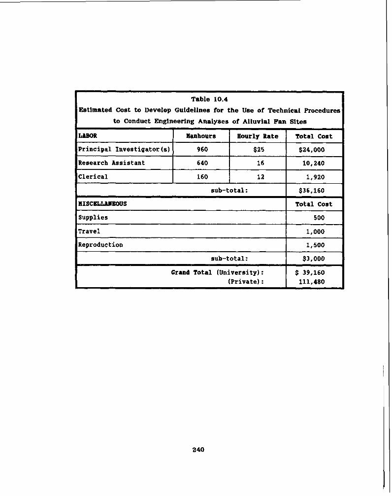
Estimated Cost to Develop Guidelines for the Use of Technical Procedures

Table 10.6
Estimated Cost to Determine Potential for Aqulfer Contamination on
Urbanizing Alluvial Fan Sites
ItlLBOR
Principal Investigator (8)
Research Assistant
Clerical
Manhours
960
640
160
sub-total:
HISCELLAHmuS
Well Testing and Laboratory Analysis
Supplies I
$36,160 I
Total Cost
$10,000
1,000
Hourly Rate
$25
16
12
total Cost
$24,000
10,240
1,920

10.2 Section 404 Recomendatione
Although application of Section 404 of t he Clean Water Act to the desert
washes of Arizona has created a n additional administrative burden (as well a s
occasional cost increases and project delays) on both public and private entit ies,
the existence of Natlonwide Permit No. 26 provides a mechanism t o mlnimlze
th i s burden for most proJects.
Under the present structure of the "404" program. ADOT has established
permitting procedures t h a t function very well. No reasons were found to
recommend changes t o these procedures. However, ADOT voiced frustration over
the inability to easily and conslstently identify the "ordinary high water mark"
t h a t i s used t o establish jurisdictional limits of the program.
The Arizona Floodplain Management Association (AFMA) has also voiced
frustration over the Corps interpretation and application of "404" program criteria
to t he ephemeral washes In Arizona. AFMA has opened formal communications
wlth the Corps t h a t critiques the program on the basis of: 1) to,o broad a
jurisdiction; 2) excessive regulation; 3) increased project costs; 4) project time
delays; and 6 ) inability t o consistently identify the ordinary high water mark.
Sufficient criticisms and "gray areas" exist to justify a re-evaluation of
the program a s i t is applied to the desert environment of the southwestern
United States. Although t h e program is a worthwhile environmental protection
package, its jurisdictional limits should be re-evaluated wlth respect to ephemeral
streams; th i s may include nothing more than a more precise and measurable
definition of the "ordinary high water mark", a s it relates to a desert wash.
I t is recommended t h a t a task force, commission, or similar group be officially
sanctioned by the State of Arizona to initiate formal discussions with the Corps
to investigate ways in which the "404" program could be amended to acknowledge
the unique characteristics of the desert environment. Such a task force should
include representation from state , county, and municipal agencies. Environmental
agencies should also be included in this group.

As stated previously, AFMA has already established dialogue with the Corps, in hopes of achieving revisions to the "404" program. The AFMA membershlp is composed of representatives from nearly all major communltles and countles
within the State. Accordingly, th i s organization is capable of voicing the
concerns of a large cross-sectlon of public agencies within Arlzona and, therefore,
would be a valuable participant in any State sanctioned task force.
Task force dlscusslons should focus on specific problems tha t the various
organizations perceive a s being related to compliance with the program. Efforts
should be made durlng these discussions to establish criteria for a "regional
permit" t ha t would be an acceptable compromise t o all parties. The jurisdictional
limits of this permit should be defined in terms of easily understood and
measurable parameters t h a t can readily be established in the field. These
parameters should reflect the characteristics of the desert fluvial system.
The pursuit of direct, officially sanctioned discussions with the Corps of
Engineers will provide a forum for a frank exchange of Ideas t h a t could be used
to improve compliance with the "404" program in Arizona.

Bibliography
Alvarez, D., Wang, W.C., Dawdy, D.R., Analvsis o f Alluvlal Fan Flooding,
Water Forum 86, ASCE
Anderson-Nlchols & Company, Inc., Fl00d~la in Manaaement Tools For Alluvial Fans, prepared for FEMA, Contract No. EMW-C-0176, 1981. -
Anderson-Nichols & Company, Inc., Flood Control S tudy for Bullhead Ci ty ,
Bivlera Communitles. A r l m , Arizona Department of Water Resources, 1986.
Barnett, D.W., Section 404 of t he Clean Water Act. An Evaluation o f the Issues dt Permf t Pronram Im~lementation i n Western color ad^, 1982
Blissenbach, E., Ceoloav o f AIIuvlal Fans in Semiarid Realons, Bulletin of the Geological Soclety of America, Volume 66, 1964.
Bond, L.A., Handbook for Arizona Comrnunitles on Fl00d~l8in Manaaement and the N8tiontkl Flood Insurance ProBrain, Arizona Department of Water Resources, 1982, revised 1986.
Bull, W.B., D All- - Fan Env- , Progress and Physical Geography, Volume 1, 1977.
Bull, W.B., Relation of T e x t T D+?D-, Journal of Sedimentary Petrology, 32, 1962.
Bull, W.B., Alluvial Fans, Journal of Geological Education, 1968
Bull, W.B., -nv of S e ~ w d w i d F u tn W e s w F r w Count-v. California, USGS Professional Paper 362-E, 1964
Carryer, S.J., A Note on the Formation o f Alluvial Fane, New Zeaiand Journal of Geology and Geophysics, 1965
Carter, R.M., Mass-Emplaced Sand-Ffn~ers a t Mararoa Construction Site, Southern New Zealand, Sedimentology, 22, 1976.

Cella Barr Associates, Tortolita Fan Area Basin Mananement P14Utphase and Phase IA, 1986, revlsed 1987.
Chang, H., p l u v m c s of D e M & -, Journal of Hydraulic Engineering, Nov. 1982, ASCE
Chang, H.R., & & g e n t Studv for Flood Control Plan of Bullhead City. Arizona, prepared for Kaminski-Hubbard Engineering, 1988.
Chawner, W.D., Alluvial Fan F l o ~ w h f Th J934, Geographical Review 26, 1936
Cooke, R.U., Warren, A,, Geomor~holoclv in Deserts, 1973
DMA Consulting Engineers, Alluvial Fan Floodinn Methodolo~v. An Analvsis, 1986.
Denny, C.S., Fans and Pediments, American Journal of Science, Volume 266, 1967.
Denny, C.S., Mluvtal a k a n d N&x&ft?, USGS Professional Paper 466, 1966.
Department of Defense, Corps of Engineers, -Rro~eaulatnrvm -s, 33 CFR, Parts 320 through 330, Federal Register, November 13, 1986
Doehring, D.O., piscrimination of Pediments and Alluvial Fans fiom TODO- gra~hlc Mans, Bulletin of the Geological Society of America, Volume 81, 1970.
Drew, F., A 11 u vial and Lacus trine De~osits and Glacial Records of the V D D ~ ~ Ddus B w , London Quarterly Journal, Geological Society, 29, 1873.
Eckls, R., E e r n C-,
Journal of Geology 36, 1928
Federal Insurance Administration (FIS), Anencv (FEMA). Risk Studies Com~letion and Full P r o m Status, 1984

Federal Emergency Management Agency, A to Flood Insurance Maps. A Guide for Communltv Officials, 1986
Federal Emergency Management Agency, -d I n s ~ c e = a and Related Reauhtlons, 44 CFR, Chapter 1, Subchapter B, October 1, 1986
French, R.H., c n of the Methodolow, University of Nevada Desert Research Institute Publication No. 46040
French, R.H., n, Book published by Elsevier Publishing Company
Gllluly, J., PhysiQgra~hv of the Alo Region. Arizona, Bulletin of the Geological Society of America, Volume 48, 1937.
Glennie, K.W., s, Elsevler, Amsterdam, 1970
Goddard, J.E., a Administratioq, March 1976
Hadley, R.F., Pediments and Pediment-Forminn Processes, Journal of Geo- logical Education 16, 1967
Hooke, R.L., Processes on Arid Renlon Alluvial Fans. Journal of Geology, Vol. 76, 1967
Howells, D.H., m a n Flood M u e m e n t ; Problems and Research Need& Journal of the Water Reeources Planning and Management Division, ASCE, 1977
James, L.D., Pitcher, D.O., Heefner. S., Hall, B.R., Paxman, S.W., Weston, A., pfood Risk Below S t e e ~ M o u n & & ~ g , Water Forum 86, ASCE
James, Larson, Hoggan, & Glover, Flood-ent Needs PecuNar To Arfd, Water Reeources Bulletin, Vol. 16, No.6, Dec, 1980
Kaminski-Hubbard Engineering, Inc., Mohave Countv Alrport/Bmead C f t v pro~osed Flood Control P& Mohave County Flood Control Dietrict, May 1987 & October 1987 (Volume 1.00).

Kumar, S., & u g , & e e r i n n v For Delinea tinn Debris Flow Hazards & Los Anneles County, Water Forum 86, ASCE.
Langbein, W.B. and Schumm, S.A., &&i o f Se- t o Megn Annual Preci~itation, Transactions of the American Geophysical Union,
39, 1968.
Los Angeles District, U.S. Army Corps of Englneers, E n ~ i n e e r i n ~ Standards For Flood Protection Of Sinnle Lot DeveloDments on Alluvial m, prepared for FEMA, (undated).
Lustig, L.K., Com~etence o f Trd~lsDort on Alluvial Fans, USGS Professional Paper 476-C, 1963.
Lustig, L.K., Clastic Sedfmentation i n D e e ~ SDrlnns Valley. Califor&, USGS Professional Paper 362-F, 1966.
Magura & Wood, -rd Identification & Flood~lain M a m e n t pa j411uvlal Fang, Water Resources Bulletin, Vol. 16, No.1, Feb. 1980.
Malone, J., Alluvial Fan Floodinn. Cornouter Promam, Soil Conservation Service, March 197 1.
Melton, M. A ., The Geomor~hic and Paleoclimatlc Si~nif lcance of Alluvial B ~ ? D o s ~ ~ s i n Southern Arizone, Journal of Geology, 73, 1966.
Packard, F.A., H~draulic Geometrv o f a Discontinuous Eohemeral Stream on a Baiada Near Tucson. Arizona, University of Arizona, Ph D. Dissertation 1974.
Plma County Department of Transportation & Flood Control District, ADD^^ & the hJ, 1987.
Price, W.E., Jr., S l m u l a t i o n Fan De~osition by a Random W& Nod& Water Resources Research, Vol. 10, No.2, April 1974.
Rachocki, A., Ailuvial Fans. An Attempt a t an Em~irical A D D ~ o ~ c ~ , a Wiley-Interscience Publication, 198 1.

Ryder, J.M., The Str&kxwhv and M o r ~ h o l o ~ v of Para - Glacial Fans l~ South-Central Brftish Columbia, Canadlan Journal of Earth Science, 8,
1971a.
Ryder, J.M., $ome A s ~ e c t s o f the Mor~hometrv o f Para-Glacial Alluvial Fans fn South-Central Britfsh Columbia, Canadian Journal of Earth Science,
8, 1971b.
Sabol, G.V., Urban Flog Q, Water Forum 81, ASCE.
Schick, A.P., Alluvial Fans and Desert Roads. A Problem in A ~ ~ l l e d Ceomor~ho lo~v , Abhandlungen Akademle der Wissenschaften, Cottingen, Mathematisch, Physikalische Klasse, 111. Folge, Nr. 29, pages 418-425, 1974.
Scott, K.M., USGS Professional Paper, 732-B &?our 1 FU in Tui- A Fanhead Valley in Urban Southern California, 1969.
Sharp, R.P., -, Journal of Geomorphology, Volume 6, 1942.
Simons, Li & Associates,Inc.. State-of-the-Art. Analysis Of Flows On Alluvlal M s . January 1988.
Tator, B.A., Pedfment Characteristics and Termfnology, Association of American Geographer Annals, Part I, Vol. 42, 1962, Part 11, Vol. 43,
1963.
Troeh, F.R., Landfom Eauatlons Fitted To Contour M a ~ s . American Journal of Science, Vol. 263, 1966.
U.S. Army Corps of Engineers, m t o r v P- A ~ ~ l i c a n t m a t i o n -, May 1986.
U.S. Army Corps of Engineers (Omaha District), Of Mudflows Into Flood Studies On Alluvlal Fans, August 1988.
U.S. Army Corps of Englneers (Los Angeles District), Ennineerina Standards
r r ec Fo Flood P ot tion Of Single Lot Deve lo~ments on Alluvial Fans, Draft Report

Water Resources Associates, Inc. & Robert L. Ward, Consulting Engineer, General Drainane Plan for North Scottsdale. Arizona, 1988.
Wasson, R.J., Catchment Processes and the E v ~ L ~ t i o n of Alluvldl FdUrSfLl t he Lower Derwent Valley. Tasmania, Zeitschr. Geomorph. N.F. 21,
1977a.
Wasson. R.J., Last Glacial Alluvial Fan Sedimentation in the Lower Derwent
Valley. Tasinsnls(, Sedimentology. 24. 1977b.
Wyckof f , J . , Rock. Time. and Landforms, Harper & Row, New York, 1966.


![Evaluation ofhydrologic parameters in a semiarid rangeland ... · Evaluation ofhydrologic parameters in a semiarid rangeland using remotely sensed spectral data ... [Rosema, 1990],](https://img.pdfslide.us/doc/110x75/5b365c827f8b9a6b548e6079/evaluation-ofhydrologic-parameters-in-a-semiarid-rangeland-evaluation-ofhydrologic.jpg)