Embed Size (px)
Citation preview
SPP Reliability CoordinatorTLR 5 Analysis Report for the
ICT Reliability Area
MAINTAINED BY SPP Reliability Coordinator
PUBLISHED: 10/11/2010 LATEST REVISION: 10/12/2010
Copyright © 2010 by Southwest Power Pool, Inc. All rights reserved.
Exhibit RCR-4 Docket No. UD-07-03 January 4, 2011
10-011-U APSC 1-2 Add 11 LR14573
APSC FILED 1/5/2011 3:42:44 PM Doc. 284
TLR 5 Analysis Report for the ICT Reliability Area
1
Table of Contents
Table of Contents .................................................................................................................................................. 1�
1. Executive Summary ......................................................................................................................................... 2�
2. TLR 5 Statistics ................................................................................................................................................ 3�
3. TLR 5 Events by Flowgates ............................................................................................................................. 4�
Arkansas ............................................................................................................................................................. 4�1324 - Whitebluff-Sheridan for loss of Mabelvale-Sheridan ........................................................................... 4�1913 - Keo-West Memphis 500 kV for the loss of Independence-Dell 500 kV .............................................. 5�1966 - Sheridan - Mabelvale 500 kv ftlo White Bluff - Keo 500kv .................................................................. 5�14804 - Russellville E-Russellville S 161 kv FTLO ANO - Ft. Smith 500kv ................................................... 6�16556 - Russellville E-Russellville S 161 kv FTLO ANO-Ft.Smith 500kv (MKT COOR) ............................... 7�16288 - Marshall-Botkinburg 161 kv ftlo Dardanelle Dam-Russellville S. 161kv ........................................... 7�16314 - Mabelvale-Bryant 115 KV for the loss of Sheridan - Mabelvale 500KV ............................................ 7�16445 - Wmemphis - BirmingST 500 KV FTLO SanSouci-Shelby 500KV..................................................... 8�16470 - Melbourne-Calico Rock 161 kV ftlo ISES-Dell 500kV ....................................................................... 8�16500 - Sage-Melbourne 161 kV FTLO Independence-Dell 500 kV.............................................................. 9�
Louisiana ........................................................................................................................................................... 10�1347 - Wilbert-Livonia for loss of Webre-Wells ............................................................................................ 10�15867 - Webre-Willow Glen 500 kv ftlo Big Cajun-Fancy 500 kv ................................................................. 10�16132 - Nelson-LakeCharlesBulk1 138 kv for the loss of Nelson-Richard 500kv ........................................ 11�
Louisiana/Texas ................................................................................................................................................ 12�1388 - Mt. Olive - Hartburg for the loss of Webre - Wells............................................................................. 12�16272 - Nelson AT1 500/230 for the loss of Hartburg 500kv - Cypress....................................................... 12�
Mississippi ......................................................................................................................................................... 13�1330 – McAdams 500-230 for loss of McAdams-Lakeover.......................................................................... 13�16373 - McAdams-Pickens 230 kV ftlo McAdams-Lakeover 500kV ............................................................ 13�16487 - McAdams AT1 ftlo Choctaw-West Point 500kV .............................................................................. 14�
4. TLR/LAP Overlap Assessment Process ...................................................................................................... 15�
5. Conclusion ...................................................................................................................................................... 18�
Exhibit RCR-4 Docket No. UD-07-03 January 4, 2011
10-011-U APSC 1-2 Add 11 LR14574
APSC FILED 1/5/2011 3:42:44 PM Doc. 284

TLR 5 Analysis Report for the ICT Reliability Area
2
1. Executive Summary
This report analyzes Transmission Loading Relief (TLR) level 5 events issued by the Southwest Power Pool (SPP) Reliability Coordinator in the Independent Coordinator of Transmission (ICT) reliability area. The analysis used statistical data from January 1, 2010 through September 30, 2010, and is divided into three sections: total number of TLR 5 events, arrangement of TLR 5 events by flowgates, and the overlap of TLR and Local Area Problem (LAP) flowgates.
The TLR 5 events are arranged by the state, in which the flowgate contingent element is located, and include the flowgate name and interchange distribution calculator (IDC) identifier, dates and number of events and TLR level for the flowgate during the reporting period, cause of the TLR 5 event, and a proposed mitigation plan to limit future TLR 5 events on the flowgate. The report also includes a list of each state’s total number of TLR5s and amount of firm curtailment in gigawatt hours.
The overlap of TLR/LAP flowgates is listed, along with an explanation of the transmission congestion management assessment process. This explanation includes the assessment formula for determining the TLR or LAP and an example of the calculation using the formula.
The SPP Reliability Coordinator makes the following recommendations:
� Perform off-peak engineering analysis on all transmission outages. � Schedule transmission upgrades as soon as possible on the flowgates with the greatest
TLR 5 activity. � Provide greater accuracy between the projected generation and the actual generation in
the Available Flowgate Capacity (AFC) model. � The SPP Reliability Coordinator should be given approval rights for generation outages in
the ICT reliability area.
This report acknowledges the following limitations to the analysis performed on the TLR 5 events:
� The research is from the SPP Reliability Coordinator’s perspective and does not include economic considerations.
� It is difficult to project generation dispatch in real-time. � Most of the TLR 5 activity is on the 500 kV transmission grid, which is owned by Entergy
but used by multiple entities.
Exhibit RCR-4 Docket No. UD-07-03 January 4, 2011
10-011-U APSC 1-2 Add 11 LR14575
APSC FILED 1/5/2011 3:42:44 PM Doc. 284

TLR 5 Analysis Report for the ICT Reliability Area
3
2. TLR 5 Statistics
The following chart represents the TLR 5 activity by state and gigawatt hours curtailed.
For the ICT footprint, the 500 kV transmission grid in Arkansas incurred 73% of gigawatt hours curtailed and 60% of TLR 5 events.
State # TLR5's GWHArkansas 44 87.18Louisiana 8 6.92
Louisiana/Texas 9 17.79Mississippi 12 8.20Grand Total 73 120.09
Exhibit RCR-4 Docket No. UD-07-03 January 4, 2011
10-011-U APSC 1-2 Add 11 LR14576
APSC FILED 1/5/2011 3:42:44 PM Doc. 284

TLR 5 Analysis Report for the ICT Reliability Area
4
3. TLR 5 Events by Flowgates
Arkansas
1324 - Whitebluff-Sheridan for loss of Mabelvale-Sheridan
TLR Date Return To Zero Level 4/30/2010 23:15 5/1/2010 13:30 5a 5/15/2010 22:00 5/17/2010 06:40 5b 5/17/2010 23:00 5/18/2010 06:40 5a 5/18/2010 22:00 5/19/2010 05:45 5b 5/19/2010 22:00 5/20/2010 06:30 5a 5/20/2010 21:45 5/21/2010 06:45 5a 5/21/2010 22:20 5/22/2010 10:25 5b
Cause:This is an off-peak issue created because of a north-to-south power transfer during the off-peak hours. Nelson 6 is a coal unit in the south portion of the Entergy system that was not available during this time due to planned maintenance activities.
Mitigation Plan:This issue is addressed in the 2009 ICT Strategic Transmission Expansion Plan (ISTEP). There are two short-term opportunities to limit TLR 5 activity on this flowgate:
� A generation ratio between the north and south generation should be established to limit the north to south power transfer. The appropriate ratio would be determined by engineering analysis and could be established on a daily or seasonal basis.
� The second opportunity for mitigation would be to provide the Reliability Coordinator with approval authority for planned generation outages. Currently, the Reliability Coordinator manages the system without this authority; in many instances, generation maintenance activities create transmission constraints that require the congestion management process to relieve the constraint.
Exhibit RCR-4 Docket No. UD-07-03 January 4, 2011
10-011-U APSC 1-2 Add 11 LR14577
APSC FILED 1/5/2011 3:42:44 PM Doc. 284
TLR 5 Analysis Report for the ICT Reliability Area
5
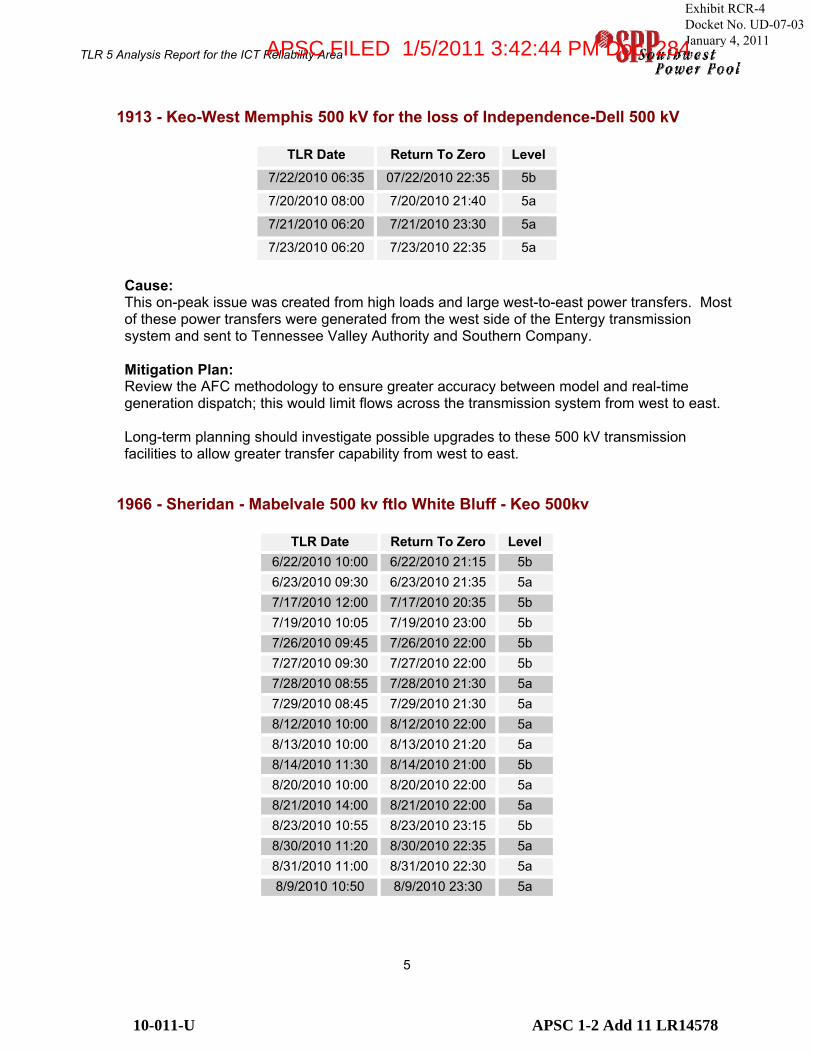
1913 - Keo-West Memphis 500 kV for the loss of Independence-Dell 500 kV
TLR Date Return To Zero Level
7/22/2010 06:35 07/22/2010 22:35 5b
7/20/2010 08:00 7/20/2010 21:40 5a
7/21/2010 06:20 7/21/2010 23:30 5a
7/23/2010 06:20 7/23/2010 22:35 5a
Cause:This on-peak issue was created from high loads and large west-to-east power transfers. Most of these power transfers were generated from the west side of the Entergy transmission system and sent to Tennessee Valley Authority and Southern Company.
Mitigation Plan:Review the AFC methodology to ensure greater accuracy between model and real-time generation dispatch; this would limit flows across the transmission system from west to east.
Long-term planning should investigate possible upgrades to these 500 kV transmission facilities to allow greater transfer capability from west to east.
1966 - Sheridan - Mabelvale 500 kv ftlo White Bluff - Keo 500kv
TLR Date Return To Zero Level 6/22/2010 10:00 6/22/2010 21:15 5b 6/23/2010 09:30 6/23/2010 21:35 5a 7/17/2010 12:00 7/17/2010 20:35 5b 7/19/2010 10:05 7/19/2010 23:00 5b 7/26/2010 09:45 7/26/2010 22:00 5b 7/27/2010 09:30 7/27/2010 22:00 5b 7/28/2010 08:55 7/28/2010 21:30 5a 7/29/2010 08:45 7/29/2010 21:30 5a 8/12/2010 10:00 8/12/2010 22:00 5a 8/13/2010 10:00 8/13/2010 21:20 5a 8/14/2010 11:30 8/14/2010 21:00 5b 8/20/2010 10:00 8/20/2010 22:00 5a 8/21/2010 14:00 8/21/2010 22:00 5a 8/23/2010 10:55 8/23/2010 23:15 5b 8/30/2010 11:20 8/30/2010 22:35 5a 8/31/2010 11:00 8/31/2010 22:30 5a 8/9/2010 10:50 8/9/2010 23:30 5a
Exhibit RCR-4 Docket No. UD-07-03 January 4, 2011
10-011-U APSC 1-2 Add 11 LR14578
APSC FILED 1/5/2011 3:42:44 PM Doc. 284

TLR 5 Analysis Report for the ICT Reliability Area
6
Cause:This is typically an on-peak issue resulting from south-to-north power flow due to off-system sales from an internal generation-only control area. Amite South and Gulf States Utilities (GSU) are dispatched to serve native load during high load periods. Mitigation Plan: Review AFC model to ensure that generation dispatch in the model is comparable to real-time generation dispatch.
Long-term planning should investigate transmission upgrades to provide additional transfer capability to support off-system sales.
The North-to-south generation ratio recommended in the ICT Reliability Improvement Plan would assist in managing this transmission constraint.
14804 - Russellville E-Russellville S 161 kv FTLO ANO - Ft. Smith 500kv
TLR Date Return To Zero Level 8/9/2010 15:30 8/9/2010 18:00 5b
Cause:OG&E de-rated several units when a 345 kV transmission line from Ft. Smith to Muskogee tripped due to grass fire underneath line. Generation at the Muskogee generation plant also tripped for unrelated reasons on August 9, 2010. The combination of these events led to a reverse flow on the Entergy ANO – Ft. Smith 500 kV line, which is the contingent element for this flowgate. The flow on the contingent element created the constraint and required the TLR action.
The market-coordinated flowgate listed below (16556) was created at 18:00 on August 9, 2010 to achieve the required relief from the SPP market that was not available until the original flowgate (14804) was coordinated with the market.
Mitigation Plan: There is no mitigation planned for this event, as it was created by a forced outage on the transmission system.
Exhibit RCR-4 Docket No. UD-07-03 January 4, 2011
10-011-U APSC 1-2 Add 11 LR14579
APSC FILED 1/5/2011 3:42:44 PM Doc. 284
TLR 5 Analysis Report for the ICT Reliability Area
7
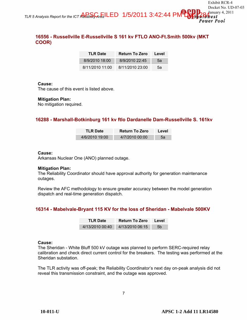
16556 - Russellville E-Russellville S 161 kv FTLO ANO-Ft.Smith 500kv (MKT COOR)
TLR Date Return To Zero Level 8/9/2010 18:00 8/9/2010 22:45 5a
8/11/2010 11:00 8/11/2010 23:00 5a
Cause:The cause of this event is listed above.
Mitigation Plan: No mitigation required.
16288 - Marshall-Botkinburg 161 kv ftlo Dardanelle Dam-Russellville S. 161kv
TLR Date Return To Zero Level 4/6/2010 19:00 4/7/2010 00:00 5a
Cause:Arkansas Nuclear One (ANO) planned outage.
Mitigation Plan: The Reliability Coordinator should have approval authority for generation maintenance outages.
Review the AFC methodology to ensure greater accuracy between the model generation dispatch and real-time generation dispatch.
16314 - Mabelvale-Bryant 115 KV for the loss of Sheridan - Mabelvale 500KV
TLR Date Return To Zero Level 4/13/2010 00:40 4/13/2010 06:15 5b
Cause:The Sheridan - White Bluff 500 kV outage was planned to perform SERC-required relay calibration and check direct current control for the breakers. The testing was performed at the Sheridan substation.
The TLR activity was off-peak; the Reliability Coordinator’s next day on-peak analysis did not reveal this transmission constraint, and the outage was approved.
Exhibit RCR-4 Docket No. UD-07-03 January 4, 2011
10-011-U APSC 1-2 Add 11 LR14580
APSC FILED 1/5/2011 3:42:44 PM Doc. 284

TLR 5 Analysis Report for the ICT Reliability Area
8
Mitigation Plan: The Reliability Coordinator should perform off-peak analysis for all request outages; the off-peak model is being created for this analysis.
16445 - Wmemphis - BirmingST 500 KV FTLO SanSouci-Shelby 500KV
TLR Date Return To Zero Level 7/24/2010 09:55 7/24/2010 22:30 5a 7/30/2010 09:00 7/30/2010 22:00 5a 8/16/2010 8:00 8/16/2010 21:40 5a 8/17/2010 9:00 8/17/2010 21:35 5b 8/18/2010 8:00 8/18/2010 21:40 5a 8/19/2010 9:00 8/19/2010 21:40 5a
Cause:This on-peak issue was created from high loads and large west-to-east power transfers. Most of these transfers were generated from the west side of the Entergy transmission system and sent to Tennessee Valley Authority and Southern Company.
Mitigation Plan: Review the AFC methodology to ensure greater accuracy between model and real-time generation dispatch; this would limit flows across the transmission system from west to east.
Long-term planning should investigate possible upgrades to these 500 kV transmission facilities to allow greater transfer capability from west to east.
16470 - Melbourne-Calico Rock 161 kV ftlo ISES-Dell 500kV
TLR Date Return To Zero Level 7/14/2010 10:20 7/14/2010 22:55 5b 7/15/2010 19:00 7/15/2010 22:00 5a 8/10/2010 20:00 8/10/2010 22:15 5a
8/9/2010 9:00 8/9/2010 23:30 5b
Cause:This issue was caused by south-to-north power transfers due to high loads in the area; additional impact was caused by the lack of Southwestern Power Administration (SPA)hydro generation due to water restrictions placed by the Army Corps of Engineers.
Mitigation Plan: The 161 kV transmission system should be evaluated for transmission upgrade opportunities due to increasing load in the area. No upgrades are planned for this area at this time.
Exhibit RCR-4 Docket No. UD-07-03 January 4, 2011
10-011-U APSC 1-2 Add 11 LR14581
APSC FILED 1/5/2011 3:42:44 PM Doc. 284

TLR 5 Analysis Report for the ICT Reliability Area
9
16500 - Sage-Melbourne 161 kV FTLO Independence-Dell 500 kV
TLR Date Return To Zero Level 7/15/2010 10:30 7/15/2010 19:00 5b
Cause:This event was declared on the incorrect line section; 16470 was the correct flowgate for this transmission constraint. At 19:00 on 7/15/10, the Reliability Coordinator switched the TLR activity to the correct flowgate. There was no adverse impact from this action, as the same relief requirements are in effect for both flowgates.
Mitigation Plan: The mitigation plan for 16470 also applies to this flowgate.
Exhibit RCR-4 Docket No. UD-07-03 January 4, 2011
10-011-U APSC 1-2 Add 11 LR14582
APSC FILED 1/5/2011 3:42:44 PM Doc. 284

TLR 5 Analysis Report for the ICT Reliability Area
10
Louisiana
1347 - Wilbert-Livonia for loss of Webre-Wells
TLR Date Return To Zero Level 4/9/2010 05:00 4/9/2010 22:40 5b
Cause:The Nelson 6 generating unit was in a planned maintenance outage, which reduces generation on the west side of the Entergy system that is available to balance flow across the contingent 500 kV Webre–Wells element.
Mitigation Plan: The Reliability Coordinator should have approval authority for generation maintenance outages.
This was a single occurrence, so no other mitigation action is planned at this time.
15867 - Webre-Willow Glen 500 kv ftlo Big Cajun-Fancy 500 kv
TLR Date Return To Zero Level 7/8/2010 11:00 7/8/2010 21:35 5a 7/31/2010 08:40 7/31/2010 21:00 5a 8/1/2010 09:50 8/1/2010 22:00 5a 8/2/2010 09:00 8/2/2010 20:50 5a 8/3/2010 08:00 8/3/2010 20:40 5a 8/4/2010 08:00 8/4/2010 18:45 5b
Cause:On 7/8/10, the Ninemile 4 generating unit was forced offline due to a tube leak in the boiler.
All other TLR events on this flowgate were due to the Riverbend planned outage to correct an ID fan problem.
Mitigation Plan: No mitigation is planned at this time; the circumstances that created the TLR event were either forced or associated with a Nuclear Regulatory Commission (NRC) directive to make repairs to the nuclear unit. The load was high during this time; typically the units would have been in service.
Exhibit RCR-4 Docket No. UD-07-03 January 4, 2011
10-011-U APSC 1-2 Add 11 LR14583
APSC FILED 1/5/2011 3:42:44 PM Doc. 284

TLR 5 Analysis Report for the ICT Reliability Area
11
16132 - Nelson-LakeCharlesBulk1 138 kv for the loss of Nelson-Richard 500kv
TLR Date Return To Zero Level 7/8/2010 16:00 7/8/2010 21:20 5a
Cause:The Whitebluff #2 generation unit was offline due to a tube leak, and was replaced with generation from the Sabine and Lewis Creek units, which has a negative impact on this flowgate.
Mitigation Plan: This was a one-time occurrence created by a forced outage on a major generating plant that is typically dispatched during high load periods; there is no mitigation plan.
Exhibit RCR-4 Docket No. UD-07-03 January 4, 2011
10-011-U APSC 1-2 Add 11 LR14584
APSC FILED 1/5/2011 3:42:44 PM Doc. 284

TLR 5 Analysis Report for the ICT Reliability Area
12
Louisiana/Texas
1388 - Mt. Olive - Hartburg for the loss of Webre - Wells
TLR Date Return To Zero Level
9/25/2010 2:35 9/27/2010 19:50 5b
Cause:The Nelson 6 generating unit was forced offline due to a tube leak.
Mitigation Plan: The circumstances that led to this TLR event do not require a mitigation plan.
16272 - Nelson AT1 500/230 for the loss of Hartburg 500kv - Cypress
TLR Date Return To Zero Level 3/23/2010 08:00 3/23/2010 16:00 5a 4/30/2010 10:30 5/1/2010 01:40 5a 5/16/2010 08:00 5/16/2010 22:50 5b 5/17/2010 09:55 5/17/2010 22:45 5a 5/19/2010 09:25 5/19/2010 23:20 5b 9/18/2010 10:00 9/18/2010 23:00 5b 9/19/2010 9:45 9/20/2010 0:40 5a 9/25/2010 6:00 9/25/2010 22:40 5a
Cause:The TLR 5 events for March through May were created by the planned maintenance outage of the Nelson 6 generating unit. The TLR 5 events for September were due to a forced outage of Nelson 6.
Mitigation Plan: The Reliability Coordinator should have approval authority for generation maintenance outages.
No other mitigation plan has been created.
Exhibit RCR-4 Docket No. UD-07-03 January 4, 2011
10-011-U APSC 1-2 Add 11 LR14585
APSC FILED 1/5/2011 3:42:44 PM Doc. 284

TLR 5 Analysis Report for the ICT Reliability Area
13
Mississippi
1330 – McAdams 500-230 for loss of McAdams-Lakeover
TLR Date Return To Zero Level 2/12/10 07:00 2/12/10 13:25 5a
4/19/2010 12:55 4/20/2010 00:55 5a 5/11/2010 08:30 5/12/2010 00:40 5b 5/19/2010 20:00 5/20/2010 00:45 5a 5/21/2010 15:00 5/21/2010 18:40 5b 5/23/2010 22:20 5/24/2010 03:40 5b
Cause:2/12/10: The Baxter-Wilson-Ray Braswell EHV switch upgrade was in progress as part of the Ouachita project. Loads were higher than expected, and the combination of negative-impacting Entergy and TVA generation created a post-contingent overload that was controlled with a TLR.
4/19/10: The El Dorado–Sterlington 500 kV element was in a planned outage to perform SERC-required relay calibration and check direct current control for the breakers. This testing was performed at the El Dorado substation.
All other TLR 5 events were due to planned outages of the Grand Gulf nuclear generating facility and the Nelson 6 generating facility.
Mitigation Plan: McAdams substation upgrades are planned for 2011.
The Reliability Coordinator should have approval authority for generation maintenance outages
16373 - McAdams-Pickens 230 kV ftlo McAdams-Lakeover 500kV
TLR Date Return To Zero Level 5/18/2010 12:55 5/18/2010 20:45 5b
Cause:The Grand Gulf nuclear facility was in a planned outage.
Mitigation Plan: There is a proposed 230 kV line upgrade on the McAdams–Pickens 230kV line for 2011. This upgrade is also part of the Generation Interconnection study PID 221.
The Reliability Coordinator should have approval authority for generation maintenance outages.
Exhibit RCR-4 Docket No. UD-07-03 January 4, 2011
10-011-U APSC 1-2 Add 11 LR14586
APSC FILED 1/5/2011 3:42:44 PM Doc. 284

TLR 5 Analysis Report for the ICT Reliability Area
14
16487 - McAdams AT1 ftlo Choctaw-West Point 500kV
TLR Date Return To Zero Level 07/22/2010 15:50 07/22/2010 23:00 5b 7/23/2010 11:00 7/23/2010 22:35 5a 7/25/2010 12:35 7/25/2010 22:25 5b 9/1/2010 16:00 9/2/2010 0:00 5a 9/2/2010 12:00 9/2/2010 21:00 5a
Cause:July 2010: The Gerald Andrus generator was offline in an unplanned outage. September 2010: The Gerald Andrus generator was offline in an unplanned outage.
Mitigation Plan: These TLR events were due to unplanned generation outages; there is no mitigation plan other than the McAdams substation upgrades.
Exhibit RCR-4 Docket No. UD-07-03 January 4, 2011
10-011-U APSC 1-2 Add 11 LR14587
APSC FILED 1/5/2011 3:42:44 PM Doc. 284

TLR 5 Analysis Report for the ICT Reliability Area
15
4. TLR/LAP Overlap Assessment Process
The Reliability Coordinator uses two types of congestion management processes to relieve congestion on the Entergy transmission system: the NERC-defined TLR process that provides relief from schedules and generation, and the Local Area Process used to relieve congestion in areas for which only Entergy dispatch can provide relief.
The Reliability Coordinator is responsible for determining the most effective method to provide relief for a transmission constraint, using the following assessment process:
A. The first part of the assessment process describes an interconnect problem (ICP) and is defined as follows:
If the total Firm and Non-Firm Schedule impact on the constrained element/flowgate is greater than 10% of the Post-Contingent Flow, the problem will be deemed an ICP.
All Schedules with a 5% or greater impact will be subject to curtailment during this procedure. The NERC IDC will be used to determine the impact of the schedules on the constrained element/flowgate, and the most current set of NERC TLR procedures will apply.
Problems typically involve interchange transactions with other Balancing Authorities and transmission service reserved under the Entergy OATT and are “regional” in nature, probably caused due to parallel path flows, loop flows, or OATT service.
The formula that represents an ICP during the assessment process is: Interconnection (NF + F) Impact / PC Flow > 10%
An example of this formula is: NF Schedules equals 40 Firm Schedules equals 60 Post Contingent Flow on the limiting element equals 120 (40 +60) = 100 / 120 = .83 or 83% >10%
This issue would be declared by the Reliability Coordinator to be an ICP and the TLR process would be used.
B. The second method for relieving a transmission constraint is the Local Area Problem or LAP, defined below:
If the total Firm and Non-Firm Schedule impact on the constrained element/flowgate is 10% or less than the Post-Contingent Flow, the problem will be deemed a LAP.
All generators with a 3% or greater impact and that meet the other below requirements will be subject to curtailment during this procedure. The generation shift factors will be used to determine the impact of generators on the constrained element/flowgate.
Problems are inside the Entergy Balancing Area and “local” in nature, probably caused due to import limitations, and/or an imbalance between generation and load. Potential
Exhibit RCR-4 Docket No. UD-07-03 January 4, 2011
10-011-U APSC 1-2 Add 11 LR14588
APSC FILED 1/5/2011 3:42:44 PM Doc. 284

TLR 5 Analysis Report for the ICT Reliability Area
16
examples of this type of problem would be the Amite South Area and the GSU Western Division.
The formula that represents an LAP during the assessment process is: Interconnection (NF + F) Impact / PC Flow <= 10%
An example of this formula is: NF Schedules equals 10 Firm Schedules equals 0 Post Contingent Flow on the limiting element equals 120 (10 +0)= 10 / 120 = .08 or 8% >10%
This issue would be declared by the Reliability Coordinator to be a Local Area Problem (LAP) and the Local Area process would be used.
Exhibit RCR-4 Docket No. UD-07-03 January 4, 2011
10-011-U APSC 1-2 Add 11 LR14589
APSC FILED 1/5/2011 3:42:44 PM Doc. 284

TLR 5 Analysis Report for the ICT Reliability Area
17
The Reliability Coordinator has assessed as an Interconnect Problem and Local Area Problem for the following flowgates during the reporting period. These flowgates are subject to either process, depending on the scheduled flow when it was assessed by the Reliability Coordinator.
FGID Description ICP LAP1309 Terrebonne-Greenwood for loss of Webre-Wells 14 21310 Rilla-Riverton for loss of MtOlive-ElDorado 1 41316 Scott-Semere 138kv FTLO Wells-Pont Des Mouton 230kv 66 41330 McAdams500-230 for loss of McAdams-Lakeover 38 31347 Wilbert-Livonia for loss of Webre-Wells 12 61350 North Crowley-Scott 138kV for loss of Richard-Scott 138kV 11 114764 Morrilton-East Gleason ftlo Pleasant Hills-Mayflower 12 114804 Russellville E-Russellville S 161kv FTLO ANO-Ft.Smith 500kv 3 315008 Nelson XF 500/230 ftlo Cyress-Hartburg 500 kv 7 115447 Ringgold-Sailes 115kv ftlo El Dorado-Longwood 500kv 1 115745 Woodstock-Vulchlor 230kV flo Willow Glen-Waterford 500kV 5 1415909 North Crowley - Scott 138kv ftlo Wells - Pont D Mouton 230kv 25 115912 El Dorado 500/115 XFMR (ftlo) Mcneil 500/115 XFMR 1 41 15913 Newton Bulk - Hollysprings 138 kv (ftlo) Hartburg - Cypress 500 kv 1 27 15942 Smackover-Camden 115KV FTLO McNeil AT1 2 33 16177 Cecela Moril 138kv ftlo Scott-Judice 1 116184 Ringgold-Sales 115kV ftlo Dolet Hills-SW Shreveport 345kV 7 11 16272 Nelson AT1 500/230 (ftlo) Hartburg 500kv - Cypress 42 14 16320 Danville_Ola 115kV FTLO Mabelvale-Sheridan 500kV 1 116373 McAdams-Pickens 230kV ftlo McAdams-Lakeover 500kV 3 116398 Jackson Rankin - Jackson Airport 115kv ftlo Rankin AT1 230/115kv 3 90
16418 Blakely-Mountain Pine South 115kv ftlo Hot Springs South-Carpenter Dam 115kv 1 39
16445 Wmemphis-BirmingST 500KV FTLO SanSouci-Shelby 500KV 52 116470 Melbourne-Calico Rock 161kV ftlo ISES-Dell 500kV 16 25 16487 McAdams AT1 ftlo Choctaw-West Point 500kV 1 36 16500 Sage-Melbourne 161kV FTLO Independence-Dell 500 kV 3 716524 Baxter Wilson-Vicksburg SE 115 ftlo Vicksburg-Vicksburg W 115 1 13 16538 Mountain Pine N-Blakely 115kV ftlo Carpenter-Hot Springs S 115kV 1 27 1901 Hot Springs-Bismark for loss of El Dorado-Longwood 2 17 1903 Cecelia-Moril 138 kV for loss of Flanders-Hopkins 138 kV 49 2
1904 Sterlington-Oak Ridge 115 kV for loss of Perryville-Baxter Wilson 500 kV 1 48
1908 Brookhaven-Mallalieu 115 kV for the loss of Franklin-Bogalusa 500 kV 3 49
1911 Hartburg-Inland Orange 230 kV for the loss of Hartburg-Cypress 500 kV 13 20
1920 Mayflower-Morgan 115 kVfor the loss of Mayflower-Sylvan Hills 115 kV 16 31
1923 St. Gabriel-AAC Corp 230 kV for the loss of Coly-Vignes 230 kV 6 22
1927 St. Gabriel-AAC Corp 230 kV for the loss of Willow Glen-Waterford 500 kV 10 21
1946 Newport-Fisher 161 kV for the loss of Independence-Dell 500 kV 1 34
1967 Arkansas (ANO) - Pleasant Hills 500 kv (ftlo) Arkansas - Mabelvale 500 kv 18 1
Exhibit RCR-4 Docket No. UD-07-03 January 4, 2011
10-011-U APSC 1-2 Add 11 LR14590
APSC FILED 1/5/2011 3:42:44 PM Doc. 284
TLR 5 Analysis Report for the ICT Reliability Area
18
5. Conclusion
This report documents the TLR 5 activity during the reporting period and offers the following recommendations:
� Perform off-peak engineering analysis on all transmission outages. � Schedule transmission upgrades as soon as possible on the flowgates with the greatest
TLR 5 activity. � Provide greater accuracy between the projected generation and the actual generation in
the Available Flowgate Capacity (AFC) model. � The SPP Reliability Coordinator should be given approval rights for generation outages in
the ICT reliability area.
The report offers an explanation of the Reliability Coordinator transmission constraint assessment process, and provides examples of the formula used by the Reliability Coordinator during the assessment process.
The report lists the transmission facilities that have been assessed as an Interconnect Problem and a Local Area Problem during the reporting period.
Exhibit RCR-4 Docket No. UD-07-03 January 4, 2011
10-011-U APSC 1-2 Add 11 LR14591
APSC FILED 1/5/2011 3:42:44 PM Doc. 284