Embed Size (px)
Citation preview

SPP 2017 TPL-001-4 Planning Assessment
Scope
Compliance and Advanced Studies

SPP 2017 TPL-001-4 Planning Assessment Scope 1
Revision History
Date or Version Number
Author Change Description
1.0 SPP Staff TWG Approved with minor edits
1.05 SPP Staff Revised to address planned outages for purposes of IRO-017-1. Approved by TWG at May, 2017 meeting.

SPP 2017 TPL-001-4 Planning Assessment Scope 2
Table of Contents Revision History ...........................................................................................................................................1
1. Overview ...........................................................................................................................................4
2. Data inputs ........................................................................................................................................5
2.1. Modeling data ........................................................................................................................5
2.2. Data required by the PC for Steady State Analysis ...............................................................7
2.2.1. Initial Data Request ............................................................................................................7
2.2.2. Subsequent Data Requests .................................................................................................7
2.3. Data required by the PC for Stability Analysis ......................................................................8
2.3.1. Initial Data Request ............................................................................................................8 Member-Submitted Events ....................................................................................................................... 8 Tier 1 Coordinated Events........................................................................................................................ 9
2.3.2. Subsequent Data Requests .................................................................................................9
2.4. Data required by the PC for Short Circuit Analysis ..............................................................9
2.4.1. Initial Data Request ............................................................................................................9
2.4.2. Subsequent Data Requests ...............................................................................................10
2.5. Assessment Area ..................................................................................................................10
3. Steady State Analysis .......................................................................................................................12
3.1. Software ...............................................................................................................................12
3.2. Software parameters.............................................................................................................12
3.3. Monitored facilities ..............................................................................................................12
3.4. Basecase Analysis ................................................................................................................12
3.5. Basecase Contingency Analysis12 ........................................................................................13 3.5.1. Auto N-1 analysis ..................................................................................................................... 13 3.5.2. Auto N-1-1 analysis .................................................................................................................. 13 3.5.3. Long lead time analysis ............................................................................................................ 14 3.5.4. Cascading analysis .................................................................................................................... 14 3.5.5. Protection System analysis ....................................................................................................... 15
3.6. Sensitivity-case Analysis .....................................................................................................15
3.7. Corrective Action Plan (CAP) .............................................................................................15 3.7.1. Transmission Planner CAP ....................................................................................................... 16 3.7.2. Optimal Mitigation Measures (OPM) CAPs ............................................................................ 16

SPP 2017 TPL-001-4 Planning Assessment Scope 3
3.8. Establishment of System Operating Limits (SOLs) and Interconnection Reliability Operating
Limits (IROLs) ....................................................................................................................................... 17 3.9. Deliverables .........................................................................................................................17
4. Stability Analysis ..............................................................................................................................18
4.1. Software ...............................................................................................................................18
4.2. Performance Requirements ..................................................................................................18
4.3. System Intact Analysis .........................................................................................................19
4.4. Contingency Analysis ..........................................................................................................19
4.5. Monitored Quantities ...........................................................................................................20
4.6. Cascading Analysis ..............................................................................................................20
4.7. Corrective Action Plans .......................................................................................................20 4.8. Establishment of System Operating Limits (SOLs) and Interconnection Reliability Operating
Limits (IROLs) ....................................................................................................................................... 21 4.9. Deliverables .........................................................................................................................21
5. Short Circuit Analysis .....................................................................................................................22
5.1. Software ...............................................................................................................................22
5.2. Analysis................................................................................................................................22
5.3. Software parameters.............................................................................................................22
5.4. Corrective Action Plans .......................................................................................................23
5.5. Deliverables .........................................................................................................................23
6. Draft Assessment ..............................................................................................................................24
7. Assessment Distribution ..................................................................................................................25
8. Proposed Schedule for Steady State Analysis ...............................................................................27
9. Proposed Schedule for Stability Analysis ......................................................................................29
10. Proposed Schedule for Short Circuit Analysis ..............................................................................30
11. Proposed Schedule for Draft Assessment ......................................................................................31
12. Changes in Process and Assumptions ............................................................................................32
Appendix A ...................................................................................................................................................33
Appendix B ...................................................................................................................................................34

SPP 2017 TPL-001-4 Planning Assessment Scope 4
1. Overview
This document presents the scope and schedule of work for the NERC TPL-001-4 (TPL) Planning Assessment. This document will be reviewed by the Transmission Working Group (TWG) and the applicable functional entities as described in NERC TPL-001-4 (Standard), A.4.1. Southwest Power Pool (SPP), as the Planning Coordinator (PC1), will coordinate with the Transmission Planners (TP) to exchange data. The assessment will be completed on an annual basis which will not exceed 15 months from the completion of the previous assessment.
1 In this document, SPP does not represent a TP.

SPP 2017 TPL-001-4 Planning Assessment Scope 5
2. Data inputs
2.1. Modeling data Modeling data required in the TPL steady state study is incorporated through the annual SPP Model Development Working Group (MDWG) model building process. The MDWG model building process is performed in accordance with the applicable NERC Modeling, Data, and Analysis (MOD) Standards. In order to meet the R1 requirements2, the models will represent the following:
• Existing Facilities • Known outage(s) of generation or Transmission Facility (ies) with a duration of at least six
months. • New planned Facilities and changes to existing Facilities • Real and reactive Load forecasts • Known commitments for Firm Transmission Service and Interchange • Resources (supply or demand side) required for Load
The model sets in Table 1, Table 2, and Table 3 below establish category P0 as the normal System condition in TPL-001-4 Table 1 and defines the models that will be used for the 2017 TPL analyses.
2.1.1. Steady State Models The models in Table 1 were chosen to comply with requirement R2.1.1, R2.1.2, R2.2.1 (Base case) and R2.1.4 (Sensitivity case). The PC interprets Year one as the current year of the study plus one year. The generation dispatch in the base case models is derived from a member-submitted merit order block dispatch. The sensitivity models will have an alternate dispatch scenario that takes into account wind resources that have firm service. In the sensitivity models, all wind resources that have firm service will be dispatched to represent all firm service sold out of those machines. The dispatch scenario will be equivalent to the dispatch of the ITPNT Scenario 5 models. Requirement Description Base case Sensitivity case R2.1.1 Year 1 peak MDWG 2018S MDWG 2018S (high wind dispatch) R2.1.1 Year 5 peak MDWG 2022S MDWG 2022S (high wind dispatch) R2.1.2 Year 1 off-peak MDWG 2018L MDWG 2018L (high wind dispatch) R2.2.1 Year 10 peak MDWG 2027S N/A
Table 1. Steady State Analysis Study Models
2.1.2. Stability Models The models in Table 2 were chosen to comply with requirement R2.4.1, R2.4.2, R2.4.1 (Base case), R2.4.1 (Sensitivity case), and R2.5. The PC interprets Year one as the current year of the study plus one year. The generation dispatch in the base case models is derived from a member-submitted merit order block dispatch. The sensitivity models will have an alternate dispatch scenario that takes into account wind resources that have firm service. In the sensitivity models, all wind resources that have firm service will be dispatched to represent
2 TPL-001-4 Requirements R1-R1.1.6

SPP 2017 TPL-001-4 Planning Assessment Scope 6
all firm service sold out of those machines. The dispatch scenario will be equivalent to the dispatch of the ITPNT Scenario 5 models. Requirement Description Base case Sensitivity case R2.4.1 Year 1 peak MDWG 2018S MDWG 2018S (high wind dispatch) R2.4.2 Year 1 off-peak MDWG 2018L MDWG 2018L (high wind dispatch) R2.2.5 Year 10 peak MDWG 2027S N/A
Table 2. Stability Analysis Study Models TPL-001-4, Requirement 2.4.1, states that dynamic cases take into account the behavior of induction motors. SPP and their Member companies performed a sensitivity analysis using a generic PSSE load model in a summer peak case in late 2015. The results from this sensitivity analysis indicated the need for additional research regarding the use of a dynamic load models, load specific inputs, and the effects of the dynamic load models on the bulk electric system. The research has included partnering with Electric Power Research Institute (EPRI), leveraging their research on the subject matter, active participation in the NERC LMTF, and the formation of an SPP Dynamic Load Task Force (DLTF) in late 2015. The SPP DLTF has developed a set of industrial and agricultural composite load models and performed benchmark testing in PSSE version 32.2. Based on work performed by the DLTF and the LMTF, there were concerns about the performance of the first generation of the composite load model in PSSE version 32. SPP completed the build of its first cases in PSSE version 33.7 and has obtained a beta version of a second generation composite load model from Siemens-PTI to use in PSSE version 33.7. The benchmarking of this second generation composite load model and development of residential and commercial composite load models is an ongoing task for the DLTF. Once these items have been thoroughly vetted, SPP and it Members will have a composite model representation taking into account residential, commercial, agricultural, and industrial.
2.1.3. Short Circuit Model The model in Table 3 was chosen to comply with requirements of R2.3. The PC interprets Year one as the current year of the study plus one year. The short circuit study model is modified from the models in Table 1 and Table 2 to accommodate the maximum available fault current that interrupting devices will be expected to interrupt with the following modifications:
• Place all available facilities in-service: o Generation o Transmission lines (Out for maintenance) o Transformers o Buses
Requirement Description Base case Sensitivity case
R2.3 Year 1 peak MDWG 2018S Maximum Fault Short Circuit
N/A
Table 3. Short Circuit Analysis Study Model

SPP 2017 TPL-001-4 Planning Assessment Scope 7
2.2. Data required by the PC for Steady State Analysis
2.2.1. Initial Data Request The initial data request focuses on collecting contingencies that will be used during the steady state analysis performed by the PC. During the annual MDWG model build process, a data request will be sent to each applicable stakeholder requesting the TP supply contingency definitions for each planning event as defined in Table 1 of the Standard. The PC requires the TPs follow the SPP contingency naming convention3 when deriving names for each contingency definition. The SPP contingency naming convention will be embedded in the annual data request. The list below summarizes the type of contingency data the PC expects to receive during the annual contingency request.
1. A list of NERC TPL-001-4, Table 1 contingencies that are expected to produce more severe System impacts.
a. Planning events (P1, P2, P4, P5, and P7)4 b. Extreme events (EE.SS.1 – EE.SS.3b)5
2. A list of contingencies on systems adjacent to the TP and PCs Systems which may impact their Systems.6
The TPs and PC will coordinate with adjacent PCs and TPs to ensure Contingencies on adjacent Systems which may impact their Systems are included in the Contingency list. This is an addition to the TP submitted contingencies list.
2.2.2. Subsequent Data Requests The subsequent data requests will focus on collecting the applicable monitored elements, spare equipment facilities, Protection System contingencies, and the Corrective Action Plans (CAPs) for the potential TPL-001-4, R5 voltage and SPP Criteria thermal violations (violations) found during the steady state study performed by the PC. The PC may request additional data to support the study and assessment as needed. The list below summarizes the type of data that will be collected during scheduled Subsequent Data requests.
1. A Bulk Electric System (BES) inclusion list to be monitored in addition to 100 kV and above facilities in the PC footprint.
2. A Spare Equipment strategy facility list.7 o A list of equipment that if lost would result in a year or longer to replace.
3. CAPs to address potential violations found while analyzing the contingency lists studied by the PC.8 3 Appendix B 4 R3.4, The PC will use combinations of P1 events to create P3 and P6 events 5 R3.5 6 R3.4.1 7 R2.1.5 9 R3.3.1

SPP 2017 TPL-001-4 Planning Assessment Scope 8
o A CAP can include but is not limited to model corrections, system adjustments or transmission projects.
o An idev or Python file will be required to represent the changes/adjustments made to the powerflow in order for the PC to verify the effectiveness of the CAP.
4. A list of Protection System contingencies9.
2.3. Data required by the PC for Stability Analysis
2.3.1. Initial Data Request The initial data request focuses on collecting contingencies that will be used during the stability analysis performed by the PC.
Member-Submitted Events The PC will request contingencies from the TPs for analysis. The TP will provide the PC with contingencies as per the PC’s requested Member-Submitted Contingency Spreadsheet format. The PC will generate and validate the submitted contingencies and resolve any discrepancies with the submitting TP. The list below summarizes the type of contingency data the PC expects to receive during the annual contingency request for Planning Events P1-P7 and Extreme Events as defined in Table 1 of the Standard.
1. A list of NERC TPL-001-4, Table 1 contingencies that are expected to produce more severe System impacts.
a. Planning events (P1-P7) and Extreme events b. A maximum of 200 member-submitted events per TP per model. c. Rationale for Event Selection
2. Relay models a. PSS/E Dynamic Relay Models for DYRE file, and/or b. Description of time domain relay actions that replicate the expected removal of elements
3. Description of successful and unsuccessful high speed (less than one (1) second) reclosing into a Fault where high speed reclosing is utilized.
4. Tripping of generators where simulations show generator bus voltages or high side of the GSU voltages are less than known or assumed generator low voltage ride through capability. Include in the assessment any assumptions made or a description of generator low voltage ride through characteristics if not already contained in DYRE file. a. If the TP does not provide generator low voltage ride through characteristics, the PC will
assume low voltage ride through characteristics adhere to PRC-024-2 requirements. Those requirements are given in the Stability Analysis section.
5. Remedial Action Schemes 6. Generic or actual relay models for tripping of transmission lines and transformers where transient
swings cause protection system operations.
9 R3.3.1

SPP 2017 TPL-001-4 Planning Assessment Scope 9
a. If the TP does not provide relay models, PSS/E function “RELSCN” will be used to represent transmission line relays.
7. Specific generator scaling that will be required to balance generation/load when generation is removed as a “prior outage” for a contingency.
Tier 1 Coordinated Events The TPs and PC will coordinate with adjacent PCs and TPs to ensure Contingencies on adjacent Systems which may impact their Systems are included in the Contingency list The PC will communicate with the adjacent PCs to resolve any contingency issues.
2.3.2. Subsequent Data Requests The subsequent data requests will focus on collecting the appropriate system adjustments or Corrective Action Plans (CAPs) for system events exhibiting transient (rotor angle) instability, transient voltage response violations, machine damping violations, voltage stability violations, or potential Cascading. The PC may request additional data to support the assessment, as needed. A CAP is a list of actions and an associated timetable for implementation to remedy a specific problem.
2.4. Data required by the PC for Short Circuit Analysis
2.4.1. Initial Data Request The initial data request only applies to TPs that require ANSI Fault Current calculation. Each TP who requires ANSI calculations will provide to the PC the following ANSI Fault Current Calculation parameters to be used for each bus within the TP area:
• Divisors o For branches in positive sequence o For machines in positive sequence o For branches in zero sequence o For machines in zero sequence
• Fault multiplying factors o DC decrement only or AC and DC decrement
• Max operating voltage, in PU • Contact parting times, in seconds
The TP will provide a listing of each bus number for which a line-out analysis is required for Activity ANSI to be performed by the PC. There is not an initial data request for ASCC results. The PC will run a short circuit analysis on all buses in the short circuit model within the PC footprint.

SPP 2017 TPL-001-4 Planning Assessment Scope 10
2.4.2. Subsequent Data Requests The PC will require Corrective Action Plans for instances where the short circuit current interrupting duty exceeds the equipment rating.10
2.5. Assessment Area At a minimum the PC will monitor the below facilities for the assessment: All BES facilities provided by the TP for TPL compliance Any non-BES facilities provided by the TP for informational purposes All Tie-lines between SPP TPs and in Tier 1 areas
The PC will also monitor all 100 kV and above facilities in the PC footprint. The PC footprint includes the areas listed in the table below.
Area Number Entity Name 520 American Electric Power (AEPW) 542 Board of Public Utilities (BPU) 546 City Utilities of Springfield, MO (SPRM) 523 Grand River Dam Authority (GRDA) 545 Independence Power & Light (INDN) N/A ITC Great Plains, LLC (ITCGP) 541 Kansas City Power & Light Company (KCPL)
54011 KCPL - Greater Missouri Operations (KCPL-GMO) 650 Lincoln Electric System (LES) 531 Midwest Energy, Inc. (MIDW) 640 Nebraska Public Power District (NPPD) 524 Oklahoma Gas & Electric Company (OKGE) 527 Oklahoma Municipal Power Authority (OMPA) 645 Omaha Public Power District (OPPD) 515 Southwestern Power Administration (SWPA) 526 Southwestern Public Service Company (SPS) 534 Sunflower Electric Power Corporation (SECI) 544 The Empire District Electric Company (EDE) 652 Western Area Power Administration (WAPA) 640 Western Area Power Administration (WAPA-RMR)
641 City of Hastings, Nebraska (HAST) 642 City of Grand Island, Nebraska (GRIS)
10 R2.8 11 MDWG Cases Only

SPP 2017 TPL-001-4 Planning Assessment Scope 11
Area Number Entity Name 659 Basin Electric Power Cooperative (BEPC) 536 Westar Energy, Inc. (WR) 525 Western Farmers Electric Cooperative (WFEC)
Table 4. Assessment Area

SPP 2017 TPL-001-4 Planning Assessment Scope 12
3. Steady State Analysis
3.1. Software The software that will be used for the steady state analysis is V&R Energy’s Physical and Operational Margins (POM) suite and PTI’s PSS/E power flow software.
3.2. Software parameters12 POM powerflow solution settings: Full Newton Power Flow Solution Area Interchange Disabled Phase Shift Adjustment Enabled Transformer Tap Stepping Enabled DC Tap Adjustment Enabled Switched Shunt Adjustment Enabled
PSS/E powerflow solution settings: Fixed Slope Decoupled Newton-Raphson Power Flow Solution (FDNS) Area Interchange Disabled Phase Shift Adjustment Enabled Transformer Tap Stepping Enabled DC Tap Adjustment Enabled Switched Shunt Adjustment Enabled Non-Divergent Solution Flag Disabled
3.3. Monitored facilities At a minimum the PC will monitor the below facilities during the contingency analysis: All BES facilities provided by the TP for TPL compliance Any non-BES facilities provided by the TP for informational purposes All Tie-lines between SPP TPs and in Tier 1 areas
The PC will also monitor all 100 kV and above facilities in the PC footprint.
3.4. Basecase Analysis13 After the model building process is complete and approved by the MDWG, the study models will be evaluated for TPL Table 1 planning event P0, system intact, violations. A P0, TPL requirement R5 voltage violation in the steady state occurs when the per unit (pu) voltage of any bus is outside the range of 0.95 pu to 1.05 pu or if a TP has a more or less14 stringent local criteria. A P0 thermal violation occurs when a branch or transformer exceeds 100% of rate A.
12 R3.3.2 13 R3.1 14 With criteria waiver

SPP 2017 TPL-001-4 Planning Assessment Scope 13
Any violation found during the basecase analysis must have a Corrective Action Plan (CAP) submitted to the PC by the TP as scheduled. The PC will apply these CAPs to the applicable base cases before progressing to the contingency analysis.
3.5. Basecase Contingency Analysis13 The PC will gather contingencies from the TPs and other PCs per the Initial Data request. In addition to the TP submitted contingencies, the POM software auto-contingency feature will be utilized to analyze all single (N-1) and combinations of single contingencies (N-1-1). After all contingencies are collected per the schedule, the PC will use the POM software to analyze all the contingencies to determine whether the BES meets the performance requirements through an ACCC analysis. Non-converged contingencies will be further analyzed and potential violations will require the TP to submit a CAP to the PC. A steady state TPL requirement R5 voltage limit violation occurs when after a contingency, the pu voltage of any load serving bus is outside the range of 0.90 pu to 1.05 pu or a more or less15 stringent local criteria. A steady state TPL requirement R5 post-Contingency voltage deviation greater than 0.10 pu on any BES facility shall be flagged and serve as informational purpose only. In cases where the R5 voltage limit violation also exceeds the 0.10 pu voltage deviation, the limit violation will be reported for information only. After a contingency, a thermal violation occurs when a branch or transformer exceeds 100% of rate B.16 The violations derived from the POM software will be verified through PSS/E® to validate the POM results. If a discrepancy is found between the two solutions engines, the results from PSS/E will be used in the violations workbook.
3.5.1. Auto N-1 analysis13 The N-1 analysis will be performed in the power flow software by taking a contingent element out of service, solving the power flow using a Full Newton Power Flow Solution, and scanning the monitored elements for potential violations. Any potential violations found will be reported in spreadsheet format. The auto N-1 contingencies that will be evaluated by the software include:
1. Generator 2. Shunt device 3. Single Pole of a DC line 4. Transmission branch17
3.5.2. Auto N-1-1 analysis13 The N-1-1 analysis will be performed in the power flow software by taking a contingent element out of service, solving the power flow using a Full Newton power flow solution, and scanning the monitored elements for potential violations. If no potential violation occurs, a second contingent element will be taken out of service, the power flow will be solved using a Full Newton power flow solution, and the monitored elements will be scanned for potential violations. Any potential violations found will be reported in 15 With criteria waiver 16 R5 17 Transmission branch = Transformer or Transmission line segment.

SPP 2017 TPL-001-4 Planning Assessment Scope 14
spreadsheet format. The N-1-1 contingencies will be generated in the POM software using the following conditions:
1. All Generators – All Generators >=5% on same facilities 2. All Generators – Transmission branch15 with >=5% GSF 3. All Generators – Shunt device within 10 buses 4. Transmission branch175 – Transmission branch175 in same Zone 5. Transmission branch175 – Shunt device in same Zone 6. Shunt device – Shunt device in same Zone
3.5.3. Long lead time analysis An additional study must be performed when an entity’s spare equipment strategy could result in the unavailability of long lead time equipment.18 If the first element of a P6 event has a long lead time and is not covered in its spare equipment strategy, it will be categorized as being studied for R2.1.5 and will not be studied as a P6 event. A P6 event categorized as R2.1.5 will be studied in accordance with the following steps:
1. Perform a basecase analysis treating each element classified as having long lead time as outaged 2. Check for system intact violations; if any exist report and request CAPs to mitigate 3. With the long lead time element out of service, take additional P1 and P2 elements out of service 4. Check for violations; if any exist report and request CAPs to mitigate 5. Repeat steps 1 through 4 for every R2.1.5 long lead time equipment
If a violation occurs in step 2 or 4, the Corrective Action Plan (CAP) must abide with P0, P1, or P2 as applicable.
3.5.4. Impact Analysis of Planned Outages To comply with new standard IRO-017-1, an evaluation of whether planned outages are the sole cause of, or whether they contribute to the impact of identified issues. The list of identified issues is compared with planned outages. If necessary, additional steady state assessment simulations will be performed with the planned outaged facilities in service to determine if the issues are caused by the planned outage.
3.5.5. Cascading analysis For TPL-001-4 Table 1 P events, if the CAP is able to mitigate the violation the POM-PCM (Potential Cascading Modes) module will not be used since cascading will be prevented by the CAP. The POM-PCM module will be used to detect cascading in the steady state. Contingencies identified during the Table 1 event analysis that yielded monitored elements with thermal loadings over 120% of Rate B and/or pu voltages below 0.90 pu at three (3) or more buses (tripping threshold), are documented and analyzed with POM-PCM. The POM-PCM module will simulate the initial contingency and then take any monitored element out of service if the tripping threshold is exceeded. The powerflow is solved and the system is scanned for elements meeting the tripping threshold again. This tripping, solving, and documenting pattern (tier) is continued until the system becomes stable or cascading occurs.
18 R2.1.5

SPP 2017 TPL-001-4 Planning Assessment Scope 15
In order to reduce the likelihood of cascading, the OPM module will be used to generate a CAP after each violation is discovered but before the elements are tripped offline. The PC will identify potential instances of cascading and send to the TP for verification. If the TP confirms the potential cascading event and the TP provides a CAP to mitigate any of the tripping threshold events, cascading will not occur. If the potential instance of cascading is determined invalid by the TP, the TP will provide justification stating the reason for invalidation. The PC will report on cascading when the simulation results in 3 or more tiers of cascading.19 If the analysis above concludes there is Cascading, and the Cascading is initiated by the occurrence of an extreme event, then an evaluation of possible actions designed to reduce the likelihood or mitigate the consequences and adverse impacts of the event(s) will be conducted.20 The PC will require the possible actions designed to reduce the likelihood or mitigate the consequences and adverse impacts of the event(s).
3.5.6. Protection System analysis Once the potential violation results are provided to the TPs due to the auto N-1, auto N-1-1, and TP submitted contingencies, the TPs will review the results for instances where generators would be tripped by a protection system with automatic controls for bus voltages or high side generation step up (GSU) voltages lower than 0.85 pu.21 The TP will also review the results for instances where Transmission elements would be tripped by a protection system with automatic controls due to relay loadability limits being exceeded.22 After reviewing the results for the above mentioned conditions, the TP will submit to the PC a set of contingencies which include elements that the Protection System will trip offline along with any assumptions made. The PC will analyze the contingencies and report back to the TP any violations found. A CAP will be submitted by the TP to the PC for validation.
3.6. Sensitivity-case Analysis In order to demonstrate a measurable change in System response between the basecase models and the sensitivity models23, a Near-Term Planning Horizon study identical to the analysis described in the Basecase Analysis and Basecase Contingency Analysis sections above shall be performed on the sensitivity models listed in Table 1. It is important to note that Corrective Action Plan(s) do not need to be developed solely to meet the performance requirements for a single sensitivity case analyzed in accordance with Requirement R2, Part 2.1.4. Therefore, the PC will only evaluate contingencies in the sensitivity cases that also caused issues in the non-sensitivity cases. The potential violations found during the sensitivity contingency analysis will require a CAP to be submitted to the PC from the TP.
3.7. Corrective Action Plan (CAP) A Corrective Action Plan is a list of actions and an associated timetable for implementation to remedy a specific problem24. For planning events shown in NERC TPL-001-4 Table 1, when the analysis indicates an inability of the System to meet the performance requirements in NERC TPL-001-4 Table 1, the Planning
19 R6 20 R3.5 21 R3.3.1.1 22 R3.3.1.2 23 R2.1.4 24 http://www.nerc.com/files/glossary_of_terms.pdf

SPP 2017 TPL-001-4 Planning Assessment Scope 16
Assessment shall include system adjustments, model corrections, or CAPs addressing how the performance requirements will be met. The PC will provide the TPs with a workbook (Potential Violation workbook) containing the potential violations for the monitored facilities listed in the Monitored facilities section above. The workbook will contain the model year, season, monitored element, contingent element(s), loading/pu voltage, OPM mitigation if available, and a column for the TP to provide system adjustments, model corrections, or a CAP. If an op-guide is used as a mitigation, the TP will provide the op-guide to the PC for review. Corrective Action Plan(s) do not need to be developed solely to meet the performance requirements for a single sensitivity case analyzed in accordance with Requirements R2, Parts 2.1.4 and 2.4.3.
3.7.1. Transmission Planner CAP A CAP can be many actions over varying timeframes. Some example include: line switching, capacitor adjustments, transformer tap adjustments, generation re-dispatch, etc. A CAP can also be a transmission upgrade as long as the earliest in-service date of the project is prior to the need date of the violation. At a minimum, the project plan should include: project description, schedule of implementation, in-service dates, and lead times. An example of a project plan:
Project: Rebuild and re-conductor x.x miles of abc-def 138 kV line Reason(s): Overloads the 101 MVA RATE B for loss of ghi-jkl 138 kV and several other contingencies in 2024 summer. In-Service Date: 6/1/2024 Lead Time: 24 months Line Rating: 225/315 MVA Other information: This is other pertinent information about the project.
Along with a description of system adjustments or project plans for transmission upgrades, an .idev must be submitted to the PC for use in the verification process when applicable.
3.7.2. Optimal Mitigation Measures (OPM) CAPs The POM software suite Optimal Mitigation Measures (OPM) module will be utilized to aid in generating CAPs. OPM is a tool used to automatically apply mitigation procedures based on operating measures, system adjustments, used by SPP Operations in real-time. CAPs produced by OPM will be presented to the TPs for their review in the violation workbook. In the case when OPM is not able to generate a CAP, TPs will be required to provide a CAP. TPs will also be able to provide an alternate CAP to the OPM CAP if desired. OPM will not be used during N-1 conditions. OPM applies a minimum number of remedial actions based on a priority schedule. The PC will use the following measures when generating OPM CAPs:
• MW Dispatch • MVAR Dispatch • Capacitor and Reactor Switching • ULTC Transformer Tap Change • PAR Transformer Phase Angle Change
Line Switching (In and Out)
SPP 2017 TPL-001-4 Planning Assessment Scope 17
3.7.3. Joint Solution Development with Reliability Coordinator As required by IRO-017-1 R4, analysis of issues caused by planned outages will be identified. The PC will coordinate with the impacted TPs and the RC to develop joint solutions for these identified issues.
3.8. Establishment of System Operating Limits (SOLs) and Interconnection Reliability Operating Limits (IROLs)
Any potential voltage instability conditions that cannot be adequately mitigated with a Corrective Action Plan will be considered to be candidates for potential System Operating Limits (SOLs) that may have a lower rating than the Facility Rating as provided in the study models. For purposes of steady state analysis, contingencies that do not converge will be considered to be potentially unstable25. CAPs can be applied to mitigate potential IROLs. If the TPL-001-4 Steady State results identifies a potential IROL through application of SPP Planning Criteria 7.3.2, then the CAP, in the form of a system adjustment used to mitigate the potential IROL, must be performed within SPP’s IROL Tv . SPP Planning Criteria states that the Planning Horizon IROL Tv is 30 minutes.
3.9. Deliverables After a contingency analysis is complete, the potential violation workbook will be provided to the TPs for their review of the violations, OPM CAPs, and documenting any Transmission Planner CAPs.
25 TPL-001-4 R6

SPP 2017 TPL-001-4 Planning Assessment Scope 18
4. Stability Analysis
4.1. Software The software used for the stability analysis PTI’s PSS/E Powerflow and Dynamics modules, PLI’s DSA Tools TSAT module, V&R Energy’s Fast Fault Screening module of POM.
4.2. Performance Requirements A twenty (20) second time domain simulations will be performed for all events using Siemens’ PTI’s PSS/E Rev 33.7 and the PSSPLT plotting package and PowerTech Labs’ DSATools TSAT (breaker-to-breaker events). As the simulations occur, the following are monitored and recorded to determine stability: Rotor angle stability was monitored for all generators in the SPP PC footprint. Those units that exhibit signs of instability will be marked for further analysis, and should system adjustments or CAPS be necessary, the applicable TP will be coordinated with to determine the necessary system adjustments or CAP. Machines with rotor angle deviations greater than or equal to 16 degrees (measured as absolute maximum peak to absolute minimum peak) shall be evaluated against SPPR1 or SPPR5 requirements below. Machines with rotor angle deviations less than 16 degrees which do not exhibit convergence shall be evaluated on an individual basis. Rotor angle deviations will be calculated relative to the system swing machine. The damping curves will be judged against the SPPR1 and SPPR5 criteria as described in the SPP Disturbance Performance Requirements. Those units that violate the criteria will be identified for further analysis and, should CAPs be necessary, the TP will be engaged to determine the necessary CAP. Transient voltage stability will be monitored for BES buses up to ten (10) buses away from the disturbance (fault) location. The voltage responses shall recover above 0.70 per unit, 2.5 seconds after the fault is cleared. Bus voltages shall not swing above 1.20 per unit after the fault is cleared, unless affected transmission system elements are designed to handle the rise above 1.2 per unit. Those units that violate the transient voltage criteria will be marked for further analysis and should CAPS be necessary, the TP will be engaged to determine the necessary CAP. Generator Voltage Ride-Through Capability26 will be monitored for BES buses up to ten (10) buses away from the disturbance (fault) location. If low voltage ride through capability is not provided by the TP, the PC will assume low voltage ride through capability for all generators to comply with Attachment 2 of PRC-024-2. For generator points of interconnection that do not meet PRC-024-2 requirements, these generators are assumed to trip on low voltage. PRC-024-2 requirements are listed in Table 5.
26 R4.3.1.2

SPP 2017 TPL-001-4 Planning Assessment Scope 19
PRC-024-2 Generator Voltage Ride Through Duration
Voltage (pu) Time (S) <0.45 pu 0.15 <0.65 pu 0.3 <0.75 pu 2.00 <0.90 pu 3.00 ≥1.2 pu Instantaneous trip ≥1.175 pu 0.20 ≥1.15 pu 0.50 ≥1.10 pu 1.00
Table 5. PRC-024-2 Requirements
Tripping of Transmission lines27 – Scanning for potential tripping of transmission lines not cleared by the fault clearing action will be accomplished by use of PSS/E command, “RELSCN”. Cascading - Potential cascading due to a fault event and subsequent rotor angle instability will be determined for NERC category P1-P7 and Extreme events. The criteria for an event resulting in potential cascading is the loss of more than 3000 MW of generation based on SPP’s largest plant output plus 50 percent of the largest unit . Those events violating these criteria were identified as a possible cascading event for further analysis and, should CAPs be necessary, the member entity will be engaged to determine the necessary CAP.
4.3. System Intact Analysis Category ‘P0’ is considered system intact for the base and the sensitivity cases. The ‘P0’ analysis will consist of a 20-second no-fault and a 60-second ring-down simulation to test the integrity of the base and the sensitivity cases.
4.4. Contingency Analysis Stability analysis for disturbance events will be completed using Siemens PTI’s PSS/E and PLI’s DSATools TSAT. Stability performance will be determined for four (4) groups of events:
1. Dynamic Assessment of Member Specified Events: TPs will be requested to provide the PC with reliability contingencies for transient stability analysis. A transient stability analysis will be performed for all member submitted events utilizing PSS/E. 2. Dynamic Assessment of Breaker-to-breaker Contingencies: The PC will gather system breaker-to-breaker data to formulate contingencies that emulate actual field responses to faults. Since faults on line segments between breakers normally cause the line-end terminal breakers to open all line sections, end-to-end de-energization is required during the simulation. The member submitted steady state P1.2 contingencies are representative of line section de-energization. A transient stability analysis will be performed for the formulated breaker-to-breaker contingencies. Powertech Labs, Inc.’s DSATools TSAT will be used for the analysis. The PC will then verify in PSS/E time domain simulation for any events that do not meet the “SPP Transient Stability Requirements”. The TP will be contacted to verify the exact event definition, including fault clearing times to determine if a potential violation exists.
27 R4.3.1.3

SPP 2017 TPL-001-4 Planning Assessment Scope 20
3. Fast Fault Screening Events - V&R Energy’s Fast Fault Scan (FFS) tool will be used to screen for potential category P1 and P6 events at each bus greater than 100kV to determine the more severe fault locations (buses) in the SPP region for each case. These locations will be ranked according to Critical Clearing Times (CCTs). The PC will then verify in PSS/E time domain simulation that critical clearing times are less than 9 cycles. The TP will be contacted to verify the exact event definition, including fault clearing times to determine if a potential violation exists. 4. Dynamic Assessment of Coordinated Events with Tier 1 Entities: Coordination with adjacent PCs will be accomplished. A transient stability analysis will be performed using PLI TSAT for all received events. The PC will then verify in PSS/E time domain simulation for any events that do not meet the “SPP Transient Stability Requirements”. The TP will be contacted to verify the exact event definition, including fault clearing times to determine if a potential violation exists.
4.4.1. Impact Analysis of Planned Outages To comply with new standard IRO-017-1, an evaluation of whether planned outages are the sole cause of, or whether they contribute to the impact of identified issues. The list of identified issues is compared with planned outages. If necessary, additional stability assessment simulations will be performed with the planned outaged facilities in service to determine if the issues are caused by the planned outage.
4.5. Monitored Quantities During the stability simulations, monitored parameters in the assessment area will include
1. Rotor Angle and Speed (The system swing machine at Brown’s Ferry, TVA, will be used as the reference for rotor angle)
2. Real and Reactive Power 3. Bus voltages greater than 100kV in the disturbance Area(s). More than one (1) area may be monitored
depending on proximity to the disturbance. 4. Transient voltage response and machine rotor angle damping will be monitored and compared with the
latest version of the SPP Disturbance Performance Requirements. For certain instances in which the waveforms may not conform with the latest version of the performance requirements, engineering judgement will be allowed to determine whether rotor angles have adequate damping and voltages adequately recover from a fault.
4.6. Cascading Analysis Contingency events that produce the more severe system impacts will be evaluated for cascading. Those extreme events where a loss of 3000 MW of generation due to generator instabilities will merit further evaluation using V&R Energy’s Potential Cascading Modes (PCM) tool. CAP’s will be required for those determined to cause cascading.
4.7. Corrective Action Plans For any planning events (P0-P7), any observed potential violation of stability, damping or transient voltage criteria will be further evaluated to determine if system adjustments are allowed, or if not allowed, the development of a Corrective Action Plan. For those events that are determined to cause cascading, CAPs

SPP 2017 TPL-001-4 Planning Assessment Scope 21
will be required to mitigate the impact of the cascading. The PC will coordinate with the TP on the development of any system adjustments or CAPs. It is important to note that Corrective Action Plan(s) do not need to be developed solely to meet the performance requirements for a single sensitivity case analyzed in accordance with Requirement R2, Part 2.4.3. Therefore, the PC will only evaluate contingencies in the sensitivity cases that also caused issues in the non-sensitivity cases. The potential violations found during the sensitivity contingency analysis will require a CAP to be submitted to the PC from the TP.
4.7.1. Joint Solution Development with Reliability Coordinator (RC) As required by IRO-017-1 R4, analysis of issues caused by planned outages will be identified. The PC will coordinate with the impacted TPs and the RC to develop joint solutions for these identified issues.
4.8. Establishment of System Operating Limits (SOLs) and Interconnection Reliability Operating Limits (IROLs)
Any potential voltage instability conditions that cannot be adequately mitigated with a Corrective Action Plan will be considered to be candidates for potential System Operating Limits (SOLs) that may have a lower rating than the Facility Rating as provided in the study models. CAPs can be applied to mitigate potential IROLs. If the TPL-001-4 results identifies a potential IROL through application of SPP Planning Criteria 7.3.2, then the CAP, in the form of a system adjustment used to mitigate the potential IROL, must be performed within SPP’s IROL Tv . SPP Planning Criteria states that the Planning Horizon IROL Tv is 30 minutes.
4.9. Deliverables As each contingency analysis is performed, a workbook of results, including potential violations will be provided to the TPs for their review of the violations, CAPs, and documenting of any CAPs.

SPP 2017 TPL-001-4 Planning Assessment Scope 22
5. Short Circuit Analysis
5.1. Software The software used for the stability analysis PTI PSS/E.
5.2. Analysis The PC will send out the total Bus fault current study results for SLG and 3 phase faults to the TPs.
• Full bus-fault current and line-out results using ASCC • Full bus-fault current using ANSI
o Line-out results for buses provided in subsequent request The TPs can perform their own short circuit analysis in lieu of the PC provided results. The TP will evaluate the results and respond to the PC with necessary Corrective Action Plans (CAPs) based upon TP analysis/feedback and subsequent data request for the required ANSI line-out results. The PC will verify the validity of the TP submitted CAPs.
5.3. Software parameters PSS/E settings:
• Run activity FLAT o Set classical Short Circuit Assumptions (activity FLAT,CL)
Set Tap Ratios to unity (1.0) Set Charging to zero (0.0) Set Shunts to zero (0.0) in all sequences28
• Use Automatic Sequence Fault Calculation (ASCC) function o Three phase fault o Line to Ground (LG) fault o Line Out (LOUT) fault o Impose flat conditions o I”k contributions to “N” levels away
N=0 • Use ANSI Fault Current Calculation (with defaults below unless alternate provided by TP)
o Divisors For branches in positive sequence = 40.0 For machines in positive sequence = 80.0 For branches in zero sequence = 40.0 For machines in zero sequence = 80.0
o Fault multiplying factors = DC decrement only o Output Format = Summary output using ANSI R and X o Max operating voltage, in PU = 1.05 o Contact parting times, in seconds = 0.033
• Short Circuit Output = Physical • Short Circuit Coordinates = Polar
28 Set line shunts to 0.0 in the positive (and hence negative) sequence, and fixed and switched shunts to 0.0 in all three sequence networks.

SPP 2017 TPL-001-4 Planning Assessment Scope 23
Short Circuit Parameters = 3 Phase
5.4. Corrective Action Plans For any observed potential violation of interrupting duties of circuit breakers or other interrupting devices, the development of a Corrective Action Plan will be required. The PC will coordinate with the TP on the development of any CAP.
5.5. Deliverables • Initial submittal of total Bus Fault Currents from PC to TPs in an Excel format
o Full bus-fault current and line-out results using ASCC o Full bus-fault current using ANSI
• Subsequent submittal of line-out Bus Fault Currents using ANSI from PC to TPs in an Excel format

SPP 2017 TPL-001-4 Planning Assessment Scope 24
6. Draft Assessment
A draft assessment will be provided to the TWG for a feedback and review period. After incorporating any feedback from the TWG’s review, a final assessment will be presented for TWG approval.

SPP 2017 TPL-001-4 Planning Assessment Scope 25
7. Assessment Distribution
Each Planning Coordinator and Transmission Planner shall distribute its Planning Assessment results to adjacent Planning Coordinators, adjacent Transmission Planners, and its Reliability Coordinator within 90 calendar days of completing its Planning Assessment, and to any functional entity that has a reliability related need and submits a written request for the information within 30 days of such a request.29 If a recipient of the Planning Assessment results provides documented comments on the results, the respective Planning Coordinator or Transmission Planner shall provide a documented response to that recipient within 90 calendar days of receipt of those comments.30
SPP Adjacent Transmission Planner
PSS/E Area Number Contact Name Contact email
Cleco Corporation 502 Chris Thibodeaux [email protected] Entergy 351, 327 Jared Shaw [email protected] Ameren Services Company 356 Curtis Stepanek [email protected] Saskatchewan Power Corporation 672 Wayne
Guttormson [email protected]
Otter Tail Power Company 620 Jason Weiers [email protected] Minnkota Power Corporation TBD Tim Bartel [email protected]
MidAmerican Energy Corporation 635 Daniel Rathe [email protected]
Great River Energy 615 David Kempf [email protected] City of Ames Electric Services TBD TBD
Central Iowa Power Cooperatives TBD William
Sondermann [email protected]
Xcel Energy 600 Jason Espeseth [email protected] Alliant Energy West 627 TBD Dairyland Power Cooperative 680 Steven Porter [email protected]
Montana-Dakota Utilities 661 Shawn Heilman [email protected]
29 R8 30 R8.1
SPP 2017 TPL-001-4 Planning Assessment Scope 26
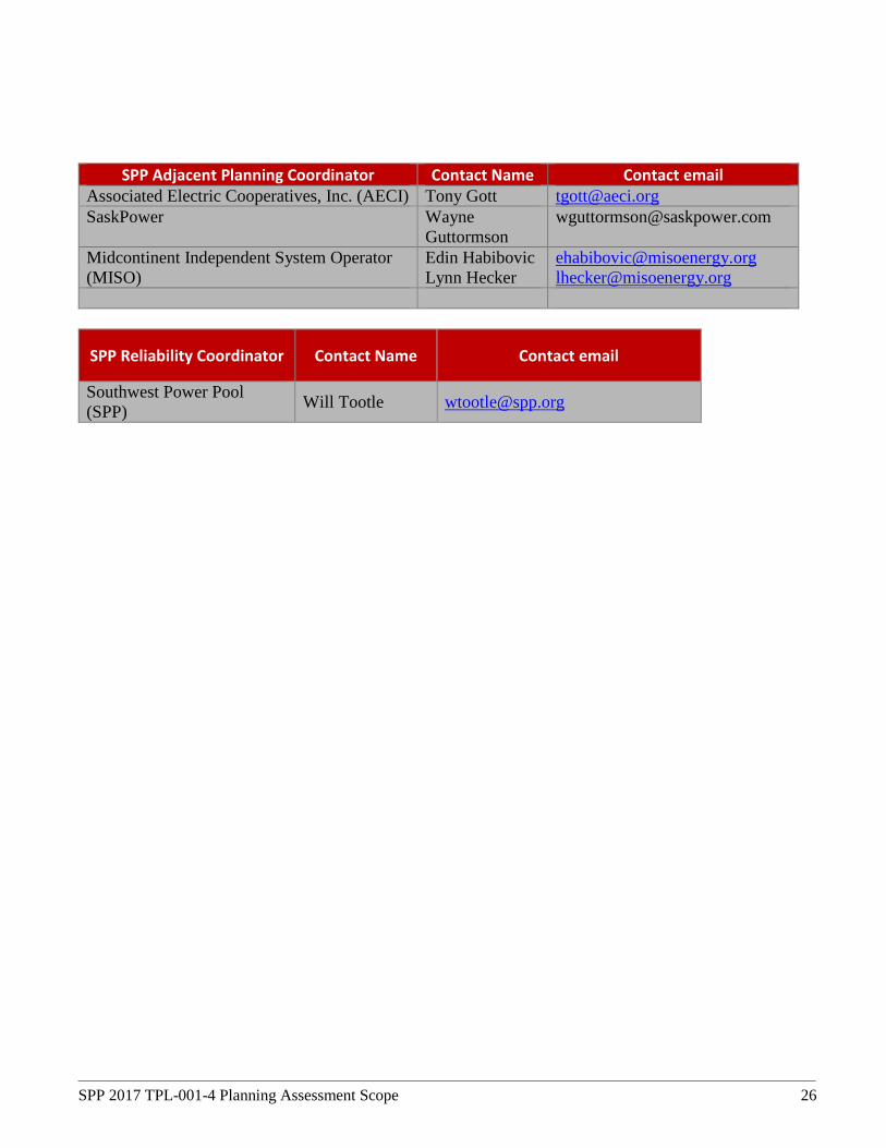
SPP Adjacent Planning Coordinator Contact Name Contact email Associated Electric Cooperatives, Inc. (AECI) Tony Gott [email protected] SaskPower Wayne
Guttormson [email protected]
Midcontinent Independent System Operator (MISO)
Edin Habibovic Lynn Hecker
[email protected] [email protected]
SPP Reliability Coordinator Contact Name Contact email
Southwest Power Pool (SPP) Will Tootle [email protected]

SPP 2017 TPL-001-4 Planning Assessment Scope 27
8. Proposed Schedule for Steady State Analysis

SPP 2017 TPL-001-4 Planning Assessment Scope 28
Owner Scheduled Activities Dates PC Begin Steady State Scope Development January 3 MDWG Contingency data request February 15 PC BES inclusion list and spare equipment data request February 15 PC Company specific Planning criteria request February 15 TWG Scope Approval March 14 MDWG Case Analysis TP Deadline for providing Company specific Planning criteria March 1 MDWG 2017 MDWG Powerflow model set approval March 14 PC Generate MDWG basecase 'P0' potential violations March 15 PC Send TPs MDWG basecase 'P0' potential violations March 21 TP Deadline for providing Contingency data (P1) March 17 TP Deadline for providing 'P0' MDWG basecase CAPs April 4 PC Deadline for applying MDWG basecase CAPs April 11 TP Deadline for providing Contingency data (P2,P4,P5,P7, EE) April 11 TP Deadline for providing BES inclusion list, spare equipment April 11 PC Perform MDWG POM-OPM ACCC runs April 18 PC Organize MDWG POM-OPM ACCC results May 23 PC Send initial potential MDWG violations to TPs/RC and request CAPs July 3 TP Deadline for providing Protection Scheme Contingencies (MDWG) July 12 Sensitivity Case Analysis PC Completion of model build for Sensitivity Models April 14 PC Generate Sensitivity basecase 'P0' potential violations April 18 PC Send TPs Sensitivity basecase 'P0' potential violations April 18 PC Deadline for providing 'P0' Sensitivity basecase CAPs May 6 PC Deadline for applying Sensitivity basecase CAPs May 13 PC Perform Sensitivity POM-OPM ACCC runs May 19 PC Organize Sensitivity POM-OPM ACCC results May 30 PC Send initial potential Sensitivity violations to TPs/RC and request CAPs June 5 TP Deadline for providing Protection Scheme Contingencies (Sensitivity
Case) June 12
TP, RC Deadline for providing CAPs (MDWG and Sensitivity) August 1 PC Complete Testing of CAPs September 1

SPP 2017 TPL-001-4 Planning Assessment Scope 29
9. Proposed Schedule for Stability Analysis
Owner Scheduled Activities Dates TWG Scope Approval March 14 PC Contingency data request (TP and Tier 1 contingencies) April 3 TP Deadline for providing Contingency Data May 15 MDWG Case Analysis MDWG 2016 MDWG Dynamic model set approval September 8 PC Provide Fast Fault Scans Results to TPs October 11 PC Provide Member Submitted Contingency Results to TP/RC for
MDWG models October 16
PC Provide Breaker to Breaker and Tier 1 Contingency Results to TP/RC for MDWG models
October 16
TP Provide input to PC on Fast Fault Scan Results including Corrective Action Plans if necessary
October 25
TP, RC Provide input to PC on Member Submitted Contingency results for MDWG models including Corrective Action Plans if necessary
November 10
TP, RC Provide input to PC on Breaker to Breaker Contingency results for MDWG models including Corrective Action Plans if necessary
November 10
PC Complete testing of CAPs November 20 Sensitivity Case Analysis PC Complete development of Sensitivity models September 25 PC Provide Member Submitted Contingency Results to TP/RC for
Sensitivity models November 1
PC Provide Breaker to Breaker and Tier 1 Contingency Results to TP/RC for Sensitivity models
November 10
TP, RC Provide input to PC on Member Submitted Contingency results for Sensitivity models including Corrective Action Plans if necessary
November 10
TP, RC Provide input to PC on Breaker to Breaker Contingency results for Sensitivity models including Corrective Action Plans if necessary
November 20
PC Complete testing of CAPs November 30

SPP 2017 TPL-001-4 Planning Assessment Scope 30
10. Proposed Schedule for Short Circuit Analysis
Owner Scheduled Activities Dates PC Short Circuit Scope Development January 3 MDWG 2016 MDWG Short circuit model set approval March 14 PC Request ANSI parameters listing of buses for line-out results
using ANSI February 15
TWG TWG Scope Approval March 14 TP Deadline for providing ANSI Fault Current Calculation
parameters and listing of buses for line-out results using ANSI
March 31
PC Perform Short Circuit simulation April 1 PC Send Short Circuit results to TPs and request CAPs July 1 TP Deadline for providing CAPs August 31 PC Complete verification of TP submitted Short Circuit CAPs October 14

SPP 2017 TPL-001-4 Planning Assessment Scope 31
11. Proposed Schedule for Draft Assessment
Owner Scheduled Activities Dates PC Provide Draft Assessment to TWG for review (Steady State
and Short Circuit) November 7
PC Provide Draft Stability Section of Assessment to TWG for review
November 21
TWG Provide feedback to PC pertaining to Draft Assessment December 4 PC Provide Final Assessment for TWG approval December 11 TWG Approval of Final Assessment December 11

SPP 2017 TPL-001-4 Planning Assessment Scope 32
12. Changes in Process and Assumptions
In order to protect against changes in process and assumptions that could present a significant risk to the completion of the TPL study, any such changes must be vetted. If TWG votes on any process steps or assumptions to be used in the study, those assumptions will be used for the 2017 TPL study. Changes to process or assumptions recommended by stakeholders must be approved by the TWG. This process will allow for changes if they are deemed necessary and critical to the TPL study, while also ensuring that changes, and the risks and benefits of those changes, will be fully vetted and discussed.

SPP 2017 TPL-001-4 Planning Assessment Scope 33
Appendix A

SPP 2017 TPL-001-4 Planning Assessment Scope 34
Appendix B
SPP Contingency Naming Convention http://www.spp.org/Documents/28352/SPP%20Contingency%20Naming%20Convention.pdf