Embed Size (px)
Citation preview
1 | P a g e
SPMT BRIDGE MOVE
SAFETY AND CONTINGENCY PLANS
REV 1
Minnesota Department of Transportation
Metro District
Maryland Avenue Bridge Design-Build Project
August 12, 2012
SPMT Safety Plan
1. Only employees engaged in the work will be allowed in the work area.
2. During the lift and move only those employees that are actively engaged
in the work will be allowed to be within 100 feet of the span. Only
critical employees will be allowed on or near the span and SPMT
equipment.
3. Tool box/pre-task meeting will be held with all employees engaged in
the work at the points described below. Tool box meeting will cover the
activities for each crew, risk with their given task, and how the risk will
be controlled. A Lunda Safety Representative will be present for tool
box meetings.
i. Prior to assembling the SPMT.
2 | P a g e
ii. Prior to lifting span 1 and removing the temporary
abutment in the travel path.
iii. Prior to moving Span 1.
iv. As needed to address any safety concerns during the
process.
4. A final walk through pre-move safety meeting will be held 1 hour prior
to lifting the Span 1 and again 1 hour prior to moving Span 1. This will
include walking the travel paths one last time to identify any issues prior
to the move. This meeting will include Lunda Construction, Parsons,
Mammoet, MnDOT, and E&J Steel Erectors.
5. All personnel will be required to wear appropriate PPE including but not
limited to; hard hat, safety shoes, safety glasses, high visibility work
wear, and fall protection equipment as needed.
6. Additional safety concerns.
i. Moving equipment in the work area including SPMT,
cranes, and other wheeled equipment. Educate employees
of struck by accidents and how to prevent them. This will
be done at pre-task and tool box meetings.
ii. Falls from SPMT equipment or spans. All employees
exposed to fall heights over 6 feet will be required to be
protected from that fall through the use of fall protection
including but not limited to handrails, guardrails, tie off, or
manlifts.
7. Key Contacts for decisions during the move.
i. Mammoet – Dennis Theis – SPMT supervisor. Dennis will
be responsible for decisions directly related to the
Operations of SPMT equipment.
ii. Parsons – Steve Haines – SPMT Engineer. Steve will be
responsible for reviewing equipment and travel paths prior
to the lift and moves. Steve will coordinate his review with
Dennis. Steve will also directly supervise twist monitoring
during the move. Steve is responsible for Twist related
issues.
3 | P a g e
iii. Lunda Construction – Dale Even – Project Manager. Dale
will be responsible for overall project coordination during
the lift and moves and will communicate directly with Steve
Haines and Dennis Theis. Dale will communicate with David
Herzog for MnDOT participation. Communications to the
public will be through MnDOT.
iv. Any technical issues during the move will be resolved as
needed between Dennis, Steve, and Dale. The first line of
communication is between Dennis and Steve. Please also
refer to appendix A, section 6 for additional information on
communications.
8. Safety of Spectators and other Industry people will be controlled by
MnDOT and Lunda Construction. All spectators and other interested
industry people will be allowed to view the move from the designated
viewing areas which will be established by MnDOT and Lunda
Construction at a date closer to the move. It is our understanding the
MnDOT will also have a Police presence to help control the area.
9. See appendix A, sections 7 and 9, for additional SPMT specific safety.
SPMT Contingency Plan
1. Travel Path Failure.
a. Review and prove travel path as described in our proposal with a
loaded dump prior to moving the span
b. In the event of a travel path failure we will have labor and equipment
to make repairs including excavating/compaction equipment and
steel plates to bridge any small areas. Recommendations for repairs
will be from Steve Gerber(Geotech). Approval of any required
repairs prior to proceeding will be the responsibility of Dennis Theis.
2. Utility crossings.
a. All utility crossing have been identified. There should be no surprises
here.
b. In the event a utility is damaged during the move, we will notify the
utility owner as soon as damage is identified.
4 | P a g e
3. Weather.
a. In the event of threatening weather, strong storms or high winds, we
will hold off the move until favorable conditions exist. The move
would have to be postponed for lightening, winds above 30 MPH, or
dense fog. The decision to postpone the move will be made by Dale
Even. Project related issues for postponement will be communicated
through Dale Even and Jesten Sterry. Communication for Public
relations will be through David Herzog of MnDOT.
b. Check weather forecast 24 hours, 12 hours and 1 hour prior to move.
4. SPMT Equipment failures.
a. See Appendix A, section 10 for details provided by Mammoet.
5. Span will not fit or cannot set down in final location.
a. In the event for whatever reason the span cannot be positioned as
planned in the final location and corrections cannot be made
immediately (within the allotted closure of 12 hours) the span will be
moved back to the BSA. At this time it will have to be determined if
the span needs to be put back onto falsework. Falsework would have
to re-erected if needed.
6. Twist Limit on Superstructure is reached during move.
a. Please refer to the SPMT Bridge Move Monitoring Plan in
Appendix B.
5 | P a g e
Sap Nr. 0010057233-P154
Doc. Nr. 4000052837-M01-01
Status For Review
Office Mammoet USA South Inc. - Rosharon
20525 FM 521
Rosharon, Texas 77583
USA
Phone 281-369-2200
Fax 281-369-2178
Website www.mammoet.com
Client Lunda Construction
Project Maryland Ave Bridge Replacement
Subject Method Statement with Qualifications – Rev. 01
01 For Review August 9, 2012 WJK
00 For Review April 13, 2012 KHal
Rev. Description Date Ref. Checked
Condition
Method Statement
Client Lunda Construction Sap Nr. 0010057233-P154 Page 2 of 41
Project Maryland Ave Bridge Replacement Doc. Nr. 4000052837-M01-01 Date August 9, 2012
Subject Method Statement and Qualifications Ref. WJK Rev. 01
Office Mammoet USA South Inc. - Rosharon
Status
Method Statement
1 Introduction 4 1.1 Introduction of this manual 4 1.2 General information 4 1.3 Summary of work scope Mammoet 5 1.4 Mammoet Supply Scope 5 1.5 Lunda Supply Scope 5 1.6 Schedule Summary 6 1.7 Bridge Sections Details 6
2 Mobilization 7 2.1 Mammoet Personnel to Site 7 2.2 Unload and Assembly of SPMTs and Jacking Equipment 7
3 Transport Operation 9 3.1 General Transport Arrangements 9 3.2 Installation of the New Bridge Spans 9
4 Site-data 10 4.1 Bridge Replacement Operation Location 10
5 Weather conditions 11 5.1 Termination Criteria 12 5.2 Power / Transmission - Failure Procedure 12
6 Communications 14
7 Transport Safety 15 7.1 Pre-movement checklist 15
8 Equipment outline specifications 18 8.1 Self Propelled Modular Transporters 18
9 Safety Expectations 20 9.1 Site Orientation 20
Contents
Client Lunda Construction Sap Nr. 0010057233-P154 Page 3 of 41
Project Maryland Ave Bridge Replacement Doc. Nr. 4000052837-M01-01 Date August 9, 2012
Subject Method Statement and Qualifications Ref. WJK Rev. 01
Office Mammoet USA South Inc. - Rosharon
Status
Method Statement
9.2 Mammoet Safety Policies 20 9.3 Equipment safety 21 9.4 Mammoet standard site safety regulations 23 9.4.1 Scope 23 Before work commences 23 9.4.2 Whilst working on site 24 9.4.3 At completion of work 24 9.4.4 Employee’s responsibility 24 9.4.5 Relation between Mammoet and any sub-contractors (including union employees otherwise not
familiar with Mammoet practices) 25
10 Risk Analysis and Contingency Plans 26
11 Reference Projects 34
12 Appendix – Personnel Resumes 41 12.1 Dennis Theis 41 12.2 Craig White 41 12.3 Alfred Cox 41 12.4 Eddie Arroyo 41
Client Lunda Construction Sap Nr. 0010057233-P154 Page 4 of 41
Project Maryland Ave Bridge Replacement Doc. Nr. 4000052837-M01-01 Date August 9, 2012
Subject Method Statement and Qualifications Ref. WJK Rev. 01
Office Mammoet USA South Inc. - Rosharon
Status
Method Statement
1 Introduction
1.1 Introduction of this manual
The purpose of this document is to provide engineering and planning data to enable the safe installation of the new bridge
segment and to verify that all reasonable considerations have been taken. Additionally, personnel resumes, equipment
specifications and Mammoet’s qualifications are provided. The Installation Operation is the responsibility of the fabricator
who will sublet key elements of the work to Mammoet. This document has been originated by Mammoet and refers
essentially to their work scope on the new Maryland Ave bridge spans (2) over Interstate 35E in St. Paul, MN.
1.2 General information
Maryland Ave Bridge Sections
Lunda Construction has appointed MAMMOET as Transport Operation contractor for the above-mentioned Project.
COMPANY INFORMATION
Lunda Construction
Contact Email Cell Role
Dale Even [email protected] 651-775-7206 Project Manager
Jess Sterry [email protected] 651-325-6845 Project Engineer
Mammoet
Contact Email Cell Role
JR Gonzalez [email protected] 281-914-2183 Project Manager
Alfonso Martin [email protected] 832-291-4930 Project Engineer
Michael Willenborg [email protected] 281-914-2138 Engineering Manager
Piet Nooren [email protected] 281-733-4999 Technical Director
Client Lunda Construction Sap Nr. 0010057233-P154 Page 5 of 41
Project Maryland Ave Bridge Replacement Doc. Nr. 4000052837-M01-01 Date August 9, 2012
Subject Method Statement and Qualifications Ref. WJK Rev. 01
Office Mammoet USA South Inc. - Rosharon
Status
Method Statement
1.3 Summary of work scope Mammoet
• Engineering of the transport methods
• Mobilization and demobilization
• The Transport of the new bridge section from false work to the final position on the bridge bents.
• The handling and assembly of the SPMTs and related cribbing.
• The securing of the bridge sections to the transport system.
1.4 Mammoet Supply Scope
Supply of personnel to include:
• 1 supervisor
• 2 SPMT operators
• 4 Mammoet riggers
• Transport, board and lodging for Mammoet personnel.
Supply of major equipment, including:
• 88 lines of SPMT’s with 4 Power packs
• Cribbing, stands and steel mats
• Chain and cable lashings as required
• Mammoet Mega Jacks
• Climbing Jacks
1.5 Lunda Supply Scope
Supply of major equipment, including:
• 90T crane(min) with riggers and operators to assist with Mammoet equipment unloading
• Forklift or extendable boom forklift for loading and unloading and setup
• Safety instruction / introduction to Mammoet crew directly after their arrival at site
• Supply of adequate staging area and travel zone with compacted soil
• Traffic control and police assistance
• Sufficient clearance to move the bridge sections into place
• Appropriate lighting during night time work hours if and when needed
• Removal of street furniture where applicable
Client Lunda Construction Sap Nr. 0010057233-P154 Page 6 of 41
Project Maryland Ave Bridge Replacement Doc. Nr. 4000052837-M01-01 Date August 9, 2012
Subject Method Statement and Qualifications Ref. WJK Rev. 01
Office Mammoet USA South Inc. - Rosharon
Status
Method Statement
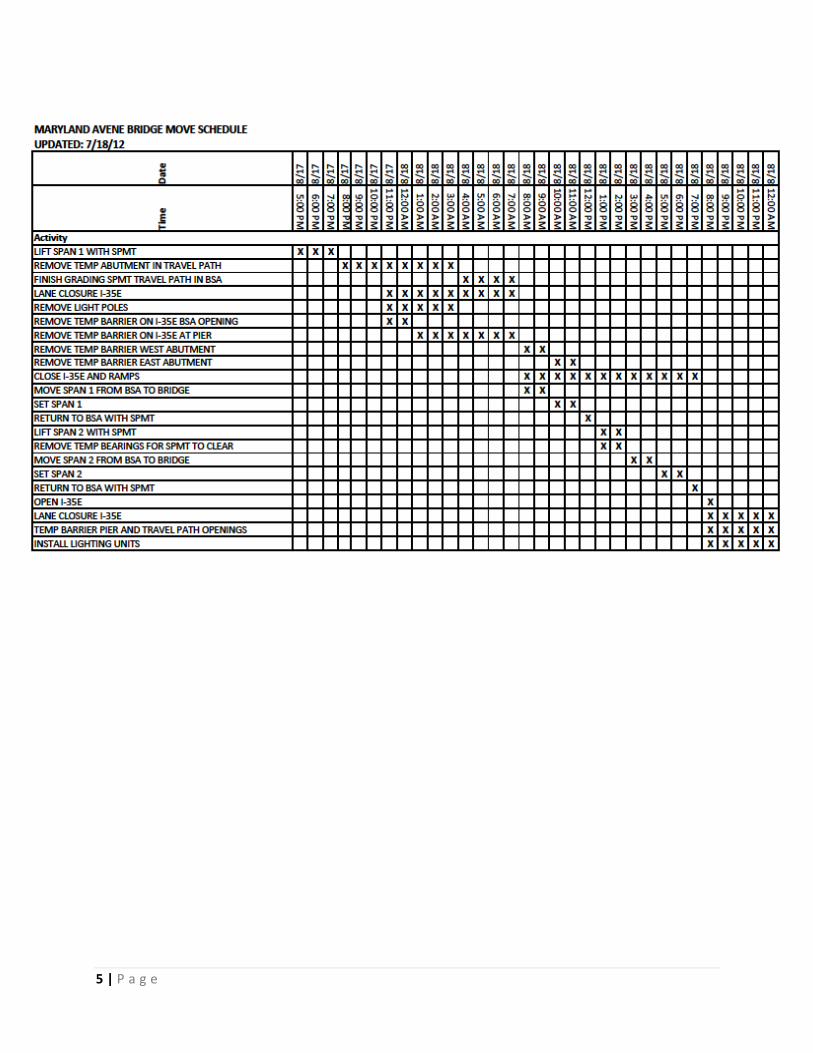
1.6 Schedule Summary
For time consideration, the bridge installation operation will be carried out by means of Self Propelled Modular
Transporters (SPMTs) fitted with a combination of Mammoet Megajacks and climbing jack systems. This setup will lessen
the reconfiguration time required from the first bridge panel to the second. Mammoet has been given a 12 hour window for
placement of the bridge spans. The following is an estimated schedule.
Event Day Description
Mobilization of crew Day 0 The crew will arrive the night before
the work is to begin.
Site specific orientation
Equipment mobilization
Equipment assembly
Day 1 The equipment will be offloaded,
assembled and tested. This time will
be used to correct any planning
issues.
Equipment placement
Test lift/test drive
Contingent day for site preparation
Day 2 The configured SPMTs will be
positioned under the first bridge span,
test lift the bridge span/test drive the
bridge span. This time will be used to
correct any issues with the operation.
Bridge span installations* Day 3 Bridge spans will be installed.
Equipment demobilization Day 4 Equipment will be disassembled and
loaded for shipping.
*Bridge spans will only be moved with MNDOT and client approval.
1.7 Bridge Sections Details
The heaviest (new) bridge section is estimated to weigh 1,363 Ton [2,720,000 lbs].
New Bridge Weight
120’ wide x 100’ long 1363 tons (2,726,000 lbs)
Client Lunda Construction Sap Nr. 0010057233-P154 Page 7 of 41
Project Maryland Ave Bridge Replacement Doc. Nr. 4000052837-M01-01 Date August 9, 2012
Subject Method Statement and Qualifications Ref. WJK Rev. 01
Office Mammoet USA South Inc. - Rosharon
Status
Method Statement
2 Mobilization
2.1 Mammoet Personnel to Site
Mammoet will provide approximately 7 personnel during the peak of the operation. A maximum Mammoet
presence of 6 days from setup to demobilization will be anticipated. Mammoet personnel will arrive the night
before and plan on receiving a site orientation from the Lunda site H&S officer before the start of work. Any
required site specific training or PPE shall be conveyed ahead of time to expedite the operation.
2.2 Unload and Assembly of SPMTs and Jacking Equipment
Mammoet will use flatbeds and stepdeck trailers to mobilize its equipment to site. The SPMTs come in units of
4 and 6 lines. Mammoet will ask Lunda Construction to provide a crane with a minimum capacity of 90 tons to
unload the trailers. Each SPMT unit will be off-loaded using 4 slings of sufficient capacity to off-load the
trailers and the powerpacks.
After off-loading the first SPMT unit, the crane will lift the powerpack off the truck and install it behind the unit.
The connection between the powerpack and the SPMT will be made with two bolts and one hydraulic operated
pin. Hydraulic hoses with couplings will provide the connection between the powerpack and the SPMT. Once
this connection is accomplished, the unit is operational and will be used to couple the other units. The crane
will lift the next unit of the trailer and lower it on the ground. The SPMT unit with the powerpack will line up with
this unit and the connection between the two units will be installed. This connection consists of one
hydraulically operated pin, 4 bolts and a number of hydraulic hoses.
To couple SPMTs sideways, special coupling blocks will be bolted to the side of one SPMT unit. This unit will
then be driven next to another unit, lined up and adjusted in height. The other side of the coupling block will
then be connected with bolts to the other SPMT. If necessary, hydraulic hoses will be installed between the
two units. The timeframe necessary to connect one SPMT unit to the next is roughly half an hour. However
the total duration depends largely on the arrival of the trucks.
Once both sets of trailers are ready, the crane or an extendable boom forklift will place the transport beams
across both sets of double SPMTs. At this time the SPMTs will be connected electrically. The computer in the
SPMT will be programmed to make sure all units will work as one and can be operated by one man.
Client Lunda Construction Sap Nr. 0010057233-P154 Page 8 of 41
Project Maryland Ave Bridge Replacement Doc. Nr. 4000052837-M01-01 Date August 9, 2012
Subject Method Statement and Qualifications Ref. WJK Rev. 01
Office Mammoet USA South Inc. - Rosharon
Status
Method Statement
In the meantime the exact location of the climbing jacks and Megajacks will be determined by measuring down
the length of the trailers using the center line of the trailers as a reference point. The dimensions from
drawing: 0010057233-P154-D-T01 will be used.
Approx. 4 or 5 layers of 4”X 4” hardwood timbers of 3.5 ft length will be stacked in the required pattern for the
climbing jacks. The climbing jacks will be placed on top using an extendable boom forklift and the hydraulic
hoses connected to the climbing jack powerpack. The climbing jack powerpack will be located on the SPMT
with the climbing jack assemblies. Once the climbing jacks are installed, the steel mats will be placed on top
and secured to the climbing jack tops via welded clips.
The next step will be to drive the trailers under the first of the prefabricated spans and position them in their
correct locations. The units will need to be lined out exactly to ensure no problems during the transport of the
spans. Chains and binders will be installed securing the SPMTs to the first new bridge span.
The Mega jacks have lashing points that will serve as connection points when lashing the bridge span. See
lashing lines on Drawing: 0010057233-P154-D-T01.
Client Lunda Construction Sap Nr. 0010057233-P154 Page 9 of 41
Project Maryland Ave Bridge Replacement Doc. Nr. 4000052837-M01-01 Date August 9, 2012
Subject Method Statement and Qualifications Ref. WJK Rev. 01
Office Mammoet USA South Inc. - Rosharon
Status
Method Statement
3 Transport Operation
3.1 General Transport Arrangements
It is assumed that the old bridge spans will be removed and the piers prepared to accept the new bridge spans
prior to Mammoet’s work scope is to begin. Mammoet will mobilize its personnel on August 12, 2012. The
necessary Mammoet equipment will begin to arrive to site on Day 1: August 13th for assembly prior to the
bridge Installation operation. Day 3: Mammoet will use two trains of SPMTs to move the new spans into place.
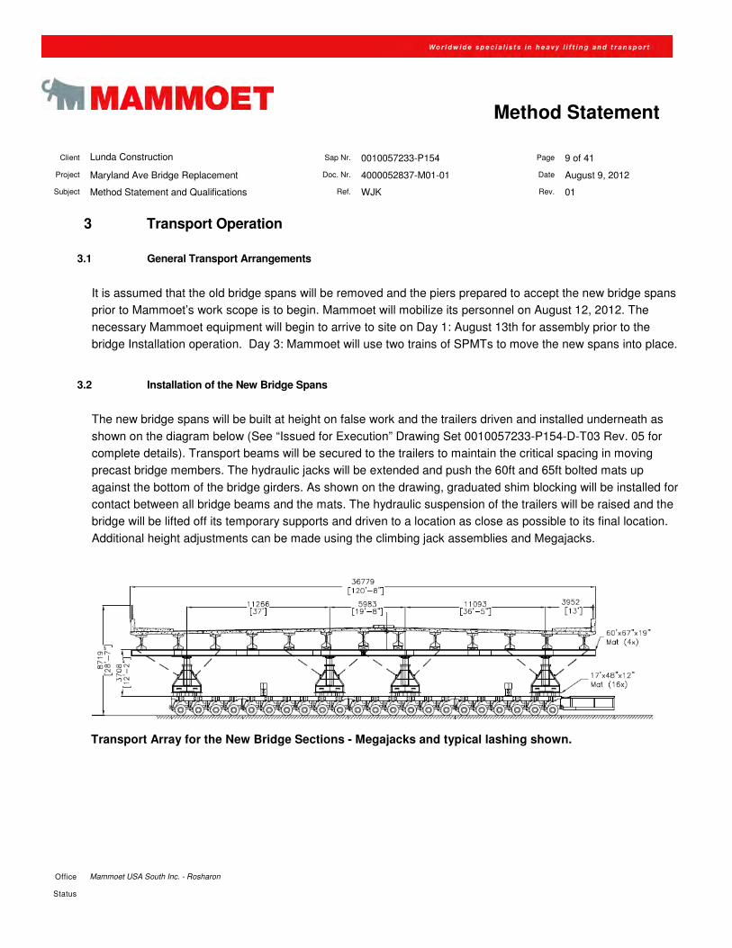
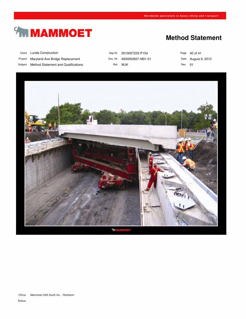
3.2 Installation of the New Bridge Spans
The new bridge spans will be built at height on false work and the trailers driven and installed underneath as
shown on the diagram below (See “Issued for Execution” Drawing Set 0010057233-P154-D-T03 Rev. 05 for
complete details). Transport beams will be secured to the trailers to maintain the critical spacing in moving
precast bridge members. The hydraulic jacks will be extended and push the 60ft and 65ft bolted mats up
against the bottom of the bridge girders. As shown on the drawing, graduated shim blocking will be installed for
contact between all bridge beams and the mats. The hydraulic suspension of the trailers will be raised and the
bridge will be lifted off its temporary supports and driven to a location as close as possible to its final location.
Additional height adjustments can be made using the climbing jack assemblies and Megajacks.
Transport Array for the New Bridge Sections - Megajacks and typical lashing shown.
Client Lunda Construction Sap Nr. 0010057233-P154 Page 10 of 41
Project Maryland Ave Bridge Replacement Doc. Nr. 4000052837-M01-01 Date August 9, 2012
Subject Method Statement and Qualifications Ref. WJK Rev. 01
Office Mammoet USA South Inc. - Rosharon
Status
Method Statement
4 Site-data
4.1 Bridge Replacement Operation Location
Lunda Construction’s site is located on the southwest side of the intersection of Maryland Ave (Hwy 31) and Interstate 35E
(Hwy 10) in St Paul, MN. The spans will be constructed at or near installation height in the orientation for which they will be
installed. The current plan is to break the concrete hwy divider to allow one set of SPMTs to travel north bound lanes while
the other travels the south bound lanes with the transport spanning over the concrete divider.
Client Lunda Construction Sap Nr. 0010057233-P154 Page 11 of 41
Project Maryland Ave Bridge Replacement Doc. Nr. 4000052837-M01-01 Date August 9, 2012
Subject Method Statement and Qualifications Ref. WJK Rev. 01
Office Mammoet USA South Inc. - Rosharon
Status
Method Statement
5 Weather conditions
The construction manager will establish a weather report prior to the transport operations, in accordance with
the jacking/transport requirements from Mammoet.
In general the transport operation shall not proceed unless a weather report forecasting suitable conditions for
a minimum of twenty-four hours or three times the operation period whichever is the greatest, has been
received.
Prior to the start of the transport operation, Lunda Construction will be consulted regarding the decision
whether to proceed with the operation or to postpone it due to weather conditions or other restrictions.
A maximum wind criteria for starting the Bridge Installation Operation is proposed to be Wind-force 6
(Beaufort) and decreasing. Stability calculations have been based on these criteria. In addition, a minimum
visibility of 100m is required.
Wind-force Wind Speed Wind Speed Wind speed Wind Speed Pressure Pressure
Beaufort Knots miles / h Km / h m / s kg/m2 Te/m
2
3 7 – 10 12,1 19.4 5,4 1,9 0,002
4 11 – 16 17,7 28.4 7,9 4,0 0,004
5 17 – 21 23,9 38.5 10,7 7,3 0,007
6 22 – 27 30,9 49.7 13,8 12,1 0,012
7 28 – 33 38,3 61.6 17,1 18,6 0,019
8 34 – 40 46,3 74.5 20,7 27,3 0,027
9 41 – 47 54,6 87.8 24,4 37,9 0,038
10 48 – 55 63,5 102.2 28,4 51,4 0,051
11 56 – 65 73,0 117.4 32,6 67,7 0,068
12 65 +
Client Lunda Construction Sap Nr. 0010057233-P154 Page 12 of 41
Project Maryland Ave Bridge Replacement Doc. Nr. 4000052837-M01-01 Date August 9, 2012
Subject Method Statement and Qualifications Ref. WJK Rev. 01
Office Mammoet USA South Inc. - Rosharon
Status
Method Statement
5.1 Termination Criteria
Decisions on whether to postpone or terminate a transport operation may have to be taken at any time prior to
a transport operation commencing or during the transport operation.
PRIOR TO TRANSPORT OPERATION COMMENCING
A Transport operation will be postponed if one of the following conditions applies:
• If any significant item of the transport equipment becomes defective
• If any data relating to the trailers is found to be significantly at variance with the loading calculations,
drawings or transport operation procedures
• If the weather conditions are found to be significantly worse than those predicted.
AFTER TRANSPORT OPERATION HAS COMMENCED
There can be no absolute rules for determining at what stage a transport operation would be "aborted" or
"continued with" following technical problems arising once the transport operation has commenced. In the
event of a serious problem or delay occurring, then a joint decision, whether to proceed or pull back, would be
taken by Lunda Construction and Mammoet, based on the following general guide lines.
5.2 Power / Transmission - Failure Procedure
Unlike conventional transport systems, which may rely on external power units (tractor units, winches,
hydraulic jacks, etc.), the power source for a Mammoet self-propelled modular transporter is entirely self-
contained. Equipment specifications can be found in Section 8 of this manual, but he details can be
summarized as follows:
� Propulsion is obtained from hydrostatic motors, which are located within the “drive” axles of a 4-line or
6-line unit. The 4-line unit has 2 motors while the 6-line unit has 4 motors. Once hydraulic pressure is
delivered, each motor produces torque, which when transferred to the ground, equals a horizontal
force of 5.5 tonnes. As such, a 6-line unit can transmit a horizontal force of 22.0 tonnes.
Should a transmission fault occur in any individual drive unit, the drive can be disengaged simply, without
removing any wheel or releasing any of the payload. This is accomplished by turning a screw which has a
direct internal connection and acts as a clutch to isolate the drive mechanism.
Client Lunda Construction Sap Nr. 0010057233-P154 Page 13 of 41
Project Maryland Ave Bridge Replacement Doc. Nr. 4000052837-M01-01 Date August 9, 2012
Subject Method Statement and Qualifications Ref. WJK Rev. 01
Office Mammoet USA South Inc. - Rosharon
Status
Method Statement
The power pack units, which are mounted to the rear of each trailer unit, supply "constant" pressure to the
hydrostatic drive units. In the event of a power pack failure, the remaining functioning power packs have
additional capacity and fittings, which can be easily connected to the affected trailer, allowing the transport to
proceed. Although pressure can be maintained, the flow rate of hydraulic fluid is reduced. The result is
horizontal force with a reduced travel speed.
Client Lunda Construction Sap Nr. 0010057233-P154 Page 14 of 41
Project Maryland Ave Bridge Replacement Doc. Nr. 4000052837-M01-01 Date August 9, 2012
Subject Method Statement and Qualifications Ref. WJK Rev. 01
Office Mammoet USA South Inc. - Rosharon
Status
Method Statement
6 Communications
A radio can be furnished by Mammoet to Lunda’s construction manager to communicate critical or emergency
information. However, it is mandatory that communication (other than emergency information) during transport
and associated operations is limited to Mammoet personnel (which will include Steve Haines). Otherwise,
verbal communication is recommended during critical tasks. Outside communication shall be relayed through
designated Lunda personnel. Designated Lunda representatives shall be responsible for communicating
status updates, problems, postponement, resolutions, etc.
Communications among Mammoet operators and transport supervision will be by radio, unless there is local
interference, on our nationally licensed frequencies. All other communication will be verbal; face to face or
by mobile phone.
Communications among Mammoet personnel during operations will be in English, on one of the frequencies
listed below. Mammoet radios are equipped with a “Tone Lock” which will keep any interference from other
frequencies to a minimum.
• Frequency 1 - Transmit/receive 464.50000 MHz.
• Frequency 2 - Transmit/receive 464.55000 MHz.
• Frequency 3 - Transmit/receive 464.60000 MHz.
• Frequency 4 - Transmit/receive 464.70000 MHz.
• Frequency 5 - Transmit/receive 469.50000 MHz.
• Frequency 6 - Transmit/receive 469.55000 MHz.
• Frequency 7 - Transmit/receive 469.60000 MHz.
• Frequency 8 - Transmit/receive 469.70000 MHz.
• Call Sign – WPLR953
Client Lunda Construction Sap Nr. 0010057233-P154 Page 15 of 41
Project Maryland Ave Bridge Replacement Doc. Nr. 4000052837-M01-01 Date August 9, 2012
Subject Method Statement and Qualifications Ref. WJK Rev. 01
Office Mammoet USA South Inc. - Rosharon
Status
Method Statement
7 Transport Safety
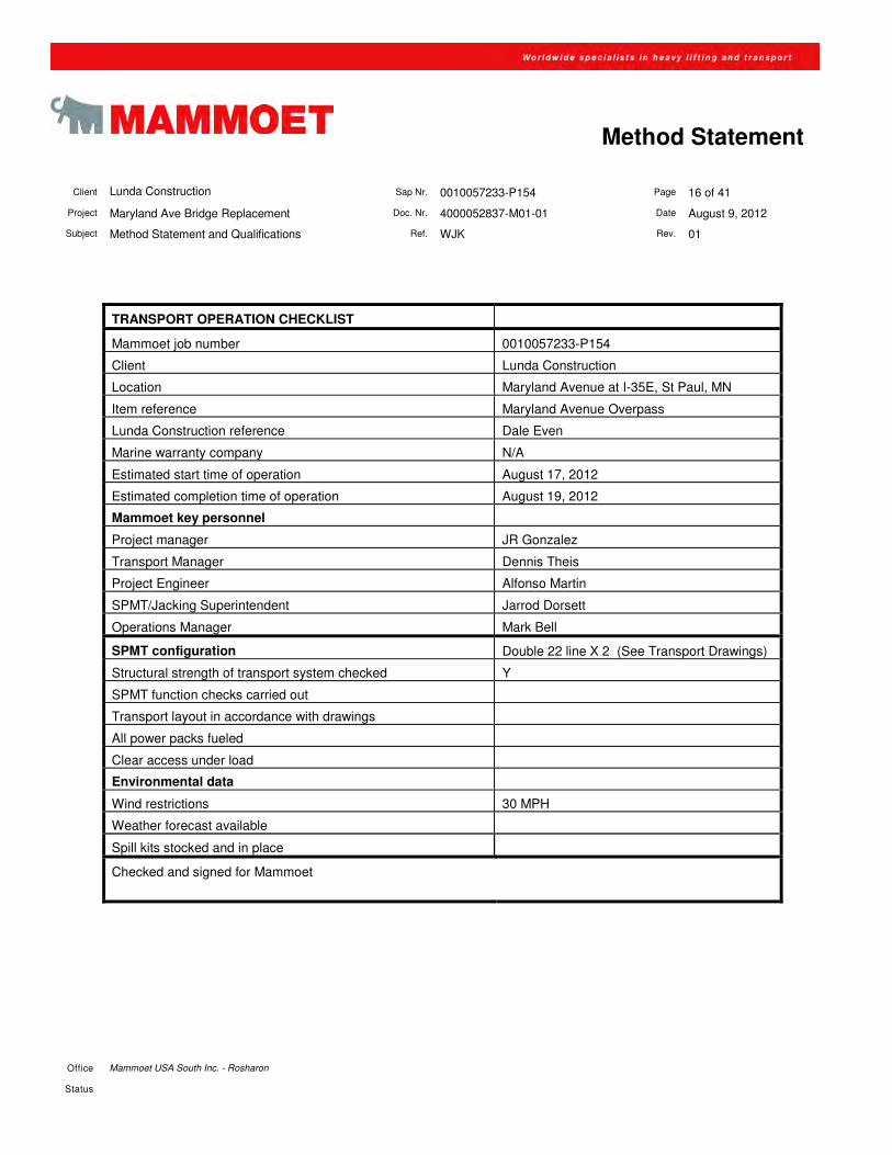
7.1 Pre-movement checklist
In order to ensure that all operations are carried out in accordance with approved and engineered procedures,
Mammoet personnel on site will complete a checklist as the equipment is assembled and tested. For this
operation the following points will be checked:
• The trailer assembly is in accordance with transport drawings
• The trailer drive system is functioning in forward and reverse
• All steering functions are available and operable
• Trailer computer co-ordinates are input and verified
• The hydraulic lifting system is fully pressurized and leak tested
• Diesel levels in the power pack are adequate for the operation
• Hydraulic fluid in the reservoir tank is within operating limits
• Access under the bridge panels is suitable and the transport route is clear
In addition to the above checks, which are carried out before lifting the load, the following are verified:
• All operations personnel fully briefed on operating conditions
• Radios fully charged and working
• After lifting ensure that pressures are within safe limits
• Lunda Construction will be notified of readiness to move
• Local weather conditions checked, to ensure they are not going to cause danger to the load or
operating personnel
Only when the above are found to be acceptable, along with the approval of all calculations and the method
statement, should Lunda Construction allow the transport operation to commence. The checklist shall be
signed by the transport supervisor and reviewed with the Lunda construction manager.
Client Lunda Construction Sap Nr. 0010057233-P154 Page 16 of 41
Project Maryland Ave Bridge Replacement Doc. Nr. 4000052837-M01-01 Date August 9, 2012
Subject Method Statement and Qualifications Ref. WJK Rev. 01
Office Mammoet USA South Inc. - Rosharon
Status
Method Statement
TRANSPORT OPERATION CHECKLIST
Mammoet job number 0010057233-P154
Client Lunda Construction
Location Maryland Avenue at I-35E, St Paul, MN
Item reference Maryland Avenue Overpass
Lunda Construction reference Dale Even
Marine warranty company N/A
Estimated start time of operation August 17, 2012
Estimated completion time of operation August 19, 2012
Mammoet key personnel
Project manager JR Gonzalez
Transport Manager Dennis Theis
Project Engineer Alfonso Martin
SPMT/Jacking Superintendent Jarrod Dorsett
Operations Manager Mark Bell
SPMT configuration Double 22 line X 2 (See Transport Drawings)
Structural strength of transport system checked Y
SPMT function checks carried out
Transport layout in accordance with drawings
All power packs fueled
Clear access under load
Environmental data
Wind restrictions 30 MPH
Weather forecast available
Spill kits stocked and in place
Checked and signed for Mammoet
Client Lunda Construction Sap Nr. 0010057233-P154 Page 17 of 41
Project Maryland Ave Bridge Replacement Doc. Nr. 4000052837-M01-01 Date August 9, 2012
Subject Method Statement and Qualifications Ref. WJK Rev. 01
Office Mammoet USA South Inc. - Rosharon
Status
Method Statement
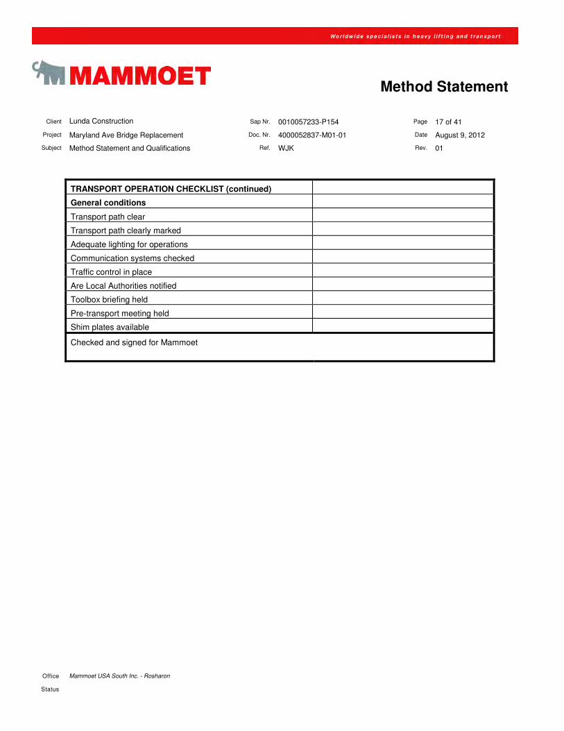
TRANSPORT OPERATION CHECKLIST (continued)
General conditions
Transport path clear
Transport path clearly marked
Adequate lighting for operations
Communication systems checked
Traffic control in place
Are Local Authorities notified
Toolbox briefing held
Pre-transport meeting held
Shim plates available
Checked and signed for Mammoet
Client Lunda Construction Sap Nr. 0010057233-P154 Page 18 of 41
Project Maryland Ave Bridge Replacement Doc. Nr. 4000052837-M01-01 Date August 9, 2012
Subject Method Statement and Qualifications Ref. WJK Rev. 01
Office Mammoet USA South Inc. - Rosharon
Status
Method Statement
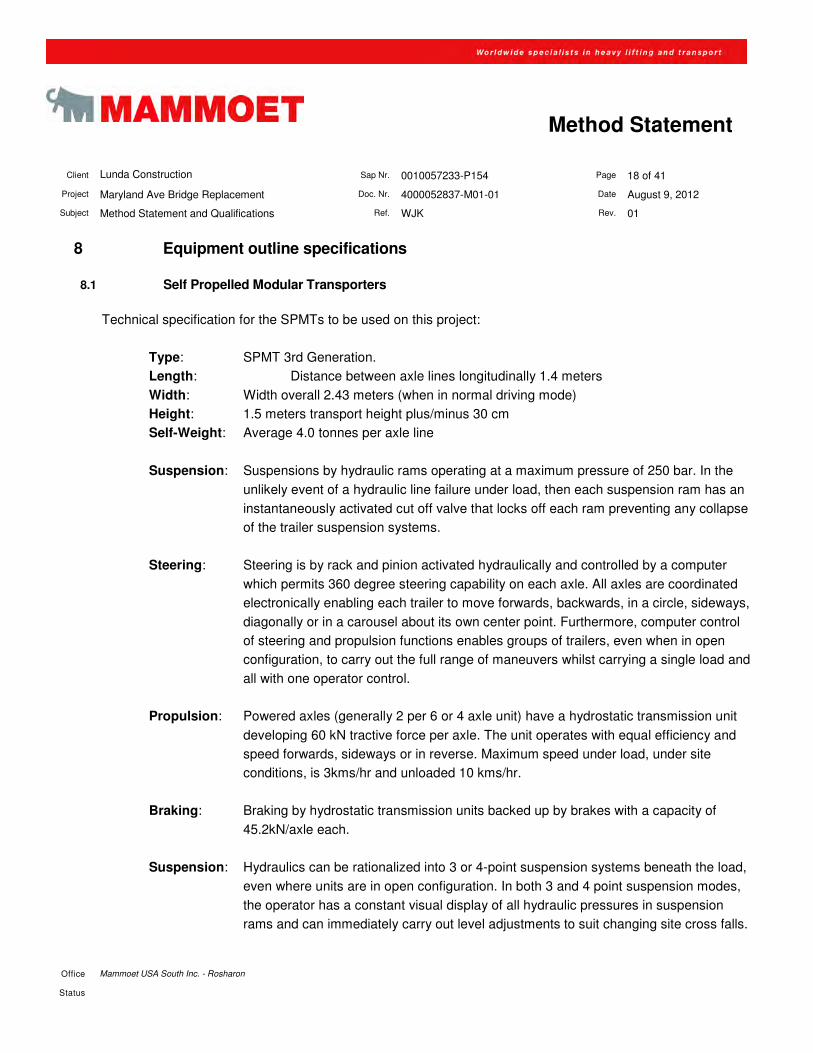
8 Equipment outline specifications
8.1 Self Propelled Modular Transporters
Technical specification for the SPMTs to be used on this project:
Type: SPMT 3rd Generation.
Length: Distance between axle lines longitudinally 1.4 meters
Width: Width overall 2.43 meters (when in normal driving mode)
Height: 1.5 meters transport height plus/minus 30 cm
Self-Weight: Average 4.0 tonnes per axle line
Suspension: Suspensions by hydraulic rams operating at a maximum pressure of 250 bar. In the
unlikely event of a hydraulic line failure under load, then each suspension ram has an
instantaneously activated cut off valve that locks off each ram preventing any collapse
of the trailer suspension systems.
Steering: Steering is by rack and pinion activated hydraulically and controlled by a computer
which permits 360 degree steering capability on each axle. All axles are coordinated
electronically enabling each trailer to move forwards, backwards, in a circle, sideways,
diagonally or in a carousel about its own center point. Furthermore, computer control
of steering and propulsion functions enables groups of trailers, even when in open
configuration, to carry out the full range of maneuvers whilst carrying a single load and
all with one operator control.
Propulsion: Powered axles (generally 2 per 6 or 4 axle unit) have a hydrostatic transmission unit
developing 60 kN tractive force per axle. The unit operates with equal efficiency and
speed forwards, sideways or in reverse. Maximum speed under load, under site
conditions, is 3kms/hr and unloaded 10 kms/hr.
Braking: Braking by hydrostatic transmission units backed up by brakes with a capacity of
45.2kN/axle each.
Suspension: Hydraulics can be rationalized into 3 or 4-point suspension systems beneath the load,
even where units are in open configuration. In both 3 and 4 point suspension modes,
the operator has a constant visual display of all hydraulic pressures in suspension
rams and can immediately carry out level adjustments to suit changing site cross falls.
Client Lunda Construction Sap Nr. 0010057233-P154 Page 19 of 41
Project Maryland Ave Bridge Replacement Doc. Nr. 4000052837-M01-01 Date August 9, 2012
Subject Method Statement and Qualifications Ref. WJK Rev. 01
Office Mammoet USA South Inc. - Rosharon
Status
Method Statement
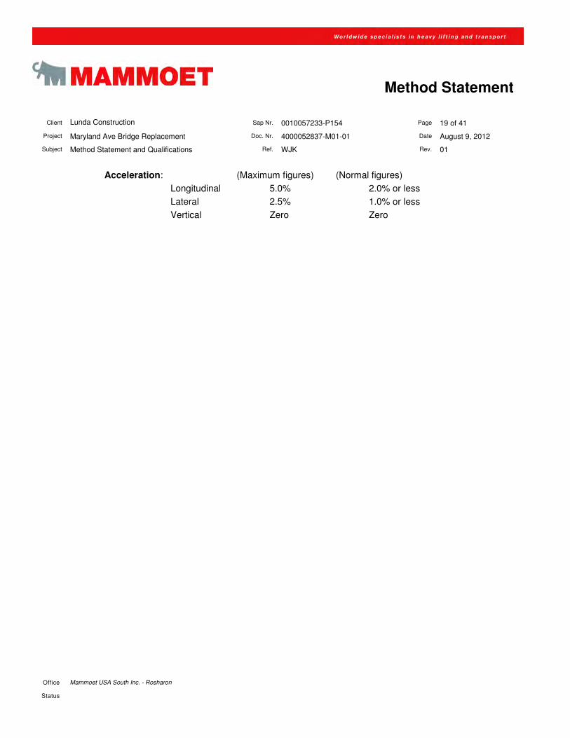
Acceleration: (Maximum figures) (Normal figures)
Longitudinal 5.0% 2.0% or less
Lateral 2.5% 1.0% or less
Vertical Zero Zero
Client Lunda Construction Sap Nr. 0010057233-P154 Page 20 of 41
Project Maryland Ave Bridge Replacement Doc. Nr. 4000052837-M01-01 Date August 9, 2012
Subject Method Statement and Qualifications Ref. WJK Rev. 01
Office Mammoet USA South Inc. - Rosharon
Status
Method Statement
9 Safety Expectations
9.1 Site Orientation
The safety officer for Lunda Construction will instruct Mammoet employees directly upon mobilization to site.
Mammoet employees will be made familiar with site rules and regulations.
During Mammoet’s site operations and transport, the BSA and travel area will be restricted. There will be a
“RESTRICTED” perimeter which will be limited Mammoet and Lunda Construction employees directly involved
with Mammoet operations. Beyond the “RESTRICTED” perimeter shall be a “LIMITED ACCESS” perimeter,
which will be limited to designated members of the project task force and MnDOT. We recommend that
attendance by members / employees of applicable companies, agencies, etc. is monitored and controlled from
within.
9.2 Mammoet Safety Policies
Before each operation a toolbox meeting will be held where the involved people are instructed.
It is the policy of Mammoet USA that the safety and health of its employees and those of its Sub-contractors is
of prime importance in all activities of the Company.
The policy is intended to minimize, and if possible, prevent, all avoidable accidents and hazards to health.
Mammoet USA, as employer, accepts that it is primarily responsible for the health and safety of it's employees
and that it should prepare procedures for carrying out all activities in which it operates, as well as providing
adequate supervision to ensure that safe procedures are correctly executed, however, Mammoet also expects
it's employees to be responsible for their own actions and informs them regularly of the risks and dangers than
can be met and expects them to be involved in the preparation of safe working procedures.
Mammoet will arrange for periodic visits to be made to all site establishments by the Mammoet Group Safety
Officer. Notwithstanding these visits, all Mammoet employees are encouraged to think "safety" at all times and
to notify management of any areas where safety procedures require improvement.
It is the policy of the Company that every employee must wear protective clothing as appropriate to the activity
being carried out and that persistent refusal of the employee to do so is likely to result in dismissal.
Client Lunda Construction Sap Nr. 0010057233-P154 Page 21 of 41
Project Maryland Ave Bridge Replacement Doc. Nr. 4000052837-M01-01 Date August 9, 2012
Subject Method Statement and Qualifications Ref. WJK Rev. 01
Office Mammoet USA South Inc. - Rosharon
Status
Method Statement
To ensure that this policy is actively carried out, the Company accepts that it is responsible for instructing it's
employees of safe procedures for carrying out all activities and to give further instruction if additional
employees are recruited, or if the nature of activities change, or if the location of activities demand additional
knowledge or regulations to be complied with.
In the event of an unsafe or dangerous occurrence taking place, (whether or not this causes injury) then this
must be fully recorded, investigated and action taken to ensure that any repetition is avoided.
It is the policy of Mammoet that all levels of management are required to enforce this policy statement and that
any examples of unsafe activities shall be notified and investigated by the Managing Director of the Company,
who is ultimately responsible for safety within the group.
9.3 Equipment safety
Mammoet has a high record of safety established over many years of experience. The following additional
features are incorporated into Mammoet's self-propelled modular transporters.
A single operator controls all steering and propulsion functions, even where trailers are in open configuration.
Misunderstanding and poor co-ordination between operators cannot occur.
Steering is computer controlled, even where trailers are separated in open configuration. This prevents
horizontal forces being induced into the structure even where complex turning maneuvers are carried out.
Every suspension is fitted with a safety valve, which cuts off instantaneously in the event of hose failure and
prevents suspension collapse.
Fully reversible hydrostatic motors enable 'pull back' to be carried out any stage, if site conditions demand.
Easily disengaged half shafts in power axles enable movement to continue in the unlikely event of power pack
failure occurring during movement.
In the unprecedented situation of 2 power packs malfunctioning at the same time, then the spare ports on
remaining power pack allow the connection of hydraulic power hoses to be fed to defective transporters
allowing movement to continue (but at a slower speed).
The single operator has a continuous visual display of all suspension pressures, whether a 3 point or 4 point
suspension system is in use.
Client Lunda Construction Sap Nr. 0010057233-P154 Page 22 of 41
Project Maryland Ave Bridge Replacement Doc. Nr. 4000052837-M01-01 Date August 9, 2012
Subject Method Statement and Qualifications Ref. WJK Rev. 01
Office Mammoet USA South Inc. - Rosharon
Status
Method Statement
All systems have a mechanical over-ride in the event of a serious malfunction of the electronic controls
occurring.
Client Lunda Construction Sap Nr. 0010057233-P154 Page 23 of 41
Project Maryland Ave Bridge Replacement Doc. Nr. 4000052837-M01-01 Date August 9, 2012
Subject Method Statement and Qualifications Ref. WJK Rev. 01
Office Mammoet USA South Inc. - Rosharon
Status
Method Statement
9.4 Mammoet standard site safety regulations
Mammoet’s objective connected to safety is to recognize and consider safety as an essential ingredient of good
management and efficient workmanship. It is established on site as a matter of normal discipline.
It is the Company's policy to make all staff, supervisors and hourly paid staff fully aware of basic safety requirements.
9.4.1 Scope
These rules apply to the management, supervision and entire workforce of Mammoet, together with its sub-contractors in
terms of general safety.
PROJECT MANAGER
At all times it must be recognized that the Project Manager is the person who is directly responsible for the protection of the
men/women in his charge, and that the responsibility is not lessened by the presence of a Safety Officer in the
organization.
SUPERVISOR
Supervisors apply the safety rules and procedures. Instructing new employees and making random safety inspections in
their areas of responsibility and taking prompt actions when deemed necessary.
SAFETY OFFICER
The safety officer is responsible for the overall safety during all operations. The safety officer will have a day-to-day
responsibility to ensure that the health and safety arrangements are being applied effectively. He will also be responsible
for the marking/confirming of the restricted area during the site-move and assembly operation.
Before work commences
• Arrange supplies of goggles, safety helmets and other protective equipment, which is deemed necessary.
• Consider site conditions, possible obstructions and other hazards, which may be detrimental to safety and health.
• Personnel should be made familiar with:
o Location of Emergency Medical Center
o First Aid positions and MSDS Right to Know Binder location,
o Procedures to obtain emergency services,
o Rules governing evacuation of site,
o Fire drill procedure on site.
• To ensure Mammoet and sub-contractor personnel attend all Lunda Construction induction courses accordingly.
Client Lunda Construction Sap Nr. 0010057233-P154 Page 24 of 41
Project Maryland Ave Bridge Replacement Doc. Nr. 4000052837-M01-01 Date August 9, 2012
Subject Method Statement and Qualifications Ref. WJK Rev. 01
Office Mammoet USA South Inc. - Rosharon
Status
Method Statement
9.4.2 Whilst working on site
• Ensure that health and safety regulations are observed, e.g. the wearing of protective clothing, suitable boots,
glasses, etc.
• Monitor the work of all personnel and stimulate their interest and involvement in safety. Red Mammoet issue
coveralls will not be worn on this site, alternate coveralls such as Mammoet kaki will be worn.
• Orange reflective vests will be worn by all persons while on site.
• Lace up work boots with minimum 6” height, safety reinforced toes, and minimum ½” high defined heel.
• Periodically inspect equipment, statutory site records (if requested), notices and general tidiness.
• Good housekeeping is a watchword. Any untidy site is more likely to be unsafe.
• Investigate all accidents leading to injury, damage or loss.
• In the event of an accident, take any immediate action necessary to deal with the situation.
• Ensure only competent and authorized personnel use site plant and equipment.
9.4.3 At completion of work
• Ensure that any statutory records, which Lunda Construction requires, are correctly completed and handed over.
9.4.4 Employee’s responsibility
• Comply with all statutory regulations.
• Work in a safe manner.
• Report to your immediate supervisor all unsafe conditions that arise.
• Report all incidents that may lead to accidents or injury.
• Comply with all rules and regulations made by MNDOT and Lunda Construction with regard to safety on site.
• Co-operate with the management in accident investigation.
• Employees are encouraged to take part in all schemes, which promote an interest in safety.
• Keep working areas clean and tidy.
• Safety helmets must be worn at all times in construction areas.
• Make use of all safety equipment and protective clothing that is available where circumstances require it.
• Inspect your equipment prior to use, if faulty report to your supervisor immediately.
• Where a hazard has to be created, it is important that warning signs are displayed and action taken to prevent
injury.
• If you damage equipment or tackle, report it to your supervisor immediately. Damaged equipment leads to
accidents.
• All injuries received during the course of your employment on site must be recorded in the Accident Prevention
Book and reported to the company Safety Officer.
Client Lunda Construction Sap Nr. 0010057233-P154 Page 25 of 41
Project Maryland Ave Bridge Replacement Doc. Nr. 4000052837-M01-01 Date August 9, 2012
Subject Method Statement and Qualifications Ref. WJK Rev. 01
Office Mammoet USA South Inc. - Rosharon
Status
Method Statement
9.4.5 Relation between Mammoet and any sub-contractors (including union employees otherwise not familiar with
Mammoet practices)
• The sub-contractor manager is responsible to the Mammoet supervisor for the implementation of all safety rules
and regulations connected with sub-contractors/suppliers.
• Sub-contractors staff assigned to site are required to ensure within their particular areas of responsibility that rules
and regulations are observed.
• Sub-contractors managers are responsible for making available the information necessary to allow their
employees to carry out their work safely.
• This is affected through training, job instruction and safety supervision.
• Protective clothing and equipment must be made readily available and instructions given concerning its use by
sub-contractors.
• Mammoet management has the responsibility to ensure that sub-contractors receive all Lunda Construction safety
rules relevant to their undertakings and issue directives necessary in accordance with Lunda Construction’s safe
working procedures.
• Sub-contractors are required to ensure that their employees are properly trained, given all information relevant to
the working environment.
• Sub-contractors shall fully comply with the Mammoet safety standards, instructions and safe working procedures
and any additional safety information issued by Lunda Construction.
• Sub-contractors must provide their employees with and ensure they are worn, whenever statutory or
site regulations prescribe, the following minimum requirements of personal protection equipment:
Safety helmets, Safety boots, Safety glasses; all specific to above listed requirements.
Client Lunda Construction Sap Nr. 0010057233-P154 Page 26 of 41
Project Maryland Ave Bridge Replacement Doc. Nr. 4000052837-M01-01 Date August 9, 2012
Subject Method Statement and Qualifications Ref. WJK Rev. 01
Office Mammoet USA South Inc. - Rosharon
Status
Method Statement
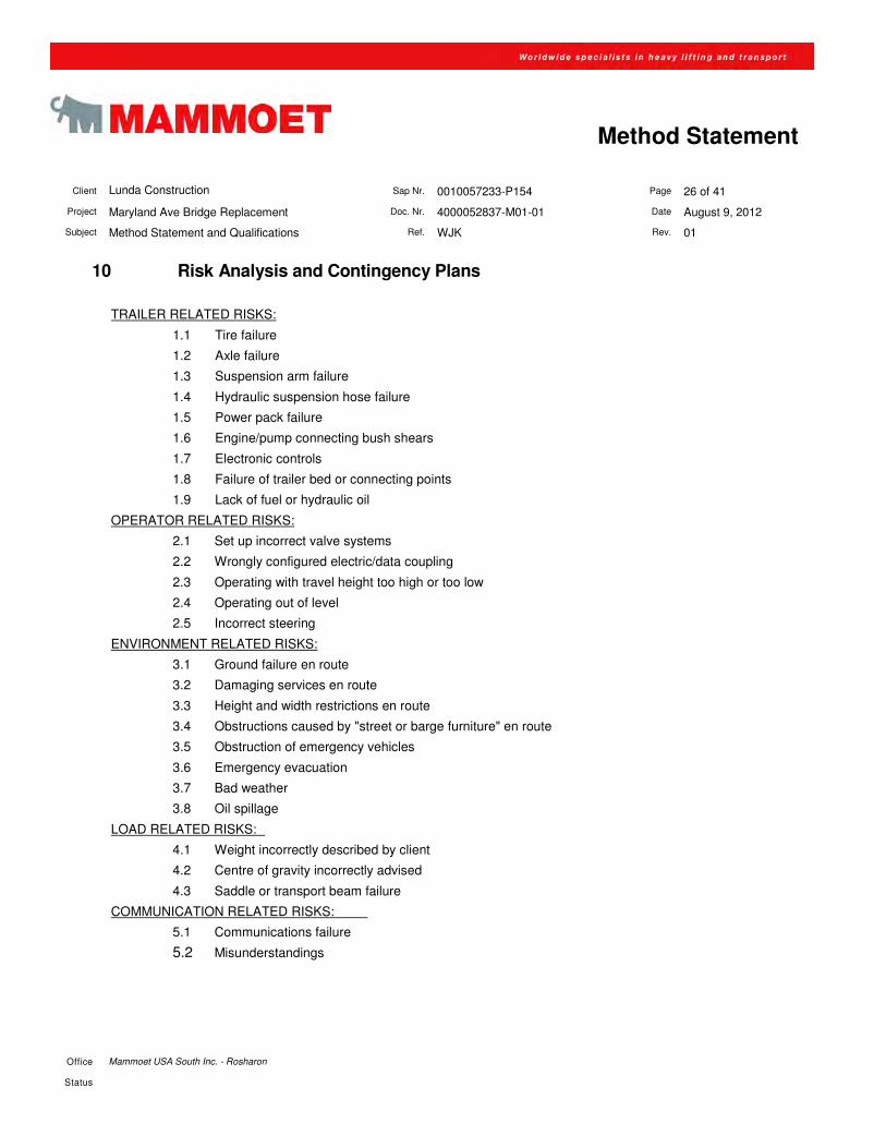
10 Risk Analysis and Contingency Plans
TRAILER RELATED RISKS:
1.1 Tire failure
1.2 Axle failure
1.3 Suspension arm failure
1.4 Hydraulic suspension hose failure
1.5 Power pack failure
1.6 Engine/pump connecting bush shears
1.7 Electronic controls
1.8 Failure of trailer bed or connecting points
1.9 Lack of fuel or hydraulic oil
OPERATOR RELATED RISKS:
2.1 Set up incorrect valve systems
2.2 Wrongly configured electric/data coupling
2.3 Operating with travel height too high or too low
2.4 Operating out of level
2.5 Incorrect steering
ENVIRONMENT RELATED RISKS:
3.1 Ground failure en route
3.2 Damaging services en route
3.3 Height and width restrictions en route
3.4 Obstructions caused by "street or barge furniture" en route
3.5 Obstruction of emergency vehicles
3.6 Emergency evacuation
3.7 Bad weather
3.8 Oil spillage
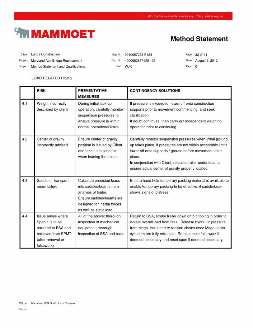
LOAD RELATED RISKS:
4.1 Weight incorrectly described by client
4.2 Centre of gravity incorrectly advised
4.3 Saddle or transport beam failure
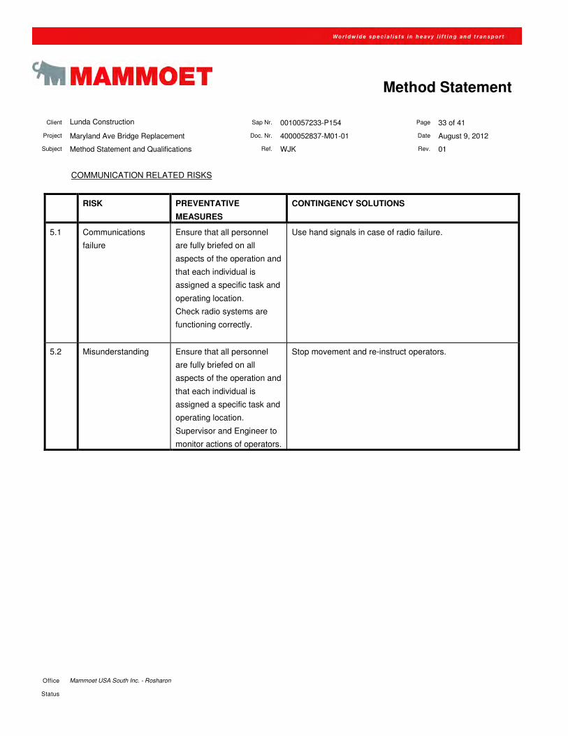
COMMUNICATION RELATED RISKS: 5.1 Communications failure
5.2 Misunderstandings
Client Lunda Construction Sap Nr. 0010057233-P154 Page 27 of 41
Project Maryland Ave Bridge Replacement Doc. Nr. 4000052837-M01-01 Date August 9, 2012
Subject Method Statement and Qualifications Ref. WJK Rev. 01
Office Mammoet USA South Inc. - Rosharon
Status
Method Statement
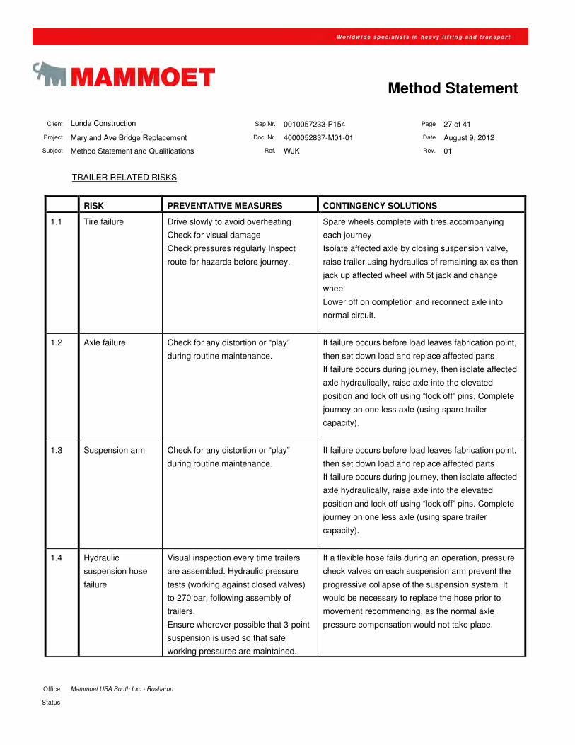
TRAILER RELATED RISKS
RISK PREVENTATIVE MEASURES CONTINGENCY SOLUTIONS
1.1 Tire failure Drive slowly to avoid overheating
Check for visual damage
Check pressures regularly Inspect
route for hazards before journey.
Spare wheels complete with tires accompanying
each journey
Isolate affected axle by closing suspension valve,
raise trailer using hydraulics of remaining axles then
jack up affected wheel with 5t jack and change
wheel
Lower off on completion and reconnect axle into
normal circuit.
1.2
Axle failure Check for any distortion or “play”
during routine maintenance.
If failure occurs before load leaves fabrication point,
then set down load and replace affected parts
If failure occurs during journey, then isolate affected
axle hydraulically, raise axle into the elevated
position and lock off using “lock off” pins. Complete
journey on one less axle (using spare trailer
capacity).
1.3 Suspension arm Check for any distortion or “play”
during routine maintenance.
If failure occurs before load leaves fabrication point,
then set down load and replace affected parts
If failure occurs during journey, then isolate affected
axle hydraulically, raise axle into the elevated
position and lock off using “lock off” pins. Complete
journey on one less axle (using spare trailer
capacity).
1.4 Hydraulic
suspension hose
failure
Visual inspection every time trailers
are assembled. Hydraulic pressure
tests (working against closed valves)
to 270 bar, following assembly of
trailers.
Ensure wherever possible that 3-point
suspension is used so that safe
working pressures are maintained.
If a flexible hose fails during an operation, pressure
check valves on each suspension arm prevent the
progressive collapse of the suspension system. It
would be necessary to replace the hose prior to
movement recommencing, as the normal axle
pressure compensation would not take place.
Client Lunda Construction Sap Nr. 0010057233-P154 Page 28 of 41
Project Maryland Ave Bridge Replacement Doc. Nr. 4000052837-M01-01 Date August 9, 2012
Subject Method Statement and Qualifications Ref. WJK Rev. 01
Office Mammoet USA South Inc. - Rosharon
Status
Method Statement
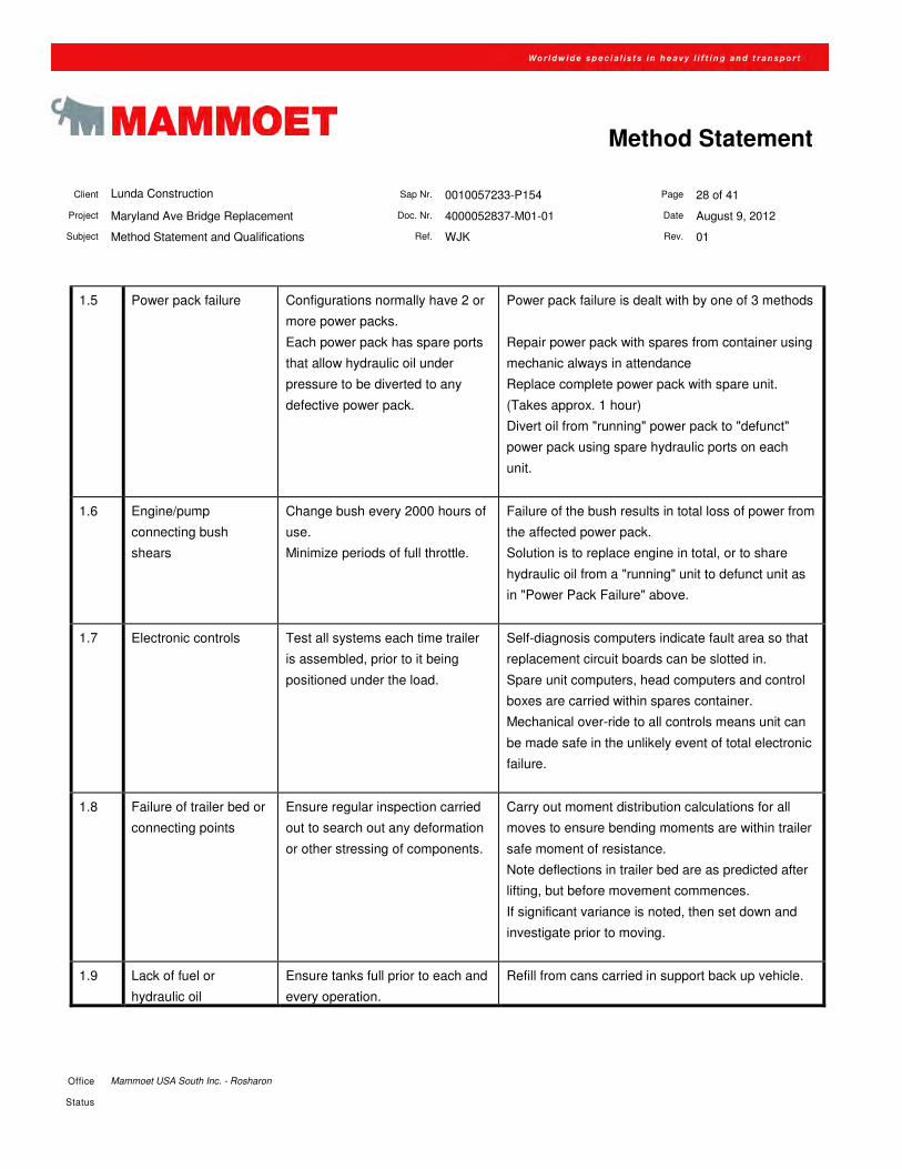
1.5 Power pack failure Configurations normally have 2 or
more power packs.
Each power pack has spare ports
that allow hydraulic oil under
pressure to be diverted to any
defective power pack.
Power pack failure is dealt with by one of 3 methods
Repair power pack with spares from container using
mechanic always in attendance
Replace complete power pack with spare unit.
(Takes approx. 1 hour)
Divert oil from "running" power pack to "defunct"
power pack using spare hydraulic ports on each
unit.
1.6 Engine/pump
connecting bush
shears
Change bush every 2000 hours of
use.
Minimize periods of full throttle.
Failure of the bush results in total loss of power from
the affected power pack.
Solution is to replace engine in total, or to share
hydraulic oil from a "running" unit to defunct unit as
in "Power Pack Failure" above.
1.7 Electronic controls Test all systems each time trailer
is assembled, prior to it being
positioned under the load.
Self-diagnosis computers indicate fault area so that
replacement circuit boards can be slotted in.
Spare unit computers, head computers and control
boxes are carried within spares container.
Mechanical over-ride to all controls means unit can
be made safe in the unlikely event of total electronic
failure.
1.8 Failure of trailer bed or
connecting points
Ensure regular inspection carried
out to search out any deformation
or other stressing of components.
Carry out moment distribution calculations for all
moves to ensure bending moments are within trailer
safe moment of resistance.
Note deflections in trailer bed are as predicted after
lifting, but before movement commences.
If significant variance is noted, then set down and
investigate prior to moving.
1.9 Lack of fuel or
hydraulic oil
Ensure tanks full prior to each and
every operation.
Refill from cans carried in support back up vehicle.
Client Lunda Construction Sap Nr. 0010057233-P154 Page 29 of 41
Project Maryland Ave Bridge Replacement Doc. Nr. 4000052837-M01-01 Date August 9, 2012
Subject Method Statement and Qualifications Ref. WJK Rev. 01
Office Mammoet USA South Inc. - Rosharon
Status
Method Statement
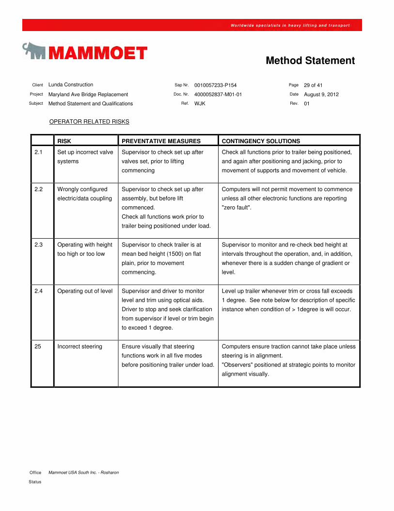
OPERATOR RELATED RISKS
RISK PREVENTATIVE MEASURES CONTINGENCY SOLUTIONS
2.1 Set up incorrect valve
systems
Supervisor to check set up after
valves set, prior to lifting
commencing
Check all functions prior to trailer being positioned,
and again after positioning and jacking, prior to
movement of supports and movement of vehicle.
2.2 Wrongly configured
electric/data coupling
Supervisor to check set up after
assembly, but before lift
commenced.
Check all functions work prior to
trailer being positioned under load.
Computers will not permit movement to commence
unless all other electronic functions are reporting
"zero fault".
2.3 Operating with height
too high or too low
Supervisor to check trailer is at
mean bed height (1500) on flat
plain, prior to movement
commencing.
Supervisor to monitor and re-check bed height at
intervals throughout the operation, and, in addition,
whenever there is a sudden change of gradient or
level.
2.4 Operating out of level Supervisor and driver to monitor
level and trim using optical aids.
Driver to stop and seek clarification
from supervisor if level or trim begin
to exceed 1 degree.
Level up trailer whenever trim or cross fall exceeds
1 degree. See note below for description of specific
instance when condition of > 1degree is will occur.
25 Incorrect steering Ensure visually that steering
functions work in all five modes
before positioning trailer under load.
Computers ensure traction cannot take place unless
steering is in alignment.
"Observers" positioned at strategic points to monitor
alignment visually.
Client Lunda Construction Sap Nr. 0010057233-P154 Page 30 of 41
Project Maryland Ave Bridge Replacement Doc. Nr. 4000052837-M01-01 Date August 9, 2012
Subject Method Statement and Qualifications Ref. WJK Rev. 01
Office Mammoet USA South Inc. - Rosharon
Status
Method Statement
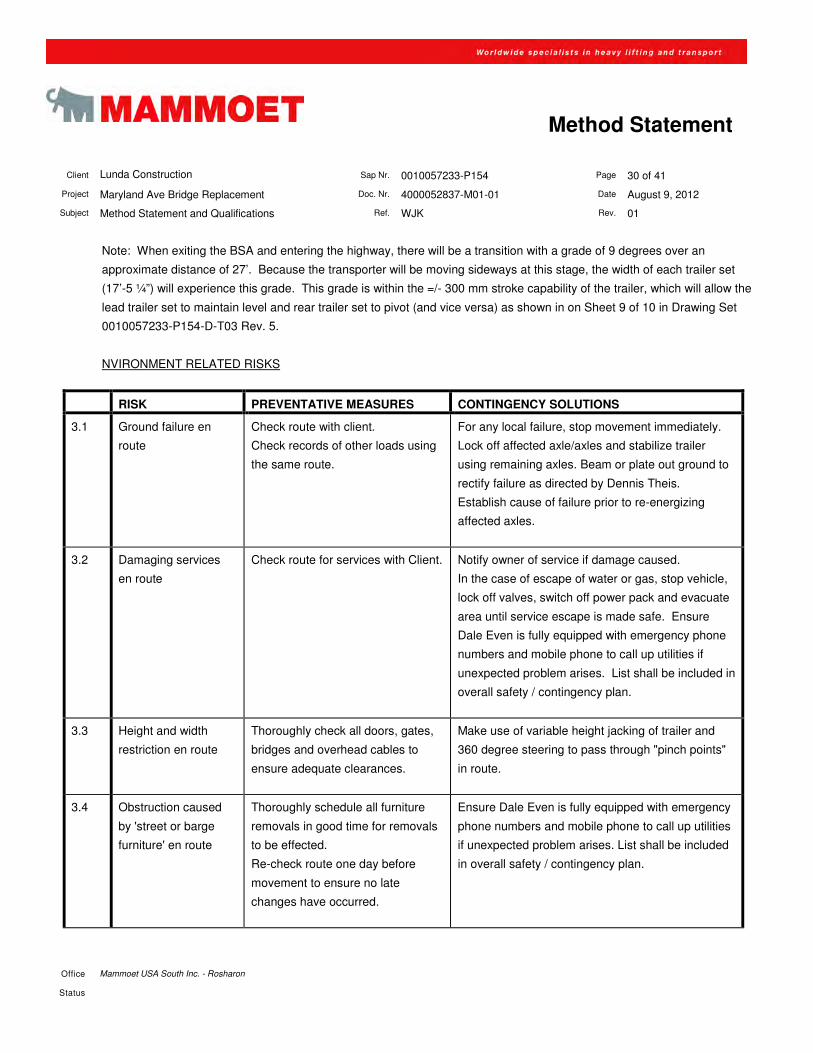
Note: When exiting the BSA and entering the highway, there will be a transition with a grade of 9 degrees over an
approximate distance of 27’. Because the transporter will be moving sideways at this stage, the width of each trailer set
(17’-5 ¼”) will experience this grade. This grade is within the =/- 300 mm stroke capability of the trailer, which will allow the
lead trailer set to maintain level and rear trailer set to pivot (and vice versa) as shown in on Sheet 9 of 10 in Drawing Set
0010057233-P154-D-T03 Rev. 5.
NVIRONMENT RELATED RISKS
RISK PREVENTATIVE MEASURES CONTINGENCY SOLUTIONS
3.1 Ground failure en
route
Check route with client.
Check records of other loads using
the same route.
For any local failure, stop movement immediately.
Lock off affected axle/axles and stabilize trailer
using remaining axles. Beam or plate out ground to
rectify failure as directed by Dennis Theis.
Establish cause of failure prior to re-energizing
affected axles.
3.2 Damaging services
en route
Check route for services with Client. Notify owner of service if damage caused.
In the case of escape of water or gas, stop vehicle,
lock off valves, switch off power pack and evacuate
area until service escape is made safe. Ensure
Dale Even is fully equipped with emergency phone
numbers and mobile phone to call up utilities if
unexpected problem arises. List shall be included in
overall safety / contingency plan.
3.3 Height and width
restriction en route
Thoroughly check all doors, gates,
bridges and overhead cables to
ensure adequate clearances.
Make use of variable height jacking of trailer and
360 degree steering to pass through "pinch points"
in route.
3.4 Obstruction caused
by 'street or barge
furniture' en route
Thoroughly schedule all furniture
removals in good time for removals
to be effected.
Re-check route one day before
movement to ensure no late
changes have occurred.
Ensure Dale Even is fully equipped with emergency
phone numbers and mobile phone to call up utilities
if unexpected problem arises. List shall be included
in overall safety / contingency plan.
Client Lunda Construction Sap Nr. 0010057233-P154 Page 31 of 41
Project Maryland Ave Bridge Replacement Doc. Nr. 4000052837-M01-01 Date August 9, 2012
Subject Method Statement and Qualifications Ref. WJK Rev. 01
Office Mammoet USA South Inc. - Rosharon
Status
Method Statement
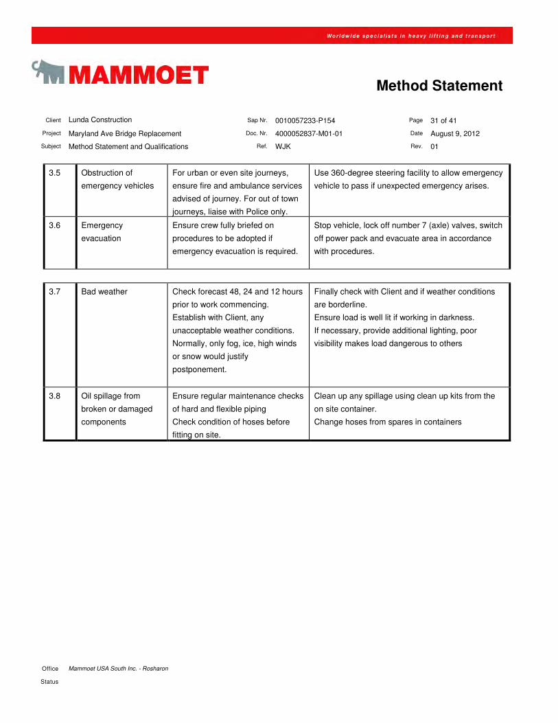
3.5 Obstruction of
emergency vehicles
For urban or even site journeys,
ensure fire and ambulance services
advised of journey. For out of town
journeys, liaise with Police only.
Use 360-degree steering facility to allow emergency
vehicle to pass if unexpected emergency arises.
3.6 Emergency
evacuation
Ensure crew fully briefed on
procedures to be adopted if
emergency evacuation is required.
Stop vehicle, lock off number 7 (axle) valves, switch
off power pack and evacuate area in accordance
with procedures.
3.7 Bad weather Check forecast 48, 24 and 12 hours
prior to work commencing.
Establish with Client, any
unacceptable weather conditions.
Normally, only fog, ice, high winds
or snow would justify
postponement.
Finally check with Client and if weather conditions
are borderline.
Ensure load is well lit if working in darkness.
If necessary, provide additional lighting, poor
visibility makes load dangerous to others
3.8 Oil spillage from
broken or damaged
components
Ensure regular maintenance checks
of hard and flexible piping
Check condition of hoses before
fitting on site.
Clean up any spillage using clean up kits from the
on site container.
Change hoses from spares in containers
Client Lunda Construction Sap Nr. 0010057233-P154 Page 32 of 41
Project Maryland Ave Bridge Replacement Doc. Nr. 4000052837-M01-01 Date August 9, 2012
Subject Method Statement and Qualifications Ref. WJK Rev. 01
Office Mammoet USA South Inc. - Rosharon
Status
Method Statement
LOAD RELATED RISKS
RISK PREVENTATIVE
MEASURES
CONTINGENCY SOLUTIONS
4.1 Weight incorrectly
described by client
During initial jack up
operation, carefully monitor
suspension pressures to
ensure pressure is within
normal operational limits.
If pressure is exceeded, lower off onto construction
supports prior to movement commencing, and seek
clarification.
If doubt continues, then carry out independent weighing
operation prior to continuing
4.2 Center of gravity
incorrectly advised
Ensure center of gravity
position is issued by Client
and taken into account
when loading the trailer.
Carefully monitor suspension pressures when initial jacking
up takes place. If pressures are not within acceptable limits,
lower off onto supports / ground before movement takes
place.
In conjunction with Client, relocate trailer under load to
ensure actual center of gravity properly located.
4.3 Saddle or transport
beam failure
Calculate predicted loads
into saddles/beams from
analysis of trailer.
Ensure saddles/beams are
designed for inertia forces
as well as static load.
Ensure hand held temporary packing material is available to
enable temporary packing to be effective, if saddle/beam
shows signs of distress.
4.4 Issue arises where
Span 1 is to be
returned to BSA and
removed from SPMT
(after removal or
falsework)
All of the above; thorough
inspection of mechanical
equipment; thorough
inspection of BSA and route
Return to BSA, stroke trailer down onto cribbing in order to
isolate overall load from tires. Release hydraulic pressure
from Mega Jacks and re-tension chains once Mega Jacks
cylinders are fully retracted. Re-assemble falsework if
deemed necessary and reset span if deemed necessary.
Client Lunda Construction Sap Nr. 0010057233-P154 Page 33 of 41
Project Maryland Ave Bridge Replacement Doc. Nr. 4000052837-M01-01 Date August 9, 2012
Subject Method Statement and Qualifications Ref. WJK Rev. 01
Office Mammoet USA South Inc. - Rosharon
Status
Method Statement
COMMUNICATION RELATED RISKS
RISK PREVENTATIVE
MEASURES
CONTINGENCY SOLUTIONS
5.1 Communications
failure
Ensure that all personnel
are fully briefed on all
aspects of the operation and
that each individual is
assigned a specific task and
operating location.
Check radio systems are
functioning correctly.
Use hand signals in case of radio failure.
5.2 Misunderstanding Ensure that all personnel
are fully briefed on all
aspects of the operation and
that each individual is
assigned a specific task and
operating location.
Supervisor and Engineer to
monitor actions of operators.
Stop movement and re-instruct operators.
Client Lunda Construction Sap Nr. 0010057233-P154 Page 34 of 41
Project Maryland Ave Bridge Replacement Doc. Nr. 4000052837-M01-01 Date August 9, 2012
Subject Method Statement and Qualifications Ref. WJK Rev. 01
Office Mammoet USA South Inc. - Rosharon
Status
Method Statement
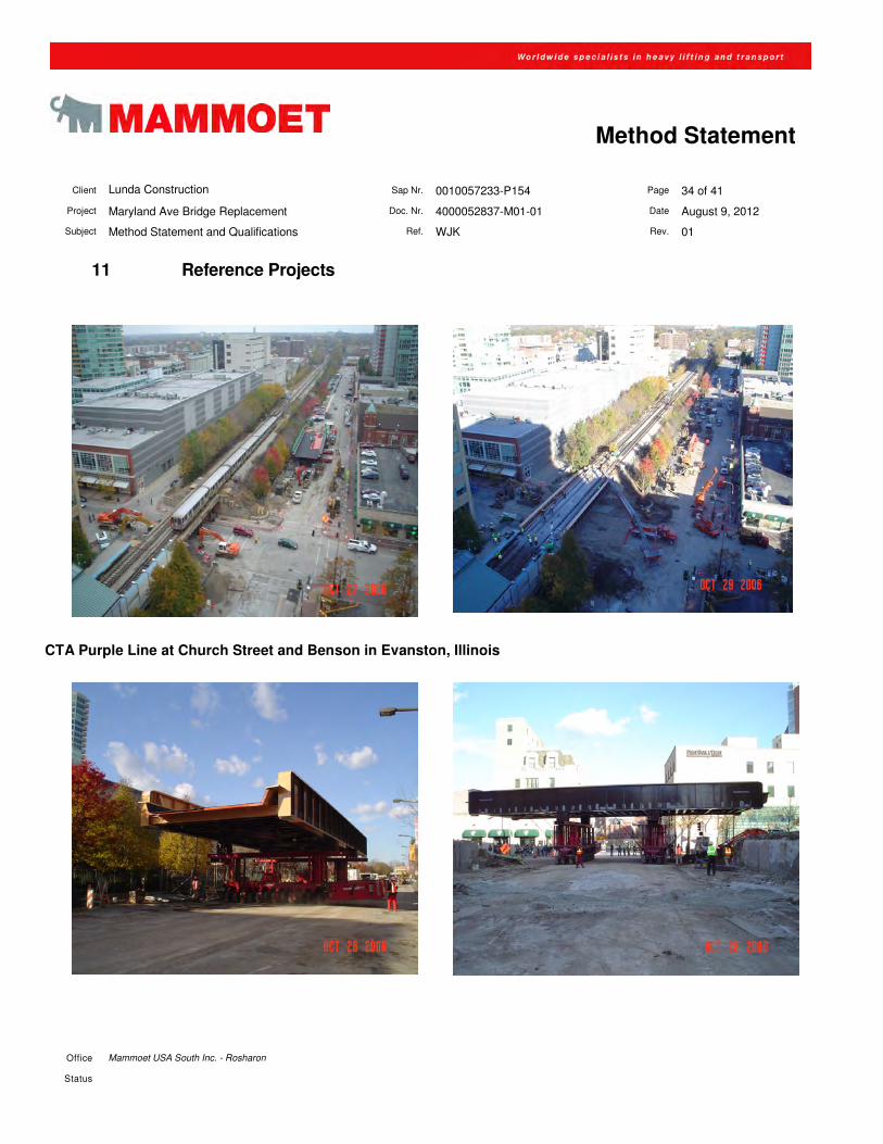
11 Reference Projects
CTA Purple Line at Church Street and Benson in Evanston, Illinois
Client Lunda Construction Sap Nr. 0010057233-P154 Page 35 of 41
Project Maryland Ave Bridge Replacement Doc. Nr. 4000052837-M01-01 Date August 9, 2012
Subject Method Statement and Qualifications Ref. WJK Rev. 01
Office Mammoet USA South Inc. - Rosharon
Status
Method Statement
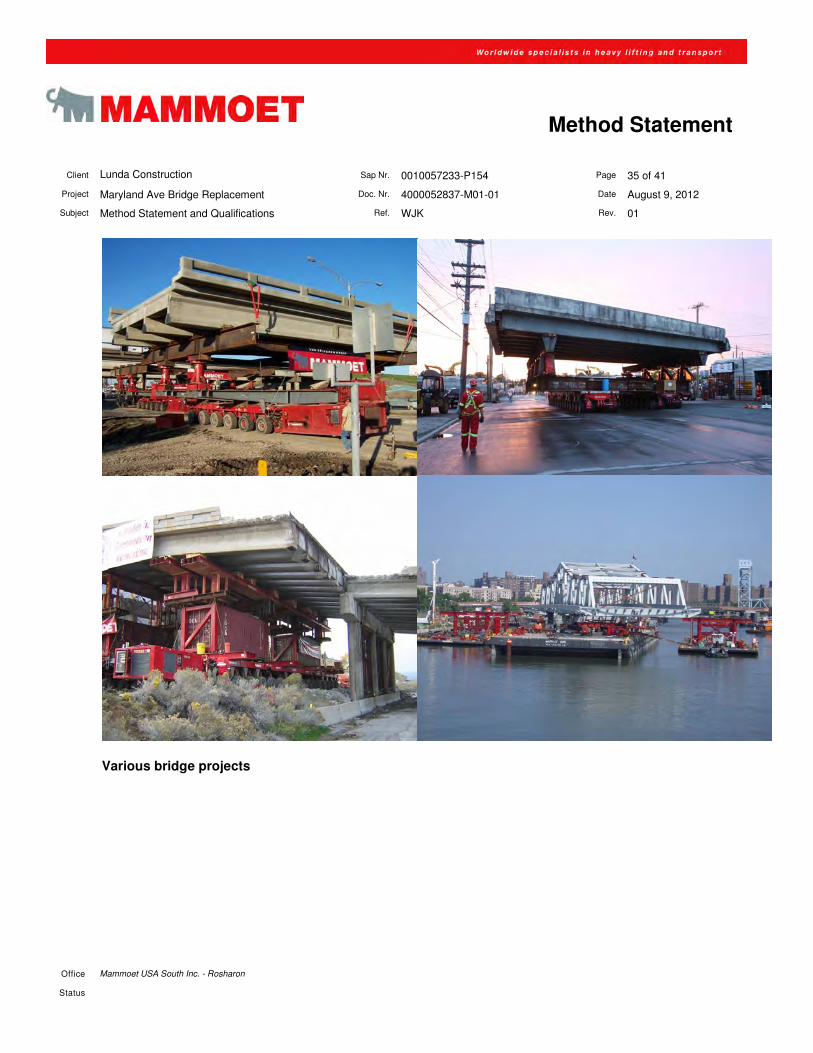
Various bridge projects
Client Lunda Construction Sap Nr. 0010057233-P154 Page 36 of 41
Project Maryland Ave Bridge Replacement Doc. Nr. 4000052837-M01-01 Date August 9, 2012
Subject Method Statement and Qualifications Ref. WJK Rev. 01
Office Mammoet USA South Inc. - Rosharon
Status
Method Statement
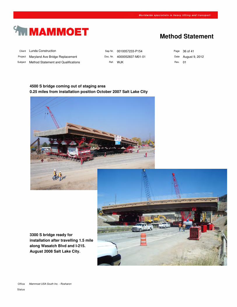
4500 S bridge coming out of staging area
0.25 miles from installation position October 2007 Salt Lake City
3300 S bridge ready for
installation after travelling 1.5 mile
along Wasatch Blvd and I-215.
August 2008 Salt Lake City.
Client Lunda Construction Sap Nr. 0010057233-P154 Page 37 of 41
Project Maryland Ave Bridge Replacement Doc. Nr. 4000052837-M01-01 Date August 9, 2012
Subject Method Statement and Qualifications Ref. WJK Rev. 01
Office Mammoet USA South Inc. - Rosharon
Status
Method Statement
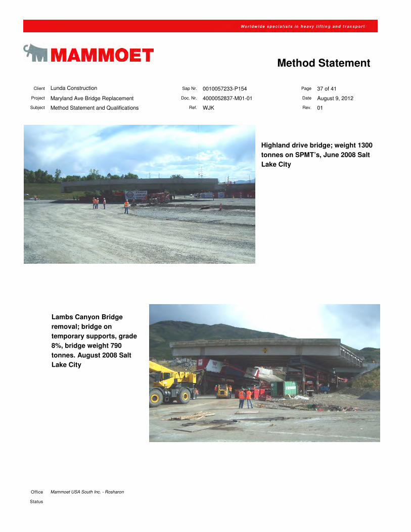
Highland drive bridge; weight 1300
tonnes on SPMT’s, June 2008 Salt
Lake City
Lambs Canyon Bridge
removal; bridge on
temporary supports, grade
8%, bridge weight 790
tonnes. August 2008 Salt
Lake City
Client Lunda Construction Sap Nr. 0010057233-P154 Page 38 of 41
Project Maryland Ave Bridge Replacement Doc. Nr. 4000052837-M01-01 Date August 9, 2012
Subject Method Statement and Qualifications Ref. WJK Rev. 01
Office Mammoet USA South Inc. - Rosharon
Status
Method Statement
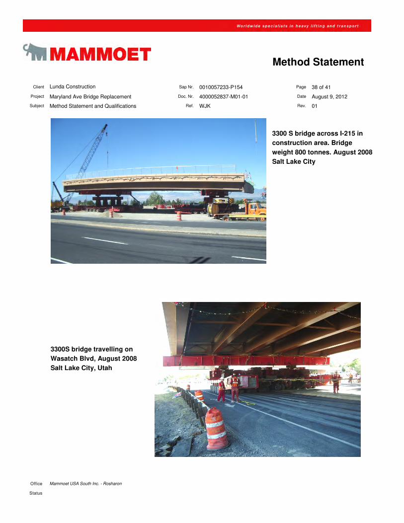
3300 S bridge across I-215 in
construction area. Bridge
weight 800 tonnes. August 2008
Salt Lake City
3300S bridge travelling on
Wasatch Blvd, August 2008
Salt Lake City, Utah
Client Lunda Construction Sap Nr. 0010057233-P154 Page 39 of 41
Project Maryland Ave Bridge Replacement Doc. Nr. 4000052837-M01-01 Date August 9, 2012
Subject Method Statement and Qualifications Ref. WJK Rev. 01
Office Mammoet USA South Inc. - Rosharon
Status
Method Statement
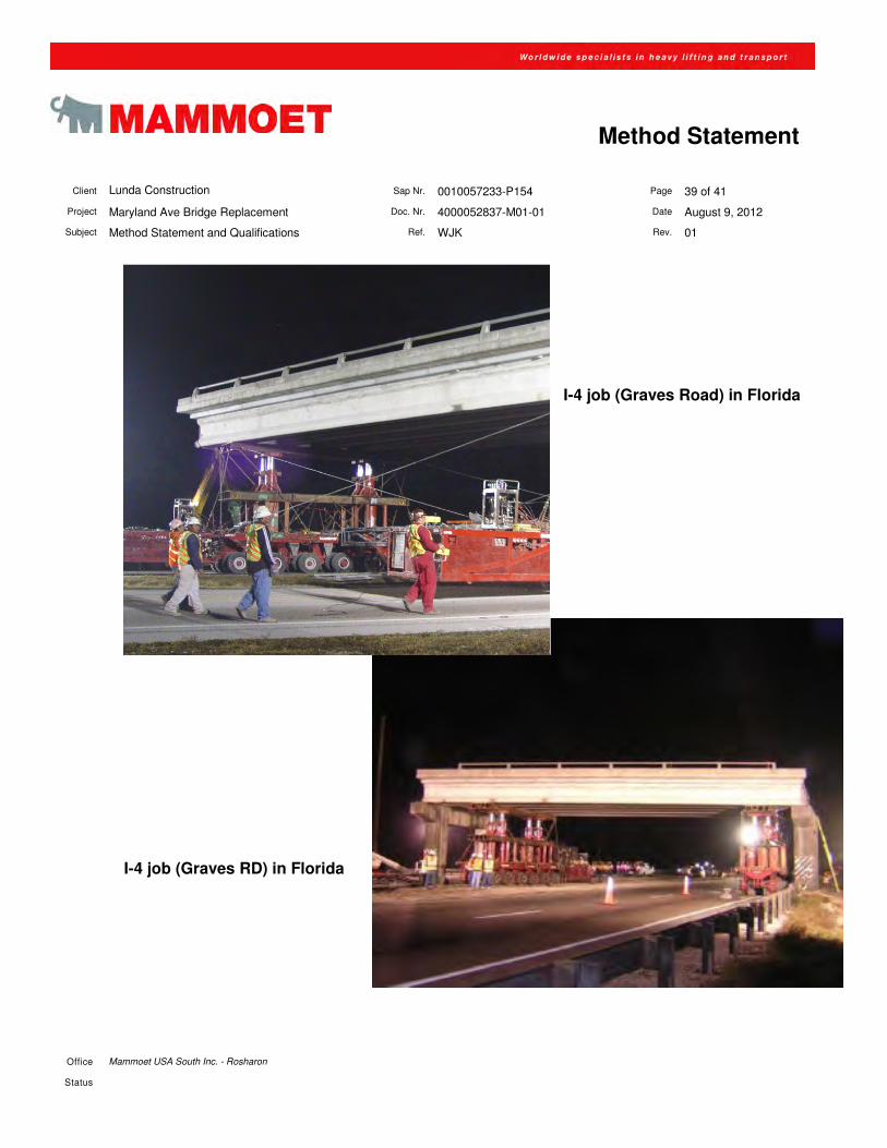
I-4 job (Graves Road) in Florida
I-4 job (Graves RD) in Florida
Client Lunda Construction Sap Nr. 0010057233-P154 Page 40 of 41
Project Maryland Ave Bridge Replacement Doc. Nr. 4000052837-M01-01 Date August 9, 2012
Subject Method Statement and Qualifications Ref. WJK Rev. 01
Office Mammoet USA South Inc. - Rosharon
Status
Method Statement
Client Lunda Construction Sap Nr. 0010057233-P154 Page 41 of 41
Project Maryland Ave Bridge Replacement Doc. Nr. 4000052837-M01-01 Date August 9, 2012
Subject Method Statement and Qualifications Ref. WJK Rev. 01
Office Mammoet USA South Inc. - Rosharon
Status
Method Statement
12 Appendix – Personnel Resumes
12.1 Dennis Theis
12.2 Craig White
12.3 Alfred Cox
12.4 Eddie Arroyo
Resume Name : Dennis Theis Address : 40 North Erik, Angleton, Texas 77515 Date of Birth : January 23, 1971 Date of employment : February 17, 1992 Present position : Transport Supervisor Education Training Specialized training from the manufacturer regarding the production and operation of Mammoet’s proprietary product line of equipment Work Experience Supervises heavy transport activities using self-propelled modular transporters (SPMT) since 1992
• Bechtel-Jacobs CEP Port Arthur JV - Port Arthur TX Motiva Crude Expansion
• SGT - St. Lucie FL Steam Generator &Reactor Replacement Project Unit 2
• Jacobs Engineering – Port Arthur TX Motiva PAR HTU5 Project Transport/Lift
• Cardi Corp - Providence River Bridge Remove Replace • Bechtel Power Corp – Rockdale TX Bechtel Steam Generator HP/IP
Install • Marinette Marine – Marinette WI Oversized Transportation 3 Ferries • Kiewit Construction - Manhattan NY Bridge Lift • AVS Services - Joliet Billings 4 Reactors Lift/Transport • Signal International LLC - Orange, TX Stack Tension Leg Platform
Loud Out • Fluor – Sweeny TX Clean Fuels Project • Fluor – Norco LA Hydrocracker Complete Load Out Transport • Gulf Island – Houma LA Alma Jacket and Topside Load Out • Pride International – Lake Charles LA Mad Dog DSM • Lexicon – Trinidad Steel Mill Unload • J Ray McDermott – Holstein Various Modules Load Out • Invista – Charlotte NC (2) Oxidizers Relocate
• BP – Whiting IN BP Canadian Crude Lift and Transport
Present Employment Mammoet USA South, Inc., Rosharon, Texas
Transport Supervisor
1 | P a g e
SPMT BRIDGE MOVE
MONITORING PLAN
Minnesota Department of Transportation
Metro District
Maryland Avenue Bridge Design‐Build Project
August 10, 2012
SPMT Monitoring Plan
1. Key Contacts for decisions during the move.
i. Mammoet – Dennis Thies – SPMT supervisor. Dennis will
be responsible for decisions directly related to the
Operations of SPMT equipment.
ii. Parsons – Steve Haines – SPMT Engineer. Steve will be
responsible for reviewing equipment and travel paths prior
to the lift and moves. Steve will coordinate his review with
Dennis. Steve will also directly supervise twist monitoring
during the move.
iii. Lunda Construction – Dale Even – Project Manager. Dale
will be responsible for overall project coordination during
the lift and moves.
2 | P a g e
iv. Any technical issues during the move will be resolved as
needed between Dennis, Steve, and Dale. The first line of
communication is between Dennis and Steve.
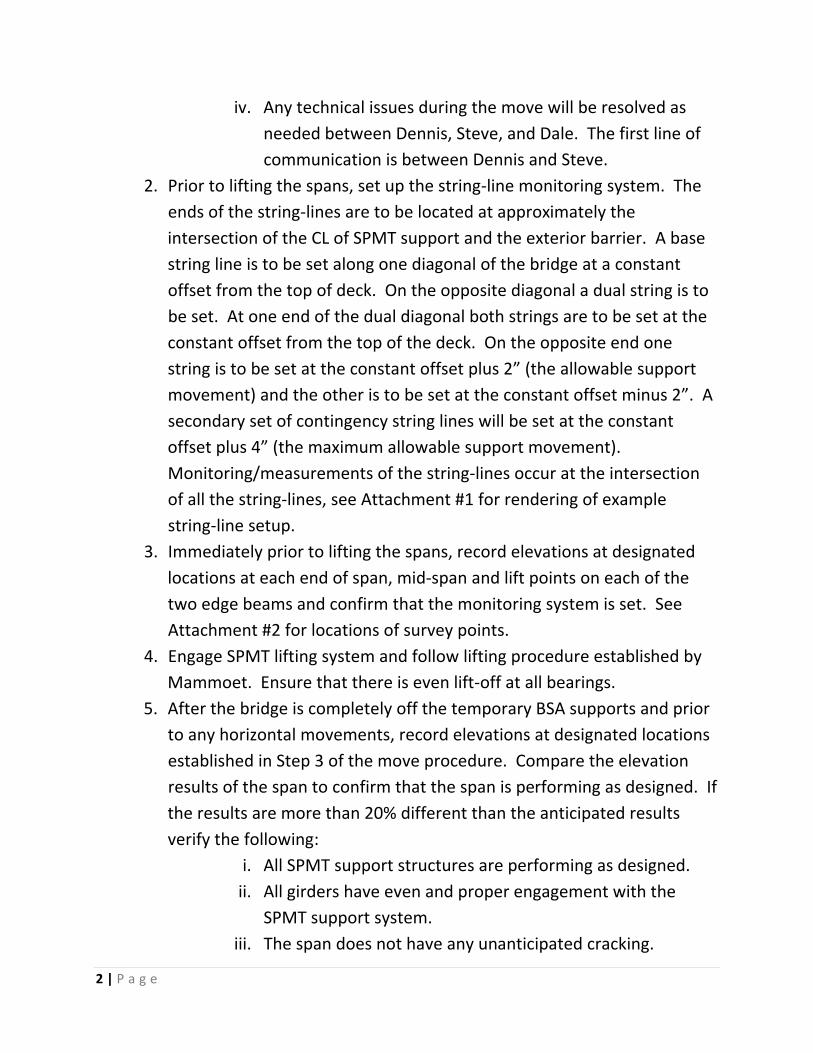
2. Prior to lifting the spans, set up the string‐line monitoring system. The
ends of the string‐lines are to be located at approximately the
intersection of the CL of SPMT support and the exterior barrier. A base
string line is to be set along one diagonal of the bridge at a constant
offset from the top of deck. On the opposite diagonal a dual string is to
be set. At one end of the dual diagonal both strings are to be set at the
constant offset from the top of the deck. On the opposite end one
string is to be set at the constant offset plus 2” (the allowable support
movement) and the other is to be set at the constant offset minus 2”. A
secondary set of contingency string lines will be set at the constant
offset plus 4” (the maximum allowable support movement).
Monitoring/measurements of the string‐lines occur at the intersection
of all the string‐lines, see Attachment #1 for rendering of example
string‐line setup.
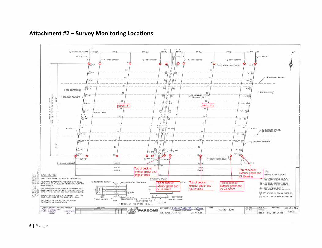
3. Immediately prior to lifting the spans, record elevations at designated
locations at each end of span, mid‐span and lift points on each of the
two edge beams and confirm that the monitoring system is set. See
Attachment #2 for locations of survey points.
4. Engage SPMT lifting system and follow lifting procedure established by
Mammoet. Ensure that there is even lift‐off at all bearings.
5. After the bridge is completely off the temporary BSA supports and prior
to any horizontal movements, record elevations at designated locations
established in Step 3 of the move procedure. Compare the elevation
results of the span to confirm that the span is performing as designed. If
the results are more than 20% different than the anticipated results
verify the following:
i. All SPMT support structures are performing as designed.
ii. All girders have even and proper engagement with the
SPMT support system.
iii. The span does not have any unanticipated cracking.
3 | P a g e
Discuss technical resolution among Key Contacts prior to proceeding.
6. When the span has been successfully lifted and any issues have been
addressed, proceed with transporting the new bridge to the final bridge
location.
7. During the transporting of the new bridge, Steve will actively monitor
the string‐lines along with a Lunda Construction representative. Steve
will communicate with Dale any adjustments required to keep the span
within the twist tolerance. Dale will communicate required adjustments
to Dennis who will implement the adjustment. Typically, adjustments
will be made prior to being close to the twist limit which will allow the
span to keep moving while the adjustments are being made. If the twist
limit is reached, Steve will issue an immediate stop request and the span
movement will be stopped by Dale and Dennis. Adjustments will be
made to re‐center the string‐lines. Once all adjustments are made then
the span movement can resume. The 2” limit line will be shifted by
hand for the first 10 occurrences that exceed the limit. If 10 or more
occurrences occur then we will clip the 2” limit lines and utilize the 4”
limit lines to give us more twist tolerance while staying within the
allowable limit.
8. As the span gets close to the approximate final bridge location all
clearances are to be checked visually to ensure the span does not have
any conflicts with the intended final location. Vertical, horizontal and
skew clearances are to be checked. Visual verification will be performed
by all available personnel in the vicinity. Dale will be notified of any
potential conflicts and determine if the movement needs to be stopped.
If the movement is stopped, it will not be resumed until the conflict is
resolved by Dale.
9. Bring span into close proximity in elevation and location. Check that all
permanent supports are at planned elevations and match the underside
elevations, slope and profile of the new bridge. The Key Contacts will
evaluate if any shimming or grinding is required. Dale will execute any
shim installation or grinding required to provide even support to all the
girders prior to the span being set.

4 | P a g e
10. Once elevation differences are resolve, set span down on bearings. 11. Take final set of elevation observations after setting the new bridge in
the final place to verify the permanent in place elevations.
5 | P a g e
Attachment #1 – String‐line Setup Rendering
6 | P a g e
Attachment #2 – Survey Monitoring Locations


![CASE STUDY - PSC 8.5x11[3].pdfpacks) and one knuckle boom crane to complete rigging and handling during the refueling outage. SPMT: PSC’s SPMT skillfully maneuvered the crowed worksite](https://img.pdfslide.us/doc/110x75/61173e1cd665b624766e0bfc/case-study-85x113pdf-packs-and-one-knuckle-boom-crane-to-complete-rigging.jpg)