Embed Size (px)
Citation preview
SPM15 SeriesSingle Output Potted Metal PackageIsolated 15-Watt DC-DC Converters
MDC_SPM15.C04 Page 1 of 36
www.murata-ps.com
www.murata-ps.com/support
For full details go towww.murata-ps.com/rohs
Typical unit
PRODUCT OVERVIEW
The SPM15 series isolated DC-DC converters represent the next generation in Industrial Potted Module Technology. Featuring a full 15-Watt output in one square inch of board area, the SPM15 series isolated DC-DC converter family offers effi cient regulated DC power for printed circuit board mounting. The 1˝ x 1˝ x 0.41˝ (25.4 x 25.4 x 10.41 mm) converter accepts a wide range of input volt-ages, ideal for industrial applications.
Intended target markets include transportation, medical systems, electronic test equipment, indus-trial processing equipment, industrial applications where power modules must meet rugged envi-ronmental requirements, high power density, and where isolated output voltages are required. These
converters offer a feature/option set including: through-hole mounting, positive or negative logic (remote on/off), over-current & over-temperature protection, under-voltage lockout. The input voltage range covers the standard Industrial requirements with a regulated output voltage and power rating up to 15W.
Modules provide voltage isolation (basic insulation) from input to output of up to 1600V. The Operating Ambient Temperature Range is -40°C to +85°C.The Module delivers full output power to +70°C with no airfl ow. These parts are ideal for applications that do not require any heat sinking or forced air cooling.
FEATURES
Wide range input voltages 9-36 and 18-75 Vdc
1˝ x 1˝ x 0.41˝ Dimensions.
Adjustable Vout (+10% to -10%)
High Effi ciency
Positive & Negative logic, Remote On/Off control Option
Monotonic startup
Continuous Short Circuit protection
Over-temperature protection
Over-Voltage protection
Low output ripple and noise
Strong thermal derating characteristics
Operational Temperature Range –40°C to +85°C
1600V I/O isolation
Packaged in a fi ve-sided EMI shielding metal package with non-conductive base
Certifi ed to UL 60950-1, CAN/CSA-C22.2 No. 60950-1, IEC60950-1, safety approvals, 2nd edition, with AM1
SPM15 SeriesSingle Output Potted Metal Package Isolated 15-Watt DC-DC Converters
MDC_SPM15.C04 Page 2 of 36
www.murata-ps.com/support
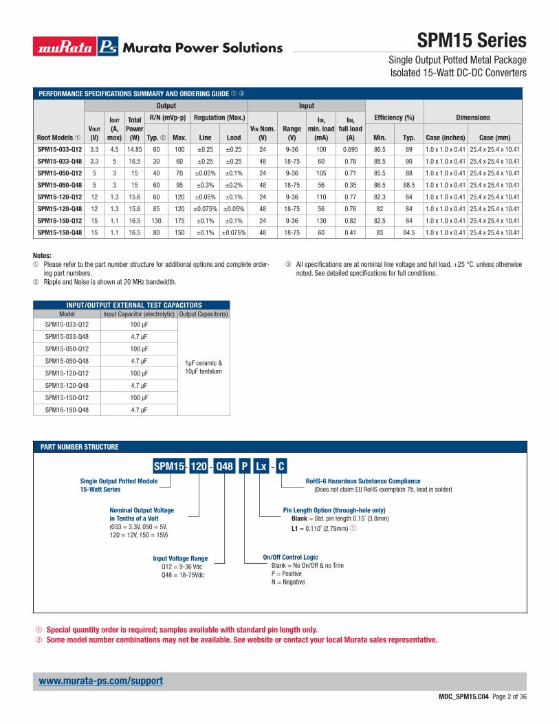
PART NUMBER STRUCTURE
PERFORMANCE SPECIFICATIONS SUMMARY AND ORDERING GUIDE ➀ ➂
Root Models ➀
Output Input
Effi ciency (%) Dimensions
VOUT
(V)
IOUT
(A,
max)
Total
Power
(W)
R/N (mVp-p) Regulation (Max.)
VIN Nom.
(V)
Range
(V)
IIN,
min. load
(mA)
IIN,
full load
(A)Typ. ➁ Max. Line Load Min. Typ. Case (inches) Case (mm)
SPM15-033-Q12 3.3 4.5 14.85 60 100 ±0.25 ±0.25 24 9-36 100 0.695 86.5 89 1.0 x 1.0 x 0.41 25.4 x 25.4 x 10.41
SPM15-033-Q48 3.3 5 16.5 30 60 ±0.25 ±0.25 48 18-75 60 0.76 88.5 90 1.0 x 1.0 x 0.41 25.4 x 25.4 x 10.41
SPM15-050-Q12 5 3 15 40 70 ±0.05% ±0.1% 24 9-36 105 0.71 85.5 88 1.0 x 1.0 x 0.41 25.4 x 25.4 x 10.41
SPM15-050-Q48 5 3 15 60 95 ±0.3% ±0.2% 48 18-75 56 0.35 86.5 88.5 1.0 x 1.0 x 0.41 25.4 x 25.4 x 10.41
SPM15-120-Q12 12 1.3 15.6 60 120 ±0.05% ±0.1% 24 9-36 110 0.77 82.3 84 1.0 x 1.0 x 0.41 25.4 x 25.4 x 10.41
SPM15-120-Q48 12 1.3 15.6 85 120 ±0.075% ±0.05% 48 18-75 56 0.76 82 84 1.0 x 1.0 x 0.41 25.4 x 25.4 x 10.41
SPM15-150-Q12 15 1.1 16.5 130 175 ±0.1% ±0.1% 24 9-36 130 0.82 82.5 84 1.0 x 1.0 x 0.41 25.4 x 25.4 x 10.41
SPM15-150-Q48 15 1.1 16.5 80 150 ±0.1% ±0.075% 48 18-75 60 0.41 83 84.5 1.0 x 1.0 x 0.41 25.4 x 25.4 x 10.41
Nominal Output Voltage
in Tenths of a Volt
(033 = 3.3V, 050 = 5V, 120 = 12V, 150 = 15V)
Single Output Potted Module
15-Watt Series
SPM15- Q48-120 - C
RoHS-6 Hazardous Substance Compliance
(Does not claim EU RoHS exemption 7b, lead in solder)
Input Voltage Range
Q12 = 9-36 Vdc Q48 = 18-75Vdc
P
On/Off Control Logic
Blank = No On/Off & no Trim P = Positive N = Negative
Notes:
➀ Please refer to the part number structure for additional options and complete order-ing part numbers.
➁ Ripple and Noise is shown at 20 MHz bandwidth.
➂ All specifi cations are at nominal line voltage and full load, +25 °C. unless otherwise noted. See detailed specifi cations for full conditions.
Lx
Pin Length Option (through-hole only)
Blank = Std. pin length 0.15˝ (3.8mm)
L1 = 0.110˝ (2.79mm) ➀
➀ Special quantity order is required; samples available with standard pin length only.
➁ Some model number combinations may not be available. See website or contact your local Murata sales representative.
INPUT/OUTPUT EXTERNAL TEST CAPACITORS
Model Input Capacitor (electrolytic) Output Capacitor(s)
SPM15-033-Q12 100 μF
1μF ceramic & 10μF tantalum
SPM15-033-Q48 4.7 μF
SPM15-050-Q12 100 μF
SPM15-050-Q48 4.7 μF
SPM15-120-Q12 100 μF
SPM15-120-Q48 4.7 μF
SPM15-150-Q12 100 μF
SPM15-150-Q48 4.7 μF
SPM15 SeriesSingle Output Potted Metal Package Isolated 15-Watt DC-DC Converters
MDC_SPM15.C04 Page 3 of 36
www.murata-ps.com/support
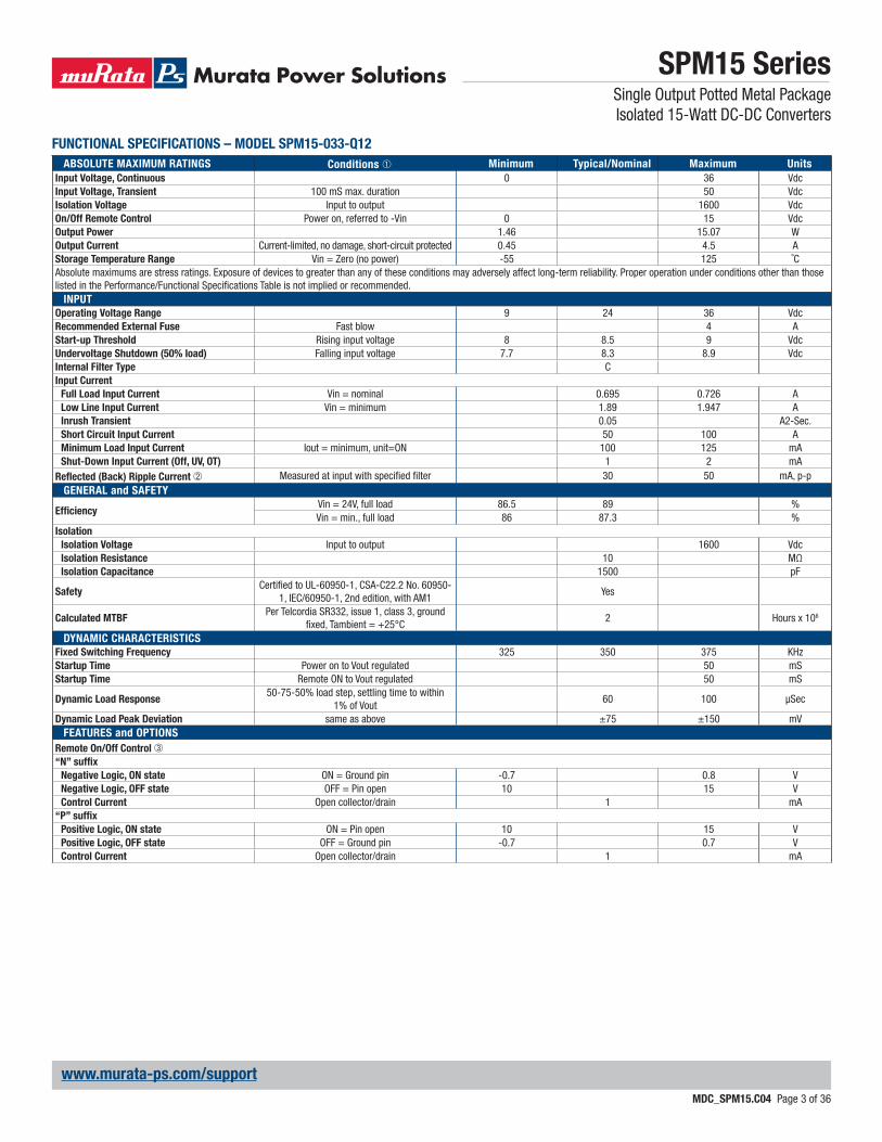
FUNCTIONAL SPECIFICATIONS – MODEL SPM15-033-Q12
ABSOLUTE MAXIMUM RATINGS Conditions ➀ Minimum Typical/Nominal Maximum Units
Input Voltage, Continuous 0 36 VdcInput Voltage, Transient 100 mS max. duration 50 VdcIsolation Voltage Input to output 1600 VdcOn/Off Remote Control Power on, referred to -Vin 0 15 VdcOutput Power 1.46 15.07 WOutput Current Current-limited, no damage, short-circuit protected 0.45 4.5 AStorage Temperature Range Vin = Zero (no power) -55 125 ˚CAbsolute maximums are stress ratings. Exposure of devices to greater than any of these conditions may adversely affect long-term reliability. Proper operation under conditions other than those listed in the Performance/Functional Specifi cations Table is not implied or recommended.
INPUT
Operating Voltage Range 9 24 36 VdcRecommended External Fuse Fast blow 4 AStart-up Threshold Rising input voltage 8 8.5 9 VdcUndervoltage Shutdown (50% load) Falling input voltage 7.7 8.3 8.9 VdcInternal Filter Type CInput Current
Full Load Input Current Vin = nominal 0.695 0.726 ALow Line Input Current Vin = minimum 1.89 1.947 AInrush Transient 0.05 A2-Sec.Short Circuit Input Current 50 100 AMinimum Load Input Current Iout = minimum, unit=ON 100 125 mAShut-Down Input Current (Off, UV, OT) 1 2 mA
Refl ected (Back) Ripple Current ➁ Measured at input with specifi ed fi lter 30 50 mA, p-pGENERAL and SAFETY
Effi ciencyVin = 24V, full load 86.5 89 %Vin = min., full load 86 87.3 %
Isolation
Isolation Voltage Input to output 1600 VdcIsolation Resistance 10 MΩIsolation Capacitance 1500 pF
SafetyCertifi ed to UL-60950-1, CSA-C22.2 No. 60950-
1, IEC/60950-1, 2nd edition, with AM1Yes
Calculated MTBFPer Telcordia SR332, issue 1, class 3, ground
fi xed, Tambient = +25°C2 Hours x 106
DYNAMIC CHARACTERISTICS
Fixed Switching Frequency 325 350 375 KHzStartup Time Power on to Vout regulated 50 mSStartup Time Remote ON to Vout regulated 50 mS
Dynamic Load Response50-75-50% load step, settling time to within
1% of Vout60 100 μSec
Dynamic Load Peak Deviation same as above ±75 ±150 mVFEATURES and OPTIONS
Remote On/Off Control ➂“N” suffi x
Negative Logic, ON state ON = Ground pin -0.7 0.8 VNegative Logic, OFF state OFF = Pin open 10 15 VControl Current Open collector/drain 1 mA
“P” suffi x
Positive Logic, ON state ON = Pin open 10 15 VPositive Logic, OFF state OFF = Ground pin -0.7 0.7 VControl Current Open collector/drain 1 mA
SPM15 SeriesSingle Output Potted Metal Package Isolated 15-Watt DC-DC Converters
MDC_SPM15.C04 Page 4 of 36
www.murata-ps.com/support
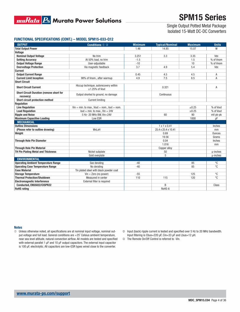
OUTPUT Conditions ➀ ➂ Minimum Typical/Nominal Maximum Units
Total Output Power 1.46 14.85 15.07 WVoltage
Nominal Output Voltage No trim 3.251 3.3 3.35 VdcSetting Accuracy At 50% load, no trim -1.5 1.5 % of VnomOutput Voltage Range User-adjustable -10 10 % of VnomOvervoltage Protection Via magnetic feedback 3.7 4.9 5.4 Vdc
Current
Output Current Range 0.45 4.5 4.5 ACurrent Limit Inception 98% of Vnom., after warmup 4.9 7.5 8.5 A
Short Circuit
Short Circuit CurrentHiccup technique, autorecovery within
±1.25% of Vout0.321 A
Short Circuit Duration (remove short for
recovery)Output shorted to ground, no damage Continuous
Short circuit protection method Current limitingRegulation
Line Regulation Vin = min. to max., Vout = nom., Iout = nom. ±0.25 % of VoutLoad Regulation Iout = min. to max., Vin = 24V ±0.25 % of Vout
Ripple and Noise 5 Hz- 20 MHz BW, Vin=24V 60 90 mV pk-pkMaximum Capacitive Loading Low ESR 1000 μF
MECHANICAL
Outline Dimensions 1 x 1 x 0.41 Inches(Please refer to outline drawing) WxLxH 25.4 x 25.4 x 10.41 mm
Weight 0.69 Ounces19.56 Grams
Through Hole Pin Diameter 0.04 Inches1.016 mm
Through Hole Pin Material Copper alloyTH Pin Plating Metal and Thickness Nickel subplate 50 μ-inches
Gold overplate 5 μ-inchesENVIRONMENTAL
Operating Ambient Temperature Range See derating -40 85 °COperating Case Temperature Range No derating -40 85 °CCase Material Tin plated steel with black powder coatStorage Temperature Vin = Zero (no power) -55 125 °CThermal Protection/Shutdown Measured in center 110 115 120 °CElectromagnetic Interference External fi lter is required
Conducted, EN55022/CISPR22 B ClassRoHS rating RoHS-6
FUNCTIONAL SPECIFICATIONS (CONT.) – MODEL SPM15-033-Q12
Notes➀ Unless otherwise noted, all specifi cations are at nominal input voltage, nominal out-
put voltage and full load. General conditions are +25˚ Celsius ambient temperature, near sea level altitude, natural convection airfl ow. All models are tested and specifi ed with external parallel 1 μF and 10 μF output capacitors. The external input capacitor is 100 μF, electrolytic. All capacitors are low-ESR types wired close to the converter.
➁ Input (back) ripple current is tested and specifi ed over 5 Hz to 20 MHz bandwidth. Input fi ltering is Cbus=220 μF, Cin=33 μF and Lbus=12 μH.
➂ The Remote On/Off Control is referred to -Vin.
SPM15 SeriesSingle Output Potted Metal Package Isolated 15-Watt DC-DC Converters
MDC_SPM15.C04 Page 5 of 36
www.murata-ps.com/support
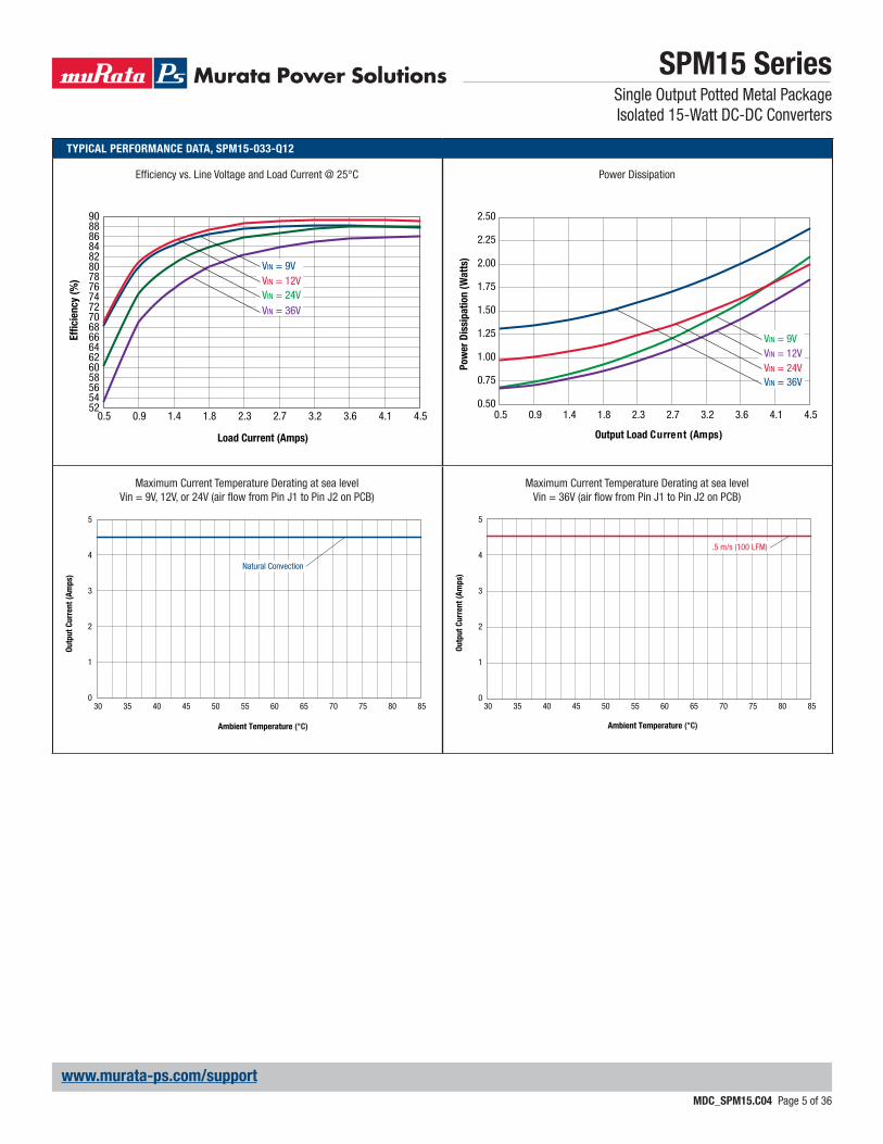
TYPICAL PERFORMANCE DATA, SPM15-033-Q12
9088868482807876747270686664626058565452
0.5 0.9 1.4 1.8 2.3 2.7 3.2 3.6 4.1 4.5
Effi
cie
ncy (
%)
Load Current (Amps)
VIN = 9VVIN = 12VVIN = 24VVIN = 36V
Maximum Current Temperature Derating at sea levelVin = 9V, 12V, or 24V (air fl ow from Pin J1 to Pin J2 on PCB)
Maximum Current Temperature Derating at sea levelVin = 36V (air fl ow from Pin J1 to Pin J2 on PCB)
0
1
2
3
4
5
30 35 40 45 50 55 60 65 70 75 80 85
Ou
tpu
t C
urr
en
t (A
mp
s)
Ambient Temperature (°C)
Natural Convection
0
1
2
3
4
5
30 35 40 45 50 55 60 65 70 75 80 85
Ou
tpu
t C
urr
en
t (A
mp
s)
Ambient Temperature (°C)
.5 m/s (100 LFM)
Effi ciency vs. Line Voltage and Load Current @ 25°C Power Dissipation
0.50
0.75
1.00
1.25
1.50
1.75
2.00
2.25
2.50
0.5 0.9 1.4 1.8 2.3 2.7 3.2 3.6 4.1 4.5
VIN = 9VVIN = 12VVIN = 24VVIN = 36V
Output Load Current (Amps)
Pow
er
Dis
sip
ati
on
(W
att
s)
SPM15 SeriesSingle Output Potted Metal Package Isolated 15-Watt DC-DC Converters
MDC_SPM15.C04 Page 6 of 36
www.murata-ps.com/support
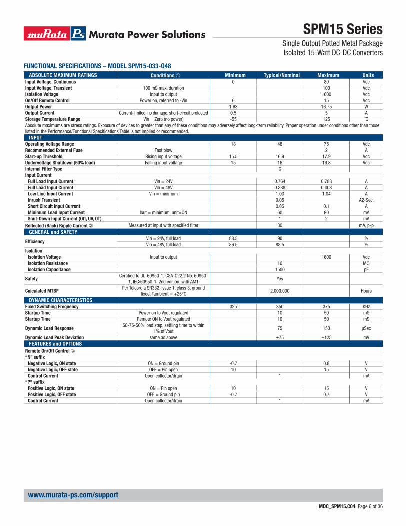
FUNCTIONAL SPECIFICATIONS – MODEL SPM15-033-Q48
ABSOLUTE MAXIMUM RATINGS Conditions ➀ Minimum Typical/Nominal Maximum Units
Input Voltage, Continuous 0 80 VdcInput Voltage, Transient 100 mS max. duration 100 VdcIsolation Voltage Input to output 1600 VdcOn/Off Remote Control Power on, referred to -Vin 0 15 VdcOutput Power 1.63 16.75 WOutput Current Current-limited, no damage, short-circuit protected 0.5 5 AStorage Temperature Range Vin = Zero (no power) -55 125 ˚CAbsolute maximums are stress ratings. Exposure of devices to greater than any of these conditions may adversely affect long-term reliability. Proper operation under conditions other than those listed in the Performance/Functional Specifi cations Table is not implied or recommended.
INPUT
Operating Voltage Range 18 48 75 VdcRecommended External Fuse Fast blow 2 AStart-up Threshold Rising input voltage 15.5 16.9 17.9 VdcUndervoltage Shutdown (50% load) Falling input voltage 15 16 16.8 VdcInternal Filter Type CInput Current
Full Load Input Current Vin = 24V 0.764 0.788 AFull Load Input Current Vin = 48V 0.388 0.403 ALow Line Input Current Vin = minimum 1.03 1.04 AInrush Transient 0.05 A2-Sec.Short Circuit Input Current 0.05 0.1 AMinimum Load Input Current Iout = minimum, unit=ON 60 90 mAShut-Down Input Current (Off, UV, OT) 1 2 mA
Refl ected (Back) Ripple Current ➁ Measured at input with specifi ed fi lter 30 mA, p-pGENERAL and SAFETY
Effi ciencyVin = 24V, full load 88.5 90 %Vin = 48V, full load 86.5 88.5 %
Isolation
Isolation Voltage Input to output 1600 VdcIsolation Resistance 10 MΩIsolation Capacitance 1500 pF
SafetyCertifi ed to UL-60950-1, CSA-C22.2 No. 60950-
1, IEC/60950-1, 2nd edition, with AM1Yes
Calculated MTBFPer Telcordia SR332, issue 1, class 3, ground
fi xed, Tambient = +25°C2,000,000 Hours
DYNAMIC CHARACTERISTICS
Fixed Switching Frequency 325 350 375 KHzStartup Time Power on to Vout regulated 10 50 mSStartup Time Remote ON to Vout regulated 10 50 mS
Dynamic Load Response50-75-50% load step, settling time to within
1% of Vout75 150 μSec
Dynamic Load Peak Deviation same as above ±75 ±125 mVFEATURES and OPTIONS
Remote On/Off Control ➂“N” suffi x
Negative Logic, ON state ON = Ground pin -0.7 0.8 VNegative Logic, OFF state OFF = Pin open 10 15 VControl Current Open collector/drain 1 mA
“P” suffi x
Positive Logic, ON state ON = Pin open 10 15 VPositive Logic, OFF state OFF = Ground pin -0.7 0.7 VControl Current Open collector/drain 1 mA

SPM15 SeriesSingle Output Potted Metal Package Isolated 15-Watt DC-DC Converters
MDC_SPM15.C04 Page 7 of 36
www.murata-ps.com/support
OUTPUT Conditions ➀ ➂ Minimum Typical/Nominal Maximum Units
Total Output Power 1.63 16.5 16.75 WVoltage
Nominal Output Voltage No trim 3.2505 3.3 3.3495 VdcSetting Accuracy At 50% load, no trim 1.5 % of VnomOutput Voltage Range User-adjustable -10 10 % of VnomOvervoltage Protection Via magnetic feedback 4 5 5.6 Vdc
Current
Output Current Range 0.5 5 5 ACurrent Limit Inception 98% of Vnom., after warmup 5.9 7.3 8.4 A
Short Circuit
Short Circuit CurrentHiccup technique, autorecovery within
±1.25% of Vout0.3 A
Short Circuit Duration (remove short for
recovery)Output shorted to ground, no damage Continuous
Short circuit protection method Current limitingRegulation
Line Regulation Vin = min. to max., Vout = nom., Iout = nom. ±0.25 % of VoutLoad Regulation Iout = min. to max., Vin = 48V ±0.25 % of Vout
Ripple and Noise 20 MHz BW, Vin = 48V 30 60 mV pk-pkTemperature Coeffi cient At all outputs 0.02 % of Vnom./°CMaximum Capacitive Loading Low ESR 5000 μF
MECHANICAL
Outline Dimensions 1 x 1 x 0.41 Inches(Please refer to outline drawing) WxLxH 25.4 x 25.4 x 10.41 mm
Weight 0.69 Ounces19.56 Grams
Through Hole Pin Diameter 0.04 Inches1.016 mm
Through Hole Pin Material Copper alloyTH Pin Plating Metal and Thickness Nickel subplate 50 μ-inches
Gold overplate 5 μ-inchesENVIRONMENTAL
Operating Ambient Temperature Range See derating -40 85 °CCase Material Tin plated steel with black powder coatStorage Temperature Vin = Zero (no power) -55 125 °CThermal Protection/Shutdown Measured in center 120 130 140 °CElectromagnetic Interference External fi lter is required
Conducted, EN55022/CISPR22 B ClassRoHS rating RoHS-6
FUNCTIONAL SPECIFICATIONS (CONT.) – MODEL SPM15-033-Q48
Notes➀ Unless otherwise noted, all specifi cations are at nominal input voltage, nominal out-
put voltage and full load. General conditions are +25˚ Celsius ambient temperature, near sea level altitude, natural convection airfl ow. All models are tested and specifi ed with external parallel 1 μF and 10 μF output capacitors. The external input capacitor is 100 μF, electrolytic. All capacitors are low-ESR types wired close to the converter.
➁ Input (back) ripple current is tested and specifi ed over 5 Hz to 20 MHz bandwidth. Input fi ltering is Cbus=220 μF, Cin=33 μF and Lbus=12 μH.
➂ The Remote On/Off Control is referred to -Vin.
SPM15 SeriesSingle Output Potted Metal Package Isolated 15-Watt DC-DC Converters
MDC_SPM15.C04 Page 8 of 36
www.murata-ps.com/support
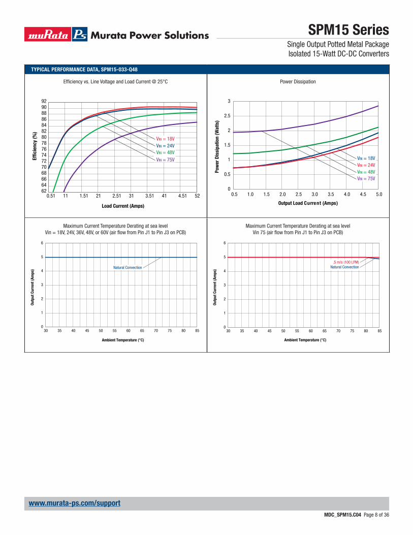
TYPICAL PERFORMANCE DATA, SPM15-033-Q48
62646668707274767880828486889092
0.51 11 1.51 21 2.51 31 3.51 41 4.51 52
Effi
cie
ncy (
%)
Load Current (Amps)
VIN = 18VVIN = 24VVIN = 48VVIN = 75V
Maximum Current Temperature Derating at sea levelVin = 18V, 24V, 36V, 48V, or 60V (air fl ow from Pin J1 to Pin J3 on PCB)
Maximum Current Temperature Derating at sea levelVin 75 (air fl ow from Pin J1 to Pin J3 on PCB)
0
1
2
3
4
5
6
30 35 40 45 50 55 60 65 70 75 80 85
Ou
tpu
t C
urr
en
t (A
mp
s)
Ambient Temperature (°C)
Natural Convection
0
1
2
3
4
5
6
30 35 40 45 50 55 60 65 70 75 80 85
Ou
tpu
t C
urr
en
t (A
mp
s)
Ambient Temperature (°C)
.5 m/s (100 LFM)Natural Convection
Effi ciency vs. Line Voltage and Load Current @ 25°C Power Dissipation
0
0.5
1
1.5
2
2.5
3
0.5 1.0 1.5 2.0 2.5 3.0 3.5 4.0 4.5 5.0
VIN = 18VVIN = 24VVIN = 48VVIN = 75V
Output Load Current (Amps)
Pow
er
Dis
sip
ati
on
(W
att
s)
SPM15 SeriesSingle Output Potted Metal Package Isolated 15-Watt DC-DC Converters
MDC_SPM15.C04 Page 9 of 36
www.murata-ps.com/support
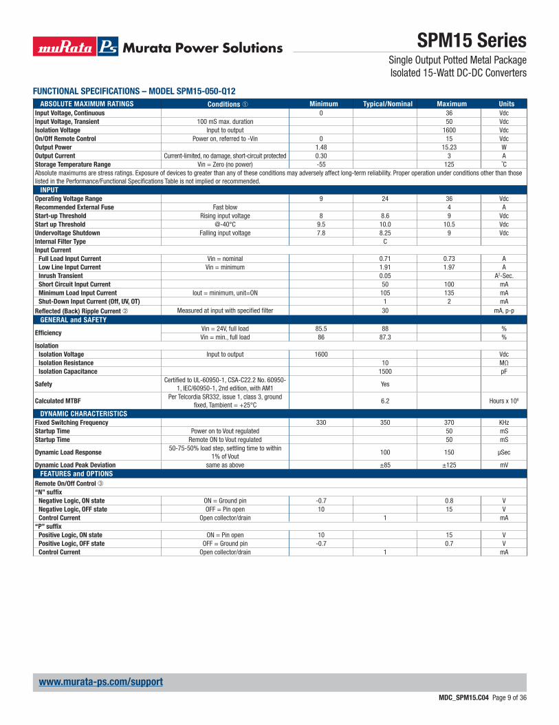
FUNCTIONAL SPECIFICATIONS – MODEL SPM15-050-Q12
ABSOLUTE MAXIMUM RATINGS Conditions ➀ Minimum Typical/Nominal Maximum Units
Input Voltage, Continuous 0 36 VdcInput Voltage, Transient 100 mS max. duration 50 VdcIsolation Voltage Input to output 1600 VdcOn/Off Remote Control Power on, referred to -Vin 0 15 VdcOutput Power 1.48 15.23 WOutput Current Current-limited, no damage, short-circuit protected 0.30 3 AStorage Temperature Range Vin = Zero (no power) -55 125 ˚CAbsolute maximums are stress ratings. Exposure of devices to greater than any of these conditions may adversely affect long-term reliability. Proper operation under conditions other than those listed in the Performance/Functional Specifi cations Table is not implied or recommended.
INPUT
Operating Voltage Range 9 24 36 VdcRecommended External Fuse Fast blow 4 AStart-up Threshold Rising input voltage 8 8.6 9 VdcStart up Threshold @-40°C 9.5 10.0 10.5 VdcUndervoltage Shutdown Falling input voltage 7.8 8.25 9 VdcInternal Filter Type CInput Current
Full Load Input Current Vin = nominal 0.71 0.73 ALow Line Input Current Vin = minimum 1.91 1.97 AInrush Transient 0.05 A2-Sec.Short Circuit Input Current 50 100 mAMinimum Load Input Current Iout = minimum, unit=ON 105 135 mAShut-Down Input Current (Off, UV, OT) 1 2 mA
Refl ected (Back) Ripple Current ➁ Measured at input with specifi ed fi lter 30 mA, p-pGENERAL and SAFETY
Effi ciencyVin = 24V, full load 85.5 88 %Vin = min., full load 86 87.3 %
Isolation
Isolation Voltage Input to output 1600 VdcIsolation Resistance 10 MΩIsolation Capacitance 1500 pF
SafetyCertifi ed to UL-60950-1, CSA-C22.2 No. 60950-
1, IEC/60950-1, 2nd edition, with AM1Yes
Calculated MTBFPer Telcordia SR332, issue 1, class 3, ground
fi xed, Tambient = +25°C6.2 Hours x 106
DYNAMIC CHARACTERISTICS
Fixed Switching Frequency 330 350 370 KHzStartup Time Power on to Vout regulated 50 mSStartup Time Remote ON to Vout regulated 50 mS
Dynamic Load Response50-75-50% load step, settling time to within
1% of Vout100 150 μSec
Dynamic Load Peak Deviation same as above ±85 ±125 mVFEATURES and OPTIONS
Remote On/Off Control ➂“N” suffi x
Negative Logic, ON state ON = Ground pin -0.7 0.8 VNegative Logic, OFF state OFF = Pin open 10 15 VControl Current Open collector/drain 1 mA
“P” suffi x
Positive Logic, ON state ON = Pin open 10 15 VPositive Logic, OFF state OFF = Ground pin -0.7 0.7 VControl Current Open collector/drain 1 mA

SPM15 SeriesSingle Output Potted Metal Package Isolated 15-Watt DC-DC Converters
MDC_SPM15.C04 Page 10 of 36
www.murata-ps.com/support
OUTPUT Conditions ➀ ➂ Minimum Typical/Nominal Maximum Units
Total Output Power 1.48 15 15.23 WVoltage
Nominal Output Voltage No trim 4.925 5 5.075 VdcSetting Accuracy At 50% load, no trim -1.5 1.5 % of VnomOutput Voltage Range User-adjustable -10 10 % of Vnom.Overvoltage Protection Via magnetic feedback 5.75 5.9 7 Vdc
Current
Output Current Range 0.3 3 3 ACurrent Limit Inception 98% of Vnom., after warmup 3.5 4.75 6.5 A
Short Circuit
Short Circuit CurrentHiccup technique, autorecovery within
±1.25% of Vout0.3 A
Short Circuit Duration (remove short for
recovery)Output shorted to ground, no damage Continuous
Short circuit protection method Current limitingRegulation
Line Regulation Vin = min. to max., Vout = nom., Iout = nom. ±0.05 % of VoutLoad Regulation Iout = min. to max., Vin = 24V ±0.1 % of Vout
Ripple and Noise 5 Hz- 20 MHz BW, Vin=24V 40 70 mV pk-pkTemperature Coeffi cient At all outputs ±0.02 % of Vnom./°CMaximum Capacitive Loading Low ESR 1000 μF
MECHANICAL
Outline Dimensions 1 x 1 x 0.41 Inches(Please refer to outline drawing) WxLxH 25.4 x 25.4 x 10.41 mm
Weight 0.69 Ounces19.56 Grams
Through Hole Pin Diameter 0.04 Inches1.016 mm
Through Hole Pin Material Copper alloyTH Pin Plating Metal and Thickness Nickel subplate 50 μ-inches
Gold overplate 5 μ-inchesENVIRONMENTAL
Operating Ambient Temperature Range See derating -40 85 °COperating Case Temperature Range No derating -40 105 °CCase Material Tin plated steel with black powder coatStorage Temperature Vin = Zero (no power) -55 125 °CThermal Protection/Shutdown Measured in center 110 115 120 °CElectromagnetic Interference External fi lter is required
Conducted, EN55022/CISPR22 B ClassRoHS rating RoHS-6
FUNCTIONAL SPECIFICATIONS (CONT.) – MODEL SPM15-050-Q12
Notes➀ Unless otherwise noted, all specifi cations are at nominal input voltage, nominal out-
put voltage and full load. General conditions are +25˚ Celsius ambient temperature, near sea level altitude, natural convection airfl ow. All models are tested and specifi ed with external parallel 1 μF and 10 μF output capacitors. The external input capacitor is 100 μF, electrolytic. All capacitors are low-ESR types wired close to the converter.
➁ Input (back) ripple current is tested and specifi ed over 5 Hz to 20 MHz bandwidth. Input fi ltering is Cbus=220 μF, Cin=33 μF and Lbus=12 μH.
➂ The Remote On/Off Control is referred to -Vin.
SPM15 SeriesSingle Output Potted Metal Package Isolated 15-Watt DC-DC Converters
MDC_SPM15.C04 Page 11 of 36
www.murata-ps.com/support
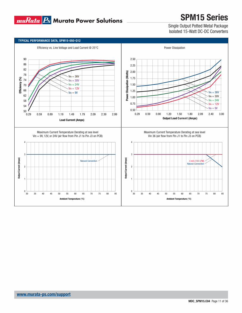
TYPICAL PERFORMANCE DATA, SPM15-050-Q12
50
54
58
62
66
70
74
78
82
86
90
0.29 0.59 0.89 1.19 1.49 1.79 2.09 2.39 2.99
Effi
cie
ncy (
%)
Load Current (Amps)
VIN = 36VVIN = 30VVIN = 24VVIN = 12VVIN = 9V
Maximum Current Temperature Derating at sea levelVin = 9V, 12V, or 24V (air fl ow from Pin J1 to Pin J3 on PCB)
Maximum Current Temperature Derating at sea levelVin 36 (air fl ow from Pin J1 to Pin J3 on PCB)
0
1
2
3
4
30 35 40 45 50 55 60 65 70 75 80 85
Ou
tpu
t C
urr
en
t (A
mp
s)
Ambient Temperature (°C)
Natural Convection
0
1
2
3
4
30 35 40 45 50 55 60 65 70 75 80 85
Ou
tpu
t C
urr
en
t (A
mp
s)
Ambient Temperature (°C)
.5 m/s (100 LFM)Natural Convection
Effi ciency vs. Line Voltage and Load Current @ 25°C Power Dissipation
0.50
0.75
1.00
1.25
1.50
1.75
2.00
2.25
2.50
0.29 0.59 0.90 1.20 1.50 1.80 2.09 2.40 3.00
VIN = 36VVIN = 30VVIN = 24VVIN = 12VVIN = 9V
Output Load Current (Amps)
Pow
er
Dis
sip
ati
on
(W
att
s)
SPM15 SeriesSingle Output Potted Metal PackageIsolated 15-Watt DC-DC Converters
MDC_SPM15.C04 Page 12 of 36
www.murata-ps.com/support
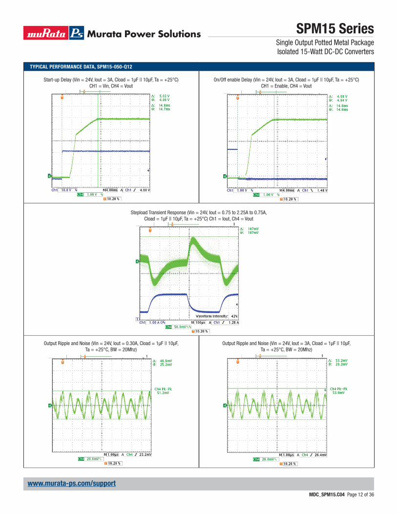
TYPICAL PERFORMANCE DATA, SPM15-050-Q12
Stepload Transient Response (Vin = 24V, Iout = 0.75 to 2.25A to 0.75A, Cload = 1μF || 10μF, Ta = +25°C) Ch1 = Iout, Ch4 = Vout
Start-up Delay (Vin = 24V, Iout = 3A, Cload = 1μF || 10μF, Ta = +25°C) CH1 = Vin, CH4 = Vout
Output Ripple and Noise (Vin = 24V, Iout = 0.30A, Cload = 1μF || 10μF, Ta = +25°C, BW = 20Mhz)
On/Off enable Delay (Vin = 24V, Iout = 3A, Cload = 1μF || 10μF, Ta = +25°C) CH1 = Enable, CH4 = Vout
Output Ripple and Noise (Vin = 24V, Iout = 3A, Cload = 1μF || 10μF, Ta = +25°C, BW = 20Mhz)

SPM15 SeriesSingle Output Potted Metal Package Isolated 15-Watt DC-DC Converters
MDC_SPM15.C04 Page 13 of 36
www.murata-ps.com/support
FUNCTIONAL SPECIFICATIONS – MODEL SPM15-050-Q48
ABSOLUTE MAXIMUM RATINGS Conditions ➀ Minimum Typical/Nominal Maximum Units
Input Voltage, Continuous 0 80 VdcInput Voltage, Transient 100 mS max. duration 100 VdcIsolation Voltage Input to output 1600 VdcOn/Off Remote Control Power on, referred to -Vin 0 15 VdcOutput Power 1.48 15.23 WOutput Current Current-limited, no damage, short-circuit protected 0.3 3 AStorage Temperature Range Vin = Zero (no power) -55 125 ˚CAbsolute maximums are stress ratings. Exposure of devices to greater than any of these conditions may adversely affect long-term reliability. Proper operation under conditions other than those listed in the Performance/Functional Specifi cations Table is not implied or recommended.
INPUT
Operating Voltage Range 18 48 75 VdcRecommended External Fuse Fast blow 1.5 AStart-up Threshold Rising input voltage 16 16.9 17.9 VdcUndervoltage Shutdown Falling input voltage 15 16 17.5 VdcInternal Filter Type CInput Current
Full Load Input Current Vin = nominal 0.35 0.37 ALow Line Input Current Vin = minimum 0.93 0.97 AInrush Transient 0.05 A2-Sec.Short Circuit Input Current 0.05 0.1 mAMinimum Load Input Current Iout = minimum, unit=ON 56 90 mAShut-Down Input Current (Off, UV, OT) 1 2 mA
Refl ected (Back) Ripple Current ➁ Measured at input with specifi ed fi lter 30 mA, p-pGENERAL and SAFETY
Effi ciencyVin = 48V, full load 86.5 88.5 %Vin = min., full load 87.5 89.5 %
Isolation
Isolation Voltage Input to output 1600 VdcIsolation Resistance 10 MΩIsolation Capacitance 1500 pF
SafetyCertifi ed to UL-60950-1, CSA-C22.2 No. 60950-
1, IEC/60950-1, 2nd edition, with AM1Yes
Calculated MTBFPer Telcordia SR332, issue 1, class 3, ground
fi xed, Tambient = +25°C2 Hours x 106
DYNAMIC CHARACTERISTICS
Fixed Switching Frequency 320 345 375 KHzStartup Time Power on to Vout regulated 10 50 mSStartup Time Remote ON to Vout regulated 10 100 mS
Dynamic Load Response50-75-50% load step, settling time to within
1% of Vout60 120 μSec
Dynamic Load Peak Deviation same as above ±50 ±150 mVFEATURES and OPTIONS
Remote On/Off Control ➂“N” suffi x
Negative Logic, ON state ON = Ground pin -0.7 0.8 VNegative Logic, OFF state OFF = Pin open 10 15 VControl Current Open collector/drain 1 mA
“P” suffi x
Positive Logic, ON state ON = Pin open 10 15 VPositive Logic, OFF state OFF = Ground pin -0.7 0.7 VControl Current Open collector/drain 1 mA
SPM15 SeriesSingle Output Potted Metal Package Isolated 15-Watt DC-DC Converters
MDC_SPM15.C04 Page 14 of 36
www.murata-ps.com/support
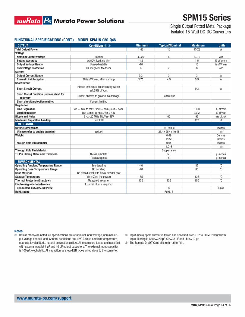
OUTPUT Conditions ➀ ➂ Minimum Typical/Nominal Maximum Units
Total Output Power 1.48 15 15.23 WVoltage
Nominal Output Voltage No trim 4.925 5 5.075 VdcSetting Accuracy At 50% load, no trim -1.5 1.5 % of VnomOutput Voltage Range User-adjustable -10 10 % of Vnom.Overvoltage Protection Via magnetic feedback 6 7 8 Vdc
Current
Output Current Range 0.3 3 3 ACurrent Limit Inception 98% of Vnom., after warmup 3.75 4.5 5.5 A
Short Circuit
Short Circuit CurrentHiccup technique, autorecovery within
±1.25% of Vout0.3 A
Short Circuit Duration (remove short for
recovery)Output shorted to ground, no damage Continuous
Short circuit protection method Current limitingRegulation
Line Regulation Vin = min. to max., Vout = nom., Iout = nom. ±0.3 % of VoutLoad Regulation Iout = min. to max., Vin = 48V ±0.2 % of Vout
Ripple and Noise 5 Hz- 20 MHz BW, Vin=48V 60 95 mV pk-pkMaximum Capacitive Loading Low ESR 470 μF
MECHANICAL
Outline Dimensions 1 x 1 x 0.41 Inches(Please refer to outline drawing) WxLxH 25.4 x 25.4 x 10.41 mm
Weight 0.69 Ounces19.56 Grams
Through Hole Pin Diameter 0.04 Inches1.016 mm
Through Hole Pin Material Copper alloyTH Pin Plating Metal and Thickness Nickel subplate 50 μ-inches
Gold overplate 5 μ-inchesENVIRONMENTAL
Operating Ambient Temperature Range See derating -40 85 °COperating Case Temperature Range No derating -40 85 °CCase Material Tin plated steel with black powder coatStorage Temperature Vin = Zero (no power) -55 125 °CThermal Protection/Shutdown Measured in center 130 135 150 °CElectromagnetic Interference External fi lter is required
Conducted, EN55022/CISPR22 B ClassRoHS rating RoHS-6
FUNCTIONAL SPECIFICATIONS (CONT.) – MODEL SPM15-050-Q48
Notes➀ Unless otherwise noted, all specifi cations are at nominal input voltage, nominal out-
put voltage and full load. General conditions are +25˚ Celsius ambient temperature, near sea level altitude, natural convection airfl ow. All models are tested and specifi ed with external parallel 1 μF and 10 μF output capacitors. The external input capacitor is 100 μF, electrolytic. All capacitors are low-ESR types wired close to the converter.
➁ Input (back) ripple current is tested and specifi ed over 5 Hz to 20 MHz bandwidth. Input fi ltering is Cbus=220 μF, Cin=33 μF and Lbus=12 μH.
➂ The Remote On/Off Control is referred to -Vin.
SPM15 SeriesSingle Output Potted Metal Package Isolated 15-Watt DC-DC Converters
MDC_SPM15.C04 Page 15 of 36
www.murata-ps.com/support
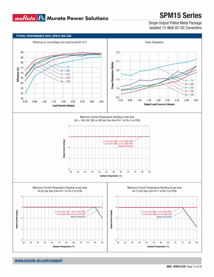
TYPICAL PERFORMANCE DATA, SPM15-050-Q48
45
50
55
60
65
70
75
80
85
90
0.35 0.68 1.02 1.35 1.69 2.02 2.35 2.68 3.02
Effi
cie
ncy (
%)
Load Current (Amps)
VIN = 75VVIN = 48VVIN = 36VVIN = 24VVIN = 18V
Maximum Current Temperature Derating at sea levelVin = 18V, 24V, 36V, or 48V (air fl ow from Pin 1 to Pin 2 on PCB)
Maximum Current Temperature Derating at sea levelVin 60 (air fl ow from Pin 1 to Pin 2 on PCB)
Maximum Current Temperature Derating at sea levelVin 75 (air fl ow from Pin 1 to Pin 2 on PCB)
0
1
2
3
4
30 35 40 45 50 55 60 65 70 75 80 85
Ou
tpu
t C
urr
en
t (A
mp
s)
Ambient Temperature (°C)
0.5 m/s (100 LFM); 1.0 m/s (200 LFM);1.5 m/s (300 LFM); 2.0 m/s (400 LFM);
Natural Convection
0
1
2
3
4
30 35 40 45 50 55 60 65 70 75 80 85
Ou
tpu
t C
urr
en
t (A
mp
s)
Ambient Temperature (°C)
0.5 m/s (100 LFM); 1.0 m/s (200 LFM);1.5 m/s (300 LFM); 2.0 m/s (400 LFM)
Natural Convection
0
1
2
3
4
30 35 40 45 50 55 60 65 70 75 80 85
Ou
tpu
t C
urr
en
t (A
mp
s)
Ambient Temperature (°C)
0.5 m/s (100 LFM); 1.0 m/s (200 LFM);1.5 m/s (300 LFM); 2.0 m/s (400 LFM)
Natural Convection
Effi ciency vs. Line Voltage and Load Current @ 25°C Power Dissipation
0.5
1.0
1.5
2.0
2.5
3.0
0.35 0.68 1.02 1.35 1.69 2.02 2.35 2.68 3.02
Output Load Current (Amps)
Pow
er
Dis
sip
ati
on
(W
att
s)
VIN = 75VVIN = 48VVIN = 36VVIN = 24VVIN = 18V
SPM15 SeriesSingle Output Potted Metal Package Isolated 15-Watt DC-DC Converters
MDC_SPM15.C04 Page 16 of 36
www.murata-ps.com/support
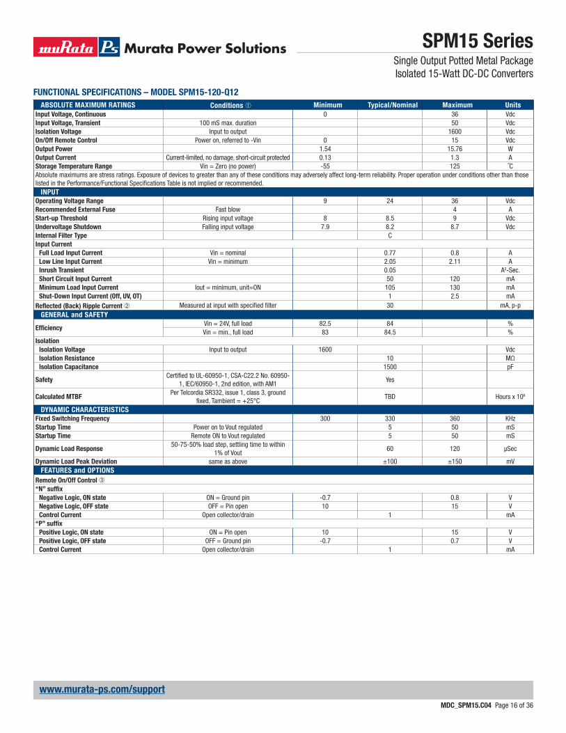
FUNCTIONAL SPECIFICATIONS – MODEL SPM15-120-Q12
ABSOLUTE MAXIMUM RATINGS Conditions ➀ Minimum Typical/Nominal Maximum Units
Input Voltage, Continuous 0 36 VdcInput Voltage, Transient 100 mS max. duration 50 VdcIsolation Voltage Input to output 1600 VdcOn/Off Remote Control Power on, referred to -Vin 0 15 VdcOutput Power 1.54 15.76 WOutput Current Current-limited, no damage, short-circuit protected 0.13 1.3 AStorage Temperature Range Vin = Zero (no power) -55 125 ˚CAbsolute maximums are stress ratings. Exposure of devices to greater than any of these conditions may adversely affect long-term reliability. Proper operation under conditions other than those listed in the Performance/Functional Specifi cations Table is not implied or recommended.
INPUT
Operating Voltage Range 9 24 36 VdcRecommended External Fuse Fast blow 4 AStart-up Threshold Rising input voltage 8 8.5 9 VdcUndervoltage Shutdown Falling input voltage 7.9 8.2 8.7 VdcInternal Filter Type CInput Current
Full Load Input Current Vin = nominal 0.77 0.8 ALow Line Input Current Vin = minimum 2.05 2.11 AInrush Transient 0.05 A2-Sec.Short Circuit Input Current 50 120 mAMinimum Load Input Current Iout = minimum, unit=ON 105 130 mAShut-Down Input Current (Off, UV, OT) 1 2.5 mA
Refl ected (Back) Ripple Current ➁ Measured at input with specifi ed fi lter 30 mA, p-pGENERAL and SAFETY
Effi ciencyVin = 24V, full load 82.5 84 %Vin = min., full load 83 84.5 %
Isolation
Isolation Voltage Input to output 1600 VdcIsolation Resistance 10 MΩIsolation Capacitance 1500 pF
SafetyCertifi ed to UL-60950-1, CSA-C22.2 No. 60950-
1, IEC/60950-1, 2nd edition, with AM1Yes
Calculated MTBFPer Telcordia SR332, issue 1, class 3, ground
fi xed, Tambient = +25°CTBD Hours x 106
DYNAMIC CHARACTERISTICS
Fixed Switching Frequency 300 330 360 KHzStartup Time Power on to Vout regulated 5 50 mSStartup Time Remote ON to Vout regulated 5 50 mS
Dynamic Load Response50-75-50% load step, settling time to within
1% of Vout60 120 μSec
Dynamic Load Peak Deviation same as above ±100 ±150 mVFEATURES and OPTIONS
Remote On/Off Control ➂“N” suffi x
Negative Logic, ON state ON = Ground pin -0.7 0.8 VNegative Logic, OFF state OFF = Pin open 10 15 VControl Current Open collector/drain 1 mA
“P” suffi x
Positive Logic, ON state ON = Pin open 10 15 VPositive Logic, OFF state OFF = Ground pin -0.7 0.7 VControl Current Open collector/drain 1 mA

SPM15 SeriesSingle Output Potted Metal Package Isolated 15-Watt DC-DC Converters
MDC_SPM15.C04 Page 17 of 36
www.murata-ps.com/support
OUTPUT Conditions ➀ ➂ Minimum Typical/Nominal Maximum Units
Total Output Power 1.54 15.6 15.76 WVoltage
Nominal Output Voltage No trim 11.88 12 12.12 VdcSetting Accuracy At 50% load, no trim -1 1 % of VnomOutput Voltage Range User-adjustable -10 10 % of Vnom.Overvoltage Protection Via magnetic feedback 15.5 17.2 19.5 Vdc
Current
Output Current Range 0.13 1.3 1.3 ACurrent Limit Inception 98% of Vnom., after warmup 1.5 2.1 2.6 A
Short Circuit
Short Circuit CurrentHiccup technique, autorecovery within
±1.25% of Vout0.3 A
Short Circuit Duration (remove short for
recovery)Output shorted to ground, no damage Continuous
Short circuit protection method Current limitingRegulation
Line Regulation Vin = min. to max., Vout = nom., Iout = nom. ±0.05 % of VoutLoad Regulation Iout = min. to max., Vin = 24V ±0.1 % of Vout
Ripple and Noise 5 Hz- 20 MHz BW, Vin=24V 60 120 mV pk-pkTemperature Coeffi cient At all outputs ±0.02 % of Vnom./°CMaximum Capacitive Loading Low ESR 470 μF
MECHANICAL
Outline Dimensions 1 x 1 x 0.41 Inches(Please refer to outline drawing) WxLxH 25.4 x 25.4 x 10.41 mm
Weight 0.69 Ounces19.56 Grams
Through Hole Pin Diameter 0.04 Inches1.016 mm
Through Hole Pin Material Copper alloyTH Pin Plating Metal and Thickness Nickel subplate 50 μ-inches
Gold overplate 5 μ-inchesENVIRONMENTAL
Operating Ambient Temperature Range See derating -40 85 °COperating Case Temperature Range No derating -40 105 °CCase Material Tin plated steel with black powder coatStorage Temperature Vin = Zero (no power) -55 125 °CThermal Protection/Shutdown Measured in center 110 115 120 °CElectromagnetic Interference External fi lter is required
Conducted, EN55022/CISPR22 B ClassRoHS rating RoHS-6
FUNCTIONAL SPECIFICATIONS (CONT.) – MODEL SPM15-120-Q12
Notes➀ Unless otherwise noted, all specifi cations are at nominal input voltage, nominal out-
put voltage and full load. General conditions are +25˚ Celsius ambient temperature, near sea level altitude, natural convection airfl ow. All models are tested and specifi ed with external parallel 1 μF and 10 μF output capacitors. The external input capacitor is 100 μF, electrolytic. All capacitors are low-ESR types wired close to the converter.
➁ Input (back) ripple current is tested and specifi ed over 5 Hz to 20 MHz bandwidth. Input fi ltering is Cbus=220 μF, Cin=33 μF and Lbus=12 μH.
➂ The Remote On/Off Control is referred to -Vin.
SPM15 SeriesSingle Output Potted Metal Package Isolated 15-Watt DC-DC Converters
MDC_SPM15.C04 Page 18 of 36
www.murata-ps.com/support
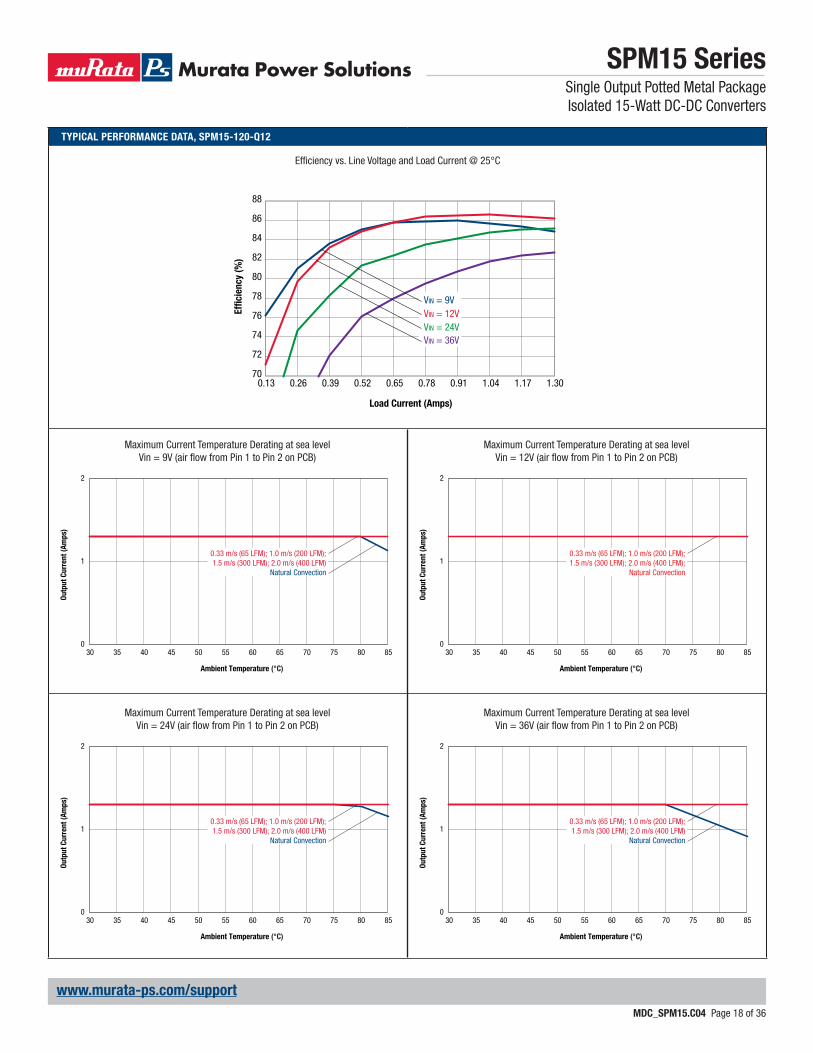
TYPICAL PERFORMANCE DATA, SPM15-120-Q12
Effi ciency vs. Line Voltage and Load Current @ 25°C
70
72
74
76
78
80
82
84
86
88
0.13 0.26 0.39 0.52 0.65 0.78 0.91 1.04 1.17 1.30
VIN = 9VVIN = 12VVIN = 24VVIN = 36V
Effi
cie
ncy (
%)
Load Current (Amps)
Maximum Current Temperature Derating at sea levelVin = 9V (air fl ow from Pin 1 to Pin 2 on PCB)
Maximum Current Temperature Derating at sea levelVin = 24V (air fl ow from Pin 1 to Pin 2 on PCB)
Maximum Current Temperature Derating at sea levelVin = 12V (air fl ow from Pin 1 to Pin 2 on PCB)
Maximum Current Temperature Derating at sea levelVin = 36V (air fl ow from Pin 1 to Pin 2 on PCB)
0
1
2
30 35 40 45 50 55 60 65 70 75 80 85
Ou
tpu
t C
urr
en
t (A
mp
s)
Ambient Temperature (°C)
0.33 m/s (65 LFM); 1.0 m/s (200 LFM);1.5 m/s (300 LFM); 2.0 m/s (400 LFM)
Natural Convection
0
1
2
30 35 40 45 50 55 60 65 70 75 80 85
Ou
tpu
t C
urr
en
t (A
mp
s)
Ambient Temperature (°C)
0.33 m/s (65 LFM); 1.0 m/s (200 LFM);1.5 m/s (300 LFM); 2.0 m/s (400 LFM)
Natural Convection
0
1
2
30 35 40 45 50 55 60 65 70 75 80 85
Ou
tpu
t C
urr
en
t (A
mp
s)
Ambient Temperature (°C)
0.33 m/s (65 LFM); 1.0 m/s (200 LFM);1.5 m/s (300 LFM); 2.0 m/s (400 LFM);
Natural Convection
0
1
2
30 35 40 45 50 55 60 65 70 75 80 85
Ou
tpu
t C
urr
en
t (A
mp
s)
Ambient Temperature (°C)
0.33 m/s (65 LFM); 1.0 m/s (200 LFM);1.5 m/s (300 LFM); 2.0 m/s (400 LFM)
Natural Convection
SPM15 SeriesSingle Output Potted Metal PackageIsolated 15-Watt DC-DC Converters
MDC_SPM15.C04 Page 19 of 36
www.murata-ps.com/support
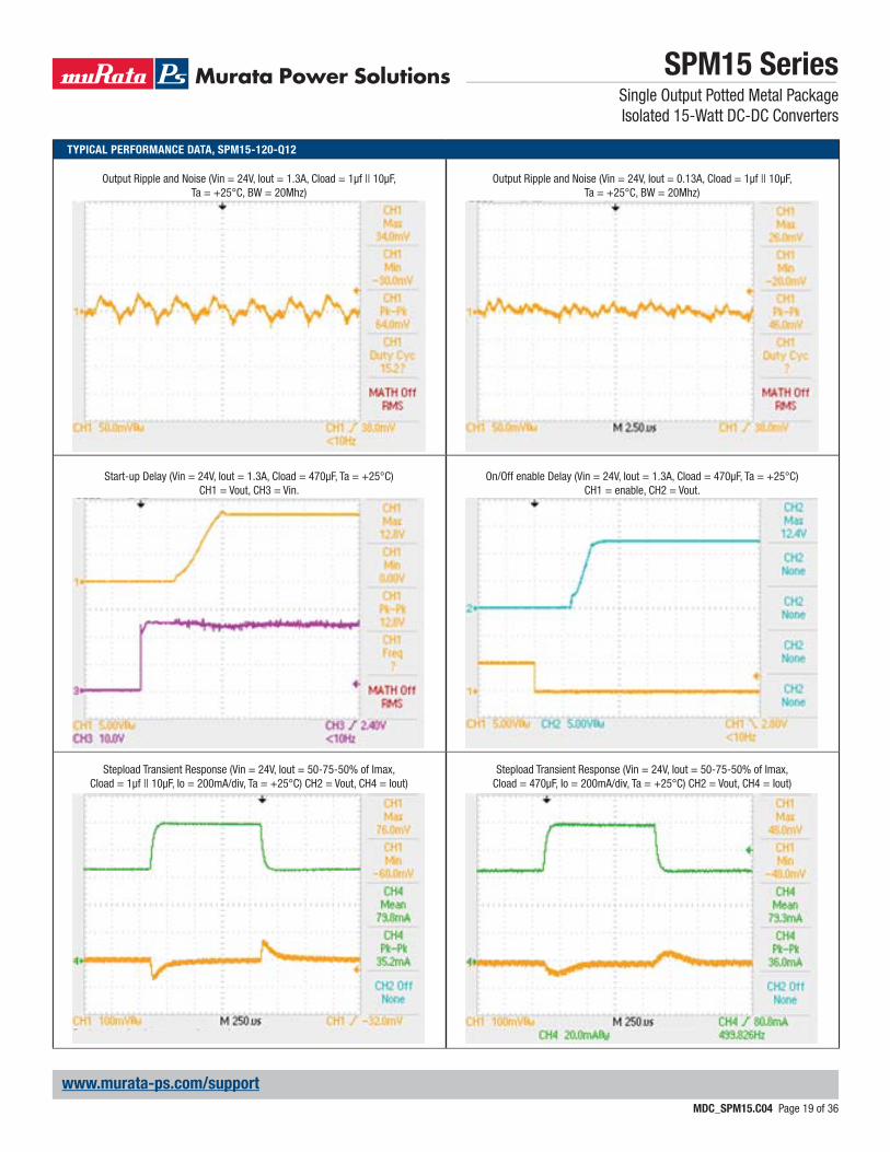
TYPICAL PERFORMANCE DATA, SPM15-120-Q12
Start-up Delay (Vin = 24V, Iout = 1.3A, Cload = 470μF, Ta = +25°C) CH1 = Vout, CH3 = Vin.
Output Ripple and Noise (Vin = 24V, Iout = 1.3A, Cload = 1μf || 10μF, Ta = +25°C, BW = 20Mhz)
Stepload Transient Response (Vin = 24V, Iout = 50-75-50% of Imax, Cload = 1μf || 10μF, Io = 200mA/div, Ta = +25°C) CH2 = Vout, CH4 = Iout)
On/Off enable Delay (Vin = 24V, Iout = 1.3A, Cload = 470μF, Ta = +25°C) CH1 = enable, CH2 = Vout.
Output Ripple and Noise (Vin = 24V, Iout = 0.13A, Cload = 1μf || 10μF, Ta = +25°C, BW = 20Mhz)
Stepload Transient Response (Vin = 24V, Iout = 50-75-50% of Imax, Cload = 470μF, Io = 200mA/div, Ta = +25°C) CH2 = Vout, CH4 = Iout)
SPM15 SeriesSingle Output Potted Metal Package Isolated 15-Watt DC-DC Converters
MDC_SPM15.C04 Page 20 of 36
www.murata-ps.com/support
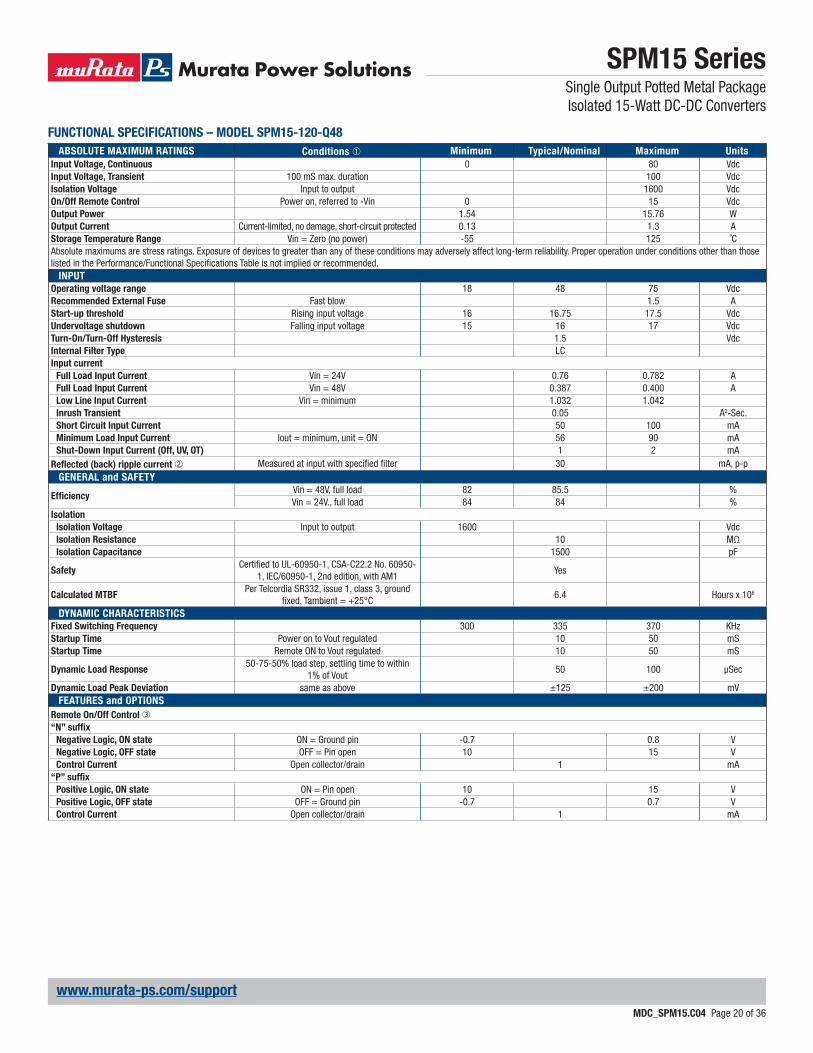
FUNCTIONAL SPECIFICATIONS – MODEL SPM15-120-Q48
ABSOLUTE MAXIMUM RATINGS Conditions ➀ Minimum Typical/Nominal Maximum Units
Input Voltage, Continuous 0 80 VdcInput Voltage, Transient 100 mS max. duration 100 VdcIsolation Voltage Input to output 1600 VdcOn/Off Remote Control Power on, referred to -Vin 0 15 VdcOutput Power 1.54 15.76 WOutput Current Current-limited, no damage, short-circuit protected 0.13 1.3 AStorage Temperature Range Vin = Zero (no power) -55 125 ˚CAbsolute maximums are stress ratings. Exposure of devices to greater than any of these conditions may adversely affect long-term reliability. Proper operation under conditions other than those listed in the Performance/Functional Specifi cations Table is not implied or recommended.
INPUT
Operating voltage range 18 48 75 VdcRecommended External Fuse Fast blow 1.5 AStart-up threshold Rising input voltage 16 16.75 17.5 VdcUndervoltage shutdown Falling input voltage 15 16 17 VdcTurn-On/Turn-Off Hysteresis 1.5 VdcInternal Filter Type LCInput current
Full Load Input Current Vin = 24V 0.76 0.782 AFull Load Input Current Vin = 48V 0.387 0.400 ALow Line Input Current Vin = minimum 1.032 1.042Inrush Transient 0.05 A2-Sec.Short Circuit Input Current 50 100 mAMinimum Load Input Current Iout = minimum, unit = ON 56 90 mAShut-Down Input Current (Off, UV, OT) 1 2 mA
Refl ected (back) ripple current ➁ Measured at input with specifi ed fi lter 30 mA, p-pGENERAL and SAFETY
Effi ciencyVin = 48V, full load 82 85.5 %Vin = 24V., full load 84 84 %
Isolation
Isolation Voltage Input to output 1600 VdcIsolation Resistance 10 MΩIsolation Capacitance 1500 pF
SafetyCertifi ed to UL-60950-1, CSA-C22.2 No. 60950-
1, IEC/60950-1, 2nd edition, with AM1Yes
Calculated MTBFPer Telcordia SR332, issue 1, class 3, ground
fi xed, Tambient = +25°C6.4 Hours x 106
DYNAMIC CHARACTERISTICS
Fixed Switching Frequency 300 335 370 KHzStartup Time Power on to Vout regulated 10 50 mSStartup Time Remote ON to Vout regulated 10 50 mS
Dynamic Load Response50-75-50% load step, settling time to within
1% of Vout50 100 μSec
Dynamic Load Peak Deviation same as above ±125 ±200 mVFEATURES and OPTIONS
Remote On/Off Control ➂“N” suffi x
Negative Logic, ON state ON = Ground pin -0.7 0.8 VNegative Logic, OFF state OFF = Pin open 10 15 VControl Current Open collector/drain 1 mA
“P” suffi x
Positive Logic, ON state ON = Pin open 10 15 VPositive Logic, OFF state OFF = Ground pin -0.7 0.7 VControl Current Open collector/drain 1 mA
SPM15 SeriesSingle Output Potted Metal Package Isolated 15-Watt DC-DC Converters
MDC_SPM15.C04 Page 21 of 36
www.murata-ps.com/support
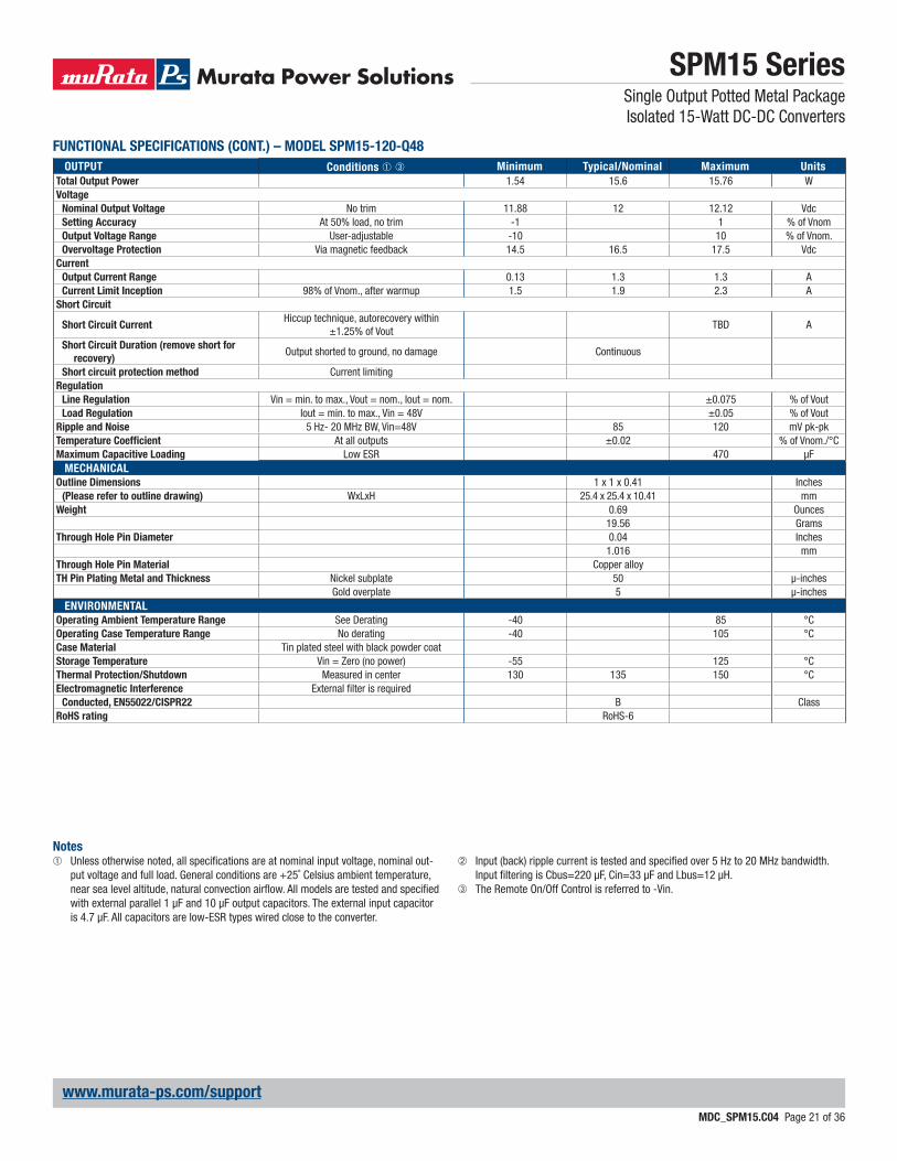
FUNCTIONAL SPECIFICATIONS (CONT.) – MODEL SPM15-120-Q48
OUTPUT Conditions ➀ ➂ Minimum Typical/Nominal Maximum Units
Total Output Power 1.54 15.6 15.76 WVoltage
Nominal Output Voltage No trim 11.88 12 12.12 VdcSetting Accuracy At 50% load, no trim -1 1 % of VnomOutput Voltage Range User-adjustable -10 10 % of Vnom.Overvoltage Protection Via magnetic feedback 14.5 16.5 17.5 Vdc
Current
Output Current Range 0.13 1.3 1.3 ACurrent Limit Inception 98% of Vnom., after warmup 1.5 1.9 2.3 A
Short Circuit
Short Circuit CurrentHiccup technique, autorecovery within
±1.25% of VoutTBD A
Short Circuit Duration (remove short for
recovery)Output shorted to ground, no damage Continuous
Short circuit protection method Current limitingRegulation
Line Regulation Vin = min. to max., Vout = nom., Iout = nom. ±0.075 % of VoutLoad Regulation Iout = min. to max., Vin = 48V ±0.05 % of Vout
Ripple and Noise 5 Hz- 20 MHz BW, Vin=48V 85 120 mV pk-pkTemperature Coeffi cient At all outputs ±0.02 % of Vnom./°CMaximum Capacitive Loading Low ESR 470 μF
MECHANICAL
Outline Dimensions 1 x 1 x 0.41 Inches(Please refer to outline drawing) WxLxH 25.4 x 25.4 x 10.41 mm
Weight 0.69 Ounces19.56 Grams
Through Hole Pin Diameter 0.04 Inches1.016 mm
Through Hole Pin Material Copper alloyTH Pin Plating Metal and Thickness Nickel subplate 50 μ-inches
Gold overplate 5 μ-inchesENVIRONMENTAL
Operating Ambient Temperature Range See Derating -40 85 °COperating Case Temperature Range No derating -40 105 °CCase Material Tin plated steel with black powder coatStorage Temperature Vin = Zero (no power) -55 125 °CThermal Protection/Shutdown Measured in center 130 135 150 °CElectromagnetic Interference External fi lter is required
Conducted, EN55022/CISPR22 B ClassRoHS rating RoHS-6
Notes➀ Unless otherwise noted, all specifi cations are at nominal input voltage, nominal out-
put voltage and full load. General conditions are +25˚ Celsius ambient temperature, near sea level altitude, natural convection airfl ow. All models are tested and specifi ed with external parallel 1 μF and 10 μF output capacitors. The external input capacitor is 4.7 μF. All capacitors are low-ESR types wired close to the converter.
➁ Input (back) ripple current is tested and specifi ed over 5 Hz to 20 MHz bandwidth. Input fi ltering is Cbus=220 μF, Cin=33 μF and Lbus=12 μH.
➂ The Remote On/Off Control is referred to -Vin.
SPM15 SeriesSingle Output Potted Metal Package Isolated 15-Watt DC-DC Converters
MDC_SPM15.C04 Page 22 of 36
www.murata-ps.com/support
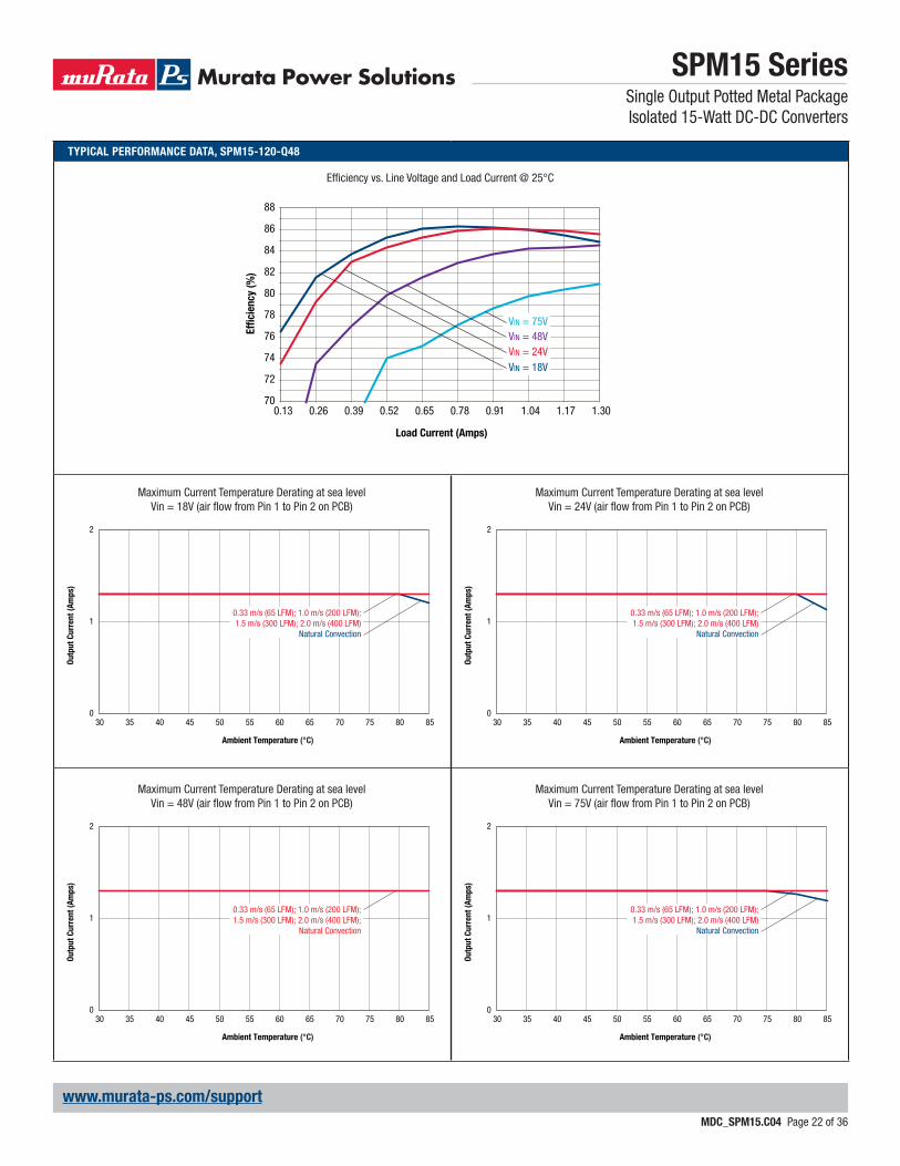
TYPICAL PERFORMANCE DATA, SPM15-120-Q48
Effi ciency vs. Line Voltage and Load Current @ 25°C
Maximum Current Temperature Derating at sea levelVin = 18V (air fl ow from Pin 1 to Pin 2 on PCB)
Maximum Current Temperature Derating at sea levelVin = 48V (air fl ow from Pin 1 to Pin 2 on PCB)
Maximum Current Temperature Derating at sea levelVin = 24V (air fl ow from Pin 1 to Pin 2 on PCB)
Maximum Current Temperature Derating at sea levelVin = 75V (air fl ow from Pin 1 to Pin 2 on PCB)
0
1
2
30 35 40 45 50 55 60 65 70 75 80 85
Ou
tpu
t C
urr
en
t (A
mp
s)
Ambient Temperature (°C)
0.33 m/s (65 LFM); 1.0 m/s (200 LFM);1.5 m/s (300 LFM); 2.0 m/s (400 LFM)
Natural Convection
0
1
2
30 35 40 45 50 55 60 65 70 75 80 85
Ou
tpu
t C
urr
en
t (A
mp
s)
Ambient Temperature (°C)
0.33 m/s (65 LFM); 1.0 m/s (200 LFM);1.5 m/s (300 LFM); 2.0 m/s (400 LFM);
Natural Convection
0
1
2
30 35 40 45 50 55 60 65 70 75 80 85
Ou
tpu
t C
urr
en
t (A
mp
s)
Ambient Temperature (°C)
0.33 m/s (65 LFM); 1.0 m/s (200 LFM);1.5 m/s (300 LFM); 2.0 m/s (400 LFM)
Natural Convection
0
1
2
30 35 40 45 50 55 60 65 70 75 80 85
Ou
tpu
t C
urr
en
t (A
mp
s)
Ambient Temperature (°C)
0.33 m/s (65 LFM); 1.0 m/s (200 LFM);1.5 m/s (300 LFM); 2.0 m/s (400 LFM)
Natural Convection
70
72
74
76
78
80
82
84
86
88
0.13 0.26 0.39 0.52 0.65 0.78 0.91 1.04 1.17 1.30
Effi
cie
ncy (
%)
Load Current (Amps)
VIN = 75VVIN = 48VVIN = 24VVIN = 18V
SPM15 SeriesSingle Output Potted Metal Package Isolated 15-Watt DC-DC Converters
MDC_SPM15.C04 Page 23 of 36
www.murata-ps.com/support
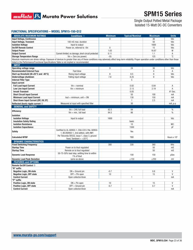
FUNCTIONAL SPECIFICATIONS – MODEL SPM15-150-Q12
ABSOLUTE MAXIMUM RATINGS Conditions ➀ Minimum Typical/Nominal Maximum Units
Input Voltage, Continuous 0 36 VdcInput Voltage, Transient 100 mS max. duration 50 VdcIsolation Voltage Input to output 1600 VdcOn/Off Remote Control Power on, referred to -Vin 0 15 VdcOutput Power 1.63 16.67 WOutput Current Current-limited, no damage, short-circuit protected 0.11 1.1 AStorage Temperature Range Vin = Zero (no power) -55 125 ˚CAbsolute maximums are stress ratings. Exposure of devices to greater than any of these conditions may adversely affect long-term reliability. Proper operation under conditions other than those listed in the Performance/Functional Specifi cations Table is not implied or recommended.
INPUT
Operating voltage range 9 24 36 VdcRecommended External Fuse Fast blow 4 AStart-up threshold (@+25°C and -40°C) Rising input voltage 8 8.5 9 VdcUndervoltage shutdown Falling input voltage 7.8 8.25 9 VdcInternal Filter Type CInput current
Full Load Input Current Vin = nominal 0.82 0.84 ALow Line Input Current Vin = minimum 2.13 2.19 AInrush Transient 0.05 A2-Sec.Short Circuit Input Current 50 100 mAMinimum Load Input Current Iout = minimum, unit = ON 130 150 mAShut-Down Input Current (Off, UV, OT) 1 2.5 mA
Refl ected (back) ripple current ➁ Measured at input with specifi ed fi lter 30 mA, p-pGENERAL and SAFETY
Effi ciencyVin = 24V, full load 82.5 84 %Vin = min., full load 84.5 86 %
Isolation
Isolation Voltage Input to output 1600 VdcInsulation Safety Rating basicIsolation Resistance 10 MΩIsolation Capacitance 1500 pF
SafetyCertifi ed to UL-60950-1, CSA-C22.2 No. 60950-
1, IEC/60950-1, 2nd edition, with AM1Yes
Calculated MTBFPer Telcordia SR332, issue 1, class 3, ground
fi xed, Tambient = +25°CTBD Hours x 106
DYNAMIC CHARACTERISTICS
Fixed Switching Frequency 300 330 360 KHzStartup Time Power on to Vout regulated 50 mSStartup Time Remote on to Vout regulated 50 mS
Dynamic Load Response50-75-50% load step, settling time to within
1% of Vout100 150 μSec
Dynamic Load Peak Deviation same as above ±150 ±250 mVFEATURES and OPTIONS
Remote On/Off Control ➂“N” suffi x
Negative Logic, ON state ON = Ground pin -0.7 0.8 VNegative Logic, OFF state OFF = Pin open 10 15 VControl Current Open collector/drain 1 mA
“P” suffi x
Positive Logic, ON state ON = Pin open 10 15 VPositive Logic, OFF state OFF = Ground pin -0.7 0.7 VControl Current Open collector/drain 1 mA

SPM15 SeriesSingle Output Potted Metal Package Isolated 15-Watt DC-DC Converters
MDC_SPM15.C04 Page 24 of 36
www.murata-ps.com/support
FUNCTIONAL SPECIFICATIONS (CONT.) – MODEL SPM15-150-Q12
OUTPUT Conditions ➀ ➂ Minimum Typical/Nominal Maximum Units
Total Output Power 1.63 16.5 16.67 WVoltage
Nominal Output Voltage No trim 14.85 15 15.15 VdcSetting Accuracy At 50% load, no trim 1 1 % of VnomOutput Voltage Range User-adjustable -10 10 % of Vnom.Overvoltage Protection Via magnetic feedback 17 19.5 22.5 Vdc
Current
Output Current Range 0.11 1.1 1.1 ACurrent Limit Inception 98% of Vnom., after warmup 1.2 1.6 2 A
Short Circuit
Short Circuit CurrentHiccup technique, autorecovery within
±1.25% of Vout0.3 A
Short Circuit Duration (remove short for
recovery)Output shorted to ground, no damage Continuous
Short circuit protection method Current limitingRegulation
Line Regulation Vin = min. to max., Vout = nom., Iout = nom. ±0.1 % of VoutLoad Regulation Iout = min. to max., Vin = 24V ±0.1 % of Vout
Ripple and Noise 5 Hz- 20 MHz BW, Vin=24V 130 175 mV pk-pkTemperature Coeffi cient At all outputs ±0.02 % of Vnom./°CMaximum Capacitive Loading Low ESR 470 μF
MECHANICAL
Outline Dimensions 1 x 1 x 0.41 Inches(Please refer to outline drawing) WxLxH 25.4 x 25.4 x 10.41 mm
Weight 0.69 Ounces19.56 Grams
Through Hole Pin Diameter 0.04 Inches1.016 mm
Through Hole Pin Material Copper alloyTH Pin Plating Metal and Thickness Nickel subplate 50 μ-inches
Gold overplate 5 μ-inchesENVIRONMENTAL
Operating Ambient Temperature Range See Derating -40 85 °COperating Case Temperature Range No derating -40 105 °CCase Material Tin plated steel with black powder coatStorage Temperature Vin = Zero (no power) -55 125 °CThermal Protection/Shutdown Measured in center 110 115 120 °CElectromagnetic Interference External fi lter is required
Conducted, EN55022/CISPR22 B ClassRoHS rating RoHS-6
Notes➀ Unless otherwise noted, all specifi cations are at nominal input voltage, nominal out-
put voltage and full load. General conditions are +25˚ Celsius ambient temperature, near sea level altitude, natural convection airfl ow. All models are tested and specifi ed with external parallel 1 μF and 10 μF output capacitors. The external input capacitor is 100 μF, electrolytic. All capacitors are low-ESR types wired close to the converter.
➁ Input (back) ripple current is tested and specifi ed over 5 Hz to 20 MHz bandwidth. Input fi ltering is Cbus=220 μF, Cin=33 μF and Lbus=12 μH.
➂ The Remote On/Off Control is referred to -Vin.
SPM15 SeriesSingle Output Potted Metal Package Isolated 15-Watt DC-DC Converters
MDC_SPM15.C04 Page 25 of 36
www.murata-ps.com/support
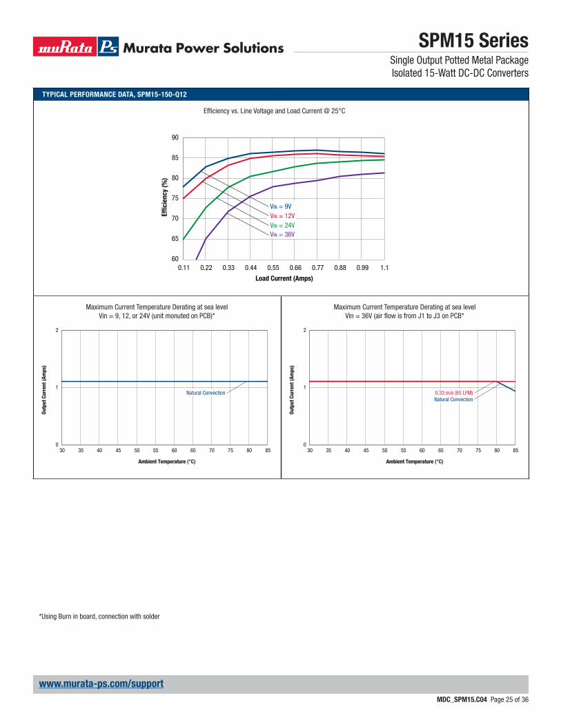
TYPICAL PERFORMANCE DATA, SPM15-150-Q12
Effi ciency vs. Line Voltage and Load Current @ 25°C
60
65
70
75
80
85
90
0.11 0.22 0.33 0.44 0.55 0.66 0.77 0.88 0.99 1.1
VIN = 9VVIN = 12VVIN = 24VVIN = 36V
Effi
cie
ncy (
%)
Load Current (Amps)
Maximum Current Temperature Derating at sea levelVin = 9, 12, or 24V (unit monuted on PCB)*
Maximum Current Temperature Derating at sea levelVin = 36V (air fl ow is from J1 to J3 on PCB*
0
1
2
30 35 40 45 50 55 60 65 70 75 80 85
Ou
tpu
t C
urr
en
t (A
mp
s)
Ambient Temperature (°C)
Natural Convection
0
1
2
30 35 40 45 50 55 60 65 70 75 80 85
Ou
tpu
t C
urr
en
t (A
mp
s)
Ambient Temperature (°C)
0.33 m/s (65 LFM)Natural Convection
*Using Burn in board, connection with solder
SPM15 SeriesSingle Output Potted Metal PackageIsolated 15-Watt DC-DC Converters
MDC_SPM15.C04 Page 26 of 36
www.murata-ps.com/support
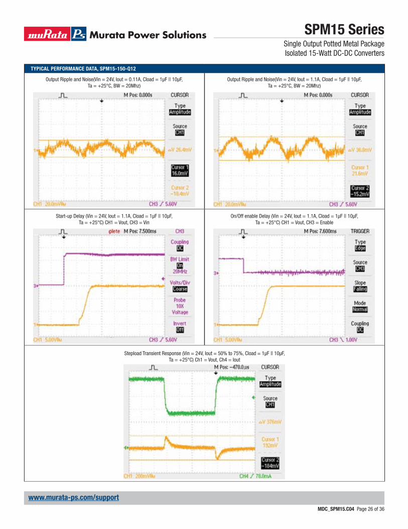
TYPICAL PERFORMANCE DATA, SPM15-150-Q12
Start-up Delay (Vin = 24V, Iout = 1.1A, Cload = 1μF || 10μF, Ta = +25°C) CH1 = Vout, CH3 = Vin
Output Ripple and Noise(Vin = 24V, Iout = 0.11A, Cload = 1μF || 10μF, Ta = +25°C, BW = 20Mhz)
Stepload Transient Response (Vin = 24V, Iout = 50% to 75%, Cload = 1μF || 10μF, Ta = +25°C) Ch1 = Vout, Ch4 = Iout
On/Off enable Delay (Vin = 24V, Iout = 1.1A, Cload = 1μF || 10μF, Ta = +25°C) CH1 = Vout, CH3 = Enable
Output Ripple and Noise(Vin = 24V, Iout = 1.1A, Cload = 1μF || 10μF, Ta = +25°C, BW = 20Mhz)

SPM15 SeriesSingle Output Potted Metal Package Isolated 15-Watt DC-DC Converters
MDC_SPM15.C04 Page 27 of 36
www.murata-ps.com/support
FUNCTIONAL SPECIFICATIONS – MODEL SPM15-150-Q48
ABSOLUTE MAXIMUM RATINGS Conditions ➀ Minimum Typical/Nominal Maximum Units
Input Voltage, Continuous 0 80 VdcInput Voltage, Transient 100 mS max. duration 100 VdcIsolation Voltage Input to output 1600 VdcOn/Off Remote Control Power on, referred to -Vin 0 15 VdcOutput Power 1.63 16.67 WOutput Current Current-limited, no damage, short-circuit protected 0.11 1.1 AStorage Temperature Range Vin = Zero (no power) -55 125 ˚CAbsolute maximums are stress ratings. Exposure of devices to greater than any of these conditions may adversely affect long-term reliability. Proper operation under conditions other than those listed in the Performance/Functional Specifi cations Table is not implied or recommended.
INPUT
Operating voltage range 18 48 75 VdcRecommended External Fuse Fast blow 2 AStart-up threshold Rising input voltage 16 16.7 17.9 VdcUndervoltage shutdown Falling input voltage 15 16.2 17.5 VdcInternal Filter Type CInput current
Full Load Input Current Vin = nominal 0.41 0.42 ALow Line Input Current Vin = minimum 1.06 1.09 AInrush Transient 0.05 A2-Sec.Short Circuit Input Current 50 100 mAMinimum Load Input Current Iout = minimum, unit = ON 60 85 mAShut-Down Input Current (Off, UV, OT) 1 2 mA
Refl ected (back) ripple current ➁ Measured at input with specifi ed fi lter 30 mA, p-pGENERAL and SAFETY
Effi ciencyVin = 48V, full load 83 85.5 %Vin = min., full load 85 86.5 %
Isolation
Isolation Voltage Input to output 1600 VdcInsulation Safety Rating basicIsolation Resistance 10 MΩIsolation Capacitance 1500 pF
SafetyCertifi ed to UL-60950-1, CSA-C22.2 No. 60950-
1, IEC/60950-1, 2nd edition, with AM1Yes
Calculated MTBFPer Telcordia SR332, issue 1, class 3, ground
fi xed, Tambient = +25°CTBD Hours x 106
DYNAMIC CHARACTERISTICS
Fixed Switching Frequency 300 330 360 KHzStartup Time Power on to Vout regulated 50 mSStartup Time Remote on to Vout regulated 50 mS
Dynamic Load Response50-75-50% load step, settling time to within
1% of Vout60 120 μSec
Dynamic Load Peak Deviation same as above ±150 ±250 mVFEATURES and OPTIONS
Remote On/Off Control ➂“N” suffi x
Negative Logic, ON state ON = Ground pin -0.7 0.8 VNegative Logic, OFF state OFF = Pin open 10 15 VControl Current Open collector/drain 1 mA
“P” suffi x
Positive Logic, ON state ON = Pin open 10 15 VPositive Logic, OFF state OFF = Ground pin -0.7 0.7 VControl Current Open collector/drain 1 mA

SPM15 SeriesSingle Output Potted Metal Package Isolated 15-Watt DC-DC Converters
MDC_SPM15.C04 Page 28 of 36
www.murata-ps.com/support
FUNCTIONAL SPECIFICATIONS (CONT.) – MODEL SPM15-150-Q48
OUTPUT Conditions ➀ ➂ Minimum Typical/Nominal Maximum Units
Total Output Power 1.63 16.5 16.67 WVoltage
Nominal Output Voltage No trim 14.85 15 15.15 VdcSetting Accuracy At 50% load, no trim 1 1 % of VnomOutput Voltage Range User-adjustable -10 10 % of Vnom.Overvoltage Protection Via magnetic feedback 19 20 21.5 Vdc
Current
Output Current Range 0.11 1.1 1.1 ACurrent Limit Inception 98% of Vnom., after warmup 1.3 1.7 2.2 A
Short Circuit
Short Circuit CurrentHiccup technique, autorecovery within
±1.25% of Vout0.3 A
Short Circuit Duration (remove short for
recovery)Output shorted to ground, no damage Continuous
Short circuit protection method Current limitingRegulation
Line Regulation Vin = min. to max., Vout = nom., Iout = nom. ±0.1 % of VoutLoad Regulation Iout = min. to max., Vin = 48V ±0.075 % of Vout
Ripple and Noise 5 Hz- 20 MHz BW, Vin=24V 80 150 mV pk-pkTemperature Coeffi cient At all outputs ±0.02 % of Vnom./°CMaximum Capacitive Loading Low ESR 470 μF
MECHANICAL
Outline Dimensions 1 x 1 x 0.41 Inches(Please refer to outline drawing) WxLxH 25.4 x 25.4 x 10.41 mm
Weight 0.69 Ounces19.56 Grams
Through Hole Pin Diameter 0.04 Inches1.016 mm
Through Hole Pin Material Copper alloyTH Pin Plating Metal and Thickness Nickel subplate 50 μ-inches
Gold overplate 5 μ-inchesENVIRONMENTAL
Operating Ambient Temperature Range See Derating -40 85 °COperating Case Temperature Range No derating -40 105 °CCase Material Tin plated steel with black powder coatStorage Temperature Vin = Zero (no power) -55 125 °CThermal Protection/Shutdown Measured in center 110 115 120 °CElectromagnetic Interference External fi lter is required
Conducted, EN55022/CISPR22 B ClassRoHS rating RoHS-6
Notes➀ Unless otherwise noted, all specifi cations are at nominal input voltage, nominal out-
put voltage and full load. General conditions are +25˚ Celsius ambient temperature, near sea level altitude, natural convection airfl ow. All models are tested and specifi ed with external parallel 1 μF and 10 μF output capacitors. The external input capacitor is 4.7 μF. All capacitors are low-ESR types wired close to the converter.
➁ Input (back) ripple current is tested and specifi ed over 5 Hz to 20 MHz bandwidth. Input fi ltering is Cbus=220 μF, Cin=33 μF and Lbus=12 μH.
➂ The Remote On/Off Control is referred to -Vin.
SPM15 SeriesSingle Output Potted Metal Package Isolated 15-Watt DC-DC Converters
MDC_SPM15.C04 Page 29 of 36
www.murata-ps.com/support
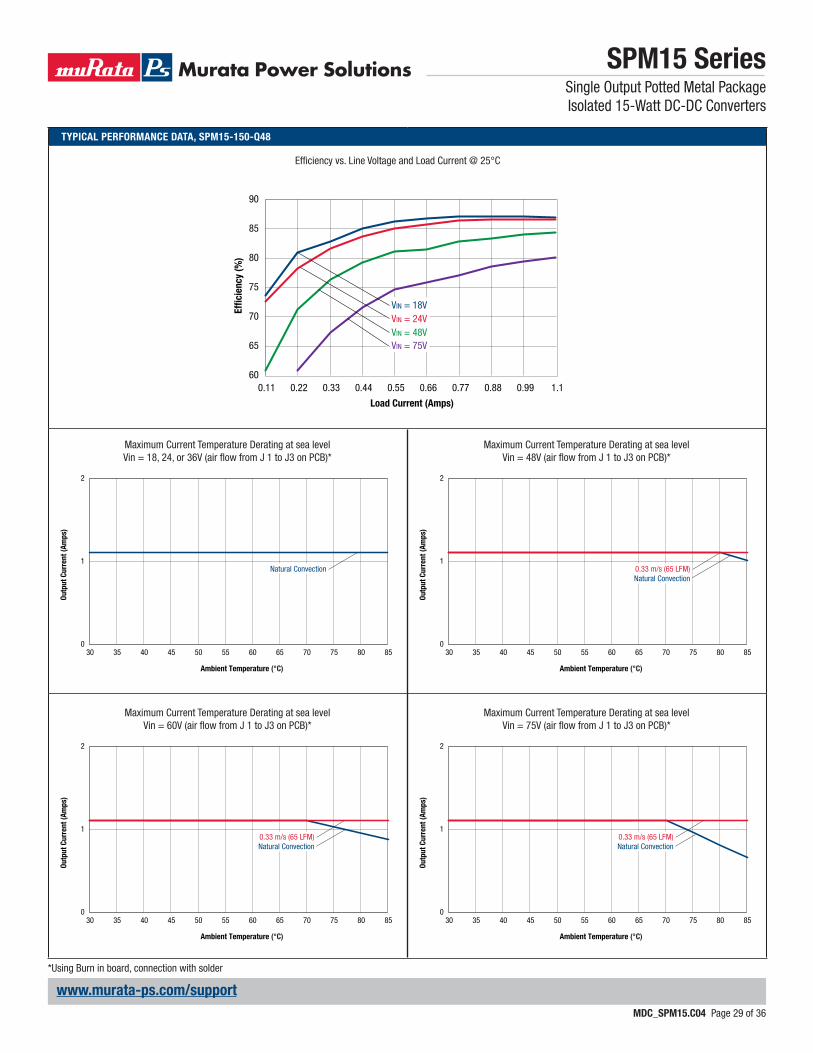
TYPICAL PERFORMANCE DATA, SPM15-150-Q48
Effi ciency vs. Line Voltage and Load Current @ 25°C
60
65
70
75
80
85
90
0.11 0.22 0.33 0.44 0.55 0.66 0.77 0.88 0.99 1.1
VIN = 18VVIN = 24VVIN = 48VVIN = 75V
Effi
cie
ncy (
%)
Load Current (Amps)
Maximum Current Temperature Derating at sea levelVin = 18, 24, or 36V (air fl ow from J 1 to J3 on PCB)*
Maximum Current Temperature Derating at sea levelVin = 60V (air fl ow from J 1 to J3 on PCB)*
Maximum Current Temperature Derating at sea levelVin = 48V (air fl ow from J 1 to J3 on PCB)*
Maximum Current Temperature Derating at sea levelVin = 75V (air fl ow from J 1 to J3 on PCB)*
0
1
2
30 35 40 45 50 55 60 65 70 75 80 85
Ou
tpu
t C
urr
en
t (A
mp
s)
Ambient Temperature (°C)
Natural Convection
0
1
2
30 35 40 45 50 55 60 65 70 75 80 85
Ou
tpu
t C
urr
en
t (A
mp
s)
Ambient Temperature (°C)
0.33 m/s (65 LFM)Natural Convection
0
1
2
30 35 40 45 50 55 60 65 70 75 80 85
Ou
tpu
t C
urr
en
t (A
mp
s)
Ambient Temperature (°C)
0.33 m/s (65 LFM)Natural Convection
0
1
2
30 35 40 45 50 55 60 65 70 75 80 85
Ou
tpu
t C
urr
en
t (A
mp
s)
Ambient Temperature (°C)
0.33 m/s (65 LFM)Natural Convection
*Using Burn in board, connection with solder
SPM15 SeriesSingle Output Potted Metal PackageIsolated 15-Watt DC-DC Converters
MDC_SPM15.C04 Page 30 of 36
www.murata-ps.com/support
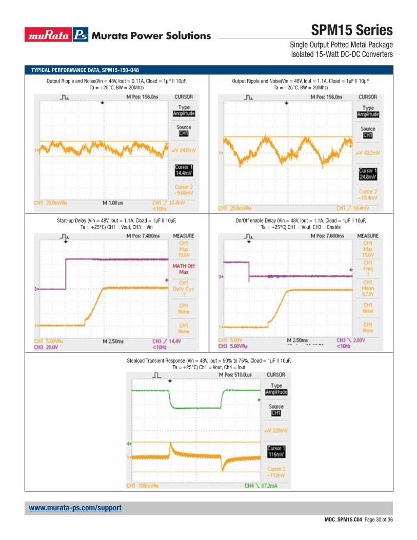
TYPICAL PERFORMANCE DATA, SPM15-150-Q48
Start-up Delay (Vin = 48V, Iout = 1.1A, Cload = 1μF || 10μF, Ta = +25°C) CH1 = Vout, CH3 = Vin
Output Ripple and Noise(Vin = 48V, Iout = 0.11A, Cload = 1μF || 10μF, Ta = +25°C, BW = 20Mhz)
Stepload Transient Response (Vin = 48V, Iout = 50% to 75%, Cload = 1μF || 10μF, Ta = +25°C) Ch1 = Vout, Ch4 = Iout
On/Off enable Delay (Vin = 48V, Iout = 1.1A, Cload = 1μF || 10μF, Ta = +25°C) CH1 = Vout, CH3 = Enable
Output Ripple and Noise(Vin = 48V, Iout = 1.1A, Cload = 1μF || 10μF, Ta = +25°C, BW = 20Mhz)
SPM15 SeriesSingle Output Potted Metal Package Isolated 15-Watt DC-DC Converters
MDC_SPM15.C04 Page 31 of 36
www.murata-ps.com/support
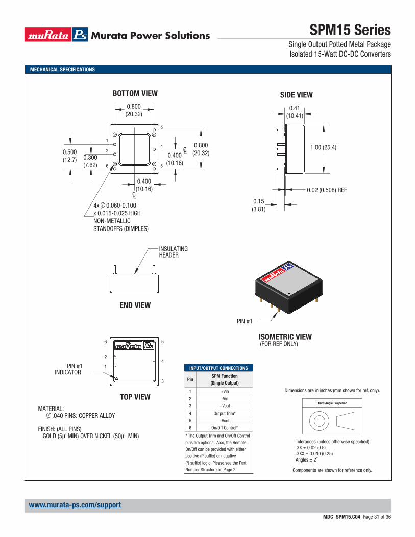
MECHANICAL SPECIFICATIONS
0.02 (0.508) REF
1.00 (25.4)
0.15(3.81)
3
6
CL
1
2
CL
5
4
x 0.015-0.025 HIGHNON-METALLICSTANDOFFS (DIMPLES)
4x 0.060-0.100
INSULATINGHEADER
2
1
56
4PIN #1
INDICATOR3
PIN #1
END VIEW
TOP VIEW
SIDE VIEW
0.41 (10.41)
MATERIAL:.040 PINS: COPPER ALLOY
FINISH: (ALL PINS) GOLD (5μ"MIN) OVER NICKEL (50μ" MIN)
BOTTOM VIEW
0.400 (10.16)
0.400 (10.16)
0.300 (7.62)
0.500 (12.7)
0.800 (20.32)
0.800 (20.32)
ISOMETRIC VIEW(FOR REF ONLY)
INPUT/OUTPUT CONNECTIONS
PinSPM Function
(Single Output)
1 +Vin
2 -Vin
3 +Vout
4 Output Trim*
5 -Vout
6 On/Off Control*
* The Output Trim and On/Off Control pins are optional. Also, the Remote On/Off can be provided with either positive (P suffi x) or negative(N suffi x) logic. Please see the Part Number Structure on Page 2.
Third Angle Projection
Dimensions are in inches (mm shown for ref. only).
Components are shown for reference only.
Tolerances (unless otherwise specified):.XX ± 0.02 (0.5).XXX ± 0.010 (0.25)Angles ± 2˚
SPM15 SeriesSingle Output Potted Metal Package Isolated 15-Watt DC-DC Converters
MDC_SPM15.C04 Page 32 of 36
www.murata-ps.com/support
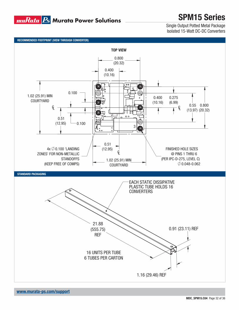
RECOMMENDED FOOTPRINT (VIEW THROUGH CONVERTER)
STANDARD PACKAGING
0.100
0.100
FINISHED HOLE SIZES@ PINS 1 THRU 6
(PER IPC-D-275, LEVEL C) 0.048-0.062
1.02 (25.91) MINCOURTYARD
1.02 (25.91) MINCOURTYARD
0.51(12.95)
0.51(12.95)
4x 0.100 'LANDINGZONES' FOR NON-METALLIC
STANDOFFS(KEEP FREE OF COMPS)
0.55(13.97)
0.275(6.99)
CL
CLCL1
2
6 5
4
3
TOP VIEW
0.400 (10.16)
0.400 (10.16)
0.800 (20.32)
0.800 (20.32)
16 UNITS PER TUBE6 TUBES PER CARTON
EACH STATIC DISSIPATIVE PLASTIC TUBE HOLDS 16 CONVERTERS
21.88(555.75)
REF
1.16 (29.46) REF
0.91 (23.11) REF
SPM15 SeriesSingle Output Potted Metal Package Isolated 15-Watt DC-DC Converters
MDC_SPM15.C04 Page 33 of 36
www.murata-ps.com/support
Input Fusing
Certain applications and/or safety agencies may require fuses at the inputs of power conversion components. Fuses should also be used when there is the possibility of sustained input voltage reversal which is not current-limited. For greatest safety, we recommend a fast blow fuse installed in the ungrounded input supply line.
The installer must observe all relevant safety standards and regulations. For safety agency approvals, install the converter in compliance with the end-user safety standard.
Input Under-Voltage Shutdown and Start-Up Threshold
Under normal start-up conditions, converters will not begin to regulate properly until the rising input voltage exceeds and remains at the Start-Up Threshold Voltage (see Specifi cations). Once operating, converters will not turn off until the input voltage drops below the Under-Voltage Shutdown Limit. Subsequent restart will not occur until the input voltage rises again above the Start-Up Threshold. This built-in hysteresis prevents any unstable on/off operation at a single input voltage.
Users should be aware however of input sources near the Under-Voltage Shutdown whose voltage decays as input current is consumed (such as capacitor inputs), the converter shuts off and then restarts as the external capacitor re-charges. Such situations could oscillate. To prevent this, make sure the operating input voltage is well above the UV Shutdown voltage AT ALL TIMES.
Start-Up Delay
Assuming that the output current is set at the rated maximum, the Vin to Vout Start-Up Delay (see Specifi cations) is the time interval between the point when the rising input voltage crosses the Start-Up Threshold and the fully loaded regulated output voltage enters and remains within its specifi ed regulation band. Actual measured times will vary with input source impedance, external input capacitance, input volt-age slew rate and fi nal value of the input voltage as it appears at the converter.
These converters include a soft start circuit to moderate the duty cycle of the PWM controller at power up, thereby limiting the input inrush current.
The On/Off Remote Control interval from inception to VOUT regulated as-sumes that the converter already has its input voltage stabilized above the Start-Up Threshold before the On command. The interval is measured from the On command until the output enters and remains within its specifi ed regulation band. The specifi cation assumes that the output is fully loaded at maximum rated current.
Input Source Impedance
These converters will operate to specifi cations without external components, assuming that the source voltage has very low impedance and reasonable in-put voltage regulation. Since real-world voltage sources have fi nite impedance, performance is improved by adding external fi lter components. Sometimes only a small ceramic capacitor is suffi cient. Since it is diffi cult to totally characterize all applications, some experimentation may be needed. Note that external input capacitors must accept high speed switching currents.
TECHNICAL NOTES Because of the switching nature of DC/DC converters, the input of these converters must be driven from a source with both low AC impedance and adequate DC input regulation. Performance will degrade with increasing input inductance. Excessive input inductance may inhibit operation. The DC input regulation specifi es that the input voltage, once operating, must never degrade below the Shut-Down Threshold under all load conditions. Be sure to use adequate trace sizes and mount components close to the converter.
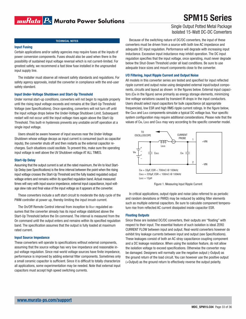
I/O Filtering, Input Ripple Current and Output Noise
All models in this converter series are tested and specifi ed for input refl ected ripple current and output noise using designated external input/output compo-nents, circuits and layout as shown in the fi gures below. External input capaci-tors (CIN in the fi gure) serve primarily as energy storage elements, minimizing line voltage variations caused by transient IR drops in the input conductors. Users should select input capacitors for bulk capacitance (at appropriate frequencies), low ESR and high RMS ripple current ratings. In the fi gure below, the CBUS and LBUS components simulate a typical DC voltage bus. Your specifi c system confi guration may require additional considerations. Please note that the values of CIN, LBUS and CBUS may vary according to the specifi c converter model.
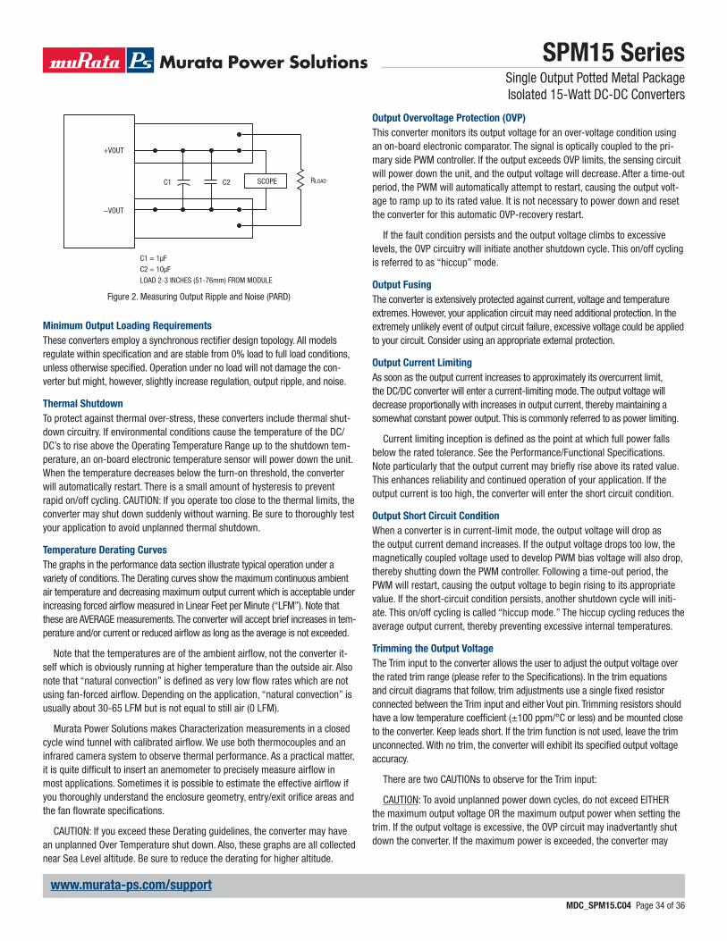
In critical applications, output ripple and noise (also referred to as periodic and random deviations or PARD) may be reduced by adding fi lter elements such as multiple external capacitors. Be sure to calculate component tempera-ture rise from refl ected AC current dissipated inside capacitor ESR.
Floating Outputs
Since these are isolated DC/DC converters, their outputs are “fl oating” with respect to their input. The essential feature of such isolation is ideal ZERO CURRENT FLOW between input and output. Real-world converters however do exhibit tiny leakage currents between input and output (see Specifi cations). These leakages consist of both an AC stray capacitance coupling component and a DC leakage resistance. When using the isolation feature, do not allow the isolation voltage to exceed specifi cations. Otherwise the converter may be damaged. Designers will normally use the negative output (-Output) as the ground return of the load circuit. You can however use the positive output (+Output) as the ground return to effectively reverse the output polarity.
CINVIN CBUS
LBUS
CIN = 33μF, ESR < 700mΩ @ 100kHz
CBUS = 220μF, ESR < 100mΩ @ 100kHz
LBUS = 12μH
1
2
+VIN
−VIN
CURRENTPROBE
TO OSCILLOSCOPE
+–+–
Figure 1. Measuring Input Ripple Current
SPM15 SeriesSingle Output Potted Metal Package Isolated 15-Watt DC-DC Converters
MDC_SPM15.C04 Page 34 of 36
www.murata-ps.com/support
Minimum Output Loading Requirements
These converters employ a synchronous rectifi er design topology. All models regulate within specifi cation and are stable from 0% load to full load conditions, unless otherwise specifi ed. Operation under no load will not damage the con-verter but might, however, slightly increase regulation, output ripple, and noise.
Thermal Shutdown
To protect against thermal over-stress, these converters include thermal shut-down circuitry. If environmental conditions cause the temperature of the DC/DC’s to rise above the Operating Temperature Range up to the shutdown tem-perature, an on-board electronic temperature sensor will power down the unit. When the temperature decreases below the turn-on threshold, the converter will automatically restart. There is a small amount of hysteresis to prevent rapid on/off cycling. CAUTION: If you operate too close to the thermal limits, the converter may shut down suddenly without warning. Be sure to thoroughly test your application to avoid unplanned thermal shutdown.
Temperature Derating Curves
The graphs in the performance data section illustrate typical operation under a variety of conditions. The Derating curves show the maximum continuous ambient air temperature and decreasing maximum output current which is acceptable under increasing forced airfl ow measured in Linear Feet per Minute (“LFM”). Note that these are AVERAGE measurements. The converter will accept brief increases in tem-perature and/or current or reduced airfl ow as long as the average is not exceeded.
Note that the temperatures are of the ambient airfl ow, not the converter it-self which is obviously running at higher temperature than the outside air. Also note that “natural convection” is defi ned as very low fl ow rates which are not using fan-forced airfl ow. Depending on the application, “natural convection” is usually about 30-65 LFM but is not equal to still air (0 LFM).
Murata Power Solutions makes Characterization measurements in a closed cycle wind tunnel with calibrated airfl ow. We use both thermocouples and an infrared camera system to observe thermal performance. As a practical matter, it is quite diffi cult to insert an anemometer to precisely measure airfl ow in most applications. Sometimes it is possible to estimate the effective airfl ow if you thoroughly understand the enclosure geometry, entry/exit orifi ce areas and the fan fl owrate specifi cations.
CAUTION: If you exceed these Derating guidelines, the converter may have an unplanned Over Temperature shut down. Also, these graphs are all collected near Sea Level altitude. Be sure to reduce the derating for higher altitude.
Output Overvoltage Protection (OVP)
This converter monitors its output voltage for an over-voltage condition using an on-board electronic comparator. The signal is optically coupled to the pri-mary side PWM controller. If the output exceeds OVP limits, the sensing circuit will power down the unit, and the output voltage will decrease. After a time-out period, the PWM will automatically attempt to restart, causing the output volt-age to ramp up to its rated value. It is not necessary to power down and reset the converter for this automatic OVP-recovery restart.
If the fault condition persists and the output voltage climbs to excessive levels, the OVP circuitry will initiate another shutdown cycle. This on/off cycling is referred to as “hiccup” mode.
Output Fusing
The converter is extensively protected against current, voltage and temperature extremes. However, your application circuit may need additional protection. In the extremely unlikely event of output circuit failure, excessive voltage could be applied to your circuit. Consider using an appropriate external protection.
Output Current Limiting
As soon as the output current increases to approximately its overcurrent limit, the DC/DC converter will enter a current-limiting mode. The output voltage will decrease proportionally with increases in output current, thereby maintaining a somewhat constant power output. This is commonly referred to as power limiting.
Current limiting inception is defi ned as the point at which full power falls below the rated tolerance. See the Performance/Functional Specifi cations. Note particularly that the output current may briefl y rise above its rated value. This enhances reliability and continued operation of your application. If the output current is too high, the converter will enter the short circuit condition.
Output Short Circuit Condition
When a converter is in current-limit mode, the output voltage will drop as the output current demand increases. If the output voltage drops too low, the magnetically coupled voltage used to develop PWM bias voltage will also drop, thereby shutting down the PWM controller. Following a time-out period, the PWM will restart, causing the output voltage to begin rising to its appropriate value. If the short-circuit condition persists, another shutdown cycle will initi-ate. This on/off cycling is called “hiccup mode.” The hiccup cycling reduces the average output current, thereby preventing excessive internal temperatures.
Trimming the Output Voltage
The Trim input to the converter allows the user to adjust the output voltage over the rated trim range (please refer to the Specifi cations). In the trim equations and circuit diagrams that follow, trim adjustments use a single fi xed resistor connected between the Trim input and either Vout pin. Trimming resistors should have a low temperature coeffi cient (±100 ppm/°C or less) and be mounted close to the converter. Keep leads short. If the trim function is not used, leave the trim unconnected. With no trim, the converter will exhibit its specifi ed output voltage accuracy.
There are two CAUTIONs to observe for the Trim input:
CAUTION: To avoid unplanned power down cycles, do not exceed EITHER the maximum output voltage OR the maximum output power when setting the trim. If the output voltage is excessive, the OVP circuit may inadvertantly shut down the converter. If the maximum power is exceeded, the converter may
Figure 2. Measuring Output Ripple and Noise (PARD)
C1
C1 = 1μF
C2 = 10μF
LOAD 2-3 INCHES (51-76mm) FROM MODULE
C2 RLOADSCOPE
+VOUT
−VOUT
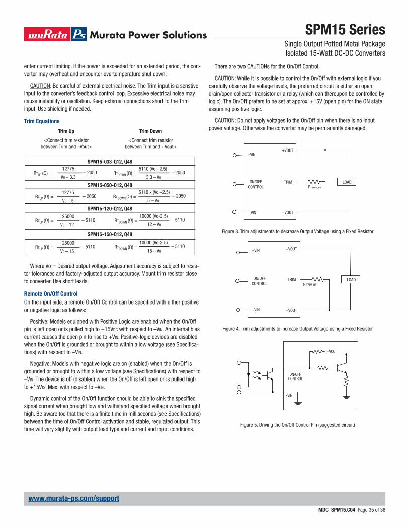
SPM15 SeriesSingle Output Potted Metal Package Isolated 15-Watt DC-DC Converters
MDC_SPM15.C04 Page 35 of 36
www.murata-ps.com/support
enter current limiting. If the power is exceeded for an extended period, the con-verter may overheat and encounter overtemperature shut down.
CAUTION: Be careful of external electrical noise. The Trim input is a senstive input to the converter’s feedback control loop. Excessive electrical noise may cause instability or oscillation. Keep external connections short to the Trim input. Use shielding if needed.
Trim Equations
Trim Up Trim Down
<Connect trim resistor between Trim and –Vout>
<Connect trim resistor between Trim and +Vout>
Where Vo = Desired output voltage. Adjustment accuracy is subject to resis-tor tolerances and factory-adjusted output accuracy. Mount trim resistor close to converter. Use short leads.
Remote On/Off Control
On the input side, a remote On/Off Control can be specifi ed with either positive or negative logic as follows:
Positive: Models equipped with Positive Logic are enabled when the On/Off pin is left open or is pulled high to +15VDC with respect to –VIN. An internal bias current causes the open pin to rise to +VIN. Positive-logic devices are disabled when the On/Off is grounded or brought to within a low voltage (see Specifi ca-tions) with respect to –VIN.
Negative: Models with negative logic are on (enabled) when the On/Off is grounded or brought to within a low voltage (see Specifi cations) with respect to –VIN. The device is off (disabled) when the On/Off is left open or is pulled high to +15VDC Max. with respect to –VIN.
Dynamic control of the On/Off function should be able to sink the specifi ed signal current when brought low and withstand specifi ed voltage when brought high. Be aware too that there is a fi nite time in milliseconds (see Specifi cations) between the time of On/Off Control activation and stable, regulated output. This time will vary slightly with output load type and current and input conditions.
There are two CAUTIONs for the On/Off Control:
CAUTION: While it is possible to control the On/Off with external logic if you carefully observe the voltage levels, the preferred circuit is either an open drain/open collector transistor or a relay (which can thereupon be controlled by logic). The On/Off prefers to be set at approx. +15V (open pin) for the ON state, assuming positive logic.
CAUTION: Do not apply voltages to the On/Off pin when there is no input power voltage. Otherwise the converter may be permanently damaged.
Figure 3. Trim adjustments to decrease Output Voltage using a Fixed Resistor
LOADRTRIM DOWN
+VOUT
TRIM ON/OFFCONTROL
−VIN −VOUT
+VIN
SPM15-120-Q12, Q48
SPM15-050-Q12, Q48
– 2050VO – 5
12775– 2050
5 – VO
5110 x (Vo –2.5)RTUP (Ω) = RTDOWN (Ω) =
VO – 12– 5110
25000– 5110
12 – VO
10000 (Vo-2.5)RTUP (Ω) = RTDOWN (Ω) =
SPM15-150-Q12, Q48
VO – 15– 5110
25000– 5110
15 – VO
10000 (Vo-2.5)RTUP (Ω) = RTDOWN (Ω) =
VO – 3.3– 2050
12775RTDOWN (Ω) =RTUP (Ω) = – 2050
3.3 – VO
5110 (Vo - 2.5)SPM15-033-Q12, Q48
Figure 4. Trim adjustments to increase Output Voltage using a Fixed Resistor
+VOUT
TRIM ON/OFFCONTROL
−VIN
LOADR TRIM UP
−VOUT
+VIN
Figure 5. Driving the On/Off Control Pin (suggested circuit)
ON/OFFCONTROL
-VIN
+VCC
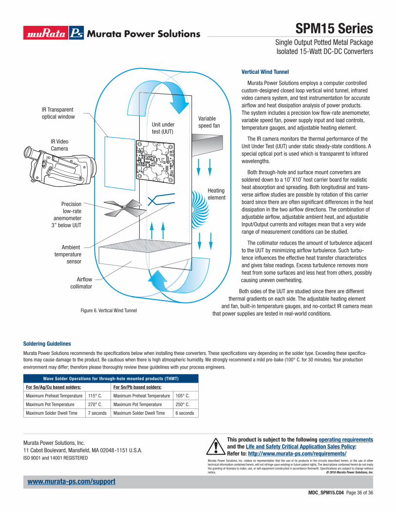
SPM15 SeriesSingle Output Potted Metal PackageIsolated 15-Watt DC-DC Converters
MDC_SPM15.C04 Page 36 of 36
www.murata-ps.com/support
Murata Power Solutions, Inc. makes no representation that the use of its products in the circuits described herein, or the use of other technical information contained herein, will not infringe upon existing or future patent rights. The descriptions contained herein do not imply the granting of licenses to make, use, or sell equipment constructed in accordance therewith. Specifi cations are subject to change without notice. © 2016 Murata Power Solutions, Inc.
Murata Power Solutions, Inc. 11 Cabot Boulevard, Mansfi eld, MA 02048-1151 U.S.A.ISO 9001 and 14001 REGISTERED
This product is subject to the following operating requirements
and the Life and Safety Critical Application Sales Policy:
Refer to: http://www.murata-ps.com/requirements/
Soldering Guidelines
Murata Power Solutions recommends the specifi cations below when installing these converters. These specifi cations vary depending on the solder type. Exceeding these specifi ca-tions may cause damage to the product. Be cautious when there is high atmospheric humidity. We strongly recommend a mild pre-bake (100° C. for 30 minutes). Your production
environment may differ; therefore please thoroughly review these guidelines with your process engineers.
Wave Solder Operations for through-hole mounted products (THMT)
For Sn/Ag/Cu based solders: For Sn/Pb based solders:
Maximum Preheat Temperature 115° C. Maximum Preheat Temperature 105° C.
Maximum Pot Temperature 270° C. Maximum Pot Temperature 250° C.
Maximum Solder Dwell Time 7 seconds Maximum Solder Dwell Time 6 seconds
Figure 6. Vertical Wind Tunnel
IR Video Camera
IR Transparentoptical window Variable
speed fan
Heating element
Ambient temperature
sensor
Airflowcollimator
Precisionlow-rate
anemometer3” below UUT
Unit undertest (UUT)
Vertical Wind Tunnel
Murata Power Solutions employs a computer controlled custom-designed closed loop vertical wind tunnel, infrared video camera system, and test instrumentation for accurate airfl ow and heat dissipation analysis of power products. The system includes a precision low fl ow-rate anemometer, variable speed fan, power supply input and load controls, temperature gauges, and adjustable heating element.
The IR camera monitors the thermal performance of the Unit Under Test (UUT) under static steady-state conditions. A special optical port is used which is transparent to infrared wavelengths.
Both through-hole and surface mount converters are soldered down to a 10˝ X10˝ host carrier board for realistic heat absorption and spreading. Both longitudinal and trans-verse airfl ow studies are possible by rotation of this carrier board since there are often signifi cant differences in the heat dissipation in the two airfl ow directions. The combination of adjustable airfl ow, adjustable ambient heat, and adjustable Input/Output currents and voltages mean that a very wide range of measurement conditions can be studied.
The collimator reduces the amount of turbulence adjacent to the UUT by minimizing airfl ow turbulence. Such turbu-lence infl uences the effective heat transfer characteristics and gives false readings. Excess turbulence removes more heat from some surfaces and less heat from others, possibly causing uneven overheating.
Both sides of the UUT are studied since there are different thermal gradients on each side. The adjustable heating element
and fan, built-in temperature gauges, and no-contact IR camera mean that power supplies are tested in real-world conditions.