Embed Size (px)
Citation preview

Split Rotor Concept for Permanent Magnet Electrical Machines
Mehmet C. Kulan
Newcastle University School of Engineering, NE1 7RU
Newcastle Upon Tyne, UK [email protected]
Nick J. Baker
Newcastle University School of Engineering, NE1 7RU
Newcastle Upon Tyne, UK [email protected]
Simon Turvey
Rolls – Royce Plc, UK The Derwent Building
5000 Solihull Parkway, B37 7YP [email protected]
Abstract — This paper discusses a field weakening method for permanent magnet electrical machines. The proposed method can be an alternative to complex mechanical field weakening methods for safety critical applications. The developed concept is based on a split rotor in which a permanent magnet rotor is split into two parts to achieve two states of field excitation; either maximum flux output or the least flux output, depending on alignments between the rotor parts, having a degree of freedom to rotate on the shaft. The stator of the permanent magnet (PM) machine exposes two magnetic fluxes by the split rotor sections. Thus, the fixed nature of the PM excitation can be altered by this concept to achieve a wide speed range, which is a key concern in PM electrical machines at higher speeds. A number of 3D finite element (FE) simulations and a Simulink/Matlab model have been implemented to investigate the dynamic behavior of the system. Although it is challenging to computationally investigate the behavior of the split rotor at different operating conditions due to complex torque interactions, altering the relative angular position of the free-to-rotate rotor on a shaft, the proposed method might eliminate the complex implementation of mechanical field weakening apparatus for PM electrical machines. Thus, a PM machine with split rotor would be used over a wide speed range without excessive voltages at high speeds in fault tolerant aerospace applications.
Keywords — Aerospace, Permanent Magnet Machine, Fault Tolerant PM Machine, Field Weakening, Mechanical Field Weakening, Split Rotor
I. INTRODUCTION
Permanent magnet (PM) synchronous electric machines have several advantages including high power density, high efficiency and reliability over traditional electrical machines such as induction machines, wound field motors/generators. In safety-critical applications, PM machines are designed specially to improve its fault tolerance yet the key concern in PM machines is that the source of excitation driving the fault current cannot be shut down due to a fixed excitation of the rotor magnets [1].
The principal issue in the operation of PM electric machines is that the performance of the PM machine at lower speeds cannot be achieved at higher speeds due to the fact that flux delivered by the permanent magnets is a function of rotor speed. This means that the voltage of a PM machine at high speeds is greater than can be accommodated. If PM machines are required for the applications over a wide speed range, the source of excitation due to permanent magnets is required to be disturbed in such a way that the net magnetic flux would be altered to limit the machine voltage over a wide speed range.
Excessive voltages at high speeds are the fundamental problem in permanent magnet machines and many schemes have been proposed to limit the output voltage in the literature [2, 3]. Active field weakening control methods, mechanical field weakening and per-unit (i.e. rated current with reactance limitation) designs are alternatives to overcome limited voltages at high operating speeds [4]. Active control methods for field weakening and per-unit designs to limit the short circuit current at high speeds are common methods in safety critical applications such as aerospace alternators but the regulator/drive systems apply excessive voltages to the load under these schemes, which is certainly not desired.
Complex mechanical systems for field weakening (i.e. mechanical field weakening apparatus) are relatively straightforward in theory but not easy to implement in practice due to their dead weight under lower/normal speeds, mechanical complexity and reliability [1]. Therefore, in this paper, an alternative method to mechanical field weakening methods has been discussed to demonstrate that mechanical field weakening methods, previously reported in the literature [5-8] could be replaced by a much simpler mechanical solution without utilizing external apparatus. The concept is based on a split rotor where a permanent magnet rotor is split into two elements (large and small sections) to manipulate the magnetic flux output of the rotor, dependent upon permanent magnet positions at different operating conditions of an electrical machine.
II. SPLIT ROTOR CONCEPT – FINITE ELEMENT MODELLING
Split rotor concept has been simulated in 3D FE modeland each principal component (i.e. large rotor, small rotor and stator) is isolated from the other components. (Fig. 1.)
Fig.1. Boundary regions for split rotor 3D FE Model
Air boundary regions are crucial as this allows the user to separate large rotor part, small rotor part and stator from each other. This implies FE model creates three different torque components. It can be also noted that there are two air-gaps in the model; first one is radial machine airgap and second one is axial airgap between the large and small rotor sections.
*** NCL eprint version***
Published in: 2019 IEEE International Electric Machines & Drives Conference (IEMDC) Date of Conference: 12-15 May 2019 Date Added to IEEE Xplore: 05 August 2019 ISBN Information: DOI: 10.1109/IEMDC.2019.8785239
Inaccurate setup of the boundary regions will not allow the user to run the model in 3D FEA with perfectly isolated torque elements.
The direction of permanent magnets in 3D model is radially inwards/outwards as usual. Therefore, the interaction between the rotors will not be significant as the rotor parts experience only axial interaction along the shaft. However, the magnetic torque interaction between the rotor parts is a crucial parameter to get the rotors aligned/unaligned, depending on overall torque interactions on the system.
A. Working Principle of a Fault Tolerant Alternator with aSplit Rotor
A fault tolerant alternator with a split rotor must satisfy anumber of criterions in order to achieve a field weakening at higher speeds without the use of an external field weakening instruments such as mechanical actuators. They are given as follows: o With the main segment (i.e. large rotor section) of the
rotor driven by the shaft and the smaller section in itsdefault state (N-S alignment) with the large rotorsection, on no load condition the magnetic torqueinteraction between the rotor segments will keep therotor elements in N-S state.
o If the rotor segments are initially in N-S state and amaximum phase current is applied to the stator, it needsto be demonstrated that the torque on the smaller rotorsection due to armature reaction is greater than thetorque created by N-S magnetic interaction between therotor sections. This implies that the small rotor sectionwould be dragged out the alignment. Thus, it helpsimprove the machine output voltage during a normaloperation.
o If the smaller rotor section were aligned at some fixedposition (e.g. 90° electrical) and the machine was shortcircuited, there would be a resultant torque on the smallrotor section. It is required to show that the torque onthe smaller rotor section due to short circuit current isless than the magnetic torque interaction between therotor sections. Thus, the alternator could be shortcircuited upon detection of a fault that would get thewinding current reduced and makes the machine safe athigh operating speeds.
The given criterions above require in depth investigation of the split rotor whilst the machine is on no load, on load and at short circuit. However, this paper principally focuses on computational analysis of a fault tolerant permanent magnet alternator (PMA), previously reported in [9], in open circuit and on load conditions. Several scenarios have been implemented in 3D FE model of the split rotor concept to understand the important parameters of an alternator design with a split rotor.
B. Permanent Magnets Interaction in Split Rotor
Since the split rotor consists of two rotor parts where thelarge rotor part is fixed to the shaft and the small rotor part has a degree of freedom on the shaft (free-to-rotate one magnet pitch) as explained in Fig. 1, the magnetic torque interaction between the rotor parts axially positioned needs to be understood by performing 3D FE simulations. The interaction torque can be described with the magnet positions as given in Fig. 2.
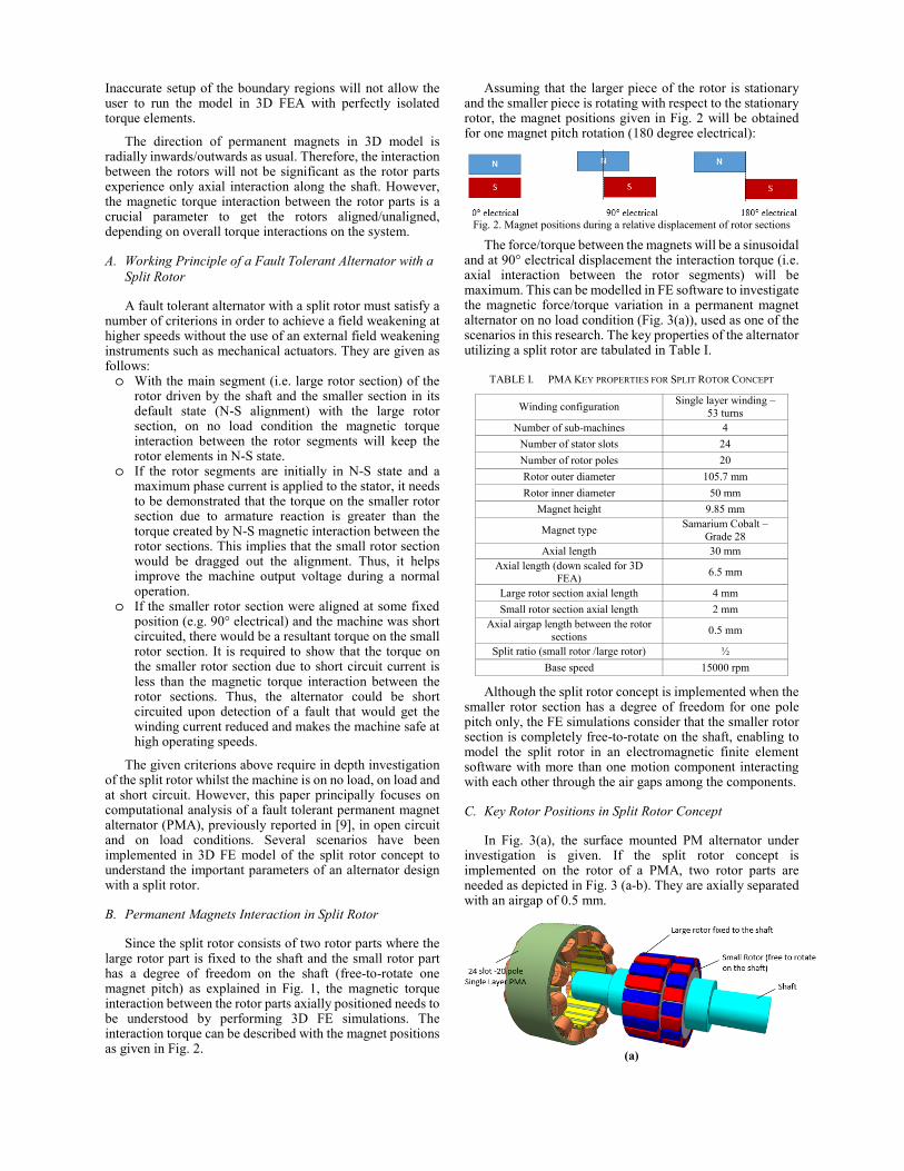
Assuming that the larger piece of the rotor is stationary and the smaller piece is rotating with respect to the stationary rotor, the magnet positions given in Fig. 2 will be obtained for one magnet pitch rotation (180 degree electrical):
Fig. 2. Magnet positions during a relative displacement of rotor sections
The force/torque between the magnets will be a sinusoidal and at 90° electrical displacement the interaction torque (i.e. axial interaction between the rotor segments) will be maximum. This can be modelled in FE software to investigate the magnetic force/torque variation in a permanent magnet alternator on no load condition (Fig. 3(a)), used as one of the scenarios in this research. The key properties of the alternator utilizing a split rotor are tabulated in Table I.
TABLE I. PMA KEY PROPERTIES FOR SPLIT ROTOR CONCEPT
Winding configuration Single layer winding –
53 turns Number of sub-machines 4
Number of stator slots 24
Number of rotor poles 20
Rotor outer diameter 105.7 mm
Rotor inner diameter 50 mm
Magnet height 9.85 mm
Magnet type Samarium Cobalt –
Grade 28 Axial length 30 mm
Axial length (down scaled for 3D FEA)
6.5 mm
Large rotor section axial length 4 mm
Small rotor section axial length 2 mm Axial airgap length between the rotor
sections 0.5 mm
Split ratio (small rotor /large rotor) ½
Base speed 15000 rpm
Although the split rotor concept is implemented when the smaller rotor section has a degree of freedom for one pole pitch only, the FE simulations consider that the smaller rotor section is completely free-to-rotate on the shaft, enabling to model the split rotor in an electromagnetic finite element software with more than one motion component interacting with each other through the air gaps among the components.
C. Key Rotor Positions in Split Rotor Concept
In Fig. 3(a), the surface mounted PM alternator underinvestigation is given. If the split rotor concept is implemented on the rotor of a PMA, two rotor parts are needed as depicted in Fig. 3 (a-b). They are axially separated with an airgap of 0.5 mm.
(a)

(b)
Fig. 3. Permanent magnet alternator (a) 24 slot -20 pole fault tolerant PMA, (b) 3D Split rotor of the PMA-without stator
There are two key positions in the split rotor as given in Fig. 4. These position can be obtained at different operating conditions. If the magnets are dragged into their natural position due to the interaction torque, the rotor will achieve the lowest output state in terms of magnetic flux. The magnitude of interaction torque between the rotor parts is dependent upon split ratio, rotor axial length, machine airgap length, axial airgap distance, as depicted in Fig. 4.
(a)
(b) Fig. 4. Split rotor: (a) Least output state (natural position); (b) Most output
state (aligned)
D. Achieving Field Weakening via Pre-Defined RotorPositions in 3D FE Model
The 3D FE investigation here aims to investigate thetorque variation between the rotor elements when the aligned small and large rotors rotate initially at the same speed and the small rotor is forced to rotate slower to achieve a natural position in the rotor elements. It is worth mentioning that the small rotor element is not free to rotate in this case. They obey pre-defined time-position functions as given in Fig. 5. It is also clear that the speed of small rotor element in Fig. 5(b) is changed in a step yet this is not possible in reality when the small rotor element is rotating freely on the shaft with air friction and rotational inertia.
(a)
(b) Fig 5. (a) Rotor position vs time – constrained; (b) Speed vs time
In Fig. 5, the initial speed of the rotor elements are 15000 rpm (90000 deg/s) and they start running when the magnets are in the most output state as illustrated in Fig. 4 (b). At t=0.4 ms, the small rotor section is constrained such that it drags the rotor section into natural position as given in Fig. 4 (a).
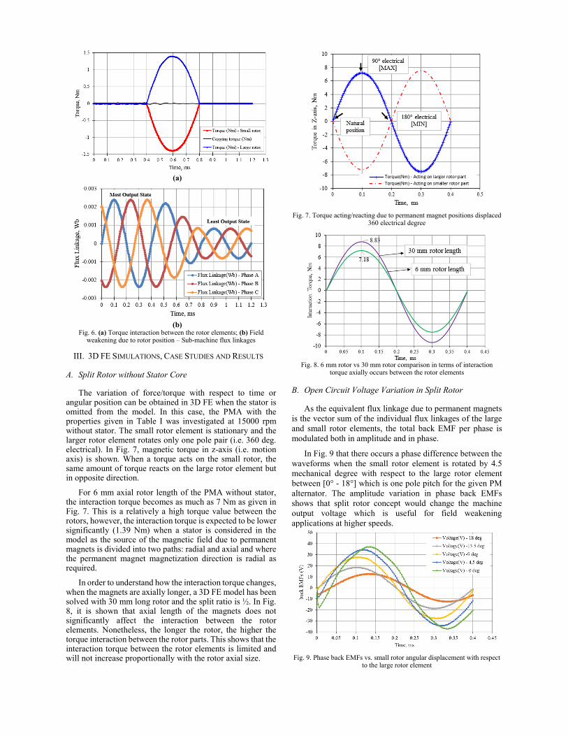
As shown in Fig. 6, the peak interaction torque between the magnets is 1.39 Nm. This occurs when there is no current in the stator windings (i.e. open circuit). The position change (180 degree electrical) in the small rotor forms a machine with lower magnetic loading since the equivalent magnetic field of the rotor will be minimum as the opposite magnets in the rotor elements are at N-S state.
Furthermore, the cogging torque in Fig. 6(a) oscillates around zero as expected and is independent of magnetic interaction between the rotor sections. This is an important result as the machine on load would generate two independent torque parameters (i.e. electromagnetic and magnets interaction torques) simultaneously and they would superpose on the rotor sections to give a net resultant torque.
(a)
(b)Fig. 6. (a) Torque interaction between the rotor elements; (b) Field
weakening due to rotor position – Sub-machine flux linkages
III. 3D FE SIMULATIONS, CASE STUDIES AND RESULTS
A. Split Rotor without Stator Core
The variation of force/torque with respect to time orangular position can be obtained in 3D FE when the stator is omitted from the model. In this case, the PMA with the properties given in Table I was investigated at 15000 rpm without stator. The small rotor element is stationary and the larger rotor element rotates only one pole pair (i.e. 360 deg. electrical). In Fig. 7, magnetic torque in z-axis (i.e. motion axis) is shown. When a torque acts on the small rotor, the same amount of torque reacts on the large rotor element but in opposite direction.
For 6 mm axial rotor length of the PMA without stator, the interaction torque becomes as much as 7 Nm as given in Fig. 7. This is a relatively a high torque value between the rotors, however, the interaction torque is expected to be lower significantly (1.39 Nm) when a stator is considered in the model as the source of the magnetic field due to permanent magnets is divided into two paths: radial and axial and where the permanent magnet magnetization direction is radial as required.
In order to understand how the interaction torque changes, when the magnets are axially longer, a 3D FE model has been solved with 30 mm long rotor and the split ratio is ½. In Fig. 8, it is shown that axial length of the magnets does not significantly affect the interaction between the rotor elements. Nonetheless, the longer the rotor, the higher the torque interaction between the rotor parts. This shows that the interaction torque between the rotor elements is limited and will not increase proportionally with the rotor axial size.
Fig. 7. Torque acting/reacting due to permanent magnet positions displaced 360 electrical degree
Fig. 8. 6 mm rotor vs 30 mm rotor comparison in terms of interaction torque axially occurs between the rotor elements
B. Open Circuit Voltage Variation in Split Rotor
As the equivalent flux linkage due to permanent magnetsis the vector sum of the individual flux linkages of the large and small rotor elements, the total back EMF per phase is modulated both in amplitude and in phase.
In Fig. 9 that there occurs a phase difference between the waveforms when the small rotor element is rotated by 4.5 mechanical degree with respect to the large rotor element between [0° - 18°] which is one pole pitch for the given PM alternator. The amplitude variation in phase back EMFs shows that split rotor concept would change the machine output voltage which is useful for field weakening applications at higher speeds.
Fig. 9. Phase back EMFs vs. small rotor angular displacement with respect to the large rotor element

IV. OPEN CIRCUIT PMA WITH SPLIT ROTOR
A. FE Simulation Setup and Important Parameters
In an open circuit machine, the only interaction betweenthe rotor and stator in terms of torque is cogging torque. However, in the split rotor concept, the rotor elements experience another torque on no load: interaction torque. Any random initial state (i.e. position) of the small rotor element, which is free to rotate on the shaft will create a torque interaction between the rotor parts. This torque interaction will drag the small rotor element into the natural position after a certain time, dependent on the speed of the shaft on no load condition. The small rotor element will not reach the natural position in a single time instant as the rotational displacement of the free rotor element is dependent on a number of motor parameters such as rotor mass, moment of inertia, viscous friction coefficient (i.e. damping constant) etc.
(a)
(b) Fig. 10. PMA on no load with split rotor where small rotor element is not at default state (i.e. initially 90° electrical shift between the rotor sections), (a)
3-D view of the PMA with split rotor, (b) 2-D view of the PMA
In Fig. 10(a), the machine is open circuit and the rotor magnets are initially not in their natural position. The large rotor element has a fixed speed on the shaft, 15000 rpm (i.e. 90000 deg/s) and the small rotor element is free to rotate with an initial speed of 15000 rpm. The anticipated physical phenomena here is that the small rotor element will catch the large rotor after a certain time. Nevertheless, the small element will not lock the large rotor just after 9 degree (i.e. half pole pitch) mechanical rotation since its inertia due to its speed will not allow the small rotor to come to a natural position in a step. Therefore, the small rotor will continue to rotate freely during a transient. After certain time, the small rotor element will lose its acceleration relative to the large rotor part and its position gets closer to large rotor part and finally the small rotor element will lock itself into the natural
position (i.e. N-S state). The simulation properties are summarised in Table II.
TABLE II. 3D FE ANALYSIS - SPLIT ROTOR ON NO LOAD
Fault tolerant alternator 24 slot – 20 pole, single
layer winding PMA
Number of motion components 2
Large rotor moment of inertia 0.032 .
Small rotor moment of inertia
. . (Artificially reduced by 1000 times to see more cycles in 3D FE model)
Initial speed of the large rotor section 90000 deg/s (15000 rpm)
Initial speed of the small rotor section 90000 deg/s
Large rotor speed control Constant speed
Small rotor speed control Free to rotate at any speed
Current in the stator phase windings 0 (i.e. open circuit)
Simulation end time 18 ms
Initial relative position of the smaller rotor section
9° mechanical (half magnet pitch)
B. 3D FE Simulation Results – Initial N-S State on No load
If the rotor sections are aligned in N-S state (i.e. naturalposition) when the smaller rotor element is free-to-rotate with respect to the larger rotor element, it must be demonstrated that the small rotor element rotates at the same speed as the large rotor without slipping on the shaft. This is shown in angular position and back EMF plots in Fig. 11 (a) and (b).
(a)
(b) Fig. 11. Split Rotor in the least output state, (a) Speed oscillation in small
rotor element, (b) back EMF at the least output state

In Fig. 11 (a), there is 1.5 deg/s (i.e. 0.25 rpm) peak oscillation (decays in time) on the small rotor element which can be ignored as the back EMF waveforms in Fig. 11(b) indicate that the free-to-rotate rotor element locks the large rotor element at 15000 rpm without changing its angular position. Thus, magnet to magnet interactions in axial airgap results in the least output state on no load condition.
C. 3D FE Simulation Results – Initial Random Position onNo load
In Fig. 12 (a), (b) and (c), open circuit 3D FE results aregiven. Steady state could not be achieved due to inertia of the free-to-rotate rotor section. In Fig. 12(a), the torque waveform decays in time to achieve zero torque at steady state. Conservation of energy applies here as the interaction torque decays due to core and magnet losses on no load condition. Similarly, speed waveform of the smaller rotor element oscillates around 15000 rpm and at steady state it is expected to achieve constant speed: 15000 rpm, after a transient.
(a)
(b)
(c)
Fig. 12. Split Rotor 3D FE analysis results on no load: (a) rotor sections interaction torque, (b) angular speed, (c) angular position
Reaching a constant speed for the smaller rotor section is an important result as it implies that any randomly chosen relative position of the small rotor element will lead to a natural position after certain transient time on no load condition. In other words, split rotor achieves N-S state when there is no current applied in the stator windings. Thus, open circuit criterion of the split rotor has been satisfied.
These 3D FE simulations takes about 200 hours with 6 physical core, 64 GB memory PC as the time constant of the system is mechanical rather than electrical. Therefore, a Simulink model would be required for the small rotor (i.e. free-to-rotate rotor) section to see the full mechanical response.
D. 3D FE Simulation Results – Initial Random Positionwith High Moment of Inertia on Small Rotor Section
The variation of back EMF waveforms is shown in Fig.13 when the moment of inertia of the rotor sections is kept in its original value as opposed to the given value in Table II. In this case, the interaction in the rotor sections occurs more slowly and visible. Thus, the field weakening could be realized clearly at the position when the free-to-rotate rotor element has 9° mechanical angle shift with respect to the large rotor element.
Fig. 13. The least and most output state of the split rotor on no load
In Fig. 13, the split rotor provides a peak back EMF of 37 V at the most output state and the least output back EMF gives a peak of 13 V. In this case, the field can be reduced almost one third while the split ratio is ½. It should be noted that the back EMF variations given in Fig. 13 are due to transients in the rotor positions. It does not imply steady state back EMF results.

V. MATLAB/SIMULINK MODEL OF THE SMALL ROTOR
ELEMENT
Since the waveforms given in Figure 12 and 13 does not achieve a steady state due to computational costs of 3D FE model with refined mesh, the torque and speed waveforms achieving a steady state were estimated using the given system equation in a differential form: 0 (1)
where and stand for electromagnetic and load toques respectively. and are moment of inertia and viscous friction constant, respectively. The boundary condition is the initial angular speed (rad/s) of the rotor element. The system equation can be solved in Simulink when there is no load torque in the system, as given in Fig. 14.
Fig. 14. Small Rotor Element Dynamic Model in Matlab/Simulink
In Fig. 14, the idealised net torque is predicted based on 3D FE model with a decay constant, 3 since the resultant torque on the small rotor element decays in time with a mechanical time constant dependent upon the system losses. The function of torque on the free-to-rotate rotor is in the form:
sin 2 (2)
where is peak torque, is decay constant as a function of time, is the phase of the waveform and is frequency modulation as a function of time as the 3D FE transient results show that torque waveform is far from ideal sine wave with a constant decay. Nonetheless, torque can be still reconstructed in Simulink with a pure sine wave, giving a similar torque and speed responses as shown in Fig. 15.
(a)
(b)
Fig. 15. Torque (a) and speed (b) variation on free-to-rotate rotor section on no load
VI. PMA WITH SPLIT ROTOR ON LOAD
So far it has been demonstrated that the split rotor concept achieves natural position (i.e. N-S alignment) on no load condition. Secondly, a current can be injected to the stator windings to investigate the influence of phase currents on the resultant torque of the free-to-rotate element. The desired response here is that the electromagnetic torque due to phase currents moves the small rotor section into the most output state where it is in the least output state at start.
Fig. 16. Net torque on the free-to-rotate rotor element on load condition

A 3D FE simulation was investigated at which phase currents are 240 and the initial rotor position is the least output state (i.e. natural position). The phase currents applied are close to the value at which the torque constant, saturates for the given machine (PMA).
In Fig. 16, it should be noted that the net torque due to phase currents and interaction between the rotor sections oscillates with a peak of 2.8 Nm and it decays in time. It is expected that the net torque at steady state will not be zero as there is an offset in the waveform. Any torque due tothe stator currents higher than the holding torque/force value between the rotor elements drags the small rotor elements towards the most output state and so the resultant PM flux linkage in the phase windings increases. Thus, the split rotor could achieve the most output state when the phase currents are high enough.
Furthermore, the short circuit current is another scenario for the PMA with split rotor concept as explained in Section II A. This needs to be further investigated by the authors as it is crucial part of the concept to understand how an alternator with split rotor can be directed into a field weakening region upon detection of a fault, by shorting the phases at higher speeds. In this case, the anticipated phenomena is that the magnetic force between the rotor sections must be greater than the force due to armature current. Thus, the smaller rotor section could be dragged into the least output state, resulting lower magnetic flux linkage in the stator windings.
VII. CONCLUSION
In this paper, a split rotor for fault tolerant alternators has been introduced. A permanent magnet alternator for aerospace has been used as a case study to investigate the different scenarios of the split rotor concept. It is shown that a free-to-rotate rotor can achieve the least output state when there is no current in the stator windings. In addition, it is also shown that the free-to-rotate rotor section can be controlled by the phase currents to get the least or most output states at different operating conditions. Long transients are a problem in 3D FE simulations as they inhibit the steady state results in relatively short time periods. Also, the effect of important machine parameters such as rotor length and inertia etc. on the performance of split rotor has been presented. The authors need more detailed research outcomes to demonstrate that the concept introduced here is useful for flight critical fault tolerant applications such as aerospace alternators.
ACKNOWLEDGMENT
The work presented in this paper is based on a patent application by Rolls-Royce plc. The inventors are Simon Turvey and Keir Wilkie from Rolls-Royce and UTC, respectively. This work also forms a part of the ENCASE project, funded by the Aerospace Technology Institute, administered by Innovate UK under application 91851-263262. The authors and inventors declare that there is no conflict of interest regarding the publication of this article in IEEE conference proceedings.
REFERENCES
[1] C. J. Ifedi, "A high torque density, direct drive in-wheel motor for electric vehicles," Ph.D. Thesis, Newcastle University,2014.
[2] A. M. El-Refaie, "Fault-tolerant permanent magnet machines:a review," IET Electric Power Applications, vol. 5, pp. 59-74,2011.
[3] T. A. Lipo and M. Aydin, "Field weakening of permanentmagnet machines–design approaches," Proc. EPE-PEMC,Riga, Latvia, 2004.
[4] Simon Turvey, Keir Wilkie "Split Rotor for Permanent Magnet MAachines- A patent application report," Control DataServices, Rolls-Royce plc, UK, Report 2018.
[5] M. Masuzawa, N. Hirao, T. Sasaki, and M. Mita, "Brushlessmotor having permanent magnets," U.S. Patent No. 5,821,710. 13 Oct. 1998.
[6] L. P. Zepp and J. W. Medlin, "Brushless permanent magnetmotor or alternator with variable axial rotor/stator alignment to increase speed capability," U.S. Patent No. 6,555,941. 29 Apr. 2003.
[7] T.-H. S.-H. Yang, Town; Dzan-Hwa, "Electrical machine with structure for axially moving the rotor using centrifugal force," European Patent Application, EP 1 432 101 A1, 2004.
[8] K. A. Lovejoy, "Permanent magnet generator," U.S. Patent No. 8,823,331. 2 Sep. 2014.
[9] M. C. Kulan, N. J. Baker and S. Turvey, "Design and Analysis of a Fault Tolerant Permanent Magnet Alternator forAerospace," 2018 XIII International Conference on ElectricalMachines (ICEM), Alexandroupoli, 2018, pp. 622-9.