Embed Size (px)
Citation preview

Split Options for 5G Radio Access Networks
Paul Arnold, Nico Bayer, Jakob Belschner, Gerd Zimmermann
Technology InnovationDeutsche Telekom AG

IntroductionTwo splits envisioned in the 5G RAN
Control-Plane / User-Plane Split
“CU/DU”-Split (Central and Distributed Units)
Central and Distributed Units

Central and Distributed Units
› Centralization of parts of the processing in a central unit
› Motivation: Simplified implementation of interference coordination, multi-connectivity, traffic-steering, …
› Several options to split the protocol stack, each with different demand on the underlying interface (xHaul)
› Flexibility to implement centralization in different deployments
Split Options in the Protocol Stack

Examples for data rate requirements on the xHaul interface
0,0
2,0
4,0
6,0
8,0
10,0
12,0
8 7-1 7-3 6
xHau
l dat
a ra
te in
Gb
it/s
3GPP Split Option
2 antenna ports / 2 layers
4 antenna ports / 4 layers
8 antenna ports / 8 layers
0,1
1,0
10,0
100,0
1000,0
10000,0
8 7-1 7-3 6
xHau
l dat
a ra
te in
Gb
it/s
3GPP Split Option
LTE 20 MHz
5G AIV (< 6 GHz /100 MHz)5G AIV (> 6 GHz /400 MHz)
LTE Potential 5G Air Interfaces

Control-Plane / User-Plane Split

Control-Plane / User-Plane Split
› Categorize network functions into Control-Plane (CP) and User-Plane (UP) functions
› Define standardized interfaces for interaction between CP and UP
› Consistent control over network elements from different vendors
› Avoid replacement of UP in case CP is modified
› More flexible network
Pros
› Tight coupling of CP / UP Full separation might be complex
› Standardization for all interfaces is required
› Additional effort in terms of testing
Cons

Interactions between CP and UP
1: DL Buffer Status
2: Payload Selection
3: Payload Selection, DL Resource Assignment, UL Grants
4: Retransmission Control
5: Broadcast Channel Information
6: Coding Scheme
7: Antenna Mapping, Precoder, Modulation Scheme
8: Reference Symbols, Synchronization Channels
9: Antenna Weights
10: Channel State Information (from UL Sounding)
11: Channel State Information (CQI Reporting),
UL Scheduling Request
12: HARQ Status
Radio Unit (RU)
1
PD
CP
RLC
(asyn
ch.)
RLC
(syn
ch.)
MA
C H
igh (
MU
X)
MA
C L
ow
(H
AR
Q)
FE
C C
odin
g
Scra
mblin
g
Modula
tion
Laye
r M
appin
g
Dig
ital B
eam
form
ing Resource Element
Mapping & IFFT
Resource Element
Mapping & IFFT
D/A
Conversion
D/A
Conversion
Antenna
#1
Antenna
#N
2 3 4 6 7
RLC
(asyn
ch.)
RLC
(syn
ch.)
MA
C H
igh (
DeM
UX
)
MA
C L
ow
(H
AR
Q)
FE
C D
ecodin
g
Descra
mblin
g
Laye
r D
em
appin
g
Dem
odula
tion
Equaliz
ation
Resource Element
Demapping & FFT
Resource Element
Demapping & FFT
A/D
Conversion
A/D
Conversion
S1-U*
S1-U*
Downlink User
Plane
Uplink User
Plane
Control PlaneICIC
S1-C*
8
Cell
Config
5
10
Analo
gB
eam
form
ing
(RF
Pre
codin
g)
Antenna
#1
Antenna
#M
Analo
g
RF
Com
bin
ing
Short-Term Scheduler 9
1112
RRC
RU
Config
PD
CP
X2-C*
3GPP Split
Option
3 87-3654 7-12

Overall Network Architecture

Proposed Overall Network Architecture› Forwarding of data in the
transport network through based on SDN– Implements CP/UP split
› Central Access Controller (CAC) is the centralized network element in Radio Access Network– Separated into CP and UP part
› xHaul-Interface to the radio sites– Flexible adaptation depending
on the network deployment

Use Case: Multi-Connectivity
1
PD
CP
(incl. F
ast
Sw
itch o
r
Packet
Duplic
ation)
PHY
2
S1-U*
Downlink User Plane
Low
er
CP
AIV
1
S1-C*
8
Cell
Config
5
1012
RUMACRLC
PHY RUMACRLC
PHY RUMACRLC
PHY RUMACRLC
QoS
/ S
lice
Enfo
rcem
ent
AIV 2
AIV 1
AIV 1
AIV 2
Uplink User Plane
S1-U*
76
Short-Term Scheduler
11
43
QoS
/ S
lice
Contr
ol
RR
C
PD
CP
(incl. F
ast
Sw
itch o
r
Packet
Duplic
ation)
Multi-C
ell/
-AIV
Resourc
e
Mappin
g
Com
mon H
igher
CP L
ow
er
CP
AIV
2
Central Unit (CU) Distributed Unit (DU)
… … ………………………
› Multi-Connectivity is important in 5G, especially for:– mmWave Radio
– Ultra-Reliable Communication
› Figure shows potential implementation based on CU / DU split option 2
› Additional CP functions for:– Traffic Steering (Multi-Cell / Multi-
AIV Resource Mapping)
– Quality of Service
– Network Slicing
2

Summary and Conclusions
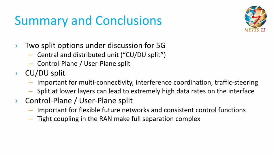
Summary and Conclusions
› Two split options under discussion for 5G– Central and distributed unit (“CU/DU split”)– Control-Plane / User-Plane split
› CU/DU split– Important for multi-connectivity, interference coordination, traffic-steering– Split at lower layers can lead to extremely high data rates on the interface
› Control-Plane / User-Plane split– Important for flexible future networks and consistent control functions– Tight coupling in the RAN make full separation complex

Thank Youhttps://metis-ii.5g-ppp.eu/