Embed Size (px)
Citation preview
1SPL_211 © 2001, Cisco Systems, Inc. All rights reserved.
3SPL_211 © 2001, Cisco Systems, Inc. All rights reserved.© 2001, Cisco Systems, Inc. All rights reserved.© 2001, Cisco Systems, Inc. All rights reserved.
Design Principles forDSL-Based Access Solutions
Thomas MartinSession SPL-211
© 2001, Cisco Systems, Inc. All rights reserved. 4© 2001, Cisco Systems, Inc. All rights reserved. 4© 2001, Cisco Systems, Inc. All rights reserved. 4SPL_211
• Digital Subscriber Line Technologies• Subscriber Connection Models• Reaching the Services• Case Studies• Summary, Question and Answer
Agenda
© 2001, Cisco Systems, Inc. All rights reserved. 5© 2001, Cisco Systems, Inc. All rights reserved. 5© 2001, Cisco Systems, Inc. All rights reserved. 5SPL_211
DSL“Modem”
Value-AddedPacket Network
End-User
DSL“Modem”
DSLDSL
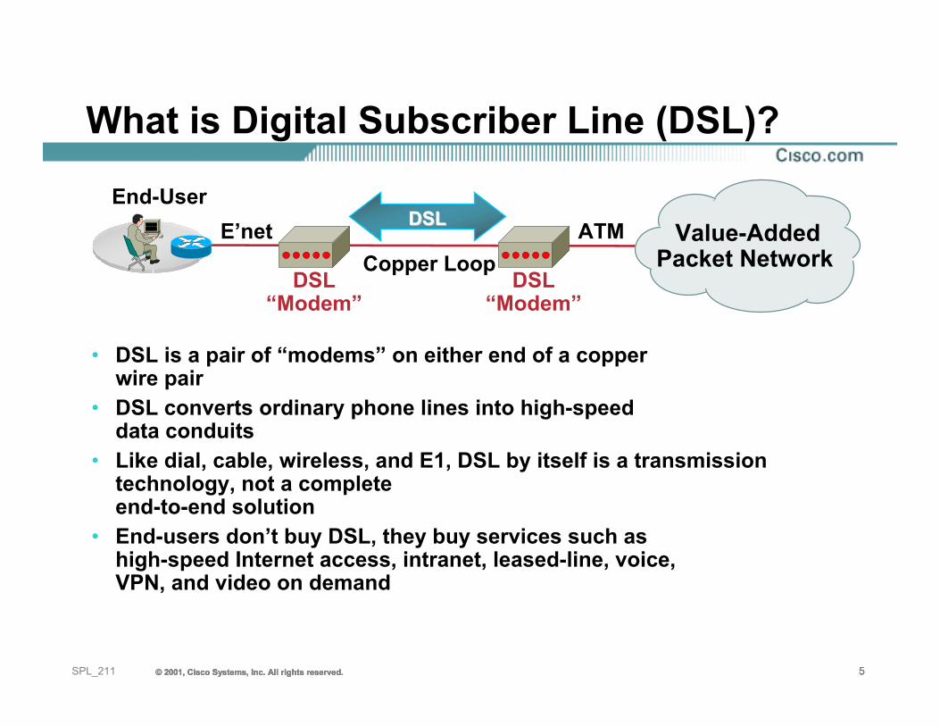
• DSL is a pair of “modems” on either end of a copper wire pair
• DSL converts ordinary phone lines into high-speed data conduits
• Like dial, cable, wireless, and E1, DSL by itself is a transmission technology, not a complete end-to-end solution
• End-users don’t buy DSL, they buy services such as high-speed Internet access, intranet, leased-line, voice, VPN, and video on demand
Copper LoopE’net ATM
What is Digital Subscriber Line (DSL)?
© 2001, Cisco Systems, Inc. All rights reserved. 6© 2001, Cisco Systems, Inc. All rights reserved. 6© 2001, Cisco Systems, Inc. All rights reserved. 6SPL_211
DSL Modem Technology
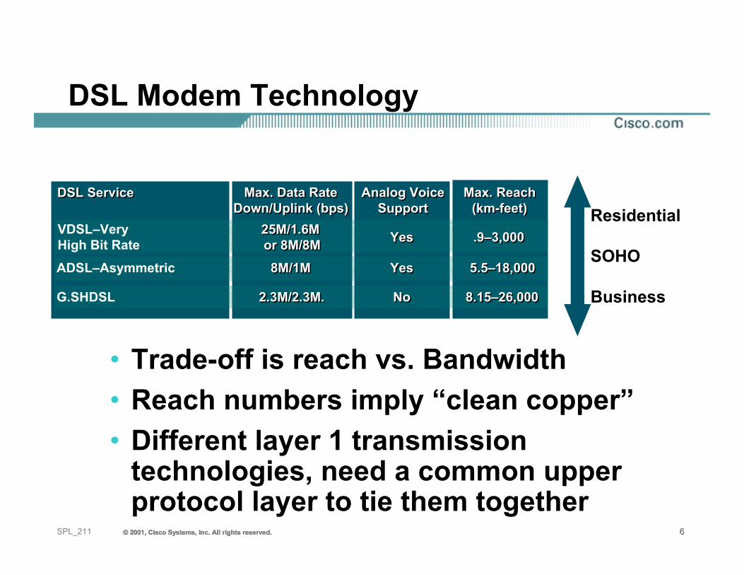
• Trade-off is reach vs. Bandwidth• Reach numbers imply “clean copper”• Different layer 1 transmission
technologies, need a common upper protocol layer to tie them together
Max. Data RateDown/Uplink (bps)
Max. Data RateDown/Uplink (bps)
VDSL–VeryHigh Bit Rate
25M/1.6M or 8M/8M25M/1.6M or 8M/8M
Analog VoiceSupport
Analog VoiceSupport
YesYes
Max. Reach(km-feet)
Max. Reach(km-feet)
.9–3,000.9–3,000
DSL ServiceDSL Service
ADSL–Asymmetric 8M/1M8M/1M YesYes 5.5–18,0005.5–18,000
G.SHDSL 2.3M/2.3M.2.3M/2.3M. NoNo 8.15–26,0008.15–26,000
Residential
SOHO
Business
© 2001, Cisco Systems, Inc. All rights reserved. 7© 2001, Cisco Systems, Inc. All rights reserved. 7© 2001, Cisco Systems, Inc. All rights reserved. 7SPL_211
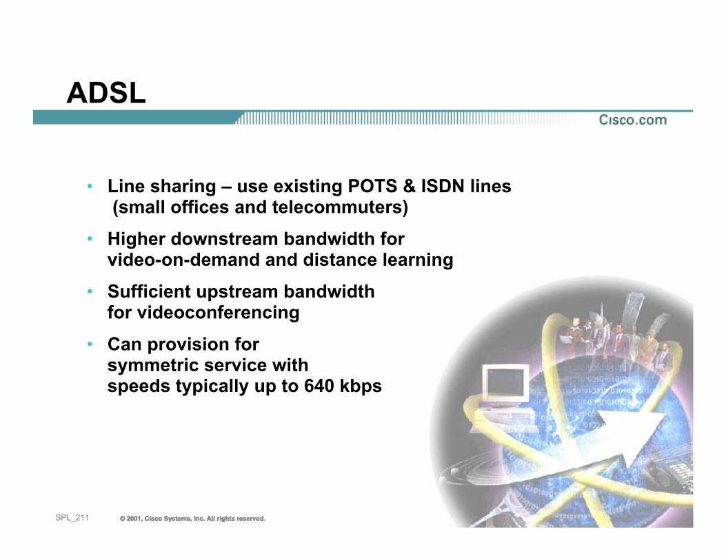
• Line sharing – use existing POTS & ISDN lines (small offices and telecommuters)
• Higher downstream bandwidth for video-on-demand and distance learning
• Sufficient upstream bandwidth for videoconferencing
• Can provision for symmetric service with speeds typically up to 640 kbps
ADSL
© 2001, Cisco Systems, Inc. All rights reserved. 8© 2001, Cisco Systems, Inc. All rights reserved. 8© 2001, Cisco Systems, Inc. All rights reserved. 8SPL_211
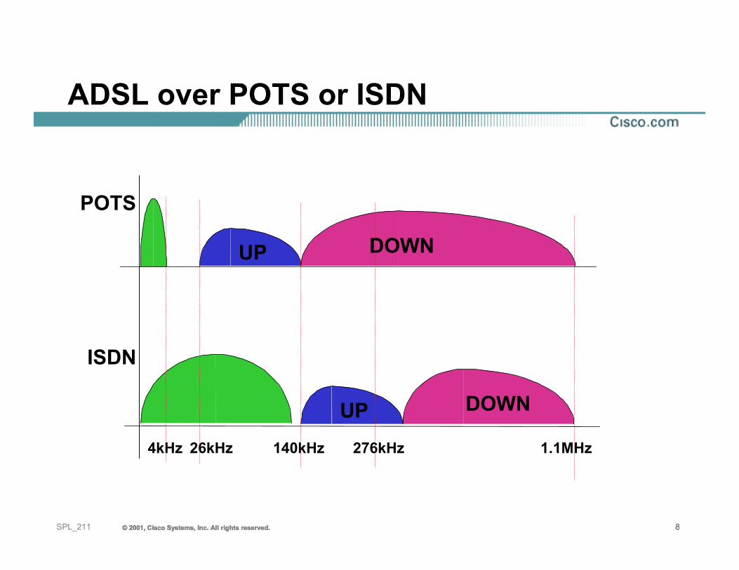
POTS
UP DOWN
26kHz
ISDN
DOWNUP140kHz 276kHz4kHz 1.1MHz
ADSL over POTS or ISDN
© 2001, Cisco Systems, Inc. All rights reserved. 9© 2001, Cisco Systems, Inc. All rights reserved. 9© 2001, Cisco Systems, Inc. All rights reserved. 9SPL_211
• ITU standard• Symmetrical service up to 2.3 mbps• Multirate (192kb/s - 2.3mbps) unlike HDSL• Spectrally friendly (TC-PAM) with ADSL• 30% longer reach than SDSL• Repeatable• More upstream bandwidth for bandwidth-
intensive applications• Affordable T1/E1 alternative
G.SHDSL
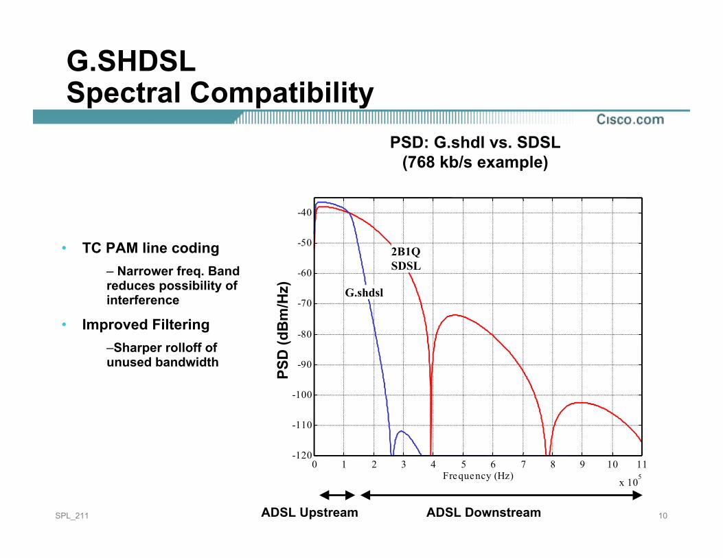
PSD: G.shdsl vs. SDSL(768 kb/s example)
0 1 2 3 4 5 6 7 8 9 10 11
x 105
-120
-110
-100
-90
-80
-70
-60
-50
-40
Frequency (Hz)
PS
D (d
Bm
/Hz)
G.shdsl
2B1QSDSL
ADSL Upstream ADSL Downstream
• TC PAM line coding– Narrower freq. Band reduces possibility of interference
• Improved Filtering–Sharper rolloff of unused bandwidth
G.SHDSLSpectral Compatibility
PSD: G.shdl vs. SDSL(768 kb/s example)
10SPL_211 ADSL DownstreamADSL Upstream
PSD
(dB
m/H
z)
© 2001, Cisco Systems, Inc. All rights reserved. 11© 2001, Cisco Systems, Inc. All rights reserved. 11© 2001, Cisco Systems, Inc. All rights reserved. 11SPL_211
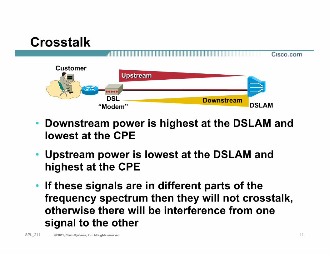
• Downstream power is highest at the DSLAM and lowest at the CPE
• Upstream power is lowest at the DSLAM and highest at the CPE
• If these signals are in different parts of the frequency spectrum then they will not crosstalk, otherwise there will be interference from one signal to the other
DSL“Modem”
Customer
DSLAM
UpstreamUpstream
Downstream
Crosstalk
© 2001, Cisco Systems, Inc. All rights reserved. 12© 2001, Cisco Systems, Inc. All rights reserved. 12© 2001, Cisco Systems, Inc. All rights reserved. 12SPL_211
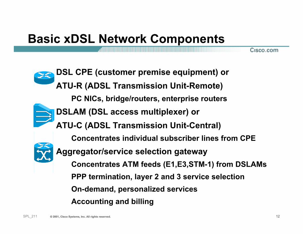
DSL CPE (customer premise equipment) orATU-R (ADSL Transmission Unit-Remote)
PC NICs, bridge/routers, enterprise routersDSLAM (DSL access multiplexer) orATU-C (ADSL Transmission Unit-Central)
Concentrates individual subscriber lines from CPEAggregator/service selection gateway
Concentrates ATM feeds (E1,E3,STM-1) from DSLAMsPPP termination, layer 2 and 3 service selectionOn-demand, personalized servicesAccounting and billing
Basic xDSL Network Components
© 2001, Cisco Systems, Inc. All rights reserved. 13© 2001, Cisco Systems, Inc. All rights reserved. 13© 2001, Cisco Systems, Inc. All rights reserved. 13SPL_211
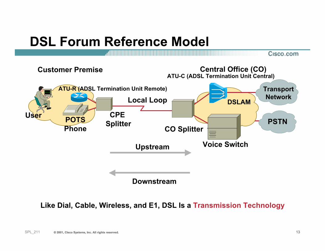
DSL Forum Reference Model
Central Office (CO)
PSTN
Customer Premise
DSLAM
Voice Switch
User
ATU-R (ADSL Termination Unit Remote)
POTSPhone
ATU-C (ADSL Termination Unit Central)
Local Loop
CO Splitter
CPESplitter
Upstream
Downstream
Like Dial, Cable, Wireless, and E1, DSL Is a Transmission Technology
TransportNetwork
© 2001, Cisco Systems, Inc. All rights reserved. 14© 2001, Cisco Systems, Inc. All rights reserved. 14© 2001, Cisco Systems, Inc. All rights reserved. 14SPL_211
• Reach and quality of copper• Power dissipation • Signal to noise ratio• Error correction algorithms• Loop testing
Layer One Considerations
© 2001, Cisco Systems, Inc. All rights reserved. 15© 2001, Cisco Systems, Inc. All rights reserved. 15© 2001, Cisco Systems, Inc. All rights reserved. 15SPL_211
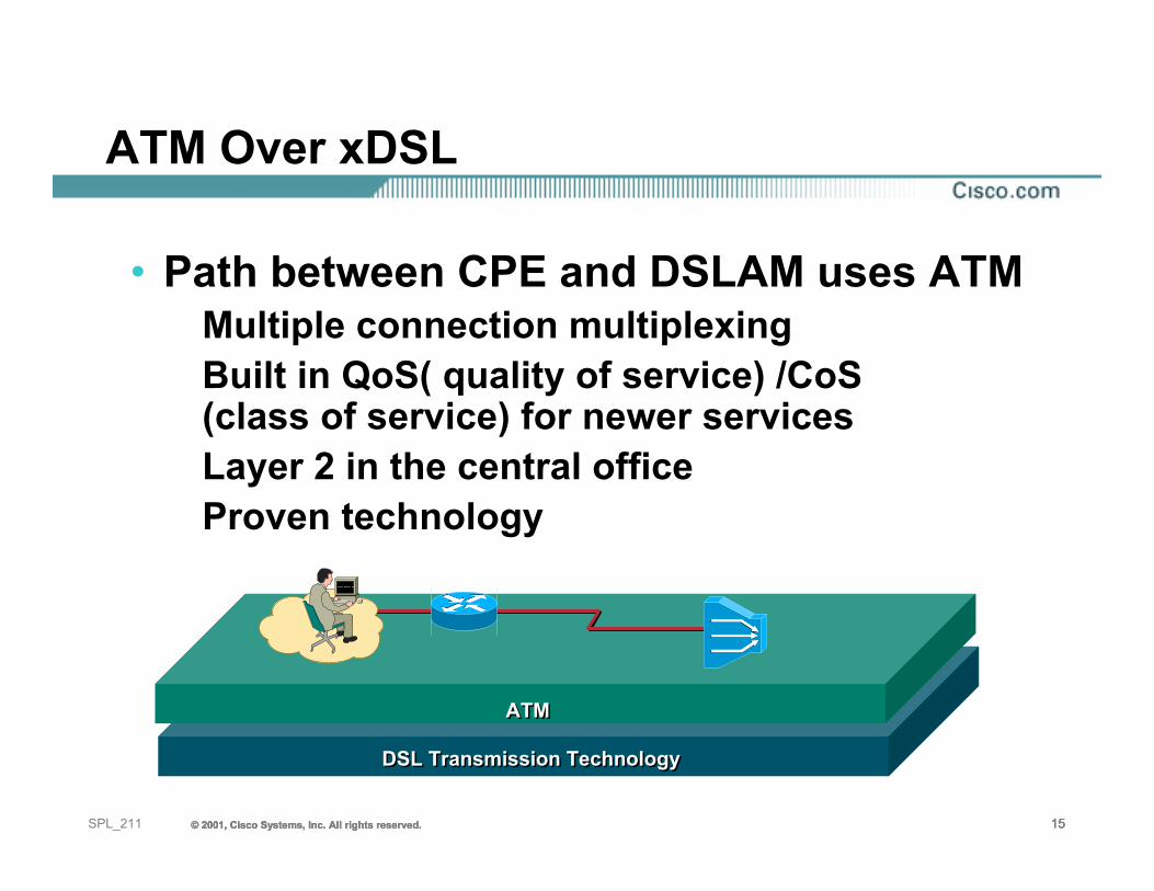
ATM Over xDSL
• Path between CPE and DSLAM uses ATMMultiple connection multiplexingBuilt in QoS( quality of service) /CoS (class of service) for newer servicesLayer 2 in the central officeProven technology
DSL Transmission TechnologyDSL Transmission Technology
ATMATM
© 2001, Cisco Systems, Inc. All rights reserved. 16© 2001, Cisco Systems, Inc. All rights reserved. 16© 2001, Cisco Systems, Inc. All rights reserved. 16SPL_211
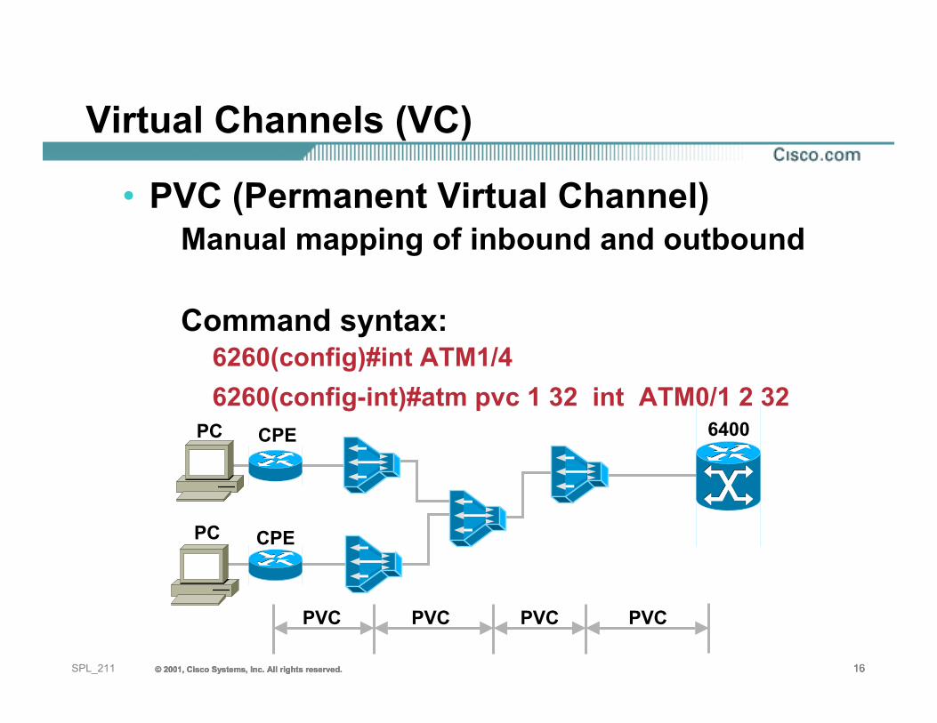
Virtual Channels (VC)
• PVC (Permanent Virtual Channel)Manual mapping of inbound and outbound
Command syntax:6260(config)#int ATM1/46260(config-int)#atm pvc 1 32 int ATM0/1 2 32
PVC PVC PVC PVC
PC CPE
6400PC CPE
© 2001, Cisco Systems, Inc. All rights reserved. 17© 2001, Cisco Systems, Inc. All rights reserved. 17© 2001, Cisco Systems, Inc. All rights reserved. 17SPL_211
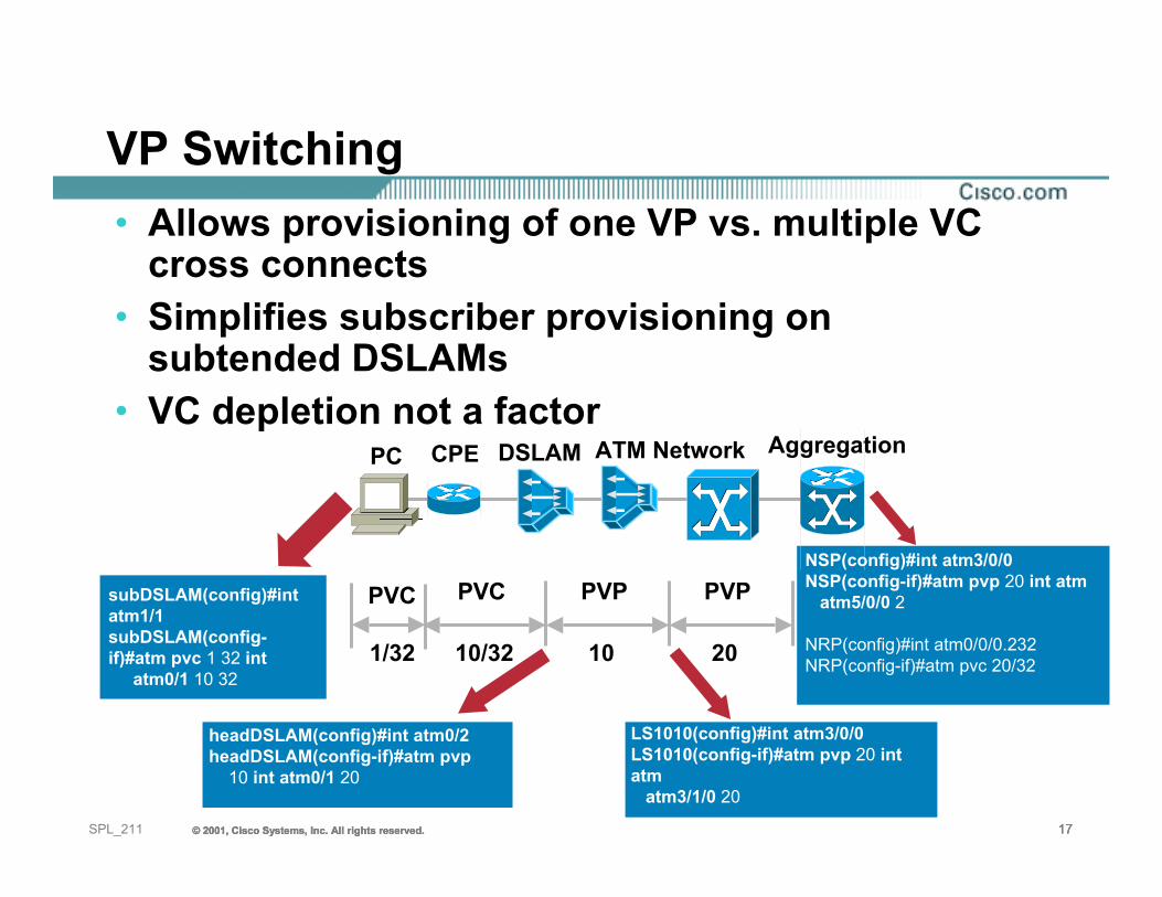
VP Switching• Allows provisioning of one VP vs. multiple VC
cross connects• Simplifies subscriber provisioning on
subtended DSLAMs• VC depletion not a factor
PVC
1/32
PVCsubDSLAM(config)#int atm1/1subDSLAM(config-if)#atm pvc 1 32 int
atm0/1 10 3210/32
PVP
10
headDSLAM(config)#int atm0/2 headDSLAM(config-if)#atm pvp
10 int atm0/1 20
PVP
20
LS1010(config)#int atm3/0/0LS1010(config-if)#atm pvp 20 int atm
atm3/1/0 20
NSP(config)#int atm3/0/0NSP(config-if)#atm pvp 20 int atm
atm5/0/0 2
NRP(config)#int atm0/0/0.232NRP(config-if)#atm pvc 20/32
PC CPE DSLAM ATM Network Aggregation
© 2001, Cisco Systems, Inc. All rights reserved. 18© 2001, Cisco Systems, Inc. All rights reserved. 18© 2001, Cisco Systems, Inc. All rights reserved. 18SPL_211
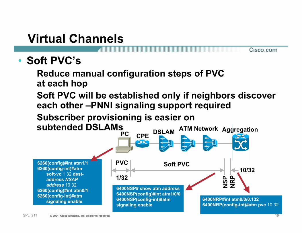
Virtual Channels• Soft PVC’s
Reduce manual configuration steps of PVCat each hopSoft PVC will be established only if neighbors discover each other –PNNI signaling support requiredSubscriber provisioning is easier onsubtended DSLAMs
PVC Soft PVC
NSP NR
P1/3210/32
6260(config)#int atm1/16260(config-int)#atm
soft-vc 1 32 dest-address NSAP address 10 32
6260(config)#int atm0/16260(config-int)#atm
signaling enable
6400NSP# show atm address6400NSP(config)#int atm1/0/06400NSP(config-int)#atmsignaling enable
6400NRP#int atm0/0/0.1326400NRP(config-int)#atm pvc 10 32
PC CPE DSLAM ATM Network Aggregation
© 2001, Cisco Systems, Inc. All rights reserved. 19© 2001, Cisco Systems, Inc. All rights reserved. 19© 2001, Cisco Systems, Inc. All rights reserved. 19SPL_211
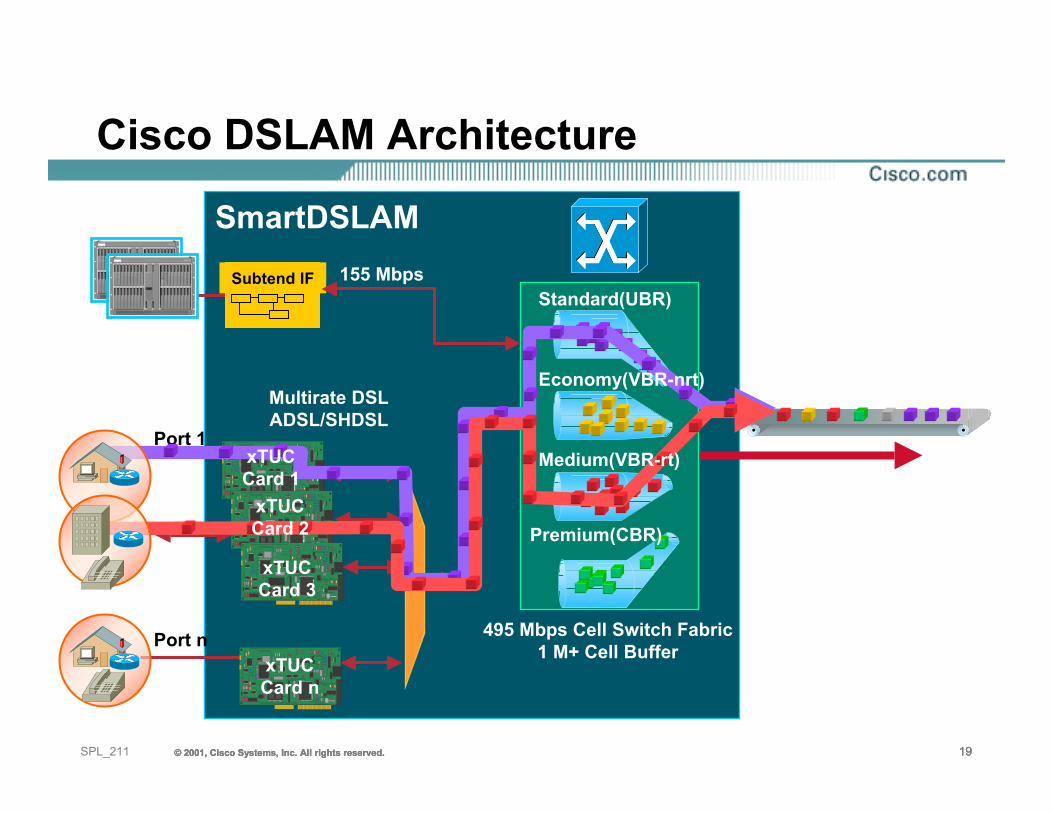
OC3, DS3, DS1,DS3, E1, E3WAN interface
Port 1
Port n
155 Mbps
xTUCCard 3
xTUCCard n
SmartDSLAM
Multirate DSLADSL/SHDSL
*Available 1HCY00
495 Mbps Cell Switch Fabric1 M+ Cell Buffer
Cisco DSLAM Architecture
Subtend IF
...
Standard(UBR)
Economy(VBR-nrt)
Medium(VBR-rt)
Premium(CBR)xTUCCard 2
xTUCCard 1
© 2001, Cisco Systems, Inc. All rights reserved. 20© 2001, Cisco Systems, Inc. All rights reserved. 20© 2001, Cisco Systems, Inc. All rights reserved. 20SPL_211
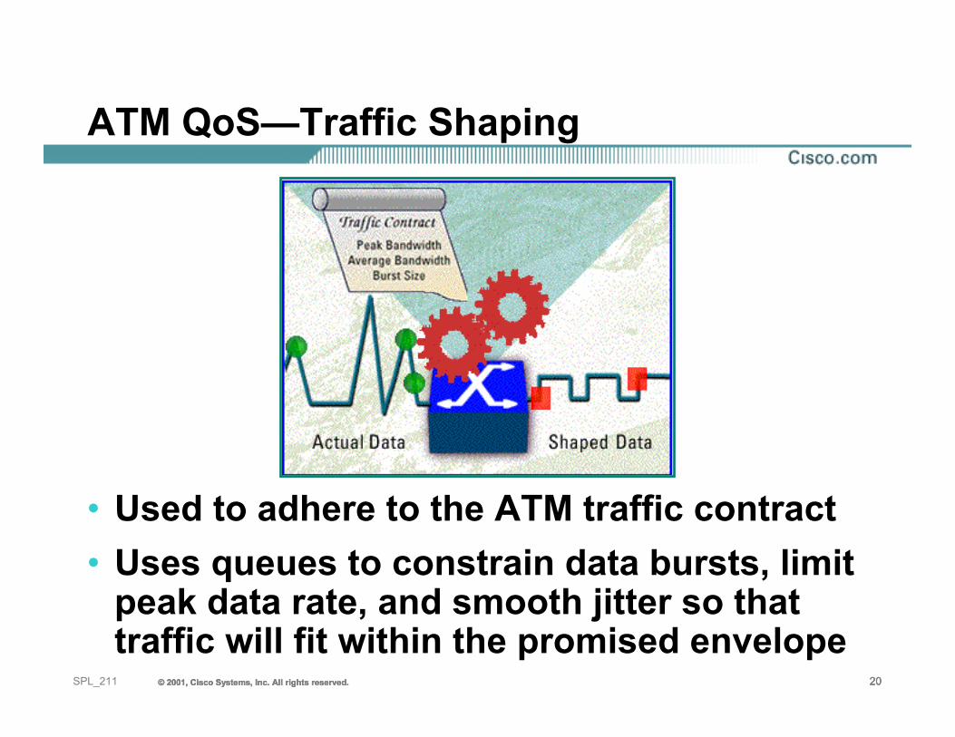
ATM QoS—Traffic Shaping
• Used to adhere to the ATM traffic contract • Uses queues to constrain data bursts, limit
peak data rate, and smooth jitter so that traffic will fit within the promised envelope
© 2001, Cisco Systems, Inc. All rights reserved. 21© 2001, Cisco Systems, Inc. All rights reserved. 21© 2001, Cisco Systems, Inc. All rights reserved. 21SPL_211
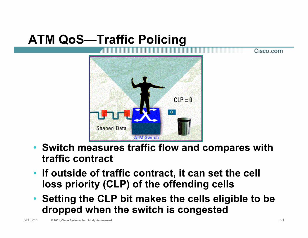
ATM QoS—Traffic Policing
• Switch measures traffic flow and compares with traffic contract
• If outside of traffic contract, it can set the cell loss priority (CLP) of the offending cells
• Setting the CLP bit makes the cells eligible to be dropped when the switch is congested
© 2001, Cisco Systems, Inc. All rights reserved. 22© 2001, Cisco Systems, Inc. All rights reserved. 22© 2001, Cisco Systems, Inc. All rights reserved. 22SPL_211
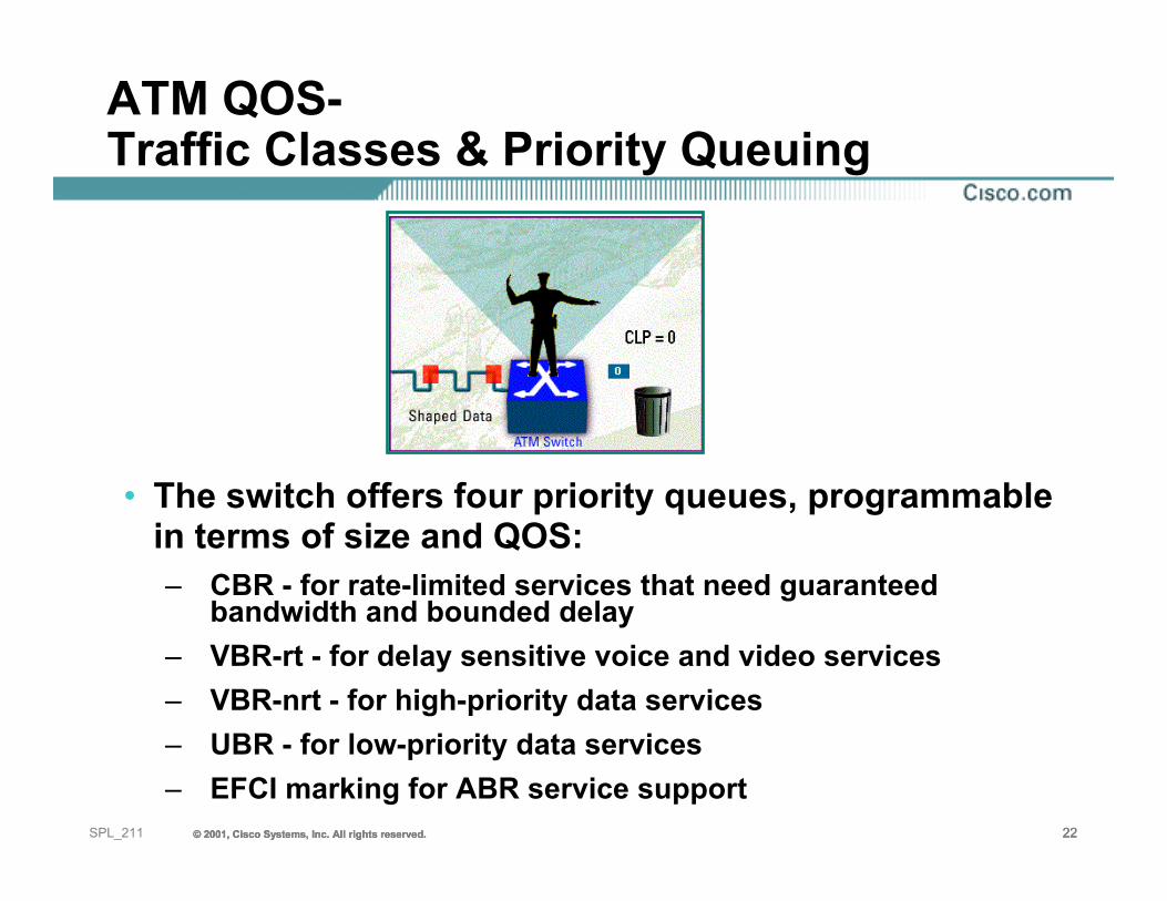
• The switch offers four priority queues, programmable in terms of size and QOS:– CBR - for rate-limited services that need guaranteed
bandwidth and bounded delay– VBR-rt - for delay sensitive voice and video services– VBR-nrt - for high-priority data services– UBR - for low-priority data services– EFCI marking for ABR service support
ATM QOS-Traffic Classes & Priority Queuing
© 2001, Cisco Systems, Inc. All rights reserved. 23© 2001, Cisco Systems, Inc. All rights reserved. 23© 2001, Cisco Systems, Inc. All rights reserved. 23SPL_211
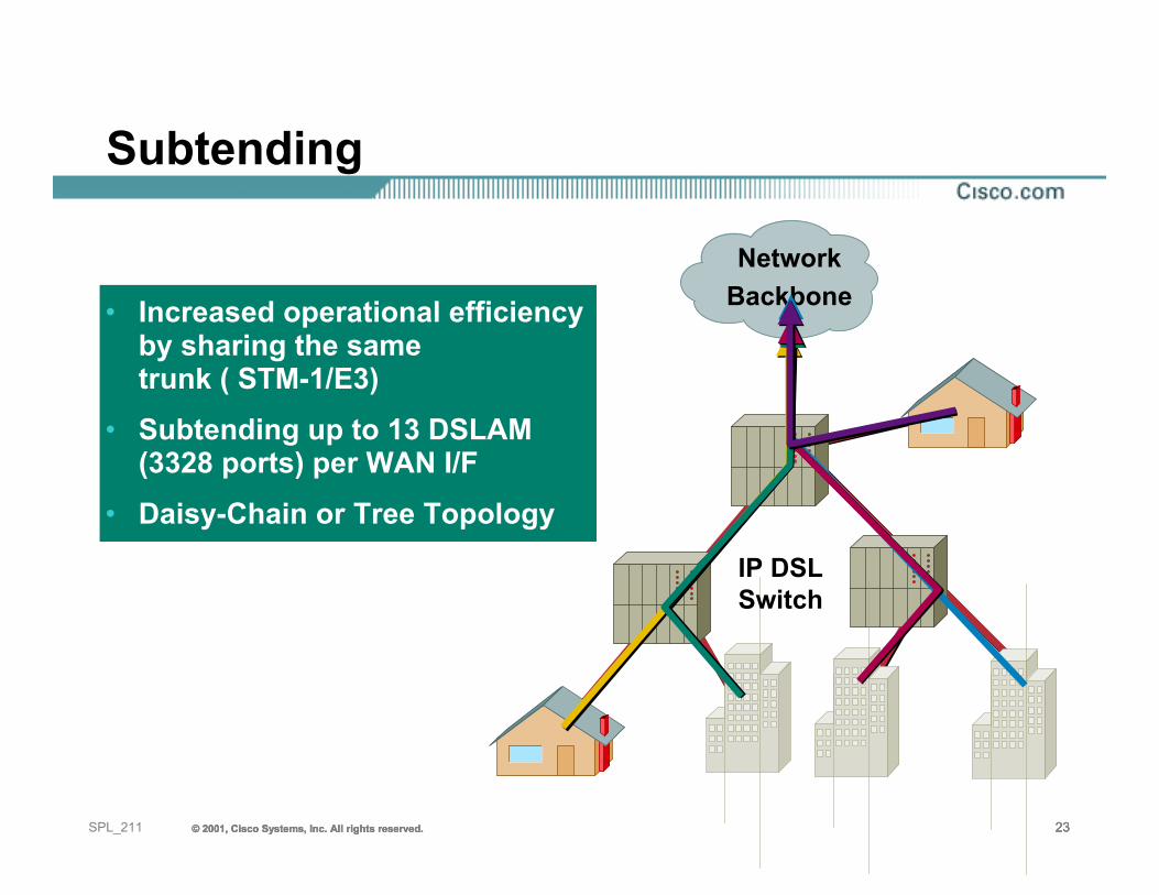
Subtending
• Increased operational efficiencyby sharing the sametrunk ( STM-1/E3)
• Subtending up to 13 DSLAM(3328 ports) per WAN I/F
• Daisy-Chain or Tree Topology
IP DSL Switch
NetworkBackbone
© 2001, Cisco Systems, Inc. All rights reserved. 24© 2001, Cisco Systems, Inc. All rights reserved. 24© 2001, Cisco Systems, Inc. All rights reserved. 24SPL_211
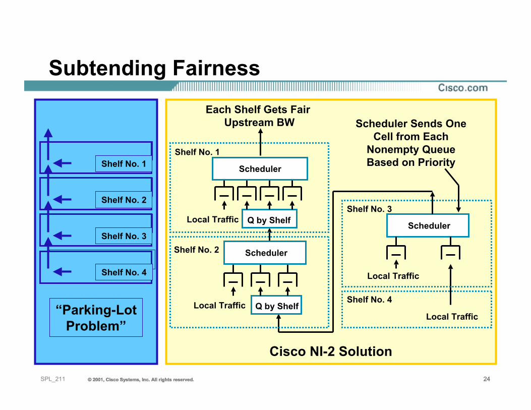
Subtending Fairness
1/2 Upstream BW
1/4 Upstream BW
1/16 Upstream BW
1/8 Upstream BW
Shelf No. 4
Shelf No. 3
Shelf No. 2
Shelf No. 1
“Parking-LotProblem”
Cisco NI-2 Solution
Q by Shelf
Q by Shelf
Local Traffic
Scheduler
Local Traffic
Local Traffic
Local Traffic
Shelf No. 1
Shelf No. 4
Shelf No. 3
Each Shelf Gets Fair Upstream BW Scheduler Sends One
Cell from Each Nonempty QueueBased on PriorityScheduler
SchedulerShelf No. 2
© 2001, Cisco Systems, Inc. All rights reserved. 25© 2001, Cisco Systems, Inc. All rights reserved. 25© 2001, Cisco Systems, Inc. All rights reserved. 25SPL_211
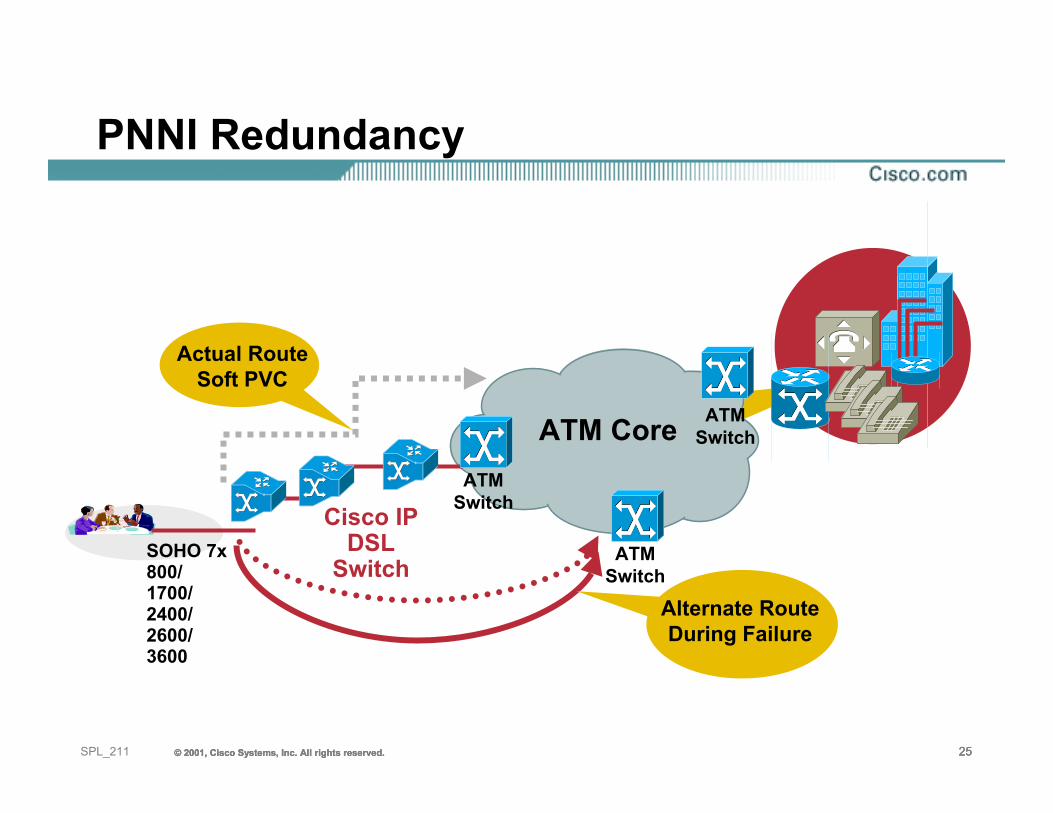
PNNI Redundancy
ATM Core
Cisco IP DSL
SwitchSOHO 7x800/1700/2400/2600/3600
Actual RouteSoft PVC
Alternate RouteDuring Failure
ATMSwitch
ATMSwitch
ATMSwitch
© 2001, Cisco Systems, Inc. All rights reserved. 26© 2001, Cisco Systems, Inc. All rights reserved. 26© 2001, Cisco Systems, Inc. All rights reserved. 26SPL_211
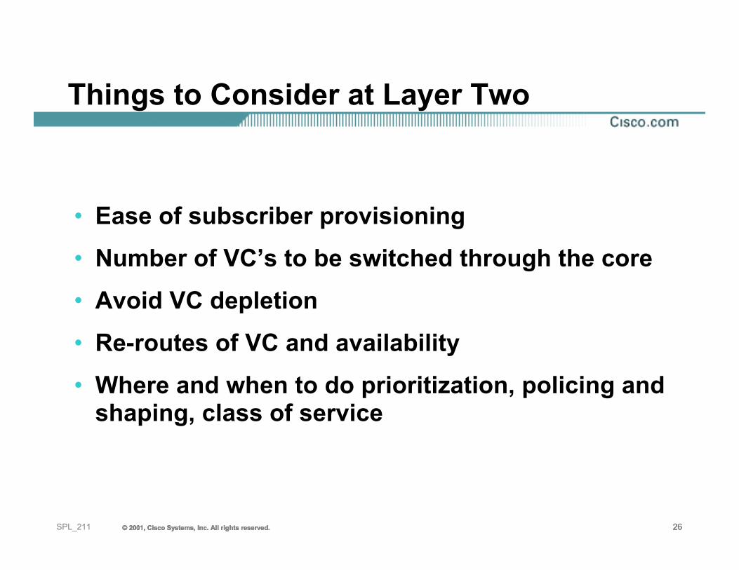
Things to Consider at Layer Two
• Ease of subscriber provisioning• Number of VC’s to be switched through the core• Avoid VC depletion• Re-routes of VC and availability• Where and when to do prioritization, policing and
shaping, class of service
© 2001, Cisco Systems, Inc. All rights reserved. 27© 2001, Cisco Systems, Inc. All rights reserved. 27© 2001, Cisco Systems, Inc. All rights reserved. 27SPL_211
Agenda
• Digital Subscriber Line Technologies• Subscriber Connection Models• Reaching the Services• Case Studies• Summary
© 2001, Cisco Systems, Inc. All rights reserved. 28© 2001, Cisco Systems, Inc. All rights reserved. 28© 2001, Cisco Systems, Inc. All rights reserved. 28SPL_211
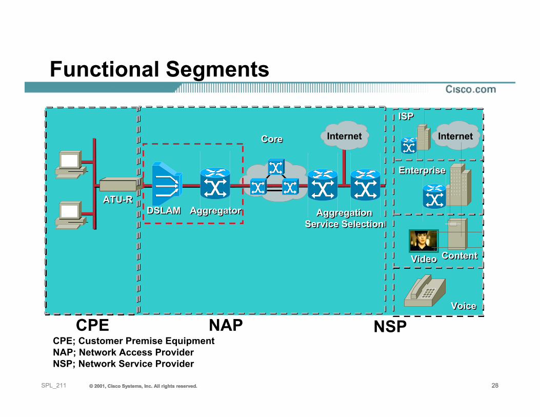
Functional Segments
CPE; Customer Premise EquipmentNAP; Network Access ProviderNSP; Network Service Provider
CPE NAP NSP
VideoVideo
VoiceVoice
ContentContent
ATU-RATU-R
CoreCore
AggregationService Selection
AggregationService Selection
EnterpriseEnterprise
ISPISP
AggregatorAggregatorDSLAMDSLAM
Internet Internet
© 2001, Cisco Systems, Inc. All rights reserved. 29© 2001, Cisco Systems, Inc. All rights reserved. 29© 2001, Cisco Systems, Inc. All rights reserved. 29SPL_211
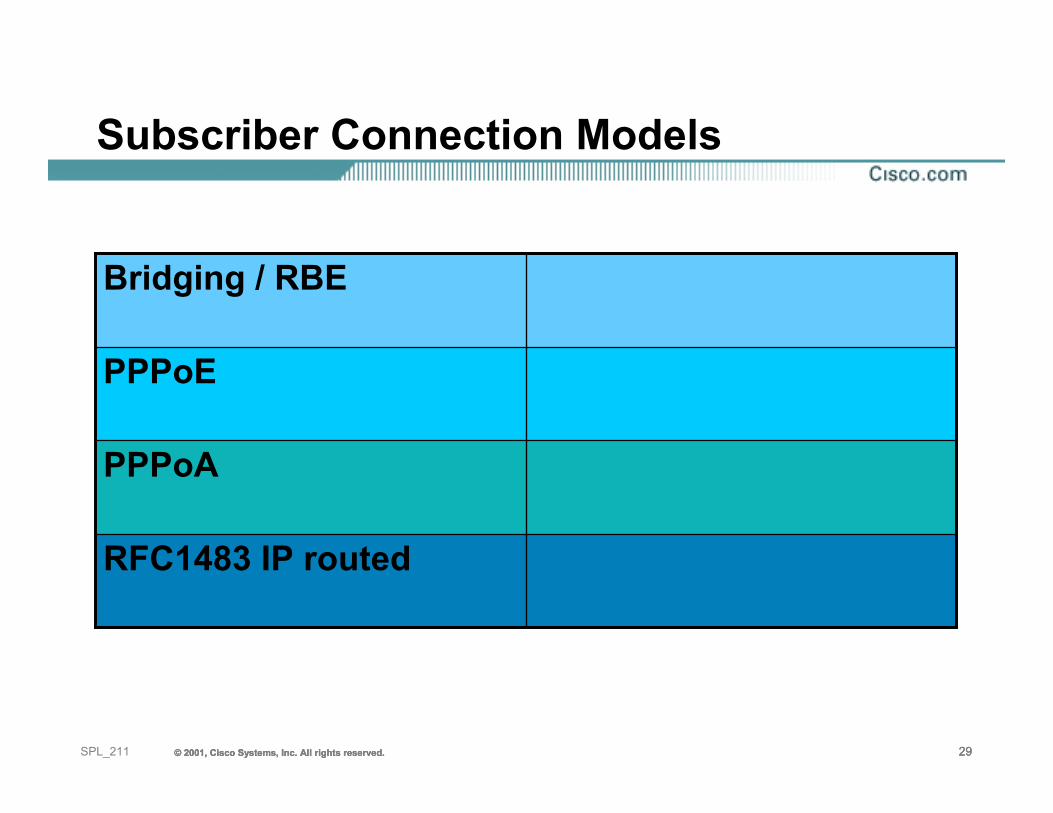
Subscriber Connection Models
RFC1483 IP routed
PPPoA
PPPoE
Bridging / RBE
© 2001, Cisco Systems, Inc. All rights reserved. 30© 2001, Cisco Systems, Inc. All rights reserved. 30© 2001, Cisco Systems, Inc. All rights reserved. 30SPL_211
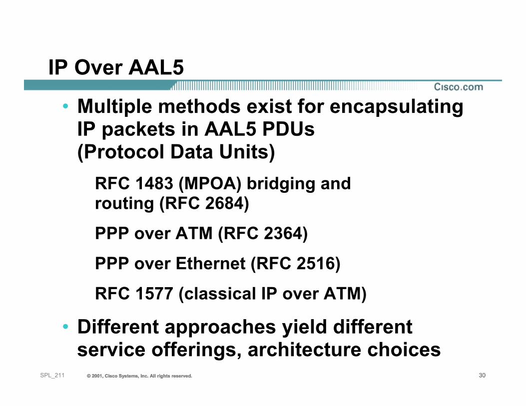
IP Over AAL5
• Multiple methods exist for encapsulating IP packets in AAL5 PDUs (Protocol Data Units)
RFC 1483 (MPOA) bridging and routing (RFC 2684)PPP over ATM (RFC 2364)PPP over Ethernet (RFC 2516)RFC 1577 (classical IP over ATM)
• Different approaches yield different service offerings, architecture choices
31SPL_211 © 2001, Cisco Systems, Inc. All rights reserved.© 2001, Cisco Systems, Inc. All rights reserved.© 2001, Cisco Systems, Inc. All rights reserved.
RFC1483(2684)bridging (based on RFC1483 bridging)
© 2001, Cisco Systems, Inc. All rights reserved. 32© 2001, Cisco Systems, Inc. All rights reserved. 32© 2001, Cisco Systems, Inc. All rights reserved. 32SPL_211
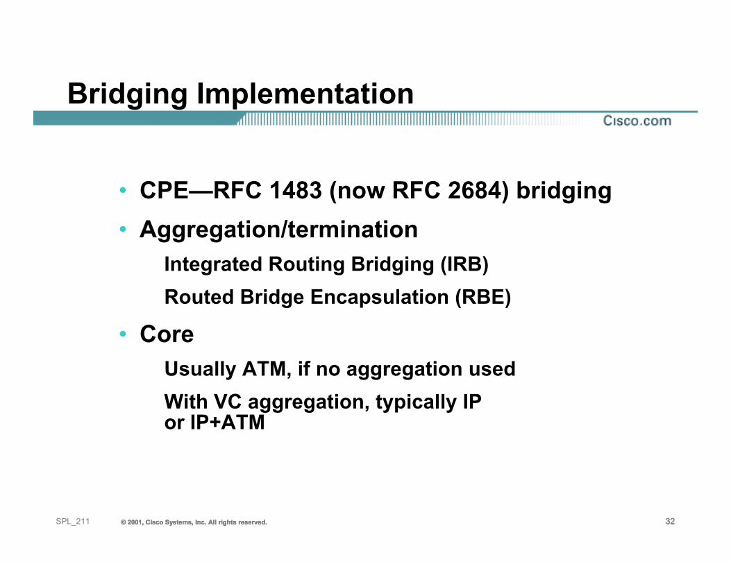
Bridging Implementation
• CPE—RFC 1483 (now RFC 2684) bridging• Aggregation/termination
Integrated Routing Bridging (IRB)Routed Bridge Encapsulation (RBE)
• Core Usually ATM, if no aggregation usedWith VC aggregation, typically IP or IP+ATM
© 2001, Cisco Systems, Inc. All rights reserved. 33© 2001, Cisco Systems, Inc. All rights reserved. 33© 2001, Cisco Systems, Inc. All rights reserved. 33SPL_211
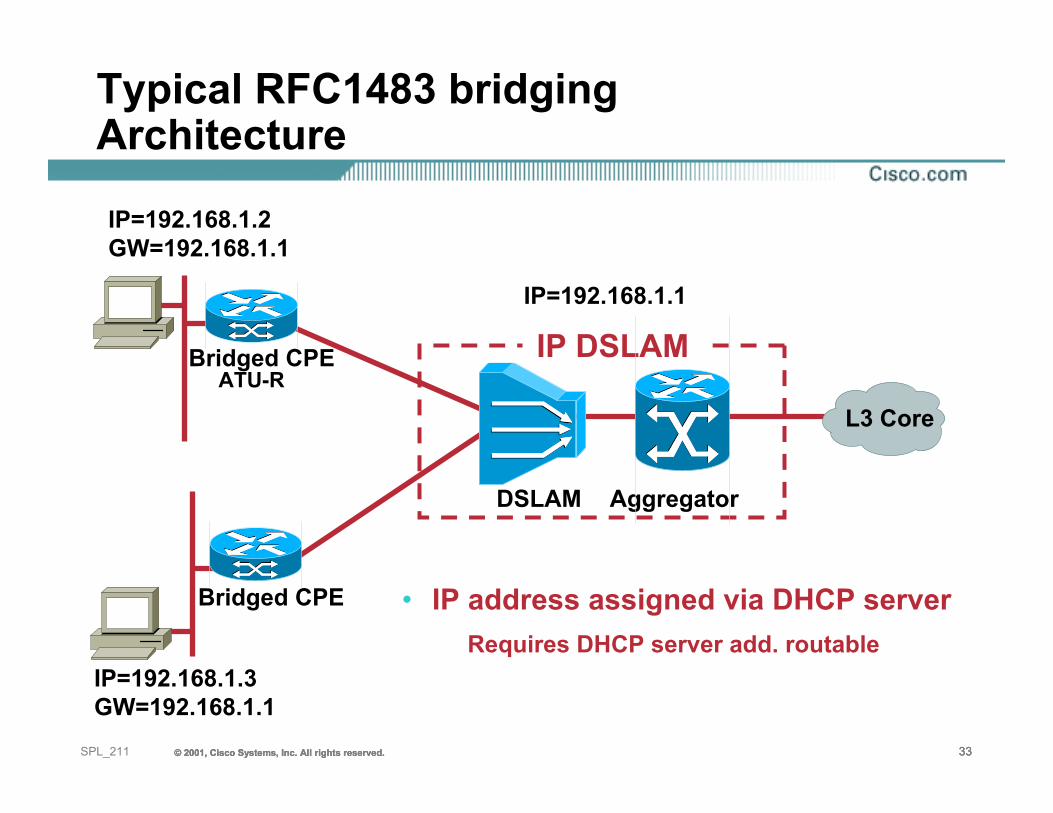
Typical RFC1483 bridging Architecture
• IP address assigned via DHCP serverRequires DHCP server add. routable
ATU-RBridged CPE
Bridged CPE
IP=192.168.1.2GW=192.168.1.1
IP=192.168.1.1
IP=192.168.1.3GW=192.168.1.1
DSLAM Aggregator
IP DSLAM
L3 Core
© 2001, Cisco Systems, Inc. All rights reserved. 34© 2001, Cisco Systems, Inc. All rights reserved. 34© 2001, Cisco Systems, Inc. All rights reserved. 34SPL_211
How Does RFC1483 Bridging Work?
• Subscriber traffic is carried in a BPDU (Bridged Protocol Data Unit)
• The ATM interface is treated as a bridged interface
© 2001, Cisco Systems, Inc. All rights reserved. 35© 2001, Cisco Systems, Inc. All rights reserved. 35© 2001, Cisco Systems, Inc. All rights reserved. 35SPL_211
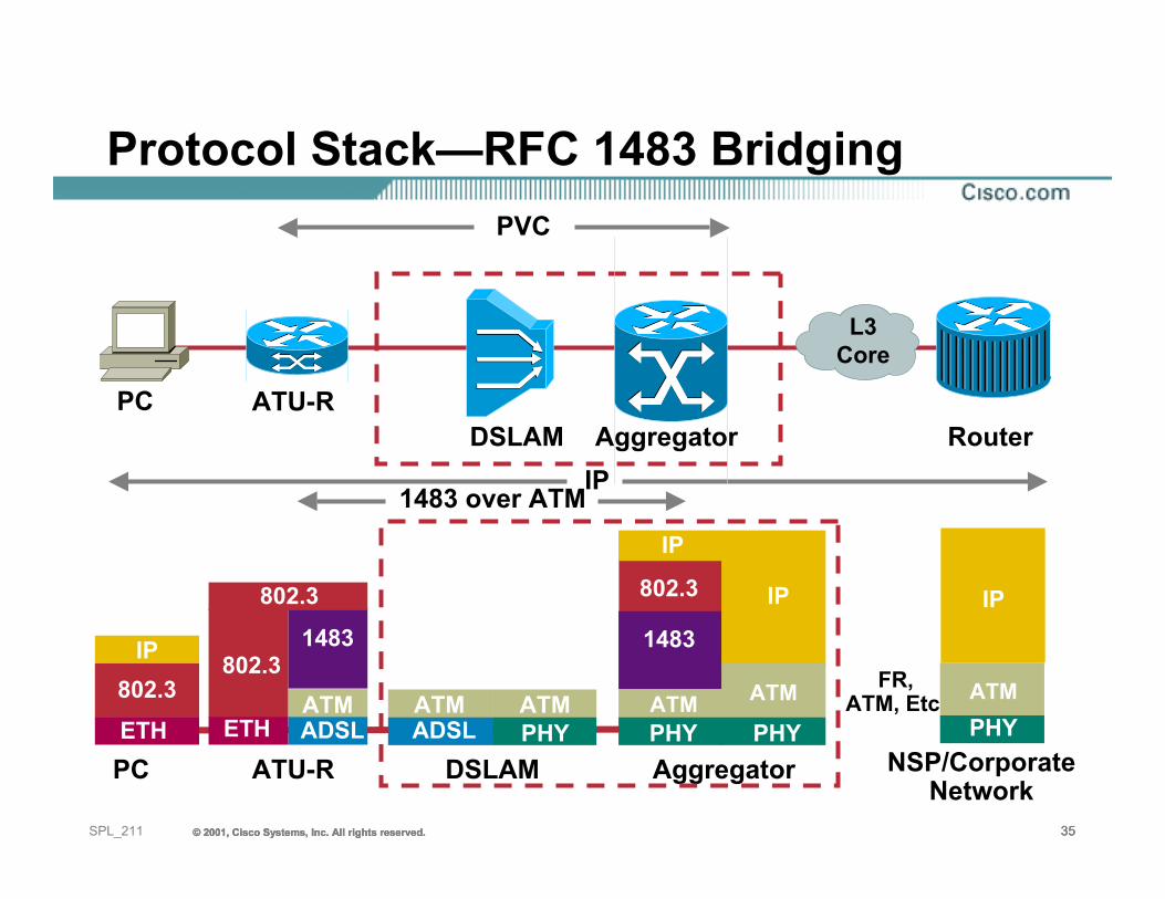
Protocol Stack—RFC 1483 Bridging
PC NSP/CorporateNetwork
ATU-R
1483 over ATMIP
PC ATU-RRouter
PVC
FR, ATM, Etc.
1483
ATMADSL
802.3
ETH
802.3
IP
PHYATM
IP
IP802.3ETH
DSLAM Aggregator
AggregatorDSLAM
802.3
IP
1483
PHY PHYATM
IP
ATMADSL
ATMPHY
ATM
L3Core
© 2001, Cisco Systems, Inc. All rights reserved. 36© 2001, Cisco Systems, Inc. All rights reserved. 36© 2001, Cisco Systems, Inc. All rights reserved. 36SPL_211
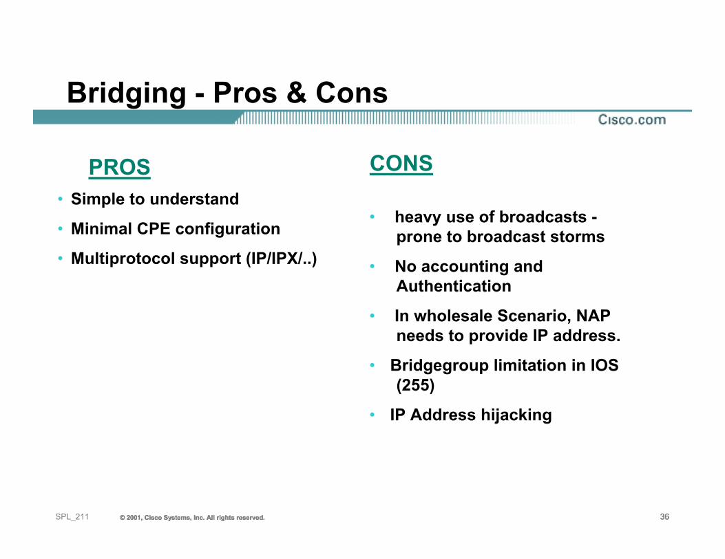
• Simple to understand
• Minimal CPE configuration
• Multiprotocol support (IP/IPX/..)
• heavy use of broadcasts -prone to broadcast storms
• No accounting and Authentication
• In wholesale Scenario, NAP needs to provide IP address.
• Bridgegroup limitation in IOS (255)
• IP Address hijacking
PROS CONS
Bridging - Pros & Cons
37SPL_211 © 2001, Cisco Systems, Inc. All rights reserved.© 2001, Cisco Systems, Inc. All rights reserved.© 2001, Cisco Systems, Inc. All rights reserved.
Route Bridge Encapsulation RBE
(based on RFC1483 bridging)
© 2001, Cisco Systems, Inc. All rights reserved. 38© 2001, Cisco Systems, Inc. All rights reserved. 38© 2001, Cisco Systems, Inc. All rights reserved. 38SPL_211
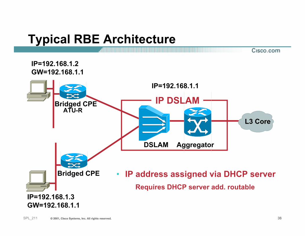
Typical RBE Architecture
• IP address assigned via DHCP serverRequires DHCP server add. routable
ATU-RBridged CPE
Bridged CPE
IP=192.168.1.2GW=192.168.1.1
IP=192.168.1.1
IP=192.168.1.3GW=192.168.1.1
DSLAM Aggregator
IP DSLAM
L3 Core
© 2001, Cisco Systems, Inc. All rights reserved. 39© 2001, Cisco Systems, Inc. All rights reserved. 39© 2001, Cisco Systems, Inc. All rights reserved. 39SPL_211
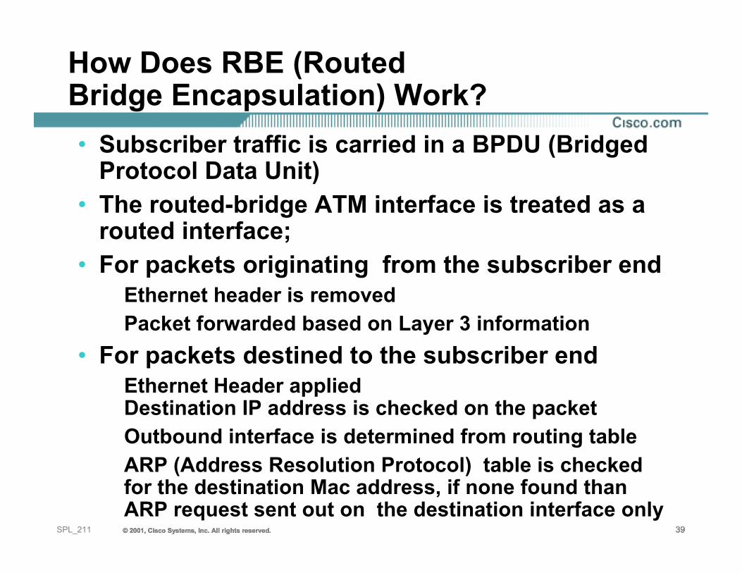
How Does RBE (Routed Bridge Encapsulation) Work?• Subscriber traffic is carried in a BPDU (Bridged
Protocol Data Unit)• The routed-bridge ATM interface is treated as a
routed interface;• For packets originating from the subscriber end
Ethernet header is removedPacket forwarded based on Layer 3 information
• For packets destined to the subscriber end Ethernet Header appliedDestination IP address is checked on the packetOutbound interface is determined from routing tableARP (Address Resolution Protocol) table is checked for the destination Mac address, if none found than ARP request sent out on the destination interface only
© 2001, Cisco Systems, Inc. All rights reserved. 40© 2001, Cisco Systems, Inc. All rights reserved. 40© 2001, Cisco Systems, Inc. All rights reserved. 40SPL_211
RBE IP Address Management
• IP addresses provided by DHCPServer can be
On NAP networkOn NSP network
• If using DHCP relay, the remote server must be reachable and must have a return route
© 2001, Cisco Systems, Inc. All rights reserved. 41© 2001, Cisco Systems, Inc. All rights reserved. 41© 2001, Cisco Systems, Inc. All rights reserved. 41SPL_211
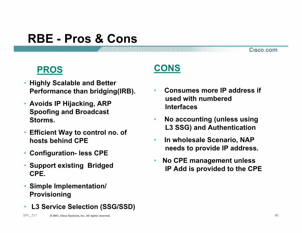
• Highly Scalable and Better Performance than bridging(IRB).
• Avoids IP Hijacking, ARP Spoofing and Broadcast Storms.
• Efficient Way to control no. of hosts behind CPE
• Configuration- less CPE
• Support existing Bridged CPE.
• Simple Implementation/ Provisioning
• L3 Service Selection (SSG/SSD)
• Consumes more IP address if used with numbered Interfaces
• No accounting (unless using L3 SSG) and Authentication
• In wholesale Scenario, NAP needs to provide IP address.
• No CPE management unless IP Add is provided to the CPE
PROS CONS
RBE - Pros & Cons
© 2001, Cisco Systems, Inc. All rights reserved. 42© 2001, Cisco Systems, Inc. All rights reserved. 42© 2001, Cisco Systems, Inc. All rights reserved. 42SPL_211
When To Use RBE/Bridging?
• Bridged CPE’s are the CPE’s of choice for residential services, no management required
• If the ATU-R is very simple and can only perform RFC1483 (now RFC 2684) Bridging.
• The NAP/NSP does not want to maintain the client software on the subscriber computer.
• Only one PVC from the Subscriber CPE to the NAP. No requirement for routing on multiple PVC’s.
© 2001, Cisco Systems, Inc. All rights reserved. 43© 2001, Cisco Systems, Inc. All rights reserved. 43© 2001, Cisco Systems, Inc. All rights reserved. 43SPL_211
PPP ( Point to Point Protocol) Implementation
• Three access methods:• Subscriber
PPPoE, PPPoE, L2TP client• Aggregation
PPP sessions terminatedPPP sessions tunneled over to NSP
• CoreEnd–to–end ATM PVC, PPP terminated at NSP IP, ATM or IP+ATM; (L2TP, L2F, MPLS/VPN)
44SPL_211 © 2001, Cisco Systems, Inc. All rights reserved.© 2001, Cisco Systems, Inc. All rights reserved.© 2001, Cisco Systems, Inc. All rights reserved.
PPP over EthernetPPPoE
© 2001, Cisco Systems, Inc. All rights reserved. 45© 2001, Cisco Systems, Inc. All rights reserved. 45© 2001, Cisco Systems, Inc. All rights reserved. 45SPL_211
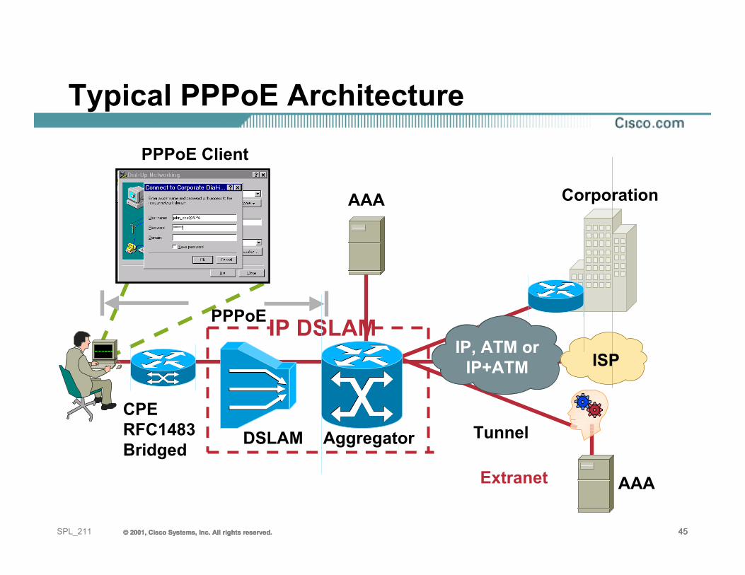
Typical PPPoE Architecture
CorporationAAA
Tunnel
PPPoE Client
Extranet
ISP
CPERFC1483Bridged
IP, ATM orIP+ATM
DSLAM Aggregator
IP DSLAM
AAA
PPPoE
© 2001, Cisco Systems, Inc. All rights reserved. 46© 2001, Cisco Systems, Inc. All rights reserved. 46© 2001, Cisco Systems, Inc. All rights reserved. 46SPL_211
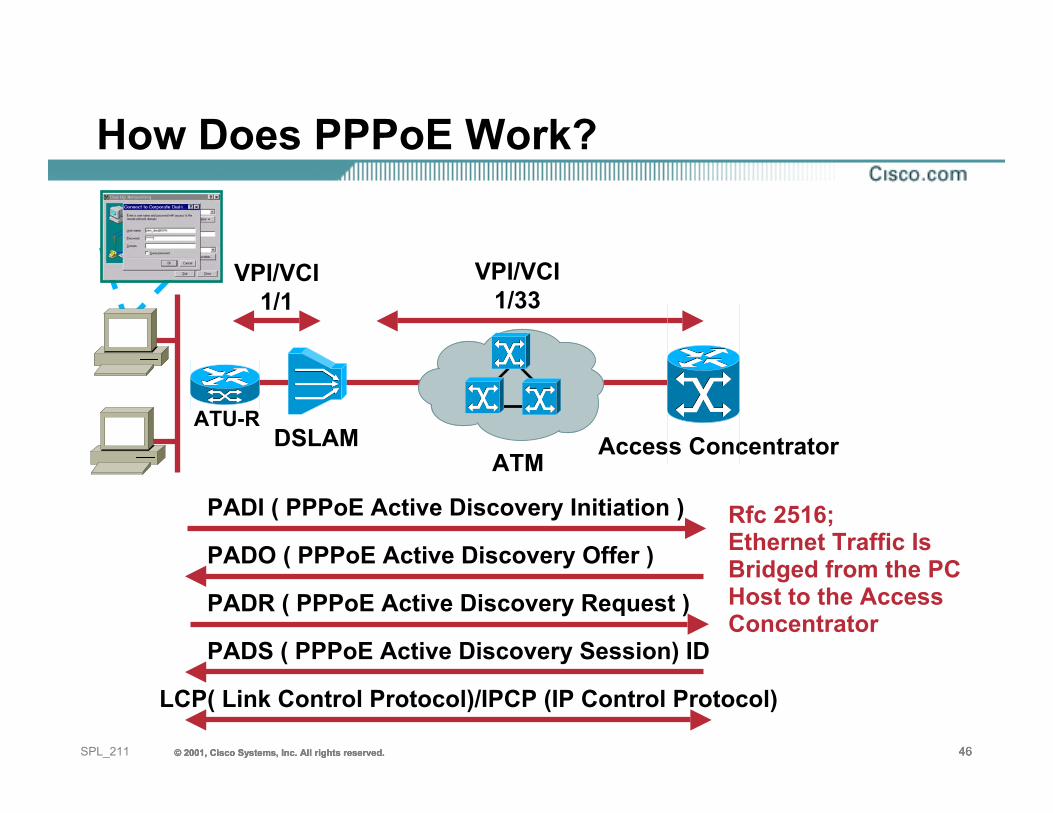
How Does PPPoE Work?
ATU-RDSLAM
ATM Access Concentrator
VPI/VCI1/1
VPI/VCI1/33
PADI ( PPPoE Active Discovery Initiation )
PADO ( PPPoE Active Discovery Offer )
PADR ( PPPoE Active Discovery Request )
PADS ( PPPoE Active Discovery Session) ID
LCP( Link Control Protocol)/IPCP (IP Control Protocol)
Rfc 2516;Ethernet Traffic Is Bridged from the PC Host to the Access Concentrator
© 2001, Cisco Systems, Inc. All rights reserved. 47© 2001, Cisco Systems, Inc. All rights reserved. 47© 2001, Cisco Systems, Inc. All rights reserved. 47SPL_211
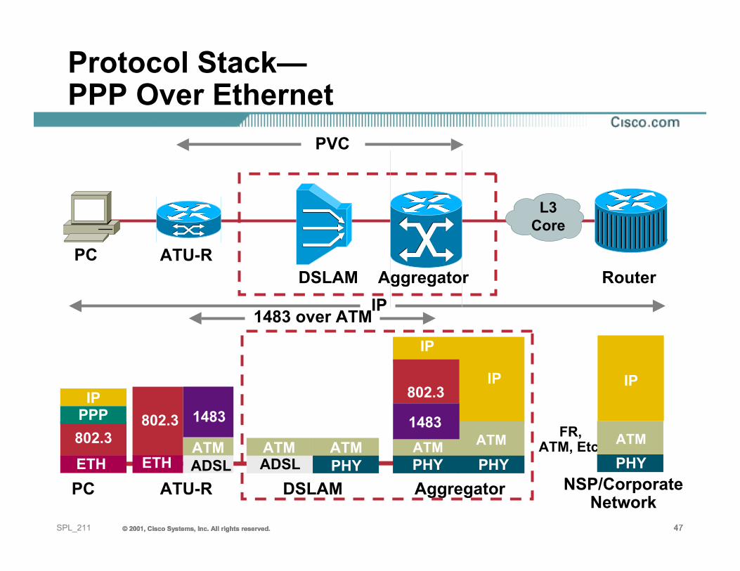
Protocol Stack—PPP Over Ethernet
PC NSP/CorporateNetwork
ATU-R
1483 over ATMIP
PC ATU-RRouter
PVC
FR, ATM, Etc.
1483
ATMADSL
802.3
ETH
IP
PHYATM
IPIP
802.3ETH
DSLAM Aggregator
AggregatorDSLAM
IP
PHY PHYATM
IP
ATMADSL
ATMPHY
ATM
L3Core
802.3PPP 1483
© 2001, Cisco Systems, Inc. All rights reserved. 48© 2001, Cisco Systems, Inc. All rights reserved. 48© 2001, Cisco Systems, Inc. All rights reserved. 48SPL_211
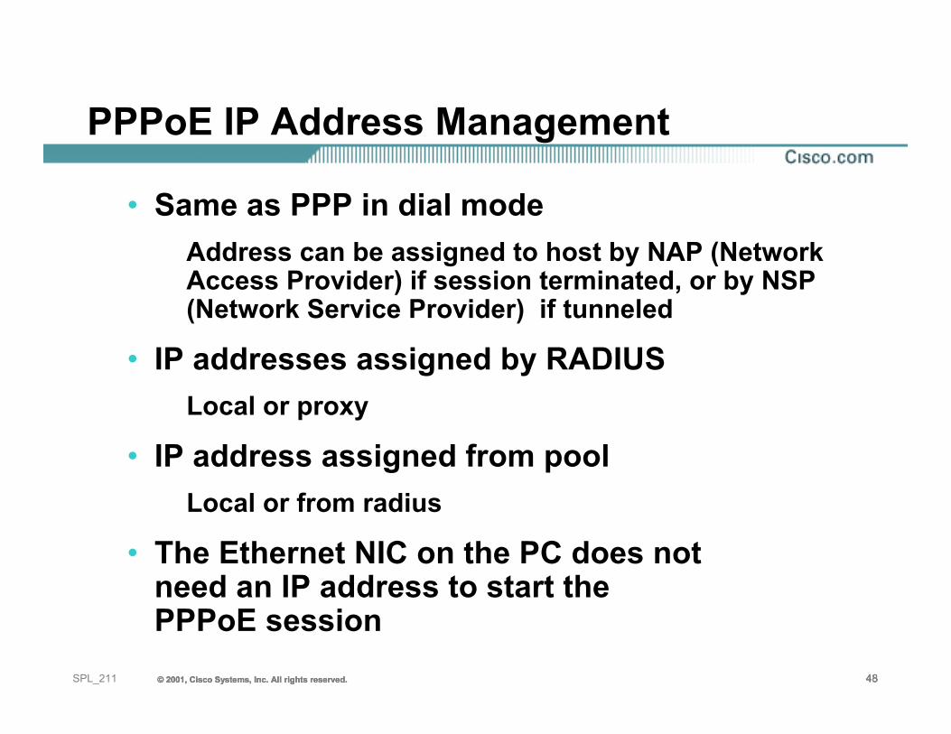
PPPoE IP Address Management
• Same as PPP in dial modeAddress can be assigned to host by NAP (Network Access Provider) if session terminated, or by NSP (Network Service Provider) if tunneled
• IP addresses assigned by RADIUSLocal or proxy
• IP address assigned from poolLocal or from radius
• The Ethernet NIC on the PC does not need an IP address to start the PPPoE session
© 2001, Cisco Systems, Inc. All rights reserved. 49© 2001, Cisco Systems, Inc. All rights reserved. 49© 2001, Cisco Systems, Inc. All rights reserved. 49SPL_211
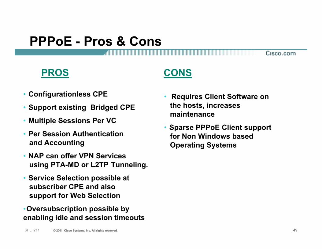
• Configurationless CPE
• Support existing Bridged CPE
• Multiple Sessions Per VC
• Per Session Authentication and Accounting
• NAP can offer VPN Services using PTA-MD or L2TP Tunneling.
• Service Selection possible at subscriber CPE and also support for Web Selection
•Oversubscription possible by enabling idle and session timeouts
• Requires Client Software on the hosts, increases maintenance
• Sparse PPPoE Client support for Non Windows based Operating Systems
PROS CONS
PPPoE - Pros & Cons
© 2001, Cisco Systems, Inc. All rights reserved. 50© 2001, Cisco Systems, Inc. All rights reserved. 50© 2001, Cisco Systems, Inc. All rights reserved. 50SPL_211
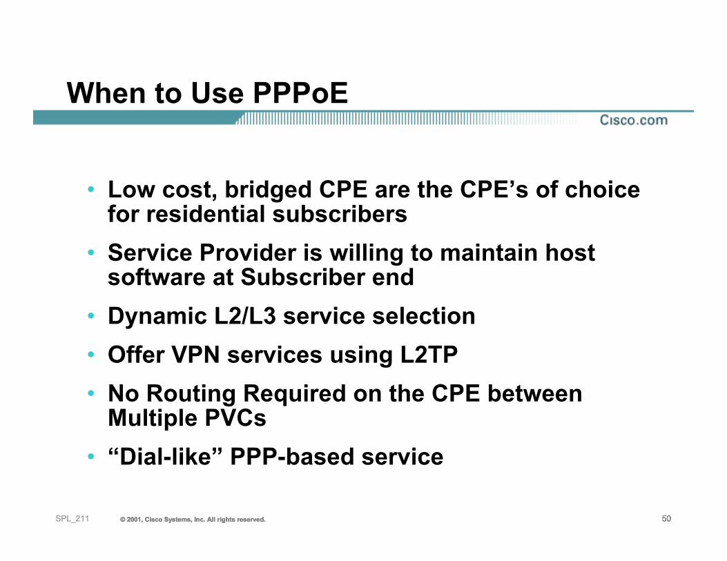
When to Use PPPoE
• Low cost, bridged CPE are the CPE’s of choice for residential subscribers
• Service Provider is willing to maintain host software at Subscriber end
• Dynamic L2/L3 service selection• Offer VPN services using L2TP• No Routing Required on the CPE between
Multiple PVCs• “Dial-like” PPP-based service
51SPL_211 © 2001, Cisco Systems, Inc. All rights reserved.© 2001, Cisco Systems, Inc. All rights reserved.© 2001, Cisco Systems, Inc. All rights reserved.
PPP over AAL5PPPoA
© 2001, Cisco Systems, Inc. All rights reserved. 52© 2001, Cisco Systems, Inc. All rights reserved. 52© 2001, Cisco Systems, Inc. All rights reserved. 52SPL_211
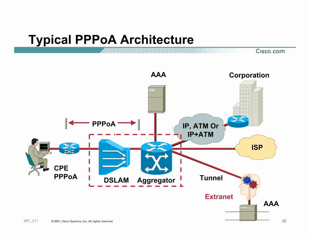
CorporationAAA
PPPoA
Tunnel
Extranet
ISP
CPEPPPoA
Typical PPPoA Architecture
IP, ATM OrIP+ATM
DSLAM Aggregator
AAA
© 2001, Cisco Systems, Inc. All rights reserved. 53© 2001, Cisco Systems, Inc. All rights reserved. 53© 2001, Cisco Systems, Inc. All rights reserved. 53SPL_211
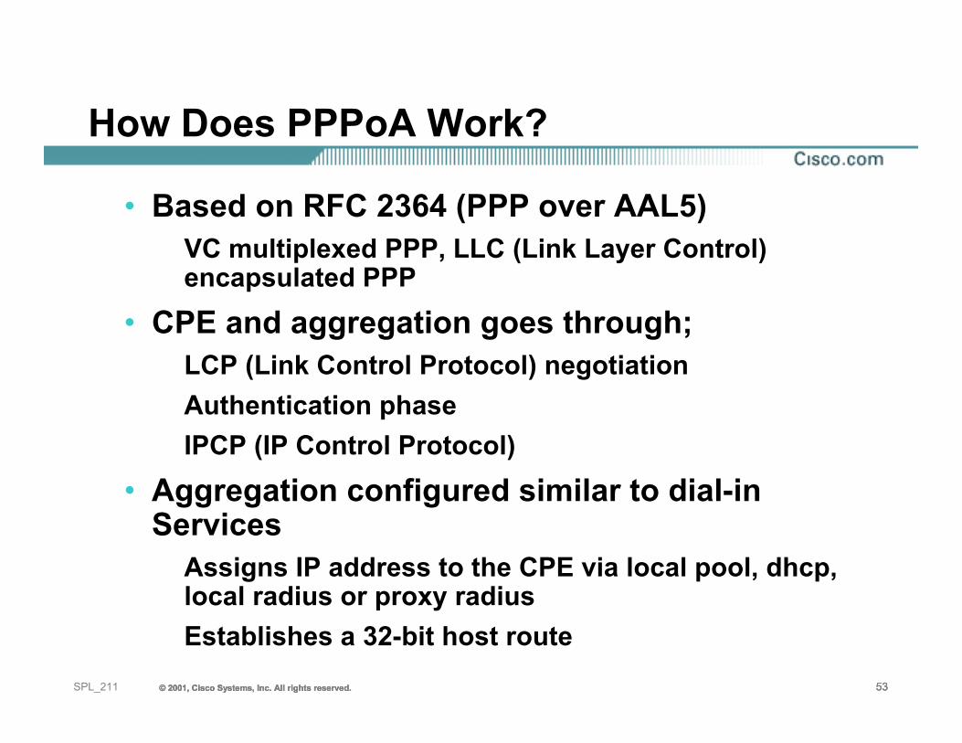
How Does PPPoA Work?
• Based on RFC 2364 (PPP over AAL5)VC multiplexed PPP, LLC (Link Layer Control) encapsulated PPP
• CPE and aggregation goes through;LCP (Link Control Protocol) negotiationAuthentication phaseIPCP (IP Control Protocol)
• Aggregation configured similar to dial-in Services
Assigns IP address to the CPE via local pool, dhcp, local radius or proxy radiusEstablishes a 32-bit host route
© 2001, Cisco Systems, Inc. All rights reserved. 54© 2001, Cisco Systems, Inc. All rights reserved. 54© 2001, Cisco Systems, Inc. All rights reserved. 54SPL_211
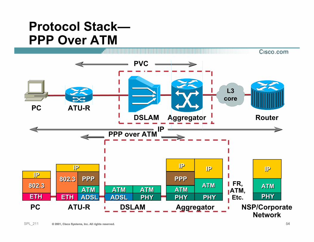
PPPPPP
AggregatorPC DSLAM NSP/CorporateNetwork
ATU-R
FR, ATM, Etc.
Protocol Stack—PPP Over ATM
PPP over ATMIP
PC
L3core
ATU-RRouter
PVC
IPIP802.3802.3
ETHETHATMATMADSLADSL
802.3802.3
ETHETH
IPIP
ATMATMADSLADSL
ATMATMPHYPHY
PPPPPP
PHYPHY
ATMATM
IPIPIPIP
PHYPHYATMATM
IP
PHYPHYATMATM
IPIP
DSLAM Aggregator
© 2001, Cisco Systems, Inc. All rights reserved. 55© 2001, Cisco Systems, Inc. All rights reserved. 55© 2001, Cisco Systems, Inc. All rights reserved. 55SPL_211
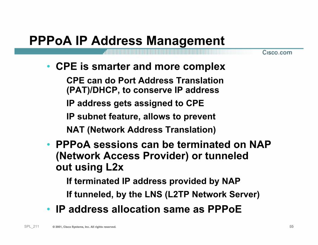
PPPoA IP Address Management
• CPE is smarter and more complexCPE can do Port Address Translation (PAT)/DHCP, to conserve IP addressIP address gets assigned to CPEIP subnet feature, allows to prevent NAT (Network Address Translation)
• PPPoA sessions can be terminated on NAP (Network Access Provider) or tunneledout using L2x
If terminated IP address provided by NAPIf tunneled, by the LNS (L2TP Network Server)
• IP address allocation same as PPPoE
© 2001, Cisco Systems, Inc. All rights reserved. 56© 2001, Cisco Systems, Inc. All rights reserved. 56© 2001, Cisco Systems, Inc. All rights reserved. 56SPL_211
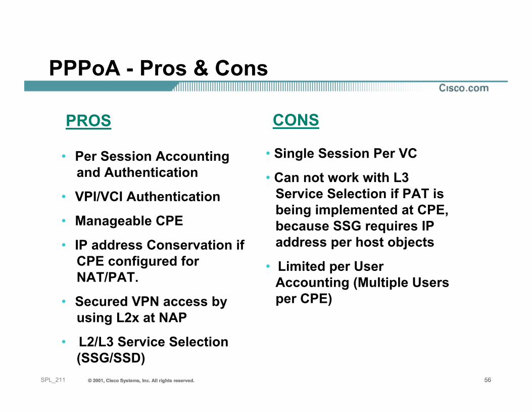
• Per Session Accounting and Authentication
• VPI/VCI Authentication
• Manageable CPE
• IP address Conservation if CPE configured for NAT/PAT.
• Secured VPN access by using L2x at NAP
• L2/L3 Service Selection (SSG/SSD)
• Single Session Per VC
• Can not work with L3 Service Selection if PAT is being implemented at CPE, because SSG requires IP address per host objects
• Limited per User Accounting (Multiple Users per CPE)
PROS CONS
PPPoA - Pros & Cons
© 2001, Cisco Systems, Inc. All rights reserved. 57© 2001, Cisco Systems, Inc. All rights reserved. 57© 2001, Cisco Systems, Inc. All rights reserved. 57SPL_211
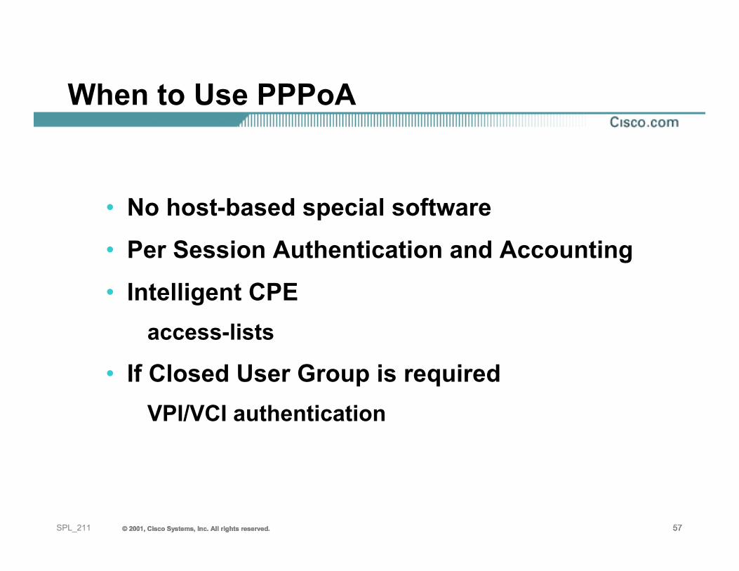
When to Use PPPoA
• No host-based special software• Per Session Authentication and Accounting• Intelligent CPE
access-lists
• If Closed User Group is requiredVPI/VCI authentication
58SPL_211 © 2001, Cisco Systems, Inc. All rights reserved.© 2001, Cisco Systems, Inc. All rights reserved.© 2001, Cisco Systems, Inc. All rights reserved.
RFC2684 (RFC1483)Routed
© 2001, Cisco Systems, Inc. All rights reserved. 59© 2001, Cisco Systems, Inc. All rights reserved. 59© 2001, Cisco Systems, Inc. All rights reserved. 59SPL_211
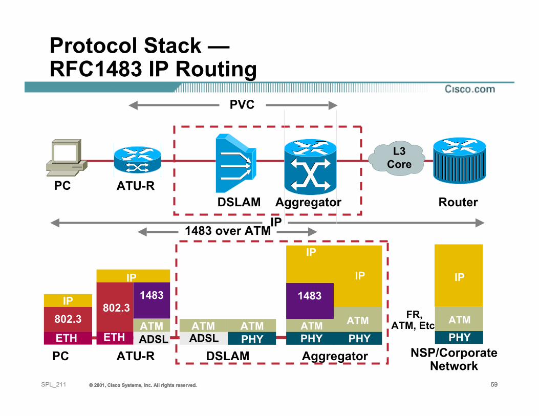
Protocol Stack —RFC1483 IP Routing
PC NSP/CorporateNetwork
ATU-R
1483 over ATMIP
PC ATU-RRouter
PVC
FR, ATM, Etc.
1483
ATMADSL
802.3
ETH
IP
PHYATM
IP
IP802.3ETH
DSLAM Aggregator
AggregatorDSLAM
IP
1483
PHY PHYATM
IP
ATMADSL
ATMPHY
ATM
L3Core
IP
© 2001, Cisco Systems, Inc. All rights reserved. 60© 2001, Cisco Systems, Inc. All rights reserved. 60© 2001, Cisco Systems, Inc. All rights reserved. 60SPL_211
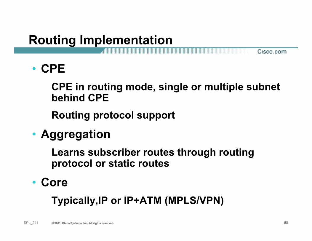
Routing Implementation
• CPECPE in routing mode, single or multiple subnetbehind CPERouting protocol support
• AggregationLearns subscriber routes through routing protocol or static routes
• CoreTypically,IP or IP+ATM (MPLS/VPN)
© 2001, Cisco Systems, Inc. All rights reserved. 61© 2001, Cisco Systems, Inc. All rights reserved. 61© 2001, Cisco Systems, Inc. All rights reserved. 61SPL_211
When To Use RFC1483 IP Routing?
• Routing implemented mainly for enterprise customers.
• If access provider wants to offer VPN services to enterprise, or different ISPs.
© 2001, Cisco Systems, Inc. All rights reserved. 62© 2001, Cisco Systems, Inc. All rights reserved. 62© 2001, Cisco Systems, Inc. All rights reserved. 62SPL_211
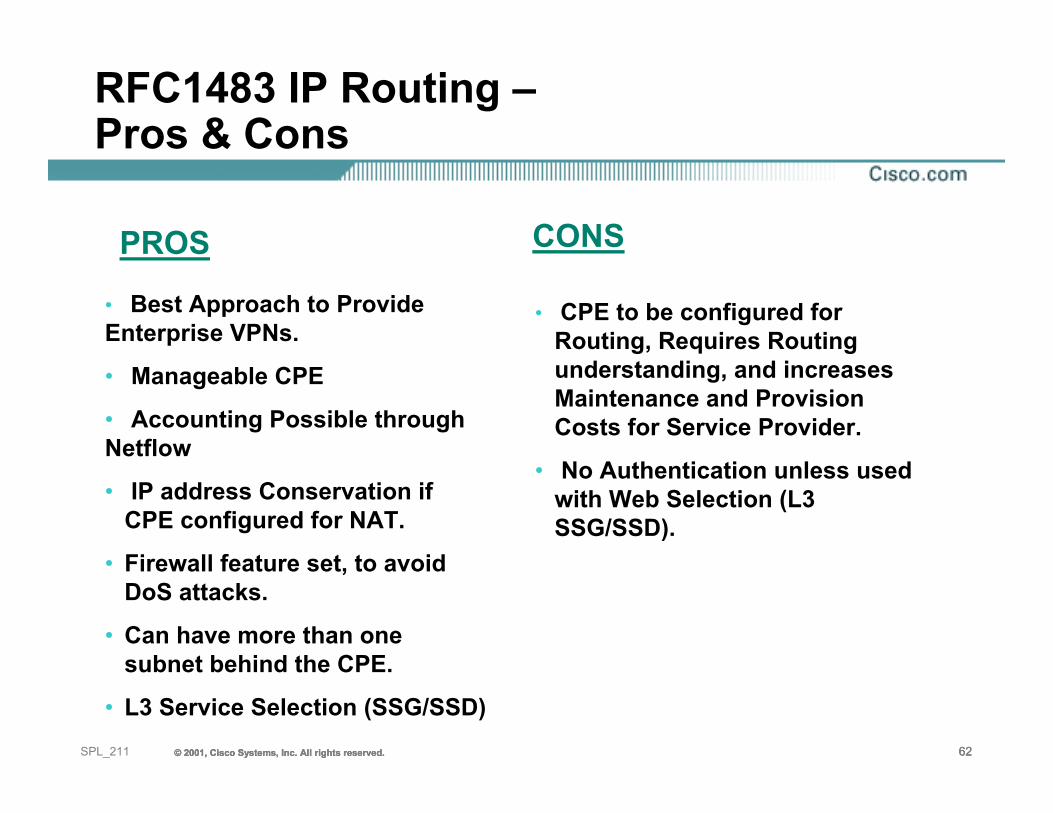
RFC1483 IP Routing –Pros & Cons
• Best Approach to Provide Enterprise VPNs.
• Manageable CPE
• Accounting Possible through Netflow
• IP address Conservation if CPE configured for NAT.
• Firewall feature set, to avoid DoS attacks.
• Can have more than one subnet behind the CPE.
• L3 Service Selection (SSG/SSD)
• CPE to be configured for Routing, Requires Routing understanding, and increases Maintenance and Provision Costs for Service Provider.
• No Authentication unless used with Web Selection (L3 SSG/SSD).
PROS CONS
© 2001, Cisco Systems, Inc. All rights reserved. 63© 2001, Cisco Systems, Inc. All rights reserved. 63© 2001, Cisco Systems, Inc. All rights reserved. 63SPL_211
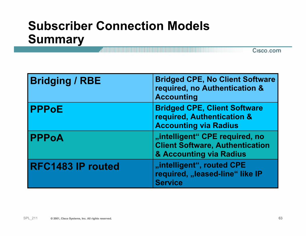
Subscriber Connection ModelsSummary
„intelligent“, routed CPE required, „leased-line“ like IP Service
RFC1483 IP routed
„intelligent“ CPE required, no Client Software, Authentication & Accounting via Radius
PPPoA
Bridged CPE, Client Software required, Authentication & Accounting via Radius
PPPoE
Bridged CPE, No Client Software required, no Authentication & Accounting
Bridging / RBE
© 2001, Cisco Systems, Inc. All rights reserved. 64© 2001, Cisco Systems, Inc. All rights reserved. 64© 2001, Cisco Systems, Inc. All rights reserved. 64SPL_211
Agenda
• Digital Subscriber Line Technologies• Subscriber Connection Models• Reaching the Services• Case Studies• Summary
© 2001, Cisco Systems, Inc. All rights reserved. 65© 2001, Cisco Systems, Inc. All rights reserved. 65© 2001, Cisco Systems, Inc. All rights reserved. 65SPL_211
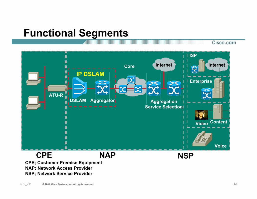
Functional Segments
CPE; Customer Premise EquipmentNAP; Network Access ProviderNSP; Network Service Provider
CPE NAP NSP
Video
Voice
Content
ATU-R
Core
AggregationService Selection
Enterprise
ISP
Aggregator
IP DSLAM
DSLAM
Internet Internet
© 2001, Cisco Systems, Inc. All rights reserved. 66© 2001, Cisco Systems, Inc. All rights reserved. 66© 2001, Cisco Systems, Inc. All rights reserved. 66SPL_211
Getting Across the Core
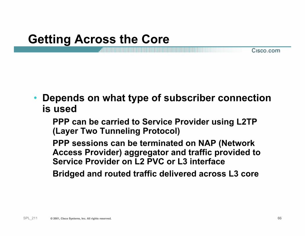
• Depends on what type of subscriber connection is used
PPP can be carried to Service Provider using L2TP (Layer Two Tunneling Protocol)PPP sessions can be terminated on NAP (Network Access Provider) aggregator and traffic provided to Service Provider on L2 PVC or L3 interfaceBridged and routed traffic delivered across L3 core
© 2001, Cisco Systems, Inc. All rights reserved. 67© 2001, Cisco Systems, Inc. All rights reserved. 67© 2001, Cisco Systems, Inc. All rights reserved. 67SPL_211
Design Considerations forDifferent Service Architectures
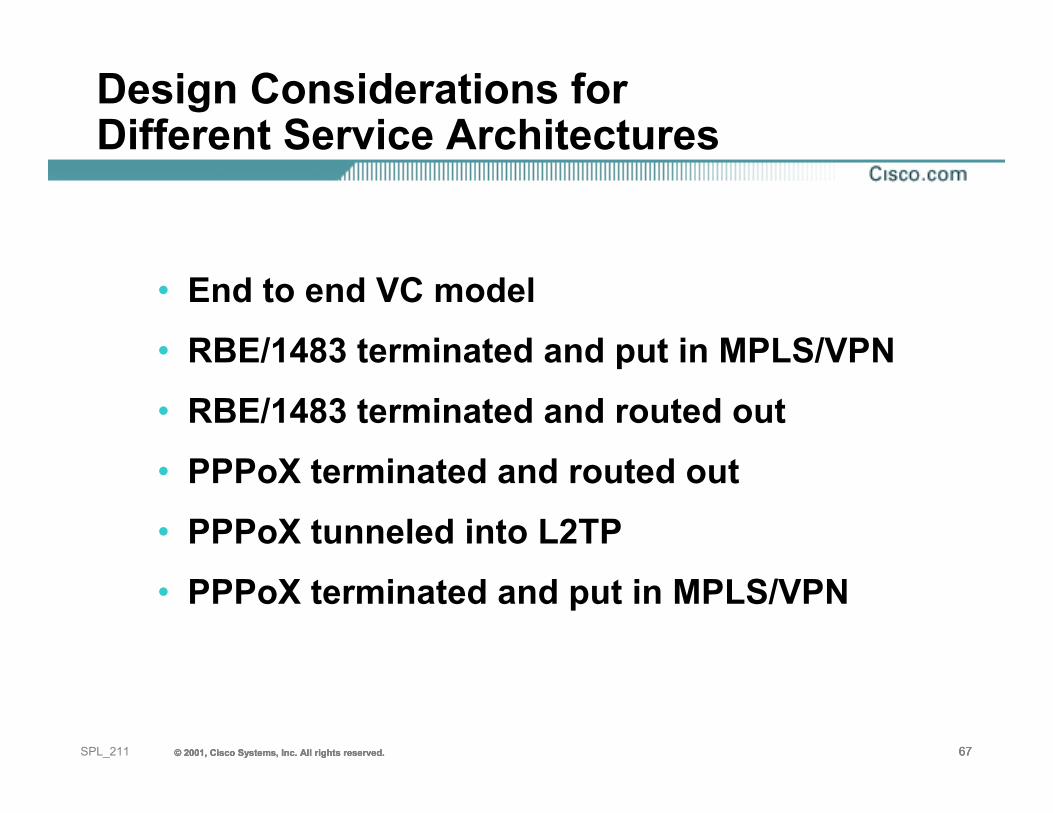
• End to end VC model• RBE/1483 terminated and put in MPLS/VPN• RBE/1483 terminated and routed out• PPPoX terminated and routed out• PPPoX tunneled into L2TP• PPPoX terminated and put in MPLS/VPN
© 2001, Cisco Systems, Inc. All rights reserved. 68© 2001, Cisco Systems, Inc. All rights reserved. 68© 2001, Cisco Systems, Inc. All rights reserved. 68SPL_211
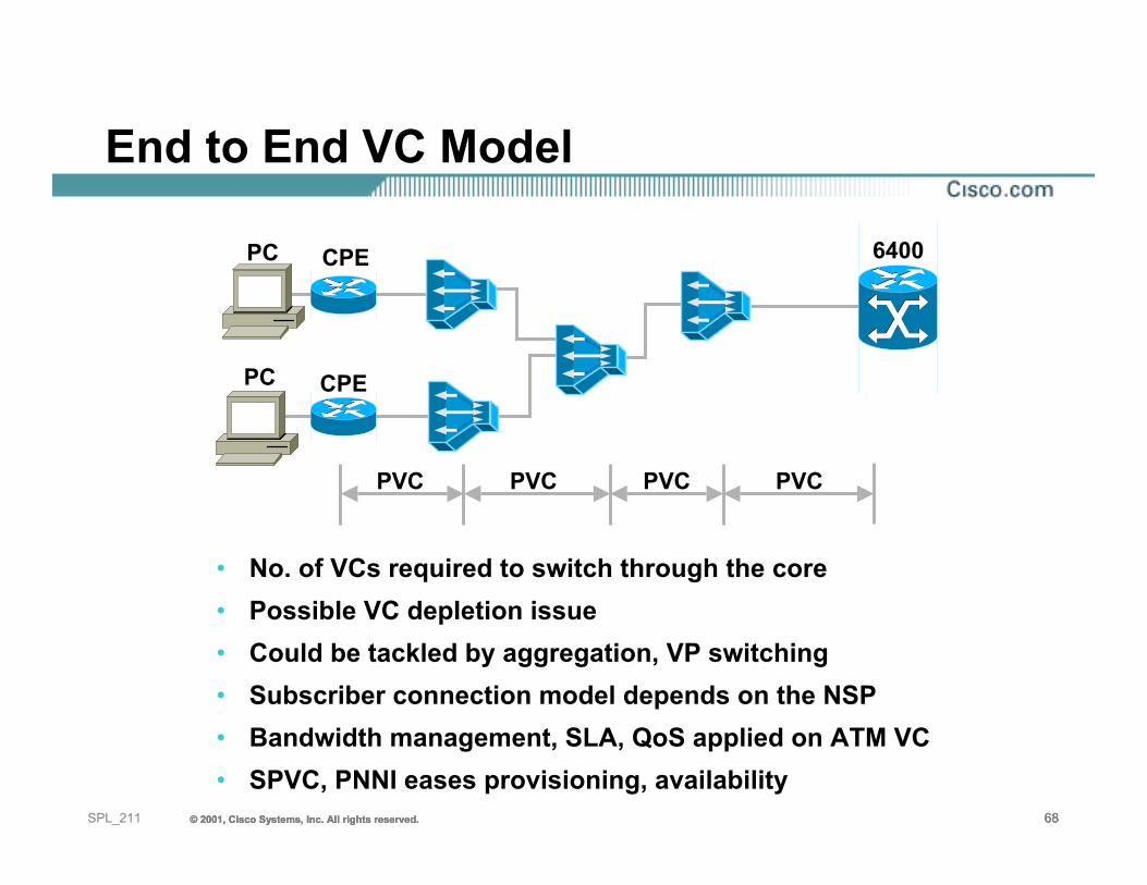
End to End VC Model
• No. of VCs required to switch through the core• Possible VC depletion issue• Could be tackled by aggregation, VP switching• Subscriber connection model depends on the NSP• Bandwidth management, SLA, QoS applied on ATM VC• SPVC, PNNI eases provisioning, availability
PVC PVC PVC PVC
PC CPE
6400PC CPE
© 2001, Cisco Systems, Inc. All rights reserved. 69© 2001, Cisco Systems, Inc. All rights reserved. 69© 2001, Cisco Systems, Inc. All rights reserved. 69SPL_211
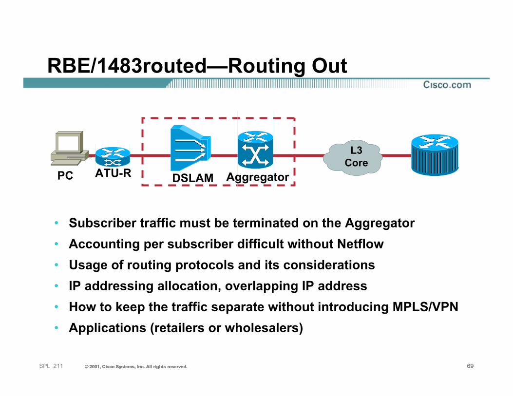
RBE/1483routed—Routing Out
• Subscriber traffic must be terminated on the Aggregator• Accounting per subscriber difficult without Netflow• Usage of routing protocols and its considerations• IP addressing allocation, overlapping IP address• How to keep the traffic separate without introducing MPLS/VPN• Applications (retailers or wholesalers)
PC
L3Core
ATU-R DSLAM Aggregator
© 2001, Cisco Systems, Inc. All rights reserved. 70© 2001, Cisco Systems, Inc. All rights reserved. 70© 2001, Cisco Systems, Inc. All rights reserved. 70SPL_211
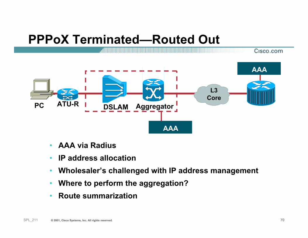
PPPoX Terminated—Routed Out
• AAA via Radius• IP address allocation• Wholesaler’s challenged with IP address management• Where to perform the aggregation?• Route summarization
PC
L3Core
ATU-R DSLAM Aggregator
AAA
AAA
© 2001, Cisco Systems, Inc. All rights reserved. 71© 2001, Cisco Systems, Inc. All rights reserved. 71© 2001, Cisco Systems, Inc. All rights reserved. 71SPL_211
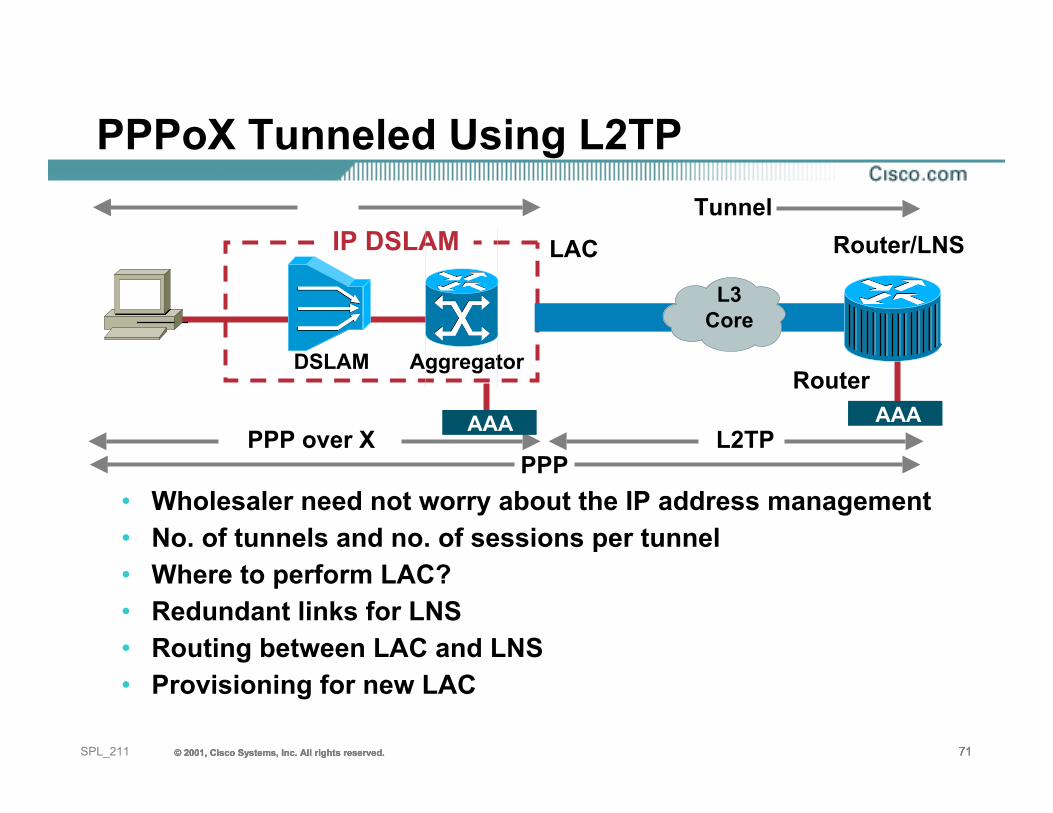
PPPoX Tunneled Using L2TP
• Wholesaler need not worry about the IP address management• No. of tunnels and no. of sessions per tunnel• Where to perform LAC?• Redundant links for LNS• Routing between LAC and LNS• Provisioning for new LAC
PPPPPP over X
Tunnel
Router
L3Core
Router/LNSLAC
DSLAM Aggregator
IP DSLAM
AAA AAAL2TP
© 2001, Cisco Systems, Inc. All rights reserved. 72© 2001, Cisco Systems, Inc. All rights reserved. 72© 2001, Cisco Systems, Inc. All rights reserved. 72SPL_211
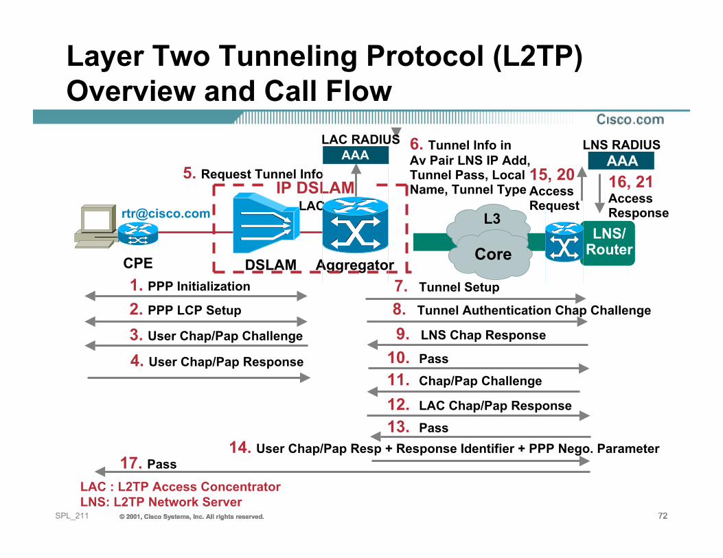
DSLAM AggregatorCPE
LAC
AAA
LNS/Router
1. PPP Initialization
2. PPP LCP Setup
3. User Chap/Pap Challenge
5. Request Tunnel Info
6. Tunnel Info inAv Pair LNS IP Add,Tunnel Pass, LocalName, Tunnel Type
8. Tunnel Authentication Chap Challenge
9. LNS Chap Response
11. Chap/Pap Challenge
12. LAC Chap/Pap Response
14. User Chap/Pap Resp + Response Identifier + PPP Nego. Parameter
15, 20AccessRequest
16, 21AccessResponse
17. Pass
AAALAC RADIUS LNS RADIUS
LAC : L2TP Access ConcentratorLNS: L2TP Network Server
4. User Chap/Pap Response
7. Tunnel Setup
13. Pass
10. Pass
IP DSLAM
L3
Core
Layer Two Tunneling Protocol (L2TP)Overview and Call Flow
© 2001, Cisco Systems, Inc. All rights reserved. 73© 2001, Cisco Systems, Inc. All rights reserved. 73© 2001, Cisco Systems, Inc. All rights reserved. 73SPL_211
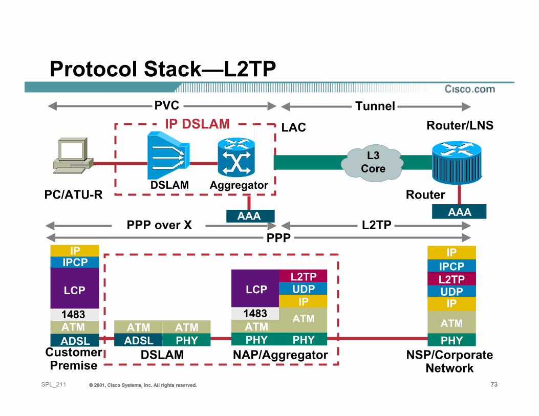
Protocol Stack—L2TP
NSP/CorporateNetwork
NAP/AggregatorCustomerPremise
PPPPPP over X L2TP
PVC Tunnel
PC/ATU-R
DSLAM
LCP
1483ATMPHY
IP
PHY
ATM
L2TPUDP
Router
L3Core
ATMADSL
ATMPHY PHY
ATM
IP
IP
IPCPL2TPUDPLCP
1483ATMADSL
IPCPIP
Router/LNSLAC
DSLAM Aggregator
IP DSLAM
AAA AAA
© 2001, Cisco Systems, Inc. All rights reserved. 74© 2001, Cisco Systems, Inc. All rights reserved. 74© 2001, Cisco Systems, Inc. All rights reserved. 74SPL_211
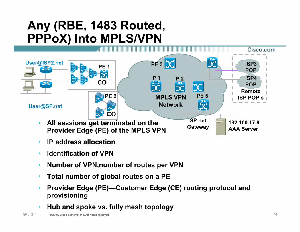
Any (RBE, 1483 Routed,PPPoX) Into MPLS/VPN
• All sessions get terminated on the Provider Edge (PE) of the MPLS VPN
• IP address allocation• Identification of VPN• Number of VPN,number of routes per VPN• Total number of global routes on a PE• Provider Edge (PE)—Customer Edge (CE) routing protocol and
provisioning• Hub and spoke vs. fully mesh topology
CO
CO
PE 1
PE 2 MPLS VPNNetwork
RemoteISP POP’s
P 1 P 2
SP.netGateway
PE 5
192.100.17.8AAA Server
ISP4POP
ISP3POP
PE 3
© 2001, Cisco Systems, Inc. All rights reserved. 75© 2001, Cisco Systems, Inc. All rights reserved. 75© 2001, Cisco Systems, Inc. All rights reserved. 75SPL_211
Agenda
• Digital Subscriber Line Technologies• Subscriber Connection Models• Reaching the Services• Case Studies• Summary
© 2001, Cisco Systems, Inc. All rights reserved. 76© 2001, Cisco Systems, Inc. All rights reserved. 76© 2001, Cisco Systems, Inc. All rights reserved. 76SPL_211
Case Study 1
• Customer is a Network Access Provider (NAP), regulated side of an ILEC
• NAP can not handle any L3 info• Wants to offer services to 500,000 residential
subscribers at 128 Kbps upstream and 784 Kbps downstream
• Maximum concentration at each CO is 2000
© 2001, Cisco Systems, Inc. All rights reserved. 77© 2001, Cisco Systems, Inc. All rights reserved. 77© 2001, Cisco Systems, Inc. All rights reserved. 77SPL_211
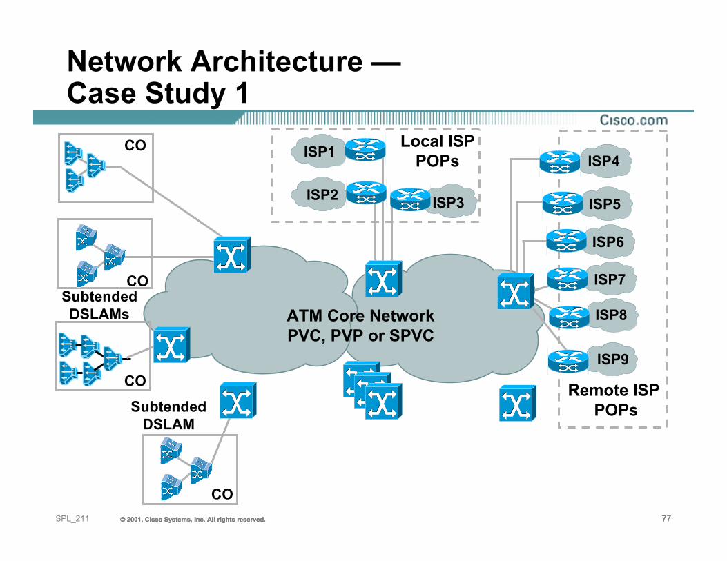
Network Architecture —Case Study 1
ATM Core NetworkPVC, PVP or SPVC
ISP7
ISP6
ISP5
ISP9
ISP8
ISP4
Remote ISP POPs
ISP2 ISP3
Local ISPPOPs
CO
CO
SubtendedDSLAMs
SubtendedDSLAM
CO
CO
ISP1
© 2001, Cisco Systems, Inc. All rights reserved. 78© 2001, Cisco Systems, Inc. All rights reserved. 78© 2001, Cisco Systems, Inc. All rights reserved. 78SPL_211
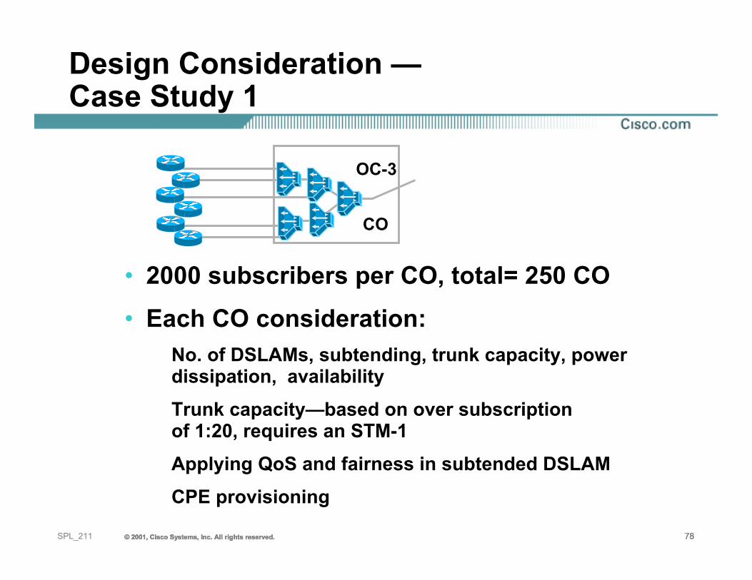
Design Consideration —Case Study 1
• 2000 subscribers per CO, total= 250 CO• Each CO consideration:
No. of DSLAMs, subtending, trunk capacity, power dissipation, availabilityTrunk capacity—based on over subscription of 1:20, requires an STM-1Applying QoS and fairness in subtended DSLAMCPE provisioning
CO
OC-3
© 2001, Cisco Systems, Inc. All rights reserved. 79© 2001, Cisco Systems, Inc. All rights reserved. 79© 2001, Cisco Systems, Inc. All rights reserved. 79SPL_211
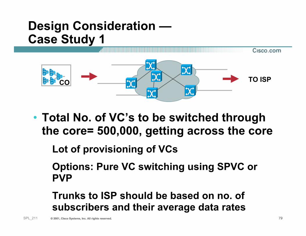
Design Consideration —Case Study 1
• Total No. of VC’s to be switched through the core= 500,000, getting across the core
Lot of provisioning of VCsOptions: Pure VC switching using SPVC or PVPTrunks to ISP should be based on no. of subscribers and their average data rates
CO TO ISP
© 2001, Cisco Systems, Inc. All rights reserved. 80© 2001, Cisco Systems, Inc. All rights reserved. 80© 2001, Cisco Systems, Inc. All rights reserved. 80SPL_211
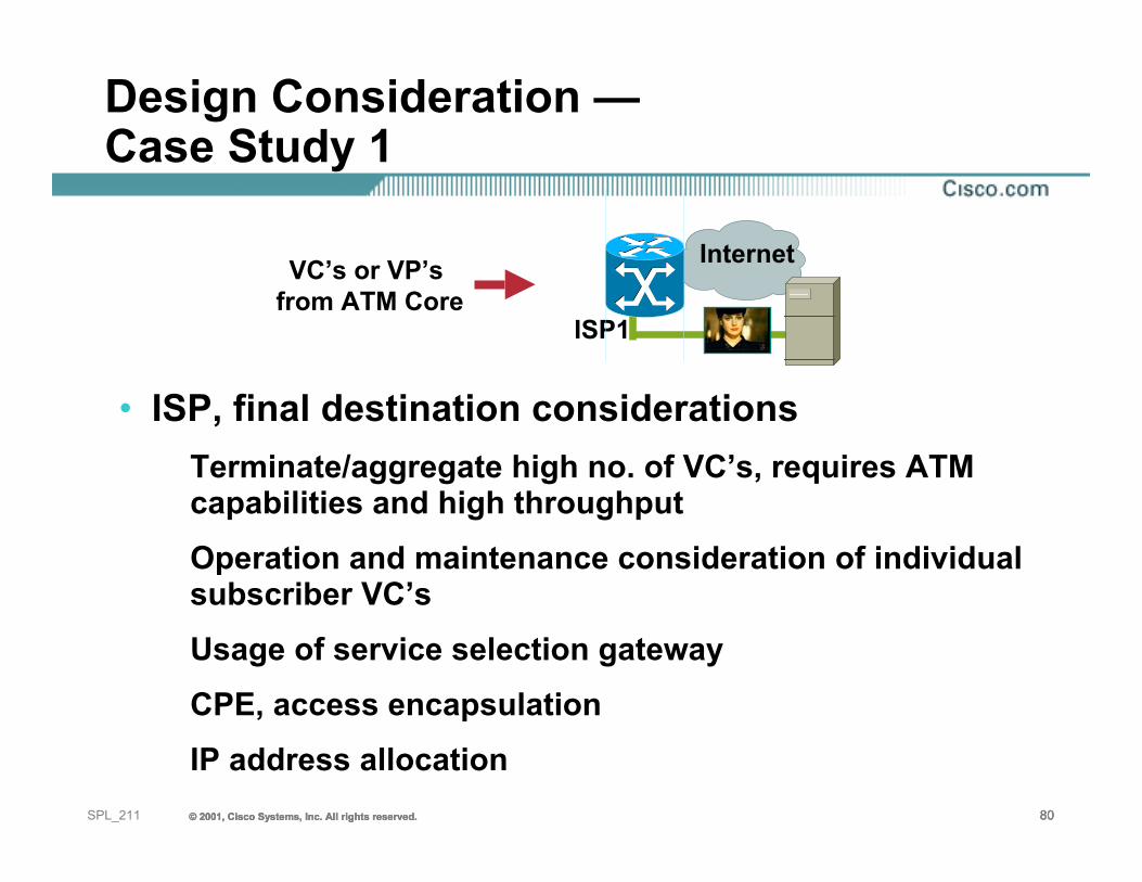
Design Consideration —Case Study 1
• ISP, final destination considerationsTerminate/aggregate high no. of VC’s, requires ATM capabilities and high throughput Operation and maintenance consideration of individual subscriber VC’sUsage of service selection gatewayCPE, access encapsulationIP address allocation
VC’s or VP’s from ATM Core
Internet
ISP1
© 2001, Cisco Systems, Inc. All rights reserved. 81© 2001, Cisco Systems, Inc. All rights reserved. 81© 2001, Cisco Systems, Inc. All rights reserved. 81SPL_211
Case Study 2
• Customer is from an unregulated side of an ILEC • Wants to offer local ISP services as well as
wholesale residential services to 100 other regional ISP’s
• Customer also wants to offer business VPNs to corporations
• Number of subscriber and concentration per CO remains unchanged from the previous case study
© 2001, Cisco Systems, Inc. All rights reserved. 82© 2001, Cisco Systems, Inc. All rights reserved. 82© 2001, Cisco Systems, Inc. All rights reserved. 82SPL_211
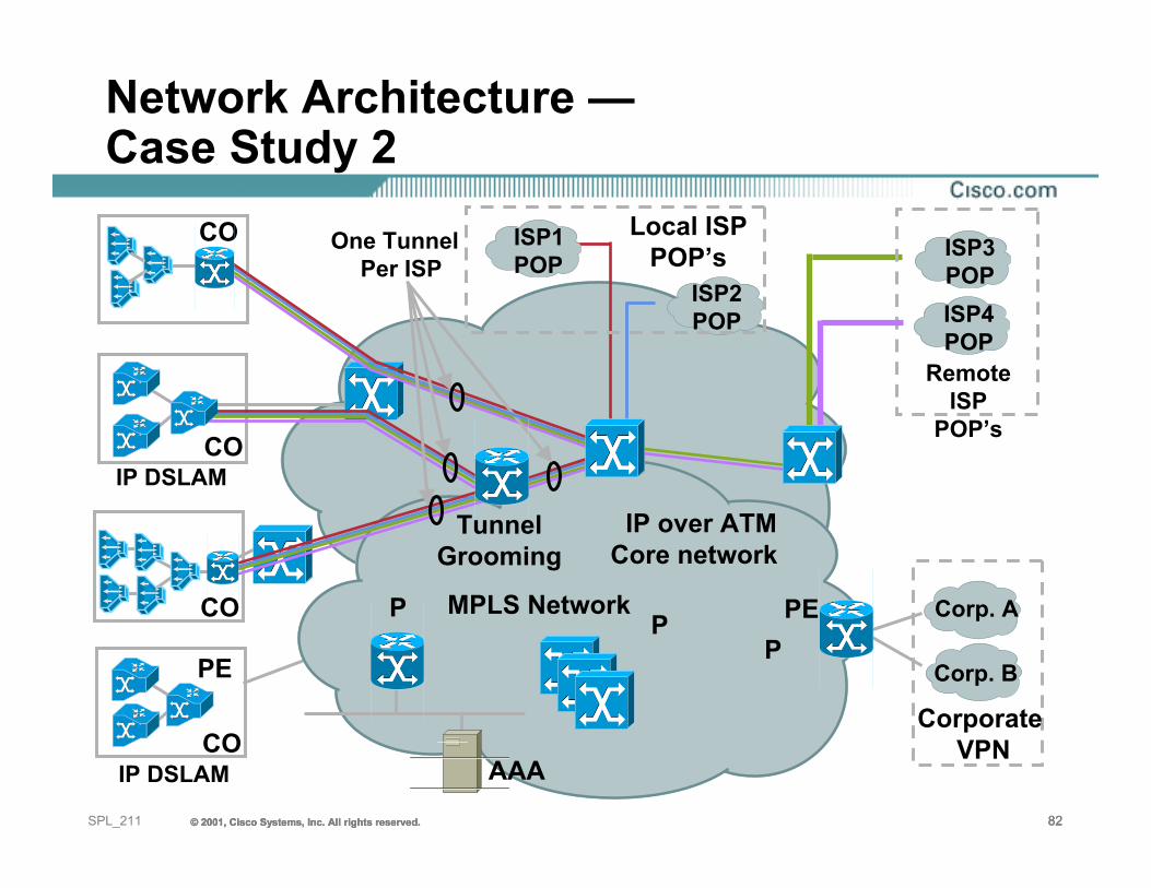
Network Architecture —Case Study 2
IP over ATMCore network
ISP4POP
ISP3POP
Remote ISP
POP’s
ISP1POP
ISP2POP
Local ISPPOP’s
CO
CO
IP DSLAMCO
AAA
One TunnelPer ISP
MPLS Network
IP DSLAMCO
Corp. B
Corp. A
Corporate VPN
PE
PEP PP
TunnelGrooming
© 2001, Cisco Systems, Inc. All rights reserved. 83© 2001, Cisco Systems, Inc. All rights reserved. 83© 2001, Cisco Systems, Inc. All rights reserved. 83SPL_211
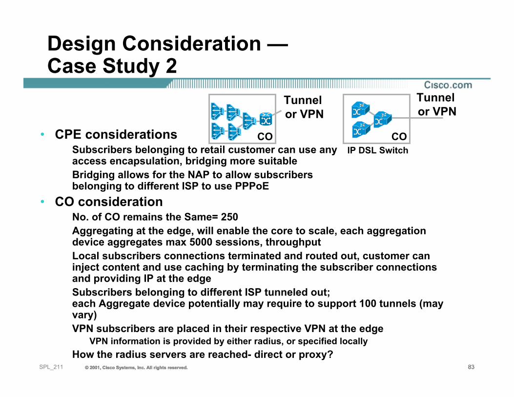
Design Consideration —Case Study 2
• CPE considerationsSubscribers belonging to retail customer can use anyaccess encapsulation, bridging more suitableBridging allows for the NAP to allow subscribers belonging to different ISP to use PPPoE
• CO considerationNo. of CO remains the Same= 250Aggregating at the edge, will enable the core to scale, each aggregation device aggregates max 5000 sessions, throughputLocal subscribers connections terminated and routed out, customer can inject content and use caching by terminating the subscriber connections and providing IP at the edgeSubscribers belonging to different ISP tunneled out; each Aggregate device potentially may require to support 100 tunnels (may vary) VPN subscribers are placed in their respective VPN at the edge
VPN information is provided by either radius, or specified locallyHow the radius servers are reached- direct or proxy?
COIP DSL Switch
CO
Tunnel or VPN
Tunnel or VPN
© 2001, Cisco Systems, Inc. All rights reserved. 84© 2001, Cisco Systems, Inc. All rights reserved. 84© 2001, Cisco Systems, Inc. All rights reserved. 84SPL_211
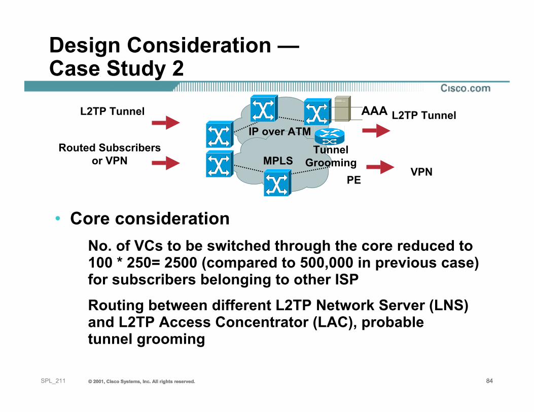
Design Consideration —Case Study 2
• Core considerationNo. of VCs to be switched through the core reduced to 100 * 250= 2500 (compared to 500,000 in previous case) for subscribers belonging to other ISPRouting between different L2TP Network Server (LNS) and L2TP Access Concentrator (LAC), probable tunnel grooming
MPLS
IP over ATM
L2TP Tunnel
Routed Subscribersor VPN
L2TP Tunnel
VPN
AAA
PE
Tunnel Grooming
© 2001, Cisco Systems, Inc. All rights reserved. 85© 2001, Cisco Systems, Inc. All rights reserved. 85© 2001, Cisco Systems, Inc. All rights reserved. 85SPL_211
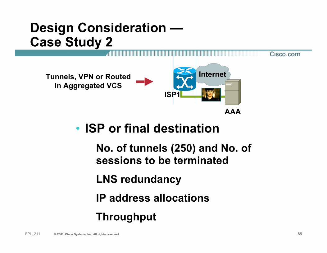
Design Consideration —Case Study 2
• ISP or final destinationNo. of tunnels (250) and No. of sessions to be terminatedLNS redundancyIP address allocationsThroughput
Tunnels, VPN or Routedin Aggregated VCS
AAA
Internet
ISP1
© 2001, Cisco Systems, Inc. All rights reserved. 86© 2001, Cisco Systems, Inc. All rights reserved. 86© 2001, Cisco Systems, Inc. All rights reserved. 86SPL_211
Agenda
• Digital Subscriber Line Technologies• Subscriber Connection Models• Reaching the Services• Case Studies• Summary , questions and answers
© 2001, Cisco Systems, Inc. All rights reserved. 87© 2001, Cisco Systems, Inc. All rights reserved. 87© 2001, Cisco Systems, Inc. All rights reserved. 87SPL_211
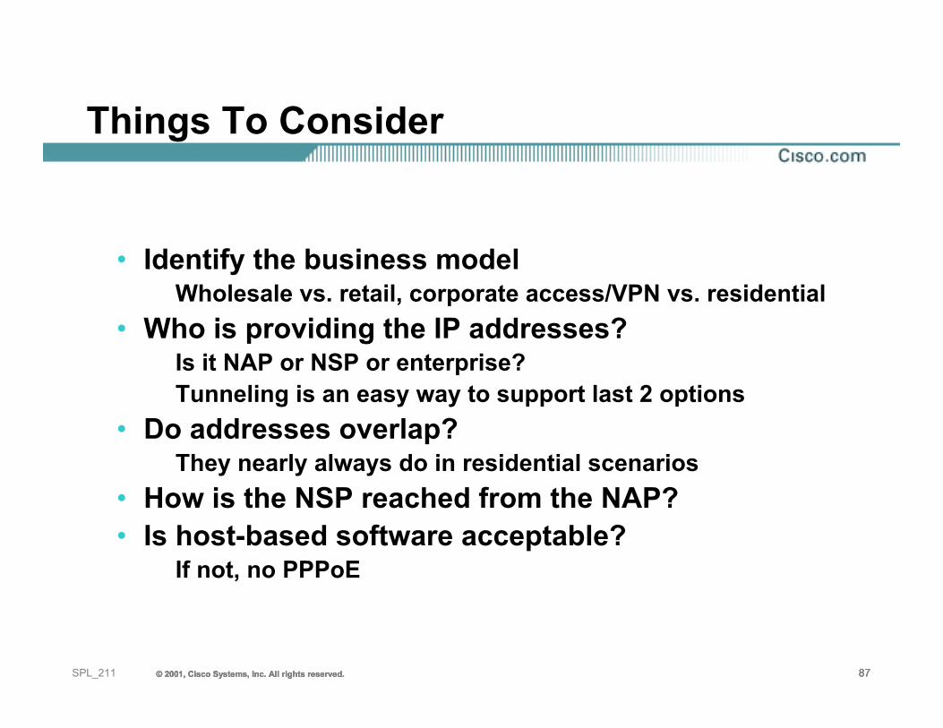
Things To Consider
• Identify the business modelWholesale vs. retail, corporate access/VPN vs. residential
• Who is providing the IP addresses?Is it NAP or NSP or enterprise?Tunneling is an easy way to support last 2 options
• Do addresses overlap?They nearly always do in residential scenarios
• How is the NSP reached from the NAP?• Is host-based software acceptable?
If not, no PPPoE
© 2001, Cisco Systems, Inc. All rights reserved. 88© 2001, Cisco Systems, Inc. All rights reserved. 88© 2001, Cisco Systems, Inc. All rights reserved. 88SPL_211
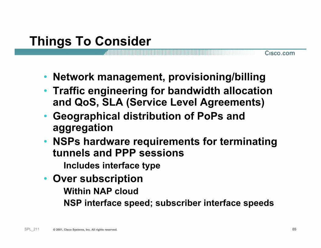
Things To Consider
• Network management, provisioning/billing• Traffic engineering for bandwidth allocation
and QoS, SLA (Service Level Agreements)• Geographical distribution of PoPs and
aggregation• NSPs hardware requirements for terminating
tunnels and PPP sessionsIncludes interface type
• Over subscriptionWithin NAP cloudNSP interface speed; subscriber interface speeds
© 2001, Cisco Systems, Inc. All rights reserved. 89© 2001, Cisco Systems, Inc. All rights reserved. 89© 2001, Cisco Systems, Inc. All rights reserved. 89SPL_211
Recommended Reading
• SPL 210—Deploying Next Gen DSL Network• White Papers on Various Access Architectures
available:http://www.cisco.com/warp/customer/794/pppoe_arch.htmlhthttp://www.cisco.com/warp/customer/794/pppoa_arch.htmlhthttp://www.cisco.com/warp/customer/794/routed_bridged_encap.htmlhttp://www.cisco.com/warp/customer/794/rfc_brdg_arch.html
© 2001, Cisco Systems, Inc. All rights reserved. 90© 2001, Cisco Systems, Inc. All rights reserved. 90© 2001, Cisco Systems, Inc. All rights reserved. 90SPL_211
Questions, Comments?
TMTM
91SPL_211 © 2001, Cisco Systems, Inc. All rights reserved.© 2001, Cisco Systems, Inc. All rights reserved.© 2001, Cisco Systems, Inc. All rights reserved.
Design Principles forDSL-Based Access Solutions
Session SPL-211
92SPL_211 © 2001, Cisco Systems, Inc. All rights reserved.© 2001, Cisco Systems, Inc. All rights reserved.© 2001, Cisco Systems, Inc. All rights reserved.
Please Complete Your Evaluation Form
Session SPL-211
93SPL_211 © 2001, Cisco Systems, Inc. All rights reserved.