Embed Size (px)
Citation preview

Wingspan....................................65.25.in.(1657mm)Wing.Area........................729.5.sq.in.(47.06.sq.dm)
Assembly mAnuAl
Spitfire 60 ARF
Length...........................................55.5.in.(1410mm)Weight................................8.0–9.0.lb.(3.6kg–4.0kg)
Specifications

2
Table of ContentsContents.of.Kit. . . . . . . . . . . . . . . . . . . . . . . . . . . . . . . . . . . . . . . . . . . . . . . . . . . . . . . . . . . . . . . . . . . . .3Radio.and.Power.Systems.Requirements.. . . . . . . . . . . . . . . . . . . . . . . . . . . . . . . . . . . . . . . . . . . . . . . .3UltraCote®.Covering.Colors . . . . . . . . . . . . . . . . . . . . . . . . . . . . . . . . . . . . . . . . . . . . . . . . . . . . . . . . . .4Field.Equipment.Required. . . . . . . . . . . . . . . . . . . . . . . . . . . . . . . . . . . . . . . . . . . . . . . . . . . . . . . . . . . .4Optional.Field.Equipment.. . . . . . . . . . . . . . . . . . . . . . . . . . . . . . . . . . . . . . . . . . . . . . . . . . . . . . . . . . . .4Required.Tools.and.Adhesives. . . . . . . . . . . . . . . . . . . . . . . . . . . . . . . . . . . . . . . . . . . . . . . . . . . . . . . . .4Limited.Warranty.Period . . . . . . . . . . . . . . . . . . . . . . . . . . . . . . . . . . . . . . . . . . . . . . . . . . . . . . . . . . . . .5Limited.Warranty.&.Limits.of.Liability. . . . . . . . . . . . . . . . . . . . . . . . . . . . . . . . . . . . . . . . . . . . . . . . . . .5Safety.Precautions. . . . . . . . . . . . . . . . . . . . . . . . . . . . . . . . . . . . . . . . . . . . . . . . . . . . . . . . . . . . . . . . . .5Questions,.Assistance,.and.Repairs. . . . . . . . . . . . . . . . . . . . . . . . . . . . . . . . . . . . . . . . . . . . . . . . . . . . .5Questions.or.Assistance.. . . . . . . . . . . . . . . . . . . . . . . . . . . . . . . . . . . . . . . . . . . . . . . . . . . . . . . . . . . . .5Inspection.or.Repairs. . . . . . . . . . . . . . . . . . . . . . . . . . . . . . . . . . . . . . . . . . . . . . . . . . . . . . . . . . . . . . . .6Warranty.Inspection.and.Repairs. . . . . . . . . . . . . . . . . . . . . . . . . . . . . . . . . . . . . . . . . . . . . . . . . . . . . . .6Non-Warranty.Repairs. . . . . . . . . . . . . . . . . . . . . . . . . . . . . . . . . . . . . . . . . . . . . . . . . . . . . . . . . . . . . . .6Safety,.Precautions,.and.Warnings.. . . . . . . . . . . . . . . . . . . . . . . . . . . . . . . . . . . . . . . . . . . . . . . . . . . . .7Before.Starting.Assembly.. . . . . . . . . . . . . . . . . . . . . . . . . . . . . . . . . . . . . . . . . . . . . . . . . . . . . . . . . . . .7Using.the.Manual.. . . . . . . . . . . . . . . . . . . . . . . . . . . . . . . . . . . . . . . . . . . . . . . . . . . . . . . . . . . . . . . . . .7Section.1:.Aileron.Installation . . . . . . . . . . . . . . . . . . . . . . . . . . . . . . . . . . . . . . . . . . . . . . . . . . . . . . . . .8Section.2:.Joining.the.Wing.Panels. . . . . . . . . . . . . . . . . . . . . . . . . . . . . . . . . . . . . . . . . . . . . . . . . . . .14Section.3:.Retract.Installation . . . . . . . . . . . . . . . . . . . . . . . . . . . . . . . . . . . . . . . . . . . . . . . . . . . . . . . .18Section.4:.Flap.Installation . . . . . . . . . . . . . . . . . . . . . . . . . . . . . . . . . . . . . . . . . . . . . . . . . . . . . . . . . .21Section.5:.Engine.Installation . . . . . . . . . . . . . . . . . . . . . . . . . . . . . . . . . . . . . . . . . . . . . . . . . . . . . . . .24Section.6:.Cowling.Installation . . . . . . . . . . . . . . . . . . . . . . . . . . . . . . . . . . . . . . . . . . . . . . . . . . . . . . .27Section.7:.Rudder.Installation . . . . . . . . . . . . . . . . . . . . . . . . . . . . . . . . . . . . . . . . . . . . . . . . . . . . . . . .29Section.8:.Stabilizer.Installation.. . . . . . . . . . . . . . . . . . . . . . . . . . . . . . . . . . . . . . . . . . . . . . . . . . . . . .32Section.9:.Final.Assembly. . . . . . . . . . . . . . . . . . . . . . . . . . . . . . . . . . . . . . . . . . . . . . . . . . . . . . . . . . .37Adjusting.the.Engine. . . . . . . . . . . . . . . . . . . . . . . . . . . . . . . . . . . . . . . . . . . . . . . . . . . . . . . . . . . . . . .40Control.Throws . . . . . . . . . . . . . . . . . . . . . . . . . . . . . . . . . . . . . . . . . . . . . . . . . . . . . . . . . . . . . . . . . . .40Recommended.Center.of.Gravity.(CG). . . . . . . . . . . . . . . . . . . . . . . . . . . . . . . . . . . . . . . . . . . . . . . . . .41Pre-Flight.. . . . . . . . . . . . . . . . . . . . . . . . . . . . . . . . . . . . . . . . . . . . . . . . . . . . . . . . . . . . . . . . . . . . . . .41Range.Test.Your.Radio. . . . . . . . . . . . . . . . . . . . . . . . . . . . . . . . . . . . . . . . . . . . . . . . . . . . . . . . . . . . . .412006.Official.AMA.National.Model.Aircraft.Safety.Code . . . . . . . . . . . . . . . . . . . . . . . . . . . . . . . . . . . .42

3
Contents of Kit
Radio and Power Systems Requirements•.5-.to.6-channel.radio.system.(minimum).w/receiver•..537.Standard.Servo.(JRPS537).(5).or.equivalent.for.rudder.(1),.elevator.(1),.ailerons.(2),.throttle.(1).
(Plus.1.servo.required.when.using.the.flap.option).(Plus.1.JRPS791.or.equivalent.for.retracts.).(4.required.when.building.the.electric.version)
•.12".Servo.Lead.Extension.(JRPA098).(2)•.6”.Y-Harness.(JSP98020)
Recommended JR® or JR SPORT™ Systems•.XP9303•.XP7202•.XP6102•.XS600
Recommended Power Systems•..60–.61.2-stroke•..91–1.00.4-stroke•.Power.60.Brushless.Outrunner
A
BD
C
JR XP6102
JR XP9303
Evolution .61NTEVOE0610
Saito 1.00 AACSAIE100
E-Flite™ Power 60 Brushless Outrunner
Motor,400KV EFLM4060A
JR XP7202
Replacement PartsA.. HAN4251. FuselageB.. HAN4252. .Wing.Set,.Ailerons,.Joiners.
and.RetractsC.. HAN4253. Tail.SetD.. HAN4254. Canopy.w/Painted.FrameE.. HAN4256. Painted.Fiberglass.CowlF.. HAN4261. .Cockpit.Detail.Set.and.
Exhaust.SetG.. HAN4257. .Molded.Wheel.Well,.Strut.
Covers.and.RadiatorsH.. HAN4258. Tail.Wheel.Assembly
Items not shownHAN4259. Decal.SetHAN4260. Pushrod.SetHAN4262. Retracts
E
G HF G
B

4
UltraCote® Covering ColorsCocoa. HANU876. Olive.Drab. HANU904Light.Grey. HANU882
Field Equipment Required•.Propeller.. •.4-Cycle.Super.Plug.(HAN3011)•.Long.Reach.Glow.Plug.Wrench.(HAN2510). •.Metered.Glow.Driver.w/Ni-Cd.&.Charger.(HAN7101)•.2-Cycle.Sport.Plug.(HAN3001). •.Fuel•.2-Cycle.Super.Plug.(HAN3006). •.Manual.Fuel.Pump.(HAN118)
Optional Field Equipment•.12V.7Ah.Sealed.Battery.(HAN102). •.PowerPro™.12V.Starter.(HAN161)
Required Tools and Adhesives
Tools•.Canopy.scissors. •.Drill•.Square. . •.Flat.blade.screwdriver•.Foam:.1/4".(6mm). •.Hobby.knife•.Side.cutters. •.Phillips.screwdriver.(large)•.Phillips.screwdriver.(small). •.Pliers•.Ruler. . •.Sandpaper•.Hex.wrench:.9/64",.3/16". •.Socket.wrench:.11/32"•.Drill.bit:.1/16".(1.5mm),.5/64".(2mm),.3/32".(2.5mm),.1/8".(3mm),.9/64".(3.5mm),.5/32".(4mm),.1/4".(6mm)
Adhesives•.6-minute.epoxy. •.30-minute.epoxy•.Thin.CA.(cyanoacrylate).glue. •.Medium.CA.(cyanoacrylate).glue•.CA.remover/debonder. •.Pacer.Z-42.Threadlock•.Zap-A-Dap-A-Goo. •.Hinge.glue•.Canopy.glue.(Formula.560). •.Masking.tape.(3M.blue.recommended)
Other Required Items•.Epoxy.brushes. •.Felt-tipped.pen.or.pencil•.File. . •.Measuring.device.(e.g..ruler,.tape.measure)•.Mixing.sticks.for.epoxy. •.Paper.towels•.Petroleum.jelly. •.Rubbing.alcohol•.Sanding.bar. •.Sandpaper.(medium)•.String. . •.T-pins•.Wax.paper. •.Rotary.tool.w/sanding.drums

5
Limited Warranty PeriodHorizon.Hobby,.Inc..guarantees.this.product.to.be.free.from.defects.in.both.material.and.workmanship.at.the.date.of.purchase.
Limited Warranty & Limits of LiabilityPursuant.to.this.Limited.Warranty,.Horizon.Hobby,.Inc..will,.at.its.option,.(i).repair.or.(ii).replace,.any.product.determined.by.Horizon.Hobby,.Inc..to.be.defective..In.the.event.of.a.defect,.these.are.your.exclusive.remedies.This.warranty.does.not.cover.cosmetic.damage.or.damage.due.to.acts.of.God,.accident,.misuse,.abuse,.negligence,.commercial.use,.or.modification.of.or.to.any.part.of.the.product..This.warranty.does.not.cover.damage.due.to.improper.installation,.operation,.maintenance,.or.attempted.repair.by.anyone.other.than.an.authorized.Horizon.Hobby,.Inc..service.center..This.warranty.is.limited.to.the.original.purchaser.and.is.not.transferable..In.no.case.shall.Horizon.Hobby’s.liability.exceed.the.original.cost.of.the.purchased.product.and.will.not.cover.consequential,.incidental.or.collateral.damage..Horizon.Hobby,.Inc..reserves.the.right.to.inspect.any.and.all.equipment.involved.in.a.warranty.claim..Repair.or.replacement.decisions.are.at.the.sole.discretion.of.Horizon.Hobby,.Inc..Further,.Horizon.Hobby.reserves.the.right.to.change.or.modify.this.warranty.without.notice.REPAIR.OR.REPLACEMENT.AS.PROVIDED.UNDER.THIS.WARRANTY.IS.THE.EXCLUSIVE.REMEDY.OF.THE.CONSUMER..HORIZON.HOBBY,.INC..SHALL.NOT.BE.LIABLE.FOR.ANY.INCIDENTAL.OR.CONSEQUENTIAL.DAMAGES.As.Horizon.Hobby,.Inc..has.no.control.over.use,.setup,.final.assembly,.modification.or.misuse,.no.liability.shall.be.assumed.nor.accepted.for.any.resulting.damage.or.injury..By.the.act.of.use,.setup.or.assembly,.the.user.accepts.all.resulting.liability.If.you.as.the.purchaser.or.user.are.not.prepared.to.accept.the.liability.associated.with.the.use.of.this.product,.you.are.advised.to.return.this.product.immediately.in.new.and.unused.condition.to.the.place.of.purchase.
Safety PrecautionsThis.is.a.sophisticated.hobby.product.and.not.a.toy..It.must.be.operated.with.caution.and.common.sense.and.requires.some.basic.mechanical.ability..Failure.to.operate.this.product.in.a.safe.and.responsible.manner.could.result.in.injury.or.damage.to.the.product.or.other.property..This.product.is.not.intended.for.use.by.children.without.direct.adult.supervision.The.product.manual.contains.instructions.for.safety,.operation.and.maintenance..It.is.essential.to.read.and.follow.all.the.instructions.and.warnings.in.the.manual,.prior.to.assembly,.setup.or.use,.in.order.to.operate.correctly.and.avoid.damage.or.injury.
Questions, Assistance, and RepairsYour.local.hobby.store.and/or.place.of.purchase.cannot.provide.warranty.support.or.repair..Once.assembly,.setup.or.use.of.the.product.has.been.started,.you.must.contact.Horizon.Hobby,.Inc..directly..This.will.enable.Horizon.to.better.answer.your.questions.and.service.you.in.the.event.that.you.may.need.any.assistance.
Questions or AssistanceFor.questions.or.assistance,[email protected],.or.call.877.504.0233.toll.free.to.speak.to.a.service.technician.

6
Inspection or RepairsIf.your.product.needs.to.be.inspected.or.repaired,.please.call.for.a.Return.Merchandise.Authorization.(RMA)..Pack.the.product.securely.using.a.shipping.carton..Please.note.that.original.boxes.may.be.included,.but.are.not.designed.to.withstand.the.rigors.of.shipping.without.additional.protection..Ship.via.a.carrier.that.provides.tracking.and.insurance.for.lost.or.damaged.parcels,.as.Horizon.Hobby,.Inc..is.not.responsible.for.merchandise.until.it.arrives.and.is.accepted.at.our.facility..Include.your.complete.name,.address,.phone.number.where.you.can.be.reached.during.business.days,.RMA.number,.and.a.brief.summary.of.the.problem..Be.sure.your.name,.address,.and.RMA.number.are.clearly.written.on.the.shipping.carton.
Warranty Inspection and RepairsTo.receive.warranty.service,.you.must.include.your.original.sales.receipt.verifying.the.proof-of-purchase.date..Providing.warranty.conditions.have.been.met,.your.product.will.be.repaired.or.replaced.free.of.charge..Repair.or.replacement.decisions.are.at.the.sole.discretion.of.Horizon.Hobby.
Non-Warranty RepairsShould.your.repair.not.be.covered.by.warranty.and.the.expense.exceeds.50%.of.the.retail.purchase.cost,.you.will.be.provided.with.an.estimate.advising.you.of.your.options..You.will.be.billed.for.any.return.freight.for.non-warranty.repairs..Please.advise.us.of.your.preferred.method.of.payment..Horizon.Hobby.accepts.money.orders.and.cashiers.checks,.as.well.as.Visa,.MasterCard,.American.Express,.and.Discover.cards..If.you.choose.to.pay.by.credit.card,.please.include.your.credit.card.number.and.expiration.date..Any.repair.left.unpaid.or.unclaimed.after.90.days.will.be.considered.abandoned.and.will.be.disposed.of.accordingly.Electronics.and.engines.requiring.inspection.or.repair.should.be.shipped.to.the.following.address.(freight.prepaid):
Horizon.Service.Center4105.Fieldstone.Road
Champaign,.Illinois.61822All.other.products.requiring.inspection.or.repair.should.be.shipped.to.the.following.address.(freight.prepaid):
Horizon.Product.Support4105.Fieldstone.Road
Champaign,.Illinois.61822

7
Safety, Precautions, and WarningsThis.model.is.controlled.by.a.radio.signal.that.is.subject.to.interference.from.many.sources.outside.your.control..This.interference.can.cause.momentary.loss.of.control.so.it.is.advisable.to.always.keep.a.safe.distance.in.all.directions.around.your.model,.as.this.margin.will.help.to.avoid.collisions.or.injury.•.Always.operate.your.model.in.an.open.area.away.from.cars,.traffic,.or.people.•.Avoid.operating.your.model.in.the.street.where.injury.or.damage.can.occur.•.Never.operate.the.model.out.into.the.street.or.populated.areas.for.any.reason.•.Never.operate.your.model.with.low.transmitter.batteries.•..Carefully.follow.the.directions.and.warnings.for.this.and.any.optional.support.equipment.(chargers,.rechargeable.
battery.packs,.etc.).that.you.use.•.Keep.all.chemicals,.small.parts.and.anything.electrical.out.of.the.reach.of.children.•..Moisture.causes.damage.to.electronics..Avoid.water.exposure.to.all.equipment.not.specifically.designed.and.protected.
for.this.purpose.
Before Starting AssemblyBefore.beginning.the.assembly.of.the.Spitfire.60,.remove.each.part.from.its.bag.for.inspection..Closely.inspect.the.fuselage,.wing.panels,.rudder,.and.stabilizer.for.damage..If.you.find.any.damaged.or.missing.parts,.contact.the.place.of.purchase.If.you.find.any.wrinkles.in.the.covering,.use.a.heat.gun.or.sealing.iron.to.remove.them..Use.caution.while.working.around.areas.where.the.colors.overlap.to.prevent.separating.the.colors.
Using the Manual
This.manual.is.divided.into.sections.to.help.make.assembly.easier.to.understand,.and.to.provide.breaks.between.each.major.section..In.addition,.check.boxes.have.been.placed.next.to.each.step.to.keep.track.of.each.step.completed..Steps.with.a.single.box.().are.performed.once,.while.steps.with.two.boxes.(.).indicate.that.the.step.will.require.repeating,.such.as.for.a.right.or.left.wing.panel,.two.servos,.etc..Remember.to.take.your.time.and.follow.the.directions.
HAN100 – Heat Gun
HAN150 – Covering Glove
HAN101 – Sealing Iron
HAN141 – Sealing Iron Sock
8
Required Parts•.Wing.(left.and.right). •.Aileron.(left.and.right)•.Nylon.clevis.(2). •.Nylon.wire.keeper.(2)•.CA.hinges.(6)•#2.x.3/8".sheet.metal.screw.(8)•.2-56.x.1".machine.screw.(6)•.Nylon.control.horn.w/backplate.(2)•.Threaded.pushrod,.6".(150mm).(2)•.Servo.mounting.block,..3/4".x.3/4".x.3/8".
(18mm.x.18mm.x.10mm).(4)•.Heat.shrink.tubing
Required Tools and Adhesives•.Thin.CA. •.T-pins•.6-minute.epoxy. •.Felt-tipped.pen•.Drill. •.Side.cutters•.Low-tack.tape. •.Ruler•.Phillips.screwdriver. •.Pliers•.12".servo.extension.(2)•.Drill.bit:.1/16".(1.5mm),.3/32".(2.5mm)
..Step 1Remove.the.aileron.from.the.wing..Place.a.T-pin.in.the.center.of.each.hinge.
..Step 2Place.the.hinges.in.the.precut.slots.in.the.aileron..The..T-pin.will.rest.against.the.leading.edge.of.the.aileron..when.installed.correctly.
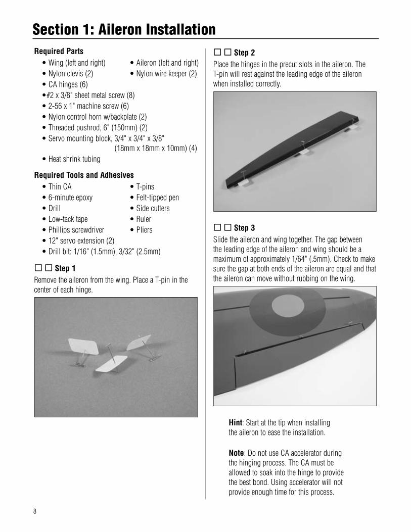
..Step 3Slide.the.aileron.and.wing.together..The.gap.between.the.leading.edge.of.the.aileron.and.wing.should.be.a.maximum.of.approximately.1/64".(.5mm)..Check.to.make.sure.the.gap.at.both.ends.of.the.aileron.are.equal.and.that.the.aileron.can.move.without.rubbing.on.the.wing.
Hint:.Start.at.the.tip.when.installing.the.aileron.to.ease.the.installation.
Note:.Do.not.use.CA.accelerator.during.the.hinging.process..The.CA.must.be.allowed.to.soak.into.the.hinge.to.provide.the.best.bond..Using.accelerator.will.not.provide.enough.time.for.this.process.
Section 1: Aileron Installation
9
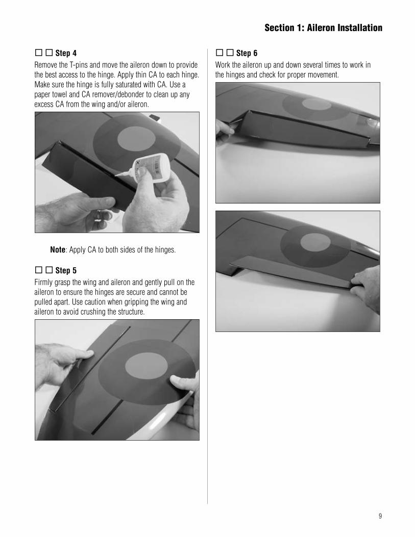
..Step 4Remove.the.T-pins.and.move.the.aileron.down.to.provide.the.best.access.to.the.hinge..Apply.thin.CA.to.each.hinge..Make.sure.the.hinge.is.fully.saturated.with.CA..Use.a.paper.towel.and.CA.remover/debonder.to.clean.up.any.excess.CA.from.the.wing.and/or.aileron.
Note:.Apply.CA.to.both.sides.of.the.hinges.
..Step 5Firmly.grasp.the.wing.and.aileron.and.gently.pull.on.the.aileron.to.ensure.the.hinges.are.secure.and.cannot.be.pulled.apart..Use.caution.when.gripping.the.wing.and.aileron.to.avoid.crushing.the.structure.
..Step 6Work.the.aileron.up.and.down.several.times.to.work.in..the.hinges.and.check.for.proper.movement.
Section 1: Aileron Installation

10
..Step 7Remove.the.aileron.hatch.from.the.wing..Remove.the.covering.from.the.slot.for.the.aileron.horn.
Note:.The.aileron.servo.is.mounted.directly.to.the.hatch.
Hint:.Use.a.ruler.as.a.straight.edge.to.make.sure.the.marks.for.the.servo.are.parallel.to.the.slot.for.the.servo.horn.
..Step 8Install.the.recommended.servo.hardware.(grommets.and.eyelets).supplied.with.the.servo..Temporarily.install.a.long.half.servo.arm.(JRPA212).onto.the.servo.and.position.the.servo.onto.the.hatch.so.the.servo.arm.is.centered.in.the.notch..Once.satisfied,.mark.the.location.for.the.servo.mounting.blocks.
..Step 9Locate.the.servo.mounting.blocks..Use.6-minute.epoxy.to.glue.the.blocks.to.the.hatch..Let.the.epoxy.fully.cure.before.proceeding.to.the.next.step.
..Step 10Place.the.aileron.servo.between.the.mounting.blocks.and.use.a.felt-tipped.pen.to.mark.the.location.of.the.four.servo.mounting.screws..Note.that.the.servo.must.not.touch.the.hatch.in.order.to.isolate.engine.vibration.
Note:.Before.mounting.the.servo,.it.is.suggested.to.electronically.center.the.servo.using.the.transmitter,.then.install.the.servo.arm.to.avoid.having.to.remove.the.servo.and.center.the.arm.later..It.may.be.necessary.to.slightly.trim.one.of.the.servo.mounting.blocks.to.clear.the.servo.wire.
Section 1: Aileron Installation

11
..Step 11Remove.the.servo.and.use.a.1/16".(1.5mm).drill.bit.to.pre-drill.the.holes.for.the.servo.mounting.screws.marked.in.the.previous.step..Use.the.screws.supplied.with.the.servo.to.mount.it.to.the.servo.mounting.blocks.
Note:.Remove.the.excess.arm.that.does.not.extend.through.the.servo.hatch.so.it.does.not.interfere.with.the.operation.of.the.servo.
..Step 12Connect.a.12".Servo.Lead.Extension.(JRPA098).to.the.servo.lead..Secure.the.connectors.by.tying.them.in.a.knot.using.dental.floss.(as.shown).or.by.using.a.commercially.available.connector.clamp.to.prevent.the.servo.leads.from.becoming.disconnected.
Note:.It.is.always.a.good.idea.to.secure.the.servo.connector.and.servo.extension.together.to.prevent.the.wires.from.becoming.unplugged.
..Step 13Tie.the.preinstalled.string.onto.the.servo.extension..Gently.pull.the.extension.through.the.wing.using.the.string..Untie.the.string.when.the.servo.lead.has.been.pulled.through..Remove.the.covering.from.the.opening.in.the.top.of.the.wing.and.pull.the.extension.through.the.hole..Use.tape.to.secure.the.servo.lead.to.the.wing.to.prevent.it.from.falling.back.into.the.wing.panel.
Section 1: Aileron Installation

12
..Step 14Place.the.hatch.cover.in.position.in.the.aileron.opening..Measure.in.1/8".(3mm).on.all.four.sides.of.the.hatch...Drill.four.1/16".(1.5mm).holes.at.the.intersections.of.the.lines.as.shown..Secure.the.hatch.using.four.#2.x.3/8".sheet.metal.screws.
Note:.Drill.through.the.servo.hatch.and.the.underlying.hatch.mounts..Use.caution.not.to.accidentally.drill.through.the.top.of.the.wing.
..Step 15Remove.the.back.plate.from.the.control.horn.using.side.cutters.or.a.sharp.hobby.knife.
..Step 16Position.the.control.horn.on.the.aileron.so.the.horn..aligns.with.the.aileron.servo.horn.and.the.aileron.hinge.line..Mark.the.position.for.the.mounting.holes.using.a.felt-tipped.pen.
Hint:.Use.low-tack.tape.to.secure.the.aileron.in.the.neutral.position.when.installing.the.control.horn.
Section 1: Aileron Installation

13
..Step 17Drill.three.3/32".(2.5mm).holes.at.the.locations.marked..in.the.previous.step.
..Step 18Attach.the.control.horn.using.three.2-56.x.1".machine.screws.and.the.control.horn.backplate.
..Step 19Cut.a.1/4".(6mm).piece.of.the.heat.shrink.tubing.and.slide.it.onto.a.clevis..Thread.the.clevis.onto.a.6".wire..a.minimum.of.10.turns.
..Step 20Center.the.aileron.servo.electronically.using.the.radio.system..Attach.the.pushrod.with.clevis.to.the.control..horn..Physically.place.the.aileron.control.surface.in.neutral..Mark.the.pushrod.where.it.crosses.the.holes..in.the.servo.arm.
Section 1: Aileron Installation

14
..Step 21Bend.the.wire.90.degrees.at.the.mark.made.in.the.previous.step..Cut.the.wire.3/8".(10mm).above.the.bend.
Required Parts•.Left.and.right.wing.panels•.Wing.joiner. •.Wing.dowels.(2)
Required Tools and Adhesives•.Masking.tape. •.30-minute.epoxy•.Epoxy.brush. •.Mixing.stick•.Rubbing.alcohol. •.Paper.towels•.Drill. •.Drill.bit:.1/4".(6mm)•.Felt-tipped.pen. •.Hobby.knife
.Step 1Test.the.fit.of.the.wing.joiner.into.one.of.the.wing..panels..The.joiner.should.slide.into.the.panel.with.little.resistance..Lightly.sand.the.joiner.as.necessary.to.achieve.a.proper.fit..Use.a.felt-tipped.pen.to.make.a.reference.line.on.the.joiner.against.the.root.rib.of.the.wing..Also.mark.the.wing.panel.and.joiner.so.they.can.be.positioned.with.the.same.relationship.
Section 2: Joining the Wing Panels
..Step 22Slide.the.wire.through.the.outer.hole.in.the.aileron.servo.arm..Secure.the.wire.using.a.nylon.wire.keeper.
.Step 23Repeat.Steps.1.through.22.to.install.the.remaining.aileron.and.aileron.servo.
Note:.The.joiner.will.be.angled.toward.the.top.of.the.wing.
Section 1: Aileron Installation

15
.Step 4At.this.time.you.will.need.to.know.if.you.are.installing.flaps..The.flap.locking.tab.will.not.be.able.to.be..removed.once.it.is.installed..If.the.flaps.on.your.Spitfire.will.be.fixed,.install.the.flap.stay.using.two.#4.x.1/2"..sheet.metal.screws.
Note:.If.you.later.decide.to.install.a.servo.to.operate.the.flaps,.the.flap.locking.tab.can.be.removed.using.a.rotary.tool.and.cut-off.wheel.
.Step 5Without.using.any.glue,.test.fit.the.wing.panel.and.center.panel.together.using.the.wing.joiner..The.panels.must.fit.together.without.any.gaps.top.or.bottom..If.gaps.exist,.use.a.sanding.bar.to.lightly.sand.the.root.ribs.of.both.panels.until.the.panels.fit.together.perfectly.
Note:.Read.through.the.remaining.steps.of.this.section.before.mixing.any.epoxy.
.Step 2Test.the.fit.of.the.wing.joiner.into.the.remaining.wing.panel..The.joiner.should.again.slide.into.the.panel.with.little.resistance.up.to.the.line.drawn.on.the.joiner..Lightly.sand.the.joiner.as.necessary.to.achieve.a.proper.fit.
.Step 3Remove.the.covering.in.the.leading.edge.for.the.wing.dowels..Locate.a.1/4".x.1.
3/16".(6mm.x.30mm).wing.dowel..Use.30-minute.epoxy.to.glue.the.wing.dowels.into.the.center.panel..The.dowels.should.be.inserted.so.3/8".(9mm).of.the.dowel.is.left.exposed.in.front.of.the.leading.edge..Repeat.for.both.wing.dowels.
Section 2: Joining the Wing Panels

16
Hint:.It.is.extremely.important.to.use.plenty.of.epoxy.when.joining.the.wing.panels..It.will.also.be.helpful.to.use.wax.paper.under.the.wing.joint.to.avoid.gluing.the.wing.to.your.work.surface.
.Step 6Mix.approximately.1.ounce.of.30-minute.epoxy..Using.an.epoxy.brush,.apply.a.generous.amount.of.epoxy.to.the.wing.joiner.cavity.of.one.of.the.wing.panels.
.Step 7Completely.coat.half.of.the.wing.joiner.with.epoxy..Be.sure.to.apply.epoxy.to.the.top.and.bottom.of.the.joiner.also..Insert.the.epoxy-coated.side.of.the.joiner.into.the.wing.joiner.cavity.up.to.the.mark.on.the.joiner..If.you.have.used.enough.epoxy,.it.will.ooze.out.of.the.cavity.as.the.joiner.is.installed..Remove.any.excess.epoxy.using.a.paper.towel.and.rubbing.alcohol.
.Step 8Apply.epoxy.to.the.exposed.portion.of.the.wing.joiner.
.Step 9Apply.epoxy.to.root.wing.rib.of.both.panels.
.Step 10Carefully.slide.the.wing.panels.together..Apply.enough.pressure.to.firmly.seat.the.two.wing.panels.together,.causing.any.excess.epoxy.to.ooze.out.from.between.the.panels..Use.rubbing.alcohol.and.a.paper.towel.to.remove.the.excess.epoxy..Check.to.make.sure.there.are.no.visible.gaps.between.the.panels.
Section 2: Joining the Wing Panels

17
.Step 11Use.masking.tape.and.rubber.bands.to.securely.hold.the.wing.panels.together..Allow.the.epoxy.to.fully.cure.before.continuing.to.the.next.section.
.Step 12Draw.a.centerline.through.the.center.of.the.bolts.to.aid.in.aligning.the.wing.bolt.plate.in.the.next.step.
.Step 13Center.the.wing.bolt.plate.on.the.wing.using.the.line.drawn.in.the.last.step..Trace.the.placement.of.the.plate.onto.the.wing.using.a.felt-tipped.pen.
.Step 14Remove.the.covering.1/16".(1.5mm).inside.the.line.drawn.using.a.sharp.hobby.knife..Remove.the.lines.from.the.wing.using.rubbing.alcohol.and.a.paper.towel..Use.medium.CA.to.glue.the.plate.in.position.
.Step 15Use.a.1/4".(6mm).drill.bit.and.drill.through.the.wing.bolt.place.for.the.wing.bolts.
Section 2: Joining the Wing Panels

18
Required Parts•.Retract.servo.tray. •.3".main.wheel.(2)•.5/32".wheel.collar.(4). •.3mm.setscrew.(4)•.Quick.connector.washer.(2). •.Quick.connector.(2)•.Quick.connector.retainer.(2).•.2mm.wood.screw.(8)•.3mm.locknut.(8). •.3mm.washer.(8)•.Retract.servo.tray.mount.(2)•.Retract.gear.door.(right.and.left)•.Gear.door.bracket.(4)•.3mm.x.10mm.machine.screw.(8)
Required Tools and Adhesives•.6-minute.epoxy. •.Masking.tape•.Retract.Servo.(JRPS703). •.Zap-A-Dap-A-Goo•.Hex.wrench.(included.in.kit)•.Drill•.Drill.bit:.1/16".(1.5mm),.5/64".(2mm),.1/8".(3mm)
.Step 1Use.6-minute.epoxy.to.glue.the.two.retract.servo.tray.mounts.into.the.wing.as.shown..They.will.rest.flush.with.the.bottom.wing.sheeting.on.the.inside.of.the.wing.
.Step 2Locate.the.retract.servo.tray..Use.6-minute.epoxy.to.glue.the.servo.tray.into.position.
.Step 3Install.a.low-profile.retract.servo.in.the.servo.tray.using.the.hardware.provided.with.the.servo..Prevent.splitting..the.servo.tray.by.drilling.1/16".(1.5mm).holes.for.the.servo.mounting.screws.
Section 3: Retract Installation

19
.Step 4Select.a.servo.arm.from.those.included.with.your.servo.that.has.a.distance.of.about.1".(25mm).between.equally.spaced.holes.as.shown.to.start.with..Use.a.5/64".(2mm).drill.bit.to.drill.the.appropriate.holes.in.the.arm.
Note:.The.distance.of.1".(25mm).may.be.different.depending.on.the.servo.and.radio.system.used..This.measurement.is.simply.used.as.a.starting.point.
.Step 5Attach.two.quick.connectors.to.the.servo.arm.using..quick.connector.washers.and.retainers.
.Step 6Connect.the.retract.servo.to.your.radio.system.and.electronically.move.the.servo.to.the.extended.position..Slide.the.retract.control.wires.through.the.quick.connectors.as.shown.and.secure.the.servo.arm.to.the.retract.servo.
.Step 7With.the.retract.servo.in.the.extended.position.move.the.retract.linkage.to.manually.extend.the.landing.gear..Install.3mm.set.screws.into.the.quick.connectors.and.tighten.them.to.secure.the.retract.linkage.
.Step 8Check.the.actuation.of.the.retracts,.making.sure.they.lock.in.both.the.up.and.down.positions..If.you.find.the.retracts.binding.when.operated,.reduce.the.distance.between.the.connectors.as.described.in.Step.4.and.5..If.they.are.not.fully.locking.in.either.the.up.or.down.position,.increase.the.distance.between.the.connectors..Once.complete,.double-check.all.setscrews.to.make.sure.they.are.tight..A.little.threadlock.may.also.be.a.good.suggestion.for.these.setscrews.as.well.
Remember:.It.may.take.some.time.to.get.the.retracts.adjusted.so.they.lock.properly.in.the.up.and.down.positions.without.binding.
Section 3: Retract Installation

20
..Step 9Attach.the.3".main.wheels.to.the.retract.struts.using.one.5/32".wheel.collar,.one.washer.and.one.3mm.setscrew..The.washer.is.placed.on.the.bent.side.of.the.strut,.and.the.wheel.collar.is.placed.on.the.outside.of.the.wheel.
Hint:.If.you.want.your.wheels.to.stay.on,.there.are.two.steps.to.help.ensure.that.this.will.happen..One.is.to.file.a.flat.on.the.landing.gear.wire.and.tighten.the.setscrews.onto.the.flat..The.other.is.to.use.threadlock.on.the.setscrews..Doing.both.will.greatly.reduce.in-flight.wheel.loss.
..Step 10Place.two.of.the.gear.door.brackets.onto.the.inside.of.the.gear.door.as.shown..Mark.the.location.for.the.screws.onto.the.gear.door.using.a.felt-tipped.pen.
..Step 11Drill.the.location.for.the.screws.in.the.gear.door.using..a.drill.and.1/8".(3mm).drill.bit.
Section 3: Retract Installation

21
..Step 12Apply.a.thin.bead.of.silicone.adhesive.to.the.gear.door.where.it.rests.against.the.retract.strut..Use.four.3mm.x.10mm.machine.screws,.four.3mm.locknuts.and.four.3mm.washers,.as.well.as.the.two.gear.door.brackets,.to.secure.the.gear.door.to.the.retract.strut.
Note:.Retract.the.gear.and.position.the.gear.door.before.the.adhesive.has.had.a.chance.to.fully.cure.
Note:.If.you.notice.that.the.retract.has.play.when.fully.extended,.it.may.be.necessary.to.adjust.the.setscrew.on.the.retract.to.eliminate.this..The.screw.is.located.inside.the.retract,.so.it.will.have.to.be.removed.from.the.aircraft.to.make.this.adjustment.
.Step 13Repeat.Steps.9.through.12.to.complete.the..retract.installation.
Required Parts•.Assembled.wing. •.Flap.linkage•.CA.hinge.(6)
Required Tools and Adhesives•.Hinge.glue. •.6-minute.epoxy•.Felt-tipped.pen
.Step 1Remove.the.flap.from.the.wing..Roughen.the.flap.linkage.using.medium.grit.sandpaper.
.Step 2Perform.a.trial.run.of.installing.the.flap..There.will.be.glue..on.the.actuator.and.the.hinges.at.the.same.time,.so.knowing.how.everything.will.fit.together.will.help.to.prevent.installing.the.flap.incorrectly.or.having.the.glue.cure.before.you.have.the.flap.fully.in.position.
Important:.Do.not.use.thin.CA.to.glue.the.hinges.in.Step.3,.as.only.one.side.of.the.hinge.can.be.accessed..This.may.not.provide.enough.adhesion.between.the.hinge.and.surfaces..Your.flaps.may.come.off.in.flight.if.thin.CA.is.used.on.only.one.side.of.the.hinge.
Section 4: Flap Installation
Section 3: Retract Installation

22
.Step 3Apply.a.thin.coat.of.hinge.glue.to.one.half.of.the.three.flap.hinges..Slide.the.glued.portion.of.the.hinge.into.the.flap.
Note:.It.is.always.a.good.idea.to.follow.the.instructions.provided.by.the.manufacturer.when.using.hinge.glue.
.Step 4Slip.a.piece.of.plastic.between.the.flap.actuator.and..wing.to.prevent.gluing.the.flap.to.the.wing..Mix.a.small.amount.of.epoxy.and.apply.it.to.the.actuator.where.it.enters.the.flap,.and.to.the.hole.in.the.flap.where.the.linkage.enters..Apply.hinge.glue.to.the.three.flap.hinges..Slide.the.flap.into.position.and.allow.the.glue.to.fully..cure.before.continuing.
.Step 5Locate.the.flap.linkage..Cut.a.1/4".(6mm).piece.of.tubing.for.each.of.the.two.nylon.clevises..Thread.the.clevises.onto.the.flap.linkage.wire,.then.attach.them.to.the.flap.control.horns.
Note:.Steps.6.and.7.cover.the.installation.of.the.linkage.for.fixed.flaps..If.you.are.installing.operational.flaps,.skip.to.Step.8.
.Step 6Pull.the.linkage.toward.the.leading.edge.of.the.wing.to.raise.the.flaps..Mark.the.linkage.with.a.felt-tipped.pen.where.it.crosses.the.hole.in.the.flap.linkage.stay.
Section 4: Flap Installation

23
.Step 7Make.a."Z".bend.in.the.pushrod.wire..Remove.the.clevises.to.slide.the."Z".bend.through.the.flap.locking.tab..Connect.the.clevises.and.check.the.position.of.the.flaps..Thread.the.clevises.in.or.out.as.necessary.to.position.the.flaps.in.the."UP".position.
.Step 8Use.a.hobby.knife.to.remove.the.covering.in.the.wing..for.the.flap.servo..Install.the.servo.hardware,.then..mount.the.servo.with.the.servo.output.facing.the.leading.edge.of.the.wing.
.Step 9Use.the.radio.to.check.the.operation.of.the.flap.servo..Install.the.control.horn.and.move.the.servo.to.the.“up”.position..Install.the.servo.horn..Move.the.flaps.to.the.“up”.position.and.use.a.felt-tipped.pen.to.mark.the.linkage.where.it.crosses.the.servo.horn.
.Step 10Make.a."Z".bend.in.the.pushrod.wire..Remove.the.servo.horn.to.slide.the."Z".bend.through.the.horn..Secure.the.horn.to.the.servo,.then.connect.the.clevises.and.check.the.operation.of.the.flaps..Thread.the.clevises.in.or.out.as.necessary.to.position.the.flaps.equally.
Section 4: Flap Installation

24
Required Parts•.Fuselage. •.Engine.mount.(2)•.8-32.nylon.lock.nut.(4). •.8-32.blind.nut.(4)•#8.washer.(8). •.2-56.x.18".pushrod•.12".(300mm).throttle.pushrod.tube•.Assembled.fuel.tank. •.Fuel.tank.support•.Pushrod.connector.w/.setscrew•.8-32.x.3/4".socket.head.screw.(4)•.8-32.x.1.
1/4".socket.head.screw.(4)
Required Tools and Adhesives•.Hex.wrench:.9/64". •.Ruler•.Socket.wrench:.11/32". •.Engine•.Drill. •.Drill.bit:.5/32".(4mm)•.Felt-tipped.pen. •.Medium.CA
.Step 1Position.the.engine.on.the.mount.and.attach.the.engine.using.four.8-32.x.1.
1/4".socket.head.screws,.four.#8.washers.and.four.nylon.lock.nuts..Position.the.engine.so.the.front.of.the.drive.washer.is.5.
1/2".(140mm).from.the.firewall..Also.make.sure.the.engine.is.perpendicular.to.your.work.surface.by.using.a.square..Tighten.the.bolts.holding.the.engine.once.the.engine.is.positioned.
.Step 2Attach.the.engine.to.the.fuselage.using.four.8-32.x.3/4".socket.head.screws,.four.#8.washers.and.four.blind.nuts..Center.the.engine.mount.in.relationship.to.the.oval.holes.in.the.firewall..Tighten.the.bolts.holding.the.mount.to.the.firewall..(Remember.to.make.sure.the.barbs.on.the.blind.nuts.go.into.the.backside.of.the.firewall.)
Note:.It.may.be.necessary.to.rotate.the.carburetor.on.your.particular.engine.so.the.throttle.arm.is.positioned.as.far.as.possible.from.the.centerline.of.the.fuselage.
.Step 3Determine.the.location.for.the.throttle.pushrod..Mark.the.location.with.a.felt-tipped.pen..Remove.the.engine.and.drill.the.firewall.for.the.pushrod.tube.using.a.drill.and.5/32".(4mm).drill.bit.
Section 5: Engine Installation

25
.Step 4Drill.a.5/32".(4mm).hole.in.the.former.with.the.wing.dowel.holes.that.corresponds.to.the.side.of.the.hole.drilled.in.the.firewall..Make.sure.to.drill.so.the.pushrod.won’t.interfere.with.the.wing.
.Step 5Test.fit.the.throttle.pushrod.tube.through.the.firewall,.through.former.2,.and.into.the.fuselage..Once.satisfied.with.the.fit,.roughen.the.tube.using.medium.sandpaper..Slide.the.tube.back.into.position.and.use.medium.CA.to.glue.it.to.the.firewall.
.Step 6Inspect.the.fuel.tank.to.determine.the.direction.of.the.vent.tube.inside.the.tank..Make.sure.the.vent.tube.faces.toward.the.top.of.the.fuselage.when.installing.the.fuel.tank.into.the.fuselage..Install.the.fuel.tank.support.to.keep.the.tank.from.moving.during.flight.using.medium.CA..
.Step 7Install.the.muffler.onto.your.engine.using.the.instructions.provided.by.the.manufacturer..Make.the.proper.connections.to.the.engine,.using.the.engine.manufacturer’s.instructions..If.you.are.using.a.four-stoke,.make.sure.to.route.the.crankcase.vent.to.the.outside.of..the.cowling.
Section 5: Engine Installation

26
.Step 8Attach.a.pushrod.connector.to.the.throttle.servo.arm..Install.the.throttle.servo.using.the.hardware.provided.with.the.servo..Electronically.center.the.throttle.servo.using.the.transmitter.and.install.the.throttle.arm.as.shown..Trim.the.pushrod.tube.around.1/4".(6mm).from.former.2.
.Step 9Slide.the.pushrod.wire.into.the.tube..Attach.the.“Z”.bend.on.the.throttle.pushrod.wire.onto.the.carburetor.arm.
.Step 10Pass.the.throttle.pushrod.through.the.connector.on.the.throttle.servo.arm..Bend.the.pushrod.wire.as.necessary.so.it.can.move.freely.when.operated.by.the.servo.
.Step 11Use.the.radio.system.to.move.the.throttle.servo.to.the.low.position..Physically.move.the.throttle.linkage.to.close.the.carburetor..Tighten.the.setscrew.in.the.connector.to.secure.the.linkage..Use.the.radio.system.to.make.sure.the.throttle.can.move.freely.from.closed.to.fully.open..Make.any.necessary.adjustments.to.the.linkage.or.to.the.radio.to.achieve.full.operation.of.the.carburetor.
Section 5: Engine Installation
27
Required Parts•.Fuselage.assembly. •.Cowling•.#4.x.5/8".sheet.metal.screw.(4)
Required Tools and Adhesives•.Hobby.scissors. •.6-minute.epoxy•.Ruler. •.Hobby.knife•.Drill•.Drill.bit:.1/8".(3mm),.3/32".(2.5mm)•.Phillips.screwdriver.(small)•.Rotary.tool.with.sanding.drum
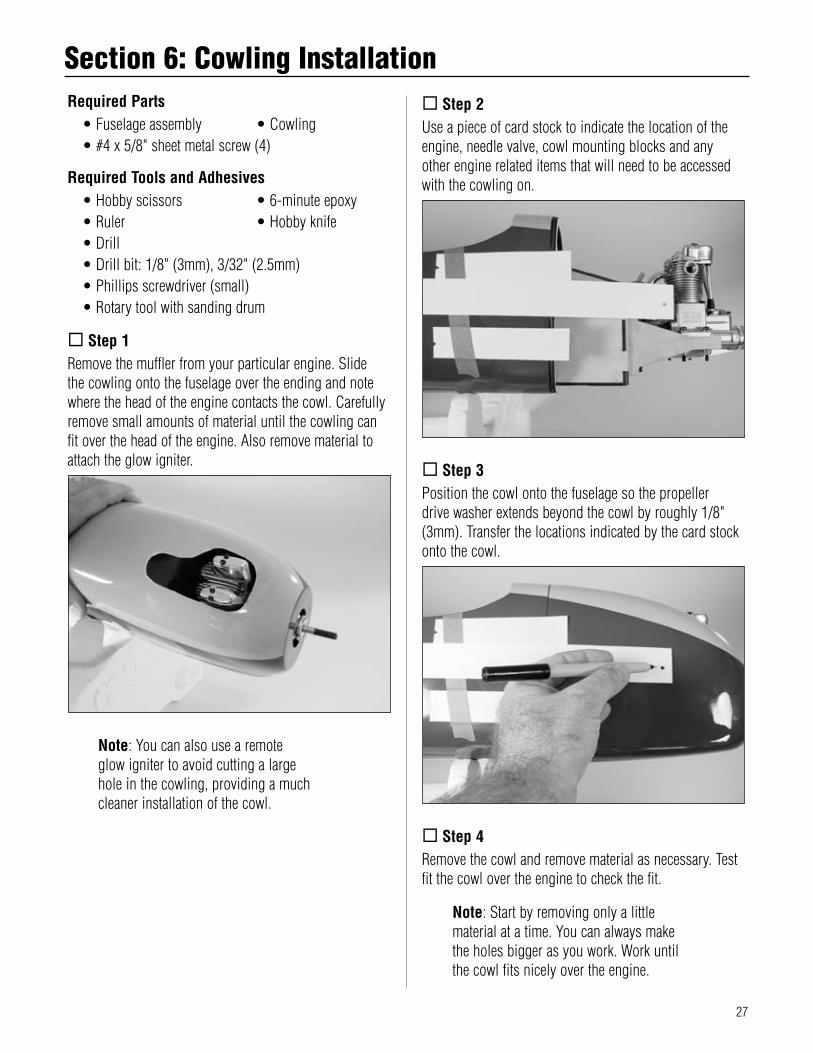
.Step 1Remove.the.muffler.from.your.particular.engine..Slide..the.cowling.onto.the.fuselage.over.the.ending.and.note.where.the.head.of.the.engine.contacts.the.cowl..Carefully.remove.small.amounts.of.material.until.the.cowling.can.fit.over.the.head.of.the.engine..Also.remove.material.to.attach.the.glow.igniter.
Note:.You.can.also.use.a.remote.glow.igniter.to.avoid.cutting.a.large.hole.in.the.cowling,.providing.a.much.cleaner.installation.of.the.cowl.
.Step 2Use.a.piece.of.card.stock.to.indicate.the.location.of.the.engine,.needle.valve,.cowl.mounting.blocks.and.any..other.engine.related.items.that.will.need.to.be.accessed.with.the.cowling.on.
.Step 3Position.the.cowl.onto.the.fuselage.so.the.propeller..drive.washer.extends.beyond.the.cowl.by.roughly.1/8".(3mm)..Transfer.the.locations.indicated.by.the.card.stock.onto.the.cowl.
.Step 4Remove.the.cowl.and.remove.material.as.necessary..Test.fit.the.cowl.over.the.engine.to.check.the.fit.
Note:.Start.by.removing.only.a.little.material.at.a.time..You.can.always.make.the.holes.bigger.as.you.work..Work.until.the.cowl.fits.nicely.over.the.engine.
Section 6: Cowling Installation

28
.Step 5Slide.the.cowling.onto.the.fuselage.so.it.is.tight.against.the.fuselage..Also.check.that.the.drive.washer.is.centered.in.the.opening.at.the.front.of.the.cowl..Mark.the.position.for.the.screws.to.secure.the.cowl.to.the.cowl.mounting.blocks..Drill.the.locations.using.a.3/32".drill.bit.
.Step 6Enlarge.the.holes.drilled.in.the.cowling.using.a..1/8".(3mm).drill.bit.
.Step 7Attach.the.cowl.using.four.#4.x.5/8".sheet.metal..screws..Apply.a.couple.of.drops.of.CA.into.the.screw.holes.after.threading.the.screws.in.a.couple.of.times...This.will.harden.the.wood.and.keep.the.screws.from.loosening.during.flight.
.Step 8Attach.the.propeller.and.spinner.to.the.engine..Check.that.the.spinner.can.rotate.without.rubbing.on.the.cowling,.or.isn’t.positioned.with.too.much.of.a.gap.between.it.and.the.cowl..Reposition.the.engine.on.the.mount.if.necessary.for.a.perfect.gap.between.the.spinner.and.cowling.
.Step 9Glue.the.exhaust.stacks.to.the.cowling.using.6-minute.epoxy..Use.masking.tape.to.hold.the.exhaust.in.position.until.the.epoxy.fully.cures.
Section 6: Cowling Installation

29
Required Parts•.Fuselage.assembly. •.Rudder•.Radio.tray. •.Nylon.clevis•.Tail.wheel.assembly•.#2.x.3/8".sheet.metal.screw.(2)•.29.
1/2".(750mm).pushrod.wire•.Heat.shrink.material•.Control.horn.w/backplate•.2-56.x.9/16”.machine.screw.(3)
Required Tools and Adhesives•.6-minute.epoxy. •.Thin.CA•.Drill. •.Drill.bit:.1/8".(3mm)•.T-pins. •.Hobby.knife
.Step 1Use.hobby.knife.to.remove.the.covering.from.the..bottom.of.the.rudder.to.expose.the.hole.and.groove..for.the.tail.gear.
.Step 2Roughen.the.tail.gear.wire.using.medium.grit.sandpaper.where.it.will.enter.the.rudder..Use.6-minute.epoxy.to.glue.the.wire.into.the.rudder.
.Step 3Locate.three.CA.hinges..Place.a.T-pin.in.the.center.of.the.hinges..Place.the.hinges.into.the.rudder.
.Step 4Slide.the.hinges.and.rudder.into.position..Check.that.the.gap.between.the.rudder.and.fin.is.roughly.1/64".(.5mm)..Apply.thin.CA.to.both.sides.of.the.hinges..Perform.the.pull.test.after.the.CA.has.fully.cured.
Section 7: Rudder Installation

30
.Step 5Secure.the.tail.wheel.bracket.to.the.fuselage.using.two..#2.x.3/8".sheet.metal.screws.
.Step 6Use.6-minute.epoxy.to.glue.the.radio.tray.into..the.fuselage.
.Step 7Install.the.rudder.servo.using.the.hardware.provided..with.the.servo.or.radio.system.
.Step 8Slide.one.of.the.29.
1/2".(750mm).pushrods.into.the.rudder.pushrod.tube.from.the.inside..Use.a.hobby.knife.to.trim.the.covering.from.the.fuselage.where.the.pushrod.exits..Cut.a.1/4".(6mm).piece.of.heat.shrink.and.place.it.over.a.nylon.clevis..Thread.the.clevis.onto.the.pushrod.wire.a.minimum.of.12.turns.
Section 7: Rudder Installation

31
.Step 9Remove.the.backplate.from.a.control.horn..Snap.the..clevis.onto.the.horn.and.position.the.horn.on.the.rudder..Use.a.felt-tipped.pen.to.mark.the.location.for.the.three.mounting.screws.
.Step 10Attach.the.control.horn.using.the.backplate.and.three..2-56.x.9/16".machine.screws.
.Step 11With.both.the.rudder.servo.and.rudder.centered,.mark.the.rudder.pushrod.at.the.hole.it.crosses.in.the.rudder.servo.arm.using.a.felt-tipped.pen.
.Step 12Enlarge.the.outer.hole.in.the.rudder.servo.arm.using.a.5/64".(2mm).drill.bit..Bend.the.pushrod.wire.at.the.mark.made.in.the.last.step..Pass.the.wire.through.the.servo.arm.and.secure.it.using.a.nylon.wire.keeper..Remove.any.unused.arms.from.the.servo.horn.
Section 7: Rudder Installation

32
Required Parts•.Assembled.wing. •.Fuselage•.Stabilizer. •.Elevator.joiner.wire•.1/4-20.blind.nut.(2). •.1/4".washer.(2)•.Elevator.joiner.wire. •.CA.hinge.(6)•.1/4-20.x.1.
1/2".socket.head.bolt.(2)•.Elevator.(left.and.right)
Required Tools and Adhesives•.Hobby.knife. •.Felt-tipped.pen•.Ruler. •.Sandpaper•.30-minute.epoxy. •.Pliers•.Thin.CA. •.T-pins•.Drill. •.Hex.wrench:.3/16"•.Drill.bit:.9/64".(3.5mm)
.Step 1Use.a.sharp.hobby.knife.to.remove.the.covering.from.the.slot.in.the.rear.of.the.fuselage.for.the.stabilizer.
.Step 2Locate.the.two.1/4-20.blind.nuts..Mix.a.small.amount.of.30-minute.epoxy.and.apply.it.to.the.barbs.of.the.blind.nut..Use.pliers.or.a.C-clamp.to.install.the.blind.nut.from.the.inside.of.the.fuselage.
Note:.Make.sure.no.epoxy.gets.into.the.threads.of.the.blind.nut.
Hint:.A.1/4-20.bolt.and.large.washer.can.be.used.to.draw.the.blind.nut.into.position.as.well.
Section 8: Stabilizer Installation

33
.Step 3Use.the.two.1/4.x.1.
1/2".socket.head.bolts.and..1/4".washers.to.attach.the.wing.to.the.fuselage.
.Step 4Measure.the.distance.between.a.point.centered.at.the.rear.of.the.fuselage.and.each.wing.tip..The.measurement.will.be.equal.if.the.wing.is.aligned.correctly..If.the.measurement.is.not.the.same,.slightly.oval.the.hole.for.the.wing.bolts.until.an.equal.measurement.is.achieved.
A A
A=A
.Step 5Slide.the.stabilizer.into.the.fuselage,.making.sure.it.is.as.far.forward.as.possible..Center.the.stab.in.the.opening.by.measuring.the.distance.from.the.fuselage.to.each.tip..The.stab.is.aligned.when.both.measurements.are.identical.
.Step 6Check.the.distance.from.each.stab.tip.to.each.wing..tip..These.measurements.must.be.equal.for.the.stab..to.be.aligned.
A A
A=A
.Step 7Check.to.make.sure.the.wing.and.stabilizer.are.parallel..If.they.are.not,.lightly.sand.the.opening.in.the.fuselage.for.the.stab.until.the.stab.is.parallel.to.the.wing.
Parallel
Section 8: Stabilizer Installation

34
.Step 8After.verifying.the.alignment.of.the.stabilizer,.use.a.felt-tipped.pen.to.trace.the.outline.of.the.fuselage.on.the.top.and.bottom.of.the.stab.
.Step 9Remove.the.stab.and.use.a.hobby.knife.with.a.new.blade.to.remove.the.covering.1/16".(1.5mm).inside.the.lines.just.drawn..Use.rubbing.alcohol.and.a.paper.towel.to.remove.the.lines.once.they.are.no.longer.needed.
Note:.Use.care.not.to.cut.into.the.underlying.wood.and.weaken.the.structure..Doing.so.could.cause.the.stab.to.fail.in.flight,.resulting.in.the.loss.of.your.airplane.
Hint:.You.can.also.use.a.soldering.iron.or.hot.knife.to.cut.the.covering..The.heat.will.help.melt.the.covering,.rather.than.applying.pressure.and.possibly.cutting.into.the.stabilizer.
.Step 10Slide.the.elevator.joiner.wire.into.the.slot.for.the.stabilizer..Slide.the.stabilizer.partially.back.into.the.slot..Mix.1/2.ounce.of.30-minute.epoxy..Apply.epoxy.to.the.top.and.bottom.of.the.exposed.wood.of.the.stabilizer..Slide.the.stabilizer.the.rest.of.the.way.into.the.slot.in.the.fuselage..Double-check.the.alignment.to.verify.it’s.correct..Remove.any.excess.epoxy.using.a.paper.towel.and.rubbing.alcohol..Allow.the.epoxy.to.fully.cure.before.continuing.
Note:.Continually.check.the.alignment.of.the.stabilizer.while.the.epoxy.cures.
Section 8: Stabilizer Installation

35
..Step 11Locate.one.of.the.elevator.halves..Remove.the.covering.from.the.slot.in.the.elevator..Locate.three.CA.hinges...Place.a.T-pin.in.the.center.of.the.hinges..Place.the.hinges.into.the.elevator.half.
..Step 12Test.fit.the.elevator.and.stab.together..The.elevator.joiner.wire.will.be.inserted.into.the.hole.drilled.in.the.elevator.
..Step 13Lightly.sand.the.joiner.wire.where.it.enters.the.elevator..Mix.1/2.ounce.of.30-minute.epoxy.and.apply.it.to.the.groove.and.hole.in.the.elevator.half..Insert.the.elevator.joiner.wire..Remove.any.excess.epoxy.using.rubbing.alcohol.and.a.paper.towel.
Note:.You.can.combine.the.previous.step.with.the.following.step.if.you.like..This.will.hold.the.elevator.in.position.while.the.epoxy.cures.
..Step 14Check.to.make.sure.the.elevator.moves.freely..Check.to.make.sure.the.hinge.gap.between.the.elevator.and.stabilizer.is.roughly.1/64".(.5mm)..Apply.thin.CA.to.both.sides.of.the.hinge..Make.sure.to.saturate.the.hinge.and.don’t.use.accelerator.
..Step 15Once.the.CA.and.epoxy.have.fully.cured,.gently.pull..on.the.elevator.and.stab.to.make.sure.the.hinges.are..well.glued..Flex.the.elevators.a.few.times.to.break.in..the.hinges.
.Step 16Repeat.Steps.11.through.15.to.install.the.remaining.elevator.half.
Section 8: Stabilizer Installation
36
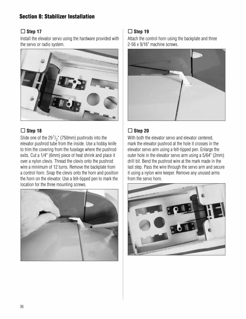
.Step 17Install.the.elevator.servo.using.the.hardware.provided.with.the.servo.or.radio.system.
.Step 18Slide.one.of.the.29.
1/2".(750mm).pushrods.into.the.elevator.pushrod.tube.from.the.inside..Use.a.hobby.knife.to.trim.the.covering.from.the.fuselage.where.the.pushrod.exits..Cut.a.1/4".(6mm).piece.of.heat.shrink.and.place.it.over.a.nylon.clevis..Thread.the.clevis.onto.the.pushrod.wire.a.minimum.of.12.turns..Remove.the.backplate.from.a.control.horn..Snap.the.clevis.onto.the.horn.and.position.the.horn.on.the.elevator..Use.a.felt-tipped.pen.to.mark.the.location.for.the.three.mounting.screws.
.Step 19Attach.the.control.horn.using.the.backplate.and.three..2-56.x.9/16".machine.screws.
.Step 20With.both.the.elevator.servo.and.elevator.centered,..mark.the.elevator.pushrod.at.the.hole.it.crosses.in.the.elevator.servo.arm.using.a.felt-tipped.pen..Enlarge.the.outer.hole.in.the.elevator.servo.arm.using.a.5/64".(2mm).drill.bit..Bend.the.pushrod.wire.at.the.mark.made.in.the.last.step..Pass.the.wire.through.the.servo.arm.and.secure.it.using.a.nylon.wire.keeper..Remove.any.unused.arms.from.the.servo.horn.
Section 8: Stabilizer Installation

37
Required Parts•.Fuselage.assembly. •.Canopy•.Decal•#2.x.1/2".sheet.metal.screw.(2)
Required Tools and Adhesives•.Receiver. •.Receiver.battery•.Canopy.glue.(Formula.560). •.1/4".(6mm).foam•.Sandpaper.(medium.grit). •.Hobby.scissors•.Zap-A-Dap-A-Goo. •.6-minute.epoxy
.Step 1Wrap.the.receiver.and.receiver.battery.in.1/4".(6mm)..foam.to.prevent.them.from.becoming.damaged.by..engine.vibrations.
.Step 2Plug.the.servos,.switch.harness.and.any.necessary.servo.extensions.into.the.receiver.at.this.time.
.Step 3Secure.the.receiver.and.receiver.battery.to.the.radio.tray..Use.hook.and.loop.straps,.tape,.or.rubber.bands.to.hold.them.securely.to.the.tray.
.Step 4Route.the.receiver.antenna.to.the.rear.of.the.fuselage..Do.not.cut.the.antenna.as.this.will.greatly.reduce.the.range.of.the.radio.system.
.Step 5Mount.the.switch.harness.to.the.side.of.the.fuselage.opposite.that.of.the.engine.exhaust.
.Step 6Paint.and.install.a.pilot.of.your.choosing..Use.epoxy.or.Zap-A-Dap-A-Goo.to.secure.the.pilot.
Section 9: Final Assembly

38
.Step 7Use.hobby.scissors.to.trim.the.backrest..Use.Zap-A-Dap-A-Goo.to.glue.the.backrest.into.position.
.Step 8Trim.the.instrument.panel.decal.and.apply.it.into.position.
.Step 9Use.Lexan.scissors.to.trim.the.canopy.
.Step 10Position.the.canopy.onto.the.fuselage..Trace.around.the.canopy.and.onto.the.fuselage.using.a.felt-tipped.pen.
.Step 11Lightly.sand.the.inside.edge.of.the.canopy.and..slightly.inside.the.line.drawn.on.the.hatch.using..medium.sandpaper.
Section 9: Final Assembly

39
.Step 12Apply.a.bead.of.RCZ56.Canopy.Glue.(ZINJ5007).around.the.inside.edge.of.the.canopy..Position.the.canopy.onto.the.hatch..Use.tape.to.hold.the.canopy.secure.until.the.glue.fully.cures.
.Step 13Apply.the.decals..Use.the.photos.on.the.box.to.aid..in.their.location.
.Step 14Position.the.forward.scoop.on.the.wing.and.trace.around.it.using.a.felt-tipped.pen..Remove.the.covering.1/16".(1.5mm).inside.the.lines..Use.canopy.glue.to.secure.the.scoop.to.the.wing.
.Step 15Use.the.same.procedure.to.attach.the.radiators.onto..the.bottom.of.the.wing.using.canopy.glue.in.the..locations.shown.
.Step 16The.last.detail.is.to.install.the.antenna.onto.the.fuselage..Use.a.hobby.knife.to.cut.a.slot.in.the.top.of.the.fuselage.for.the.antenna.
Section 9: Final Assembly

40
.Step 1Completely.read.the.instructions.included.with.your.engine.and.follow.the.recommended.break-in.procedure.
.Step 2At.the.field,.adjust.the.engine.to.a.slightly.rich.setting.at.full.throttle.and.adjust.the.idle.and.low-speed.needle.so.that.a.consistent.idle.is.achieved.
.Step 3Before.you.fly,.be.sure.that.your.engine.idles..reliably,.transitions.and.runs.at.all.throttle.settings...Only.when.this.is.achieved.should.any.plane.be.considered.ready.for.flight.
Adjusting the Engine
Control ThrowsThe.amount.of.control.throw.should.be.adjusted.as.closely.as.possible.using.mechanical.means,.rather.than.making.large.changes.electronically.at.the.radio..By.moving.the.position.of.the.clevis.at.the.control.horn.toward.the.outermost.hole,.you.will.decrease.the.amount.of.control.throw.of.the.control.surface..Moving.it.toward.the.control.surface.will.increase.the.amount.of.throw..Moving.the.pushrod.wire.at.the.servo.arm.will.have.the.opposite.effect:.Moving.it.closer.to.center.will.decrease.throw,.and.away.from.center.will.increase.throw..Work.with.a.combination.of.the.two.to.achieve.the.closest.or.exact.control.throws.listed.
AileronLow.Rate:. 1/2".(11°).up,.7/16".(10°).downHigh.Rate:. 3/4".(16°).up,.11/16".(13°).down
ElevatorLow.Rate:. 1/2".(8°).up/downHigh.Rate:. 1".(16°).up/down
RudderLow.Rate:. 1".(16°).left/rightHigh.Rate:. 1.
1/4".(21°).left/right
FlapHalf.Flap:. 1/2".(15°)Full.Flap:. 1".(30°)
Important:.The.linear.measurements.for.the.elevator.and.rudder.are.made.at.the.widest.part.of.the.control.surface..The.linear.measurement.for.aileron.and.flap.throw.is.measured.on.the.end.where.they.meet;.the.inboard.end.of.aileron.and.outboard.end.of.flap.
Once.the.control.throws.have.been.set,.use.the.supplied.heat.shrink.tubing.on.each.clevis.to.prevent.them.from.opening.during.flight.

41
An.important.part.of.preparing.the.aircraft.for.flight.is.properly.balancing.the.model..This.is.especially.important.when.various.engines.are.mounted.Caution:.Do.not.inadvertently.skip.this.step!The.recommended.Center.of.Gravity.(CG).location.for.the.Spitfire.60.is.5.
1/4".(133mm).behind.the.leading.edge.of.the.wing.against.the.fuselage..Make.sure.the.aircraft.is.inverted.when.measuring.the.CG..If.necessary,.move.the.battery.pack.or.add.weight.to.either.the.nose.or.the.tail.until.the.correct.balance.is.achieved..Stick-on.weights.are.available.at.your.local.hobby.store.and.work.well.for.this.purpose.
Recommended Center of Gravity (CG)
Pre-FlightCharge.both.the.transmitter.and.receiver.pack.for.your.airplane..Use.the.recommended.charger.supplied.with.your.particular.radio.system,.following.the.instructions.provided.with.the.radio..In.most.cases,.the.radio.should.be.charged.the.night.before.going.out.flying.
Check.the.radio.installation.and.make.sure.all..the.control.surfaces.are.moving.correctly.(i.e..the..correct.direction.and.with.the.recommended.throws)...Test.run.the.engine.and.make.sure.it.transitions..smoothly.from.idle.to.full.throttle.and.back..Also.ensure.the.engine.is.tuned.according.to.the.manufacturer’s.instructions,.and.it.will.run.consistently.and.constantly..at.full.throttle.when.adjusted.Check.all.the.control.horns,.servo.horns.and.clevises.to.make.sure.they.are.secure.and.in.good.condition..Replace.any.items.that.would.be.considered.questionable..Failure.of.any.of.these.components.in.flight.would.mean.the.loss.of.your.aircraft.
Range Test Your RadioRange.check.your.radio.system.before.each.flying..session..This.is.accomplished.by.turning.on.your.transmitter.with.the.antenna.collapsed..Turn.on.the..radio.in.your.airplane..With.your.airplane.on.the..ground,.you.should.be.able.to.walk.30.paces.away.from.your.airplane.and.still.have.complete.control.of..all.functions..If.not,.don’t.attempt.to.fly!.Have.your.radio.equipment.checked.out.by.the.manufacturer.

42
GENERAL1).I.will.not.fly.my.model.aircraft.in.sanctioned.events,.air.shows.or.model.flying.demonstrations.until.it.has.been.proven.to.be.airworthy.by.having.been.previously,.successfully.flight.tested.2).I.will.not.fly.my.model.higher.than.approximately.400.feet.within.3.miles.of.an.airport.without.notifying.the.airport.operator..I.will.give.right-of-way.and.avoid.flying.in.the.proximity.of.full-scale.aircraft..Where.necessary,.an.observer.shall.be.utilized.to.supervise.flying.to.avoid.having.models.fly.in.the.proximity.of.full-scale.aircraft.3).Where.established,.I.will.abide.by.the.safety.rules.for.the.flying.site.I.use,.and.I.will.not.willfully.and.deliberately.fly.my.models.in.a.careless,.reckless.and/or.dangerous.manner.4).The.maximum.takeoff.weight.of.a.model.is.55.pounds,.except.models.flown.under.Experimental.Aircraft.rules.5).I.will.not.fly.my.model.unless.it.is.identified.with.my.name.and.address.or.AMA.number,.on.or.in.the.model..(This.does.not.apply.to.models.while.being.flown.indoors.)6).I.will.not.operate.models.with.metal-bladed.propellers.or.with.gaseous.boosts,.in.which.gases.other.than.air.enter.their.internal.combustion.engine(s);.nor.will.I.operate.models.with.extremely.hazardous.fuels.such.as.those.containing.tetranitromethane.or.hydrazine.
7).I.will.not.operate.models.with.pyrotechnics.(any.device.that.explodes,.burns,.or.propels.a.projectile.of.any.kind).including,.but.not.limited.to,.rockets,.explosive.bombs.dropped.from.models,.smoke.bombs,.all.explosive.gases.(such.as.hydrogen-filled.balloons),.or.ground.mounted.devices.launching.a.projectile..The.only.exceptions.permitted.are.rockets.flown.in.accordance.with.the.National.Model.Rocketry.Safety.Code.or.those.permanently.attached.(as.per.JATO.use);.also.those.items.authorized.for.Air.Show.Team.use.as.defined.by.AST.Advisory.Committee.(document.available.from.AMA.HQ)..In.any.case,.models.using.rocket.motors.as.a.primary.means.of.propulsion.are.limited.to.a.maximum.weight.of.3.3.pounds.and.a.G.series.motor..(A.model.aircraft.is.defined.as.an.aircraft.with.or.without.engine,.not.able.to.carry.a.human.being.)8).I.will.not.consume.alcoholic.beverages.prior.to,..nor.during,.participation.in.any.model.operations.9).Children.under.6.years.old.are.only.allowed..on.the.flight.line.as.a.pilot.or.while.receiving..flight.instruction.
RADIO CONTROL1).I.will.have.completed.a.successful.radio.equipment.ground.range.check.before.the.first.flight.of.a.new.or.repaired.model.2).I.will.not.fly.my.model.aircraft.in.the.presence.of.spectators.until.I.become.a.qualified.flier,.unless.assisted.by.an.experienced.helper.3).At.all.flying.sites.a.straight.or.curved.line(s).must.be.established.in.front.of.which.all.flying.takes.place.with.the.other.side.for.spectators..Only.personnel.involved.with.flying.the.aircraft.are.allowed.at.or.in.the.front.of.the.flight.line..Intentional.flying.behind.the.flight.line.is.prohibited.4).I.will.operate.my.model.using.only.radio.control.frequencies.currently.allowed.by.the.Federal.Communications.Commission..(Only.properly.licensed.Amateurs.are.authorized.to.operate.equipment.on.Amateur.Band.frequencies.)
2006 Official AMA National Model Aircraft Safety Code

43
5).Flying.sites.separated.by.three.miles.or.more.are.considered.safe.from.site-to.site.interference,.even.when.both.sites.use.the.same.frequencies..Any.circumstances.under.three.miles.separation.require.a.frequency.management.arrangement,.which.may.be.either.an.allocation.of.specific.frequencies.for.each.site.or.testing.to.determine.that.freedom.from.interference.exists..Allocation.plans.or.interference.test.reports.shall.be.signed.by.the.parties.involved.and.provided.to.AMA.Headquarters..Documents.of.agreement.and.reports.may.exist.between.(1).two.or.more.AMA.Chartered.Clubs,.(2).AMA.clubs.and.individual.AMA.members.not.associated.with.AMA.Clubs,.or.(3).two.or.more.individual.AMA.members.6).For.Combat,.distance.between.combat.engagement.line.and.spectator.line.will.be.500.feet.per.cubic.inch.of.engine.displacement..(Example:..40.engine.=.200.feet.);.electric.motors.will.be.based.on.equivalent.combustion.engine.size..Additional.safety.requirements.will.be.per.the.RC.Combat.section.of.the.current.Competition.Regulations.7).At.air.shows.or.model.flying.demonstrations,.a.single.straight.line.must.be.established,.one.side.of.which.is.for.flying,.with.the.other.side.for.spectators.8).With.the.exception.of.events.flown.under.AMA.Competition.rules,.after.launch,.except.for.pilots.or.helpers.being.used,.no.powered.model.may.be.flown.closer.than.25.feet.to.any.person.9).Under.no.circumstances.may.a.pilot.or.other.person.touch.a.powered.model.in.flight.
Organized RC Racing Event10).An.RC.racing.event,.whether.or.not.an.AMA.Rule.Book.event,.is.one.in.which.model.aircraft.compete.in.flight.over.a.prescribed.course.with.the.objective.of.finishing.the.course.faster.to.determine.the.winner.A..In.every.organized.racing.event.in.which.contestants,.callers.and.officials.are.on.the.course:1..All.officials,.callers.and.contestants.must.properly.wear.helmets,.which.are.OSHA,.DOT,.ANSI,.SNELL.or.NOCSAE.approved.or.comparable.standard.while.on.the.racecourse.2..All.officials.will.be.off.the.course.except.for.the.starter.and.their.assistant.3.”On.the.course”.is.defined.to.mean.any.area.beyond.the.pilot/staging.area.where.actual.flying.takes.place.B..I.will.not.fly.my.model.aircraft.in.any.organized.racing.event.which.does.not.comply.with.paragraph.A.above.or.which.allows.models.over.20.pounds.unless.that.competition.event.is.AMA.sanctioned.C..Distance.from.the.pylon.to.the.nearest.spectator.(line).will.be.in.accordance.with.the.current.Competition.Regulations.under.the.RC.Pylon.Racing.section.for.the.specific.event.pending.two.or.three.pylon.course.layout.11).RC.night.flying.is.limited.to.low-performance.models.(less.than.100.mph)..The.models.must.be.equipped.with.a.lighting.system.that.clearly.defines.the.aircraft’s.position.in.the.air.at.all.times.
2006 Official AMA National Model Aircraft Safety Code

©.2006.Horizon.Hobby,.Inc..4105.Fieldstone.Road.
Champaign,.Illinois.61822.(877).504-0233.
horizonhobby.com
9380