Embed Size (px)
Citation preview
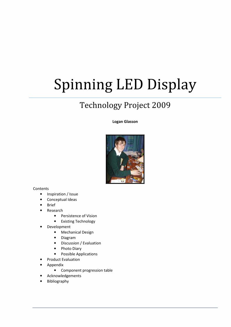
Spinning LED Display
Technology Project 2009
Logan Glasson
Contents
• Inspiration / Issue
• Conceptual Ideas
• Brief
• Research
• Persistence of Vision
• Existing Technology
• Development
• Mechanical Design
• Diagram
• Discussion / Evaluation
• Photo Diary
• Possible Applications
• Product Evaluation
• Appendix
• Component progression table
• Acknowledgements
• Bibliography

Inspiration / Issue
After seeing a LED message fan, Dad suggested that I could make one. A shop bought
fan is a handheld fan with 9 LEDs along the rotor blade. It has three buttons that can
be used to program different messages into the fan. The downsides are that it is
limited to displaying text and special characters, and it shows them in a circle, so
some of the text appears upside down.
Conceptual Ideas
In working with Dad as my client we developed a goal. I was challenged to make a large spinning LED
display that can be programmed to display straight lines, text or pictures. The display must visually
remain still and be easily reprogrammed.
Brief
I identified the following specifications to design to:
• Can show monochrome bitmap images such as:
• Squares
• Straight lines
• Straight text
• Offset circles
• Pictures
• Is easily loadable from a computer via a means such as:
• Cable connection
• Bluetooth
• Infrared connection
• Shows large images clearly in daylight
• Shows a constant image at different speeds
It is interesting to note that the last 3 design specs evolved over time as I discovered that these things
were possible and or desirable. In this way the original brief was extended.

Research
Persistence of Vision
The phenomenon displayed in my device is called persistence of vision (POV). Basically, it is why you see a
blur when something moves really fast. My project flashes the LED’s on and off in certain positions. At any
moment only one line of the image is illuminated but due to the speed of the disc and POV, a complete
image can be distinguished. This is only because the human eye has a relatively slow ‘shutter speed’ of
1\50 of a second. This means that if something raced through your field of view in less than a 50th of a
second, you wouldn’t see it (much). From this value you could say that my disc needs to make 50
complete revolutions every second for an effective image to appear. Luckily, the human brain is clever
enough to comprehend an image from my disc when it is spinning as slow as 10 times per second. A
standard camera has a shutter speed of 1\250. There is no way my disc will ever spin 250 times a second,
therefore to catch a photo of my disc you need to set a very slow shutter speed.
Existing technology
While creating this project I looked on the internet to see if a similar thing had been done before. A
Google search returned several displays, although most are just made by hobbyists; not commercial. All
but one of the displays I saw relies on a constant or near constant motor speed, which makes mine
unique. The one display that works with variable speed is a kitset from an online store. It is called
SpokePOV, and funnily enough, it goes on the spokes of a bike! The downside to this kitset is that
although it has rather high resolution, the software does not contain a utility for converting bitmap
images so anything it displays has to be able to be drawn in the SpokePOV program.

Design Brief Development
Mechanical Design
Before embarking on the electronic side of this project I needed to make a spinning device. At this stage
Dad was a great help to me, teaching me how to use a lathe and helping me machine the parts needed to
make a smooth spinning disc. I admit that Dad did the welding. Thanks Dad. The original trial was a hand
spun version. It soon became obvious that a motor would greatly help. Again Dad helped me in this
aspect, mounting a motor behind to achieve a constant spin. As the project progressed, in discussion
with my client (Dad) it became clear that a display that was turned by hand would not only be more
appropriate for a Science Fair but that having it work under varying speeds would actually be a design
strength and make it more commercially useful. This became part of the goal.
I am using the lathe to machine
the spinning disc

Diagram
This is a summary of the development of my final product.

Development Discussion / Evaluation
PICAXE microcontrollers are common, easy to program, simple chips. I used this chip in my original
version, but found it too slow with not enough outputs to drive the number of LED’s I wanted to use.
After pursuing with the PICAXE and sorting out timing issues I then looked into suitable options for a
better microprocessor. Richard Daly, of Tait Electronics had talked to me about the ATtiny2313
microprocessor when I visited there once. I decided to give them a go. The ATtiny2313 is far more
powerful than a PICAXE (at only $5.40 it operates up to 20000 times faster). It has 18 input/output pins
and can store 2 kilobytes of code. It has all the features needed for my project, including 2 internal timers,
interrupt capability, and enough memory to store 10 images. With the increased ability of the ATtiny2313
came a new challenge for me. I had to learn to program in “C” in order to use it. This in itself was a time
consuming but rewarding aspect of the project.
Originally I was not aware of the severe speed and hardware limitations of the PICAXE, therefore I
envisaged a system that timed its position based on one pulse per revolution. In version one I used a reed
switch. A reed switch consists of two metal plates that sit close to each other. When influenced by a
magnetic field they move together and conduct electricity. This didn’t work well because it is mechanical
and therefore slow. I did achieve one crude wavering dot with this version. For a while I experimented
with self timing. This is where the chip assumes a constant speed and works from that to position the
display. From this I got some basic circular text to display, similar to the original gimmick LED fan. I knew
that an optical switch would work better if I could get it working. An optical switch sends a light beam
across a gap. It detects when the gap is obstructed. After hours testing different resistor values and wiring
configurations I finally mastered the optical switch. It revolutionised the timing aspect of my project,
allowing reliable data about the position to be acquired. I was still frustrated by the PICAXE being so slow.
Instead of having a one toothed disc I devised a new timing method. I cut a disc with 72 teeth so the
PICAXE would not need to do any timing. This worked, but there were several disadvantages. There was
no indication of orientation, so the unit would display semi-rotated images at random and the 72 toothed
disc itself was very delicate (and time consuming to make). It was using an optical switch in combination
with an ATtiny2313 that finally achieved what I’d been aiming at. Fast, clear data acquisition, processing
and display.
I went through lots of LEDs making this project. In my prototype circuits I used standard 5mm red LEDs.
They were fine for archetype circuits, but didn’t show up well in light environments. When I was putting
together the final PICAXE circuits I used super bright 3mm blue LEDs. I got some of these from the
BrightSparks LED pack, and bought more from SICOM. When I put together the final ATtiny2313 circuit I
got super bright 3mm red LEDs. Unlike the blue LEDs, these ones had a wide viewing angle, so they
appear just as bright from the side. I also filed the edges off these LEDs so they fitted closer together. This
gives the image a higher resolution.

Photo Diary
I am using the lathe Prototype 1:
The reed switch version
Prototype 2:
Self timed version
Prototype 2 in action
Final PICAXE circuit The 72 toothed disc The optical switch
POV person Mum’s message One of the standard 10 digits I have
loaded in
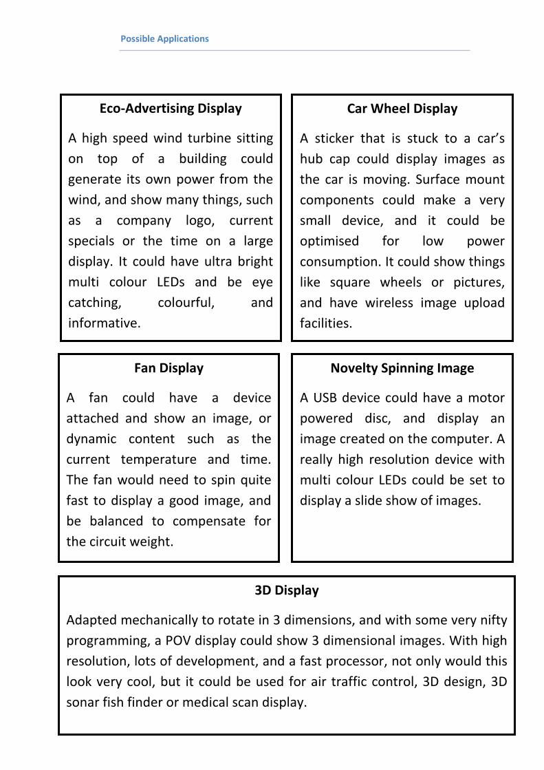
Possible Applications
Eco-Advertising Display
A high speed wind turbine sitting
on top of a building could
generate its own power from the
wind, and show many things, such
as a company logo, current
specials or the time on a large
display. It could have ultra bright
multi colour LEDs and be eye
catching, colourful, and
informative.
Car Wheel Display
A sticker that is stuck to a car’s
hub cap could display images as
the car is moving. Surface mount
components could make a very
small device, and it could be
optimised for low power
consumption. It could show things
like square wheels or pictures,
and have wireless image upload
facilities.
Fan Display
A fan could have a device
attached and show an image, or
dynamic content such as the
current temperature and time.
The fan would need to spin quite
fast to display a good image, and
be balanced to compensate for
the circuit weight.
Novelty Spinning Image
A USB device could have a motor
powered disc, and display an
image created on the computer. A
really high resolution device with
multi colour LEDs could be set to
display a slide show of images.
3D Display
Adapted mechanically to rotate in 3 dimensions, and with some very nifty
programming, a POV display could show 3 dimensional images. With high
resolution, lots of development, and a fast processor, not only would this
look very cool, but it could be used for air traffic control, 3D design, 3D
sonar fish finder or medical scan display.

Product Evaluation
Looking back on this project, I am quite happy. I have created what I believe is a unique combination of
software and hardware, and it satisfies my Brief. I could of course refine it further.
Since the Science Fair I have seen and demonstrated it to a visiting marketing bigwig from Auckland, and
SICOM, both of whom think it has great potential in advertising. SICOM even suggested getting me in
contact with one of their suppliers who they think might be interested.
I have completed my project to a suitable standard for a gimmick, but have identified to steps to take it
further. I would need to make a smaller circuit, with a larger, higher resolution, colour display and easier
loading. If I did this, I could easily package it and make it a commercial product. This is my final goal.

Appendix
Component progression table
In making my project I went through many different types of components. The following table outlines
the changes in components as I progressed.
Processor Sensor LEDs Base Description
PICAXE Reed Switch Standard 5mm red Breadboard Displayed a stationary dot.
PICAXE Self Timed Standard 5mm red Breadboard Displayed text like an LED
message fan
PICAXE Optical Switch Standard 5mm red Breadboard Test timing divider circuit
PICAXE Optical Switch Super Bright 3mm blue Veroboard Final PICAXE circuit
ATtiny2313 Optical Switch Standard 5mm red Breadboard Test timing divider circuit
ATtiny2313 Optical Switch Super Bright 3mm blue
with edges filed
Veroboard Final ATtiny2313 circuit
Acknowledgements
• Dad for help making the rotating disc, and troubleshooting my circuit.
• Mum for getting parts.
• Richard Daly from Tait Electronics for suggesting I use the ATtiny.
• Rob Stewart (from dads work) for help and advice with the ATtiny.
• Members of the AVRFreaks forum for help with programming and circuitry issues.
Bibliography
• http://www.petesqbsite.com/
• http://www.ladyada.net/make/spokepov/
• http://www.avrfreaks.net/
• http://www.wikipedia.org/
• http://www.sicom.co.nz/
• http://www.jaycar.co.nz/