Embed Size (px)
Citation preview
SPILLWAYS 1. INTRODUCTION
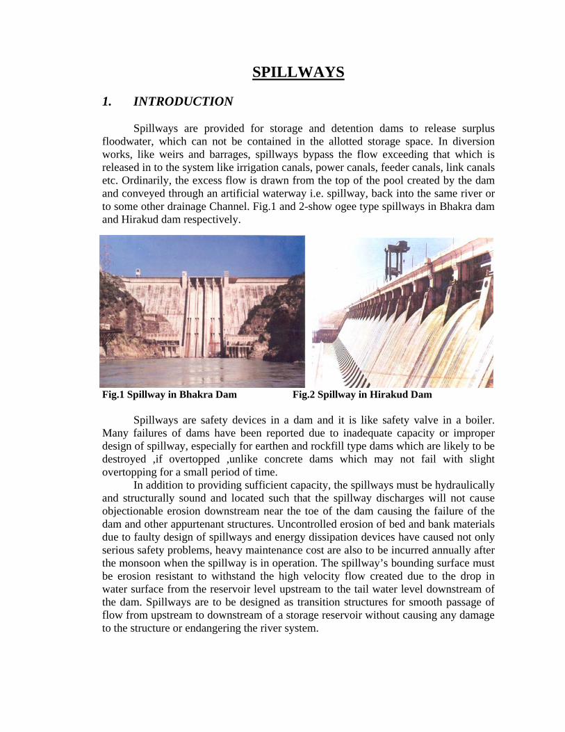
Spillways are provided for storage and detention dams to release surplus floodwater, which can not be contained in the allotted storage space. In diversion works, like weirs and barrages, spillways bypass the flow exceeding that which is released in to the system like irrigation canals, power canals, feeder canals, link canals etc. Ordinarily, the excess flow is drawn from the top of the pool created by the dam and conveyed through an artificial waterway i.e. spillway, back into the same river or to some other drainage Channel. Fig.1 and 2-show ogee type spillways in Bhakra dam and Hirakud dam respectively.
Fig.1 Spillway in Bhakra Dam Fig.2 Spillway in Hirakud Dam
Spillways are safety devices in a dam and it is like safety valve in a boiler. Many failures of dams have been reported due to inadequate capacity or improper design of spillway, especially for earthen and rockfill type dams which are likely to be destroyed ,if overtopped ,unlike concrete dams which may not fail with slight overtopping for a small period of time.
In addition to providing sufficient capacity, the spillways must be hydraulically and structurally sound and located such that the spillway discharges will not cause objectionable erosion downstream near the toe of the dam causing the failure of the dam and other appurtenant structures. Uncontrolled erosion of bed and bank materials due to faulty design of spillways and energy dissipation devices have caused not only serious safety problems, heavy maintenance cost are also to be incurred annually after the monsoon when the spillway is in operation. The spillway’s bounding surface must be erosion resistant to withstand the high velocity flow created due to the drop in water surface from the reservoir level upstream to the tail water level downstream of the dam. Spillways are to be designed as transition structures for smooth passage of flow from upstream to downstream of a storage reservoir without causing any damage to the structure or endangering the river system.
2. TYPES OF SPILLWAYS Spillways may be broadly categorized as service spillway and emergency type
spillway. The service spillways are those which are in constant use in every flood when the reservoir level exceeds the crest level of the spillway. An emergency spillway, also known as auxiliary spillway, is one which is rarely used and come into operation during extraordinary flood when the actual flood discharge exceeds the design capacity of the service spillway. Various types of service spillways in common use are briefly described below: 2.1 Vertical Drop type Spillway A vertical drop or free over fall type spillway is one in which the flow drops freely from the acres of the dam. This type is suited in a thin arch or a deck overflow type dam. Flows may be freely discharging, or they may be supported along a narrow section of the crest. Occasionally, the crest is extended in the form of an overhanging lip to direct small discharges away from the face of the overflow section. In free over fall spillways, the underside of the nappe is ventilated sufficiently to prevent a pulsating, fluctuating jet. Where no artificial protection is provided at the base of the over fall, scour will occur in most streambeds and will form a deep plunge pool. The volume and depth of the hole are related to the range of discharges, the height of the drop, and the depth of tailwater. The erosion-resistant properties of the streambed material including bedrock have little influence on the size of the hole, the only effect being the time necessary to scour the hole to its full depth. Such spillway can be provided only in case of low height dams on hard bed. In high dams these are not to be adopted, as it will subject the foundation to heavy scour and cause vibration leading to failure of the dam. 2.2 Ogee (overflow) Spillways
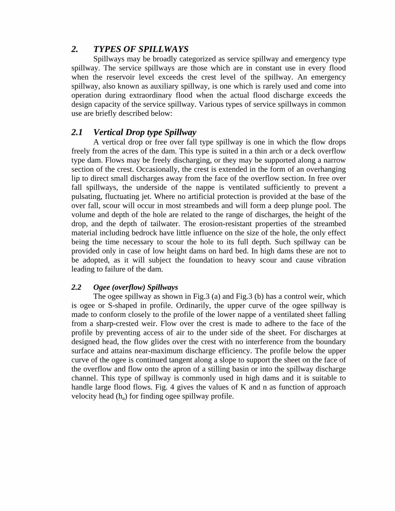
The ogee spillway as shown in Fig.3 (a) and Fig.3 (b) has a control weir, which is ogee or S-shaped in profile. Ordinarily, the upper curve of the ogee spillway is made to conform closely to the profile of the lower nappe of a ventilated sheet falling from a sharp-crested weir. Flow over the crest is made to adhere to the face of the profile by preventing access of air to the under side of the sheet. For discharges at designed head, the flow glides over the crest with no interference from the boundary surface and attains near-maximum discharge efficiency. The profile below the upper curve of the ogee is continued tangent along a slope to support the sheet on the face of the overflow and flow onto the apron of a stilling basin or into the spillway discharge channel. This type of spillway is commonly used in high dams and it is suitable to handle large flood flows. Fig. 4 gives the values of K and n as function of approach velocity head (ha) for finding ogee spillway profile.
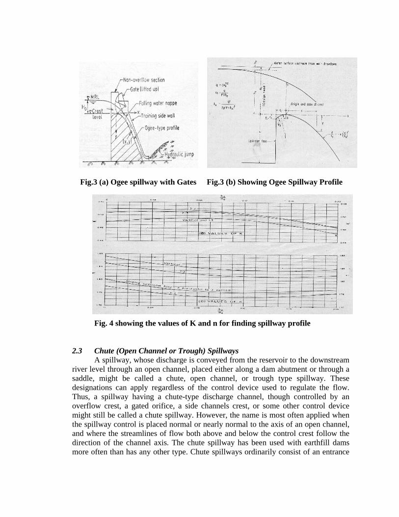
Fig.3 (a) Ogee spillway with Gates Fig.3 (b) Showing Ogee Spillway Profile
Fig. 4 showing the values of K and n for finding spillway profile 2.3 Chute (Open Channel or Trough) Spillways
A spillway, whose discharge is conveyed from the reservoir to the downstream river level through an open channel, placed either along a dam abutment or through a saddle, might be called a chute, open channel, or trough type spillway. These designations can apply regardless of the control device used to regulate the flow. Thus, a spillway having a chute-type discharge channel, though controlled by an overflow crest, a gated orifice, a side channels crest, or some other control device might still be called a chute spillway. However, the name is most often applied when the spillway control is placed normal or nearly normal to the axis of an open channel, and where the streamlines of flow both above and below the control crest follow the direction of the channel axis. The chute spillway has been used with earthfill dams more often than has any other type. Chute spillways ordinarily consist of an entrance
channel, a control structure, a discharge channel, a terminal structure, and an outlet channel. 2.4 Conduit and Tunnel Spillways
Where a closed channel is used to convey the discharge around or under a dam, the spillway is often called a tunnel or conduit spillway, as appropriate. The closed channel may take the form of a vertical or inclined shaft, a horizontal tunnel through earth or rock, or a conduit constructed in open cut and backfilled with earth materials. Most forms of control structures, including overflow crests, vertical or inclined orifice entrances, drop inlet entrances, and side channel crests, can be used with conduit and tunnel spillways. Tunnel spillways may present advantages for dam sited in narrow canyons with steep abutments or at sites where there is danger to open channels from snow or rockslides. Conduit spillways may be appropriate at dam sites in wide valleys, where the abutments rise gradually and are at a considerable distance from the stream channel. Use of a conduit will permit the spillway to be located under the dam near the streambed. 2.5 Drop Inlet (Shaft or Morning Glory) Spillways
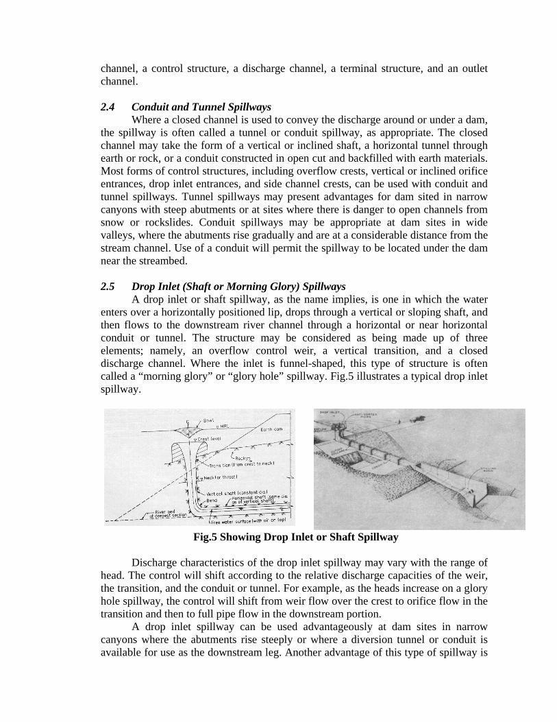
A drop inlet or shaft spillway, as the name implies, is one in which the water enters over a horizontally positioned lip, drops through a vertical or sloping shaft, and then flows to the downstream river channel through a horizontal or near horizontal conduit or tunnel. The structure may be considered as being made up of three elements; namely, an overflow control weir, a vertical transition, and a closed discharge channel. Where the inlet is funnel-shaped, this type of structure is often called a “morning glory” or “glory hole” spillway. Fig.5 illustrates a typical drop inlet spillway.
Fig.5 Showing Drop Inlet or Shaft Spillway
Discharge characteristics of the drop inlet spillway may vary with the range of head. The control will shift according to the relative discharge capacities of the weir, the transition, and the conduit or tunnel. For example, as the heads increase on a glory hole spillway, the control will shift from weir flow over the crest to orifice flow in the transition and then to full pipe flow in the downstream portion.
A drop inlet spillway can be used advantageously at dam sites in narrow canyons where the abutments rise steeply or where a diversion tunnel or conduit is available for use as the downstream leg. Another advantage of this type of spillway is
that near maximum capacity is attained at relatively low heads; This characteristic makes the spillway ideal for use where the maximum spillway outflow is to be limited. This characteristic also may be considered disadvantageous, in that there is little increase in capacity beyond the designed heads, should a flood occur. This would not be a disadvantage if this type of spillway were used as a service spillway in conjunction with an auxiliary or emergency spillway. 2.6 Culvert Spillway
A culvert spillway is a special adaptation of the conduit or tunnel spillway. It is distinguished from the drop inlet and other conduit types in that its inlet opening is placed either vertically or inclined upstream or downstream, and its profile grade is made uniform or near uniform and of any slopes. The spillway inlet opening might be sharp edged or rounded, and the approach to the conduit might have flared or tapered sidewalls with a level or sloping floor. If it is desired that the conduit flow partly full for all conditions of discharges, special precautions are taken to prevent the conduit from flowing full. Culvert spillways should not be used for high-head installations where large negative pressures can develop.
2.7 Siphon Spillways
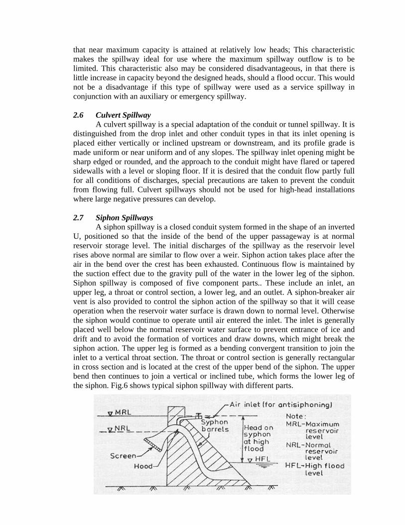
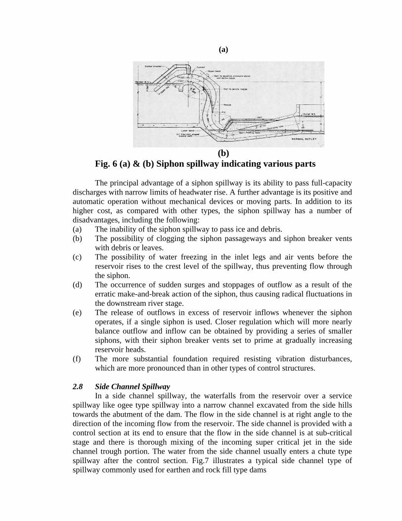
A siphon spillway is a closed conduit system formed in the shape of an inverted U, positioned so that the inside of the bend of the upper passageway is at normal reservoir storage level. The initial discharges of the spillway as the reservoir level rises above normal are similar to flow over a weir. Siphon action takes place after the air in the bend over the crest has been exhausted. Continuous flow is maintained by the suction effect due to the gravity pull of the water in the lower leg of the siphon. Siphon spillway is composed of five component parts.. These include an inlet, an upper leg, a throat or control section, a lower leg, and an outlet. A siphon-breaker air vent is also provided to control the siphon action of the spillway so that it will cease operation when the reservoir water surface is drawn down to normal level. Otherwise the siphon would continue to operate until air entered the inlet. The inlet is generally placed well below the normal reservoir water surface to prevent entrance of ice and drift and to avoid the formation of vortices and draw downs, which might break the siphon action. The upper leg is formed as a bending convergent transition to join the inlet to a vertical throat section. The throat or control section is generally rectangular in cross section and is located at the crest of the upper bend of the siphon. The upper bend then continues to join a vertical or inclined tube, which forms the lower leg of the siphon. Fig.6 shows typical siphon spillway with different parts.
(a)
(b) Fig. 6 (a) & (b) Siphon spillway indicating various parts The principal advantage of a siphon spillway is its ability to pass full-capacity
discharges with narrow limits of headwater rise. A further advantage is its positive and automatic operation without mechanical devices or moving parts. In addition to its higher cost, as compared with other types, the siphon spillway has a number of disadvantages, including the following: (a) The inability of the siphon spillway to pass ice and debris. (b) The possibility of clogging the siphon passageways and siphon breaker vents
with debris or leaves. (c) The possibility of water freezing in the inlet legs and air vents before the
reservoir rises to the crest level of the spillway, thus preventing flow through the siphon.
(d) The occurrence of sudden surges and stoppages of outflow as a result of the erratic make-and-break action of the siphon, thus causing radical fluctuations in the downstream river stage.
(e) The release of outflows in excess of reservoir inflows whenever the siphon operates, if a single siphon is used. Closer regulation which will more nearly balance outflow and inflow can be obtained by providing a series of smaller siphons, with their siphon breaker vents set to prime at gradually increasing reservoir heads.
(f) The more substantial foundation required resisting vibration disturbances, which are more pronounced than in other types of control structures.
2.8 Side Channel Spillway
In a side channel spillway, the waterfalls from the reservoir over a service spillway like ogee type spillway into a narrow channel excavated from the side hills towards the abutment of the dam. The flow in the side channel is at right angle to the direction of the incoming flow from the reservoir. The side channel is provided with a control section at its end to ensure that the flow in the side channel is at sub-critical stage and there is thorough mixing of the incoming super critical jet in the side channel trough portion. The water from the side channel usually enters a chute type spillway after the control section. Fig.7 illustrates a typical side channel type of spillway commonly used for earthen and rock fill type dams
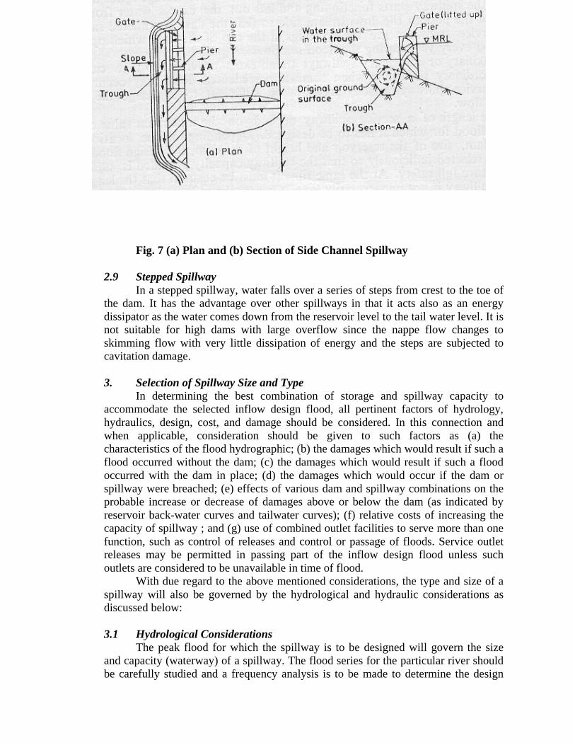
Fig. 7 (a) Plan and (b) Section of Side Channel Spillway 2.9 Stepped Spillway
In a stepped spillway, water falls over a series of steps from crest to the toe of the dam. It has the advantage over other spillways in that it acts also as an energy dissipator as the water comes down from the reservoir level to the tail water level. It is not suitable for high dams with large overflow since the nappe flow changes to skimming flow with very little dissipation of energy and the steps are subjected to cavitation damage. 3. Selection of Spillway Size and Type
In determining the best combination of storage and spillway capacity to accommodate the selected inflow design flood, all pertinent factors of hydrology, hydraulics, design, cost, and damage should be considered. In this connection and when applicable, consideration should be given to such factors as (a) the characteristics of the flood hydrographic; (b) the damages which would result if such a flood occurred without the dam; (c) the damages which would result if such a flood occurred with the dam in place; (d) the damages which would occur if the dam or spillway were breached; (e) effects of various dam and spillway combinations on the probable increase or decrease of damages above or below the dam (as indicated by reservoir back-water curves and tailwater curves); (f) relative costs of increasing the capacity of spillway ; and (g) use of combined outlet facilities to serve more than one function, such as control of releases and control or passage of floods. Service outlet releases may be permitted in passing part of the inflow design flood unless such outlets are considered to be unavailable in time of flood.
With due regard to the above mentioned considerations, the type and size of a spillway will also be governed by the hydrological and hydraulic considerations as discussed below: 3.1 Hydrological Considerations
The peak flood for which the spillway is to be designed will govern the size and capacity (waterway) of a spillway. The flood series for the particular river should be carefully studied and a frequency analysis is to be made to determine the design
peak flood of a given frequency which will be governed by the importance of the structure and its safety requirement. Usually, Gumbel’s probability equation or similar probability equations are used to find the design flood of a given frequency, which may vary from 1 in 50 years to 1 in 500 years-return period. If the failure of a dam leads to unprecedented loss of life and properties, maximum probable flood of high return period (say 1 in 500 years or more) should be considered for the design of the spillway capacity so that there is hardly any risk of failure and consequent damages. Obviously, the capacity of the spillway and its costs will be too high in such case. On the other hand, if the dam failure does not cause any loss of life or property, the spillway capacity can be substantially reduced considering peak flood of low return period (say 1 in 50 years or so).
The incoming peak flood should be routed as it passes through the reservoir upstream of the dam. Higher the storage capacity (due to greater height of dam), lower will be the routed flood peak for which the spillway capacity has to be provided. An economic analysis should be done to arrive at the best combination of storage capacity and the spillway size for optimum cost of spillway and appurtenant structures such as energy dissipater etc. 3.2 Hydraulic Considerations
Hydraulic design of various types of spillways narrated under item 2 is to be carefully done so as to avoid poor performance and failure of the structure and also to avoid high maintenance cost. For the detailed hydraulic design of different types of spillways, the relevant codes (given under references) should be followed. Hydraulic design involves consideration of the following aspects: (a) Fixing the crest Level. (b) Design of Waterway (c) Design of Spillway Profile (d) Design of Energy Dissipation Device (e) Design of aeration device (f) Design of Anti vortex Device (g) Design of Control Gates and their operation (h) Design of Outlet Works (i) Reservoir Operation Schedule (j) Desalting of Reservoirs 4. References: (i) IS:6934 “Recommendations for Hydraulic Design of High Ogee overflow
Spillways” by Bureau of Indian Standards, New Delhi (ii) IS:5186 “Criteria for Design of Chute and side Channel Spillways” by Bureau
of Indian Standards, New Delhi (iii) IS:6966 “Criteria for Hydraulic Design of Barrages and Weirs” by Bureau of
Indian Standards, New Delhi (iv) “Design of Small Dams” by U.S.B.R., Oxford and IBH Publishing Co. (v) “Engineering for Dams” Vol. 1, Wiley Eastern Pvt. Ltd. New Delhi by
Creager, Justin & Hinds,
(vi) “Morning-Glory Shaft Spillways,” by Peterika, A.J., Trans. ASCE, Vol. 121, 1956
(vii) “Morning-Glory Shaft Spillways Prototype Behavior”, by Bradley, J.N., Trans. ASCE, Vol. 121, 1956
(viii) “Open Channel Hydraulics” by Ven Te Chow, Mc Graw Hill & Co. New York (ix) “Stepped Spillways” by Haeger, W. Kluwer Academic Publishers London (x) “Reduction in Length of Stilling Basin due to Provision of Stepped Spillway”
by Khode B. V. and Hazare H.V., Proc. Hydro 2002 Dec. 16-17-2002, Organised by Indian Society for Hydraulics, Pune and IIT, Bombay
(xi) “Hydraulic Design of Spillway for run of River Scheme” by Bhosekar, Sridevi and Devolalikar,s Proc. Hydro 2002 Dec. 16-17-2002, Organised by Indian Society for Hydraulics, Pune and IIT, Bombay
(xii) “Proc. Of the Conference on Hydraulic Structures” July 6-7, 2001, organised by Indian Society for Hydraulics, Pune, and Bharti Vidyapeeth Deemed University, Pune
(xiii) National Symposium on “Recent Trends in Design of Hydraulic Structures” organised by Dept. of Civil Engineering, University of Roorkee and Indian Society for Hydraulics, Pune, March 18-19, 1994
(xiv) “Hydraulics of Closed Conduit Spillways- Part I – Theory and its application University of Minnesota, Saint Anthony Falls Hydraulic Laboratory, Technical Paper No. 12, series B, January 1952, revised February 1958
(xv) “Hydraulics of Closed Conduit Spillways- Part II through VII – Results of Tests on Several Forms of the Spillway,” University of Minnesota, Saint Anthony Falls Hydraulic Laboratory, Technical Paper No. 19, series B, March 1958
(xvi) “Design of Gravity Dams” by U.S.B.R., Denver, Colorado U.S.A. (xvii) “Hydraulic Engineering” by Roberson, Cassidy & Chaudhry, Jaico Publishing
House, Calcutta