Embed Size (px)
Citation preview
NNX12AR13G –FINAL
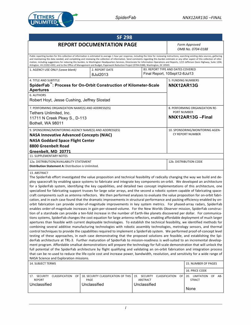
SpiderFab™: Process for On-‐Orbit Construction of Kilometer-‐Scale Apertures
Authors: Robert Hoyt, Jesse Cushing, Jeffrey Slostad
Tethers Unlimited, Inc. 11711 N. Creek Pkwy S., Suite D113 Bothell, WA 98011 Period of Performance: 10 Sept 2012 – 8 July 2013 Final Report
Report Date: 8 July 2013 Grant # NNX12AR13G
Distribution A: Distribution is Unlimited. Sponsored By:
NASA Innovative Advanced Concepts (NIAC) NASA Goddard Space Flight Center 8800 Greenbelt Road Greenbelt, MD 20771
SpiderFab NNX12AR13G –FINAL
i
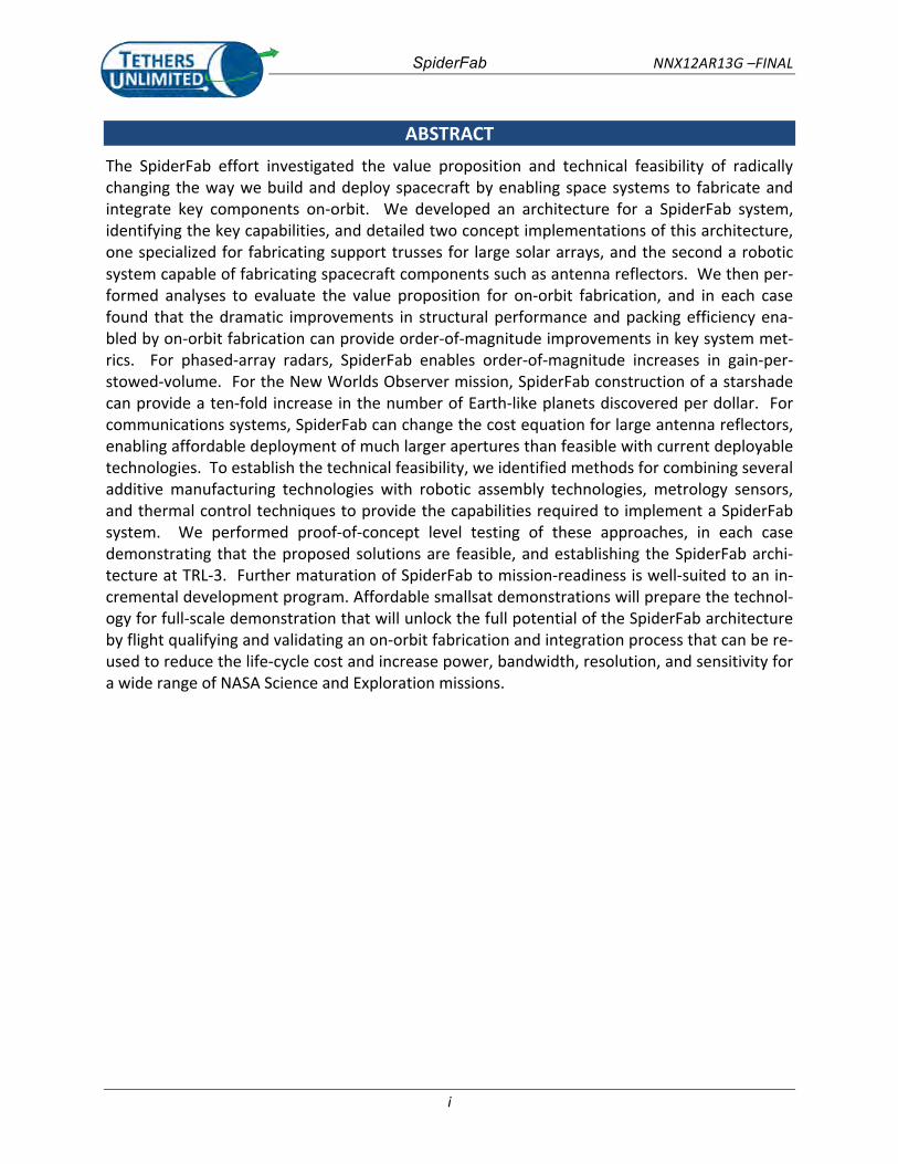
SF 298 REPORT DOCUMENTATION PAGE Form
OMB Approved No. 0704-‐0188
Public reporting burden for this collection of information is estimated to average 1 hour per response, including the time for reviewing instructions, searching existing data sources, gathering and maintaining the data needed, and completing and reviewing the collection of information. Send comments regarding this burden estimate or any other aspect of this collection of infor-‐mation, including suggestions for reducing this burden, to Washington Headquarters Services, Directorate for Information Operations and Reports, 1215 Jefferson Davis Highway, Suite 1204, Arlington, VA 22202-‐4302, and to the Office of Management and Budget, Paperwork Reduction Project (0704-‐0188), Washington, DC 20503.
1. AGENCY USE ONLY (Leave blank) 2. REPORT DATE
8Jul2013 83. REPORT TYPE AND DATES COVERED Final Report, 10Sept12-8Jul13
4. TITLE AND SUBTITLE
SpiderFab™: Process Apertures
for On-Orbit Construction of Kilometer-Scale 5. FUNDING NUMBERS
NNX12AR13G
6. AUTHORS Robert Hoyt, Jesse Cushing, Jeffrey Slostad
7. PERFORMING ORGANIZATION NAME(S) AND
Tethers Unlimited, Inc. 11711 N Creek Pkwy S., D-113 Bothell, WA 98011
ADDRESS(ES) 8. PERFORMING ORGANIZATION PORT NUMBER
NNX12AR13G –Final
RE-‐
9. SPONSORING/MONITORING AGENCY NAME(S) AND ADDRESS(ES)
NASA Innovative Advanced Concepts (NIAC) NASA Goddard Space Flight Center 8800 Greenbelt Road Greenbelt, MD 20771
10. SPONSORING/MONITORING CY REPORT NUMBER
AGEN-‐
11. SUPPLEMENTARY NOTES 12a. DISTRIBUTION/AVAILABILITY STATEMENT Distribution Statement A: Distribution is Unlimited.
12b. DISTRIBUTION CODE
13. ABSTRACT The SpiderFab effort investigated the value proposition and technical feasibility of radically changing the way we build and de-‐ploy spacecraft by enabling space systems to fabricate and integrate key components on-‐orbit. We developed an architecture for a SpiderFab system, identifying the key capabilities, and detailed two concept implementations of this architecture, one specialized for fabricating support trusses for large solar arrays, and the second a robotic system capable of fabricating space-‐craft components such as antenna reflectors. We then performed analyses to evaluate the value proposition for on-‐orbit fabri-‐cation, and in each case found that the dramatic improvements in structural performance and packing efficiency enabled by on-‐orbit fabrication can provide order-‐of-‐magnitude improvements in key system metrics. For phased-‐array radars, SpiderFab enables order-‐of-‐magnitude increases in gain-‐per-‐stowed-‐volume. For the New Worlds Observer mission, SpiderFab construc-‐tion of a starshade can provide a ten-‐fold increase in the number of Earth-‐like planets discovered per dollar. For communica-‐tions systems, SpiderFab changes the cost equation for large antenna reflectors, enabling affordable deployment of much larger apertures than feasible with current deployable technologies. To establish the technical feasibility, we identified methods for combining several additive manufacturing technologies with robotic assembly technologies, metrology sensors, and thermal control techniques to provide the capabilities required to implement a SpiderFab system. We performed proof-‐of-‐concept level testing of these approaches, in each case demonstrating that the proposed solutions are feasible, and establishing the Spi-‐derFab architecture at TRL-‐3. Further maturation of SpiderFab to mission-‐readiness is well-‐suited to an incremental develop-‐ment program. Affordable smallsat demonstrations will prepare the technology for full-‐scale demonstration that will unlock the full potential of the SpiderFab architecture by flight qualifying and validating an on-‐orbit fabrication and integration process that can be re-‐used to reduce the life-‐cycle cost and increase power, bandwidth, resolution, and sensitivity for a wide range of NASA Science and Exploration missions. 14.
SUBJECT TERMS 15. NUMBER OF PAGES 16. PRICE CODE
17. SECURITY REPORT
Unclassified
CLASSIFICATION OF 18. SECURITY CLASSIFICATION PAGE
Unclassified
OF THIS 19. SECURITY ABSTRACT
Unclassified
CLASSIFICATION
OF 20. LIMITATION STRACT
None
OF AB-‐
SpiderFab NNX12AR13G –FINAL
i
ABSTRACT The SpiderFab effort investigated the value proposition and technical feasibility of radically changing the way we build and deploy spacecraft by enabling space systems to fabricate and integrate key components on-‐orbit. We developed an architecture for a SpiderFab system, identifying the key capabilities, and detailed two concept implementations of this architecture, one specialized for fabricating support trusses for large solar arrays, and the second a robotic system capable of fabricating spacecraft components such as antenna reflectors. We then per-‐formed analyses to evaluate the value proposition for on-‐orbit fabrication, and in each case found that the dramatic improvements in structural performance and packing efficiency ena-‐bled by on-‐orbit fabrication can provide order-‐of-‐magnitude improvements in key system met-‐rics. For phased-‐array radars, SpiderFab enables order-‐of-‐magnitude increases in gain-‐per-‐stowed-‐volume. For the New Worlds Observer mission, SpiderFab construction of a starshade can provide a ten-‐fold increase in the number of Earth-‐like planets discovered per dollar. For communications systems, SpiderFab can change the cost equation for large antenna reflectors, enabling affordable deployment of much larger apertures than feasible with current deployable technologies. To establish the technical feasibility, we identified methods for combining several additive manufacturing technologies with robotic assembly technologies, metrology sensors, and thermal control techniques to provide the capabilities required to implement a SpiderFab system. We performed proof-‐of-‐concept level testing of these approaches, in each case demonstrating that the proposed solutions are feasible, and establishing the SpiderFab archi-‐tecture at TRL-‐3. Further maturation of SpiderFab to mission-‐readiness is well-‐suited to an in-‐cremental development program. Affordable smallsat demonstrations will prepare the technol-‐ogy for full-‐scale demonstration that will unlock the full potential of the SpiderFab architecture by flight qualifying and validating an on-‐orbit fabrication and integration process that can be re-‐used to reduce the life-‐cycle cost and increase power, bandwidth, resolution, and sensitivity for a wide range of NASA Science and Exploration missions.
SpiderFab NNX12AR13G –FINAL
ii
TABLE OF CONTENTS SF 298 ................................................................................................................................................... I
ABSTRACT ............................................................................................................................................. I
TABLE OF CONTENTS ............................................................................................................................ II
TA
BLE OF FIGURES ............................................................................................................................... 4
TABLE
1.
OF TABLES ................................................................................................................................. 7
IN
TRODUCTION ............................................................................................................................. 8
1.1 THE CHALLENGE ADDRESSED ................................................................................................................ 8
1.2 THE SPIDERFAB SOLUTION ................................................................................................................... 8
1.3
OVERVIEW OF THE RESULTS OF THE PHASE I EFFORT ................................................................................. 9
2. SP
IDER R2.
FAB A CHITECTURE CONCEPT .......................................................................................... 10
1 THE
SELF-‐FABRICATING SATELLITE ....................................................................................................... 10
2.2 ARCHITECTURE OMPONENTS
C ............................................................................................................. 102.2.1
Material Processing and Suitable Materials .......................................................................... 11
2.2.2
Mobility & Manipulation ....................................................................................................... 12
2.2.3
Assembly & Joining ................................................................................................................ 12
2.
2.4 Thermal Control ..................................................................................................................... 13
2.2.5 Metrology .............................................................................................................................. 13
2.2.6 Integration of Functional Elements ....................................................................................... 13
2.3 IMP
LEMENTATION #1: THE "TRUSSELATOR" FOR ON-‐ORBIT FABRICATION OF SOLAR ARRAY SUPPORT
STRUCTU
RES ............................................................................................................................................. 132.3.1 Background: SOA Deployable Truss Structures for Solar Arrays ........................................... 14
2.3.2 Prior Work on On-‐Orbit Assembly and Fabrication ............................................................... 14
2.3.3 Concept SpiderFab Truss-‐Fabricator for Large Solar Array Deployment ............................... 15
2.4 IMPLEMENTATION #2: THE SPIDERFAB BOT FOR ASSEMBLY OF LARGE APERTURES ...................................... 16
3. VAL
U
E PROPOSITION FOR SPIDERFAB CONSTRUCTION OF SPACE SYSTEMS ................................ 20
3.1 BUILD-‐ON-‐GROUND VS L
. BUI D-‐ON-‐ORBIT ............................................................................................. 20
3.
1.1 Mass Optimization ................................................................................................................ 203.
1.2 Packing Efficiency Improvements .......................................................................................... 21
3.2 RELEVANCE TO NASA TECHNICAL ROADMAP
......................................................................................... 22
3.3 VALUE PROPOSITION FOR SUPPORT STRUCTURES FOR HIGH POWER SOLAR ARRAYS
..................................... 23
3.4 VALUE PROPOSITION FOR PHASED ARRAY ANTENNAS
............................................................................. 24
3.5 VALUE PROPOSITION FOR EXOPLANET IMAGING ..................................................................................... 253.
5.1
Case Study: NWO Starshade .................................................................................................. 25
3.5.2
Net Benefit of SpiderFab for NWO Starshade ........................................................................ 27
3.6
VALUE PROPOSITION FOR LARGE ANTENNA REFLECTORS ......................................................................... 273.6.1 Mass and Volume Estimates ................................................................................................. 29
3.6.2 Fabrication Time .................................................................................................................... 31
3.7
SUMMARY OF THE VALUE PROPOSITION ............................................................................................... 32
4. SPIDERM
4.14.1.14.1.2
4.2 M
FAB TECHNOLOGY FEASIBILITY DEMONSTRATIONS .......................................................... 33ATERIALS AND MATERIAL PROCESSING .............................................................................................. 33Composite Yarn Consolidation and Freeform Shaping to Form Sparse Structures ................ 33Forming of Thermoplastic Prepreg Tape to Create Tubes and Trusses ................................. 35
OBILITY & MANIPULATION .............................................................................................................. 38
SpiderFab NNX12AR13G –FINAL
iii
4.3
ASSEMBLY & JOINING
........................................................................................................................ 394.3.1
Concept for a 'Joiner Spinneret' Using Thermoplastic Bonding ............................................. 404.4 THERMAL
4.
CONTROL .......................................................................................................................... 41
4.1 SpiderFab Material Properties ............................................................................................... 414.4.2 Preheating and Active Cooling .............................................................................................. 41
4.5 M
4.
ETROLOGY .................................................................................................................................... 436 INT
EGRATION OF UNC
F TIONAL ELEMENTS ............................................................................................. 444.6.1
Surface Element Integration .................................................................................................. 44
4.6.2 Attachment of Films .............................................................................................................. 46
4.6.3
Attachment of Conductive Meshes ........................................................................................ 46
4.6.4 Attachment of Rigid Panels ................................................................................................... 47
4.6.5 Installation of Electronic Subassemblies ................................................................................ 47
5. TECHNOLOGY MATURATION PLAN .............................................................................................. 48
6. CONCLUSIONS ............................................................................................................................. 50
REFERENCES ....................................................................................................................................... 51
SpiderFab NNX12AR13G –FINAL
4
TABLE OF FIGURES Figure 1. SpiderFab Value Proposition. On-‐orbit fabrication of spacecraft components enables higher
gain, sensitivity, power, and bandwidth at lower life-‐cycle cost ......................................................... 8Figure 2. Samples fabricated using FFM. On Earth, slumping due to gravity limits the element
dimensions of sparse structures to centimeter scales, but this limit will not be present in microgravity. ..................................................................................................................................... 11
Figure 3. TUI's FFF machine printing a sparse truss structure. ................................................................. 12Figure 4. ISS Solar Wing Assembly. The ISS solar wings use a 33 m long, 1.1 m diameter coilable “FAST
Mast” to deploy and support the solar blankets. The FAST mass has a stowed volume ofappr
oximately 3x1.1 meters. ............................................................................................................ 14
Figure 5. NASA/LaRC Mechanical Joint Concept.2 .................................................................................... 15Figure 6. Prototype Assemble-‐on-‐Orbit Parabolic Tetrahedral Truss Frame at NASA-‐LaRC. ..................... 15
Figure 7. SCAFEDS "Beam Builder" Design Developed by General Dynamics -‐ Convair in 1978. .............. 15
Figure 8. Concept Method for Fabrication of Large, High-‐Performance Truss Structures to Support Solar Arrays. The SpiderFab technology enables on-‐orbit fabrication of large solar array support
structures with order-‐of-‐magnitude improvements in stiffness-‐per-‐mass.
....................................... 16Figure 9. The SpiderFab Bot creates structural elements and adds them to the structure. ..................... 17Figure 10. The SpiderFab Bot uses a 6DOF 3D printing tool to bond structural elements with joints
optimized for the service loads. ........................................................................................................ 17
Figure 11. Concept for a "SpiderFab Bot" constructing a support structure onto a satellite. .................. 18Figure 12. The SpiderFab Bot then applies functional elements, such as reflective membranes, to the
support structure. ............................................................................................................................. 18
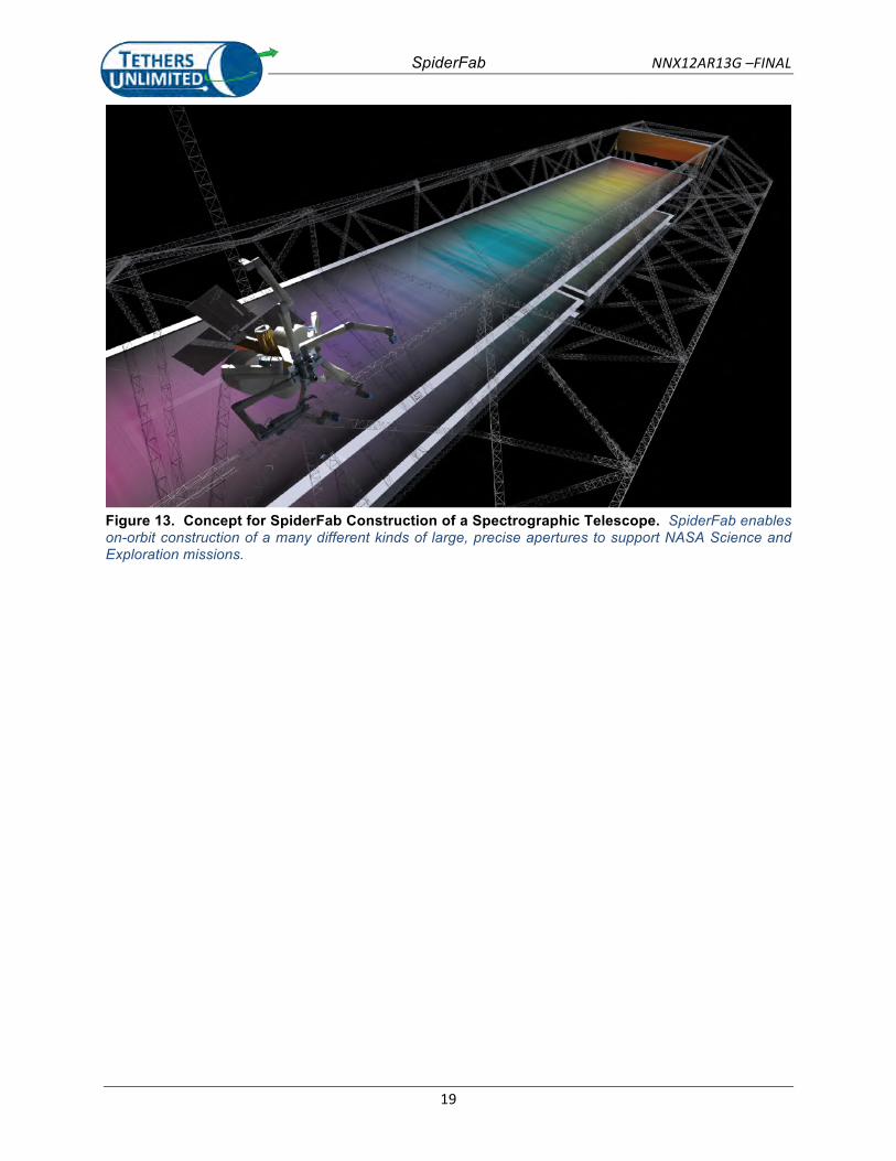
Figure 13. Concept for SpiderFab Construction of a Spectrographic Telescope. SpiderFab enables on-‐orbit construction of a many different kinds of large, precise apertures to support NASA Science andExploration missions.
........................................................................................................................ 19
Figure 14. Truss Packing Efficiency. On-‐orbit fabrication enables packing efficiencies approaching ideal values. (Figure adapted from Mikulas [6]) ....................................................................................... 21
Figure 15. Stowing Efficiency vs. Structural Performance of SOA Deployables and On-‐Orbit Fabricated Structures. On-‐orbit fabrication frees structure designs from the limitations of launch shroud volumes, enabling order of magnitude improvements in structural performance and stowed
volume. ............................................................................................................................................. 23
Figure 16. Phased Array Gain vs. Stowed Volume for SOA Deployables and On-‐Orbit Fabricated
Structures. On-‐orbit fabrication enables decades-‐greater gain from a small stowed volume. ....... 24Figure 17. New Worlds Observer starshade concept. A starshade positioned between a distant star and
a telescope attenuates light from the star to allow the telescope to image planets orbiting that star.
[Images from NWO Final Report, Cash et al.] ................................................................................... 25
Figure 18. Simulation of NWO attenuation of sunlight to enable exoplanet imaging. .............................. 25Figure 19. SOA Deployable NWO Starshade Design. The NWO Starshade design folds up like an umbrella
to fit a 62 m diameter structure within the largest available launch shroud.
[Figures adapted from
NWO final report] ............................................................................................................................. 25
Figure 20. Notional Comparison of Support Structures of the NWO Deployable Starshade and a SpiderFab Starshade. On-‐orbit fabrication enables creation of structures with variable dimensionsand geometries optimized to the operational loads in the microgravity environment.
.................... 26
Figure 21. Size increase achievable with SpiderFab. SpiderFab can enable dramatic increases in aperture size with equal launch mass and significantly smaller stowed volume. ............................................ 26
SpiderFab NNX12AR13G –FINAL
5
Figure 22. Mass and Cost Scaling of Deployable Antenna Reflectors. On-‐orbit fabrication of antenna apertures using SpiderFab can change the cost equation for apertures, enabling deployment of very large apertures at lower cost than conventional deployable technologies. ..................................... 28
Figure 23. SpiderFab Tensegrity Dish Concept. The SpiderFab system will first fabricate a hoop-‐like truss support structure and then attach a reflective membrane and shaping tension lines to the truss. . 29
Figure 24. Variation of antenna reflector component masses with diameter. Antenna diameters of over half a kilometer are feasible within current launch vehicle capabilities. .......................................... 29
Figure 25. Variation of total antenna reflector mass with diameter. SpiderFab enables the mass required for an 'Arecibo in Space' reflector to be well within the capabilities of existing launch vehicles. ..... 30
Figure 26. Variation of required material stowed volume. Packing efficiency improvements provided by SpiderFab enable very large apertures to be launched within reasonable shroud volumes. ............ 31
Figure 27. Fabrication Time as a Function of Antenna Diameter, Single SpiderFab Robot. Fabrication times for even several-‐hundred meter dishes are reasonable with a single robot, and 1/2 to 1 kilometer antennas could be constructed within half a year by 2-‐3 robots.
..................................... 32Figure 28. Principle of operation of the heater die for pultrusion of composite rods using CFRTP yarn as
feedstock. The heater die melts, fuses, and compacts the CFRTP yarn into a stiff structural element.
.......................................................................................................................................................... 33Figure 29. Handheld SpiderFab Pultruder Prototype. We developed and tested manual tools to
understand the requirements of the processes that will later be performed robotically. ................. 34
Figure 30. Samples of composite lattice structures fabricated with the handheld SpiderFab extruder.Pultrusion of CFRTP elements can enable free-‐form fabrication of large, sparse composite structures with excellent structural performance.
............................................................................................. 34Figure 31. First-‐Generation SpiderFab "Trusselator" Process. The SpiderFab process enables material to
be launched as compactly wound yarn and processed on-‐orbit into high-‐performance composite
truss structures. ................................................................................................................................ 35
Figure 32. Roll of Carbon-‐Fiber/PEEK composite tape. CF/PEEK unidirectional prepreg tape can be wound compactly, yet has sufficient stiffness to be fed into a forming mechanism. ........................ 36
Figure 33. Pultrusion/extrusion to transform flexible prepreg tape into high-‐stiffness structural tubes. This test demonstrated that CF/PEEK tape can be processed through a set of heated dies to form high-‐performance structural elements.
............................................................................................ 36Figure 34. Concept Design for a CubeSat-‐Scale Trusselator Mechanism. The patent-‐pending Trusselator
uses a mechanized jig to enable CRFTP yarns to be pultruded in a controlled geometry to form high-‐performance composite truss elements.
........................................................................................... 37Figure 35. Carbon-‐Fiber/PEEK Truss Element. This sample was fabricated manually by wrapping CF/PEEK
rods onto a mandrel in order to evaluate the requirements for automating the process. ............... 37
Figure 36. KRAKEN Robotic Arm. The KRAKEN is a 7DOF robotic arm with 1-‐m reach. Two KRAKEN arms will stow within a 3U CubeSat volume. ............................................................................................. 38
Figure 37. COBRA™ Gimbal Developed for CubeSat Applications. The COBRA gimbal is a Canfield-‐joint carpal-‐wrist mechanism that provides azimuth, elevation, and plunge motions over a full hemispherical work space.
................................................................................................................ 38Figure 38. KRAKEN Arm Engineering Model. TUI has delivered an EM unit to NRL for development of
advanced arm control methods ........................................................................................................ 38
Figure 39. SpiderFab Bot Assembly Process. Local metrology tools, such as stereooptic imagers, guide positioning of the new element relative to the existing structure, and a specialized 'spinneret' tool mounted on one of its arms bonds the element to the structure.
..................................................... 39Figure 40. Conceptual Tube-‐Joining Process Using Fused Filament Fabrication. The SpiderFab Bot uses a
molten-‐material feed head on the joining tool to fashion a joint between the element and theexi
sting structure. ............................................................................................................................. 40
SpiderFab NNX12AR13G –FINAL
6
Figure 41. Prototype 3D-‐Printed Optimized Joint. Use of 3D-‐printing techniques with a highly dexterous print head can enable fabrication of joints optimized for the service loads, maximizing structural efficiency. .......................................................................................................................................... 41
Figure 42. SpiderFab Bot Printing Mounting Feature onto Truss Node. Mounting interface features can be printed onto the joints after completion of the truss structure, which provides another opportunity to compensate for geometry deviations in the placements of the truss members.
...... 41Figure 43. Steady State Thermal Modeling of Solar Heating of the Composite Tube Truss Structure. We
have used CAD-‐based analysis tools to understand the behavior of the ubiquitous curved surfaces and highly anisotropic material properties.
...................................................................................... 42Figure 44. Initial Modelling of In-‐Process Radiative Cooling Patterns. These analyses will guide materials
and joining systems requirements to achieve sufficient fabrication rates and minimize thermal stresses and distortions.
.................................................................................................................... 42Figure 45. Concept for laser pre-‐heating of joint material. Low equilibrium temperatures may
necessitate pre-‐heating of the joint surfaces prior to beginning to deposit onto previously printed parts.
................................................................................................................................................. 43Figure 46. Testing of Plastic Joint Surface Pre-‐Heating with 700mw IR Laser. We have experimented with
non-‐contact methods of heating the joint material to bring cold parts into the processable range. 43
Figure 47. Diagram of Global and Local Metrology. A global metrology system locates the position of the robot within the structure’s coordinate system, and the local metrology measures the shape of the structure near the robot to enable it to accurately position manipulators and fabrication tools.
.... 43Figure 48. Metrology proof-‐of-‐concept demonstration. This simple test validated the feasibility of using
machine vision based metrology to enable closed-‐loop control of fabrication of complex structures.
.......................................................................................................................................................... 44Figure 49. Testing methods for attaching membranes and other components to support structures. We
built tetrahedral truss sections out of pultruded carbon fiber tubes and 3D-‐printed plastic joints, to provide test beds for methods of attaching surface elements.
......................................................... 45Figure 50. Demonstration of Various Functional Surface Elements. Using thermoplastic bonding or
mechanical fasteners in conjunction with 3D-‐printed mounting features, a SpiderFab Bot can mount many types of functional surface elements for various applications.
............................................... 45Figure 51. Concept for Fabricating a Parabolic Reflector. The SpiderFab Bot unrolls a reflective film and
uses its Joiner Spinneret to bond it to the support structure. ........................................................... 46
Figure 52. Example of Conductive Mesh Used for Satellite RF Reflector Dishes. ..................................... 46Figure 53. Left: The SpiderBot using Freeform 3D printing in the microgravity environment to 'weave' a
contoured RF reflector mesh out of conductive filament. Right: spools of copper and nickel coated aramid and carbon fiber. Conductive fibers are joined and rigidized with thermoplastic matrixes to
form custom conductive meshes. ...................................................................................................... 47Figure 54. James Webb Space Telescope Mirror Panels. SpiderFab trusses can provide a thermo-‐
mechanically stable foundation for actively pointed segmented mirrors. ........................................ 47Implementation of the SpiderFab systems is amenable
Figure 55. SpiderFab Capability Maturation Plan. to an incremental development program, with affordable CubeSat and hosted demonstrations building capabilities towards demonstrating construction of large apertures and eventually a fully
self-‐fabricating space system. ........................................................................................................... 48
Figure 56. Concept for initial demonstration of SpiderFab capabilities by fabricating a truss between two
nanosatellites. ................................................................................................................................... 49Figure 57. Concept for demonstration of SpiderFab construction of a large RF aperture as a payload on
an ESPA platform. SpiderFab technology can be validated on affordable secondary payload platforms prior to use in operational missions.
................................................................................. 49

SpiderFab NNX12AR13G –FINAL
7
TABLE OF TABLES Table 1. Relevance of SpiderFab On-‐Orbit Fabrication to NASA Needs and Missions. On-‐orbit fabrication
can enable the large, lightweight systems required to accomplish many future NASA missions. .... 22Table 2. Assumptions Used in Mass, Volume, and Fab Time Estimates for SpiderFab Antennas ............. 30
SpiderFab NNX12AR13G –FINAL
8
SpiderFab provides order-‐of-‐magnitude packing-‐ and mass-‐efficiency improvements for large apertures, enabling higher power, resolution, bandwidth, and sensitivity for space missions at lower lifecycle cost.
1. INTRODUCTION1.1 THE CHALLENGE ADDRESSED The SpiderFab effort has investigated the value proposition and technical feasibility of radically changing the way we build and deploy spacecraft by enabling space systems to fabricate and integrate key com-‐ponents on-‐orbit. Currently, satellites are built and tested on the ground, and then launched aboard rockets. As a result, a large fraction of the engineering cost and launch mass of space systems is required exclusively to ensure the system survives the launch environment. This is particularly true for systems with physically large components, such as antennas, booms, and panels, which must be designed to stow for launch and then deploy reliably on orbit. Furthermore, the performance of space systems are largely determined by the sizes of their apertures, solar panels, and other key components, and the sizes of these structures are limited by the requirement to stow them within available launch fairings. Current State-‐Of-‐the-‐Art (SOA) deployable technologies, such as unfurlable antennas, coilable booms, and de-‐ployable solar panels enable apertures, baselines, and arrays of up to several dozen meters to be stowed within existing launch shrouds. However, the cost of these components increases quickly with increased size, driven by the complexity of the mechanisms required to enable them to fold up within the available volume as well as the testing necessary to ensure they deploy reliably on orbit. As a result, aperture sizes significantly beyond 100 meters are not feasible or affordable with current technologies.
On-‐orbit construction and 'erectables' technologies can enable deployment of space systems larger than can fit in a single launch shroud. The International Space Station is the primary example of a large space system constructed on-‐orbit by assembling multiple components launched separately. Unfortunately, the cost of multiple launches and the astronaut labor required for on-‐orbit construction drive the cost of systems built on the ground and assembled on-‐orbit to scale rapidly with size.
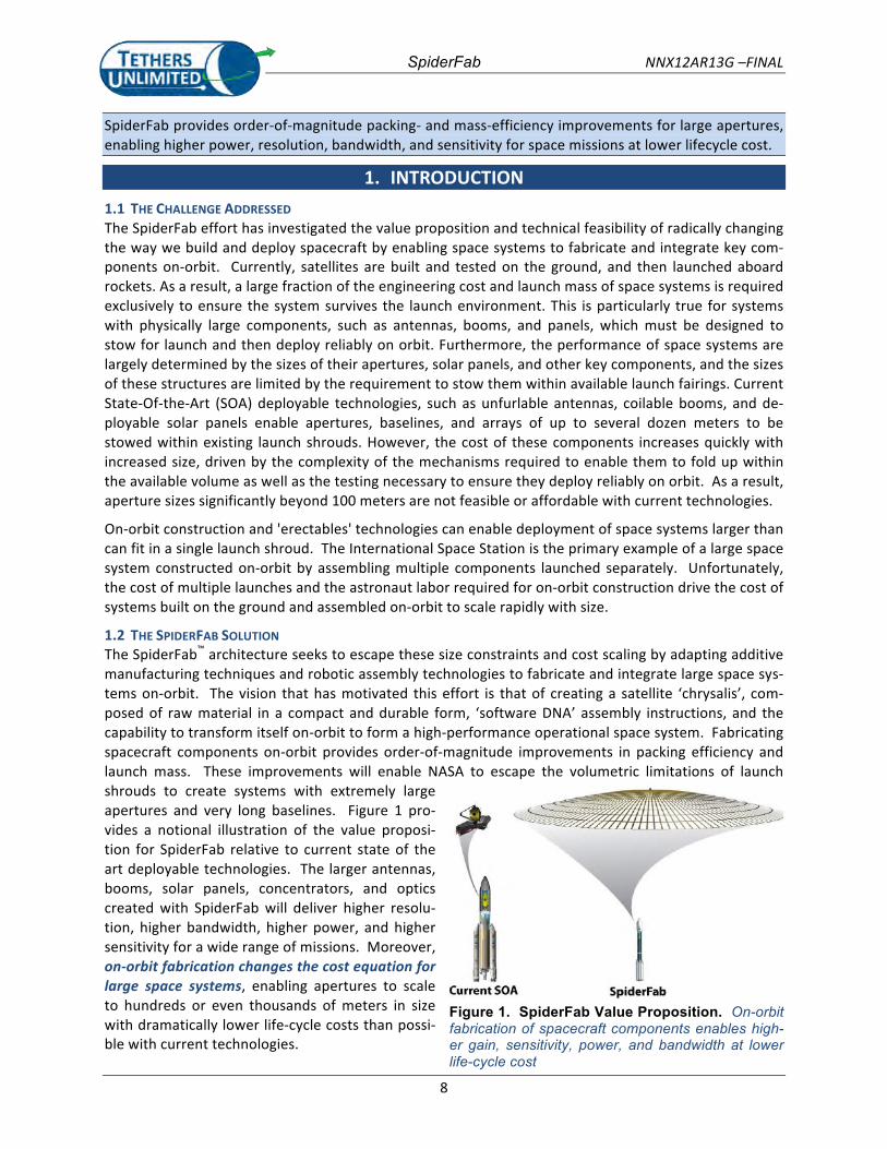
1.2 THE SPIDERFAB SOLUTION The SpiderFab™ architecture seeks to escape these size constraints and cost scaling by adapting additive manufacturing techniques and robotic assembly technologies to fabricate and integrate large space sys-‐tems on-‐orbit. The vision that has motivated this effort is that of creating a satellite ‘chrysalis’, com-‐posed of raw material in a compact and durable form, ‘software DNA’ assembly instructions, and the capability to transform itself on-‐orbit to form a high-‐performance operational space system. Fabricating spacecraft components on-‐orbit provides order-‐of-‐magnitude improvements in packing efficiency and launch mass. These improvements will enable NASA to escape the volumetric limitations of launch shrouds to create systems with extremely large apertures and very long baselines. Figure 1 pro-‐vides a notional illustration of the value proposi-‐tion for SpiderFab relative to current state of the art deployable technologies. The larger antennas, booms, solar panels, concentrators, and optics created with SpiderFab will deliver higher resolu-‐tion, higher bandwidth, higher power, and higher sensitivity for a wide range of missions. Moreover, on-‐orbit fabrication changes the cost equation for large space systems, enabling apertures to scale to hundreds or even thousands of meters in size with dramatically lower life-‐cycle costs than possi-‐ble with current technologies.
Figure 1. SpiderFab Value Proposition. On-orbit fabrication of spacecraft components enables high-er gain, sensitivity, power, and bandwidth at lower life-cycle cost
SpiderFab NNX12AR13G –FINAL
9
1.3 OVERVIEW OF THE RESULTS OF THE PHASE I EFFORT
We began the effort by formulating a concept architecture for a system designed to fabricate and inte-‐grate large spacecraft components on-‐orbit. We call this architecture "SpiderFab" because it involves a robotic system that builds up large, sparse structures in a manner similar to that in which a spider spins its web: by extruding high-‐performance structural elements and assembling them into a larger struc-‐ture. This architecture can be implemented in more than one way, depending upon the application, but in general it requires capabilities for processing material to form structures and components, mobility of fabrication tools and materials, manipulating and joining elements to form a larger structure, and me-‐trology to enable closed-‐loop control of the build process in order to ensure the structure produced meets the requirements to perform its mission function. In Section 2 we will discuss these required ca-‐pabilities and, in order to provide a context for discussion of the value proposition for the SpiderFab ar-‐chitecture, we will present a brief introduction to two concept implementations that use techniques adapted from recent advances in additive manufacturing such as 3D printing and automated fiber layup. The first implementation is a "Trusselator" system for fabricating support structures for solar arrays, and the second is a "SpiderFab Bot" for constructing components such as large antennas and starshades.
To evaluate the value proposition for this method of on-‐orbit fabrication of space systems, we first iden-‐tified NASA technology roadmap needs for large spacecraft components where on-‐orbit fabrication could potentially provide a significant advantage. We then investigated several candidate classes of spacecraft components, including solar arrays, phased array antennas, starshades, and antenna reflec-‐tors, comparing SpiderFab to SOA technologies in terms of key performance metrics. In each case, we found that on-‐orbit fabrication has the potential to enable order-‐of-‐magnitude improvements in these metrics. These Value Proposition analyses will be presented in Section 3.
In order to demonstrate the technical feasibility of implementing these additive manufacturing tech-‐niques to fabricate large spacecraft components, in Section 4 we will further detail concept solutions for each of the capabilities required for a SpiderFab system. Specifically, we developed and tested several methods for taking compactly stowed 'raw' material and processing it into large, sparse, high-‐performance structures. We identified existing robotic manipulator technologies suitable for providing the mobility and manipulation capabilities required. We also investigated several methods for attaching membranes and other solid elements to these structures. These proof-‐of-‐concept level demonstrations validated the fundamental feasibility of the proposed on-‐orbit fabrication architecture.
Finally, we evaluated the technical readiness of the capabilities required to implement a SpiderFab on-‐orbit fabrication system, and developed a plan for maturing the technology to operational use. As de-‐tailed in Section 5, the Phase I effort has matured the SpiderFab concept to a TRL of 3, and significant further work and innovation will be required to implement these techniques in a space-‐capable, auton-‐omous system. Nonetheless, further investment in developing this unconventional approach to deploy-‐ing space systems is warranted because SpiderFab enables orders-‐of-‐magnitude improvements in per-‐formance-‐per-‐cost for a wide range of NASA, DoD, and commercial space missions.
SpiderFab NNX12AR13G –FINAL
10
2. SPIDERFAB ARCHITECTURE CONCEPT On-‐orbit construction has been investigated as a way to deploy large space systems for several decades, but aside from the on-‐orbit assembly of the International Space Station (ISS), which required many launches and many hours of astronaut labor to complete, it has not been used in other operational mis-‐sions because the potential benefits did not outweigh the attendant risks and costs. However, the re-‐cent rapid evolution of additive manufacturing processes such as 3D printing and automated composite layup, as well as the advancement of robotic manipulation and sensing technologies, are creating new opportunities to extend the on-‐orbit construction concept from simply assembly in space to a full in-‐space manufacturing process of fabrication, assembly, and integration. These additive manufacturing technologies can enable space programs to affordably launch material for spacecraft in a very compact and durable form, such as spools of yarn, filament, or tape, tanks of liquid, bags of pellets, or even solid blocks of material, and then process the material on-‐orbit to form multifunctional 3D structures with complex, accurate geometries and excellent structural performance.
These capabilities can enable a radically different approach to developing and deploying spacecraft, one in which we verify, qualify, and launch the process, not the product.
2.1 THE SELF-‐FABRICATING SATELLITE In developing a process for on-‐orbit fabrication of space systems, we have focused upon implementa-‐tions that will enable a space system to create and integrate its own components, so that it is self-‐fabricating. We call this the 'satellite chrysalis' approach, because each space system is launched with the material and tools needed to transform itself on-‐orbit into an operational system. An alternative approach is the 'orbital factory' approach, where a set of fabrication tools are launched to an orbital fa-‐cility, such as the ISS, and this facility uses the same tools repeatedly to produce many space systems. We have chosen to focus upon the more challenging 'chrysalis' approach because although a factory can possibly achieve better economies of scale, launch mass, and reliability through repetition, the econom-‐ics of the factory approach suffer from the transportation costs imposed by orbital dynamics. Specifical-‐ly, the ∆V required to transfer satellites produced at an orbital facility to operational orbits with differ-‐ent inclinations is extremely high, and the resulting launch mass penalty can easily exceed the satellite's mass. As a result, we believe that in the near term, the factory approach will only be competitive in two applications: producing systems that will operate at or near the ISS, and in producing systems in geosta-‐tionary orbit, where transfer ∆V's are relatively small. A self-‐fabricating capability that is economically competitive with conventional technologies will be competitive in any orbit. Moreover, the capabilities required for a factory are a subset of those required for a self-‐fabricating system, so if we can successful-‐ly implement a self-‐fabricating 'satellite chrysalis', then implementing an orbital satellite factory will be straightforward.
In Section 3 we will investigate the value proposition for this unconventional approach to building space systems. In order to provide a context for that evaluation, in this section we will first discuss the funda-‐mental capability components required to implement an on-‐orbit fabrication and integration architec-‐ture, and we will then briefly summarize two concept implementations of such an architecture.
2.2 ARCHITECTURE COMPONENTS The SpiderFab architecture for on-‐orbit fabrication of spacecraft components will require (1) Techniques for Processing Suitable Materials to create structures, (2) Mechanisms for Mobility and Manipulation of Tools and Materials, (3) Methods for Assembly and Joining of Structures, (4) Methods for Thermal Con-‐trol of Materials and Structures, (5) Metrology to enable closed-‐loop control of the fabrication process, and (6) Methods for Integrating Functional Elements onto structures built on-‐orbit.
SpiderFab NNX12AR13G –FINAL
11
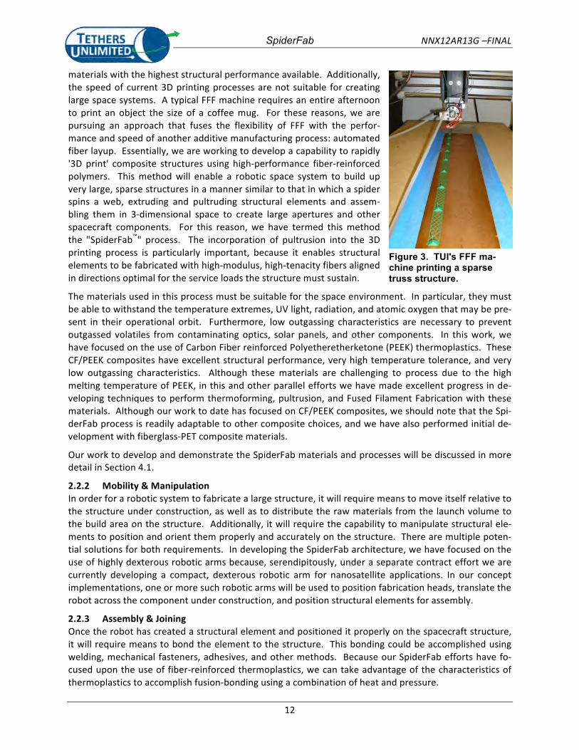
2.2.1 Material Processing and Suitable Materials The self-‐fabricating satellite will require a capability to process raw material launched in a compact state into high-‐performance, multifunctional structures. Additive manufacturing processes such as Fused Fil-‐ament Fabrication (FFF, also known under the trademark of Fused Deposition Modeling, or FDM®), Se-‐lective Laser Sintering (SLS), Electron Beam Melting, and Electron Beam Free-‐Form Fabrication (EBF3) are highly advantageous for this capability because they enable raw materials in the form of pellets, powders, or ribbons of filament to be melted and re-‐formed to build up complex 3D geometries layer by layer, with little or no wasted material. Figure 3 shows a photo of one of our developmental FFF ma-‐chines printing a small sparse truss structure.
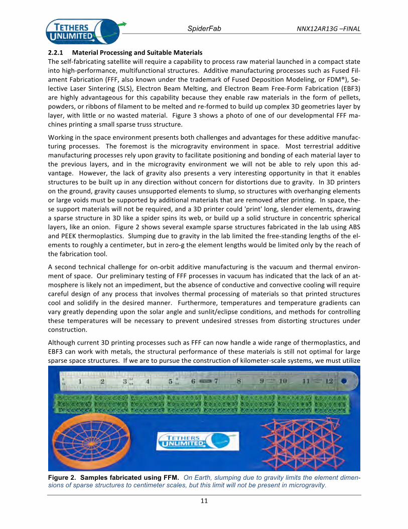
Working in the space environment presents both challenges and advantages for these additive manufac-‐turing processes. The foremost is the microgravity environment in space. Most terrestrial additive manufacturing processes rely upon gravity to facilitate positioning and bonding of each material layer to the previous layers, and in the microgravity environment we will not be able to rely upon this ad-‐vantage. However, the lack of gravity also presents a very interesting opportunity in that it enables structures to be built up in any direction without concern for distortions due to gravity. In 3D printers on the ground, gravity causes unsupported elements to slump, so structures with overhanging elements or large voids must be supported by additional materials that are removed after printing. In space, the-‐se support materials will not be required, and a 3D printer could 'print' long, slender elements, drawing a sparse structure in 3D like a spider spins its web, or build up a solid structure in concentric spherical layers, like an onion. Figure 2 shows several example sparse structures fabricated in the lab using ABS and PEEK thermoplastics. Slumping due to gravity in the lab limited the free-‐standing lengths of the el-‐ements to roughly a centimeter, but in zero-‐g the element lengths would be limited only by the reach of the fabrication tool.
A second technical challenge for on-‐orbit additive manufacturing is the vacuum and thermal environ-‐ment of space. Our preliminary testing of FFF processes in vacuum has indicated that the lack of an at-‐mosphere is likely not an impediment, but the absence of conductive and convective cooling will require careful design of any process that involves thermal processing of materials so that printed structures cool and solidify in the desired manner. Furthermore, temperatures and temperature gradients can vary greatly depending upon the solar angle and sunlit/eclipse conditions, and methods for controlling these temperatures will be necessary to prevent undesired stresses from distorting structures under construction.
Although current 3D printing processes such as FFF can now handle a wide range of thermoplastics, and EBF3 can work with metals, the structural performance of these materials is still not optimal for large sparse space structures. If we are to pursue the construction of kilometer-‐scale systems, we must utilize
Figure 2. Samples fabricated using FFM. On Earth, slumping due to gravity limits the element dimen-sions of sparse structures to centimeter scales, but this limit will not be present in microgravity.
SpiderFab NNX12AR13G –FINAL
12
materials with the highest structural performance available. Additionally, the speed of current 3D printing processes are not suitable for creating large space systems. A typical FFF machine requires an entire afternoon to print an object the size of a coffee mug. For these reasons, we are pursuing an approach that fuses the flexibility of FFF with the perfor-‐mance and speed of another additive manufacturing process: automated fiber layup. Essentially, we are working to develop a capability to rapidly '3D print' composite structures using high-‐performance fiber-‐reinforced polymers. This method will enable a robotic space system to build up very large, sparse structures in a manner similar to that in which a spider spins a web, extruding and pultruding structural elements and assem-‐bling them in 3-‐dimensional space to create large apertures and other spacecraft components. For this reason, we have termed this method the "SpiderFab™" process. The incorporation of pultrusion into the 3D printing process is particularly important, because it enables structural elements to be fabricated with high-‐modulus, high-‐tenacity fibers aligned in directions optimal for the service loads the structure must sustain.
Figure 3. TUI's FFF ma-chine printing a sparse truss structure.
The materials used in this process must be suitable for the space environment. In particular, they must be able to withstand the temperature extremes, UV light, radiation, and atomic oxygen that may be pre-‐sent in their operational orbit. Furthermore, low outgassing characteristics are necessary to prevent outgassed volatiles from contaminating optics, solar panels, and other components. In this work, we have focused on the use of Carbon Fiber reinforced Polyetheretherketone (PEEK) thermoplastics. These CF/PEEK composites have excellent structural performance, very high temperature tolerance, and very low outgassing characteristics. Although these materials are challenging to process due to the high melting temperature of PEEK, in this and other parallel efforts we have made excellent progress in de-‐veloping techniques to perform thermoforming, pultrusion, and Fused Filament Fabrication with these materials. Although our work to date has focused on CF/PEEK composites, we should note that the Spi-‐derFab process is readily adaptable to other composite choices, and we have also performed initial de-‐velopment with fiberglass-‐PET composite materials.
Our work to develop and demonstrate the SpiderFab materials and processes will be discussed in more detail in Section 4.1.
2.2.2 Mobility & Manipulation In order for a robotic system to fabricate a large structure, it will require means to move itself relative to the structure under construction, as well as to distribute the raw materials from the launch volume to the build area on the structure. Additionally, it will require the capability to manipulate structural ele-‐ments to position and orient them properly and accurately on the structure. There are multiple poten-‐tial solutions for both requirements. In developing the SpiderFab architecture, we have focused on the use of highly dexterous robotic arms because, serendipitously, under a separate contract effort we are currently developing a compact, dexterous robotic arm for nanosatellite applications. In our concept implementations, one or more such robotic arms will be used to position fabrication heads, translate the robot across the component under construction, and position structural elements for assembly.
2.2.3 Assembly & Joining Once the robot has created a structural element and positioned it properly on the spacecraft structure, it will require means to bond the element to the structure. This bonding could be accomplished using welding, mechanical fasteners, adhesives, and other methods. Because our SpiderFab efforts have fo-‐cused upon the use of fiber-‐reinforced thermoplastics, we can take advantage of the characteristics of thermoplastics to accomplish fusion-‐bonding using a combination of heat and pressure.
SpiderFab NNX12AR13G –FINAL
13
2.2.4 Thermal Control A significant challenge for fabricating precise structural elements, managing structural stresses in the elements, and reliably forming fusion bonds between the elements will be managing the temperature of the materials in the space environment, where both mean temperatures and temperature gradient vec-‐tors can vary dramatically depending upon the direction to the sun and the position in orbit. In the Spi-‐derFab implementations we propose to use additives or coatings in the fiber-‐reinforced thermoplastics to cold-‐bias the materials and minimize their thermal fluctuations under different insolation conditions, and use contact, radiative, and/or microwave heating to form and bond these materials.
2.2.5 Metrology Automated or tele-‐robotic systems for constructing large components will require capabilities for accu-‐rately measuring the component as it is built. This metrology will be needed at two scales: macro-‐scale metrology, to measure the overall shape of the component to ensure it meets system requirements, and micro-‐scale metrology, to enable accurate location of material feed heads with respect to the local fea-‐tures of the structure under construction. Technologies currently in use in terrestrial manufacturing processes, such as structured-‐light scanning and stereo-‐imaging, can be adapted to provide these func-‐tionalities.
2.2.6 Integration of Functional Elements Once the SpiderFab system has created a base structure, it will also require methods and mechanisms to integrate functional elements such as reflective membranes, antenna panels, solar cells, sensors, wiring, and payload packages into or onto the support structure. Because most of these components can be packaged very compactly, and require high precision in manufacture and assembly, in the near term it is likely to be most effective to fabricate these components on the ground and integrate them on-‐orbit. In the long-‐term, it may be possible to implement additive manufacturing methods capable of processing many materials so that some of these components could be fabricated in-‐situ, but nonetheless it will only be advantageous to do so if on-‐orbit fabrication provides a significant improvement in launch mass or performance. The techniques for automated integration of functional elements onto a space struc-‐ture will depend upon the nature of the element. Reflective membranes and solar cells can be delivered to orbit in compact rolls or folded blankets and unrolled onto a structure using thermal bonding, adhe-‐sives, or mechanical fasteners to affix them to the structure. Sensors, payloads, and avionics boxes can be integrated onto the structure using mechanical fasteners. Wiring can be unspooled and clipped or bonded to the structure, and attached to payload elements using quick-‐connect plugs.
2.3 IMPLEMENTATION #1: THE "TRUSSELATOR" FOR ON-‐ORBIT FABRICATION OF SOLAR ARRAY SUPPORT STRUCTURES Of the candidate applications for the SpiderFab on-‐orbit fabrication architecture, large solar arrays are likely the most straightforward and near-‐term application. Future robotic and manned exploration mis-‐sions to Mars and the outer planets could be enabled by high-‐power solar electric propulsion systems, but the 300kW+ power levels desired for these systems will be very challenging and expensive to supply using current solar array technologies. NASA has a goal of achieving specific power performance of ≥120 W/kg to enable these large arrays to be affordable to launch.1 On-‐orbit fabrication and assembly of large solar arrays could enable the cost and mass reductions required to make such ambitious mis-‐sions feasible. In this initial effort, we have developed a concept approach for using on-‐orbit fabrication and integration to deploy large solar arrays. This initial effort resulted in a proposal to topic H5.01, "Ex-‐pandable/Deployable Structures", in NASA's 2012 SBIR program, and on 23 May 2013, NASA's SBIR pro-‐gram awarded TUI a Phase I contract to pursue application of the SpiderFab approach to enable on-‐orbit fabrication of support structures for large solar arrays. This SBIR contract represents a successful transi-‐tion of SpiderFab to post-‐NIAC NASA programs.
SpiderFab NNX12AR13G –FINAL
14
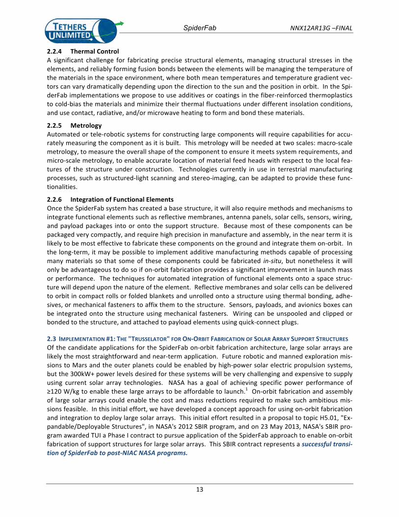
2.3.1 Background: SOA Deployable Truss Structures for Solar Arrays The 2012 NASA Strategic Space Technology Investment Plan has identified high-‐power (300 kW) solar electric propulsion (SEP) as a key technology for enhancement of human exploration missions, and also identified Lightweight Space Structures and Materials as a key technology for reducing mission launch mass and life-‐cycle cost. The current state-‐of-‐the-‐art (SOA) in high-‐power solar arrays and their associ-‐ated support structures is represented by the ISS solar wing assemblies. As illustrated in Figure 4, the ISS solar wings are composed of two foldable solar cell blankets that are deployed and supported by a “Folding Articulated Square Truss” (FAST) Mast. The mast provides structural stiffness both to tension the flexible solar blanket as well as to support and orient it as the spacecraft changes orientations and the system slews to track the sun. The FAST Mast has a deployed length of 108 ft. (33m), and has a square cross section 30.4” on a side. Stowed, the coilable FAST Mast consumes a volume approximately 1.1 meters in diameter and nearly 3 meters in length. Each solar wing assembly generates approximately 10 kW. To supply 300 kW for a SEP mission with this technology would require roughly 90 cubic meters of stowed volume for the trusses alone, or approximately 3 Falcon-‐9 launches just for the support struc-‐ture.
Figure 4. ISS Solar Wing Assembly. The ISS solar wings use a 33 m long, 1.1 m diameter coilable “FAST Mast” to deploy and support the solar blankets. The FAST mass has a stowed volume of approx-imately 3x1.1 meters.
The FAST Mast is one of the highest performance space deployables on orbit. Nevertheless, when stowed, a very large portion of the stowed volume is ‘empty’, and thus there is opportunity for dramatic improvement in stowed volume. Taking advantage of that opportunity, however, will require a dramati-‐cally different approach to designing and deploying the structure. Additionally, because the structural stiffness-‐per-‐mass of a truss structure increases with the square of the truss diameter, there is a strong benefit to using larger diameter trusses. The diameter of deployable truss technologies, however, is limited by the volume available within a launch shroud, and the FAST Mast approaches that limit. Taking better advantage of the geometric scaling of truss structural performance, therefore, will also require a dramatically different approach to creating the structure.
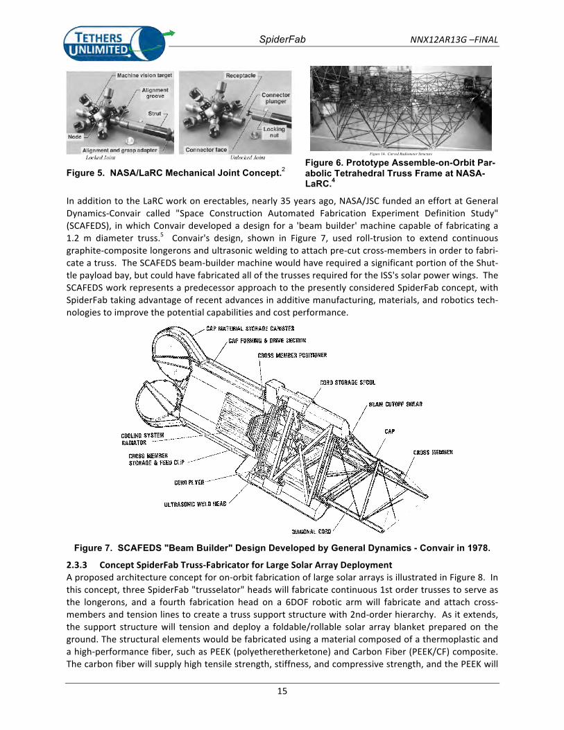
2.3.2 Prior Work on On-‐Orbit Assembly and Fabrication Beyond the current SOA deployables, NASA/LaRC has made significant progress in the development of techniques for assembly of truss-‐based structures on-‐orbit.2,3 This “erectables” approach involves launching pre-‐fabricated strut components and using astronaut labor or telerobotic systems to connect them together to form truss support structures for large-‐aperture telescopes. Figure 5 shows examples of prototype components developed by the LaRC efforts, and Figure 6 show a large truss frame for a parabolic reflector assembled in the lab using this erectable technology. Erectable structures can pack-‐age the component pieces of a space structure more efficiently than deployable systems, but this ap-‐proach has not yet been validated on a mission scale.
SpiderFab NNX12AR13G –FINAL
15
Figure 5. NASA/LaRC Mechanical Joint Concept.2
Figure 14. Curved Radiometer Structure
Figure 6. Prototype Assemble-on-Orbit Par-abolic Tetrahedral Truss Frame at NASA-LaRC.4
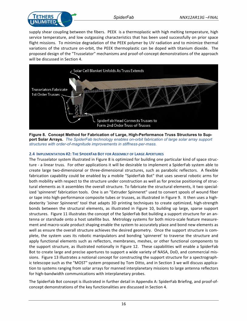
In addition to the LaRC work on erectables, nearly 35 years ago, NASA/JSC funded an effort at General Dynamics-‐Convair called "Space Construction Automated Fabrication Experiment Definition Study" (SCAFEDS), in which Convair developed a design for a 'beam builder' machine capable of fabricating a 1.2 m diameter truss.5 Convair's design, shown in Figure 7, used roll-‐trusion to extend continuous graphite-‐composite longerons and ultrasonic welding to attach pre-‐cut cross-‐members in order to fabri-‐cate a truss. The SCAFEDS beam-‐builder machine would have required a significant portion of the Shut-‐tle payload bay, but could have fabricated all of the trusses required for the ISS's solar power wings. The SCAFEDS work represents a predecessor approach to the presently considered SpiderFab concept, with SpiderFab taking advantage of recent advances in additive manufacturing, materials, and robotics tech-‐nologies to improve the potential capabilities and cost performance.
CAP IWATEMIJAL S?ORAOE CAMSTEW
CAP FLWWG 8 n m SECTION
CROSS MEMBER PffSlnORER
CRQSS MEMBER STORAGE 8 FE%O CLIP
WLTRASQYIG WfbB HEWD
Figure 7. SCAFEDS "Beam Builder" Design Developed by General Dynamics - Convair in 1978.
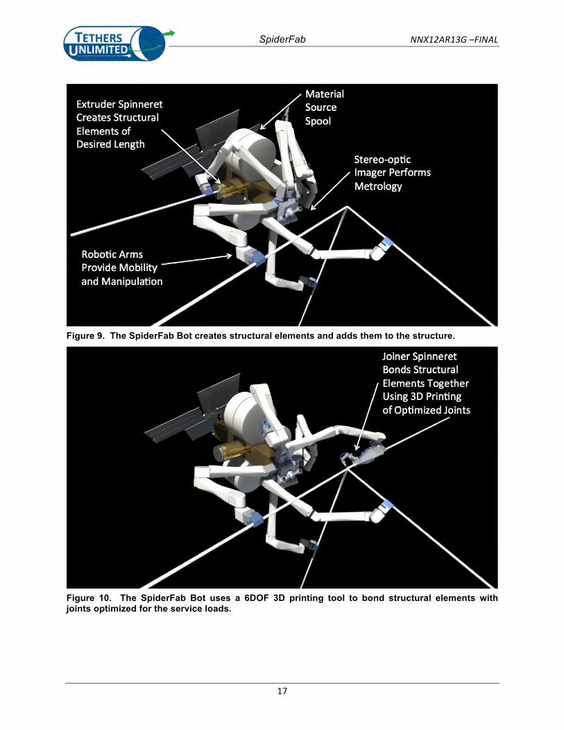
2.3.3 Concept SpiderFab Truss-‐Fabricator for Large Solar Array Deployment A proposed architecture concept for on-‐orbit fabrication of large solar arrays is illustrated in Figure 8. In this concept, three SpiderFab "trusselator" heads will fabricate continuous 1st order trusses to serve as the longerons, and a fourth fabrication head on a 6DOF robotic arm will fabricate and attach cross-‐members and tension lines to create a truss support structure with 2nd-‐order hierarchy. As it extends, the support structure will tension and deploy a foldable/rollable solar array blanket prepared on the ground. The structural elements would be fabricated using a material composed of a thermoplastic and a high-‐performance fiber, such as PEEK (polyetheretherketone) and Carbon Fiber (PEEK/CF) composite. The carbon fiber will supply high tensile strength, stiffness, and compressive strength, and the PEEK will
SpiderFab NNX12AR13G –FINAL
16
supply shear coupling between the fibers. PEEK is a thermoplastic with high melting temperature, high service temperature, and low outgassing characteristics that has been used successfully on prior space flight missions. To minimize degradation of the PEEK polymer by UV radiation and to minimize thermal variations of the structure on-‐orbit, the PEEK thermoplastic can be doped with titanium dioxide. The proposed design of the "Trusselator" mechanisms and proof-‐of-‐concept demonstrations of the approach will be discussed in Section 4.
Figure 8. Concept Method for Fabrication of Large, High-Performance Truss Structures to Sup-port Solar Arrays. The SpiderFab technology enables on-orbit fabrication of large solar array support structures with order-of-magnitude improvements in stiffness-per-mass.
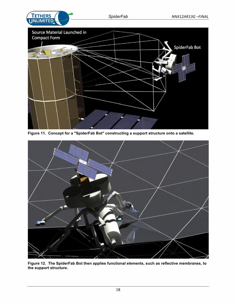
2.4 IMPLEMENTATION #2: THE SPIDERFAB BOT FOR ASSEMBLY OF LARGE APERTURES The Trusselator system illustrated in Figure 8 is optimized for building one particular kind of space struc-‐ture -‐ a linear truss. For other applications it will be desirable to implement a SpiderFab system able to create large two-‐dimensional or three-‐dimensional structures, such as parabolic reflectors. A flexible fabrication capability could be enabled by a mobile "SpiderFab Bot" that uses several robotic arms for both mobility with respect to the structure under construction as well as for precise positioning of struc-‐tural elements as it assembles the overall structure. To fabricate the structural elements, it two special-‐ized 'spinneret' fabrication tools. One is an "Extruder Spinneret" used to convert spools of wound fiber or tape into high-‐performance composite tubes or trusses, as illustrated in Figure 9. It then uses a high-‐dexterity 'Joiner Spinneret' tool that adapts 3D printing techniques to create optimized, high-‐strength bonds between the structural elements, as illustrated in Figure 10, building up large, sparse support structures. Figure 11 illustrates the concept of the SpiderFab Bot building a support structure for an an-‐tenna or starshade onto a host satellite bus. Metrology systems for both micro-‐scale feature measure-‐ment and macro-‐scale product shaping enable the system to accurately place and bond new elements as well as ensure the overall structure achieves the desired geometry. Once the support structure is com-‐plete, the system uses its robotic manipulators and bonding 'spinneret' to traverse the structure and apply functional elements such as reflectors, membranes, meshes, or other functional components to the support structure, as illustrated notionally in Figure 12. These capabilities will enable a SpiderFab Bot to create large and precise apertures to support a wide variety of NASA, DoD, and commercial mis-‐sions. Figure 13 illustrates a notional concept for constructing the support structure for a spectrograph-‐ic telescope such as the "MOST" system proposed by Tom Ditto, and in Section 3 we will discuss applica-‐tion to systems ranging from solar arrays for manned interplanetary missions to large antenna reflectors for high-‐bandwidth communications with interplanetary probes.
The SpiderFab Bot concept is illustrated in further detail in Appendix A: SpiderFab Briefing, and proof-‐of-‐concept demonstrations of the key functionalities are discussed in Section 4.
SpiderFab NNX12AR13G –FINAL
17
Figure 9. The SpiderFab Bot creates structural elements and adds them to the structure.
Figure 10. The SpiderFab Bot uses a 6DOF 3D printing tool to bond structural elements with joints optimized for the service loads.
SpiderFab NNX12AR13G –FINAL
18
Figure 11. Concept for a "SpiderFab Bot" constructing a support structure onto a satellite.
Figure 12. The SpiderFab Bot then applies functional elements, such as reflective membranes, to the support structure.
SpiderFab NNX12AR13G –FINAL
19
Figure 13. Concept for SpiderFab Construction of a Spectrographic Telescope. SpiderFab enables on-orbit construction of a many different kinds of large, precise apertures to support NASA Science and Exploration missions.
SpiderFab NNX12AR13G -FINAL
20
3. VALUE PROPOSITION FOR SPIDERFAB CONSTRUCTION OF SPACE SYSTEMSTo evaluate the value proposition for on-orbit fabrication of space systems using the SpiderFab architec-ture, we first considered the trade-offs between building components on the ground versus buildingthem on orbit, and identified two key advantages that on-orbit fabrication can provide. We then re-viewed NASA’s Technology Roadmaps to identify Technology Areas and future NASA missions whereSpiderFab could provide significant advantages. Then, we considered four of these technology compo-nents, and developed performance metrics to quantify the potentail advantages that SpiderFab couldprovide.
3.1 BUILD-ON- GROUND VS. BUILD-ON-ORBITOn-orbit fabrication of a space system can free the system design from the volumetric constraints oflaunch vehicles and reduce the mass and engineering costs associated with designing the system to sur-vive launch. However, these advantages must be traded against the additional cost and complexity ofenabling these components to be fabricated and integrated in an automated manner in the space envi-ronment. Furthermore, whereas in the conventional approach components are fabricated, integrated,and tested prior to launch, a program using on-orbit fabrication must commit and expend the costs as-sociated with launch before these parts are created and integrated. Consequently, although our far-term goal is to enable fabrication and integration of essentially all of a spacecraft on-orbit, we must ap-proach this goal incrementally, and focus initial investment on classes of components where our currenttechnology capabilities can provide a significant net benefit. Satellites and other spacecraft are typicallycomposed of a number of subcomponents, ranging from bulk structures to actuated mechanisms tocomplex microelectrics. All of these components could, in theory, be fabricated on-orbit, but invest-ing in developing the capability to do so can only be justified if on-orbit fabrication can provide a dra-matic net improvement in performance-per-cost. On-orbit fabrication can provide benefits primarily intwo ways: launch mass reductions, and parking efficiency improvements.
3.1.1 Mass OptimizationFabricating a space structure on-orbit can reduce system mass because the design of structural compo-nents can be optimized for the microgravity loads they must sustain in the space environment, not forthe 100’s of gravities shock and vibrations they would experience during launch. Additionally, largestructures built on-orbit do not require the hinges, latches, and other complex mechanisms needed bydeployable structures, reducing the ‘parasitic’ mass of the structure and enabling it to be fully optimizedfor its design loads. Building a structure on-orbit, rather than designing it for deployment, also enablesits geometry to be varied and/or tapered in an optimal manner throughout the structure, which for verylarge structures supporting well-defined loads can result in significant mass savings. Furthermore, it en-ables creation of structures with cross-sections that would be too large to fit in a launch shroud, taking advantage of geometric optimizations that can provide large improvements in structural performance.For example, the bending stiffness of a longeron truss increases as the square of its effective diameterD:
EIm
18
EρΣ
D2 ,= (1)
where ρ is the material mass density, m is the mass per unit length of the beam, E is the material modu-lus, and Σ is a constant accounting for battens, cross members, and joints.6 Whereas a deployable trussdesigned to stow within a launch shroud will typically have a maximum diameter on the order of a me-ter, trusses fabricated on orbit can readily be built with diameters of several meters or more, providingan order of magnitude improvement in stiffness per mass.
SpiderFab NNX12AR13G –FINAL
21
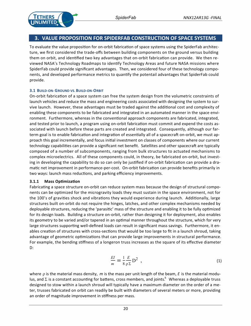
3.1.2 Packing Efficiency Improvements The second manner in which on-‐orbit fabrication can enable significant improvements is the packing efficiency of large components. Figure 14, adapted from Reference [6], compares the packing efficiency of deployable trusses (flown) and erectable trusses (proposed). Existing deployable technologies fall one to two orders of magnitude short of ideal packing efficiency (ie -‐ 95% to 99% of their stowed volume is "wasted"). Proposed erectable technologies, in which individual structural elements such as longe-‐rons and struts are launched in tightly packed bundles and then assembled on-‐orbit to fabricate large sparse structures, may be able to improve the packing efficiency somewhat, 'wasting' only about 90% of their stowed volume. On-‐orbit fabrication with the SpiderFab process, which uses materials that can be launched as tightly wound spools of yarn, tape, or filament, as pellets, or even as solid blocks of feed-‐stock, can enable packing efficiencies approaching unity. Figure 14 notes the regime we project Spi-‐derFab on-‐orbit fabrication can enable space trusses to achieve -‐ diameters of multiple meters to take advantage of the geometric advantages expressed in Eqn (1), and reducing wasted launch volume down to 50%-‐10%. This improvement in packing efficiency will be particularly advantageous for components that are by nature very large, sparse, and/or gossamer, such as antennas, trusses, shrouds, and reflec-‐tors.
Graphite/Epoxy.Coilable.
=.1.Perfect.Packaging.Efficiency.
Fiberglass.Coilable.
Figure 14. Truss Packing Efficiency. On-orbit fabrication enables packing efficiencies approaching ideal values. (Figure adapted from Mikulas [6])

SpiderFab NNX12AR13G –FINAL
22
3.2 RELEVANCE TO NASA TECHNICAL ROADMAP With the parameters that SpiderFab will be most advantageous for space systems that require very large, sparse, or gossamer components, we reviewed the 2012 NASA Technology Roadmaps and identi-‐fied a number of technology areas where on-‐orbit fabrication with SpiderFab could provide the size and/or performance improvements required to enable future missions NASA has identified as high prior-‐ity. Table 1 summarizes the results of this review, and demonstrates that SpiderFab has strong rele-‐vance across a wide range of NASA Science and Exploration missions.
Table 1. Relevance of SpiderFab On-Orbit Fabrication to NASA Needs and Missions. On-orbit fab-rication can enable the large, lightweight systems required to accomplish many future NASA missions.
Technology Area Example Mission/Program Need Reference
Starshade (occulter) 30-‐100m, 0.1m shape accuracy
New Worlds Observer 2012 TA08 Roadmap: SIOSS, Table 7
Large Deployable Anten-‐nas
10-‐14m 20 Gbps from
1AU
SWOT, ONEP, ACE, SCLP Mars-‐28, Mars 30
2012 TA08 Roadmap: SIOSS, Table 3 2012 TA05 Roadmap: Com-‐munications and Navigation Systems, Table 7
Deployable Boom/Mast 20-‐500m Structure-‐Connected Sparse Aperture; TPF-‐I; SPECS
2012 TA08 Roadmap: SIOSS, Fig 4
High Power Solar Array 30-‐300kW 0.5-‐1 kW/kg HEOMD Solar-‐EP Missions
2012 NASA Strategic Space Technology Investment Plan; 2012 TA03 Roadmap: Space Power and Energy Storage
Radiators multi-‐MW HEOMD Nuclear-‐Electric Missions Solar Sail Space Demo, In-‐terstellar Probe
2012 TA14 Roadmap: Ther-‐mal Management Systems
Large Solar Sail >1000 m2 1 g/m2
2012 TA02 Roadmap: In Space Propulsion; 2.2.2
Solar Concentrator 85-‐90% con-‐centrator efficiency
LEO Cargo Tug; LEO-‐GEO Tug;
2012 TA02 Roadmap: In Space Propulsion; 2.2.3
2012 TA08 Roadmap: SIOSS, Table 7 Large Aperture Telescope 50m2 aper-‐
ture Extremely Large Space Tele-‐scope (EL-‐ST), TPF-‐C
SpiderFab NNX12AR13G –FINAL
23
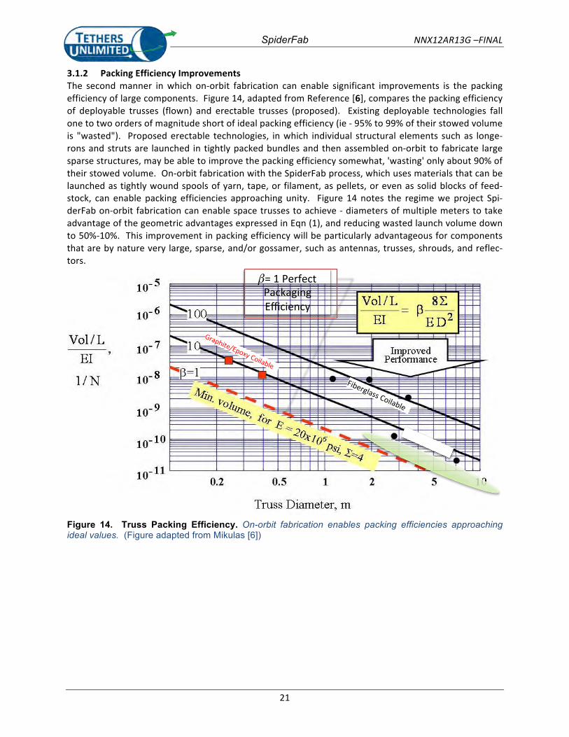
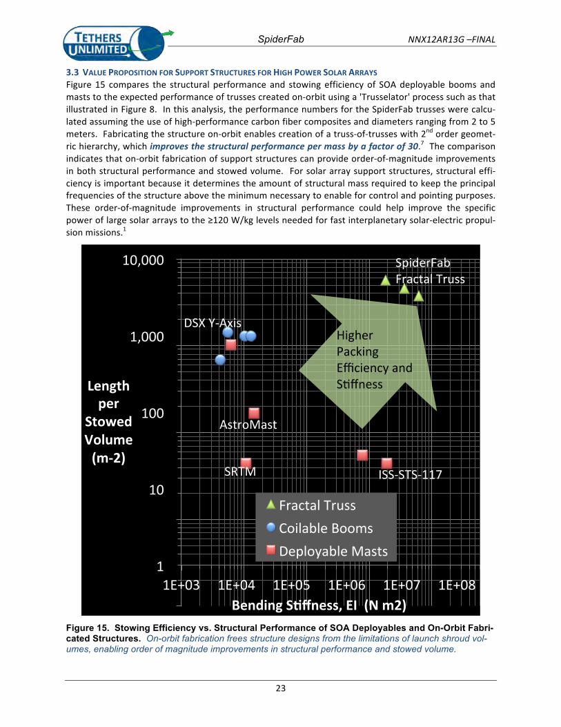
3.3 VALUE PROPOSITION FOR SUPPORT STRUCTURES FOR HIGH POWER SOLAR ARRAYS Figure 15 compares the structural performance and stowing efficiency of SOA deployable booms and masts to the expected performance of trusses created on-‐orbit using a 'Trusselator' process such as that illustrated in Figure 8. In this analysis, the performance numbers for the SpiderFab trusses were calcu-‐lated assuming the use of high-‐performance carbon fiber composites and diameters ranging from 2 to 5 meters. Fabricating the structure on-‐orbit enables creation of a truss-‐of-‐trusses with 2nd order geomet-‐ric hierarchy, which improves the structural performance per mass by a factor of 30.7 The comparison indicates that on-‐orbit fabrication of support structures can provide order-‐of-‐magnitude improvements in both structural performance and stowed volume. For solar array support structures, structural effi-‐ciency is important because it determines the amount of structural mass required to keep the principal frequencies of the structure above the minimum necessary to enable for control and pointing purposes. These order-‐of-‐magnitude improvements in structural performance could help improve the specific power of large solar arrays to the ≥120 W/kg levels needed for fast interplanetary solar-‐electric propul-‐sion missions.1
!1!!
!10!!
!100!!
!1,000!!
!10,000!!
1E+03! 1E+04! 1E+05! 1E+06! 1E+07! 1E+08!
Length''per''
Stowed'Volume'(m32)'
Bending'S8ffness,'EI''(N'm2)'
Fractal!Truss!Coilable!Booms!Deployable!Masts!
SRTM%
AstroMast%
DSX%Y/Axis%
ISS/STS/117%
Higher%Packing%Efficiency%and%SAffness%
SpiderFab%Fractal%Truss%
Figure 15. Stowing Efficiency vs. Structural Performance of SOA Deployables and On-Orbit Fabri-cated Structures. On-orbit fabrication frees structure designs from the limitations of launch shroud vol-umes, enabling order of magnitude improvements in structural performance and stowed volume.
SpiderFab NNX12AR13G -FINAL
24
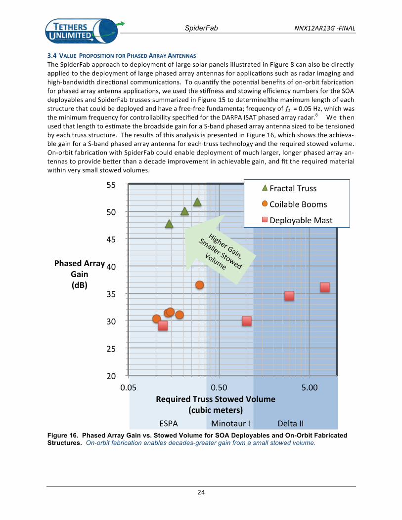
3.4 VALUE PROPOSITION FOR PHASED ARRAY ANTENNASThe SpiderFab approach to deployment of large solar panels illustrated in Figure 8 can also be directlyapplied to the deployment of large phased array antennas for applications such as radar imaging andhigh-bandwidth directional communications. To quantify the potential benefits of on-orbit fabricationfor phased array antenna applications, we used the stiffness and stowing efficiency numbers for the SOAdeployables and SpiderFab trusses summarized in Figure 15 to determine the maximum length of e! achstructure that could be deployed and have a free-free fundamenta; frequency of f1 = 0.05 Hz, which wasthe minimum frequency for controllability specified for the DARPA ISAT phased array radar.8 We thenused that length to estimate the broadside gain for a S-band phased array antenna sized to be tensionedby each truss structure. The results of this analysis is presented in Figure 16, which shows the achieva-ble gain for a S-band phased array antenna for each truss technology and the required stowed volume.On-orbit fabrication with SpiderFab could enable deployment of much larger, longer phased array an-tennas to provide better than a decade improvement in achievable gain, and fit the required materialwithin very small stowed volumes.
20
25
30
35
40
45
50
55
0.05 0.50 5.00
Phased ArrayGain(dB)
Required Truss Stowed Volume(cubic meters)
Fractal Truss
Coilable Booms
Deployable Mast
ESPA Minotaur I Delta II
Higher Gain,
Smaller StowedVolume
Figure 16. Phased Array Gain vs. Stowed Volume for SOA Deployables and On-Orbit Fabricated Structures. On-orbit fabrication enables decades-greater gain from a small stowed volume.
SpiderFab NNX12AR13G -FINAL
25
3.5 VALUE PROPOSITION FOR EXOPLANET IMAGING
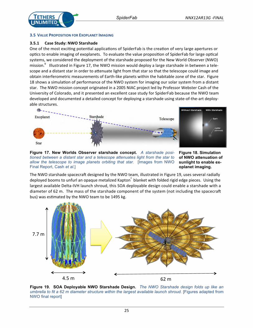
3.5.1 Case Study: NWO StarshadeOne of the most exciting potential applications of SpiderFab is the creation of very large apertures oroptics to enable imaging of exoplanets. To evaluate the value proposition of SpiderFab for large opticalsystems, we considered the deployment of the starshade proposed for the New World Observer (NWO)mission.9 Illustrated in Figure 17, the NWO mission would deploy a large starshade in between a tele-scope and a distant star in order to attenuate light from that star so that the telescope could image andobtain interferometric measurements of Earth-like planets within the habitable zone of the star. Figure18 shows a simulation of performance of the NWO system for imaging our solar system from a distantstar. The NWO mission concept originated in a 2005 NIAC project led by Professor Webster Cash of theUniversity of Colorado, and it presented an excellent case study for SpiderFab because the NWO teamdeveloped and documented a detailed concept for deploying a starshade using state-of-the-art deploy-able structures.
Figure 17. New Worlds Observer starshade concept. A starshade posi-tioned between a distant star and a telescope attenuates light from the star to allow the telescope to image planets orbiting that star. [Images from NWO Final Report, Cash et al.]
Figure 18. Simulation of NWO attenuation of sunlight to enable ex-oplanet imaging.
The NWO starshade spacecraft designed by the NWO team, illustrated in Figure 19, uses several radiallydeployed booms to unfurl an opaque metalized Kapton® blanket with folded rigid edge pieces. Using thelargest available Delta-IVH launch shroud, this SOA deployable design could enable a starshade with adiameter of 62 m. The mass of the starshade component of the system (not including the spacecraftbus) was estimated by the NWO team to be 1495 kg.
4.5 m
7.7 m
62 mFigure 19. SOA Deployable NWO Starshade Design. The NWO Starshade design folds up like an umbrella to fit a 62 m diameter structure within the largest available launch shroud. [Figures adapted from NWO final report]
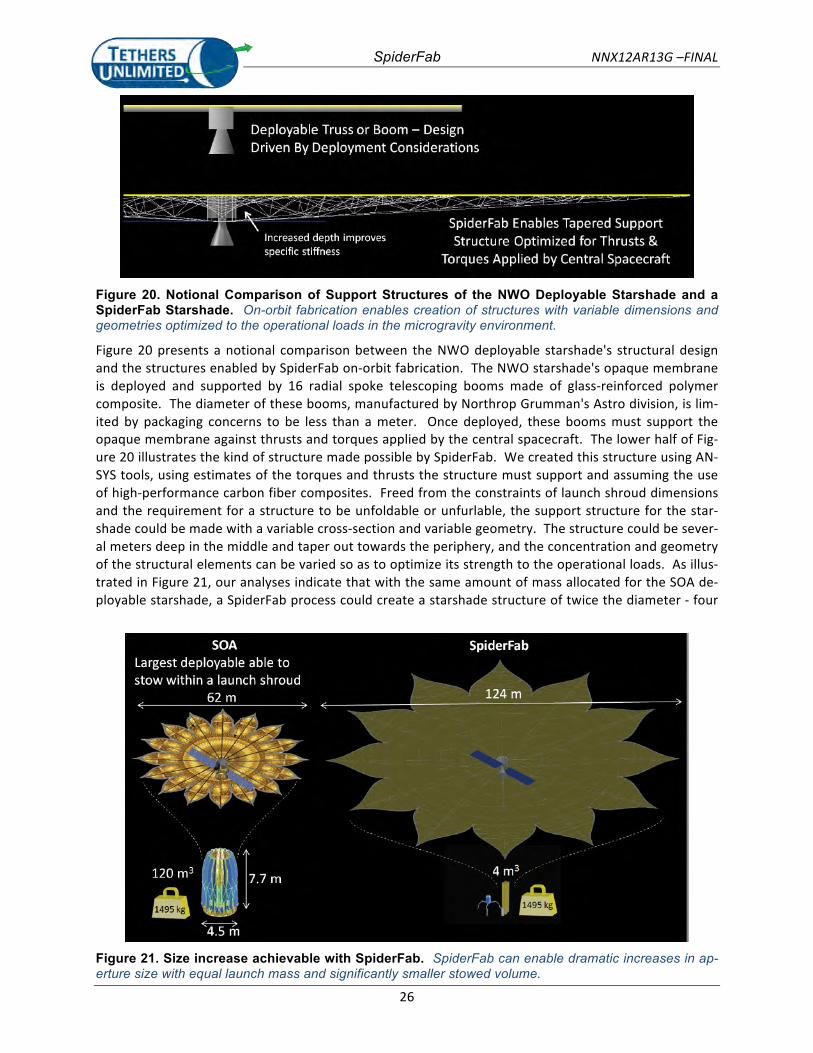
SpiderFab NNX12AR13G –FINAL
26
Figure 20. Notional Comparison of Support Structures of the NWO Deployable Starshade and a SpiderFab Starshade. On-orbit fabrication enables creation of structures with variable dimensions and geometries optimized to the operational loads in the microgravity environment.
Figure 20 presents a notional comparison between the NWO deployable starshade's structural design and the structures enabled by SpiderFab on-‐orbit fabrication. The NWO starshade's opaque membrane is deployed and supported by 16 radial spoke telescoping booms made of glass-‐reinforced polymer composite. The diameter of these booms, manufactured by Northrop Grumman's Astro division, is lim-‐ited by packaging concerns to be less than a meter. Once deployed, these booms must support the opaque membrane against thrusts and torques applied by the central spacecraft. The lower half of Fig-‐ure 20 illustrates the kind of structure made possible by SpiderFab. We created this structure using AN-‐SYS tools, using estimates of the torques and thrusts the structure must support and assuming the use of high-‐performance carbon fiber composites. Freed from the constraints of launch shroud dimensions and the requirement for a structure to be unfoldable or unfurlable, the support structure for the star-‐shade could be made with a variable cross-‐section and variable geometry. The structure could be sever-‐al meters deep in the middle and taper out towards the periphery, and the concentration and geometry of the structural elements can be varied so as to optimize its strength to the operational loads. As illus-‐trated in Figure 21, our analyses indicate that with the same amount of mass allocated for the SOA de-‐ployable starshade, a SpiderFab process could create a starshade structure of twice the diameter -‐ four
Figure 21. Size increase achievable with SpiderFab. SpiderFab can enable dramatic increases in ap-erture size with equal launch mass and significantly smaller stowed volume.
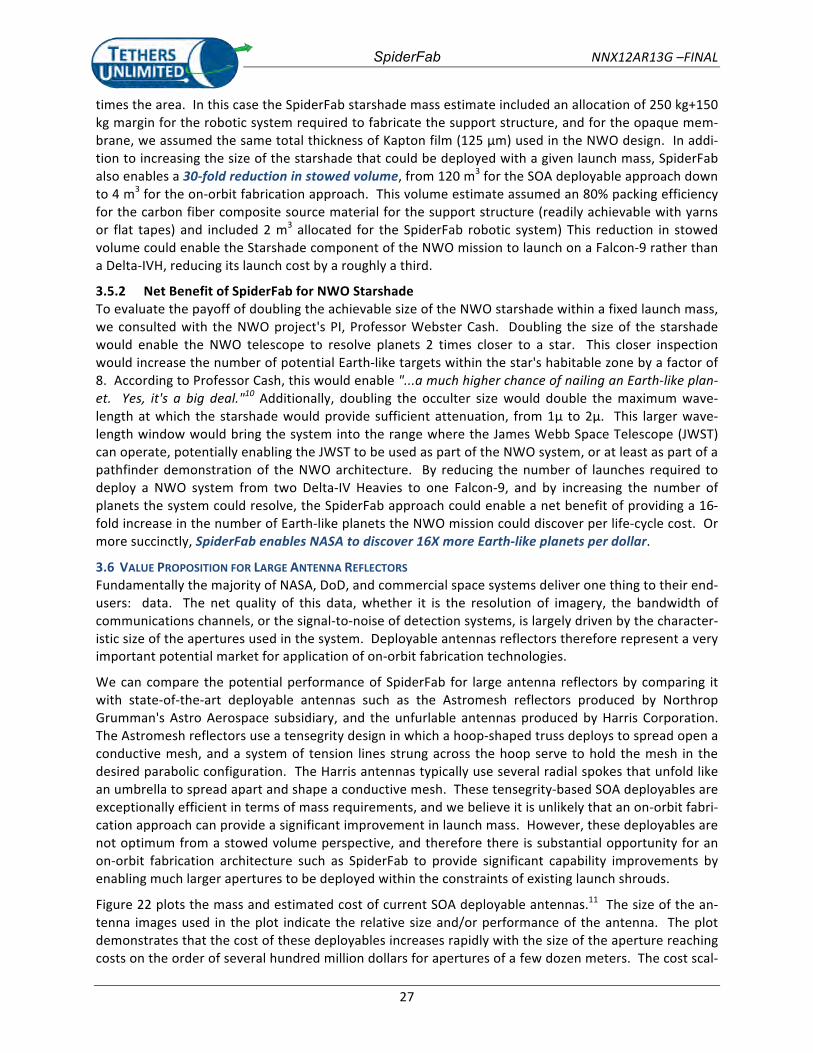
SpiderFab NNX12AR13G –FINAL
27
times the area. In this case the SpiderFab starshade mass estimate included an allocation of 250 kg+150 kg margin for the robotic system required to fabricate the support structure, and for the opaque mem-‐brane, we assumed the same total thickness of Kapton film (125 µm) used in the NWO design. In addi-‐tion to increasing the size of the starshade that could be deployed with a given launch mass, SpiderFab also enables a 30-‐fold reduction in stowed volume, from 120 m3 for the SOA deployable approach down to 4 m3 for the on-‐orbit fabrication approach. This volume estimate assumed an 80% packing efficiency for the carbon fiber composite source material for the support structure (readily achievable with yarns or flat tapes) and included 2 m3 allocated for the SpiderFab robotic system) This reduction in stowed volume could enable the Starshade component of the NWO mission to launch on a Falcon-‐9 rather than a Delta-‐IVH, reducing its launch cost by a roughly a third.
3.5.2 Net Benefit of SpiderFab for NWO Starshade To evaluate the payoff of doubling the achievable size of the NWO starshade within a fixed launch mass, we consulted with the NWO project's PI, Professor Webster Cash. Doubling the size of the starshade would enable the NWO telescope to resolve planets 2 times closer to a star. This closer inspection would increase the number of potential Earth-‐like targets within the star's habitable zone by a factor of 8. According to Professor Cash, this would enable "...a much higher chance of nailing an Earth-‐like plan-‐et. Yes, it's a big deal."10 Additionally, doubling the occulter size would double the maximum wave-‐length at which the starshade would provide sufficient attenuation, from 1µ to 2µ. This larger wave-‐length window would bring the system into the range where the James Webb Space Telescope (JWST) can operate, potentially enabling the JWST to be used as part of the NWO system, or at least as part of a pathfinder demonstration of the NWO architecture. By reducing the number of launches required to deploy a NWO system from two Delta-‐IV Heavies to one Falcon-‐9, and by increasing the number of planets the system could resolve, the SpiderFab approach could enable a net benefit of providing a 16-‐fold increase in the number of Earth-‐like planets the NWO mission could discover per life-‐cycle cost. Or more succinctly, SpiderFab enables NASA to discover 16X more Earth-‐like planets per dollar.
3.6 VALUE PROPOSITION FOR LARGE ANTENNA REFLECTORS Fundamentally the majority of NASA, DoD, and commercial space systems deliver one thing to their end-‐users: data. The net quality of this data, whether it is the resolution of imagery, the bandwidth of communications channels, or the signal-‐to-‐noise of detection systems, is largely driven by the character-‐istic size of the apertures used in the system. Deployable antennas reflectors therefore represent a very important potential market for application of on-‐orbit fabrication technologies.
We can compare the potential performance of SpiderFab for large antenna reflectors by comparing it with state-‐of-‐the-‐art deployable antennas such as the Astromesh reflectors produced by Northrop Grumman's Astro Aerospace subsidiary, and the unfurlable antennas produced by Harris Corporation. The Astromesh reflectors use a tensegrity design in which a hoop-‐shaped truss deploys to spread open a conductive mesh, and a system of tension lines strung across the hoop serve to hold the mesh in the desired parabolic configuration. The Harris antennas typically use several radial spokes that unfold like an umbrella to spread apart and shape a conductive mesh. These tensegrity-‐based SOA deployables are exceptionally efficient in terms of mass requirements, and we believe it is unlikely that an on-‐orbit fabri-‐cation approach can provide a significant improvement in launch mass. However, these deployables are not optimum from a stowed volume perspective, and therefore there is substantial opportunity for an on-‐orbit fabrication architecture such as SpiderFab to provide significant capability improvements by enabling much larger apertures to be deployed within the constraints of existing launch shrouds.
Figure 22 plots the mass and estimated cost of current SOA deployable antennas.11 The size of the an-‐tenna images used in the plot indicate the relative size and/or performance of the antenna. The plot demonstrates that the cost of these deployables increases rapidly with the size of the aperture reaching costs on the order of several hundred million dollars for apertures of a few dozen meters. The cost scal-‐
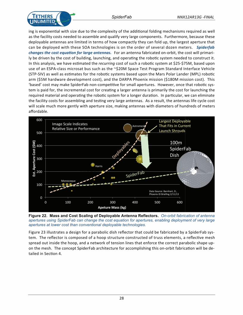
SpiderFab NNX12AR13G -FINAL
28
ing is exponential with size due to the complexity of the additional folding mechanisms required as wellas the facility costs needed to assemble and qualify very large components. Furthermore, because thesedeployable antennas are limited in terms of how compactly they can fold up, the largest aperture thatcan be deployed with these SOA technologies is on the order of several dozen meters. Spiderfabchanges the cost equation for large antennas. For an antenna fabricated on-orbit, the cost will primari-ly be driven by the cost of building, launching, and operating the robotic system needed to construct it.In this analysis, we have estimated the recurring cost of such a robotic system at $25-$75M, based uponuse of an ESPA-class microsat bus such as the ~$20M Space Test Program Standard Interface Vehicle(STP-SIV) as well as estimates for the robotic systems based upon the Mars Polar Lander (MPL) roboticarm ($5M hardware development cost), and the DARPA Phoenix mission ($180M mission cost). This‘based’ cost may make SpiderFab non-competitive for small apertures. However, once that robotic sys-tem is paid for, the incremental cost for creating a larger antenna is primarily the cost for launching therequired material and operating the robotic system for a longer duration. In particular, we can eliminatethe facility costs for assembling and testing very large antennas. As a result, the antennas life cycle costwill scale much more gently with aperture size, making antennas with diameters of hundreds of metersaffordable.
0
100
200
300
400
500
600
0 100 200 300 400 500 600
Est.
Aper
ture
Cos
t ($M
)
Apeture Mass (kg)
Data Source: Barnhart, D.,Phoenix ID Briefing 2/11/13
Astromesh
Harris
Monocoque
Image Scale IndicatesRelative Size or Performance
100mSpiderFabDish
SpiderFab
Largest DeployableThat Fits in CurrentLaunch Shrouds
Figure 22. Mass and Cost Scaling of Deployable Antenna Reflectors. On-orbit fabrication of antenna apertures using SpiderFab can change the cost equation for apertures, enabling deployment of very large apertures at lower cost than conventional deployable technologies.
Figure 23 illustrates a design for a parabolic dish reflector that could be fabricated by a SpiderFab sys-tem. The reflector is composed of a hoop structure constructed of truss elements, a reflective meshspread out inside the hoop, and a network of tension lines that enforce the correct parabolic shape up-on the mesh. The concept SpiderFab architecture for accomplishing this on-orbit fabrication will be de-tailed in Section 4.
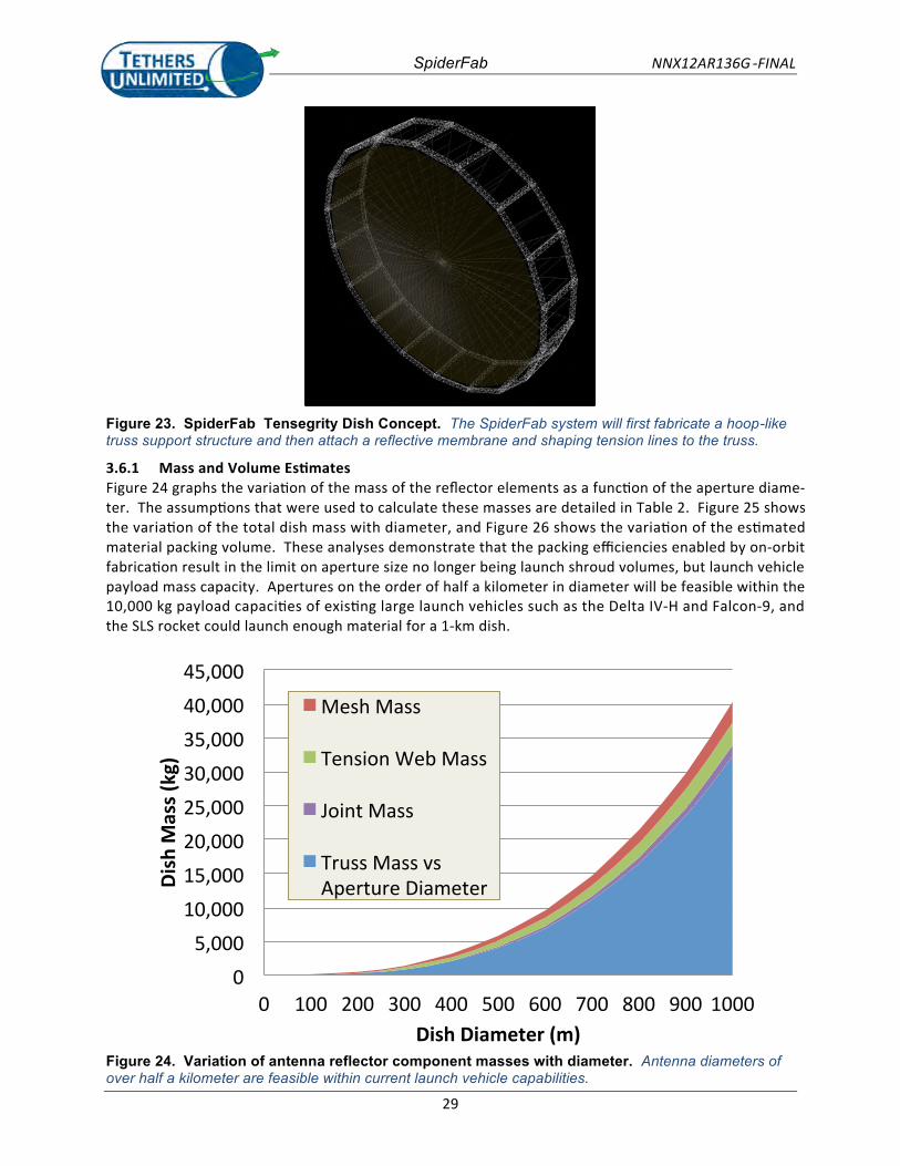
SpiderFab NNX12AR136G -FINAL
29
Figure 23. SpiderFab Tensegrity Dish Concept. The SpiderFab system will first fabricate a hoop-like truss support structure and then attach a reflective membrane and shaping tension lines to the truss.
3.6.1 Mass and Volume EstimatesFigure 24 graphs the variation of the mass of the reflector elements as a function of the aperture diame-ter. The assumptions that were used to calculate these masses are detailed in Table 2. Figure 25 showsthe variation of the total dish mass with diameter, and Figure 26 shows the variation of the estimatedmaterial packing volume. These analyses demonstrate that the packing efficiencies enabled by on-orbitfabrication result in the limit on aperture size no longer being launch shroud volumes, but launch vehiclepayload mass capacity. Apertures on the order of half a kilometer in diameter will be feasible within the10,000 kg payload capacities of existing large launch vehicles such as the Delta IV-H and Falcon-9, andthe SLS rocket could launch enough material for a 1-km dish.
05,000
10,00015,00020,00025,00030,00035,00040,00045,000
0 100 200 300 400 500 600 700 800 900 1000
Dish
Mas
s (kg
)
Dish Diameter (m)
Mesh Mass
Tension Web Mass
Joint Mass
Truss Mass vsAperture Diameter
Figure 24. Variation of antenna reflector component masses with diameter. Antenna diameters of over half a kilometer are feasible within current launch vehicle capabilities.
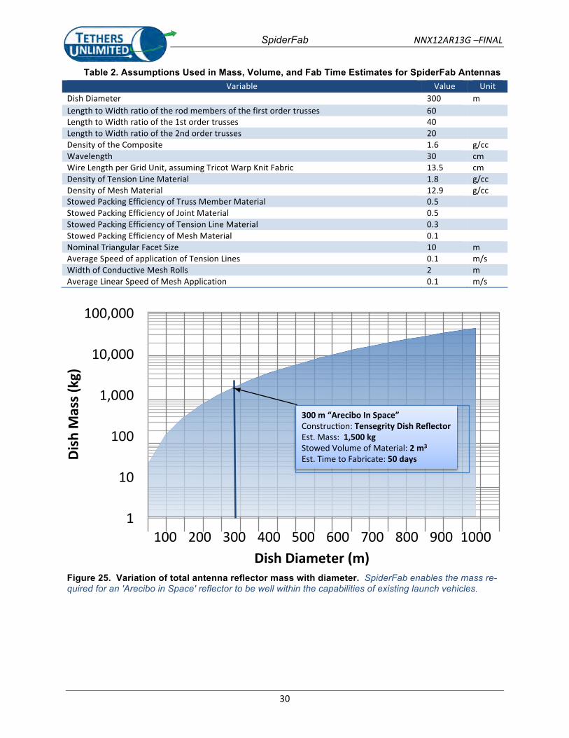
SpiderFab NNX12AR13G –FINAL
30
Table 2. Assumptions Used in Mass, Volume, and Fab Time Estimates for SpiderFab Antennas Variable Value Unit
Dish Diameter 300 m Length to Width ratio of the rod members of the first order trusses 60
Length to Width ratio of the 1st order trusses 40 Length to Width ratio of the 2nd order trusses 20 Density of the Composite 1.6 g/cc Wavelength 30 cm Wire Length per Grid Unit, assuming Tricot Warp Knit Fabric 13.5 cm Density of Tension Line Material 1.8 g/cc Density of Mesh Material 12.9 g/cc Stowed Packing Efficiency of Truss Member Material 0.5
Stowed Packing Efficiency of Joint Material 0.5 Stowed Packing Efficiency of Tension Line Material 0.3 Stowed Packing Efficiency of Mesh Material 0.1 Nominal Triangular Facet Size 10 m Average Speed of application of Tension Lines 0.1 m/s Width of Conductive Mesh Rolls 2 m Average Linear Speed of Mesh Application 0.1 m/s
1"
10"
100"
1,000"
10,000"
100,000"
100" 200" 300" 400" 500" 600" 700" 800" 900" 1000"
Dish%M
ass%(kg)%
Dish%Diameter%(m)%
300#m#“Arecibo#In#Space”##Construc)on:+Tensegrity#Dish#Reflector#Est.+Mass:++1,500#kg#Stowed+Volume+of+Material:#2#m3#
Est.+Time+to+Fabricate:+50#days#
Figure 25. Variation of total antenna reflector mass with diameter. SpiderFab enables the mass re-quired for an 'Arecibo in Space' reflector to be well within the capabilities of existing launch vehicles.
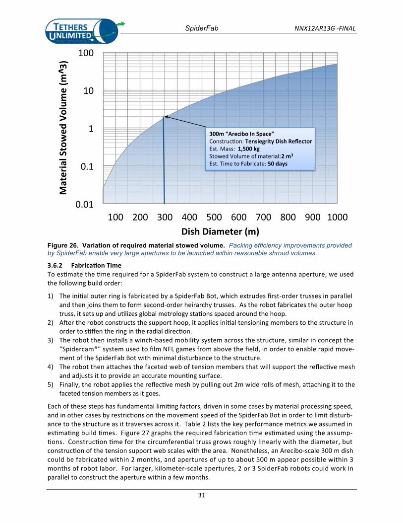
SpiderFab NNX12AR13G -FINAL
31
Figure 26. Variation of required material stowed volume. Packing efficiency improvements provided by SpiderFab enable very large apertures to be launched within reasonable shroud volumes.
3.6.2 Fabrication TimeTo estimate the time required for a SpiderFab system to construct a large antenna aperture, we usedthe following build order:
1) The initial outer ring is fabricated by a SpiderFab Bot, which extrudes first-order trusses in paralleland then joins them to form second-order heirarchy trusses. As the robot fabricates the outer hooptruss, it sets up and utilizes global metrology stations spaced around the hoop.
2) After the robot constructs the support hoop, it applies initial tensioning members to the structure inorder to stiffen the ring in the radial direction.
3) The robot then installs a winch-based mobility system across the structure, similar in concept the“Spidercam®” system used to film NFL games from above the field, in order to enable rapid move-ment of the SpiderFab Bot with minimal disturbance to the structure.
4) The robot then attaches the faceted web of tension members that will support the reflective meshand adjusts it to provide an accurate mounting surface.
5) Finally, the robot applies the reflective mesh by pulling out 2m wide rolls of mesh, attaching it to thefaceted tension members as it goes.
Each of these steps has fundamental limiting factors, driven in some cases by material processing speed,and in other cases by restrictions on the movement speed of the SpiderFab Bot in order to limit disturb-ance to the structure as it traverses across it. Table 2 lists the key performance metrics we assumed inestimating build times. Figure 27 graphs the required fabrication time estimated using the assump-tions. Construction time for the circumferential truss grows roughly linearly with the diameter, butconstruction of the tension support web scales with the area. Nonetheless, an Arecibo-scale 300 m dishcould be fabricated within 2 months, and apertures of up to about 500 m appear possible within 3months of robot labor. For larger, kilometer-scale apertures, 2 or 3 SpiderFab robots could work inparallel to construct the aperture within a few months.
0.01
0.1
1
10
100
100 200 300 400 500 600 700 800 900 1000Dish Diameter (m)
300m “Arecibo In Space”Construction: Tensiegrity Dish ReflectorEst. Mass: 1,500 kgStowed Volume of material:2 m3
Est. Time to Fabricate: 50 days
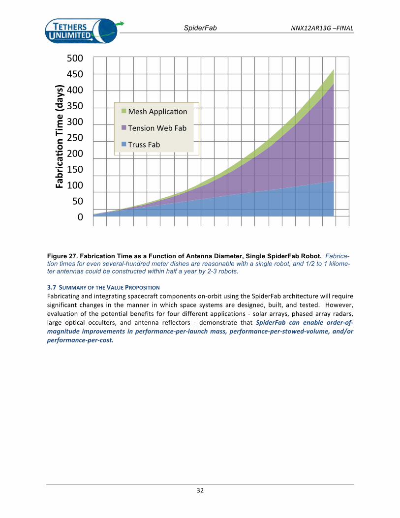
SpiderFab NNX12AR13G –FINAL
32
100" 200" 300" 400" 500" 600" 700" 800" 900" 1000"Dish*Diameter*(m)*
0"50"
100"150"200"250"300"350"400"450"500"
Fabrica'
on*Tim
e*(days)*
Mesh"Applica6on"
Tension"Web"Fab"
Truss"Fab"
Figure 27. Fabrication Time as a Function of Antenna Diameter, Single SpiderFab Robot. Fabrica-tion times for even several-hundred meter dishes are reasonable with a single robot, and 1/2 to 1 kilome-ter antennas could be constructed within half a year by 2-3 robots.
3.7 SUMMARY OF THE VALUE PROPOSITION Fabricating and integrating spacecraft components on-‐orbit using the SpiderFab architecture will require significant changes in the manner in which space systems are designed, built, and tested. However, evaluation of the potential benefits for four different applications -‐ solar arrays, phased array radars, large optical occulters, and antenna reflectors -‐ demonstrate that SpiderFab can enable order-‐of-‐magnitude improvements in performance-‐per-‐launch mass, performance-‐per-‐stowed-‐volume, and/or performance-‐per-‐cost.
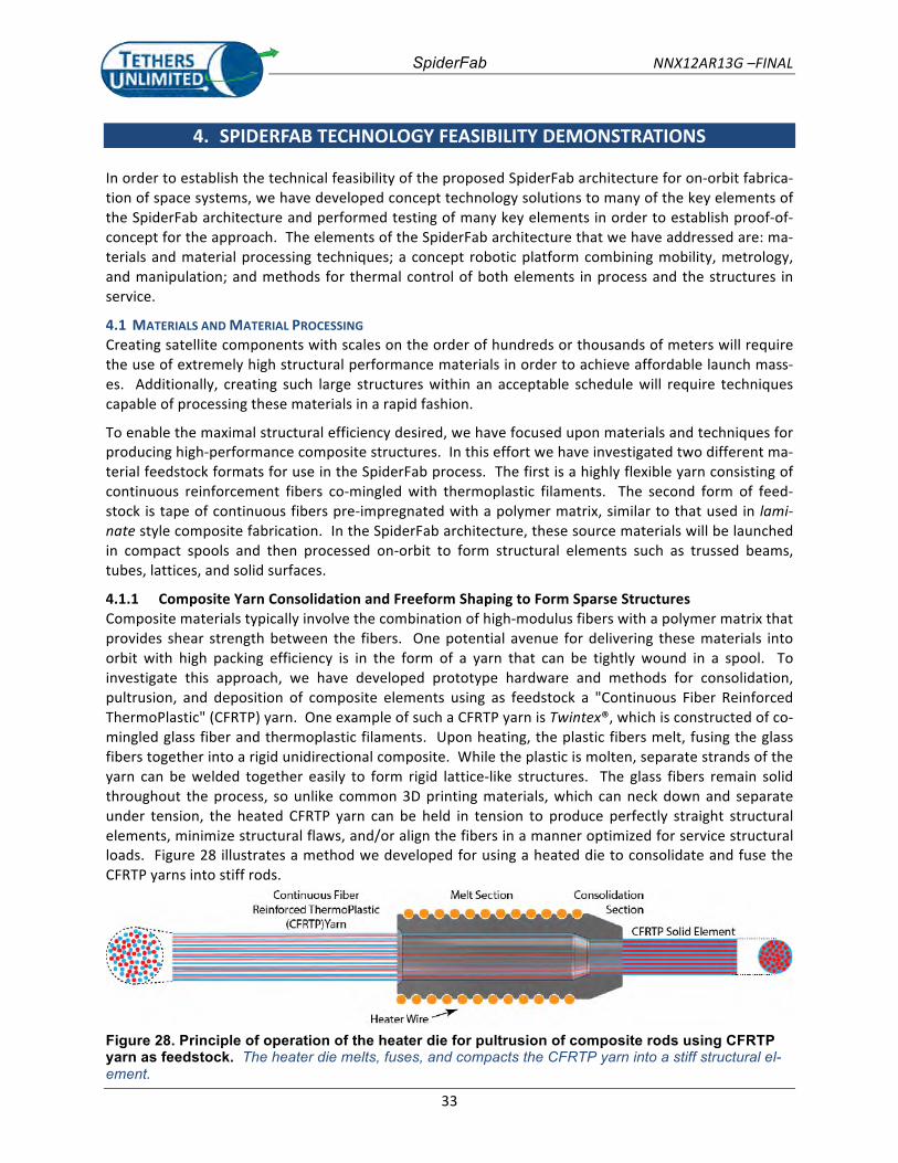
SpiderFab NNX12AR13G –FINAL
33
4. SPIDERFAB TECHNOLOGY FEASIBILITY DEMONSTRATIONS In order to establish the technical feasibility of the proposed SpiderFab architecture for on-‐orbit fabrica-‐tion of space systems, we have developed concept technology solutions to many of the key elements of the SpiderFab architecture and performed testing of many key elements in order to establish proof-‐of-‐concept for the approach. The elements of the SpiderFab architecture that we have addressed are: ma-‐terials and material processing techniques; a concept robotic platform combining mobility, metrology, and manipulation; and methods for thermal control of both elements in process and the structures in service.
4.1 MATERIALS AND MATERIAL PROCESSING Creating satellite components with scales on the order of hundreds or thousands of meters will require the use of extremely high structural performance materials in order to achieve affordable launch mass-‐es. Additionally, creating such large structures within an acceptable schedule will require techniques capable of processing these materials in a rapid fashion.
To enable the maximal structural efficiency desired, we have focused upon materials and techniques for producing high-‐performance composite structures. In this effort we have investigated two different ma-‐terial feedstock formats for use in the SpiderFab process. The first is a highly flexible yarn consisting of continuous reinforcement fibers co-‐mingled with thermoplastic filaments. The second form of feed-‐stock is tape of continuous fibers pre-‐impregnated with a polymer matrix, similar to that used in lami-‐nate style composite fabrication. In the SpiderFab architecture, these source materials will be launched in compact spools and then processed on-‐orbit to form structural elements such as trussed beams, tubes, lattices, and solid surfaces.
4.1.1 Composite Yarn Consolidation and Freeform Shaping to Form Sparse Structures Composite materials typically involve the combination of high-‐modulus fibers with a polymer matrix that provides shear strength between the fibers. One potential avenue for delivering these materials into orbit with high packing efficiency is in the form of a yarn that can be tightly wound in a spool. To investigate this approach, we have developed prototype hardware and methods for consolidation, pultrusion, and deposition of composite elements using as feedstock a "Continuous Fiber Reinforced ThermoPlastic" (CFRTP) yarn. One example of such a CFRTP yarn is Twintex®, which is constructed of co-‐mingled glass fiber and thermoplastic filaments. Upon heating, the plastic fibers melt, fusing the glass fibers together into a rigid unidirectional composite. While the plastic is molten, separate strands of the yarn can be welded together easily to form rigid lattice-‐like structures. The glass fibers remain solid throughout the process, so unlike common 3D printing materials, which can neck down and separate under tension, the heated CFRTP yarn can be held in tension to produce perfectly straight structural elements, minimize structural flaws, and/or align the fibers in a manner optimized for service structural loads. Figure 28 illustrates a method we developed for using a heated die to consolidate and fuse the CFRTP yarns into stiff rods.
Figure 28. Principle of operation of the heater die for pultrusion of composite rods using CFRTP yarn as feedstock. The heater die melts, fuses, and compacts the CFRTP yarn into a stiff structural el-ement.
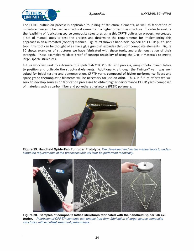
SpiderFab NNX12AR13G –FINAL
34
The CFRTP pultrusion process is applicable to joining of structural elements, as well as fabrication of miniature trusses to be used as structural elements in a higher order truss structure. In order to evalute the feasibility of fabricating sparse composite structures using this CFRTP pultrusion process, we created a set of manual tools to test the process and determine the requirements for implementing this approach in an automated (robotic) manner. Figure 29 shows a hand-‐held 'SpiderFab' CFRTP pultrusion tool; this tool can be thought of as like a glue gun that extrudes thin, stiff composite elements. Figure 30 shows examples of structures we have fabricated with these tools, and a demonstration of their strength. These examples validate proof-‐of-‐concept feasibility of using the CFRTP materials to create large, sparse structures.
Future work will seek to automate this SpiderFab CFRTP pultrusion process, using robotic manipulators to position and pultrude the structural elements. Additionally, although the Twintex® yarn was well suited for initial testing and demonstration, CFRTP yarns composed of higher-‐performance fibers and space-‐grade thermoplastic filaments will be necessary for use on-‐orbit. Thus, in future efforts we will seek to develop sources or fabrication processes to obtain higher-‐performance CFRTP yarns composed of materials such as carbon fiber and polyetheretherketone (PEEK) polymers.
Figure 29. Handheld SpiderFab Pultruder Prototype. We developed and tested manual tools to under-stand the requirements of the processes that will later be performed robotically.
Figure 30. Samples of composite lattice structures fabricated with the handheld SpiderFab ex-truder. Pultrusion of CFRTP elements can enable free-form fabrication of large, sparse composite structures with excellent structural performance.
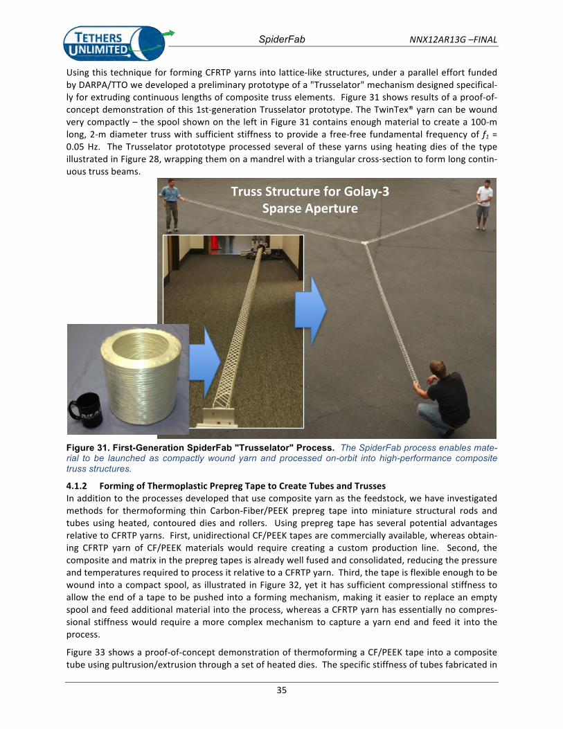
SpiderFab NNX12AR13G –FINAL
35
Using this technique for forming CFRTP yarns into lattice-‐like structures, under a parallel effort funded by DARPA/TTO we developed a preliminary prototype of a "Trusselator" mechanism designed specifical-‐ly for extruding continuous lengths of composite truss elements. Figure 31 shows results of a proof-‐of-‐concept demonstration of this 1st-‐generation Trusselator prototype. The TwinTex® yarn can be wound very compactly – the spool shown on the left in Figure 31 contains enough material to create a 100-‐m long, 2-‐m diameter truss with sufficient stiffness to provide a free-‐free fundamental frequency of f1 = 0.05 Hz. The Trusselator protototype processed several of these yarns using heating dies of the type illustrated in Figure 28, wrapping them on a mandrel with a triangular cross-‐section to form long contin-‐uous truss beams.
Truss%Structure%for%Golay03%Sparse%Aperture%
Figure 31. First-Generation SpiderFab "Trusselator" Process. The SpiderFab process enables mate-rial to be launched as compactly wound yarn and processed on-orbit into high-performance composite truss structures.
4.1.2 Forming of Thermoplastic Prepreg Tape to Create Tubes and Trusses In addition to the processes developed that use composite yarn as the feedstock, we have investigated methods for thermoforming thin Carbon-‐Fiber/PEEK prepreg tape into miniature structural rods and tubes using heated, contoured dies and rollers. Using prepreg tape has several potential advantages relative to CFRTP yarns. First, unidirectional CF/PEEK tapes are commercially available, whereas obtain-‐ing CFRTP yarn of CF/PEEK materials would require creating a custom production line. Second, the composite and matrix in the prepreg tapes is already well fused and consolidated, reducing the pressure and temperatures required to process it relative to a CFRTP yarn. Third, the tape is flexible enough to be wound into a compact spool, as illustrated in Figure 32, yet it has sufficient compressional stiffness to allow the end of a tape to be pushed into a forming mechanism, making it easier to replace an empty spool and feed additional material into the process, whereas a CFRTP yarn has essentially no compres-‐sional stiffness would require a more complex mechanism to capture a yarn end and feed it into the process.
Figure 33 shows a proof-‐of-‐concept demonstration of thermoforming a CF/PEEK tape into a composite tube using pultrusion/extrusion through a set of heated dies. The specific stiffness of tubes fabricated in
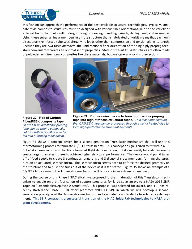
SpiderFab NNX12AR13G –FINAL
36
this fashion can approach the performance of the best available structural technologies. Typically, lami-‐nate-‐style composite structures must be designed with various fiber orientations, due to the variety of external loads that parts will undergo during processing, handling, launch, deployment, and in service. Using these tubes as linear members in a truss structure that is fabricated on-‐orbit means that each uni-‐directionally reinforced tube sees virtually no loads other than compression and tension along its length. Because they are two-‐force-‐members, the unidirectional fiber orientation of the single-‐ply prepreg feed-‐stock conveniently creates an optimal set of properties. State-‐of-‐the-‐art truss structures are often made of pultruded unidirectional composites like these materials, but are generally solid cross-‐sections.
Figure 32. Roll of Carbon-Fiber/PEEK composite tape. CF/PEEK unidirectional prepreg tape can be wound compactly, yet has sufficient stiffness to be fed into a forming mechanism.
Figure 33. Pultrusion/extrusion to transform flexible prepreg tape into high-stiffness structural tubes. This test demonstrated that CF/PEEK tape can be processed through a set of heated dies to form high-performance structural elements.
Figure 34 shows a concept design for a second-‐generation Trusselator mechanism that will use this thermoforming process to fabricate CF/PEEK truss beams. This concept design is sized to fit within a 3U CubeSat volume in order to facilitate low-‐cost flight demonstration, but it can readily be scaled in size to create larger diameter trusses to achieve higher structural performance. The device would pull 6 tapes off of feed spools to create 3 continuous longerons and 3 diagonal cross-‐members, forming the struc-‐ture on an actuated jig mechanism. The jig mechanism serves both to enforce the desired geometry on the structure and to push the truss out of the device as it is fabricated. Figure 35 shows an example of a CF/PEEK truss element the Trusselator mechanism will fabricate in an automated manner.
During the course of this Phase I NIAC effort, we proposed further maturation of this Trusselator mech-‐anism to enable on-‐orbit fabrication of support structures for large solar arrays to a NASA 2012 SBIR Topic on "Expandable/Deployable Structures". This proposal was selected for award, and TUI has re-‐cently started the Phase I SBIR effort (contract NNX13CL35P), in which we will develop a second-‐generation prototype of the Trusselator mechanism and evaluate its applicability to solar array deploy-‐ment. This SBIR contract is a successful transition of the NIAC SpiderFab technologies to NASA pro-‐gram development.
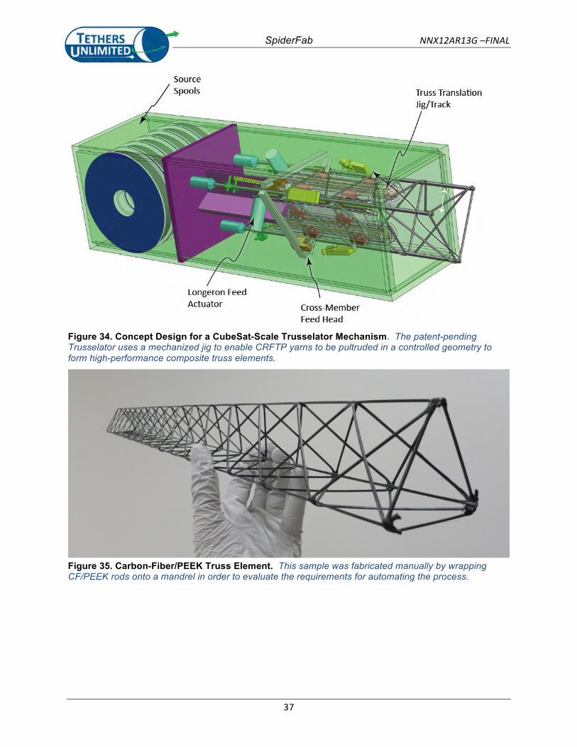
SpiderFab NNX12AR13G –FINAL
37
Figure 34. Concept Design for a CubeSat-Scale Trusselator Mechanism. The patent-pending Trusselator uses a mechanized jig to enable CRFTP yarns to be pultruded in a controlled geometry to form high-performance composite truss elements.
Figure 35. Carbon-Fiber/PEEK Truss Element. This sample was fabricated manually by wrapping CF/PEEK rods onto a mandrel in order to evaluate the requirements for automating the process.
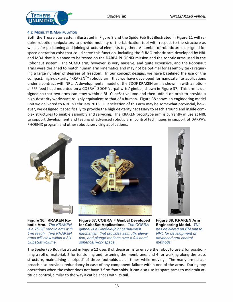
SpiderFab NNX12AR13G –FINAL
38
4.2 MOBILITY & MANIPULATION Both the Trusselator system illustrated in Figure 8 and the SpiderFab Bot illustrated in Figure 11 will re-‐quire robotic manipulators to provide mobility of the fabrication tool with respect to the structure as well as for positioning and joining structural elements together. A number of robotic arms designed for space operation exist that could serve this function, including the SUMO robotic arm developed by NRL and MDA that is planned to be tested on the DARPA PHOENIX mission and the robotic arms used in the Robonaut system. The SUMO arm, however, is very massive, and quite expensive, and the Robonaut arms were designed to match human arm kinematics and may not be optimal for assembly tasks requir-‐ing a large number of degrees of freedom. In our concept designs, we have baselined the use of the compact, high-‐dexterity "KRAKEN™" robotic arm that we have developed for nanosatellite applications under a contract with NRL. A developmental model of the 7DOF KRAKEN arm is shown in with a notion-‐al FFF feed head mounted on a COBRA™ 3DOF 'carpal-‐wrist' gimbal, shown in Figure 37. This arm is de-‐signed so that two arms can stow within a 3U CubeSat volume and then unfold on-‐orbit to provide a high-‐dexterity workspace roughly equivalent to that of a human. Figure 38 shows an engineering model unit we delivered to NRL in February 2013. Our selection of this arm may be somewhat provincial, how-‐ever, we designed it specifically to provide the high dexterity necessary to reach around and inside com-‐plex structures to enable assembly and servicing. The KRAKEN prototype arm is currently in use at NRL to support development and testing of advanced robotic arm control techniques in support of DARPA's PHOENIX program and other robotic servicing applications.
Figure 36. KRAKEN Ro-botic Arm. The KRAKEN is a 7DOF robotic arm with 1-m reach. Two KRAKEN arms will stow within a 3U CubeSat volume.
Figure 37. COBRA™ Gimbal Developed for CubeSat Applications. The COBRA gimbal is a Canfield-joint carpal-wrist mechanism that provides azimuth, eleva-tion, and plunge motions over a full hemi-spherical work space.
Figure 38. KRAKEN Arm Engineering Model. TUI has delivered an EM unit to NRL for development of advanced arm control methods
The SpiderFab Bot illustrated in Figure 12 uses 8 of these arms to enable the robot to use 2 for position-‐ning a roll of material, 2 for tensioning and fastening the membrane, and 4 for walking along the truss structure, maintaining a ‘tripod’ of three footholds at all times while moving. The many-‐armed ap-‐proach also provides redundancy in case of any component failure within one of the arms. During any operations when the robot does not have 3 firm footholds, it can also use its spare arms to maintain at-‐titude control, similar to the way a cat balances with its tail.
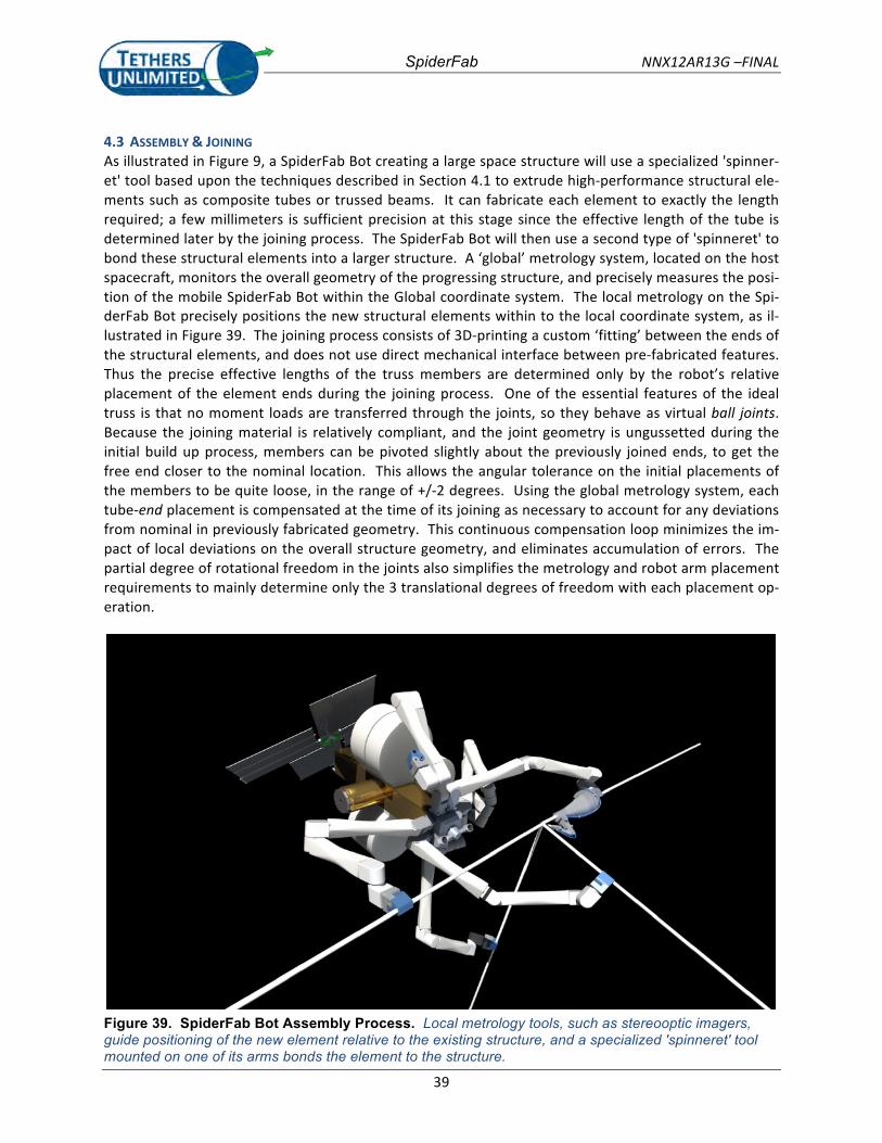
SpiderFab NNX12AR13G –FINAL
39
4.3 ASSEMBLY & JOINING As illustrated in Figure 9, a SpiderFab Bot creating a large space structure will use a specialized 'spinner-‐et' tool based upon the techniques described in Section 4.1 to extrude high-‐performance structural ele-‐ments such as composite tubes or trussed beams. It can fabricate each element to exactly the length required; a few millimeters is sufficient precision at this stage since the effective length of the tube is determined later by the joining process. The SpiderFab Bot will then use a second type of 'spinneret' to bond these structural elements into a larger structure. A ‘global’ metrology system, located on the host spacecraft, monitors the overall geometry of the progressing structure, and precisely measures the posi-‐tion of the mobile SpiderFab Bot within the Global coordinate system. The local metrology on the Spi-‐derFab Bot precisely positions the new structural elements within to the local coordinate system, as il-‐lustrated in Figure 39. The joining process consists of 3D-‐printing a custom ‘fitting’ between the ends of the structural elements, and does not use direct mechanical interface between pre-‐fabricated features. Thus the precise effective lengths of the truss members are determined only by the robot’s relative placement of the element ends during the joining process. One of the essential features of the ideal truss is that no moment loads are transferred through the joints, so they behave as virtual ball joints. Because the joining material is relatively compliant, and the joint geometry is ungussetted during the initial build up process, members can be pivoted slightly about the previously joined ends, to get the free end closer to the nominal location. This allows the angular tolerance on the initial placements of the members to be quite loose, in the range of +/-‐2 degrees. Using the global metrology system, each tube-‐end placement is compensated at the time of its joining as necessary to account for any deviations from nominal in previously fabricated geometry. This continuous compensation loop minimizes the im-‐pact of local deviations on the overall structure geometry, and eliminates accumulation of errors. The partial degree of rotational freedom in the joints also simplifies the metrology and robot arm placement requirements to mainly determine only the 3 translational degrees of freedom with each placement op-‐eration.
Figure 39. SpiderFab Bot Assembly Process. Local metrology tools, such as stereooptic imagers, guide positioning of the new element relative to the existing structure, and a specialized 'spinneret' tool mounted on one of its arms bonds the element to the structure.
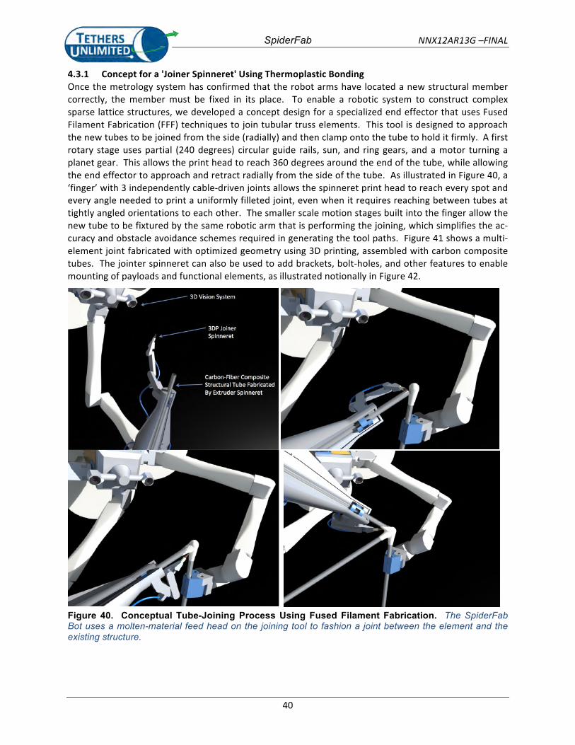
SpiderFab NNX12AR13G –FINAL
40
4.3.1 Concept for a 'Joiner Spinneret' Using Thermoplastic Bonding Once the metrology system has confirmed that the robot arms have located a new structural member correctly, the member must be fixed in its place. To enable a robotic system to construct complex sparse lattice structures, we developed a concept design for a specialized end effector that uses Fused Filament Fabrication (FFF) techniques to join tubular truss elements. This tool is designed to approach the new tubes to be joined from the side (radially) and then clamp onto the tube to hold it firmly. A first rotary stage uses partial (240 degrees) circular guide rails, sun, and ring gears, and a motor turning a planet gear. This allows the print head to reach 360 degrees around the end of the tube, while allowing the end effector to approach and retract radially from the side of the tube. As illustrated in Figure 40, a ‘finger’ with 3 independently cable-‐driven joints allows the spinneret print head to reach every spot and every angle needed to print a uniformly filleted joint, even when it requires reaching between tubes at tightly angled orientations to each other. The smaller scale motion stages built into the finger allow the new tube to be fixtured by the same robotic arm that is performing the joining, which simplifies the ac-‐curacy and obstacle avoidance schemes required in generating the tool paths. Figure 41 shows a multi-‐element joint fabricated with optimized geometry using 3D printing, assembled with carbon composite tubes. The jointer spinneret can also be used to add brackets, bolt-‐holes, and other features to enable mounting of payloads and functional elements, as illustrated notionally in Figure 42.
Figure 40. Conceptual Tube-Joining Process Using Fused Filament Fabrication. The SpiderFab Bot uses a molten-material feed head on the joining tool to fashion a joint between the element and the existing structure.
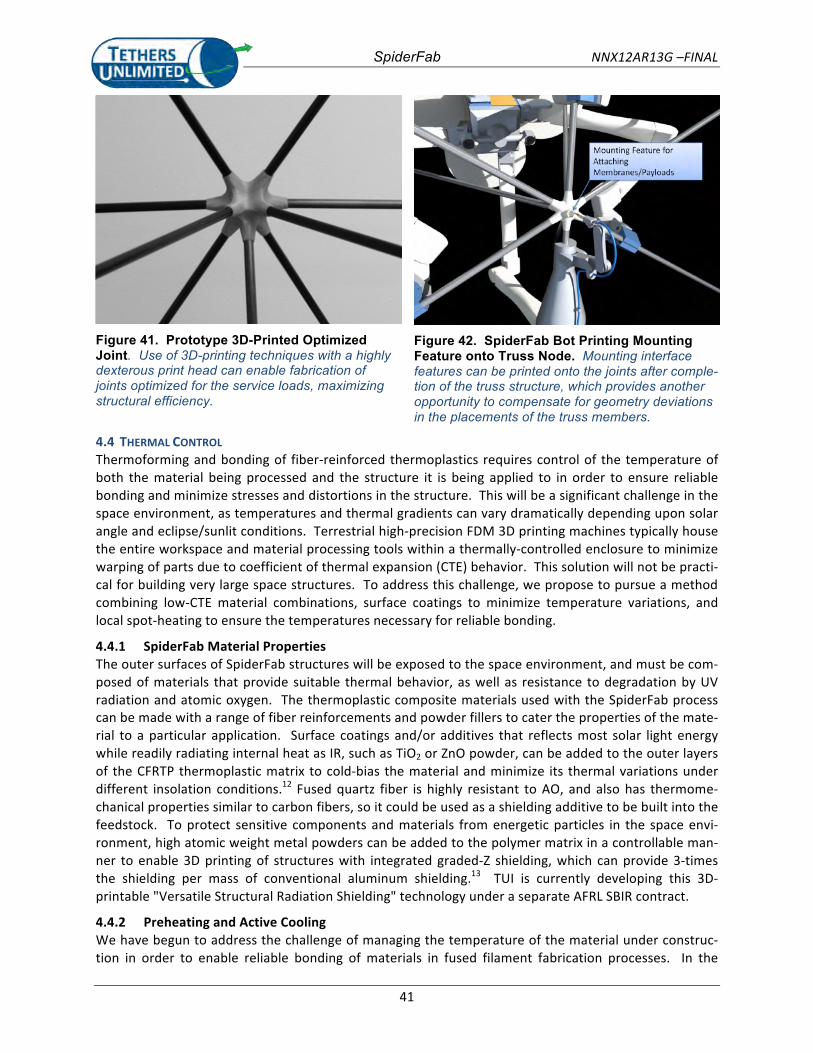
SpiderFab NNX12AR13G –FINAL
41
Figure 41. Prototype 3D-Printed Optimized Joint. Use of 3D-printing techniques with a highly dexterous print head can enable fabrication of joints optimized for the service loads, maximizing structural efficiency.
Figure 42. SpiderFab Bot Printing Mounting Feature onto Truss Node. Mounting interface features can be printed onto the joints after comple-tion of the truss structure, which provides another opportunity to compensate for geometry deviations in the placements of the truss members.
4.4 THERMAL CONTROL Thermoforming and bonding of fiber-‐reinforced thermoplastics requires control of the temperature of both the material being processed and the structure it is being applied to in order to ensure reliable bonding and minimize stresses and distortions in the structure. This will be a significant challenge in the space environment, as temperatures and thermal gradients can vary dramatically depending upon solar angle and eclipse/sunlit conditions. Terrestrial high-‐precision FDM 3D printing machines typically house the entire workspace and material processing tools within a thermally-‐controlled enclosure to minimize warping of parts due to coefficient of thermal expansion (CTE) behavior. This solution will not be practi-‐cal for building very large space structures. To address this challenge, we propose to pursue a method combining low-‐CTE material combinations, surface coatings to minimize temperature variations, and local spot-‐heating to ensure the temperatures necessary for reliable bonding.
4.4.1 SpiderFab Material Properties The outer surfaces of SpiderFab structures will be exposed to the space environment, and must be com-‐posed of materials that provide suitable thermal behavior, as well as resistance to degradation by UV radiation and atomic oxygen. The thermoplastic composite materials used with the SpiderFab process can be made with a range of fiber reinforcements and powder fillers to cater the properties of the mate-‐rial to a particular application. Surface coatings and/or additives that reflects most solar light energy while readily radiating internal heat as IR, such as TiO2 or ZnO powder, can be added to the outer layers of the CFRTP thermoplastic matrix to cold-‐bias the material and minimize its thermal variations under different insolation conditions.12 Fused quartz fiber is highly resistant to AO, and also has thermome-‐chanical properties similar to carbon fibers, so it could be used as a shielding additive to be built into the feedstock. To protect sensitive components and materials from energetic particles in the space envi-‐ronment, high atomic weight metal powders can be added to the polymer matrix in a controllable man-‐ner to enable 3D printing of structures with integrated graded-‐Z shielding, which can provide 3-‐times the shielding per mass of conventional aluminum shielding.13 TUI is currently developing this 3D-‐printable "Versatile Structural Radiation Shielding" technology under a separate AFRL SBIR contract.
4.4.2 Preheating and Active Cooling We have begun to address the challenge of managing the temperature of the material under construc-‐tion in order to enable reliable bonding of materials in fused filament fabrication processes. In the
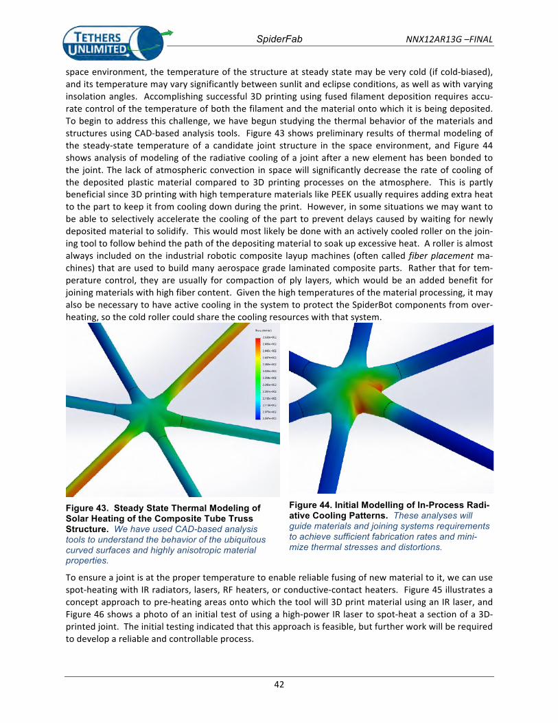
SpiderFab NNX12AR13G –FINAL
42
space environment, the temperature of the structure at steady state may be very cold (if cold-‐biased), and its temperature may vary significantly between sunlit and eclipse conditions, as well as with varying insolation angles. Accomplishing successful 3D printing using fused filament deposition requires accu-‐rate control of the temperature of both the filament and the material onto which it is being deposited. To begin to address this challenge, we have begun studying the thermal behavior of the materials and structures using CAD-‐based analysis tools. Figure 43 shows preliminary results of thermal modeling of the steady-‐state temperature of a candidate joint structure in the space environment, and Figure 44 shows analysis of modeling of the radiative cooling of a joint after a new element has been bonded to the joint. The lack of atmospheric convection in space will significantly decrease the rate of cooling of the deposited plastic material compared to 3D printing processes on the atmosphere. This is partly beneficial since 3D printing with high temperature materials like PEEK usually requires adding extra heat to the part to keep it from cooling down during the print. However, in some situations we may want to be able to selectively accelerate the cooling of the part to prevent delays caused by waiting for newly deposited material to solidify. This would most likely be done with an actively cooled roller on the join-‐ing tool to follow behind the path of the depositing material to soak up excessive heat. A roller is almost always included on the industrial robotic composite layup machines (often called fiber placement ma-‐chines) that are used to build many aerospace grade laminated composite parts. Rather that for tem-‐perature control, they are usually for compaction of ply layers, which would be an added benefit for joining materials with high fiber content. Given the high temperatures of the material processing, it may also be necessary to have active cooling in the system to protect the SpiderBot components from over-‐heating, so the cold roller could share the cooling resources with that system.
Figure 43. Steady State Thermal Modeling of Solar Heating of the Composite Tube Truss Structure. We have used CAD-based analysis tools to understand the behavior of the ubiquitous curved surfaces and highly anisotropic material properties.
Figure 44. Initial Modelling of In-Process Radi-ative Cooling Patterns. These analyses will guide materials and joining systems requirements to achieve sufficient fabrication rates and mini-mize thermal stresses and distortions.
To ensure a joint is at the proper temperature to enable reliable fusing of new material to it, we can use spot-‐heating with IR radiators, lasers, RF heaters, or conductive-‐contact heaters. Figure 45 illustrates a concept approach to pre-‐heating areas onto which the tool will 3D print material using an IR laser, and Figure 46 shows a photo of an initial test of using a high-‐power IR laser to spot-‐heat a section of a 3D-‐printed joint. The initial testing indicated that this approach is feasible, but further work will be required to develop a reliable and controllable process.
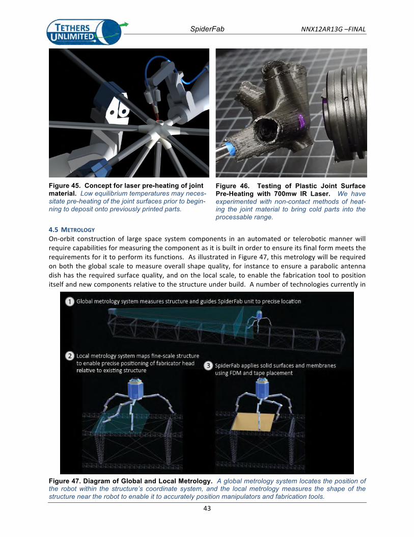
SpiderFab NNX12AR13G –FINAL
43
Figure 45. Concept for laser pre-heating of joint material. Low equilibrium temperatures may neces-sitate pre-heating of the joint surfaces prior to begin-ning to deposit onto previously printed parts.
Figure 46. Testing of Plastic Joint Surface Pre-Heating with 700mw IR Laser. We have experimented with non-contact methods of heat-ing the joint material to bring cold parts into the processable range.
4.5 METROLOGY On-‐orbit construction of large space system components in an automated or telerobotic manner will require capabilities for measuring the component as it is built in order to ensure its final form meets the requirements for it to perform its functions. As illustrated in Figure 47, this metrology will be required on both the global scale to measure overall shape quality, for instance to ensure a parabolic antenna dish has the required surface quality, and on the local scale, to enable the fabrication tool to position itself and new components relative to the structure under build. A number of technologies currently in
Figure 47. Diagram of Global and Local Metrology. A global metrology system locates the position of the robot within the structure’s coordinate system, and the local metrology measures the shape of the structure near the robot to enable it to accurately position manipulators and fabrication tools.
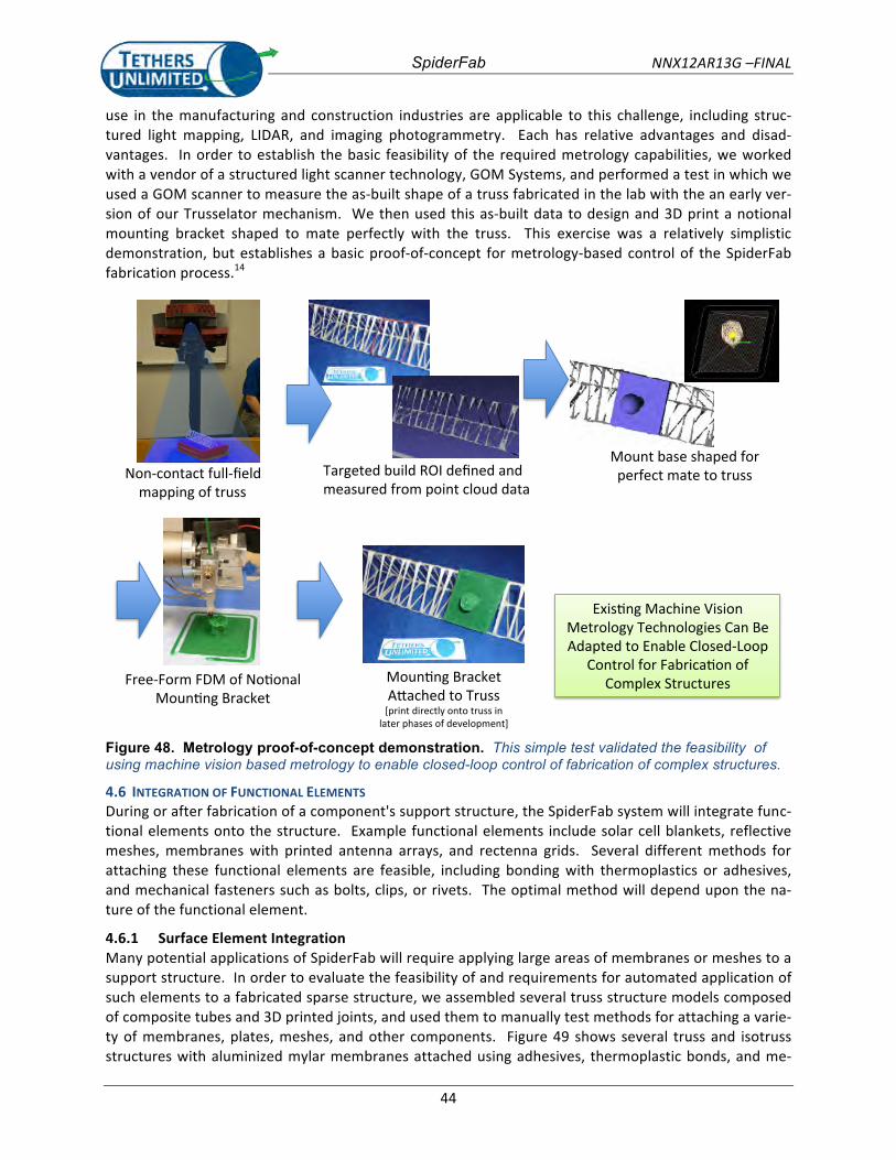
SpiderFab NNX12AR13G –FINAL
44
use in the manufacturing and construction industries are applicable to this challenge, including struc-‐tured light mapping, LIDAR, and imaging photogrammetry. Each has relative advantages and disad-‐vantages. In order to establish the basic feasibility of the required metrology capabilities, we worked with a vendor of a structured light scanner technology, GOM Systems, and performed a test in which we used a GOM scanner to measure the as-‐built shape of a truss fabricated in the lab with the an early ver-‐sion of our Trusselator mechanism. We then used this as-‐built data to design and 3D print a notional mounting bracket shaped to mate perfectly with the truss. This exercise was a relatively simplistic demonstration, but establishes a basic proof-‐of-‐concept for metrology-‐based control of the SpiderFab fabrication process.14
Moun%ng'Bracket''A0ached'to'Truss'[print'directly'onto'truss'in'
later'phases'of'development]'
Non?contact'full?field'mapping'of'truss'
Mount'base'shaped'for'perfect'mate'to'truss'
Free?Form'FDM'of'No%onal'Moun%ng'Bracket'
Targeted'build'ROI'defined'and'measured'from'point'cloud'data'
Exis%ng'Machine'Vision'Metrology'Technologies'Can'Be'Adapted'to'Enable'Closed?Loop'
Control'for'Fabrica%on'of'Complex'Structures'
Figure 48. Metrology proof-of-concept demonstration. This simple test validated the feasibility of using machine vision based metrology to enable closed-loop control of fabrication of complex structures.
4.6 INTEGRATION OF FUNCTIONAL ELEMENTS During or after fabrication of a component's support structure, the SpiderFab system will integrate func-‐tional elements onto the structure. Example functional elements include solar cell blankets, reflective meshes, membranes with printed antenna arrays, and rectenna grids. Several different methods for attaching these functional elements are feasible, including bonding with thermoplastics or adhesives, and mechanical fasteners such as bolts, clips, or rivets. The optimal method will depend upon the na-‐ture of the functional element.
4.6.1 Surface Element Integration Many potential applications of SpiderFab will require applying large areas of membranes or meshes to a support structure. In order to evaluate the feasibility of and requirements for automated application of such elements to a fabricated sparse structure, we assembled several truss structure models composed of composite tubes and 3D printed joints, and used them to manually test methods for attaching a varie-‐ty of membranes, plates, meshes, and other components. Figure 49 shows several truss and isotruss structures with aluminized mylar membranes attached using adhesives, thermoplastic bonds, and me-‐
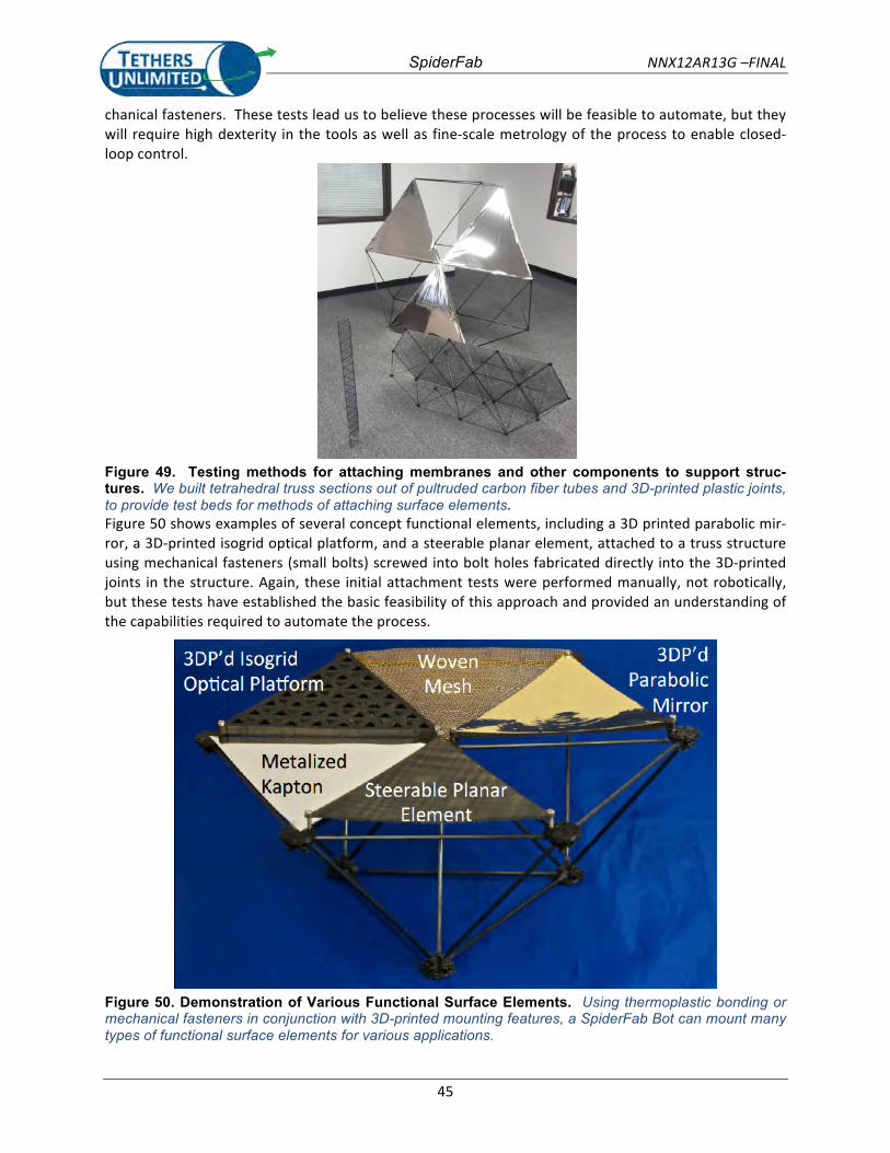
SpiderFab NNX12AR13G –FINAL
45
chanical fasteners. These tests lead us to believe these processes will be feasible to automate, but they will require high dexterity in the tools as well as fine-‐scale metrology of the process to enable closed-‐loop control.
Figure 49. Testing methods for attaching membranes and other components to support struc-tures. We built tetrahedral truss sections out of pultruded carbon fiber tubes and 3D-printed plastic joints, to provide test beds for methods of attaching surface elements. Figure 50 shows examples of several concept functional elements, including a 3D printed parabolic mir-‐ror, a 3D-‐printed isogrid optical platform, and a steerable planar element, attached to a truss structure using mechanical fasteners (small bolts) screwed into bolt holes fabricated directly into the 3D-‐printed joints in the structure. Again, these initial attachment tests were performed manually, not robotically, but these tests have established the basic feasibility of this approach and provided an understanding of the capabilities required to automate the process.
Figure 50. Demonstration of Various Functional Surface Elements. Using thermoplastic bonding or mechanical fasteners in conjunction with 3D-printed mounting features, a SpiderFab Bot can mount many types of functional surface elements for various applications.
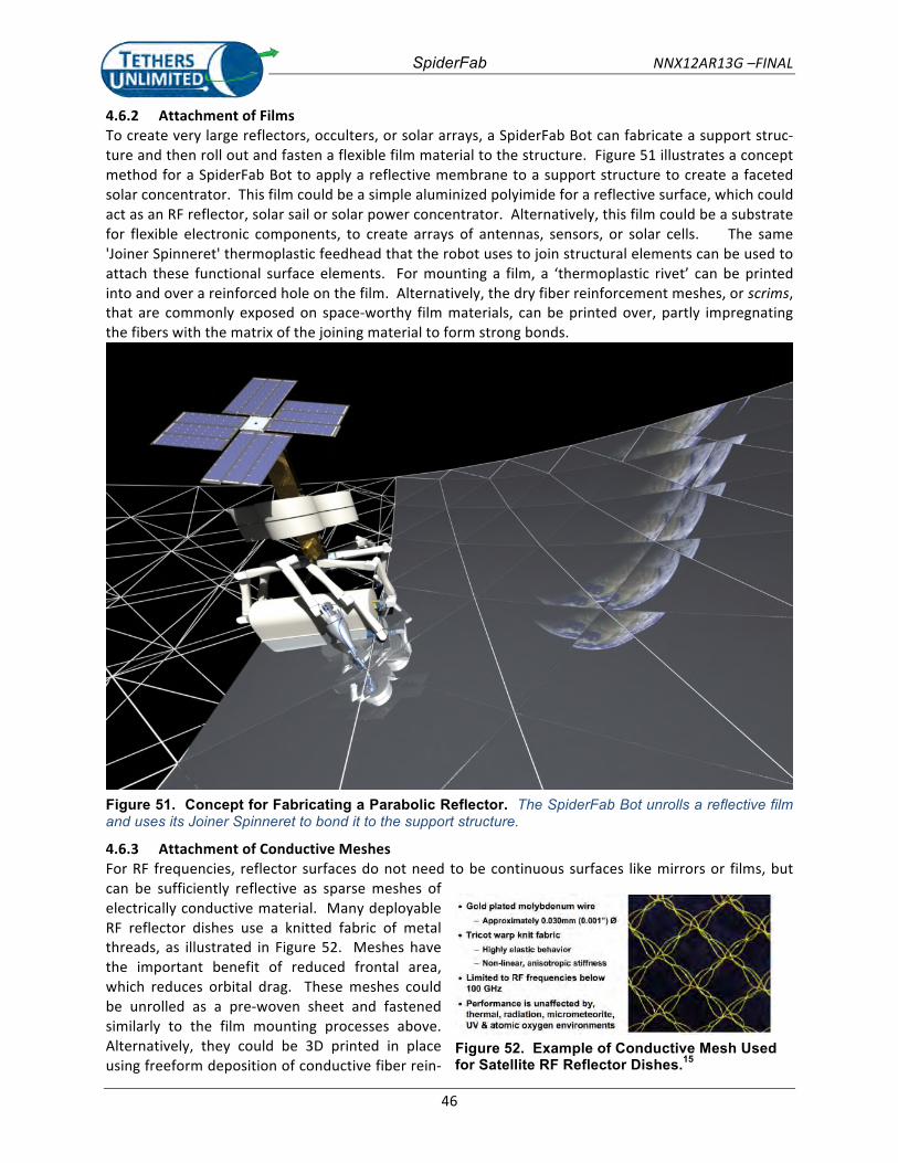
SpiderFab NNX12AR13G –FINAL
46
4.6.2 Attachment of Films To create very large reflectors, occulters, or solar arrays, a SpiderFab Bot can fabricate a support struc-‐ture and then roll out and fasten a flexible film material to the structure. Figure 51 illustrates a concept method for a SpiderFab Bot to apply a reflective membrane to a support structure to create a faceted solar concentrator. This film could be a simple aluminized polyimide for a reflective surface, which could act as an RF reflector, solar sail or solar power concentrator. Alternatively, this film could be a substrate for flexible electronic components, to create arrays of antennas, sensors, or solar cells. The same 'Joiner Spinneret' thermoplastic feedhead that the robot uses to join structural elements can be used to attach these functional surface elements. For mounting a film, a ‘thermoplastic rivet’ can be printed into and over a reinforced hole on the film. Alternatively, the dry fiber reinforcement meshes, or scrims, that are commonly exposed on space-‐worthy film materials, can be printed over, partly impregnating the fibers with the matrix of the joining material to form strong bonds.
Figure 51. Concept for Fabricating a Parabolic Reflector. The SpiderFab Bot unrolls a reflective film and uses its Joiner Spinneret to bond it to the support structure.
4.6.3 Attachment of Conductive Meshes For RF frequencies, reflector surfaces do not need to be continuous surfaces like mirrors or films, but can be sufficiently reflective as sparse meshes of electrically conductive material. Many deployable RF reflector dishes use a knitted fabric of metal threads, as illustrated in Figure 52. Meshes have the important benefit of reduced frontal area, which reduces orbital drag. These meshes could be unrolled as a pre-‐woven sheet and fastened similarly to the film mounting processes above. Alternatively, they could be 3D printed in place using freeform deposition of conductive fiber rein-‐
Figure 52. Example of Conductive Mesh Used for Satellite RF Reflector Dishes.15
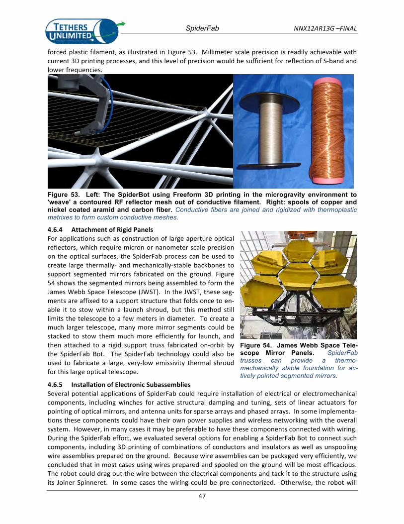
SpiderFab NNX12AR13G –FINAL
47
forced plastic filament, as illustrated in Figure 53. Millimeter scale precision is readily achievable with current 3D printing processes, and this level of precision would be sufficient for reflection of S-‐band and lower frequencies.
Figure 53. Left: The SpiderBot using Freeform 3D printing in the microgravity environment to 'weave' a contoured RF reflector mesh out of conductive filament. Right: spools of copper and nickel coated aramid and carbon fiber. Conductive fibers are joined and rigidized with thermoplastic matrixes to form custom conductive meshes.
4.6.4 Attachment of Rigid Panels For applications such as construction of large aperture optical reflectors, which require micron or nanometer scale precision on the optical surfaces, the SpiderFab process can be used to create large thermally-‐ and mechanically-‐stable backbones to support segmented mirrors fabricated on the ground. Figure 54 shows the segmented mirrors being assembled to form the James Webb Space Telescope (JWST). In the JWST, these seg-‐ments are affixed to a support structure that folds once to en-‐able it to stow within a launch shroud, but this method still limits the telescope to a few meters in diameter. To create a much larger telescope, many more mirror segments could be stacked to stow them much more efficiently for launch, and then attached to a rigid support truss fabricated on-‐orbit by the SpiderFab Bot. The SpiderFab technology could also be used to fabricate a large, very-‐low emissivity thermal shroud for this large optical telescope.
4.6.5 Installation of Electronic Subassemblies Several potential applications of SpiderFab could require installation of electrical or electromechanical components, including winches for active structural damping and tuning, sets of linear actuators for pointing of optical mirrors, and antenna units for sparse arrays and phased arrays. In some implementa-‐tions these components could have their own power supplies and wireless networking with the overall system. However, in many cases it may be preferable to have these components connected with wiring. During the SpiderFab effort, we evaluated several options for enabling a SpiderFab Bot to connect such components, including 3D printing of combinations of conductors and insulators as well as unspooling wire assemblies prepared on the ground. Because wire assemblies can be packaged very efficiently, we concluded that in most cases using wires prepared and spooled on the ground will be most efficacious. The robot could drag out the wire between the electrical components and tack it to the structure using its Joiner Spinneret. In some cases the wiring could be pre-‐connectorized. Otherwise, the robot will
Figure 54. James Webb Space Tele-scope Mirror Panels. SpiderFab trusses can provide a thermo-mechanically stable foundation for ac-tively pointed segmented mirrors.
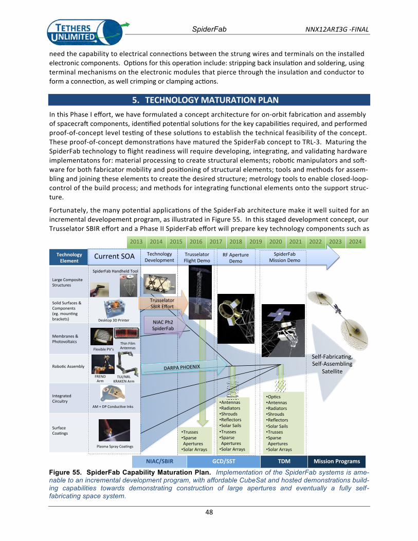
SpiderFab NNX12AR13G' -FINAL
48
need the capability to electrical connections between the strung wires and terminals on the installedelectronic components. Options for this operation include: stripping back insulation and soldering, usingterminal mechanisms on the electronic modules that pierce through the insulation and conductor toform a connection, as well crimping or clamping actions.
5. TECHNOLOGY MATURATION PLANIn this Phase I effort, we have formulated a concept architecture for on-orbit fabrication and assemblyof spacecraft components, identified potential solutions for the key capabilities required, and performedproof-of-concept level testing of these solutions to establish the technical feasibility of the concept.These proof-of-concept demonstrations have matured the SpiderFab concept to TRL-3. Maturing theSpiderFab technology to flight readiness will require developing, integrating, and validating hardwareimplementatons for: material processing to create structural elements; robotic manipulators and soft-ware for both fabricator mobility and positioning of structural elements; tools and methods for assem-bling and joining these elements to create the desired structure; metrology tools to enable closed-loop-control of the build process; and methods for integrating functional elements onto the support struc-ture.
Fortunately, the many potential applications of the SpiderFab architecture make it well suited for anincremental developement program, as illustrated in Figure 55. In this staged development concept, ourTrusselator SBIR effort and a Phase II SpiderFab effort will prepare key technology components such as
2013 2014 2015 2016 2017 2018 2019 2020 2021 2022 2023 2024
TechnologyElement
Large CompositeStructures
Solid Surfaces &Components(eg. mountingbrackets)
Membranes &Photovoltaics
Robotic Assembly
IntegratedCircuitry
SurfaceCoatings
SpiderFab Handheld Tool
Current SOA
Flexible PV’s
FRENDArm
TrussesSparseAperturesSolar Arrays
AntennasRadiatorsShroudsReflectorsSolar SailsTrussesSparseAperturesSolar Arrays
OpticsAntennasRadiatorsShroudsReflectorsSolar SailsTrussesSparseAperturesSolar Arrays
RF ApertureDemo
AM + DP Conductive Inks
Desktop 3D Printer
Self-Fabricating,Self-Assembling
SatelliteTUI/NRL
KRAKEN Arm
Thin FilmAntennas
Plasma Spray Coatings
#"%
TrusselatorFlight Demo
SpiderFabMission Demo
TrusselatorSBIR Effort
NIAC Ph2SpiderFab
DARPA PHOENIX
NIAC/SBIR GCD/SST TDM Mission Programs
TechnologyDevelopment
Figure 55. SpiderFab Capability Maturation Plan. Implementation of the SpiderFab systems is ame-nable to an incremental development program, with affordable CubeSat and hosted demonstrations build-ing capabilities towards demonstrating construction of large apertures and eventually a fully self-fabricating space system.
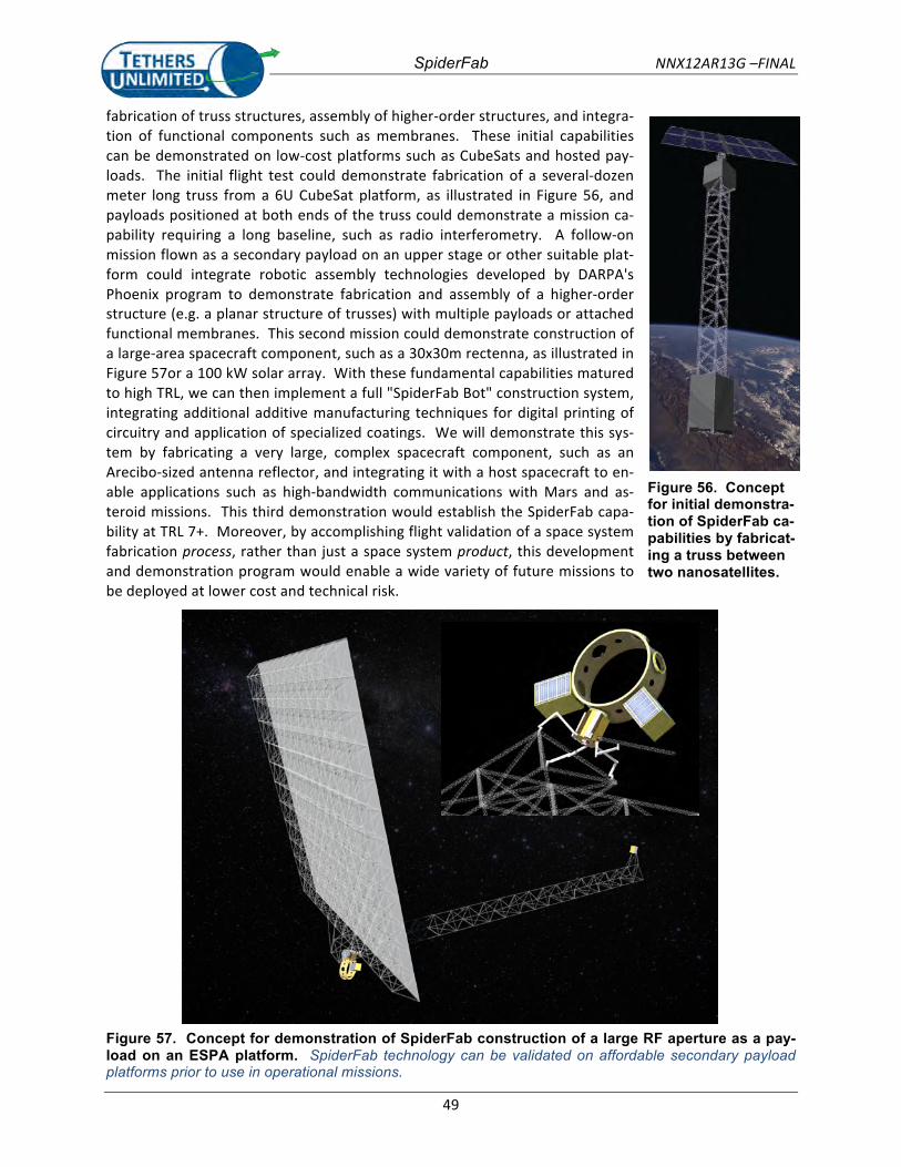
SpiderFab NNX12AR13G –FINAL
49
fabrication of truss structures, assembly of higher-‐order structures, and integra-‐tion of functional components such as membranes. These initial capabilities can be demonstrated on low-‐cost platforms such as CubeSats and hosted pay-‐loads. The initial flight test could demonstrate fabrication of a several-‐dozen meter long truss from a 6U CubeSat platform, as illustrated in Figure 56, and payloads positioned at both ends of the truss could demonstrate a mission ca-‐pability requiring a long baseline, such as radio interferometry. A follow-‐on mission flown as a secondary payload on an upper stage or other suitable plat-‐form could integrate robotic assembly technologies developed by DARPA's Phoenix program to demonstrate fabrication and assembly of a higher-‐order structure (e.g. a planar structure of trusses) with multiple payloads or attached functional membranes. This second mission could demonstrate construction of a large-‐area spacecraft component, such as a 30x30m rectenna, as illustrated in Figure 57or a 100 kW solar array. With these fundamental capabilities matured to high TRL, we can then implement a full "SpiderFab Bot" construction system, integrating additional additive manufacturing techniques for digital printing of circuitry and application of specialized coatings. We will demonstrate this sys-‐tem by fabricating a very large, complex spacecraft component, such as an Arecibo-‐sized antenna reflector, and integrating it with a host spacecraft to en-‐able applications such as high-‐bandwidth communications with Mars and as-‐teroid missions. This third demonstration would establish the SpiderFab capa-‐bility at TRL 7+. Moreover, by accomplishing flight validation of a space system fabrication process, rather than just a space system product, this development and demonstration program would enable a wide variety of future missions to be deployed at lower cost and technical risk.
Figure 56. Concept for initial demonstra-tion of SpiderFab ca-pabilities by fabricat-ing a truss between two nanosatellites.
Figure 57. Concept for demonstration of SpiderFab construction of a large RF aperture as a pay-load on an ESPA platform. SpiderFab technology can be validated on affordable secondary payload platforms prior to use in operational missions.
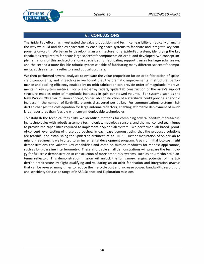
SpiderFab NNX12AR13G –FINAL
50
6. CONCLUSIONS The SpiderFab effort has investigated the value proposition and technical feasibility of radically changing the way we build and deploy spacecraft by enabling space systems to fabricate and integrate key com-‐ponents on-‐orbit. We began by developing an architecture for a SpiderFab system, identifying the key capabilities required to fabricate large spacecraft components on-‐orbit, and developed two concept im-‐plementations of this architecture, one specialized for fabricating support trusses for large solar arrays, and the second a more flexible robotic system capable of fabricating many different spacecraft compo-‐nents, such as antenna reflectors and optical occulters.
We then performed several analyses to evaluate the value proposition for on-‐orbit fabrication of space-‐craft components, and in each case we found that the dramatic improvements in structural perfor-‐mance and packing efficiency enabled by on-‐orbit fabrication can provide order-‐of-‐magnitude improve-‐ments in key system metrics. For phased-‐array radars, SpiderFab construction of the array's support structure enables order-‐of-‐magnitude increases in gain-‐per-‐stowed-‐volume. For systems such as the New Worlds Observer mission concept, SpiderFab construction of a starshade could provide a ten-‐fold increase in the number of Earth-‐like planets discovered per dollar. For communications systems, Spi-‐derFab changes the cost equation for large antenna reflectors, enabling affordable deployment of much larger apertures than feasible with current deployable technologies.
To establish the technical feasibility, we identified methods for combining several additive manufactur-‐ing technologies with robotic assembly technologies, metrology sensors, and thermal control techniques to provide the capabilities required to implement a SpiderFab system. We performed lab-‐based, proof-‐of-‐concept level testing of these approaches, in each case demonstrating that the proposed solutions are feasible, and establishing the SpiderFab architecture at TRL-‐3. Further maturation of SpiderFab to mission-‐readiness is well-‐suited to an incremental development program. A pair of initial low-‐cost flight demonstrations can validate key capabilities and establish mission-‐readiness for modest applications, such as long-‐baseline interferometry. These affordable small demonstrations will prepare the technolo-‐gy for full-‐scale demonstration in construction of more ambitious systems, such as an Arecibo-‐scale an-‐tenna reflector. This demonstration mission will unlock the full game-‐changing potential of the Spi-‐derFab architecture by flight qualifying and validating an on-‐orbit fabrication and integration process that can be re-‐used many times to reduce the life-‐cycle cost and increase power, bandwidth, resolution, and sensitivity for a wide range of NASA Science and Exploration missions.
SpiderFab NNX12AR13G –FINAL
51
REFERENCES 1. Pappa, R., et al., "Solar Array Structures for 300 kW-‐Class Spacecraft", Space Power Workshop, April
24, 2013. 2. Dorsey, J.T. et al., "An Efficient and Versatile Means for Assembling and Manufacturing Systems in
Space," AIAA Paper 2012-‐5115. 3. Rhodes, M.D & Will, R.W., NASA TP-‐3448. 4. Doggett, W., "Robotic Assembly of Truss Structures for Space Systems and Future Research Plans,"
IEEE paper 0-‐8703-‐7231, 2002. 5. Browning, D.L., "On-‐Orbit Fabrication and Assembly of Composite Structures", AIAA-‐78-‐1654, AIAA
Conference on Large Space Platforms, Los Angeles, CA, Sept 1978. 6. Mikulas, M.M., et al., "Truss Performance and Packaging Metrics," NASA Technical Document
20060008916. 7. Murphey, T.W., Hinkle, J.D., "Some Performance Trends in Hierarchical Truss Structures," AIAA-‐2-‐-‐3-‐
1903. 8. Davis, G.L., Tanimoto, R.L, "Mechanical Development of Antenna Systems", Chapter 8 in Spaceborne
Antennas for Planetary Exploration, Deep Space Communications and Navigation Series, Imbriale, W.A. Editor, John Wiley & Sons.
9. Cash, W., et al., "Astrophysics Strategic Mission Concept Study: The New Worlds Observer," 24 April 2009.
10. Cash, W., personal commun., 4Feb2013. 11. Data extracted from DARPA/TTO Phoenix Program Industry Day Briefing, 11Feb13. 12. Browning, L., et al., "Space Construction Automated Fabrication Experiment Definition Study
(SCAFEDS) Final Report," NAS9-‐15310, 12 May 1978. 13. Wrobel, J., et al., "Versatile Structural Radiation Shielding and Thermal Insulation through Additive
Manufacturing," Paper SSC13-‐III-‐3, 2013 USU Small Satellite Conference, August 10 2013. 14. This metrology demonstration was performed under a separate, parallel contract effort, DARPA/TTO
contract HR0011-‐11-‐C-‐0107. 15. Image taken from http://www.kiss.caltech.edu/workshops/apertures2008/talks/thomson.pdf

![Orbit type: Sun Synchronous Orbit ] Orbit height: …...Orbit type: Sun Synchronous Orbit ] PSLV - C37 Orbit height: 505km Orbit inclination: 97.46 degree Orbit period: 94.72 min ISL](https://img.pdfslide.us/doc/110x75/5f781053e671b364921403bc/orbit-type-sun-synchronous-orbit-orbit-height-orbit-type-sun-synchronous.jpg)


![MeasuringtheAbundanceof sub-kilometer sized Kuiper Belt ... · PDF filearXiv:1210.8155v1 [astro-ph.EP] 30 Oct 2012 MeasuringtheAbundanceof sub-kilometer sized Kuiper Belt Objects usingStellar](https://img.pdfslide.us/doc/110x75/5ab3edd37f8b9a1a048b6517/measuringtheabundanceof-sub-kilometer-sized-kuiper-belt-12108155v1-astro-phep.jpg)

![[ArcFM™ Solution] Orbit - Field data collection for ArcFM](https://img.pdfslide.us/doc/110x75/55d5a956bb61eb75358b459b/arcfm-solution-orbit-field-data-collection-for-arcfm.jpg)