Embed Size (px)
Citation preview
· spiderbeam construction guides ·
· 20/15/10m ·
· 20/17/15/12/10m ·
· 20/17/15m ·
· 30/17/12m ·
© df4sa 2002-2005 Version 2.20 dipl.-ing cornelius paul · liebigstrasse 2-20 · d-22113 hamburg · [email protected] · www.spiderbeam.net

1
Contents
1. Introduction page 3 1.1. Spiderbeam Fundamentals page 4 1.2. Materials List page 5 2. Preliminary Tasks page 6 2.1. Constructing the spider center joint page 6 2.1.1 Machining the Metal Parts page 8 2.1.2 Assembly page 8 2.2. Fabricating the Plastic Insulators & Guy Lines page 9 2.2.1 Fabricating the Plastic Insulators page 9 2.2.2 Fabricating the Guy Lines page 9 2.2.3 Cutting the VELCRO® Straps page 10 2.3. Fabricating the Reflector & Director Elements page 11 2.3.1 Cutting the Wire Elements page 11 2.3.2 Attaching Insulators & Guy Lines page 12 2.4. Fabricating the Driven Elements page 13 2.4.1 Cutting the Wire Elements page 13 2.4.2 Fabricating the symmetric feedlines page 14 2.4.3 Attaching Insulators & Guy Lines page 15 2.5. Fabricating the Balun (Coax Choke) page 16 2.5.1 Machining the Balun Enclosure page 16 2.5.2 Inserting the Balun page 17 3. Assembly page 18 3.1. Assembling the supporting cross [ spider ] page 18 3.1.1 Mounting the Vertical Mast page 18 3.1.2 Mounting the Fiberglass Poles page 18 3.2. Mounting the Reflector & Director Elements page 21 3.3. Mounting the Driven Elements page 22 3.4. SWR Alignment page 24 4. „Heavy Duty” Version for fixed Installation page 25 4.1. Materials List page 25 4.2. Changes during assembly of antenna page 26 5. Additional Versions for other frequency bands page 28 5.1. Element Lengths for single mode use (20/15/10m - CW/SSB only) page 28 5.2. 5-Band Version (20-17-15-12-10m) page 29 5.2.1 Materials List page 29 5.2.2 Fabricating the Wire Elements (Reflectors/Directors/Drivers) page 30 5.2.3 Assembly Drawings for the 5-Band Version page 31

2
5.3. „low sunspot“ version (20-17-15m) page 32 5.3.1 Materials List page 32 5.3.2 Fabricating the Wire Elements (Reflectors/Directors/Drivers) page 32 5.3.3 Assembly Drawings page 33 5.4. WARC Version (30-17-12m) page 34 5.4.1 Materials List page 34 5.4.2 Fabricating & Attaching the Guy lines page 34 5.4.3 Fabricating the Wire Elements (Reflectors/Directors/Drivers) page 35 5.4.4 Assembly Drawings page 36
Conversion factors for dimensions in feet/inches: 1 foot = 30.48cm – 1 inch = 2.54 cm
Example: 959cm = 31.463 ft = 31 ft 5.56 in = 31' 5 ½''

3
1. Introduction By following this step-by-step construction guide you can build your own spiderbeam from scratch! It was written with the intent to make it suitable for newcomers as well. Send me an e-mail or letter if there is still something not clear. Any further suggestions are very welcome. This guide will be updated frequently from your questions and suggestions. You can always get a free PDF copy of the latest version at www.spiderbeam.net !
All the necessary parts can be found on the materials list. (page 5). All parts listed in the materials list are contained in the kit offered in addition to this construction guide.
Chapter 2 describes all the Preliminary Tasks. These chores have to be done only once, before assembling the antenna for the first time. You will notice that the preliminary tasks cover the larger part of the construction guide.
A great part of these preliminary tasks is the machining of the aluminum sheet metal and tubes
(drilling holes and slots etc), and also the plastic parts. All the machining has been done already to
the parts contained in the Material kit. Thus they will be marked with a little note on the side of the text:
Chapter 3 describes the Final Assembly tasks. These chores have to be done each time during assembly or disassembly of the antenna. Final assembly is done quite quickly: mount the center joint, put in the fiberglass tubes, attach the guy lines, use the Velcro straps to attach the wires to the spider, done. With a bit of practice you will be finished in 1 hour. All you need is two #10 spanners.
At the beginning of every chapter you will find a list of all the parts needed in that chapter. Before starting to work on the chapter it is a good idea to put all the necessary parts in one place. Thus, when you finish the chapter you will have an automatic check whether you used up all the parts. Have fun building the antenna! Best of luck and successful working!
Follow this guide to build a copy of this antenna for your personal use. Any kind of commercial use is strictly prohibited. All rights reserved by the author. Reproducing of this construction guide only with written permission of the author.
Putting up antennas, towers and masts can be dangerous. Please be careful and patient, use common sense and proper tools and wear protective gear. Any part of the system can fall down or come into contact with lethal high voltage lines. While the antenna is in operation, make sure that nobody can touch any portion of the antenna. Deadly voltages and currents may exist. The use of this antenna is at your own risk. Please act responsible. Thank you!
Kit contains prefabricated part

4
1.1. Spiderbeam Fundamentals
The spiderbeam is a Tribander Yagi for 20-15-10m. It is constructed of 3 interlaced wire yagi antennas strung on a common fiber glass spider. These are: a 3-element yagi for 20m, a 3-element yagi for 15m and a 4-element yagi for 10m. In contrast to a regular yagi the director and reflector elements are bent in V-shape. The driven elements for 10m and 20m are fed through a short piece (approx. 50cm) of symmetric feed line, the 15m driven element is fed directly. All feedlines are tied together in the feedpoint of the 15m driver and attached to the balun (coax choke or current balun). Feed point impedance is 50Ω. Only a single coax cable is necessary. Forward gain and Front-to-Back ratio of the spiderbeam is equivalent to a regular tribander with 6-7m boom length. Further development yielded an Upgrade to a 5-Band Beam (20-17-15-12-10m): The basic design principle remains the same. A 2-ele Yagi (Driver & Reflector) for 17m and a 2-ele Yagi (Driver & Reflector) for 12m could be added without affecting the patterns on 20/15/10m. The drivers for 17/12m are fed through short pieces of symmetric transmission line as well. These feed lines are also attached to the common feed point, so even for 5 Bands only a single coax cable is needed. Chapter 5 further describes additional versions for 30-17-12m (WARC) and 20-17-15m. This antenna was designed and optimized for portable operation. It is a lightweight construction (weight is 6.5kg) with a low wind load. It can be put up by a single person in a few hours – and needs only a lightweight push-up mast as a supporting structure. With the development of this second edition, a lot of effort was put into optimizing assembly time and handling. By using special fiberglass segments for the spreader poles, plastic rope tensioners and quick fasteners (weatherproof Velcro straps), assembly time could be reduced substantially and handling became a lot easier. Many people wanted to use the Spiderbeam not only for portable activities but also in fixed installations at home, so a specially reinforced “Heavy Duty” Version for permanent installation was developed (see chapter 4). The first one to build a 3ele Yagi with the elements bent in V-shape was G4ZU, who called it the "Bird-Yagi“ or "Bow-and-Arrow Yagi“. I heard of this principle for the first time in 1998 by W9XR. I could not find a multiband design anywhere in literature and decided to design one myself. Many thanks to everybody who helped during the development phase, especially DF4RD, DF9GR, DJ6LE, DL6LAU, HA1AG, HB9ABX, W4RNL, WA4VZQ. Also MNI TNX to everybody who helped translating this document to other languages: 9A6C, BG7IGG, CT1IUA, CT3EE, EA2PA, F2LZ, F4ANJ, F5IJT, F6IIE, G3MRC, G3SHF (& Team), HB9ABX, I0SKK, IZ5DIY, JA1KJW, LX2AJ, OH6NT, OK1DMU, OZ8A, PB0P, PC2T, PE2RID, S51TA, S57XX, SM0ETT, SM0JZT, RA3TT, RV3DA, YC0CRA, YU1QT.

5
1.2. Materials List Nr. quantity description 1 20 fiberglass tube segments, length = 1.15m, diameter 35mm, 1mm wall thickness
2 4 aluminium tubes, outer diameter 40mm, wall thickness 2mm, length = 175mm
3 8 aluminium tubes, outer diameter 10mm, wall thickness 1mm, length = 35mm
4 2 aluminium sheet metal, thickness 1mm, length x depth = 220x220mm
5 2 V2A ‘U’-section, 40x25mm, wall thickness 2mm, length = 110mm
6 1 aluminum ‘U’-section, 15x15mm, wall thickness 1,5mm, length = 200mm
7 8 bolts, V2A, M6x55 (V2A = stainless steel)
8 4 bolts, V2A, M6x30 (M6x30 = 6mm diameter, 30mm shaft length)
9 2 bolts, V2A, M6x16
10 2 U-bolts, V2A, M6, U-diameter 60mm, shaft length 95mm, thread length 45mm
11 22 M6 nuts, V2A
12 30 M6 washers, V2A
13 12 M6 lock-washers, V2A
14 4 screws, V2A, M3x10
15 4 M3 nuts, V2A
16 6 rubber sealing washers for M6
17 47m Kevlar guy line, 1.5mm diameter
18 82m PVDF monofilament fiber line, 1mm diameter
19 66 Plastic - Insulators, black Polyethylene, UV resistant
20 8 Rubber O-Rings (EPDM, UV resistant), 28x6mm
21 5m Double-sided Velcro® Band (Hooks/Loops), Polyester, UV resistant, 20mm wide
22 1.5m Velcro® Band (Loops), Polyester, UV resistant, 50mm wide
23 1 25ml package, 5-Min Epoxid or similar glue
24 73m Wireman CQ-532 stranded Copperweld silky wire, PE-Insulation, 1mm diameter
25 10 M6 tubular cable lugs, tin plated copper, 6 of them with 90° angle
26 1m Heat shrink tube 6/2mm with hotmelt glue inside
27 30cm Heat shrink tube 3/1mm with hotmelt glue inside
28 1 weatherproof plastic enclosure, 120x90x55mm, waterproof
29 1m Teflon Coax cable RG142 (or RG303)
30 1 Ferrite toroid ring FT-240-61
31 1 PL Coax socket SO239
32 1 Rubber gasket for Coax socket
33 1 M3 soldering tag
34 1 20cm diameter spool
35 4 sealing caps for the fiberglass tubes (pos. 1) The quantities specified here are valid for building the 3-Band portable Version. For all other versions (5-Band Version, WARC Version, Heavy Duty Version, etc.) please see the additional materials lists at the beginning of the chapter describing these versions.

6
2. Preliminary Tasks All the chores described in Chapter 2 have to be done only once, before the first assembly of the antenna.
2.1. Constructing the spider center joint parts necessary: Nr. quantity description 2 4 aluminium tubes, outer diameter 40mm, wall thickness 2mm, length = 175mm 3 8 aluminium tubes, outer diameter 10mm, wall thickness 1mm, length = 35mm 4 2 aluminium sheet metal, thickness 1mm, length x depth = 220x220mm 5 2 V2A ‘U’-section, 40x25mm, wall thickness 2mm, length = 110mm 7 8 bolts, V2A, M6x55 (M6x55 = 6mm diameter, 55mm shaft length)
11 8 M6 nuts, V2A (V2A = stainless steel) 12 16 M6 washers, V2A 13 8 M6 lock-washers, V2A
2.1.1. Machining the Metal Parts
Prepare both of the 1mm thick aluminum plates in the following way: Cut a 60mm diameter hole in the center. Drill or punch 8 slots positioned symmetrically according to the drawing. These slots should be 15mm long and 6,5mm wide:
(all dimensions in mm)
center joint
Kit contains prefabricated plates

7
Drill 2 holes (6,5mm diameter) into each of the 4 aluminum tubes. Use a saw or file to make 2 cutouts (half round, 6mm deep, 28mm wide) on one end of each tube. These cutouts will be necessary when mounting the tubes as a cross later on. (See page 8).
Now prepare the two 110mm long stainless steel “U”-sections: Drill two 12mm long slots (7mm wide) into the bottom leg, and two 15mm holes into the top leg, just above the slots (these 15mm holes make it a lot easier to mount the bolts through the slots later on). As pictured below, use a saw or file to cut a series of „teeth“ (2mm high, 3mm wide) into each leg. Drill two 6.5mm holes into the center leg.
As a last step, cut the 10mm diameter aluminum tube into 8 pieces of exactly 35mm length. They will serve as sleeves when assembling the center joint (see next page):
Kit contains prefabricated tubes
Kit contains prefabricated sleeves
6,5mm holes
Kit contains prefabricated U sections
bottom leg
top leg
center leg

8
2.1.2. Assembly
You are now ready to assemble the center joint: Put the four tubes between the two aluminum plates, then put a bolt through each slot and mount it. Use washers on either end of the bolts so they have a better grip. Stick the bolts through the 10mm sleeves inside the 40mm tubes. These sleeves are quite important because without them the tubes will crush when firmly tightening the bolts: When putting the antenna up for a long term, use the supplied lock-washers as well, to prevent the nuts from loosening through vibration. If you have problems mounting the sleeves, cut a provisionary picker arm, e.g. from a piece of cardboard, and use it to manoeuvre the sleeve into the tube. On one side of the 60mm hole, the same bolts also serve to mount the U-sections. Mount one U-section on the upper plate and the other one directly below it on the lower plate. The U-bolts that secure the antenna to the mast are mounted to these U-sections later on (see Chapter 3.1.2). By now you will understand the reason for drilling the long slots instead of just round holes: Sliding the aluminum tubes in and out makes it possible to vary the diameter of the vertical antenna mast from 30-60mm. With the long slots the tubes can always be positioned in a way that the mast is perfectly pinched between them. Hence most of the load that normally stresses the U-bolts is transferred to the tubes. The U-bolts are only necessary to prevent the antenna from rotating on the mast. With this construction it is possible to use a wide range of vertical mast diameters without compromising stability. The wide diameter range means more flexibility when putting up the antenna. Now you will also understand the reason for the cutout made at one end of each tube. Without the cutout the variation range of the antenna mast diameter would be only 40-60mm. Many push-up masts have top sections smaller than 40mm. Most boom-to-mast plates put the antenna on one side of the mast, thereby putting its center of gravity on one side of the mast. With the center joint described here the mast goes right through the center of gravity. Antenna weight and vertical torque momentum are optimally distributed on the mast and rotator, which means the load on these parts is reduced. The equal weight distribution also helps a lot when putting the antenna up on portable push-up masts.
Slide tubes in and out to fit mast diameter
9
2.2. Fabricating the Plastic Insulators & Guy Lines parts necessary: Nr. quantity description 17 47m Kevlar guy line, 1.5mm diameter 18 20m PVDF monofilament fiber line, 1mm diameter 19 66 Plastic - Insulators, black Polyethylene, UV resistant 21 5m Double-sided Velcro® Band (Hooks/Loops), Polyester, UV resistant, 20mm wide 22 1.5m Velcro® Band (Loops), Polyester, UV resistant, 50mm wide 23 1 25ml package, 5-Min Epoxid or similar glue
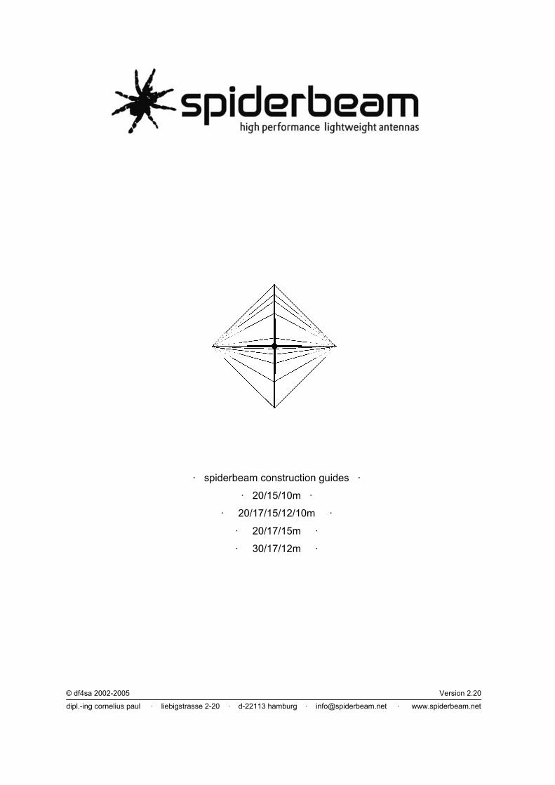
2.2.1. Fabricating the Plastic Insulators
These plastic insulators are very functional and can be used for 3 different purposes when assembling the antenna:
- as an insulator at the end of a wire element, - as a guy tensioner for all guy lines - as center insulator for the driven elements.
It was found that the shape pictured here is very appropriate for all purposes and can be milled from round stock with 12mm diameter (black Polyethylene, UV resistant). 2.2.2. Fabricating the Guy Lines Cut the Kevlar rope into 8 pieces of 580 cm and melt the ends with a lighter, to prevent them from feazing. Attach an „insulator“ to each end of the pieces. It serves as a guy tensioner here. The procedure can be seen from the picture above: put the rope through the long slot and then out again through the 3mm hole. Attach one or more knots to the stub hanging out of the 3mm hole, so the rope does not slip back in.
insulator at wire end
center insulator of driven element
rope tensioner at guy line end
Kit contains prefabricated Insulators

10
After knotting, the distance between the two knots should be 535 cm. Leave the knot(s) a bit loose on one end of the rope, so you can adjust it during the first assembly of the antenna. Cut the PVDF-Monofil line into 4 pieces of 500 cm and attach guy tensioners („Insulators“) at each end. The length between the knots should be 461 cm here. Same thing, you might leave the knot(s) a bit loose on one end, so you can adjust it during the first assembly of the antenna. 2.2.3. Cutting the Velcro® Straps Cut the 20mm wide double-sided Velcro band into 9 pieces of 40cm and 2 pieces of 70cm. The 40cm long straps will be used for attaching the wire elements to the boom. The 70cm straps will be used for attaching the balun box to the vertical mast. Cut the 50mm band into 9 pieces of 11cm and two somewhat longer pieces (depending on the diameter of your vertical mast). Use the epoxy glue to attach the 11cm long pieces to the boom. One piece must be glued to the boom at each element attachment point (see assembly drawing on page 21). Carefully clean the fiberglass tube and sand the spot with a fine sanding paper before applying the glue. It makes sense to mix the 2 components directly on the back of the 50mm Velcro, cover the whole strip and glue it to the pole segment. A thin layer of glue is sufficient. While the glue cures (5 minutes) the Velcro strip can be held in place perfectly by winding a piece of sticky tape around it. 50mm
distance between knots: 8x Kevlar: 535cm – 4xMonofil: 461cm

11
2.3. Fabricating the Reflector & Director Elements parts necessary: Nr. quantity description 18 46m PVDF monofilament fiber line, 1mm diameter 19 28 Plastic - Insulators, black Polyethylene, UV resistant 24 48m Wireman CQ-532 stranded Copperweld silky wire, PE-Insulation, 1mm diameter 34 1 20cm diameter spool
2.3.1. Cutting the Wire Elements A few words regarding the wire material in advance, before cutting the wire: Copperweld® is a trade name for copper clad steel wire. This wire has the HF conducting properties of copper wire combined with the strength of steel wire. The benefit of good conduction properties are low losses of course. The high tensile strength (resulting in low or no stretch) is at least of the same importance when building multi-element wire antennas. With these antennas, the element lengths must be must be kept exactly to the specified lengths (even 1cm does matter!). The first versions of the spider beam were built using normal (soft) enameled copper wire. Each time when assembling and disassembling the antenna, some elements had stretched up to 10cm. As a result, the resonant frequencies of the elements change, leading to a bad deterioration of the radiation pattern, especially the front-to-back ratio. Unfortunately single wire Copperweld is quite difficult to handle. Therefore the “Wireman” sells a specially made stranded Copperweld wire with UV resistant PE insulation jacket. This type of wire combines the 2 benefits mentioned above and is very easy to handle. It is therefore recommended for the construction of this antenna. Velocity Factor When using wire with an insulation jacket the physical length of the wire is approximately 1-10% shorter than its electrical length at high frequency. The insulation introduces some kind of velocity factor which depends of the type and thickness of the insulation. It must be determined very carefully and as precisely as possible. The element lengths derived from (computer) calculations must be corrected by this factor when building the antenna in real life. Therefore I would like to point out once again that the lengths specified in the tables below are only correct when using the wire specified here! When using other kind of wires (especially insulated ones) you must determine its velocity factor and adjust the lengths accordingly! Otherwise the radiation pattern will be affected badly, as mentioned above.
However, let us cut the wire lengths now:
ATTENTION! THE WIRES MUST BE CUT VERY PRECISELY!! Even an error of one centimeter (!!) will make a difference. A yard-stick is not suitable for this task because you can only measure partial lengths and must add them together. This procedure will easily introduce a cumulative error of ± 10cm or worse. The measurements must definitely be done in one piece! A non-stretching plastic tape measure (minimum 11m long) is best suited for the job.
Perform the measuring and cutting on a plain and even surface (minimum 11m long), like on a concrete street or parking lot. Pull the wire straight and tension it to measure precisely. Have somebody help you pulling, or at least affix the wire and tape measure somewhere and pull yourself. Cut the following pieces of wire for the 3 reflector- und 4 director elements:
band reflector director 1 director 2 20m 1032 cm 959 cm - - - 15m 686 cm 637 cm - - - 10m 519 cm 478 cm 478 cm
Conversion factors for dimensions in feet/inches: 1 foot = 30.48cm – 1 inch = 2.54 cm
Example: 959cm = 31.463 ft = 31 ft 5.56 in = 31' 5 ½''

12
2.3.2. Attaching the Insulators & Guy Lines Attach an insulator to each end of the wire: push the wire through the 3mm hole and pull it out again through the slot. Now pull a knot into the wire. You will need pliers to pull the knot tight. Let the wire stand out 2-3cm behind the knot, so you have a proper piece of wire to grip with the pliers. After making the knot, cut off the excess 2cm. These extra 2cm (on each end) are already allowed for in the lengths specified above. The length change introduced by the knot is also included already. Simply cut the lengths specified in the table, make the knots, and cut 2cm off each end. That’s it. Afterwards pull the knot into the slot where it wedges so it does not come out again. These “hidden knots” make for a smooth connection, which helps a lot against getting tangled up when handling the wire elements (and winding them on the spool for transportation). Use exactly the same procedure to attach a piece of PVDF monofilament guy line to the other end of the insulator. Just attach more than one knot, so it does not slip out of the hole. Attach another “insulator” to the other end of the PVDF guy line. At this point it serves again as a guy tensioner. Compare chapter 2.2.2 for the procedure: put the monofil first through the slot, and pull it out again through the 3mm hole. Then attach some knots to the stub hanging out of the hole, so it does not slip back in. Let the stub be approx. 20cm behind the knot, so you can adjust its length during first assembly of the antenna. The distances from the isolators to the knots should be as follows:
band reflector director 1 director 2 20m 213 cm 248 cm - - - 15m 246cm 298 cm - - - 10m 282 cm 324 cm 436 cm
Note that these lengths are valid after attaching the knots etc.! If you cut the lengths beforehand, add approx. 40cm to each length, so you have enough room for making the knots and probably adjusting the lengths!
As soon as you have completed each wire element, label it (e.g. with a white “Edding” pen) and wind it onto the spool. All the wire elements fit on the spool, on top of each other. In fact, it makes sense to wind the wire elements and guy lines onto the spool in the following order: - first the driven elements, 15m, 20m, 10m - then 20m dir, 20m ref, 10m dir2, 15m ref, 15m dir, 10m ref, 10m dir1. - Then the guy lines
PVDF monofil wire
length of monofil guy line (see table)
wire element

13
This is because when assembling the antenna later on you will start with the guy lines (on top of the spool), then install the 10m parasitic elements, then proceed with the parasitic elements of the lower bands, then install the 10m, 20m and 15m driven elements (see Chapter 3.2.). Disassembly of the antenna is done in the opposite order. Double-Checking the wire element lengths after completion: If you want to double-check the wire elements for correct lengths after you have manufactured them, measure the wires again from end to end. To arrive at the correct dimensions, subtract 8 cm from the values given in the table on page 11. (Because 4cm (2cm on each side) have been cut off after making the knot, and another 4 cm (2cm on each side) have “disappeared” by tying them into the knots). The same method for calculating the finished element lengths can of course be used for all the different antenna versions described in later chapters. Example: After assembly, the 20m Reflector should measure 1024 cm from end to end. 2.4. Fabricating the Driven Elements parts necessary: Nr. quantity description 18 16m PVDF monofilament fiber line, 1mm diameter 19 14 Plastic - Insulators, black Polyethylene, UV resistant 24 24m Wireman CQ-532 stranded Copperweld silky wire, PE-Insulation, 1mm diameter 25 6 M6 tubular cable lugs, tin plated copper, 2 of them with 90° angle 26 1m Heat shrink tube 6/2mm with hotmelt glue inside 27 30cm Heat shrink tube 3/1mm with hotmelt glue inside
2.4.1. Cutting the Wire Elements For each band, cut the following 2 pieces of wire:
band Driven element 20m 2 x 547 cm 15m 2 x 337 cm 10m 2 x 297 cm
When cutting these element lengths please remember the reference to accuracy in chapter 2.3.1. The 15m driver can be fabricated immediately: Solder one of the 90° cable lugs to each wire. To seal the connection and as a stress relief device we will cover it with some heat shrink tube. First shrink a piece of 3mm tube over the wire, then shrink a piece of 6mm tube over the cable lug and wire (see picture).

14
2.4.2. Fabricating the Symmetric Feed Lines The wire lengths cut for 20m and 10m will now be transformed into driven elements (Section A) with attached feedline (Sections B and C):
The symmetric feed line (open wire feeder) is kept together with short pieces of heat shrink tube. Cut the 6mm tube into short pieces of 3cm. Place the two wires in parallel and attach the heat shrink tubes in short distances (approx. 3cm). This way you build section B of the feedline. Important N.B.: Make sure the wires run properly in parallel and never cross each other. Otherwise there will be a phase shift of 180° on the feed line! Do not attach heat shrink tubes to the last centimeters of the feed line, just leave it open (section C). When attaching the heat shrink tubes, work with properly controlled heat (please use a hair dryer or the like, do not use a lighter!), in order not to damage the PE insulation jacket of the wire. Otherwise you might risk a short circuit on the feed line. You might want to put a second piece of heat shrink tube on top of the pieces at the beginning and end of section B, as a stress relief. Now pull each side of the driven element through one hole of an insulator, until the feedline gets stuck in the isolator slot. Afterwards put a short piece of PVDF monofil through the slot and knot it into a little loop: As a last step, solder cable lugs to the end of section C. Again seal the connection and form a stress relief device by first shrinking a piece of 3mm tube over the wire and afterwards a piece of 6mm tube over the cable lug and wire.
band A B C total 20m 490 cm 37 cm 20 cm 547 cm 10m 240 cm 52 cm 5 cm 297 cm

15
2.4.3 Attaching the Insulators & Guy Lines Attach an insulator to the end of each wire element. Same procedure as before: push the wire through the 3mm hole, pull it out again through the slot and make a knot into the wire. In contrary to what you have done when mounting the isolators to the director and reflector elements, leave a stub of wire hanging out of the long slot: Let this stub be 15cm long on 20m, and 10cm long on 15m and 10m. Fold back half of the wire and attach it with a cable tie, as shown in the picture. These short pieces of excess wire will enable you later on to easily shift the resonant frequency of the driven elements, in order to optimize the SWR across the operating range. If resonance is too high, the element is too short. Fold out some more wire. If resonance is too low, fold the excess wire further back, thus shortening the element. (see chapter 3.4.). Attach another “insulator” to the other end of the PVDF guy line, where it serves again as a guy tensioner. The procedure should be well known by now: put the monofil first through the slot, and pull it out again through the 3mm hole. Then attach some knots to the stub hanging out of the hole, so it does not slip back in. Let the stub be approx. 20cm behind the knot, so you can adjust its length during first assembly of the antenna. The distances from the isolators to the knots should be as follows:
band length 20m 62 cm 15m 203 cm 10m 310 cm
Note that these lengths are valid after attaching the knots etc.! If you cut the lengths beforehand, add approx. 40cm to each length, so you have enough room for making the knots and probably adjusting the lengths!
length of monofil guy line (see table)
wire element

16
2.5. Fabricating the Balun (Coax choke) parts necessary: Nr. quantity description 6 1 aluminum ‘U’-section, 15x15mm, wall thickness 1,5mm, length = 200mm 8 4 bolts, V2A, M6x30 9 2 bolts, V2A, M6x16
11 6 M6 nuts, V2A 12 10 M6 washers, V2A 14 4 screws, V2A, M3x10 15 4 M3 nuts, V2A 16 6 rubber sealing washers for M6 25 4 M6 tubular cable lugs, tin plated copper, with 90° angle 28 1 weatherproof plastic enclosure, 120x90x55mm, waterproof 29 1m Teflon Coax cable RG142 (or RG303) 30 1 Ferrite toroid ring FT-240-61 31 1 PL Coax socket SO239 32 1 Rubber gasket for Coax socket 33 1 M3 soldering tag
The feed point impedance of each driven element is very close to 50 Ω. The short pieces of transmission line do not have a significant effect on this impedance either, so the 50 Ω show up at the balun as well. Therefore no impedance transformation is necessary, but only the unsymmetrical coax cable must be matched to the symmetrical antenna (balanced antenna – unbalanced coax). So, instead of winding a real transformer (with all the problems and losses that may arise) it is possible to use a simple coax choke here. The simplest version of a coax choke is constructed by coiling up a few turns (5-10) of coax cable right at the feed point. Anyway, the performance of such a choke is highly dependent on the operating frequency, the coax cable used, the diameter and height of the coil. Another problem is using a smaller coil diameter than allowed for the specific coax, which will make the cable deteriorate over time. A much better solution is the coax choke developed by W2DU (QST 3/1983) or W1JR: take a piece of thin coax cable and slip a number of ferrite beads over the outer plastic jacket or wind the coax on a ferrite toroid. Both types have the same effect: the impedance of the coax sleeve increases effectively (factor 10-30). This stops current from flowing on the sleeve (outer conductor), resulting in a good match of the balanced antenna to the unbalanced coax cable. Using a piece of Teflon coax makes such a coax choke easily capable of handling 2KW continuous HF power. The coax choke described in detail below is not only suited for this antenna, but for a lot of antennas in the frequency range between 1.8 – 30MHz, e.g. for any kind of dipoles. 2.5.1 Machining the Balun Enclosure
Drill two 6.5mm holes into the floor plate, where we will attach the mounting angle later. Drill a 16mm hole and four 3.5mm holes for the coax socket on the front. Drill two more 6.5mm holes on the opposite wall, and one 6.5mm hole on each side wall. We will mount the feedpoint screws here:
Kit contains pre-drilled enclosure

17
Drill two 6.5mm holes into the aluminium U section: It will be used as a mounting angle for mounting the balun to the vertical mast 2.5.2 Inserting the Balun First mount the mounting angle below the floor plate. You will need 2 M6x16 bolts, 2 washers and 2 rubber sealing washers. Then mount the coax socket (including its rubber gasket) to the front wall, using the 4 M3 screws. Attach the soldering tag to one of these screws. You will later solder the sleeve of the Teflon coax to this tag. Now wind the coax choke on the toroid. Try to match the cable lengths closely, otherwise it might not fit into the enclosure. After 6 windings on one side, cross over to the other side and put on another 6 windings. Make sure you wind them in the proper winding direction (see photo). Remove 20mm of the outer plastic jacket on one end of the coax. Carefully separate inner conductor and sleeve. Twist the coax braid so it forms one big stranded conductor. Shorten the inner conductor to 10mm length and carefully remove 5mm of its insulation. This end of the coax will be soldered to the coax socket later. For now attach it to the rim of the toroid with a piece of tape. Wind 12 windings onto the toroid as shown in the picture and attach the other end with a piece of tape as well. This end should be approx 40-60mm. Remove 40mm of the outer plastic jacket and carefully separate inner conductor and sleeve. Twist the coax braid so it forms a big stranded conductor. Carefully remove 10mm of the insulation of the inner conductor. Then solder 2 cable lugs each to the inner conductor and braid (see picture): Mount each of the 4 cable lugs with a M6x30 bolt through the holes in the side and top walls. Add washers on both sides of the walls, and a rubber sealing washer on the inside of the enclosure. Tighten these screws firmly. They will later become the feed points for the driven elements. (10m will be connected to the top, 20/15m to the screws on the sides). As a last step, solder the other end of the coax cable to the coax socket. Screw on the lid (dont forget the gasket) and the balun is finished.
Kit contains prefabricated U sections

18
3. Assembly All the chores described in Chapter 3 have to be done each time when putting up the antenna. 3.1. Assembling the supporting cross [ spider ] parts necessary: Nr. quantity description
1 assembled center joint made in chapter 2.1. 8 Kevlar guy lines made in chapter 2.2.2. 4 PVDF monofil guy lines made in chapter 2.2.2. vertical antenna mast 1 20 fiberglass tube segments, length = 1.15m, diameter 35mm
10 2 U-bolts, V2A, M6, U-diameter 60mm, shaft length 95mm, thread length 45mm 11 4 M6 nuts, V2A 12 4 M6 washers, V2A 13 4 M6 lock-washers, V2A 20 8 Rubber O-Rings (EPDM, UV resistant), 28x6mm 35 4 sealing caps for the fiberglas tubes (pos. 1)
3.1.1. Mounting the Vertical Mast Mount the center plate to the vertical mast. Adjust the hole in the center joint so it matches the diameter of your vertical mast (as described in chapter 2.1.2). Put the vertical mast through the center joint, let it stand out approx. 50cm at the top and tighten the U-bolts (don’t forget the washers and probably lock-washers, for permanent use) 3.1.2. Mounting the Fiberglass Poles First plug together 3 of the fiberglass tube segments. Slide a rubber O-ring over the end of the third segment: A few words regarding the spreaders. Of course you can use telescopic poles or fishing rods for the (altogether) 5m long spreaders. You should make sure they are strong enough however. 5m long fishing rods will not do the job, because the upper segments are much to thin and flexible. Spiderbeam “Version 1” employed the bottom 5m of 9m long telescopic poles, which resulted in very rugged spreaders. Unfortunately the telescopic poles have some other disadvantages. After a while they tend to slip back into another. As a precaution one must secure the joints with tape or glue them together permanently. Also, the extracted length tend to very from one setup to the other, making it very difficult to work with fixed attachment points. That is why the new system using the pole segments pictured above has been developed. It has the added benefit of some redundancy, because all segments are identical. The antenna can be put to work even if one segment breaks, which is not guaranteed with the telescopic poles. Of course the segments need a bit more space during transportation but the antenna box only got bigger by one third, so it was deemed a very acceptable compromise.
19
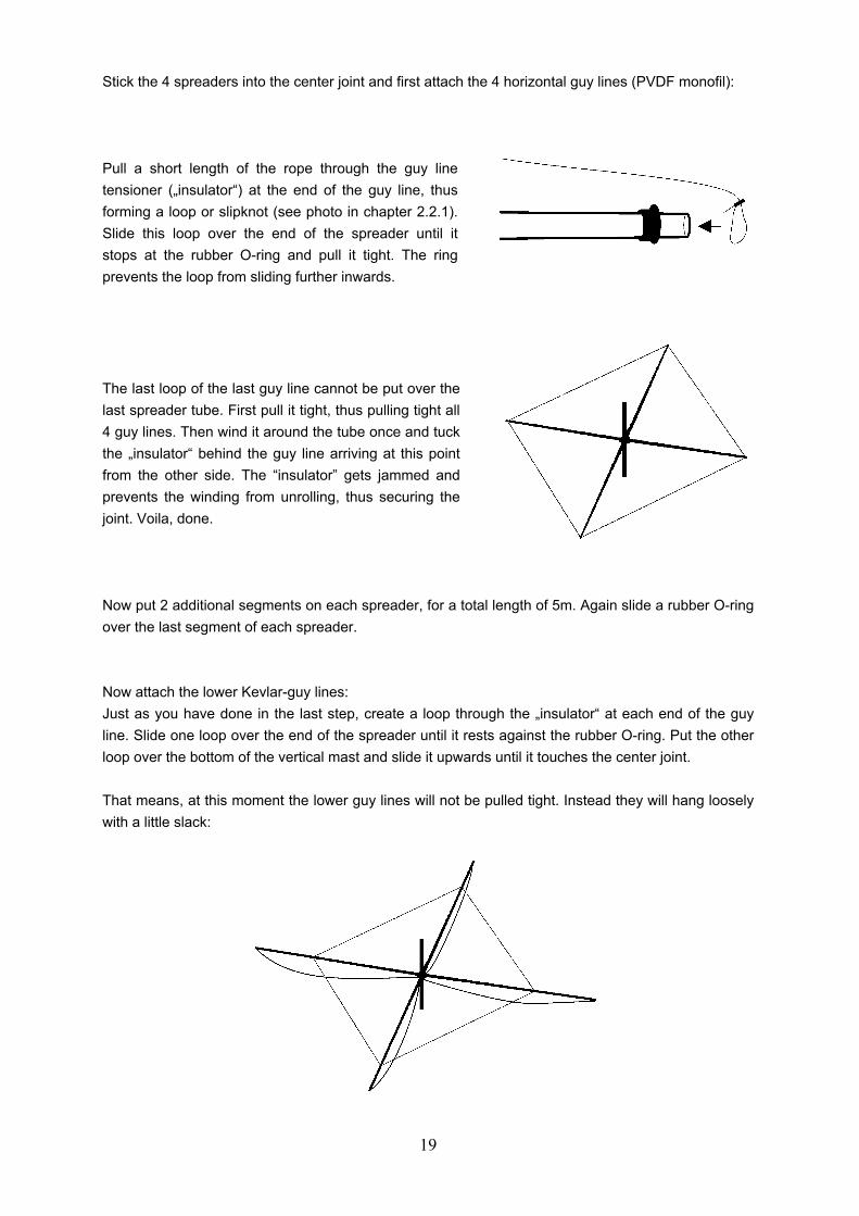
Stick the 4 spreaders into the center joint and first attach the 4 horizontal guy lines (PVDF monofil): Pull a short length of the rope through the guy line tensioner („insulator“) at the end of the guy line, thus forming a loop or slipknot (see photo in chapter 2.2.1). Slide this loop over the end of the spreader until it stops at the rubber O-ring and pull it tight. The ring prevents the loop from sliding further inwards.
The last loop of the last guy line cannot be put over the last spreader tube. First pull it tight, thus pulling tight all 4 guy lines. Then wind it around the tube once and tuck the „insulator“ behind the guy line arriving at this point from the other side. The “insulator” gets jammed and prevents the winding from unrolling, thus securing the joint. Voila, done. Now put 2 additional segments on each spreader, for a total length of 5m. Again slide a rubber O-ring over the last segment of each spreader. Now attach the lower Kevlar-guy lines: Just as you have done in the last step, create a loop through the „insulator“ at each end of the guy line. Slide one loop over the end of the spreader until it rests against the rubber O-ring. Put the other loop over the bottom of the vertical mast and slide it upwards until it touches the center joint. That means, at this moment the lower guy lines will not be pulled tight. Instead they will hang loosely with a little slack:

20
As a last step attach the upper Kevlar guy lines, using exactly the same procedure: create a loop at each end of the line, put one loop over the end of the spreader, put the other loop over the upper end of the vertical mast, done. If you have problems pulling the rope tight enough to put the loop over the vertical mast, here is a hint: Stand behind the vertical mast, so the spreader to be fixed at this moment points away from you. Now push the top of the vertical mast away from you. The spreader will bend upwards, leaving more than enough slack in the guy line to easily slide it over the vertical mast.
Once you have attached all the upper guy lines, it is time to
tension the lower ones: simply slide them downwards
(approx. 40cm) and they will be tensioned.
During the first assembly of the antenna you will probably have to adjust the lengths of the guy lines a
little bit, by moving the guy line tensioners („insulators“) a few centimeters. It seems a good idea to
make the upper guy lines approx 3cm shorter, so the spreaders are bent upwards just slightly.
As a last step, put a sealing rubber cap on the end of each spreader to prevent accumulation of rain water inside the tubes. The basic spider is now assembled. Our next step is to attach the wire elements.

21
3.2. Mounting the Reflector & Director Elements parts necessary: Nr. quantity description
1 Spider, prepared in chapter 3.1. director and reflector wire elements made in chapter 2.3. 7 40cm long double-sided Velcro Straps (20mm wide) made in chapter 2.2.3.
Mounting the Elements fabricated in Chapter 2.3. is really easy. At the first assembly of the antenna you need to decide which pair of fiberglass poles will form the “boom” and which will form the “lateral spreaders”. In chapter 2.2.3. you cut 11cm long (50mm wide) Velcro® Strips. At the first assembly you have to glue them to the boom, at each point where a wire element will be attached (see chapter 2.2.3. and drawing below). Before attaching and tensioning the wire elements it is very helpful to raise the fiberglass spider assembly approx 50cm above ground level, e.g. by mounting it on a short stake driven into the ground. Mounting a wire element: 1. Like in the last chapter, create a loop through the guy line tensioner („insulator“) at the end of each guy line. Put this loop over the end of one spreader until it rests against the rubber O-ring. Pull it tight there. 2. Unroll the wire element.
3. Mount the other end of the wire element at the opposite spreader just as described in 1. 4. Strap the center of the element to the boom, on the 50mm Velcro Strip attached there. I.e. take a 40cm double-sided Velcro strap and wind it crosswise over the wire:
Now the element should be stretched in the form of a V or triangle. Should the lines need adjusting when assembling the antenna for the first time, symmetry should be maintained by ensuring the line lengths are kept equal on both sides.

22
The element attachment points on the boom measured from the center are: band reflector director 1 director 2 20m - 500 cm 500 cm - - - 15m - 260 cm 330 cm - - - 10m - 130 cm 200 cm 420 cm
These distances are not nearly as critical as the wire element lengths! ±10cm or perhaps more is OK. The elements are installed from the inside working outwards, i.e. the 10m reflector and director1 first, followed by 15m etc. Care should be taken not to over tension 'outside' elements to avoid slackening the inner elements 3.3. Mounting the driven Elements parts necessary: Nr. quantity description
driven elements made in chapter 2.4. balun made in chapter 2.5. 2 40cm long double-sided Velcro Straps (20mm wide) made in chapter 2.2.3. 2 70cm long double-sided Velcro Straps (20mm wide) made in chapter 2.2.3.
11 4 M6 nuts, V2A First attach the balun box to the vertical mast. Place the aluminium mounting angle against the mast and strap the ends to the mast, using the 70cm long pieces of double-sided Velcro® band. During the first assembly of the antenna you must of course first glue some 50mm wide Velcro strips to the vertical mast. Mount the balun on the front side of the vertical mast, when looking in forward direction. The feedpoint screws should be at a height of H = 40cm above the center joint plate. Of course you can also mount the balun with hose clamps or the like. But you will be surprised how strong the Velcro keeps it in place and, especially for portable operations the mounting procedure is incredibly fast.
First attach the feed line for the 10m driven element: connect the cable lugs to the bolts extending from the top of the balun box. Let the feedline slope downwards to the boom and attach the center of the driven element to the boom. The distance from the attachment point to the vertical mast should be D = 50 cm. Important N.B.: Pay attention that the feedline is not twisted, i.e. the left feedpoint screw is really connected to the left dipole leg!
feed point

23
To mount the center of the driven element to the boom, stick one of the 40cm long double-sided Velcro straps through the monofilament loop hanging out of the center isolator. Then strap the Velcro band to the boom. During the first assembly of the antenna you have to glue a piece of 50mm wide Velcro to the attachment point on the boom of course. Now stretch the dipole to the end of the spreaders. Attaching the guy line is done a little bit different than usual. Simply wind the end of the guy line one or two times around the pole and then tuck the „insulator“ behind one of the other lines mounted there. It gets jammed and prevents the windings from unrolling, thus securing the joint. Follow the same procedure to mount the 20m driven element. Connect its feedline to the screws extending from the sides of the balun box. Mount the center of the driven element to the boom in a distance of D = - 40cm (backwards). Remember to pay attention, do not twist the feedline! As a last step connect the 15m dipole to the screws protruding from the sides of the balun box as well. String the dipole above the spreaders and attach the guy line to their ends. Congratulations! The assembly is complete – your spider beam is ready to go on the air! Quickly connect a coax cable, mount it to the mast and up it goes...

24
3.4. SWR alignment As mentioned earlier it might be necessary to set the driven element dipoles at resonance in the center of each band: to do so connect an SWR bridge between your transceiver and the antenna and find the frequency of lowest SWR for each band. This is the resonant frequency and you want it to be in the center of your operating band. Anyway, using the dipole lengths specified, resonance SHOULD be at the center of each band already. If it is not, move it by folding or unfolding the short pieces of excess wire at the end of each driven element: if resonance is too low fold the excess wire further back, thus shortening the element. If it is too high, open out the folded wire, thus lengthening the element. Because of mutual coupling the 20m driven element should be adjusted first, followed by 15m and then 10m. When checking SWR alignment it is sufficient to lift the beam 5m off the ground. When finally erecting the antenna to full height the resonant frequency will move slightly higher again but this will not affect performance significantly. An SWR of 2:1 is definitely good enough anyway, especially for short-time (portable) use! SWR alignment of the antenna is normally a quick operation and it should be sufficient to take the antenna up and down only once or twice to complete the task. That’s it. And now, have fun on the air! Where do we go next? Further experimenting is strongly recommended: One advantage of this style of construction is that it is not limited to the tribander described here. Once the supporting structure has been built other wire antenna designs can be tried easily and cheaply. Aside from the wire elements everything remains the same. Depending on the desired goal of the moment you can always tailor-make the optimum antenna to fit your needs. E.g., how about some projects like 6 elements for 6m, 5 elements for 10m in the next 10m contest, a WARC-Beam, 2 elements for 40m…? There are also different concepts regarding the bending of the elements. For example, on the same supporting cross, a Moxon Beam, an X-Beam or a bent HB9CV could be constructed. All you need is an antenna simulation software and a few ideas!
spiderbeam on a 10m aluminium push-up pole

25
4. „Heavy Duty” Version for Fixed Installation Many people wanted to use the Spiderbeam not only temporarily for portable activities, but also in a permanent installation at home. For most fixed installations low antenna weight is a bit less important, but the mechanical design must be strong enough to permanently survive storm and severe weather conditions for many years. Therefore two versions of the antenna were developed: a specially reinforced version optimized for fixed installation, and a lightweight version optimized for portable use. The “Heavy Duty” version gains a lot of extra ruggedness by the following changes to the design:
- specially reinforced fiberglass tubes, double wall thickness (2mm) - center joint constructed with aluminum plates of double wall thickness (2mm) - replacing the Velcro with stainless steel hose clamps with rubber padding - (possible) addition of second upper guy line
No further changes to the antenna are necessary! The weight increases by approx. 5kg. Total weight is 11kg, which is still substantially less than many other 3- or 5-band beams with comparable on-air performance. 4.1. Materials List When Constructing the Heavy Duty Version a few pieces of material are different from those that are listed on page 5. See the following list for the necessary changes: Nr. quantity description 1 20 fiberglass tube segments, length = 1.15m, diameter 30mm, 2mm wall thickness
2 4 aluminium tubes, outer diameter 35mm, wall thickness 2mm, length = 175mm
3 8 aluminium tubes, outer diameter 10mm, wall thickness 1mm, length = 29mm
4 2 aluminium sheet metal, thickness 2mm, length x depth = 220x220mm
17 47 + 15m Kevlar guy line, 1.5mm diameter
19 66 + 8 Plastic - Insulators, black Polyethylene, UV resistant
20 8 Rubber O-Rings (EPDM, UV resistant), 20x6mm
21 1.2m Flat rubber strip (EPDM UV resistant), width = 20mm, thickness = 5mm
22 9 V2A (stainless steel) hose clamps, diameter 25-40mm, width = 9mm
23 2 V2A (stainless steel) hose clamps, diameter 40-60mm, width = 9mm Contrary to the list on page 5, the following pieces are not not needed: 21 5m Double-sided Velcro® Band (Hooks/Loops), Polyester, UV resistant, 20mm wide
22 1.5m Velcro® Band (Loops), Polyester, UV resistant, 50mm wide
23 1 25ml package, 5-Min Epoxid or similar glue (Not needed, because the Velcro for affixing the wire elements to the fiberglass “boom” is replaced by the stainless steel hose clamps) All other quantities remain exactly the same.

26
4.2. Changes during assembly of antenna During the construction of the antenna, only a few small changes need to be made: Constructing the spider center joint (compare chapter 2.1.): The aluminum plates and tubes for the center joint are machined exactly as described in chapter 2.1. The half round cutouts in the 4 tubes of 175mm length can even be omitted. They are not necessary for fixed installation because you will use a vertical mast with a diameter greater than 35mm anyway. Simply assemble the center joint as described in chapter 2.1. Fabricating the Guy Lines (compare chapter 2.2.2): In addition to the 8 Kevlar guy lines of 535cm length described in chapter 2.2.2., fabricate another 4 Kevlar guy lines of 333cm length: Cutting the Velcro® Straps (compare chapter 2.2.3): No Velcro straps have to be cut nor glued to the fiberglass. Instead prepare the hose clamps as follows: Preparing the Stainless Steel Hose Clamps with Rubber Padding (chapter 2.2.3 NEW): parts necessary : Nr. quantity description 21 1.1m Flat rubber strip (EPDM UV resistant), width = 20mm, thickness = 5mm 22 9 V2A (stainless steel) hose clamps, diameter 25-40mm, width = 9mm
Cut the rubber strip in 9 pieces of 12cm length and stick it into the hose clamps:
distance between knots: 8x Kevlar: 535cm – 4x Kevlar: 333cm – 4x Monofil: 461cm

27
Assembling the supporting cross [ spider ] (compare chapter 3.1.): Put together the reinforced fiberglass tube segments exactly as described in chapter 3.1. Afterwards attach the guy lines. In regions with a lot of snow it makes sense to attach a second upper guy line to each spreader. Use the 4 additional Kevlar lines of 333cm and attach as shown in the picture.
The wire elements are mounted exactly as described in chapter 3.2. for the portable version. Instead of the Velcro tape, use the hose clamps with the rubber padding and affix the wire element to the fiberglass boom as shown in the photo: Mounting the Driven Elements (compare chapter 3.3.): The method for attaching the driven elements to the boom is the same: use the hose clamps instead of the Velcro tape. The method for attaching the balun to the mast is the same as well. For attaching the balun, use the larger hose clamps (40-60mm diameter – no rubber padding necessary). Important: When mounting the balun, make sure the symmetric feedlines are not stretched tight! If the feedlines are too tight, slide the balun a few centimeters down the mast, in order to release the tension on the lines. There must be slack on the feedlines, so they are not ripped out of the balun when the fiberglass tubes are flexing in the wind. This is all. No further changes are necessary.
Mounting the Reflector & Director Elements (compare chapter 3.2.):
28
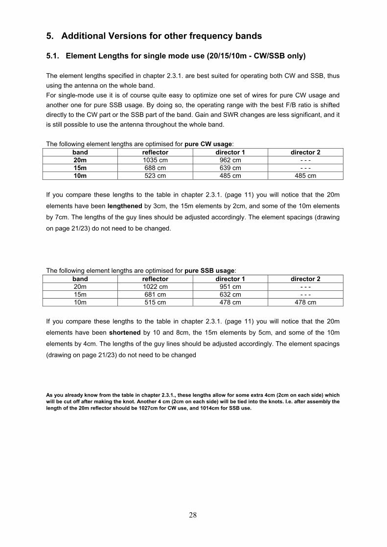
5. Additional Versions for other frequency bands 5.1. Element Lengths for single mode use (20/15/10m - CW/SSB only) The element lengths specified in chapter 2.3.1. are best suited for operating both CW and SSB, thus using the antenna on the whole band. For single-mode use it is of course quite easy to optimize one set of wires for pure CW usage and another one for pure SSB usage. By doing so, the operating range with the best F/B ratio is shifted directly to the CW part or the SSB part of the band. Gain and SWR changes are less significant, and it is still possible to use the antenna throughout the whole band. The following element lengths are optimised for pure CW usage:
band reflector director 1 director 2 20m 1035 cm 962 cm - - - 15m 688 cm 639 cm - - - 10m 523 cm 485 cm 485 cm
If you compare these lengths to the table in chapter 2.3.1. (page 11) you will notice that the 20m
elements have been lengthened by 3cm, the 15m elements by 2cm, and some of the 10m elements
by 7cm. The lengths of the guy lines should be adjusted accordingly. The element spacings (drawing
on page 21/23) do not need to be changed.
The following element lengths are optimised for pure SSB usage:
band reflector director 1 director 2 20m 1022 cm 951 cm - - - 15m 681 cm 632 cm - - - 10m 515 cm 478 cm 478 cm
If you compare these lengths to the table in chapter 2.3.1. (page 11) you will notice that the 20m
elements have been shortened by 10 and 8cm, the 15m elements by 5cm, and some of the 10m
elements by 4cm. The lengths of the guy lines should be adjusted accordingly. The element spacings
(drawing on page 21/23) do not need to be changed
As you already know from the table in chapter 2.3.1., these lengths allow for some extra 4cm (2cm on each side) which will be cut off after making the knot. Another 4 cm (2cm on each side) will be tied into the knots. I.e. after assembly the length of the 20m reflector should be 1027cm for CW use, and 1014cm for SSB use.
29
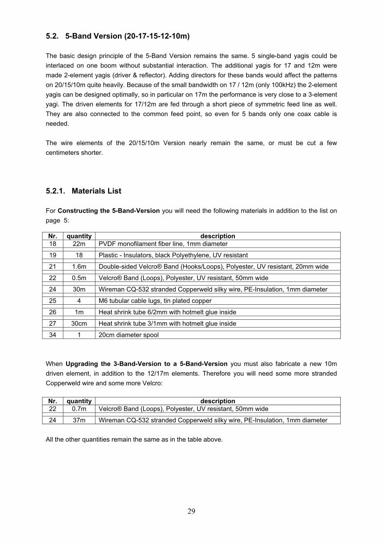
5.2. 5-Band Version (20-17-15-12-10m) The basic design principle of the 5-Band Version remains the same. 5 single-band yagis could be interlaced on one boom without substantial interaction. The additional yagis for 17 and 12m were made 2-element yagis (driver & reflector). Adding directors for these bands would affect the patterns on 20/15/10m quite heavily. Because of the small bandwidth on 17 / 12m (only 100kHz) the 2-element yagis can be designed optimally, so in particular on 17m the performance is very close to a 3-element yagi. The driven elements for 17/12m are fed through a short piece of symmetric feed line as well. They are also connected to the common feed point, so even for 5 bands only one coax cable is needed. The wire elements of the 20/15/10m Version nearly remain the same, or must be cut a few centimeters shorter. 5.2.1. Materials List For Constructing the 5-Band-Version you will need the following materials in addition to the list on page 5: Nr. quantity description 18 22m PVDF monofilament fiber line, 1mm diameter
19 18 Plastic - Insulators, black Polyethylene, UV resistant
21 1.6m Double-sided Velcro® Band (Hooks/Loops), Polyester, UV resistant, 20mm wide
22 0.5m Velcro® Band (Loops), Polyester, UV resistant, 50mm wide
24 30m Wireman CQ-532 stranded Copperweld silky wire, PE-Insulation, 1mm diameter
25 4 M6 tubular cable lugs, tin plated copper
26 1m Heat shrink tube 6/2mm with hotmelt glue inside
27 30cm Heat shrink tube 3/1mm with hotmelt glue inside
34 1 20cm diameter spool When Upgrading the 3-Band-Version to a 5-Band-Version you must also fabricate a new 10m driven element, in addition to the 12/17m elements. Therefore you will need some more stranded Copperweld wire and some more Velcro: Nr. quantity description 22 0.7m Velcro® Band (Loops), Polyester, UV resistant, 50mm wide
24 37m Wireman CQ-532 stranded Copperweld silky wire, PE-Insulation, 1mm diameter All the other quantities remain the same as in the table above.
30
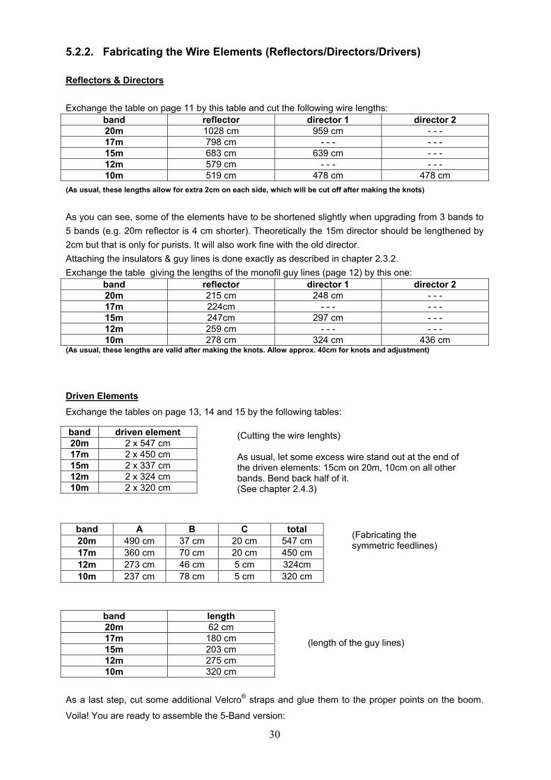
5.2.2. Fabricating the Wire Elements (Reflectors/Directors/Drivers) Reflectors & Directors Exchange the table on page 11 by this table and cut the following wire lengths:
band reflector director 1 director 2 20m 1028 cm 959 cm - - - 17m 798 cm - - - - - - 15m 683 cm 639 cm - - - 12m 579 cm - - - - - - 10m 519 cm 478 cm 478 cm
(As usual, these lengths allow for extra 2cm on each side, which will be cut off after making the knots)
As you can see, some of the elements have to be shortened slightly when upgrading from 3 bands to 5 bands (e.g. 20m reflector is 4 cm shorter). Theoretically the 15m director should be lengthened by 2cm but that is only for purists. It will also work fine with the old director. Attaching the insulators & guy lines is done exactly as described in chapter 2.3.2. Exchange the table giving the lengths of the monofil guy lines (page 12) by this one:
band reflector director 1 director 2 20m 215 cm 248 cm - - - 17m 224cm - - - - - - 15m 247cm 297 cm - - - 12m 259 cm - - - - - - 10m 278 cm 324 cm 436 cm
(As usual, these lengths are valid after making the knots. Allow approx. 40cm for knots and adjustment)
Driven Elements Exchange the tables on page 13, 14 and 15 by the following tables:
As a last step, cut some additional Velcro® straps and glue them to the proper points on the boom.
Voila! You are ready to assemble the 5-Band version:
band driven element 20m 2 x 547 cm 17m 2 x 450 cm 15m 2 x 337 cm 12m 2 x 324 cm 10m 2 x 320 cm
band A B C total 20m 490 cm 37 cm 20 cm 547 cm 17m 360 cm 70 cm 20 cm 450 cm 12m 273 cm 46 cm 5 cm 324cm 10m 237 cm 78 cm 5 cm 320 cm
band length 20m 62 cm 17m 180 cm 15m 203 cm 12m 275 cm 10m 320 cm
(Cutting the wire lenghts) As usual, let some excess wire stand out at the end of the driven elements: 15cm on 20m, 10cm on all other bands. Bend back half of it. (See chapter 2.4.3)
(Fabricating the symmetric feedlines)
(length of the guy lines)

31
5.2.3. Assembly Drawings for the 5-Band Version
Assembly is done exactly as described in Chapter 3, and the distance of the elements are as follows: Attachment points of elements on boom, measured from antenna center:
band reflector director 1 director 2 driver 20m - 500 cm 500 cm - - - - 40 cm 17m - 330 cm - - - - - - - 80 cm 15m - 260 cm 330 cm - - - - - - 12m - 150 cm - - - - - - 40 cm 10m - 110 cm 200 cm 420 cm 80 cm
Once again the balun is mounted 40cm above the center plate, in front of the vertical mast (when viewed in forward direction). The feedlines for 10 and 12m are connected to the screws protruding from the top of the balun box. The feedlines for 17 and 20m and the 15m dipole legs are connected to the screws protruding from the sides of the balun box. The driver centers are attached to the boom from back to front in the following order: 17m – 20m – 12m – 10m. As usual, pay attention not to twist the symmetric feedlines! As a last step, connect the 15m dipole to the balun and string it to the ends of the spreaders. If SWR alignment is necessary, do it in the following order: 20-17-15-12-10m.
32
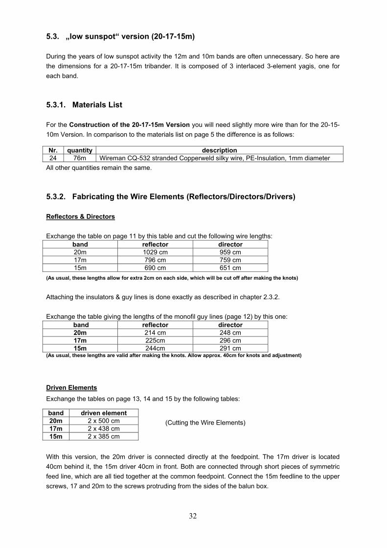
5.3. „low sunspot“ version (20-17-15m) During the years of low sunspot activity the 12m and 10m bands are often unnecessary. So here are the dimensions for a 20-17-15m tribander. It is composed of 3 interlaced 3-element yagis, one for each band. 5.3.1. Materials List For the Construction of the 20-17-15m Version you will need slightly more wire than for the 20-15-10m Version. In comparison to the materials list on page 5 the difference is as follows: Nr. quantity description 24 76m Wireman CQ-532 stranded Copperweld silky wire, PE-Insulation, 1mm diameter
All other quantities remain the same. 5.3.2. Fabricating the Wire Elements (Reflectors/Directors/Drivers) Reflectors & Directors Exchange the table on page 11 by this table and cut the following wire lengths:
band reflector director 20m 1029 cm 959 cm 17m 796 cm 759 cm 15m 690 cm 651 cm
(As usual, these lengths allow for extra 2cm on each side, which will be cut off after making the knots)
Attaching the insulators & guy lines is done exactly as described in chapter 2.3.2. Exchange the table giving the lengths of the monofil guy lines (page 12) by this one:
band reflector director 20m 214 cm 248 cm 17m 225cm 296 cm 15m 244cm 291 cm
(As usual, these lengths are valid after making the knots. Allow approx. 40cm for knots and adjustment)
Driven Elements Exchange the tables on page 13, 14 and 15 by the following tables:
With this version, the 20m driver is connected directly at the feedpoint. The 17m driver is located 40cm behind it, the 15m driver 40cm in front. Both are connected through short pieces of symmetric feed line, which are all tied together at the common feedpoint. Connect the 15m feedline to the upper screws, 17 and 20m to the screws protruding from the sides of the balun box.
band driven element 20m 2 x 500 cm 17m 2 x 438 cm 15m 2 x 385 cm
(Cutting the Wire Elements)

33
As usual, let some excess wire stand out at the end of the driven elements: 15cm on 20m, 10cm on all other bands. Bend back half of it. (See chapter 2.4.3)
5.3.3. Assembly drawings
Attachment points of elements on boom, measured from antenna center: band reflector director driver 20m - 500 cm 500 cm 0 cm 17m - 330 cm 420 cm - 40 cm 15m - 260 cm 330 cm 40cm
band A B C total 17m 381 cm 37 cm 20 cm 438 cm 15m 328 cm 52 cm 5 cm 385 cm
band length 20m 46 cm 17m 160 cm 15m 211 cm
(Fabricating the Symmetric feed lines)
(length of the guy lines)

34
5.4. WARC Version (30-17-12m) Similar to the 20-15-10m version, the WARC spiderbeam is composed of 3 interlaced yagis for the WARC bands: a 3-element yagi for 30m, a 3-element yagi for 17m, and a 4-element yagi for 12m. The dimensions specified in this chapter have not yet been verified in a test setup. From the experience gained with the antennas built so far, they should be right with a probability of 90%. Hello experimenters, who builds the first version?
5.4.1 Materials List For the Construction of the 30-17-12m Version you will need slightly more wire than for the 20-15-10m Version. You will also need 4 additional fiberglass tube segments, because the spreaders are 6m long instead of 5m. You will need some extra Kevlar for the additional upper Kevlar guy lines (see below). In comparison to the materials list on page 5 the difference is as follows: Nr. quantity description 24 91m Wireman CQ-532 stranded Copperweld silky wire, PE-Insulation, 1mm diameter 17 70m Kevlar guy line, 1.5mm diameter 19 74 Plastic - Insulators, black Polyethylene, UV resistant
All other quantities remain the same. 5.4.2 Fabricating & Attaching the Guy lines Similar to the description in chapter 2.2.2., fabricate 8 Kevlar guy lines of 638cm length, and 4 PVDF Monofil guy lines of 461cm length. Additionally fabricate another 4 Kevlar guy lines of 340cm length. Use them to attach a second upper guy line to each spreader (see picture below). If possible, use a somewhat longer vertical mast with these 6m long spreaders, and let it protrude 80 -100cm above the antenna. The longer mast makes for a better angle when attaching and tightening the guy lines.
distance between knots: 8x Kevlar: 638cm – 4x Kevlar: 340cm – 4x Monofil: 461cm

35
5.4.3. Fabricating the Wire Elements (Reflectors/Directors/Drivers) Reflectors & Directors Exchange the table on page 11 by this table and cut the following wire lengths:
band reflector director 1 director 2 30m 1417 cm 1370 cm - - - 17m 793 cm 762 cm - - - 12m 587cm 551 cm 544 cm
(As usual, these lengths allow for extra 2cm on each side, which will be cut off after making the knots)
Attaching the insulators & guy lines is done exactly as described in chapter 2.3.2. Exchange the table giving the lengths of the monofil guy lines (page 12) by this one:
band reflector director 1 director 2 30m 161 cm 185 cm - - - 17m 298 cm 356 cm - - - 12m 360 cm 391 cm 518 cm
(As usual, these lengths are valid after making the knots. Allow approx. 40cm for knots and adjustment)
Driven Elements
Exchange the tables on page 13, 14 and 15 by the following tables:
With this version, the 17m driver is connected directly at the feedpoint. The 30m driver is located 40cm behind it, the 12m driver 40cm in front. As usual, both are connected through short pieces of symmetric feed line, which are all tied together at the common feedpoint. Connect the 12m feedline to the upper screws, 17 and 30m to the screws protruding from the sides of the balun box.
As usual, let a 10cm length of excess wire stand out at the end of the 12m and 17m driven elements,
then bend back half of it. (See chapter 2.4.3). For the 30m driver, see below.
The driven element for 30m is approx. 1m longer than the 6m long spreaders. Therefore no guy line is
needed. Simply attach the wire to the end of the spreader with a cable tie or similar, and let the rest of
the wire hang down. Bend back the usual 10 or 15cm for SWR adjustment.
band driven element 30m 2 x 731 cm 17m 2 x 386 cm 12m 2 x 330 cm
band A B C total 30m 674cm 37 cm 20 cm 731 cm 12m 273cm 52 cm 5 cm 330 cm
band length 30m --- 17m 257 cm 12m 367 cm
(Fabricating the Symmetric feed lines)
(length of the guy lines)
(Cutting the Wire Elements)

36
5.4.4. Assembly drawings
Attachment points of elements on boom, measured from antenna center: band reflector director 1 director 2 driver 30m - 600 cm 600 cm - - - - 40 cm 17m - 300 cm 390 cm - - - 0 cm 12m - 190 cm 230 cm 480 cm 40 cm