Embed Size (px)
Citation preview
400540
Spider����
Operator’s Manual
Operation ••••
Assembly ••••
Service ••••
Inspection ••••
Spider� Operator’s Manual 400540
2 © Spider�, A Division of SafeWorks, LLC.
Contents Safety notices, cautions......................................3
Code of safe practices ........................................5
General operating instructions ............................8
Staging equipment
Models ST-17/ST-17-1, ST-18/ST-18-1................8
Models ST-19A & ST-19E....................................8
Models ST-26 & ST-26E......................................9
Models ST-27 & ST-27-1 ....................................10
Wire rope inspection & service
Wire rope guide.................................................12
Wire rope tensioning clamp ................................13
Tension holder...................................................13
Wire rope drum & automatic emergency brake ....14
Wire rope level wind system...............................14
Transmission .....................................................15
Overload switch .................................................15
Motor control switch ..........................................16
Electric hoist......................................................17
Air hoist ............................................................19
Accessory equipment
Safety equipment ..............................................20
Arc guards.........................................................21
Fly decks...........................................................21
Demountable fly decks .......................................22
Swing stage platforms........................................23
Ladder-type aluminum planks.............................24
Rail Clamps .......................................................26
Rollers ..............................................................26
Ground dolly......................................................27
Rigging equipment
Cable clamps..................................................... 28
Caster assembly ................................................ 28
Channel beam hook ........................................... 28
Corner adapter .................................................. 28
End adapter stirrup............................................ 29
End gate ........................................................... 29
Hinge................................................................ 30
I-beam roller ..................................................... 30
Modular platform ............................................... 31
Outriggers......................................................... 31
Rigging hook ..................................................... 34
Roof hooks........................................................ 34
Shackle ............................................................. 35
Stirrup .............................................................. 35
Tank top rollers ................................................. 36
Transfer chain ................................................... 36
Wire rope insulator ............................................ 36
Wire rope inspection report ................................ 38
Due to continuing product improvement, the information in this document is subject to change without notice. Spider shall not be
held liable for technical or editorial omissions made herein, nor for any incidental or consequential damage resulting from the use of this material.
This document contains material protected by copyright laws. No part of this document shall be reproduced in any manner without prior written consent from Spider. Spider is a division of SafeWorks, LLC.
© 1988-1997 Spider�
400540 Spider� Operator’s Manual
© Spider�, A Division of SafeWorks, LLC. 3
CAUTION Hazardous Working Environment
This equipment is used off the ground in high or dangerous places. Anyone using this equipment is exposed to a hazardous working environment.
Users must be properly trained in the use and rigging of this
equipment and be familiar with all applicable local, state, and federal codes; safety rules and regulations pertaining to single
and two-point suspension scaffolding; general safety and health provisions; and personal protective and lifesaving
equipment.
The Scaffolding shall be properly assembled according to
instructions available from your Spider representative. Guardrails, midrails, and toeboards shall be used as required
by local, state, and federal regulations. Their use is recommended in all cases. The working surface shall be level
at all times.
This equipment should not be used by persons affected by (but not limited to) the following: ill health, not of sound mind
or body, under the influence of alcohol or drugs, acrophobia,
arachnophobia, epilepsy, fainting spells, suicidal tendency, despondency, or prone to accidents. Safety lines and
harnesses shall be used in accordance with federal and state law.
Neither the manufacturer nor its distributors can know of,
anticipate, or warn against all dangers that exist or can ever arise. Be alert to recognize all dangers, known and unknown.
Oil, grease, slippery material, or unstable objects such as barrels, boxes, loose bricks, tools, or debris shall not be
allowed to accumulate on work surfaces. Do not use the product if the decking surface is damaged or has deteriorated.
Coat wood decking periodically with a wood preservative. Do not paint.
Do not place ladders or other devices on the scaffold to gain
greater height. Never climb on to stages from a ladder, unless both the stage and the ladder are secured from moving in all
directions. Do not use platform to transfer workers. Do not
store tools, materials, or equipment on planks or platforms that are being moved.
The equipment can be seriously weakened by many things,
including (but not limited to): improper, inadequate, or incomplete assembly; fire; acid or other corrosive substances;
contact with electrical circuits; corrosion; electrolysis; weather; careless handling or maintenance; missing parts; improper
usage or rigging; improper, inadequate, or incomplete repairs or replacements; damage in any way; exceeding the load
limits.
Do not use metal platforms near electrical circuits.
Do not use acids or corrosives on platforms without consulting
the platform manufacturer. Consult the acid supplier or manufacturer for effects on aluminum, steel, zinc, or wood
components of scaffold and have the prescribed neutralizer in hand.
Thoroughly inspect all parts and fasteners as often as possible. Inspect the equipment often for damage, corrosion, loose or
missing parts, improper assembly, and wear.
Do not use damaged or improperly functioning scaffolds. Do not apply impact loads to plank or platform. Never attempt to
straighten deformed side rails or deck members. Do not use
this equipment if bent, broken, damaged, or weakened in any
way.
If an inspection finds a condition you are doubtful of or do not
understand, consult your employer or the manufacturer or his authorized repair and maintenance representative. Remove
weakened or damaged equipment from service immediately. Do not repair or make modifications to equipment without
manufacturer’s written authorization.
Platforms and stages are designed with a rated working load of 250, 500, or 750 pounds. The total combined weight of
workers and materials shall not exceed the rated working load. Do not overload. Do not apply impact loads to platform. If the
platforms are exposed to excessive heat as in the case of fire,
the product shall be immediately removed from service and destroyed due to loss of structural strength.
Improper use, treatment, or maintenance of this equipment
can result in injury to or death of the user or others in the area.
IMPORTANT – READ! Selected portions of federal OSHA standards have been
reproduced in this manual for the convenience of Spider users. Spider assumes no responsibility for their accuracy,
completeness or timeliness; or other conflicting codes enforced in the location of application. Obtain complete standards from
the nearest office of the Department of Labor. Users should also review applicable state or local codes or regulations
pertaining to general safety or use of this equipment. OSHA Requirements from Safety and Health Regulations for Construction. Vol. 37, No. 243, Part II: 1926.20 General Safety and Health Provisions (a) Contractor requirements.
1. Section 107 of the Act requires that it shall be a condition of each contract which is entered into under
legislation subject to Reorganization Plan Number 14 of
1950 (64 Stat. 1267), as defined in 1926.12, and is for construction, alteration, and/or repair, including
painting and decorating, that no contractor or subcontractor for any part of the contract work shall
require any laborer or mechanic employed in the performance of the contract to work in surroundings or
under working conditions which are unsanitary, hazardous, or dangerous to his health or safety.
(b) Accident-prevention responsibilities 1. It shall be the responsibility of the employer to initiate
and maintain such programs as may be necessary to comply with this part.
2. Such programs shall provide for frequent and regular inspections of the job sites, materials, and equipment
to be made by competent persons designated by the employers.
3. The use of any machinery, tool, material, or equipment that is not in compliance with any applicable
requirement of this part is prohibited. Such machine,
tool, material, or equipment shall either be identified as unsafe by tagging or locking the controls to render then
inoperable or shall be physically removed from its place of operation.
4. The employer shall permit only those employees qualified by training or experience to operate
equipment and machinery.

Spider� Operator’s Manual 400540
4 © Spider�, A Division of SafeWorks, LLC.
1926.21 Safety Training and Education (a) General requirements. The Secretary shall, pursuant to
Section 107(f) of the ACT, establish and supervise
programs for the education and training of employers and employees in the recognition, avoidance and
prevention of unsafe conditions in employments covered by the act.
(b) Employer Responsibility. 1. The employer should avail himself of the safety and
health and training programs the Secretary provides.
2. The employer shall instruct each employee in the recognition and avoidance of unsafe conditions and the
regulations applicable to his work environment to control or eliminate any hazards or other exposure to
illness or injury. 3. Employees required to handle or use poisons, caustics,
and other harmful substances shall be instructed regarding the safe handling and use, and be made
aware of the potential hazards, personal hygiene, and personal protective measures required.
1926.28 Personal protective equipment (a) The employer is responsible for requiring the wearing
of appropriate personal protective equipment in all
operations where there is an exposure to hazardous conditions or where this section indicates the need for
using such equipment to reduce hazards to employees. (b) Regulations governing the use, selection, and
maintenance of personal protective and lifesaving
equipment are described under Subpart E below.
Subpart E Section 1926.104 Safety belts, lifelines, and lanyards (a) Lifelines, safety belts, and lanyards shall be used only
for employee safeguarding. Any lifeline, safety belt, or
lanyard actually subjected to in-service loading, as distinguished from static load testing, shall be
immediately removed from service and shall not be used again for employee safeguarding.
(b) Lifelines shall be secured above the point of operation to an anchorage or structural member supporting a
minimum dead weight of 5,400 lbs. (c) Lifelines used on rock-scaling operations, or in areas
where lifeline may be subjected to cutting or abrasion, shall be a minimum of 7/8-inch wire core manila rope.
For all other lifeline applications, a minimum of ¾-inch manila or equivalent, with a minimum breaking
strength of 5,400 pounds shall be used.
(d) Safety belt lanyard shall be a minimum of ½-inch nylon, or equivalent, with a maximum length to provide
for a fall of no greater than 6 feet. The rope shall have a nominal breaking strength of 5,400 lbs.
(e) All safety belt and lanyard hardware shall be dropped forged or pressed steel, cadmium plated in accordance
with Type 1, Class B plating specified in Federal Specification QQ-P-416. Surface shall be smooth and
free of sharp edges. (f) All safety belt and lanyard hardware, except rivets,
shall be capable of withstanding a tensile loading of 4,000 pounds without cracking, breaking, or
permanently deforming.
Volume 39, Number 125, Part II: Subpart D 1910.28 Safety requirements for scaffolding (a) General requirements for all scaffolds.
4. Scaffolds and their components shall be capable of supporting without failure at least four times the
maximum intended load. 6. Any scaffold damaged or weakened from any cause
shall be immediately repaired and shall not be used until repairs have been completed.
7. Scaffolds shall not be loaded in excess of the working
load for which they are intended. 15. Materials being hoisted onto a scaffold shall have a tag
line. 16. Overhead protection shall be provided for workers on a
scaffold exposed to overhead hazards. 17. Scaffolds shall be provided with a screen between the
toeboard and the guardrail extending along the entire opening, consisting of 18 gauge U.S. standard wire ½-
in. mesh or the equivalent, where persons are required to work or pass under the scaffold.
18. Employees shall not work on scaffolds during storms or high winds.
19. Employees shall not work on scaffolds that are covered in ice or snow, unless all ice or snow is removed and
planking sanded to prevent slipping. 20. Tools, materials, and debris shall not be allowed to
accumulate in quantities to cause hazard. 22. Wire or fiber rope used for scaffold suspension shall be
capable of supporting at least 6 times the intended
load. 27. Special precautions shall be taken to protect scaffold
members, including any wire or fiber ropes, when using a heat-producing process.
G. Two-point suspension scaffolds (swinging scaffolds).
4. The roof irons or hooks shall be of wrought iron, mild steel, or other equivalent material of proper size and
design, securely installed and anchored. The tie-backs of ¾-inch manila rope (or the equivalent) shall serve as
a secondary means of anchorage, installed at right angles to the face of the building whenever possible
and secured to a structurally sound portion of the building.
5. Guardrails not less than 2x4 in. or the equivalent & not less 36 in. or more than 42 in. high, with a midrail,
when required, 1x4 in. lumber or equivalent, and toe-boards, shall be installed at all open sides on all
scaffolds more than 10 ft. above the ground or floor.
Toeboards shall be a minimum of 4 in. high. Wire mesh shall be installed in accordance with paragraph (a)(17).
6. Two-point suspension scaffolds shall be suspended by wire rope or fiber ropes. Wire and fiber roped shall
conform to paragraph (a)(22) of this section. 8. All wire ropes, fiber ropes, slings, hangers, platforms,
and other supporting parts shall be inspected before every installation. Periodic inspections shall be made
while the scaffold is in use. 9. On suspension scaffolds designed for a working load of
500 lbs, no more than two workers shall be permitted to work at one time. On suspension scaffolds with a
working load of 750 lbs, no more than 3 workers shall be permitted to work at one time. Each worker shall be
400540 Spider� Operator’s Manual
© Spider�, A Division of SafeWorks, LLC. 5
protected by a safety lifebelt attached to a lifeline. The
lifeline shall be securely attached to substantial members of the structure (not scaffold), or to securely
rigged lines, which will safely suspend the worker in case of a fall.
10. Where acid solutions are used, fiber ropes are not permitted unless acid-proof.
11. Two-point suspension scaffolds shall be securely lashed of the building or structure to prevent them from swaying. Window cleaners’ anchors shall not be used
for this purpose.
I. Single-point adjustable suspension scaffolds. 8. The hoisting machines, cables, and equipment shall be
regularly serviced and inspected after each installation and every 30 days thereafter.
9. The units may be combined to form a two-point suspension scaffold. Such scaffold shall comply with
paragraph (g) of this section. 10. The supporting cable shall be straight for it’s entire
length, and the operator shall not sway the basket and fix the cable to any intermediate points to change his
original path of travel. 11. Equipment shall be maintained and used in accordance
with the manufacturers’ instructions,
12. Suspension methods shall conform to applicable provisions of paragraph (g) and (h) of this section.
Code of safe practices for suspended powered scaffolds It shall be the responsibility of all employers and users to read
and comply with the following common-sense guidelines, which are designed to promote safety in the erection and use
of suspended powered scaffolds. These guidelines are not all-inclusive, nor do they supplant or replace other additional
safety and precautionary measures to cover usual and unusual conditions. If these guidelines conflict in anyway with state,
local, or federal statute or governmental regulation, said state statute or regulation shall supersede these guidelines, and it
shall be the responsibility of each employer and user to comply
therewith and also to be knowledgeable and understand all state, local or federal statutes or governmental regulations
pertaining to suspended powered scaffolding.
I. General guidelines 1. Post these safety guidelines in a conspicuous place and
be sure that all persons who erect, use, locate, or dismantle suspended scaffold systems are fully aware
of them. 2. NEVER TAKE CHANCES! If in doubt regarding safety or
use of suspended scaffolds, consult your scaffold supplier.
3. FOLLOW ALL EQUIPMENT MANUFACTURERS’ RECOM-MENDATIONS, as well as state, local, and federal
codes, ordinances, and regulations, pertaining to suspended scaffolding.
4. Survey the job site for hazards such as exposed
electrical wires, obstructions that could overload or tip the suspended scaffold when it is raised or lowered,
unguarded roof edges or openings, inadequate or
missing tieback anchorages, or the need for overhead
protection where exposure to falling objects exists. These conditions must be corrected before installing or
using suspended powered scaffold systems. 5. INSPECT ALL EQUIPMENT BEFORE EACH USE. Never
use any equipment that is damaged or defective in any way. Tag damaged or defective equipment and remove
it from the job site.
6. ALWAYS USE FALL-ARREST EQUIPMENT when using suspended scaffolds. (See Section E.)
7. Erect, use, and dismantle, or alter suspended powered scaffold equipment in accordance with design and/or
manufacturer’s recommendations. 8. Do not erect, dismantle, or alter suspended scaffold
systems unless under the supervision of a qualified person.
9. DO NOT ABUSE, MISUSE, OR USE SUSPENDED SCAFFOLD EQUIPMENT for purposes or in ways for
which it was not intended. 10. USERS MUST BE TRAINED on how to safely operate
equipment and how to handle emergency situations. If in doubt, consult a qualified person.
11. ERECTED SUSPENDED SCAFFOLDS SHOULD BE CONTINUOUSLY INSPECTED by the user to ensure that
they are maintained in a safe condition. Report any
unsafe condition to your supervisor. 12. CARE MUST BE TAKEN WHEN OPERATING AND STOR-
ING EQUIPMENT DURING WINDY CONDITIONS. 13. POWERED PLATFORMS MUST NEVER BE OPERATED
NEAR LIVE POWER LINES unless proper precautions are taken. Consult the power service company for
advise. 14. DO NOT WORK ON SCAFFOLDS if you feel dizzy, un-
steady in any way, or are impaired in any way by drugs or any other substance.
II. Rigging guidelines 1. WHEN RIGGING ON EXPOSED ROOFS OR FLOORS,
WEAR FALL-PROTECTION EQUIPMENT. WHEN RIGG-
ING FROM OVERHEAD SUPPORTS, SUCH AS BRIDGES OR BEAMS, WEAR FALL-ARREST EQUIPMENT.
2. Roof hooks, parapet clamps, outrigger beams, or other
supporting devices, including tiebacks and their anchorages, must be capable of supporting the rated
load of the hoist with a safety factor of 4. 3. Verify that the building or structure will support the
suspended loads with a safety factor of at least 4. 4. Overhead rigging, including counterweights, must be
secured from unintentional movement in any direction. 5. Counterweights used with outrigger beams must be of
non-flowable material and fastened to the beam. 6. Outrigger beams that do not use counterweights must
be installed and secured on the roof structure with devices specifically designed for that purpose.
7. Tie back all transportable rigging devices with wire rope and hardware that has strength equal to the hoist rope.
8. Install tiebacks at right angles to the face of the building and secure without slack to a structurally
sound portion of the building. 9. RIG SO THAT SUSPENSION POINTS ARE DIRECTLY
ABOVE THE HOISTING MACHINES.
10. The platform must be secured to prevent swaying. Do not tie it to window cleaning anchors.

Spider� Operator’s Manual 400540
6 © Spider�, A Division of SafeWorks, LLC.
III. Wire rope and hardware guidelines 1. Use only wire rope and attachments as specified by the
hoisting machine manufacturer. Do not use wire rope that is kinked, birdcaged, corroded, undersized, or
damaged in any way. 2. Be sure that wire rope is long enough to reach the
lowest possible landing.
3. Clean, lubricate & handle wire rope in accordance with wire rope or hoist manufacturer’s instructions.
4. Coil and uncoil wire rope in accordance with the wire rope or hoist manufacturer’s instruction in order to
avoid kinks or damage. 5. Use thimbles at all wire rope suspension terminations.
6. Use J-type clamps or swaged fittings to fasten wire rope. DO NOT USE U-CLAMPS.
7. Tighten wire rope clamps in accordance with the clamp manufacturer’s instructions.
8. Wire ropes used in traction hoists must have prepared ends in accordance with the manufacturer’s
recommendation. 9. INSPECT WIRE ROPE DURING EACH ASCENT AND
DESCENT. Do not expose wire rope to fire, undue heat, corrosive atmosphere, chemicals, to passage of
electrical currents, or to damage by tools or handling.
IV. Power supply guidelines 1. BE SURE YOUR POWER SUPPLY CONFORMS TO HOIST
MANUFACTURER’S RECOMMENDATIONS.
2. GROUND ALL ELECTRICAL POWER SOURCES and POWER CORD CONNECTIONS. Protect with circuit
breakers. 3. Use power cords or air hoses of proper size that are
long enough for the job. 4. Power cord or air hose connections must be restrained
to prevent their separation. 5. Tie off power cords or air hoses at the suspended
scaffold to prevent them from falling. 6. Protect power cords or air hoses at sharp edges.
7. Remember, air hoist require clean, lubricated air.
V. Fall-arrest equipment guidelines 1. Each person on a suspended powered scaffold must be
attached to a fall-arrest system at all times.
2. Each lifeline must be fastened to a separate anchorage. 3. When wrapping lifelines around structural members,
the lines must be protected and a suitable anchorage system must be used.
4. Protect lifelines at sharp corners to prevent chafing. 5. Rig fall-arrest systems to prevent a free fall in excess of
6 ft. 6. Lifelines must be suspended freely without contact with
structural members or building façade. 7. Use a lifeline size and construction that is compatible
with fall arrester and complies with applicable safety codes.
8. BE SURE FALL ARRESTER IS INSTALLED ON THE LIFELINE IN THE PROPER DIRECTION ABOVE YOUR
HEAD and in accordance with the manufacturer’s
recommendations. 9. Use a body-support device that is properly sized and
fitted.
10. Be sure the body-support device has a lanyard attached to the D-ring at the center of the back.
VI. Additional guidelines 1. USE ALL EQUIPMENT AND ALL DEVICES IN ACCORD-
ANCE WITH THE MANUFACTURER’S INSTRUCTIONS. 2. Do not overload, modify, or substitute equipment.
3. Before commencing work operations, pre-load wire
rope and equipment with the maximum working load, and then retighten rigging clamps to manufacturer’s
recommendations. 4. Be sure platform and cages have a proper guardrail
system. 5. Secure stirrups no less than six inches from the end of
the platform. 6. All components must be securely fastened to prevent
them from falling off the platform. 7. Use roller bumpers or buffers to prevent damage to the
structure or equipment. 8. Use care to prevent damage to equipment by corrosive
or other damaging substances. 9. Clean and service equipment regularly.
10. ALWAYS MAINTAIN AT LEAST FOUR (4) WRAPS OF ROPE ON DRUM-TYPE HOISTS.
11. Traction hoists must have wire rope that is long enough to reach from the highest point of support to the lowest
possible landing, plus reeving lengths.
12. Do not join platforms unless the installation was designed for that purpose.
13. DO NOT MOVE SUSPENDED SCAFFOLDS HORIZ-ONTALLY WHEN OCCUPIED.
14. When re-rigging for another drop, be sure sufficient wire rope is available before moving the suspended
scaffold system horizontally. 15. WHEN WELDING FROM SUSPENDED SCAFFOLDS:
• Be sure platform is grounded to structure.
• Insulate wire rope above and below the platform
to protect from damage by the welding torch or electrode.
• Insulate wire rope at suspension point and be sure wire rope does not contact structure along its
entire length.

400540 Spider� Operator’s Manual
© Spider�, A Division of SafeWorks, LLC. 7
General operating instructions 1. Assemble the scaffold and rigging equipment according to
the instructions in this manual or those supplied with the
equipment. (Refer to the precautions in the preceding sections.)
2. All rigging devices and installations must be able to support the load. An engineer or someone who is trained
and capable of determining whether the structure is large enough and strong enough to bear the load should
examine structural members. The structure must be able to bear a wire rope load of 4 times the maximum rated
load capacity of the hoist. The gross load of equipment, material, and the workers being lifted by each wire rope
must not exceed the rated load capacity of the hoist. The structural members intended to support the load must not
have cracked or weakened material. 3. Examine the structure for other safety hazards.
• Remove obstructions to vertical travel, or clearly
identify them to equipment users. • De-energize and lock out electrical lines in & near the
path traveled by the equipment. No live power lines
are allowed within 10 ft. of the scaffolding or scaffolding extension.
• Locate cranes or other lifts. All equipment users
should know the location of all other workers on the structure to avoid coming in contact with them.
• Identify and remove other hazards, such as the
danger of falling material. 4. Assemble the rigging device to the structure so the
suspension line hangs plumb and passes through the scaffold equipment wire rope guide. If the wire rope is
pulled off at an angle from the guide, it could wear and become weak.
5. Provide separate rigging attachments for worker safety lines in case the suspension line rigging fails.
6. With the scaffolding equipment resting upright on the ground directly under the rigging points, connect it to the
proper power supply. Place the fairlead side (front) toward the face of the structure. This provides greater stability
and minimizes the amount of thrust-out required by the
outrigger. 7. Release the tension holder by pulling the handle up.
8. Operate the DOWN switch while pulling the wire rope off the drum and through the guide.
CAUTION Keep hands and other parts of the body away from wire rope guide assembly when handling moving wire rope. Pinching body parts between moving wire rope and
fixed frame could cause injury to the operator.
9. Run out as much wire rope as needed to reach the rigging
point. Release the switch while keeping tension on the wire rope until you can tighten the tension holder. Inspect
the wire rope drum to make sure the remainder of the wire rope is stored neatly. Jog the UP switch to increase
the tension between the tension holder and drum. Wire rope should be taut before entering or exiting the stage.
10. Refer to the rigging and scaffold section of this manual for other instructions. When using a two-point suspended
scaffold, make sure the rigging attachments are the same
distance apart as the hoist. After the wire rope is attached to the rigging, hold the UP switch to wind the wire rope
back on the drum. Make sure the wire rope wins evenly
onto the drum. When the staging is suspended, release the tension holder.
11. Rig the independent safety lines from their rigging devices. Each person riding the scaffold must wear a
safety harness and be connected by a lanyard to the safety line grab device.
12. All persons using the equipment should be trained in its
use and know all local, state, and federal regulations related to the use of scaffolding; general safety and health
precautions; and personal protective and life saving equipment.
When welding from suspended stages, take these precautions:
• Use an insulated thimble to attach each wire rope to
its rigging. (See wire rope insulator.)
• Cover the wire rope with insulating material 4 ft.
above and below the wire rope guide. (See arc guard kit.)
• Ground the staging to the structure. The conductor
shall be at leas the size of the welding machine grounding lead. This is in addition to the primary
welding machine grounding lead. Turn off the welding machine before disconnecting the stage grounding
lead. • Arching will occur upon contact with the staging and
its components, including the suspension wire ropes.
Care should be taken to prevent contact.
WARNING Do not enter stage unless it is rigged and there is
tension on the wire rope. Enter and exit by climbing between the back midrail and top rail.

Spider� Operator’s Manual 400540
8 © Spider�, A Division of SafeWorks, LLC.
Staging Equipment
Models ST-17/ST-17-1 & ST-18/ST-18-1
These units are similar in appearance. The ST-17 and ST-17-1 (shown) are air powered; the ST-18 and ST-18-1 (not shown)
are electric powered. There are two available wire rope drums – the 16-in. drum holds 1000 ft. of wire rope and the 9-in.
drum holds 500 ft. of wire rope.
Operating Instructions
The St-17 and ST-18 models have a walk-through gate. When the stage is used with a fly deck or swing stage platform, the
gate can be opened for access from the platform to the Spider.
Also see general operating instructions.
1. On the side where the platform is attached, remove the
two flathead screws from the top handrail. 2. Push the gate forward and pull up on it to unlatch it
from the handrail. 3. Pivot the gate down and insert the latch into the slot in
the midrail. Be sure to secure the gate with the flat head screws. The rail is now a diagonal brace.
4. When using the Spider as a single line unit, make sure the gates are installed in the closed position.
Models ST-19A & ST-19E Model ST-19 (air or electric) has a 9-in. drum that holds 500 feet of wire rope. The unit can be disassembled so it can pass
through small openings. It can be used as a single line unit by itself or with fly decks, or it can be assembled as part of a
swing stage.
Operating Instructions
Follow the General operating instructions on page 7.
Disassembly
If the stage has to pass through a restricted opening, it may
be necessary to partially dismantle it. Do not disassemble more than necessary – removing the handrails may be adequate.
1. With the unit sitting upright on the ground, remove the four corner post bolts.
2. Remove the four bolts that hold the top rail to the wire rope guide assembly (tripod).
3. Remove the outer toeboard by removing the fastener. 4. Disconnect the air hose and electric couplings from the
power unit and overload. 5. Remove the clips that support the power supply line
under the floorboard (right side frame base only).
6. Remove the fastener that holds the right frame base to the left. WARNING
Gates must be closed on sides away from the structure.

400540 Spider� Operator’s Manual
© Spider�, A Division of SafeWorks, LLC. 9
7. Remove the six 3/8-in. bolts, flat washers, and lock
washers that connect the floorboard to the drum base. Remove the floorboard and frame bases.
8. Remove the bolt that holds the power unit to the drum shaft; slide the power unit away from the drum. Make
sure the spacer on the shaft next to the pillow block bearings is in place for reassembly.
9. Remove the wire rope, and then remove the six bolts
that hold the tripod guide assembly to the drum base.
Note: This may not be necessary in some applications.
Assembly
Follow the above steps in reverse order. Be sure to reassemble
completely before using the stage. Make sure all parts are in place and all fasteners are properly secured.
Models ST-26 & ST-26E
The ST-26 is an air powered, single-line unit that can fold up to pass through narrow openings. The ST-26E is electric
powered. The wire rope drum has a capacity of 235 ft.
Operating instructions
Follow the General operating instructions on page 7.
Assembly
1. To assemble from the folded position, undo the “S”
hook from the support chain (1).
2. The handrail assembly pivots up; the deck pivots down
(2).
3. Hold the top rail out horizontally while moving the
upright corner posts to a vertical position to the deck assembly (3).
4. Index the midrail horizontally. Fit one midrail end over one socket on the wire rope guide assembly, then pull
the other side of the midrail out just far enough to clear the socket (4).
5. Install the four hitch pins in the holes in the handrail
and midrail at the sockets.
6. Install the two bolts at the deck level into the vertical
handrail posts.
7. Repeat steps 1-6 for the other deck.
Follow the above steps in reverse order to fold the assembly.
To remove the handrails and deck assemblies
1. Remove the hitch pins and bolts from the handrail. Pull out on the handrail at the guide support until it clears
the socket.
2. Remove the screw pin shackles that connect the
support chains to the wire rope guide assembly. Remove deck sections.
3. Remove the cotter pins from the hinge pins; slide the pins out of the hinge.
Reassemble in reverse order. Make sure the cotter pin and
screw pin shackles are replaced.
Note: Upon reassembly it is important that the support chains
support the deck evenly. If one or both chains are slack when the deck is folded down, remove the screw pin shackles and
twist the chain one or two revolutions then reconnect it.
Repeat this until all slack has been removed from the chain.

Spider� Operator’s Manual 400540
10 © Spider�, A Division of SafeWorks, LLC.
Models ST-27 & ST-27-1
Model ST-27 is a two-line electric unit with a working area that measures 4x5, 5x7, or 5x11 ft. The wire rope drum capacity is
500 ft. (1000 ft. for the ST-27-1). The ST-27 can be disassembled so it can pass through doorways.
Operating instructions
Follow the General operating instructions on page 7.
Disassembly
1. The handrails are attached to the deck sockets by bolts and a setscrew. Remove the bolts. Loosen the setscrew
and the handrail corner clips, then remove the handrail sections.
2. Remove the deck wing sections by removing the 4 hex-head bolts from the splice plates and sliding the wing
sections away from the center section.
Accessory equipment
A stabilizing bar is designed to stabilize the platform when it
is in its working position in an elevator shaft. The bar is inserted into the top rail or the midrail. The stabilizer can be
pushed out against the structural steel and locked with the setscrew clamp located on the handrail. Before moving
vertically, be sure to retract the stabilizer to prevent it from getting hung up.
Wall rollers function much the same as the stabilizing bar, except that they are designed to be used against a concrete
wall.
A canopy offers overhead protection for workers.
Note: When using the canopy, a third 5/16-in. wire rope safety line must be rigged to some structure other than the
suspension line rigging. The workers should then connect their safety belt lanyards to the wire rope guide support tripod.
Canopy assembly
1. Insert bolts into canopy upright clamp.
2. Connect the “T” halves to the horizontal roof supports
with the coupler.
3. The clips go around the horizontal stabilizer and are
bolted to the roof at the holes provided. Be sure to place the flat washers on top of the roof to support the
bolt head.
4. Connect each half of the canopy at either side of the
tripod. The pegs on the bottom end of the upright post go into holes provided in the floorboard.
5. After each half is erected, connect them together with the cross bar through the sockets toward the top of the
uprights. Tighten the setscrews.
400540 Spider� Operator’s Manual
© Spider�, A Division of SafeWorks, LLC. 11
Wire rope inspection & service OSHA 1910.28 – Safety requirements for scaffolding. Section (a) (22) Wire or fiber rope used for scaffold suspension shall be capable of supporting at least six times the intended load.
OSHA 1926.45 – Scaffolding. (i) (5) Two-point suspension scaffolds shall be suspended by wire, synthetic or fiber ropes
capable of supporting at least 6 times the gross rated load (of the scaffold). All other components shall be capable of
supporting at least 4 times the rated load.
(r) Single-point adjustable suspension scaffolds, (5) the
hoisting machines, cables and equipment shall be regularly serviced and inspected, and (8) suspension methods shall
conform to applicable provisions of paragraph (h) and (i) of this section.
Inspecting the suspension wire rope is very important. Wire
rope is a consumable item – each time it is used, it loses strength. The rate at which a wire rope weakens depends on
where and how often it is used, how badly it is misused, and the condition of the equipment it is used with.
The inspection is to determine, to the best extent possible, whether the wire rope has enough integrity to support a
scaffold with the desired safety factor until the next inspection.
The wire rope recommended for the Spider equipment in this
manual is 6 x 19, fiber core, right regular lay, Seale construction, improved plow steel with a rated breaking
strength of 4.26 tons. Never use a wire rope beyond the point where it cannot support 3.75 tons.
Daily inspection
Equipment operators should monitor the wire rope condition
daily. Even very subtle changes in the wire rope’s appearance could mean it is worn out and should be replaced. The daily
inspection should include a visual examination for rust or
corrosion, lack of lubrication, broken wires, kinks, crushed spots, or abrasive wear of individual wires.
Examine the wire rope guide assembly daily. If it shows signs of grooving, the rigging is misaligned, which can cause rapid
abrasion of the outside wire rope wires. The wire rope should be examined immediately by a person who is known to be
trained and knowledgeable, and able to determine whether the wire rope is still safe to use. The guide should be replaced,
rigging aligned, or procedures changed to ensure the wire rope passes straight through the guide and is not pulled to one side.
If the daily inspection reveals a condition that could weaken the wire rope, consult authorized personnel immediately.
30-day inspection
The wire rope should be examined by a person who is known to be trained and knowledgeable, and able to determine
whether the wire rope still is safe to use. A written record should be kept with the equipment or other convenient
location indicating when a new wire rope is first installed. See
the Wire rope inspection report at the end of this manual.
A wire rope can be used up for several reasons or a
combination of reasons, including abrasion, corrosion, scrubbing, flattening, peening, kinking, exposure to excessive
heat, and broken wires. Each of these conditions is described below.
Abrasion is the wearing away of the wire because of contact with other wires, equipment or structures. Abrasion removes
metal from the cross-section of each outer wire at exposed surfaces. Abrasion can be along a considerable length of the
wire rope or show up in one short distance. The net result could be failure of the wire rope.
The 6x19 Seale-construction wire rope recommended by Spider is chosen for abrasion resistance. The outer wires are
larger, which provides a greater metallic area. This construction has 69% of its strength in the outer or exposed
wires of the strands.
Corrosion, scrubbing, flattening, peening, or crushing can reduce the cross-section of both the inner and outer wires.
• Corrosion can occur because of inadequate lubrication and a corrosive environment (humidity, rain, salt spray,
or caustic fumes or chemicals). The first sign of
corrosion is the appearance of rust. Corroded wirer rope does not have its original strength, and isn’t able
to resist bending fatigue or withstand abrasion. Fine particles of the corroded wire work into the internal
structure of the wire and add to the abrasion.
• Scrubbing is similar to abrasion. The wire rope might
be in contact with the structure. When in use, the wire
rope can move back and forth against the structure and become worn. It is very important to make sure the
wire rope is not touching any structure between the staging and the rigging.
• Flattening and peening can be caused by kinking,
improper drum spooling, or contact with other structural members.
• The wire can be crushed on the drum by improper
spooling and crossed layers. The pressure can change the shape and physical properties of the rope, or its
cross-section can be distorted, changing the position of strands and core.
• Sand blasting can quickly damage or sever the wire
rope.
When to replace the wire rope
Replace any wire rope when it shows any of the following:
• Any combination of detrimental effects that will weaken
the wire rope so that it cannot safely support at least 6
times the hoist capacity.
• Abrasion, corrosion, scrubbing, flattening, or peening
causes losing more than 1/3 of the diameter of the
outside individual wires.
WARNING Do not use the equipment if you are not certain of its condition.
Spider� Operator’s Manual 400540
12 © Spider�, A Division of SafeWorks, LLC.
• Evidence of any heat damage from a torch or contact
with electrical wires.
• Reduction from original diameter of 0.0156 in.
• More than one valley break (broken wire). This could mean that non-visible wires are fatigued or broken.
• Six randomly distributed broken wires in one rope lay
or three broken wires in one strand within one rope lay.
Servicing the wire rope
1. Lubricate the wire rope often to prevent rust. Use a
penetrating corrosive-resistant lubricant to ensure the core remains lubricated.
2. Keep the wire rope correctly wound on the drum, and do not allow it to become slack. Use the tension holder
to keep the wire rope properly wound when changing rigging locations or storing the unit.
3. Do not kink or bend the wire rope over a sharp edge.
4. Keep clear of all power lines, including arc-welding
leads. The equipment is independently grounded, so the wire rope will conduct electricity even when rigging
is insulated.
5. Rig properly to avoid damage to the wire rope. The
wire rope should pass straight through the wire rope guide at all times to avoid excessive wear. The guide
should not be pulled into the structure as the stage approaches the rigging. Severe pull-in will cause hard
contact of the rope against the guide, weakening and breaking individual wires. These wires will have a bright
shiny appearance.
6. Do not use cable clips on the suspension wire rope. They are not as strong as a locked-in splice and can
loosen. They will not pass through the wire rope guide and can be pushed up the wire rope by the stage,
damaging and weakening the wire rope.
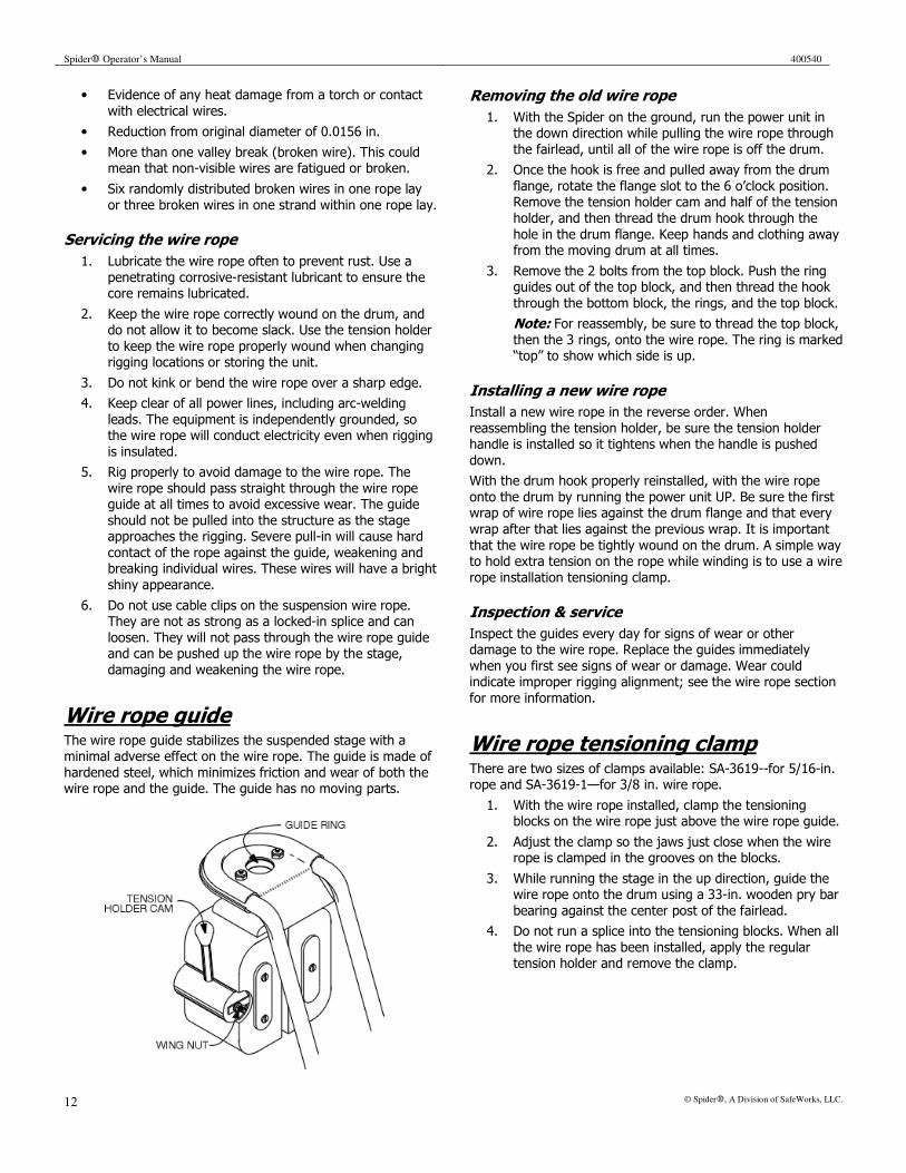
Wire rope guide The wire rope guide stabilizes the suspended stage with a minimal adverse effect on the wire rope. The guide is made of
hardened steel, which minimizes friction and wear of both the wire rope and the guide. The guide has no moving parts.
Removing the old wire rope
1. With the Spider on the ground, run the power unit in the down direction while pulling the wire rope through
the fairlead, until all of the wire rope is off the drum.
2. Once the hook is free and pulled away from the drum
flange, rotate the flange slot to the 6 o’clock position. Remove the tension holder cam and half of the tension
holder, and then thread the drum hook through the
hole in the drum flange. Keep hands and clothing away from the moving drum at all times.
3. Remove the 2 bolts from the top block. Push the ring guides out of the top block, and then thread the hook
through the bottom block, the rings, and the top block.
Note: For reassembly, be sure to thread the top block,
then the 3 rings, onto the wire rope. The ring is marked “top” to show which side is up.
Installing a new wire rope
Install a new wire rope in the reverse order. When
reassembling the tension holder, be sure the tension holder handle is installed so it tightens when the handle is pushed
down.
With the drum hook properly reinstalled, with the wire rope
onto the drum by running the power unit UP. Be sure the first wrap of wire rope lies against the drum flange and that every
wrap after that lies against the previous wrap. It is important
that the wire rope be tightly wound on the drum. A simple way to hold extra tension on the rope while winding is to use a wire
rope installation tensioning clamp.
Inspection & service
Inspect the guides every day for signs of wear or other damage to the wire rope. Replace the guides immediately
when you first see signs of wear or damage. Wear could indicate improper rigging alignment; see the wire rope section
for more information.
Wire rope tensioning clamp There are two sizes of clamps available: SA-3619--for 5/16-in. rope and SA-3619-1—for 3/8 in. wire rope.
1. With the wire rope installed, clamp the tensioning blocks on the wire rope just above the wire rope guide.
2. Adjust the clamp so the jaws just close when the wire rope is clamped in the grooves on the blocks.
3. While running the stage in the up direction, guide the wire rope onto the drum using a 33-in. wooden pry bar
bearing against the center post of the fairlead.
4. Do not run a splice into the tensioning blocks. When all
the wire rope has been installed, apply the regular tension holder and remove the clamp.

400540 Spider� Operator’s Manual
© Spider�, A Division of SafeWorks, LLC. 13
Caution
• Make sure the wire rope is well lubricated. It should
have no kinks and no broken or abraded wires.
• If the clamp is damaged or worn, do not repair it.
• Use the clamp only to apply tension to the wire rope as
instructed above—it has no other use.
• With IWRC wire rope, do not clamp to tight—this can
cause birdcaging.
Swaging the drum hook
The Spider drum hook can be swaged by a press with a
straight-channel die that has a ¾-in. diameter channel. A
rigging loft in your area can provide assistance.
1. Insert wire rope flush with base of hook.
2. Swage this area with a standard 3/8-in. Esco swaging die or equivalent.
3. Completely insert the hook in the die for maximum strength. Protruding swaging marks on the hook means
it is not correctly inserted. These marks will prevent the hook from entering the drum pocket.
Tension holder The tension holder is designed to keep the wire rope tight
on the drum when you must slacken the rope from the rigging. It is necessary to keep the wire rope evenly spooled
on the drum to ensure level winding.
Operating instructions
See the General operating instructions on page 7.
Inspection
Visually inspect the rubber rollers daily. (There is no need to
disassemble the tension holder, but definite signs of wear require a more thorough inspection.)
At the first sign of wear and at least every 30 days, remove the wing nut from the locking cam and remove the pin and
cam from the assembly. (For reassembly, note how the two
steel straps extend through the roller assembly.) Pull the roller assembly away. Examine the four rollers for deep
grooves or flat spots. Spin each roller to make sure the bearings are free and properly lubricated.
If no further service is required, reassemble the roller. Install the cam so the roller tightens on the wire rope when
the handle is pushed down.
Note: On the ST-26 the handle needs to go up so it won’t interfere with the cross tube on the quadrapod.
Service
If the bearings need lubrication, remove the 4 bearing shields (located on each side of the roller assemblies.) Pack
the bearings with bearing grease and replace the shields. If replacing either the bearings or the rollers, remove the
remaining half of the roller assembly as follows:
1. Remove the front hanger clip by rotating the tension holder body clockwise. At the same time, index the
open side away from the front as far as possible while pulling down on the back hanger strap. Pull
the hook end of the front hanger strap out of the front hole on the underneath side of the bottom
plate.
Spider� Operator’s Manual 400540
14 © Spider�, A Division of SafeWorks, LLC.
2. Remove the tension holder counterclockwise from
vertical to horizontal and index it so the open side of the tension holder is now facing away or toward the
back of the staging. Pull the clip out of the hole.
3. With the bearing shields removed, remove the
setscrew from the bearing and hold the roller from turning while loosening the socket head screw
located in the bearing. The replacement parts are available from your Spider representative.
Reverse these steps to reassemble the tension holder. When the roller is replaced in the housing, be sure to center the two
steel washers on each side of the roller around the centerline of the roller. The bearings are inserted through the housing
and seated into the washers. The screw passes through the one bearing, the washers and roller and then screws into the
opposite bearing. Be sure to pack the bearings with grease before assembling the bearing shields.
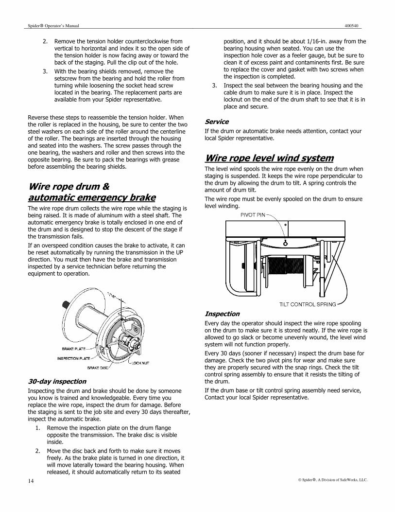
Wire rope drum & automatic emergency brake The wire rope drum collects the wire rope while the staging is being raised. It is made of aluminum with a steel shaft. The
automatic emergency brake is totally enclosed in one end of the drum and is designed to stop the descent of the stage if
the transmission fails.
If an overspeed condition causes the brake to activate, it can be reset automatically by running the transmission in the UP
direction. You must then have the brake and transmission inspected by a service technician before returning the
equipment to operation.
30-day inspection
Inspecting the drum and brake should be done by someone you know is trained and knowledgeable. Every time you
replace the wire rope, inspect the drum for damage. Before the staging is sent to the job site and every 30 days thereafter,
inspect the automatic brake.
1. Remove the inspection plate on the drum flange
opposite the transmission. The brake disc is visible inside.
2. Move the disc back and forth to make sure it moves freely. As the brake plate is turned in one direction, it
will move laterally toward the bearing housing. When released, it should automatically return to its seated
position, and it should be about 1/16-in. away from the
bearing housing when seated. You can use the inspection hole cover as a feeler gauge, but be sure to
clean it of excess paint and contaminents first. Be sure to replace the cover and gasket with two screws when
the inspection is completed.
3. Inspect the seal between the bearing housing and the
cable drum to make sure it is in place. Inspect the locknut on the end of the drum shaft to see that it is in
place and secure.
Service
If the drum or automatic brake needs attention, contact your
local Spider representative.
Wire rope level wind system The level wind spools the wire rope evenly on the drum when
staging is suspended. It keeps the wire rope perpendicular to
the drum by allowing the drum to tilt. A spring controls the amount of drum tilt.
The wire rope must be evenly spooled on the drum to ensure level winding.
Inspection
Every day the operator should inspect the wire rope spooling
on the drum to make sure it is stored neatly. If the wire rope is allowed to go slack or become unevenly wound, the level wind
system will not function properly.
Every 30 days (sooner if necessary) inspect the drum base for
damage. Check the two pivot pins for wear and make sure they are properly secured with the snap rings. Check the tilt
control spring assembly to ensure that it resists the tilting of the drum.
If the drum base or tilt control spring assembly need service, Contact your local Spider representative.

400540 Spider� Operator’s Manual
© Spider�, A Division of SafeWorks, LLC. 15
Transmission
Both the air and electric units have a worm gear transmission.
Inspection
Every 30 days (sooner if there are oil leaks) inspect the oil
level in both sections of the transmission through the inspection hole. If the level is below the hole, fill with Mobil
SHC 634 cylinder oil. Use no substitutes. At the same time inspect the bronze gear. The width of a new gear tooth is
approximately 1/16-in. If the edge of the tooth is getting sharp, replace the gears. Contact your local Spider
representative.
1. On electric models, lay the stage down on the fairlead
side and remove the drain plug. Look at the outer edge of the gear teeth. The sharper the edge, the thinner
the tooth. (For an easy check, put the worn gear next to a new one.)
2. On air models, inspect the bronze gear from the filler hole. Tip the stage to keep oil from draining out.
Every 12 months (sooner, if needed) drain the oil from both
sections of the transmission and replace with new Mobil SHC 634 cylinder oil. Use no substitutes. One quart will fill both
sections of all hoists except the ST-26, which needs about 2 quarts.
Overload switch The overload shut-off switch limits the amount of load that can
be applied to the wire rope. This keeps a safety factor on the wire rope and rigging and prevents overworking the hoist
motor.
Inspection
Every 30 days, or before installation on a new job, the overload shut-off switch should be inspected for proper
operation by someone you or the employer knows is trained and knowledgeable:
1. With all the wire rope stored neatly on the drum and the free end rigged to a beam of adequate strength,
load the staging with the rated working load as shown on the load rating plate.
2. When connected to a proper voltage or air supply, the staging should lift the load.
3. With the addition of another 100 lbs, the overload shut-
off switch should prevent the upward travel of the stage.
Testing the overload switch using the test fixture
The overload test fixture has two strong springs—they apply a
load against the wire rope to set the overload switch.
1. With the wire rope wrapped on the drum and about 1½-
ft. of wire rope above the guide, thread the wire rope
eye through the bottom of the fixture between the
cylinders. Place the wire rope eye pin (7/8-in. x 1-in.) in the
eye and set the pin in the saddles of the fixture.
2. With the wire rope tight, hold the fixture directly above the
guide. Run the staging UP until the bottom of the fixture
is pulled down onto the guide. The cylinders will fit
over the two bolts on the
guide.
3. Turn the staging on again and let the fixture collapse
while reading the pounds of pull on the scale. For electric stages, stop the staging at 950 lbs. And jog the
load onto the scale. Otherwise, the inertia of the motor armature will affect the load setting. If the staging
continues to run past 10 on the scale, shut the control off and adjust the limit switch.
4. To adjust the overload bolt, run the staging down until tension on the wire rope is relieved. After the
adjustment has been made, run the staging slowly UP and check the load setting. Continue this until you
reach 1,000 lbs.
5. Set the lock, adjustment bolt, and jam nut,. Remove
the test fixture. Pull the splice clear of the tension holder. Set the tension holder.
When an overload condition occurs, you must remove a few hundred pounds from the stage before the overload switch will
re-engage and allow the stage to move up. You might need to
return the stage to ground level or suspend it with a transfer chain.
Service
1. If the shut-off actuates at too light a load, adjust the
overload bolt (up for the electric unit and down for the air unit). The opposite is true for too heavy a load. To
adjust the bolt on an electric stage, hold the actuating system with a wrench. Loosen the jam nut with another
wrench. On an air hoist, the jam nut can be loosened with one wrench.
2. Index the adjustment bolt one turn at a time until the proper setting is reached.
3. Reset the jam nut.
4. If the overload assembly needs further assistance,
contact your local Spider representative.

Spider� Operator’s Manual 400540
16 © Spider�, A Division of SafeWorks, LLC.
Motor control switch Move the motor control handle UP or DOWN to move the
stage. Stop the stage by returning the handle to STOP.
The electric stage is con-trolled by a positive-centering rotary drum reversing switch.
The handle is set in a slot in the control housing to prevent
the operator from changing direction without giving the
motor enough time to stop. This can damage the motor
and impair motor control.
The air stage has a 4-way positive-centering Versa valve with one stop position in the center. The valve is sealed to help prevent contamination.
Inspection & service
The operator should test the control switch in both directions before each work shift. Any unusual behavior in operation
requires a further inspection by a person you or the employer knows is trained and knowledgeable. Every 30 days, or before
being sent out to a new job, the motor control switch should be inspected.
1. With the proper power supply connected to the stage, operate the switch in both directions and make sure the
drum turns in the correct direction. Be sure to keep the wire rope from going slack on the drum when doing
this.
2. Examine the handle and control assembly to make sure
it is secured and not damaged in a way that would prevent its correct use.
If the control assembly needs further service, contact your local Spider representative.
Electric hoist The motor on the electric hoist is a capacitor start/run motor
requiring either 115 or 230 volts AC., single phase, depending on the model designation. If the motor fails to run, refer to the
troubleshooting section of this booklet. The motor, stage, and all brakes should be inspected daily during the operation of the
hoist for any unusual conditions or noise that might prompt
further inspection.
Primary brake
The primary brake on the electric hoist automatically activates when the control switch is turned OFF. The brake stops motor
rotation and prevents drifting when the control switch is OFF.
Solenoid brake inspection
Check daily for any unusual conditions that might occur during operation. If the unit is making a buzzing sound or if the stage
requires 2-in. or more of travel before stopping, further inspection is necessary. Do not continue to use the stage if an
unusual condition exists. Every 30 days, a person you or your
employer knows to be trained and knowledgeable should inspect the stage and brake.
1. Disconnect the supply cord then remove the brake cover.
2. Examine the brake lining for wear. The lining is approximately 3/16-in. thick when new.
3. Push the solenoid plunger down. The brake shoes should just release the drum. Keep the plunger and
frame seating surfaces and the air gap clean—dirty surfaces cause solenoid noise and possible failure. The
plunger gap should be ½-in.
4. Replace the cover and connect the supply cord.
5. Operate the switch and listen for the click of the solenoid. If a distinct buzzing sound comes from the
solenoid when energized, the plunger is not seating properly and could cause the solenoid to burn out.
6. If the primary brake assembly need repair, contact your local Spider representative.
Electromagnetic brake inspection
The operator must be aware of any unusual conditions that might occur during the operation of the stage

400540 Spider� Operator’s Manual
© Spider�, A Division of SafeWorks, LLC. 17
Electric power supply
The available power supply (115 or 230 volts single-phase at the control assembly plug) must be maintained when the
staging is lifting its maximum intended load. The model
designation plate indicates the required voltage. The power supply locking plug on the control assembly will also indicate
the required voltage. If running the stage from a motor generator, use a minimum of 2,500 watts per stage. Do not
use demand governor. If a transformer is used, use no less than 1.5 KVA. Be certain that the output voltage is correct and
properly fused.
Inspection
The operator can tell if the stage is not getting enough power. If the motor pulsates or makes unusual noises while operating,
further inspection by a trained and knowledgeable person is needed. Every 30 days or during installation, a trained and
knowledgeable person should inspect the stage and power supply.
1. Examine the plugs on the stage and supply cord to
make sure that they are correct NEMA standard for the voltage being supplied. The plugs should be the correct
voltage and be rated at 20 amps for G.E. and 15 amps for DYNA motors.
2. Examine the plugs and rubber boots for any signs of damage that might prevent correct use.
3. Use as short a supply cord as necessary. Use wire no smaller than 10 gauge.
4. Always connect the supply cord to a good source of voltage and make sure it is protected by a 20-amp fuse
or circuit breaker. Make sure that no other machines are drawing from the same supply. This may cause a
motor to burn out due to voltage fluctuations.
5. Check voltage and current at the control while the
motor is running and lifting its maximum intended load. Voltage should not vary from the rated voltage by more
than 10%--a 10% reduction in voltage results in a 20% loss of power. Large voltage fluctuations can cause the
motor to burn out. Keep wire rope length at a minimum
if a low voltage condition exists that cannot be easily remedied.
Troubleshooting the electric hoist
Unit will not run up or down
Power supply not adequate.
Check the supply cord for breaks or faulty connection. The cord should be no smaller than 10 gauge. Voltage should be within 10% of nameplate rating with the motor running under load.
Motor burned out; short or open circuit.
1. Check the outside cover of motor for discoloration or signs of heat. With the switch in the UP or DOWN position and the supply cord disconnected, there should be about 1 ohm resistance between the two power leads of the plug.
2. If zero or infinite resistance, check the motor itself.
3. If the reading is the same when the motor is disconnected and tested, the motor is probably burned out.
4. If the motor reads 1 ohm of resistance between wires #2, 4, 10 and #1, 3, and 5, the problem may be in the switch.
Capacitor weak or burned out.
Check for oil leaking from capacitor; change capacitor.
Unit runs up but not down
Overload switch activated.
Check unit for overload condition. Check the switch for incorrect adjustment.
Reversing switch. Check for disconnected wire or signs that a contact is burned.
Power supply not adequate.
Check amperes and voltage at the reversing switch plug. They should be within 10%. If not, a transformer or other corrective measure needs to be made.
Power cord is too long.
Check length; shorten if possible.

Spider� Operator’s Manual 400540
18 © Spider�, A Division of SafeWorks, LLC.
Air hoist Motor
The air motor is a totally enclosed vane type motor rated at 1 hp, with 120 psi and 60 cfm air. The air hose supply line needs
to be at least ¾-in. I.D. in order to get maximum horsepower.
Inspection & service
Daily, the operator should refer any unusual behavior (such as loss of power) to a trained or knowledgeable person for further
inspection. See Troubleshooting.
Every 30 days, or before installation at a new job site, the
motor should be inspected by a trained and knowledgeable
person.
1. The cover fasteners must be secure, but do not over
tighten.
2. Inspect the housing for any signs of damage.
3. Make sure the air hoses are properly secured and not damaged.
If the air motor needs further repair, contact your local Spider representative.
Oiler & filter
The filter helps to remove dirt and water from the incoming air
supply. The oiler supplies a metered amount of lubricant for the motor.
CAUTION These units are intended for use in industrial compressed air systems only, they must not be used where pressure or tem-perature may exceed maximum rated operation conditions.
Inspection &service
Disconnect air supply before proceeding.
Drain the filter at least once a day and more frequently if necessary. To drain, loosen the thumbscrew located on the
bottom of the filter. After the water has drained, reset the
thumbscrew. Inspect the oiler daily. Remove filler cap on top of the oiler assembly. Fill with Mobil Almo Oil No. 525.
Every 30 days (sooner if needed) remove and clean the filter screen. When operating under extreme conditions such as
sandblasting, clean the filter daily.
Norgren 12-02 and 10-02 filter and oiler. Release the clip at the top of the filter bowl and remove. Loosen the baffle at the bottom of the screen. Remove the screen and clean it in
thinner or solvent. Blow the filter dry and replace. Do not over tighten the baffle.
Set oil drip rate at 3-4 drops/minute. To adjust the flow rate, connect to air supply and run motor at full throttle in UP
direction. Remove wire and plastic cap from the top of the oiler. The adjusting screw is located under the cap. With a
screwdriver, turn the screw counterclockwise to increase the drip rate, clockwise to decrease. Purge the air hose of any
contamination before using.
Norgren series F-12 and L-12 filter and oiler Norgren series F-74 and L-74 filter and oiler Remove the filter bowl (unscrew the F-12 bowl, or twist and remove the F-74 bowl). Remove the baffle at the bottom of
the filter assembly, and then pull out the filter element and o-
ring. Clean the parts with warm water and soap. Blow air through the filter element in direction opposite that of normal
airflow to dislodge surface contaminants. Dry all parts and blow out internal passages in body using clean dry compressed
air. Replace any damaged parts.
At reassembly, apply a coat of Dow Corning 44M grease (or equivalent) to the o-rings. Replace the o-ring, louver and filter
element as they were removed and torque the baffle finger tight. Apply an even amount of anti-seize compound (Armite
Laboratories Led-Plate No. 250 or equivalent) to the threads of the filter bowl before installing.
The oiler adjustment screw is located under the cap on the top of the assembly. Turn counterclockwise to increase the drip
rate and clockwise to decrease. Adjust while running motor at
full throttle in UP direction. Set oil drip rate at 3-4 drops per minute.
Frame
The frame is constructed of high strength aluminum
alloys with heliarc-welded joints.
CAUTION The frame is constructed from tempered metal. Do not use heat to clean off excess paint. If welding repairs are needed, they must be made by welders certified to AWS standards,
and in compliance with AWS structural welding code D1.2-97 (or current revision). Contact your local Spider representative.
Inspection &service
Daily, the operator should check for and report any damage. The safety information in the beginning of this manual and
posted on the Spider equipment lists some of the ways the equipment can be damaged.
Every 30 days, or before installing on a new job, inspect the frame thoroughly for damage. Wire brush or scrub the excess
paint away from suspected joints and inspect for cracks. For a unit equipped with floor mats, the mats can be removed and
cleaned off or replaced.

400540 Spider� Operator’s Manual
© Spider�, A Division of SafeWorks, LLC. 19
Troubleshooting the air hoist
Motor is running slowly, losing power
Low air volume. Check air supply at hoist—there should be 90 psi with motor running and control valve wide open. Lower psi indicates need for larger compressor or larger hose/fittings.
Not enough oil or too much oil.
Check lubricator—make sure it’s clean, full of oil, and correctly adjusted (3-4 drops/minute).
Plugged air filter. Disassemble and clean.
Swollen vanes, badly worn vanes or worn front rotor bearing.
Return for service.
Motor is sluggish in down direction
Too much oil. Is lubricator correctly adjusted? Run motor in down direction until it has discharged excess oil and is running normally.
Motor will not move in either direction
Disassembly shows no visible wear or scoring on any parts.
Swollen vanes. Return for service.
Storing & transporting
Always store and transport your Spider equipment in the upright position. This will help prevent water accumulation in
the electrical system and avoid the possibility of oil leakage in the transmission.
Always store your equipment in a sheltered dry area. If the equipment is left out in the weather, be sure to inspect the
wire rope and other components for rust and corrosion. After long periods of storage under any conditions, the equipment
should be thoroughly inspected before use.
Every 30 days connect the staging to a proper power supply
and run at least a couple of revolutions to lubricate the gears.
Notes

Spider� Operator’s Manual 400540
20 © Spider�, A Division of SafeWorks, LLC.
Accessory equipment
Safety equipment Read the pages at the beginning of the manual. An inde-pendant safety line must be used by each person working on
the scaffold. Each person must wear an approved safety harness equipped with a lanyard connected to a rope grab
device. Full body harness is recommended because of its
ability to withstand greater shock without injury.
Independent safety line
If the scaffold has a fixed roof or if using multi-level scaffolds, an independent safety line must be attached to the scaffold
hoist units. Each person should wear a safety harness with a lanyard connected to a trolley line. Secure trolley line to the
chain guard at each work basket.
1. Rig a 5/16-in. wire rope the length of the complete
travel of the scaffold at the same place as the suspension line. Do not rig to the same rigging as the
suspension line.
2. Attach the Secondary Safety Line Bracket Assembly
(008478-1) to the transfer chain area (the steel guard bracket below the top wire rope guide assembly) of the
Spider hoist unit per the instructions provided with the assembly.
Harness
• Inspect the harness material. Hold the belt in an
inverted “U” with the body side toward the body and
hands 6-in. apart. Inspect the entire length, looking for frayed edges, broken fibers, pulled stitches, cuts, or
chemical damage. Broken strands appear as tufts on the webbing surface. Broken, cut or burned stitches are
easily seen.
• Inspect buckles and D-rings. Make sure both are firmly attached to the belt. Rivets should be tight and rigid
and bases and burrs should be flat against the material. Bent rivets will fail under stress. Inspect condition of D-
ring rivets and metal wear pads. Discolored, split, or
cracked rivets indicate chemical corrosion. Buckle tongues should be undamaged, overlap the buckle
frame, and move freely back and forth. The roller
should turn freely on the frame. Look for sharp edges.
On friction buckles, make sure outer and center bars are straight. Pay particular attention to corners and
attachment points of the center bar. On sliding bar buckles, inspect the frame and sliding bar for cracks,
distortion, or sharp edges. The bar should slide freely. Pay special attention to the corners and ends of the
sliding bar.
• Check belt ends to make sure grommets are still in
place. Belts with grommet-less holes should be checked
for torn or elongated holes.
Inspection
Carefully inspect each harness each time it is used. At least
once every 3 months, a trained inspector should examine harness. Maintain harness according to manufacturer’s
instructions.
Lifeline
Examine the surface of manila rope for cuts and worn or broken fibers. Discard any rope that has become smaller in
diameter or has a broken look. Inspect inner fibers of the rope for breaks, discoloration, and deterioration; discard if it shows
any of these signs.
Examine the wire rope for broken strands, rust, and kinks that
may weaken it. Ropes must be kept clean, dry, and rust-free. They should be lubricated frequently, especially before use in
acid atmospheres or before exposure to salt water. After such use, it should be carefully cleaned and coated with oil.
Polypropylene rope can be weakened by heat, continued
exposure to direct sunlight, and broken cuts or strands. Examine the cover yarn frequently for signs of damage or
deterioration.
Inspection
Carefully inspect lines each time they are used. Inspect and maintain according to manufacturer’s instructions.
Rope grabs
Clean rope grabs before each use. Do not allow them to
become dirty or sticky during use. Inspect before each use to make sure there are no worn, bent, or weakened parts.
Replace and discard worn parts immediately, Inspect and
maintain rope grabs according to manufacturer’s instructions.
400540 Spider� Operator’s Manual
© Spider�, A Division of SafeWorks, LLC. 21
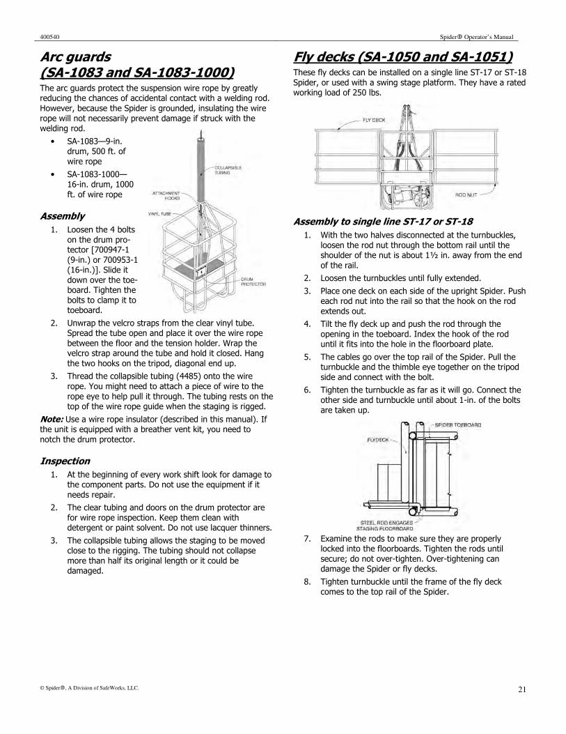
Arc guards (SA-1083 and SA-1083-1000) The arc guards protect the suspension wire rope by greatly reducing the chances of accidental contact with a welding rod.
However, because the Spider is grounded, insulating the wire
rope will not necessarily prevent damage if struck with the welding rod.
• SA-1083—9-in. drum, 500 ft. of
wire rope
• SA-1083-1000— 16-in. drum, 1000
ft. of wire rope
Assembly
1. Loosen the 4 bolts
on the drum pro-tector [700947-1
(9-in.) or 700953-1 (16-in.)]. Slide it
down over the toe-board. Tighten the
bolts to clamp it to toeboard.
2. Unwrap the velcro straps from the clear vinyl tube. Spread the tube open and place it over the wire rope
between the floor and the tension holder. Wrap the velcro strap around the tube and hold it closed. Hang
the two hooks on the tripod, diagonal end up.
3. Thread the collapsible tubing (4485) onto the wire
rope. You might need to attach a piece of wire to the
rope eye to help pull it through. The tubing rests on the top of the wire rope guide when the staging is rigged.
Note: Use a wire rope insulator (described in this manual). If the unit is equipped with a breather vent kit, you need to
notch the drum protector.
Inspection
1. At the beginning of every work shift look for damage to the component parts. Do not use the equipment if it
needs repair.
2. The clear tubing and doors on the drum protector are
for wire rope inspection. Keep them clean with detergent or paint solvent. Do not use lacquer thinners.
3. The collapsible tubing allows the staging to be moved close to the rigging. The tubing should not collapse
more than half its original length or it could be damaged.
Fly decks (SA-1050 and SA-1051) These fly decks can be installed on a single line ST-17 or ST-18
Spider, or used with a swing stage platform. They have a rated working load of 250 lbs.
Assembly to single line ST-17 or ST-18
1. With the two halves disconnected at the turnbuckles,
loosen the rod nut through the bottom rail until the shoulder of the nut is about 1½ in. away from the end
of the rail.
2. Loosen the turnbuckles until fully extended.
3. Place one deck on each side of the upright Spider. Push each rod nut into the rail so that the hook on the rod
extends out.
4. Tilt the fly deck up and push the rod through the
opening in the toeboard. Index the hook of the rod until it fits into the hole in the floorboard plate.
5. The cables go over the top rail of the Spider. Pull the turnbuckle and the thimble eye together on the tripod
side and connect with the bolt.
6. Tighten the turnbuckle as far as it will go. Connect the
other side and turnbuckle until about 1-in. of the bolts are taken up.
7. Examine the rods to make sure they are properly locked into the floorboards. Tighten the rods until
secure; do not over-tighten. Over-tightening can damage the Spider or fly decks.
8. Tighten turnbuckle until the frame of the fly deck comes to the top rail of the Spider.
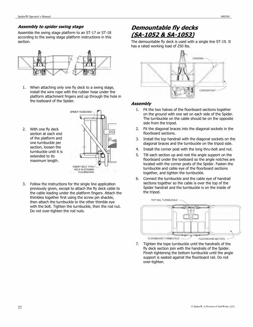
Spider� Operator’s Manual 400540
22 © Spider�, A Division of SafeWorks, LLC.
Assembly to spider swing stage
Assemble the swing stage platform to an ST-17 or ST-18 according to the swing stage platform instructions in this
section.
1. When attaching only one fly deck to a swing stage,
install the wire rope with the rubber hose under the platform attachment fingers and up through the hole in
the toeboard of the Spider.
2. With one fly deck
section at each end of the platform and
one turnbuckle per section, loosen the
turnbuckle until it is extended to its
maximum length.
3. Follow the instructions for the single line application previously given, except to attach the fly deck cable to
the cable leading under the platform fingers. Attach the thimbles together first using the screw pin shackle,
then attach the turnbuckle to the other thimble eye with the bolt. Tighten the turnbuckle, then the rod nut.
Do not over-tighten the rod nuts.
Demountable fly decks (SA-1052 & SA-1053) The demountable fly deck is used with a single line ST-19. It has a rated working load of 250 lbs.
Assembly
1. Fit the two halves of the floorboard sections together
on the ground with one set on each side of the Spider. The turnbuckle on the cable should be on the opposite
side from the tripod.
2. Fit the diagonal braces into the diagonal sockets in the
floorboard sections.
3. Install the top handrail with the diagonal sockets on the
diagonal braces and the turnbuckle on the tripod side.
4. Install the corner post with the long thru-bolt and nut.
5. Tilt each section up and rest the angle support on the
floorboard under the toeboard so the angle notches are located with the corner posts of the Spider. Fasten the
turnbuckle and cable eye of the floorboard sections together, and tighten the turnbuckle.
6. Connect the turnbuckle and the cable eye of handrail sections together so the cable is over the top of the
Spider handrail and the turnbuckle is on the inside of the tripod.
7. Tighten the tope turnbuckle until the handrails of the
fly deck section join with the handrails of the Spider. Finish tightening the bottom turnbuckle until the angle
support is seated against the floorboard rail. Do not over-tighten.
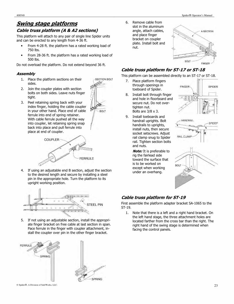
400540 Spider� Operator’s Manual
© Spider�, A Division of SafeWorks, LLC. 23
Swing stage platforms Cable truss platform (A & A2 sections)
This platform will attach to any pair of single line Spider units and can be erected to any length from 4-36 ft.
• From 4-28 ft. the platform has a rated working load of
750 lbs.
• From 28-36 ft. the platform has a rated working load of
500 lbs.
Do not overload the platform. Do not extend beyond 36 ft.
Assembly
1. Place the platform sections on their sides.
2. Join the coupler plates with section bolts on both sides. Leave nuts finger
tight.
3. Peel retaining spring back with your
index finger, holding the cable coupler in your other hand. Place end of cable
ferrule into end of spring retainer.
With cable ferrule pushed all the way into coupler, let retaining spring snap
back into place and pull ferrule into place at end of coupler.
4. If using an adjustable end B section, adjust the section to the desired length and secure by installing a steel
pin in the appropriate hole. Turn the platform to its upright working position.
5. If not using an adjustable section, install the appropri-
ate finger bracket on free cable at last section in span. Pace ferrule in the finger with coupler attachment, in-
stall the coupler over pin in the other finger bracket.
6. Remove cable from
slot in the aluminum angle, attach cables,
and place finger bracket on coupler
plate. Install bolt and nut.
Cable truss platform for ST-17 or ST-18
This platform can be assembled directly to an ST-17 or ST-18.
7. Place platform fingers
through openings in toeboard of Spider.
8. Install bolt through finger and hole in floorboard and
secure nut. Do not over-tighten nut.
Bolts are 3/8 x 3.
9. Install toeboards and handrail uprights. Bolt
handrails to uprights, install nuts, then secure
socket setscrews. Adjust rail clamp snug to Spider
rail. Tighten section bolts and nuts.
Note: It is preferable to rig the fairlead side
toward the surface that is to be worked on
except when working under an overhang.
Cable truss platform for ST-19
First assemble the platform adapter bracket SA-1065 to the
ST-19.
1. Note that there is a left and a right hand bracket. On
the left hand stage, the three attachment holes are located farther from the cross bar than the right. The
right hand of the swing stage is determined when facing the control panels.
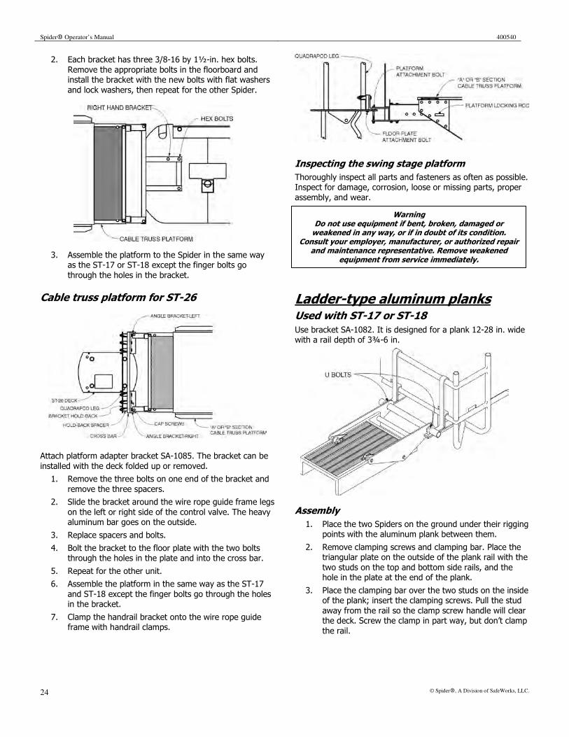
Spider� Operator’s Manual 400540
24 © Spider�, A Division of SafeWorks, LLC.
2. Each bracket has three 3/8-16 by 1½-in. hex bolts.
Remove the appropriate bolts in the floorboard and install the bracket with the new bolts with flat washers
and lock washers, then repeat for the other Spider.
3. Assemble the platform to the Spider in the same way as the ST-17 or ST-18 except the finger bolts go
through the holes in the bracket.
Cable truss platform for ST-26
Attach platform adapter bracket SA-1085. The bracket can be
installed with the deck folded up or removed.
1. Remove the three bolts on one end of the bracket and
remove the three spacers.
2. Slide the bracket around the wire rope guide frame legs
on the left or right side of the control valve. The heavy aluminum bar goes on the outside.
3. Replace spacers and bolts.
4. Bolt the bracket to the floor plate with the two bolts through the holes in the plate and into the cross bar.
5. Repeat for the other unit.
6. Assemble the platform in the same way as the ST-17
and ST-18 except the finger bolts go through the holes in the bracket.
7. Clamp the handrail bracket onto the wire rope guide frame with handrail clamps.
Inspecting the swing stage platform
Thoroughly inspect all parts and fasteners as often as possible. Inspect for damage, corrosion, loose or missing parts, proper
assembly, and wear.
Ladder-type aluminum planks Used with ST-17 or ST-18
Use bracket SA-1082. It is designed for a plank 12-28 in. wide with a rail depth of 3¾-6 in.
Assembly
1. Place the two Spiders on the ground under their rigging points with the aluminum plank between them.
2. Remove clamping screws and clamping bar. Place the triangular plate on the outside of the plank rail with the
two studs on the top and bottom side rails, and the hole in the plate at the end of the plank.
3. Place the clamping bar over the two studs on the inside of the plank; insert the clamping screws. Pull the stud
away from the rail so the clamp screw handle will clear the deck. Screw the clamp in part way, but don’t clamp
the rail.
Warning Do not use equipment if bent, broken, damaged or weakened in any way, or if in doubt of its condition.
Consult your employer, manufacturer, or authorized repair and maintenance representative. Remove weakened
equipment from service immediately.
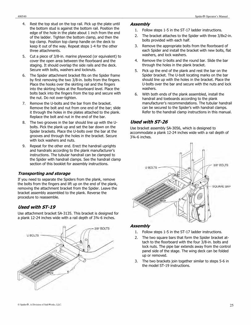
400540 Spider� Operator’s Manual
© Spider�, A Division of SafeWorks, LLC. 25
4. Rest the top stud on the top rail. Pick up the plate until
the bottom stud is against the bottom rail. Position the edge of the hole in the plate about 1 inch from the end
of the ladder. Tighten the bottom clamp, and then the top clamp. Position top clamp handle on the deck to
keep it out of the way. Repeat steps 1-4 for the other three attachments.
5. Cut a piece of 3/8-in. marine plywood (or equivalent) to
cover the open area between the floorboard and the staging. It should overlap the side rails and the deck.
Secure with bolts, washers and locknuts.
6. The Spider attachment bracket fits on the Spider frame
by first removing the two 3/8-in. bolts from the fingers. Place the hooks over the skirting rail and the fingers
into the skirting holes at the floorboard level. Place the bolts back into the fingers from the top and secure with
the nut. Do not over-tighten.
7. Remove the U-bolts and the bar from the bracket.
Remove the bolt and nut from one end of the bar; slide it through the holes in the plates attached to the plank.
Replace the bolt and nut in the end of the bar.
8. The two grooves in the bar should line up with the U-
bolts. Pick the plank up and set the bar down on the Spider brackets. Place the U-bolts over the bar at the
grooves and through the holes in the bracket. Secure
with lock washers and nuts.
9. Repeat for the other end. Erect the handrail uprights
and handrails according to the plank manufacturer’s instructions. The tubular handrail can be clamped to
the Spider with handrail clamps. See the handrail clamp section of this booklet for assembly instructions.
Transporting and storage
If you need to separate the Spiders from the plank, remove
the bolts from the fingers and lift up on the end of the plank, removing the attachment bracket from the Spider. Leave the
bracket assembly assembled to the plank. Reverse the procedure to reassemble.
Used with ST-19
Use attachment bracket SA-3135. This bracket is designed for a plank 12-24 inches wide with a rail depth of 3¾-6 inches.
Assembly
1. Follow steps 1-5 in the ST-17 ladder instructions.
2. The bracket attaches to the Spider with three 3/8x2-in.
bolts provided with each half.
3. Remove the appropriate bolts from the floorboard of
each Spider and install the bracket with new bolts, flat
washers, and lock washers.
4. Remove the U-bolts and the round bar. Slide the bar
through the holes in the plank bracket.
5. Pick up the end of the plank and rest the bar on the
Spider bracket. The U-bolt locating marks on the bar should line up with the holes in the bracket. Place the
U-bolts over the bar and secure with the nuts and lock washers.
6. With both ends of the plank assembled, install the handrail and toeboards according to the plank
manufacturer’s recommendations. The tubular handrail can be secured to the Spider’s with handrail clamps.
Refer to the handrail clamp instructions in this manual.
Used with ST-26
Use bracket assembly SA-3056, which is designed to
accommodate a plank 12-24 inches wide with a rail depth of 3¾-6 inches.
Assembly
1. Follow steps 1-5 in the ST-17 ladder instructions.
2. The two square bars that form the Spider bracket at-
tach to the floorboard with the four 3/8-in. bolts and lock nuts. The pipe bar extends away from the control
panel side of the stage. The wing deck can be folded up or removed.
3. The two brackets join together similar to steps 5-6 in the model ST-19 instructions.
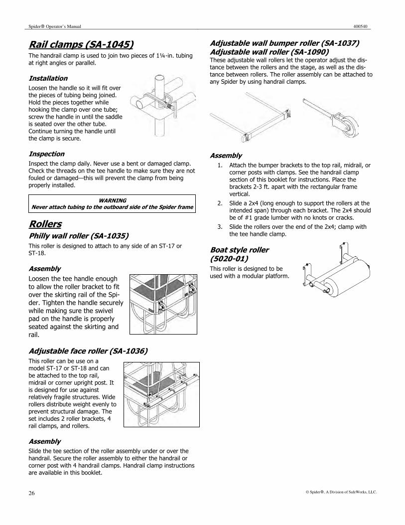
Spider� Operator’s Manual 400540
26 © Spider�, A Division of SafeWorks, LLC.
Rail clamps (SA-1045) The handrail clamp is used to join two pieces of 1¼-in. tubing
at right angles or parallel.
Installation
Loosen the handle so it will fit over the pieces of tubing being joined.
Hold the pieces together while hooking the clamp over one tube;
screw the handle in until the saddle is seated over the other tube.
Continue turning the handle until the clamp is secure.
Inspection
Inspect the clamp daily. Never use a bent or damaged clamp. Check the threads on the tee handle to make sure they are not
fouled or damaged—this will prevent the clamp from being properly installed.
Rollers Philly wall roller (SA-1035)
This roller is designed to attach to any side of an ST-17 or ST-18.
Assembly
Loosen the tee handle enough
to allow the roller bracket to fit over the skirting rail of the Spi-
der. Tighten the handle securely
while making sure the swivel pad on the handle is properly
seated against the skirting and rail.
Adjustable face roller (SA-1036)
This roller can be use on a model ST-17 or ST-18 and can
be attached to the top rail, midrail or corner upright post. It
is designed for use against relatively fragile structures. Wide
rollers distribute weight evenly to prevent structural damage. The
set includes 2 roller brackets, 4 rail clamps, and rollers.
Assembly
Slide the tee section of the roller assembly under or over the
handrail. Secure the roller assembly to either the handrail or
corner post with 4 handrail clamps. Handrail clamp instructions are available in this booklet.
Adjustable wall bumper roller (SA-1037) Adjustable wall roller (SA-1090) These adjustable wall rollers let the operator adjust the dis-tance between the rollers and the stage, as well as the dis-
tance between rollers. The roller assembly can be attached to any Spider by using handrail clamps.
Assembly
1. Attach the bumper brackets to the top rail, midrail, or corner posts with clamps. See the handrail clamp
section of this booklet for instructions. Place the brackets 2-3 ft. apart with the rectangular frame
vertical.
2. Slide a 2x4 (long enough to support the rollers at the intended span) through each bracket. The 2x4 should
be of #1 grade lumber with no knots or cracks.
3. Slide the rollers over the end of the 2x4; clamp with
the tee handle clamp.
Boat style roller (5020-01)
This roller is designed to be
used with a modular platform.
WARNING Never attach tubing to the outboard side of the Spider frame

400540 Spider� Operator’s Manual
© Spider�, A Division of SafeWorks, LLC. 27
Ground dolly (SA-1072, SA-3065) The ground dolly allows the Spider to be rolled across hard
smooth surfaces such as concrete or asphalt. To roll across a tar roof or dirt, use plywood or boards.
• SA-1072 is designed for
the ST-17, ST-18, ST-180, or ST-27.
• SA-3065 is designed for
the ST-19, but can also be used on the ST-17,
ST-18, ST-180, or ST-27.
Assembly
1. If the Spider is not suspended, lay it down on its front
or tripod side.
2. Loosen the J-bolt nuts, then attach the dolly to the
base rocker of the Spider. For the best stability, put the forward set of wheels ahead of the centerline of the
wire rope drum by about 3 inches.
Inspection
At the star of every work shift, inspect all rollers to make sure
they are not damaged or broken and that all fasteners are installed and secured. Do not use the equipment if it needs
repair. Spare parts and repair service are available from your local Spider representative.
CAUTION A loaded dolly can tip over if wheeled onto rough ground or if pushed by the upper frame. Do not ride on the stage when it is on the ground. Make sure the dolly is securely attached to the
Spider before raising it off the ground.
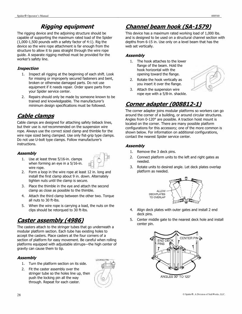
Spider� Operator’s Manual 400540
28 © Spider�, A Division of SafeWorks, LLC.
Rigging equipment The rigging device and the adjoining structure should be
capable of supporting the maximum rated load of the Spider (1,000-1,500 pounds with a safety factor of 4:1). Rig the
device so the wire rope attachment is far enough from the structure to allow it to pass straight through the wire rope
guide. A separate rigging method must be provided for the worker’s safety line.
Inspection
1. Inspect all rigging at the beginning of each shift. Look
for missing or improperly secured fasteners and bent, broken or otherwise damaged parts. Do not use
equipment if it needs repair. Order spare parts from your Spider service center.
2. Repairs should only be made by someone known to be trained and knowledgeable. The manufacturer’s
minimum design specifications must be followed.
Cable clamps Cable clamps are designed for attaching safety tieback lines,
but their use is not recommended on the suspension wire rope. Always use the correct sized clamp and thimble for the
wire rope sized being clamped. Use only fist-grip type clamps. Do not use U-bolt type clamps. Follow manufacturer’s
instructions.
Assembly
1. Use at least three 5/16-in. clamps
when forming an eye in a 5/16-in. wire rope.
2. Form a loop in the wire rope at least 12 in. long and install the first clamp about 9 in. down. Alternately
tighten nuts until the clamp is secure.
3. Place the thimble in the eye and attach the second
clamp as close as possible to the thimble.
4. Attach the third clamp between the other two. Torque
all nuts to 30 ft-lbs.
5. When the wire rope is carrying a load, the nuts on the
clips should be retorqued to 30 ft-lbs.
Caster assembly (4986) The casters attach to the stringer tubes that go underneath a
modular platform section. Each tube has existing holes to accept the casters. Place casters at the four corners of a
section of platform for easy movement. Be careful when rolling platforms equipped with adjustable stirrups—the high center of
gravity can cause them to tip.
Assembly
1. Turn the platform section on its side.
2. Fit the caster assembly over the stringer tube so the holes line up, then
push the locking pin all the way through. Repeat for each caster.
Channel beam hook (SA-1579) This device has a maximum rated working load of 1,000 lbs.
and is designed to be used on a structural channel section with depths from 6-15 in. Use only on a level beam that has the
web set vertically.
Assembly
1. The hook attaches to the lower flange of the beam. Hold the
hook horizontal with the opening toward the flange.
2. Rotate the hook vertically as you insert it over the flange.
3. Attach the suspension wire rope eye with a 5/8-in. shackle.
Corner adapter (008812-1) The corner adapter joins modular platforms so workers can go around the corner of a building, or around circular structures.
Angles from 0-120° are possible. A traction hoist mount is located on the corner. There are many possible platform
configurations for this accessory; one of the more common is shown below. For information on additional configurations,
contact the nearest Spider service center.
Assembly
1. Remove the 3 deck pins.
2. Connect platform units to the left and right gates as needed.
3. Rotate units to desired angle. Let deck plates overlap platform as needed.
4. Align deck plates with outer gates and install 2 end deck pins.
5. Center middle gate to the nearest deck hole and install center pin.

400540 Spider� Operator’s Manual
© Spider�, A Division of SafeWorks, LLC. 29
6. Raise handrail chains to correct height and adjust to
keep them taut.
End adapter stirrup (4971) This adapter is used at the ends of a modular platform to attach either a Spider basket or a traction hoist. The illus-
trations show the stirrup adapter, and the adapter joining a Spider with a platform.
Assembly
1. Lift the end of the modular platform. Position the lower pins of the platform into the pockets of the end
adapter.
2. Insert the upper locking pins and secure them with the
retaining clips.
3. For a Spider basket: remove the two 3/8-16 UNC x 3¾
bolts from the finger assemblies of the end adapter. Lift the end of the platform and position the fingers
through the openings in the toeboard of the basket. Install the bolts through the fingers and holes in the
floorboards; secure with locknuts. Do not over-tighten.
4. For a traction hoist: insert the stirrup frame of the
traction hoist into the hoist mounts. Secure with ½-13 UNC bolts and locknuts. The bolts should be fully
shanked through the hoist mount.
Repeat for the other end of the platform.
End gate (008811-1) The end gate is typically used with the adjustable stirrup. It attaches to the end of a platform to close off the open end.
Assembly
1. Position the gate so the bottom will fit between the up-right tubes at the end of the platform. Move the gate
so the upright tube at the end of the platform is between the gate tabs. Rotate the gate to engage both
upright tubes, then swing it upright.
2. Insert locking pins and hair clips, then adjust handrail
to correct height.
Reverse procedure to remove end gate.
WARNING Do not try to change the angle of the corner adapter while suspended.
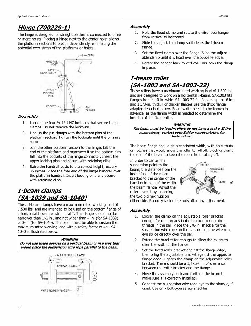
Spider� Operator’s Manual 400540
30 © Spider�, A Division of SafeWorks, LLC.
WARNING Do not use these devices on a vertical beam or in a way that would place the suspension wire rope parallel to the beam.
WARNING The beam must be level—rollers do not have a brake. If the
beam slopes, contact your Spider representative for instructions.
Hinge (700229-1) The hinge is designed for straight platforms connected to three
or more hoists. Placing a hinge next to the center hoist allows the platform sections to pivot independently, eliminating the
potential over-stress of the platforms or hoists.
Assembly
1. Loosen the four ½-13 UNC locknuts that secure the pin clamps. Do not remove the locknuts.
2. Line up the pin clamps with the bottom pins of the platform section. Tighten the locknuts until the pins are
secure.
3. Join the other platform section to the hinge. Lift the
end of the platform and maneuver it so the bottom pins fall into the pockets of the hinge connector. Insert the
upper locking pins and secure with retaining clips.
4. Raise the handrail posts to the correct height; usually
36 inches. Place the free end of the hinge handrail over the platform handrail. Insert locking pins and secure
with retaining clips.
I-beam clamps (SA-1039 and SA-1040) These I-beam clamps have a maximum rated working load of
1,500 lbs. and are intended to be used on the bottom flange of a horizontal I-beam or structural T. The flange should not be
narrower than 1½ in., and not wider than 4-in. (for SA-1039) or 8-in. (for SA-1040). The beam must be able to sustain the
maximum rated working load with a safety factor of 4:1. SA-1040 is illustrated below.
Assembly
1. Hold the fixed clamp and rotate the wire rope hanger from vertical to horizontal.
2. Slide the adjustable clamp so it clears the I-beam flange.
3. Set the fixed clamp over the flange. Slide the adjust-able clamp until it is fixed over the opposite edge.
4. Rotate the hanger back to vertical. This locks the clamp
in place.
I-beam roller (SA-1003 and SA-1003-22) These rollers have a maximum rated working load of 1,500 lbs. and are designed to work on a horizontal I-beam. SA-1003 fits
flanges from 4-10 in. wide. SA-1003-22 fits flanges up to 16 in. and 1 3/8-in. thick. For thicker flanges use the thick flange
adapter described below. Beam width needs to be known in advance, as the flange width is needed to determine the
location of the fixed roller.
The beam flange should be a consistent width, with no cutouts
or notches that would allow the roller to roll off. Block or clamp the end of the beam to keep the roller from rolling off.
In order to center the suspension point to the
beam, the distance from the inside face of the roller
bracket to the center of the bar should be half the width of
the beam flange. Adjust the roller bracket by loosening
the two big hex nuts on either side. Securely fasten the nuts after any adjustment.
Assembly
1. Loosen the clamp on the adjustable roller bracket
enough for the threads in the bracket to clear the
threads in the bar. Place the 5/8-in. shackle for the suspension wire rope on the bar, or loop the wire rope
eye splice directly over the bar.
2. Extend the bracket far enough to allow the rollers to
clear the width of the flange.
3. Set the fixed roller bracket against the flange edge,
then bring the adjustable bracket against the opposite flange edge. Tighten the clamp on the adjustable roller
bracket. There should be a 1/8-1/4 in. of clearance between the roller bracket and the flange.
4. Move the assembly back and forth on the beam to make sure it is correctly installed.
5. Connect the suspension wire rope eye to the shackle, if used. Use only bolt-type safety shackles.
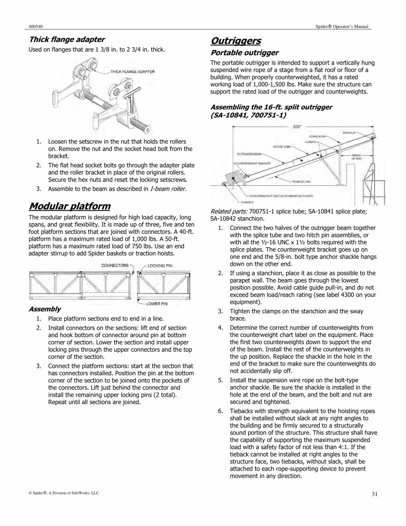
400540 Spider� Operator’s Manual
© Spider�, A Division of SafeWorks, LLC. 31
Thick flange adapter
Used on flanges that are 1 3/8 in. to 2 3/4 in. thick.
1. Loosen the setscrew in the nut that holds the rollers
on. Remove the nut and the socket head bolt from the bracket.
2. The flat head socket bolts go through the adapter plate and the roller bracket in place of the original rollers.
Secure the hex nuts and reset the locking setscrews.
3. Assemble to the beam as described in I-beam roller.
Modular platform
The modular platform is designed for high load capacity, long spans, and great flexibility. It is made up of three, five and ten
foot platform sections that are joined with connectors. A 40-ft. platform has a maximum rated load of 1,000 lbs. A 50-ft.
platform has a maximum rated load of 750 lbs. Use an end adapter stirrup to add Spider baskets or traction hoists.
Assembly
1. Place platform sections end to end in a line.
2. Install connectors on the sections: lift end of section and hook bottom of connector around pin at bottom
corner of section. Lower the section and install upper
locking pins through the upper connectors and the top corner of the section.
3. Connect the platform sections: start at the section that has connectors installed. Position the pin at the bottom
corner of the section to be joined onto the pockets of the connectors. Lift just behind the connector and
install the remaining upper locking pins (2 total). Repeat until all sections are joined.
Outriggers Portable outrigger
The portable outrigger is intended to support a vertically hung suspended wire rope of a stage from a flat roof or floor of a
building. When properly counterweighted, it has a rated working load of 1,000-1,500 lbs. Make sure the structure can
support the rated load of the outrigger and counterweights.
Assembling the 16-ft. split outrigger (SA-10841, 700751-1)
Related parts: 700751-1 splice tube; SA-10841 splice plate; SA-10842 stanchion.
1. Connect the two halves of the outrigger beam together
with the splice tube and two hitch pin assemblies, or with all the ½-16 UNC x 1½ bolts required with the
splice plates. The counterweight bracket goes up on one end and the 5/8-in. bolt type anchor shackle hangs
down on the other end.
2. If using a stanchion, place it as close as possible to the
parapet wall. The beam goes through the lowest position possible. Avoid cable guide pull-in, and do not
exceed beam load/reach rating (see label 4300 on your equipment).
3. Tighten the clamps on the stanchion and the sway brace.
4. Determine the correct number of counterweights from the counterweight chart label on the equipment. Place
the first two counterweights down to support the end of the beam. Install the rest of the counterweights in
the up position. Replace the shackle in the hole in the end of the bracket to make sure the counterweights do
not accidentally slip off.
5. Install the suspension wire rope on the bolt-type anchor shackle. Be sure the shackle is installed in the
hole at the end of the beam, and the bolt and nut are secured and tightened.
6. Tiebacks with strength equivalent to the hoisting ropes shall be installed without slack at any right angles to
the building and be firmly secured to a structurally sound portion of the structure. This structure shall have
the capability of supporting the maximum suspended load with a safety factor of not less than 4:1. If the
tieback cannot be installed at right angles to the structure face, two tiebacks, without slack, shall be
attached to each rope-supporting device to prevent movement in any direction.
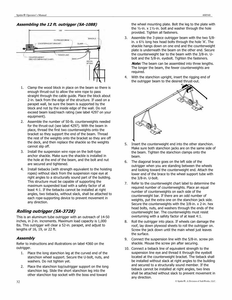
Spider� Operator’s Manual 400540
32 © Spider�, A Division of SafeWorks, LLC.
Assembling the 12 ft. outrigger (SA-1088)
1. Clamp the wood block in place on the beam so there is
enough thrust-out to allow the wire rope to pass straight through the cable guide. Place the block about
2-in. back from the edge of the structure. If used on a parapet wall, be sure the beam is supported by the
block and not by the inside edge of the wall. Do not exceed beam load/reach rating (see label 4297 on your
equipment).
2. Assemble the number of 50-lb. counterweights needed
for the thrust-out (see label 4297). With the beam in place, thread the first two counterweights onto the
bracket so they support the end of the beam. Thread
the rest of the weights onto the bracket so they are off the deck, and then replace the shackle so the weights
cannot slip off.
3. Install the suspension wire rope on the bolt-type
anchor shackle. Make sure the shackle is installed in the hole at the end of the beam, and the bolt and nut
are secured and tightened.
4. Install tiebacks (with strength equivalent to the hoisting
ropes) without slack from the suspension rope eye at right angles to a structurally sound part of the building.
This structure must be capable of supporting the maximum suspended load with a safety factor of at
least 4:1. If the tiebacks cannot be installed at right angles, two tiebacks, without slack, shall be attached to
each rope-supporting device to prevent movement in any direction.
Rolling outrigger (SA-3728)
This is an aluminum tube outrigger with an outreach of 14-50 inches, in 2-in. increments. Maximum load capacity is 1,000
lbs. This outrigger will clear a 52-in. parapet, and adjust to lengths of 16, 19, or 22 ft.
Assembly
Refer to instructions and illustrations on label 4360 on the
outrigger.
1. Place the long stanchion leg at the curved end of the
stanchion wheel support. Secure the U-bolt, nuts, and washers. Do not tighten yet.
2. Place the stanchion top/outrigger support on the long stanchion leg. Slide the short stanchion leg into the
other stanchion top socket with the boss end toward
the wheel mounting plate. Bolt the leg to the plate with
the ½-in. x 1½-in. bolt and washer through the hole provided. Tighten all fasteners.
3. Assemble the 3-piece outrigger beam with the two 5/8-in. x 6½ long hex head bolts through the hole ‘A’. The
shackle hangs down on one end and the counterweight plate is underneath the beam on the other end. Secure
the counterweight bar to the beam with the 3/8-in. U-bolt and the 5/8-in. eyebolt. Tighten the fasteners.
Note: The beam can be assembled into three lengths.
The longer the beam, the fewer counterweights are required.
4. With the stanchion upright, insert the rigging end of the outrigger beam to the desired thrust-out.
5. Insert the counterweight end into the other stanchion.
Make sure both stanchion jacks are on the same side of the beam. Tighten the stanchion clamps onto the
beam.
6. The diagonal brace goes on the left side of the
outrigger when you are standing between the wheels and looking toward the counterweight end. Attach the
lower end of the brace to the wheel support tube with the 3/8-in. U-bolt.
7. Refer to the counterweight chart label to determine the required number of counterweights. Place an equal
number of counterweights on each side of the counterweight bar. If there are an odd number of
weights, put the extra one on the stanchion jack side. Secure the counterweights with the 3/8-in. x 2-in. hex
head bolts, nuts, and washers through the ends of the counterweight bar. The counterweights must resist
overturning with a safety factor of at least 4:1.
8. Roll the outrigger into place. If wheels can damage the
roof, lay down plywood sheets to roll the outrigger on.
Screw the jack down until the main wheel just leaves the surface.
9. Connect the suspension line with the 5/8-in. screw pin shackle. Mouse the screw pin after securing.
10. Connect a tieback line of equivalent strength to the suspension line eye and thread it through the eyebolt
located at the counterweight bracket. The tieback shall be installed without slack at right angles to the building
and secured to a structurally sound member. If the tieback cannot be installed at right angles, two lines
shall be attached without slack to prevent movement in any direction.
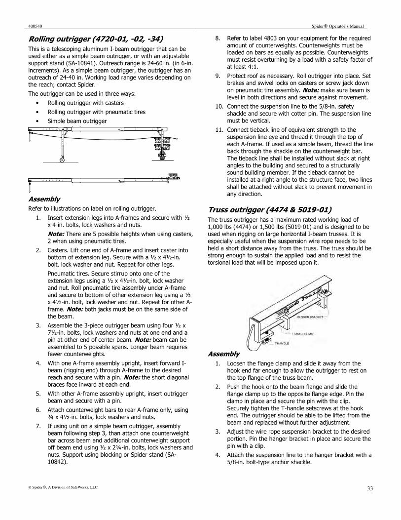
400540 Spider� Operator’s Manual
© Spider�, A Division of SafeWorks, LLC. 33
Rolling outrigger (4720-01, -02, -34)
This is a telescoping aluminum I-beam outrigger that can be used either as a simple beam outrigger, or with an adjustable
support stand (SA-10841). Outreach range is 24-60 in. (in 6-in.
increments). As a simple beam outrigger, the outrigger has an outreach of 24-40 in. Working load range varies depending on
the reach; contact Spider.
The outrigger can be used in three ways:
• Rolling outrigger with casters
• Rolling outrigger with pneumatic tires
• Simple beam outrigger
Assembly
Refer to illustrations on label on rolling outrigger.
1. Insert extension legs into A-frames and secure with ½ x 4-in. bolts, lock washers and nuts.
Note: There are 5 possible heights when using casters, 2 when using pneumatic tires.
2. Casters. Lift one end of A-frame and insert caster into bottom of extension leg. Secure with a ½ x 4½-in.
bolt, lock washer and nut. Repeat for other legs.
Pneumatic tires. Secure stirrup onto one of the
extension legs using a ½ x 4½-in. bolt, lock washer and nut. Roll pneumatic tire assembly under A-frame
and secure to bottom of other extension leg using a ½ x 4½-in. bolt, lock washer and nut. Repeat for other A-
frame. Note: both jacks must be on the same side of the beam.
3. Assemble the 3-piece outrigger beam using four ½ x
7½-in. bolts, lock washers and nuts at one end and a pin at other end of center beam. Note: beam can be
assembled to 5 possible spans. Longer beam requires fewer counterweights.
4. With one A-frame assembly upright, insert forward I-beam (rigging end) through A-frame to the desired
reach and secure with a pin. Note: the short diagonal braces face inward at each end.
5. With other A-frame assembly upright, insert outrigger beam and secure with a pin.
6. Attach counterweight bars to rear A-frame only, using ¾ x 4½-in. bolts, lock washers and nuts.
7. If using unit on a simple beam outrigger, assembly beam following step 3, than attach one counterweight
bar across beam and additional counterweight support off beam end using ½ x 2¼-in. bolts, lock washers and
nuts. Support using blocking or Spider stand (SA-10842).
8. Refer to label 4803 on your equipment for the required
amount of counterweights. Counterweights must be loaded on bars as equally as possible. Counterweights
must resist overturning by a load with a safety factor of at least 4:1.
9. Protect roof as necessary. Roll outrigger into place. Set brakes and swivel locks on casters or screw jack down
on pneumatic tire assembly. Note: make sure beam is
level in both directions and secure against movement.
10. Connect the suspension line to the 5/8-in. safety shackle and secure with cotter pin. The suspension line must be vertical.
11. Connect tieback line of equivalent strength to the suspension line eye and thread it through the top of
each A-frame. If used as a simple beam, thread the line back through the shackle on the counterweight bar.
The tieback line shall be installed without slack at right angles to the building and secured to a structurally
sound building member. If the tieback cannot be installed at a right angle to the structure face, two lines
shall be attached without slack to prevent movement in any direction.
Truss outrigger (4474 & 5019-01)
The truss outrigger has a maximum rated working load of 1,000 lbs (4474) or 1,500 lbs (5019-01) and is designed to be
used when rigging on large horizontal I-beam trusses. It is especially useful when the suspension wire rope needs to be
held a short distance away from the truss. The truss should be strong enough to sustain the applied load and to resist the
torsional load that will be imposed upon it.
Assembly
1. Loosen the flange clamp and slide it away from the hook end far enough to allow the outrigger to rest on
the top flange of the truss beam.
2. Push the hook onto the beam flange and slide the
flange clamp up to the opposite flange edge. Pin the clamp in place and secure the pin with the clip.
Securely tighten the T-handle setscrews at the hook end. The outrigger should be able to be lifted from the
beam and replaced without further adjustment.
3. Adjust the wire rope suspension bracket to the desired
portion. Pin the hanger bracket in place and secure the pin with a clip.
4. Attach the suspension line to the hanger bracket with a 5/8-in. bolt-type anchor shackle.

Spider� Operator’s Manual 400540
34 © Spider�, A Division of SafeWorks, LLC.
Rigging hook (SA-1001 & SA-1073) Rigging hooks are designed for structural steel
applications, particularly for I- and H-beams, and have a maximum rated working load of
1,500 lbs. The two models are for different sized beams. Use SA-1001 (identified by the
slight dog leg shape of the eye) on beams with flanges wider than 6 in. Use SA-1073 on
beams with flanges wider than 4 in.
Assembly
1. Thread the eye of the wire rope up through both hooks.
2. Pull the wire rope eye over the top of the second hook and seat it into place in the back of the hook.
To attach the hook to a beam set the fixed hook
over one edge of the lower flange while placing the sliding hook over the opposite edge. Pull down hard on
the wire rope to set the hook in place.
Roof hooks Cornice hook (700558-12 and 700558-21)
Cornice hooks support the vertically hung suspension wire rope of a staging from a cornice or parapet. Cornice hook 700558-
12 will fit a structure up to 12 in.; 700558-21 will fit up to 21 inches.
Both models have a maximum rated working load of 1,250 lbs. when used in the cornice or point-loaded condition. The
parapet or cornice must be able to sustain the maximum rated working load with a safety factor of 4:1.
Assembly
1. Place the hook over
the cornice or parapet wall with a block of
wood between the
point of the hook and the wall.
2. Attach the suspension wire rope to the hook
with a shackle, and hold it away from the
wall far enough to allow it to pass straight through the staging wire rope
guide. You might need to use a standoff attachment. The standoff can be supplied with your Spider hook.
3. Tiebacks with strength equivalent to the hoisting ropes shall be installed without slack at right angles to the
building and firmly secured to a structurally sound portion of the structure.
Parapet clamp (9-92 & 8-0044)
Parapet clamps are designed to support a suspension wire rope from a structural building parapet. Clamp 9-92 has a
maximum rated load of 1,000 lbs; 8-0044 has a maximum rated load of 1,500 lbs. The building parapet must be capable
of supporting the maximum rated load with a safety factor of
4. The reach on 9-92 is a maximum of 20 in., while the reach
on 8-0044 is 24 in. maximum.
Assembly
1. Verify the structural integrity of the parapet and the tieback attachment before rigging.
2. Adjust the position of the front clamp and hanger bracket to achieve the required reach.
3. Turn the clamping screw so the plate is against the rear bracket. Adjust the rear bracket to match the thickness
of the parapet.
4. Position the clamp over the parapet. Tighten the
clamping screw to a maximum of 10 ft-lbs.
5. Attach the tieback line, making sure it is taut:
• On Model 9-92, attach to the tieback bolt.
• On Model 8-0044, attach to the eye splice of the
safety cable as it extends from the back of the assembly.
6. Attach the suspension wire rope to the hanger bracket. Use only bolt-type anchor shackles. Tighten and secure
all fasteners and shackles before using.

400540 Spider� Operator’s Manual
© Spider�, A Division of SafeWorks, LLC. 35
WARNING Do not point load the parapet hook. Refer to label 700807
when rigging parapet hooks 700770-1, 700772-1 & 700773-1.
Parapet hooks
Parapet hooks support the vertically hung suspension wire rope of a staging from a parapet. The parapet must be able to
sustain the maximum rated load with a safety factor of 4.
Model Max. Parapet Thickness (in.)
Max. Load (lbs.)
SA-1086R 13 1000
SA-1087R 20 1000
700770-1 12 1500
700772-1 13-19 1500
700773-1 20-26 1500
Assembly
1. Place the hook
over the parapet wall, with a block
of wood between the point of the
hook and the wall.
2. Attach the suspension wire
rope to the hook with a shackle, and hold it away from the wall far enough to allow it to pass straight through
the staging wire rope guide. You may need to use a
standoff attachment. The standoff can be supplied with your Spider hook.
3. Tiebacks with strength equivalent to the hoisting ropes shall be installed without slack at right angles to the
building and firmly secured to a structurally sound portion of the structure.
If the tieback cannot be installed at right angles to the structure face, two tiebacks, attached at opposing
angles without slack, shall be attached to each rope-supporting device to prevent movement in any
direction.
Shackle The shackle is for attaching the suspension wire rope eye to
the rigging device when the rigging device does not provide for ready attachment. Use only bolt-type safety shackles; a 5/8-in.
shackle is the minimum size that should be used and will fit most rigging devices.
Installation
The wire rope can hang on either the shackle or the pin
depending on the rigging device. Make sure the bolt is placed through the shackle, the nut is installed, and it is secured with
the cotter pin.
Stirrup (008810-1) The adjustable stirrup allows for more flexibility in rigging the
platform. The stirrup can be placed anywhere along the length of a platform, except at connection. This allows the stirrup to
match existing rigging points. End gates are usually required to block off the open ends of the platform (see End Gate).
Cantilevering the ends of the platform is also possible, within limits. Contact your local Spider representative for more
information. Do not exceed the 1,500 lb. maximum lifting capacity of the stirrup.
Assembly
1. Remove locking bar and lay stirrup flat on the ground.
2. Place the mod platform section onto the bottom tube of
the stirrup. Rotate the stirrup to the upright position.
3. Position the stirrup stub securely onto midrail of
platform.
4. Insert locking bar into stirrup pocket; insert locking pin
and hair clip.
5. Reeve suspension wire rope through top housing, making sure it is seated on sheaves, and then reeve it
through the traction hoist.
6. If using secondary wire ropes, reeve rope through top
housing. Use the other set of sheaves, making sure the rope is seated on the sheaves, then reeve through the
secondary brake on the hoist.
7. Raise hoist to mounting position and secure both
mounting bolts. Adjust the top housing so that platform is level when suspended. Only adjust the platform
when the wire rope is slack.
Cantilever load limits
Refer to the cantilever platform chart label, 700117-1. This label provides allowable platform configurations, and the
cantilever lengths, load ratings, and weights for each
configuration. Contact Spider for more information.

Spider� Operator’s Manual 400540
36 © Spider�, A Division of SafeWorks, LLC.
Always use a safety harness and lanyard attached to an independent personnel safety line. Make sure the line is protected from any sharp edges and is secured to an
independent safety tieback.
Do not use this equipment in any manner other than described here and on label 700527-1. Consult local safety regulatory agencies for additional requirements specific to
your area.
WARNING The double shackle is meant only as a safety backup. It
should not be used as a primary transfer rigging.
Tank top rollers Pin style (700525-1)
The tank top roller supports the suspension wire rope of a vertically hung staging from the roof of a storage tank. The
maximum rated working load is 1,500 lbs.
Assembly
1. Verify with the structural engineer that the tank can safely support the rim and tieback loads listed below
without permanent damage.
Rated Load (lbs.) Rim Load (lbs.)A Tieback loads (lbs.)AB
1000 5500 4000
1250 7000 5000
1500 8500 6000
A – these loads include a safety factor of 4 based on the rated load. AB – combine tieback loads if more than one tank top roller is used.
[Example – if two are used at 1250 lbs. ea (rated load), 2 x 5000 lbs (tieback load) = 10,000 lbs.)
2. Position tank top roller as shown on label 700527-1. Maximum overhand distance must not exceed 19.5 in.,
measured from the suspension point to the edge of the tank with no slack in the tieback line.
3. Attach the tieback line from the tank roller to the
center tank support. Use only industry approved IWRC wire rope with a breaking strength greater than 9,000
lbs. Use only industry approved thimbles and fist grips. DO NOT SUBSTITUTE.
4. Torque all fist grips to manufacturer’s specifications: 30 ft-lbs for 5/16 wire rope; 45 ft-lbs. for 3/8 wire rope.
5. Proof-load the complete structure at 125% of the rated load. Maximum reach should not exceed 12 in. from
edge of tank.
6. Inspect tank, roller, and rigging for any signs of
damage. Retorque all fist grips and recheck the 19.5 in. dimension under the no-load condition. This should be
done at the start of each work shift. Do not use the equipment if anything is damaged.
WARNING
Transfer chain (SA-1002) The transfer chain is intended to support the weight of any
Spider staging that is equipped with a chain guard on the fairlead. Its primary use is horizontal movement through
structural steel, but can also be used for changing the suspension wire rope rigging location when you can’t bring the
staging down to ground level. It has a maximum rated working load of 1,500 lbs.
Assembly
1. Pass the grab hook end of the chain through both legs
of the tripod at the chain guard location. Be sure the
chain goes through both loops on the chain guard. The loops are supports for the chain when not in use. Do
not hang from loops.
2. Attach the grab hook onto any link of the chain below
the rigging hook so that it forms a loop around the two legs of the tripod. Rig the double shackle safety so that
each shackle is on one leg of the chain loop above the tripod chain guard. The length of the chain loop is
determined by the rigging application.
3. Place the rigging hook (slip hook) over one edge of the
beam flange and the free hook (sling hook) over the other edge.
4. Lower the staging until its weight is on the chain and the suspension wire rope has enough slack to allow the
rigging equipment to be moved. Be sure to hold the
wire rope to keep it from going slack on the drum. Use the tension-holding device if necessary.
5. The only time you will have to remove the suspension wire rope rigging from the beam is to get around an
obstruction.

400540 Spider� Operator’s Manual
© Spider�, A Division of SafeWorks, LLC. 37
Wire rope insulator (4897 or 4904) When welding from a suspended stage, it is important to
insulate the wire rope from the overhead rigging. When used together with the arc guard kit, the chances of inadvertently
cutting the wire rope with the welding arc are virtually eliminated. Observe the cautions regarding welding from
suspended staging (see complete list of precautions at the beginning of this manual).
Assembly
1. Attach one eye of the insulator assembly to the over-head rigging point. It may be necessary to use a bolt-
type anchor shackle.
2. Attach the other eye of the insulator assembly to the
suspension wire rope. Use a bolt-type anchor shackle.
3. Secure and tighten the bolt, nut, and cotter pins of the
shackles. Inspect the ceramic insulator block—do not use if damaged.
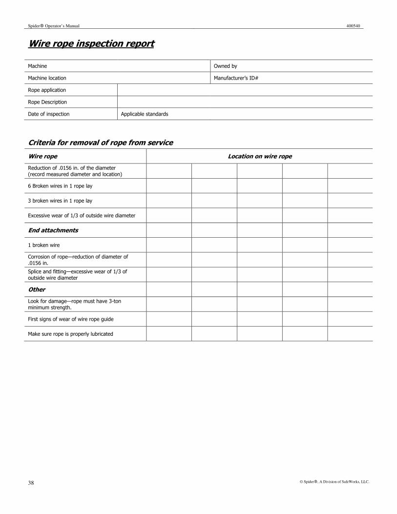
Spider� Operator’s Manual 400540
38 © Spider�, A Division of SafeWorks, LLC.
Wire rope inspection report
Machine Owned by
Machine location Manufacturer’s ID#
Rope application
Rope Description
Date of inspection Applicable standards
Criteria for removal of rope from service
Wire rope Location on wire rope
Reduction of .0156 in. of the diameter (record measured diameter and location)
6 Broken wires in 1 rope lay
3 broken wires in 1 rope lay
Excessive wear of 1/3 of outside wire diameter
End attachments
1 broken wire
Corrosion of rope—reduction of diameter of .0156 in.
Splice and fitting—excessive wear of 1/3 of outside wire diameter
Other
Look for damage—rope must have 3-ton minimum strength.
First signs of wear of wire rope guide
Make sure rope is properly lubricated