Embed Size (px)
Citation preview
SPHERES, Jülich's high-flux neutron backscattering spectrometer at FRMIIJoachim Wuttke, Alfred Budwig, Matthias Drochner, Hans Kämmerling, Franz-Joseph Kayser et al. Citation: Rev. Sci. Instrum. 83, 075109 (2012); doi: 10.1063/1.4732806 View online: http://dx.doi.org/10.1063/1.4732806 View Table of Contents: http://rsi.aip.org/resource/1/RSINAK/v83/i7 Published by the American Institute of Physics. Additional information on Rev. Sci. Instrum.Journal Homepage: http://rsi.aip.org Journal Information: http://rsi.aip.org/about/about_the_journal Top downloads: http://rsi.aip.org/features/most_downloaded Information for Authors: http://rsi.aip.org/authors
Downloaded 16 May 2013 to 134.94.122.141. This article is copyrighted as indicated in the abstract. Reuse of AIP content is subject to the terms at: http://rsi.aip.org/about/rights_and_permissions
REVIEW OF SCIENTIFIC INSTRUMENTS 83, 075109 (2012)
SPHERES, Jülich’s high-flux neutron backscattering spectrometer at FRM IIJoachim Wuttke,a) Alfred Budwig, Matthias Drochner, Hans Kämmerling,Franz-Joseph Kayser, Harald Kleines, Vladimir Ossovyi, Luis Carlos Pardo,b)
Michael Prager,c) Dieter Richter, Gerald J. Schneider, Harald Schneider,and Simon StaringerForschungszentrum Jülich GmbH, 52425 Jülich, Germany
(Received 16 April 2012; accepted 15 June 2012; published online 18 July 2012)
SPHERES is a third-generation neutron backscattering spectrometer, located at the 20 MW Germanneutron source FRM II and operated by the Jülich Centre for Neutron Science. It offers an energyresolution (fwhm) better than 0.65 μeV, a dynamic range of ± 31 μeV, and a signal-to-noise ratio ofup to 1750:1. © 2012 American Institute of Physics. [http://dx.doi.org/10.1063/1.4732806]
I. INTRODUCTION
Neutron backscattering is a versatile technique for mea-suring the dynamics of spins, atoms, and molecules on a GHzscale. Typical applications include hyperfine interactions inmagnetic materials, molecular rotations, diffusion, and relax-ation in complex systems.1, 2
Historically, three instrument generations can be distin-guished. Proposed by Maier-Leibnitz in 1966 (Ref. 3), neu-tron backscattering was first realized in a test setup at the4 MW reactor FRM (Garching, Germany). Count rates wereof the order of 1 h−1 and the signal-to-noise ratio was 2:1at best so that it took several weeks to measure a singlespectrum.4 Following this demonstration of principle, first-generation backscattering spectrometers were build at Jülich(“π -Spektrometer”5) and Grenoble (IN10 (Refs. 6–8), IN13(Ref. 9)); they were reviewed in Refs. 1 and 10–12.
In the second-generation instrument IN16 of InstitutLaue-Langevin (ILL) at Grenoble, consequent use of fo-cussing optics has been made; in it, a deflector chopper allowsto operate a spherical monochromator in exact backscatteringgeometry.13–15 Another instrument of this type is planned tobe built at the Australian research reactor OPAL (Ref. 16).
In third-generation spectrometers, the focussing optics ismade even more efficient by a phase-space transform (PST)chopper. This device, invented by Schelten and Alefeld in1984 (Ref. 17), enhances the neutron spectrum available atthe monochromator, and allows for a particularly compactinstrument design. The first realisation has been the high-flux backscattering spectrometer (HFBS) at the National In-stitute of Standards and Technology (NIST, Gaithersburg,Md.).18, 19
In this article, we present SPHERES, the SPectrom-eter for High Energy RESolution, built and operated byJCNS (Jülich Centre for Neutron Science) at FRM II
a)Electronic mail: [email protected])Permanent address: Grup de Caracterització de Materials, Departament
de Física i Enginyeria Nuclear, Universitat Politècnica de Catalunya,Barcelona, Spain.
c)Deceased in 2008.
(Forschungsneutronenquelle Heinz Maier-Leibnitz of Tech-nische Universität München at Garching, Germany). A thirdPST based backscattering instrument, named IN16B, is cur-rently under construction at the ILL where it will replace bothIN10 and IN16 (Refs. 20 and 21).
The development of SPHERES has been documented inseveral papers.22–27 First productive experiments were per-formed in June 2007, and routine operation started in April2008. Since then, two thirds of the beam time is offered toexternal users. Experiment proposals are invited twice a yearthrough the JCNS user office. By now (March 2012), nearly100 experiments have been performed, and more than 20 pa-pers have appeared. In the following, we describe the designof SPHERES, its hardware and software components, and itsperformance characteristics. The supplementary material con-tains a list of suppliers and some technical details.29
II. INSTRUMENT DESIGN
A. Instrument layout
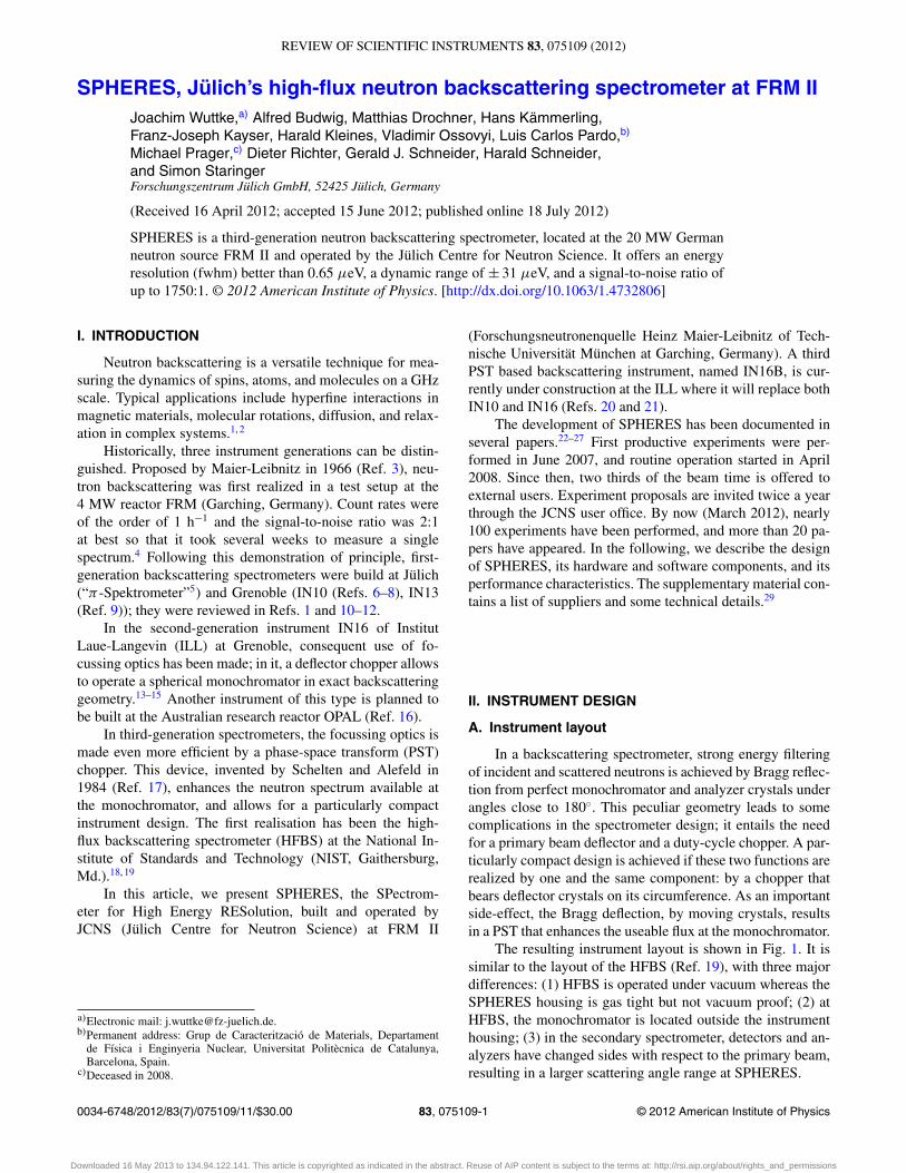
In a backscattering spectrometer, strong energy filteringof incident and scattered neutrons is achieved by Bragg reflec-tion from perfect monochromator and analyzer crystals underangles close to 180◦. This peculiar geometry leads to somecomplications in the spectrometer design; it entails the needfor a primary beam deflector and a duty-cycle chopper. A par-ticularly compact design is achieved if these two functions arerealized by one and the same component: by a chopper thatbears deflector crystals on its circumference. As an importantside-effect, the Bragg deflection, by moving crystals, resultsin a PST that enhances the useable flux at the monochromator.
The resulting instrument layout is shown in Fig. 1. It issimilar to the layout of the HFBS (Ref. 19), with three majordifferences: (1) HFBS is operated under vacuum whereas theSPHERES housing is gas tight but not vacuum proof; (2) atHFBS, the monochromator is located outside the instrumenthousing; (3) in the secondary spectrometer, detectors and an-alyzers have changed sides with respect to the primary beam,resulting in a larger scattering angle range at SPHERES.
0034-6748/2012/83(7)/075109/11/$30.00 © 2012 American Institute of Physics83, 075109-1
Downloaded 16 May 2013 to 134.94.122.141. This article is copyrighted as indicated in the abstract. Reuse of AIP content is subject to the terms at: http://rsi.aip.org/about/rights_and_permissions
075109-2 Wuttke et al. Rev. Sci. Instrum. 83, 075109 (2012)
NL6a
shutter
velocity selector
focussing guide
PST choppervacuum chamber
detectors
beamstop
sample
monochromator
Doppler driveanalysers
door
FIG. 1. Basic layout of SPHERES.
B. Crystal choices
The basic design decision for a backscattering spectrom-eter is the choice of the monochromator and analyzer crystals.Initially, SPHERES was foreseen to be convertible between aSi(111) and a Si(311) configuration. Si(111) is the standard atmost backscattering spectrometers. The shorter wavelength ofSi(311) gives access to a larger range in the scattering wavenumber q, with promising application niches in the study ofdiffusion on very short length scales.30, 31 However, the lowerresolution (which goes with λ−2) and background problemsfrom Bragg reflections (for instance, from sample holders orfrom cryostat walls) have so far prevented wide-spread us-age. In commissioning SPHERES, the original mechanicshad to be modified in many details in order to block neu-tronic background channels and to provide biological shield-ing. As a result, the instrument has lost its convertibility;the Si(311) option has been abandoned for the foreseeablefuture.
Another important choice is pyrolitic graphite (PG) forthe deflector crystals. Once deflector, monochromator, andanalzyer crystals are chosen, the neutronic parameters listedin Table I are fixed. The angle 2α0 between incoming anddeflected beam is obtained from the Bragg equation 2cos α0
= λ/(c/l), where c = 6.710 Å is the lattice constant of PG, andl the order of the Bragg reflection [00l].
TABLE I. Parameters that depend on the choice of Bragg reflections forenergy selection and deflection. The current configuration of SPHERES usessilicon (111) in monochromator and analyzers and pyrolitic graphite (002) asdeflector.
Bragg reflection for energy selection Si(111) Si(311)
Final neutron wavelength λf (Å) 6.271 3.275Final neutron energy Ef (meV) 2.080 7.626Final neutron velocity vf (m/s) 630.9 1208Bragg reflection for deflection PG(002) PG(004)Deflection angle 2α0 (◦) 41.65 25.14Schelten-Alefeld velocity v0 (m/s) 300.1 290.5
monochr.
sample
analyzer
sampledetector
chopper
chopper
slop
e: v
= 6
30 m
/s
4 m
4 m
12.7 ms
(a) f1 = 79 Hz
12.7 ms
(b) f2 = 237 Hz
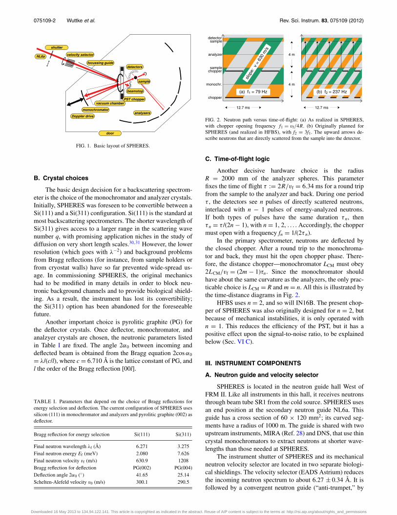
FIG. 2. Neutron path versus time-of-flight: (a) As realized in SPHERES,with chopper opening frequency f1 = vf/4R. (b) Originally planned forSPHERES (and realized in HFBS), with f2 = 3f1. The upward arrows de-scribe neutrons that are directly scattered from the sample into the detector.
C. Time-of-flight logic
Another decisive hardware choice is the radiusR = 2000 mm of the analyzer spheres. This parameterfixes the time of flight τ := 2R/vf = 6.34 ms for a round tripfrom the sample to the analyzer and back. During one periodτ , the detectors see n pulses of directly scattered neutrons,interlaced with n − 1 pulses of energy-analyzed neutrons.If both types of pulses have the same duration τ n, thenτ n = τ /(2n − 1), with n = 1, 2, . . . . Accordingly, the choppermust open with a frequency fn = 1/(2τ n).
In the primary spectrometer, neutrons are deflected bythe closed chopper. After a round trip to the monochroma-tor and back, they must hit the open chopper phase. There-fore, the distance chopper—monochromator LCM must obey2LCM/vf = (2m − 1)τn. Since the monochromator shouldhave about the same curvature as the analyzers, the only prac-ticable choice is LCM = R and m = n. All this is illustrated bythe time-distance diagrams in Fig. 2.
HFBS uses n = 2, and so will IN16B. The present chop-per of SPHERES was also originally designed for n = 2, butbecause of mechanical instabilities, it is only operated withn = 1. This reduces the efficiency of the PST, but it has apositive effect upon the signal-to-noise ratio, to be explainedbelow (Sec. VI C).
III. INSTRUMENT COMPONENTS
A. Neutron guide and velocity selector
SPHERES is located in the neutron guide hall West ofFRM II. Like all instruments in this hall, it receives neutronsthrough beam tube SR1 from the cold source. SPHERES usesan end position at the secondary neutron guide NL6a. Thisguide has a cross section of 60 × 120 mm2; its curved seg-ments have a radius of 1000 m. The guide is shared with twoupstream instruments, MIRA (Ref. 28) and DNS, that use thincrystal monochromators to extract neutrons at shorter wave-lengths than those needed at SPHERES.
The instrument shutter of SPHERES and its mechanicalneutron velocity selector are located in two separate biologi-cal shieldings. The velocity selector (EADS Astrium) reducesthe incoming neutron spectrum to about 6.27 ± 0.34 Å. It isfollowed by a convergent neutron guide (“anti-trumpet,” by
Downloaded 16 May 2013 to 134.94.122.141. This article is copyrighted as indicated in the abstract. Reuse of AIP content is subject to the terms at: http://rsi.aip.org/about/rights_and_permissions
075109-3 Wuttke et al. Rev. Sci. Instrum. 83, 075109 (2012)
S–DH) that reduces the beam section by a factor of 11.5 to25 × 25 mm2. Neutrons leave this guide system with a diver-gence of about ± 47 mrad horizontal, ± 64 mrad vertical. Fordetails on all this, see the supplementary material.29
B. Phase-space transform chopper
The PST chopper is the key component of a third-generation backscattering spectrometer. As said above, itcombines the functionalities of a beam deflector and of a duty-cycle chopper. Half of its circumference bears deflector crys-tals that redirect incoming neutrons towards the monochroma-tor. The other half circumference is open. When the chopperis open, neutrons coming out of the neutron guide are trans-mitted towards a beam stop that is integrated in the chopperhousing, and neutrons coming back from the monochromatorare transmitted towards the sample.
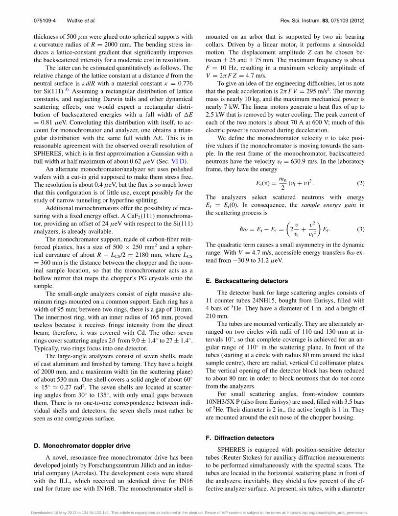
To enable spectral scans, a sufficiently large wavelengthband must be forwarded towards the monochromator. Thisrequires deflector crystals with large mosaicity. PG crystals,specified for a mosaicity of 2.5◦ fwhm (Advanced Ceram-ics), were selected according to rocking curves measured one-by-one on the triple-axis neutron spectrometer UNIDAS atJülich. To further enhance the horizontal mosaicity, the crys-tals are assembled in stacks of three, with tilts of 0◦, +2.5◦,and −2.5◦ imposed by aluminum wedges (Fig. 3).
Intensity and width of the forwarded neutron band arefurther enhanced by the horizontal motion of the deflec-tor crystals. This phase-space transformation “from white towide” has first been suggested in a conference proceedings oflimited circulation;17 an easily accessible summary has beenprovided in Ref. 19. The Bragg reflection, by moving mosaiccrystals, compresses the energy distribution and thereby en-hances the flux in the acceptance range of the backscatteringmonochromator. In accordance with “Liouville’s theorem,”the compression of the energy distribution is accompanied bya widening of the angular distribution. This is not a severe
PG
B4C
Al
steel
FIG. 3. Deflector crystal assembly in the PST chopper. In both drawings, theneutrons come from the left. Left drawing: cross section. Right drawing: viewfrom outside towards the chopper axis (the closing Al element and the screwsare not shown). The deflector stacks consist of three pyrolitic graphite mosaiccrystals, tilted by aluminum wedges, and followed by a 10B4C absorber plate.
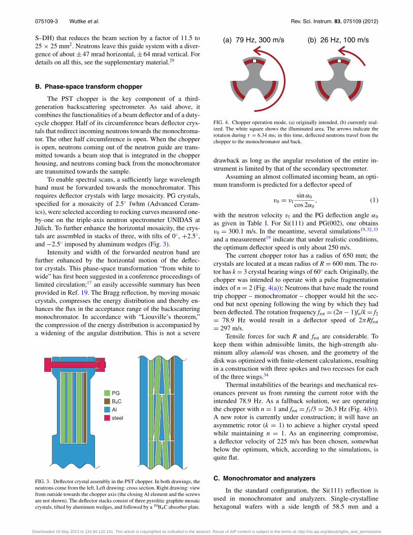
(a) 79 Hz, 300 m/s (b) 26 Hz, 100 m/s
FIG. 4. Chopper operation mode, (a) originally intended, (b) currently real-ized. The white square shows the illuminated area. The arrows indicate therotation during τ = 6.34 ms; in this time, deflected neutrons travel from thechopper to the monochromator and back.
drawback as long as the angular resolution of the entire in-strument is limited by that of the secondary spectrometer.
Assuming an almost collimated incoming beam, an opti-mum transform is predicted for a deflector speed of
v0 = vfsin α0
cos 2α0, (1)
with the neutron velocity vf and the PG deflection angle α0
as given in Table I. For Si(111) and PG(002), one obtainsv0 = 300.1 m/s. In the meantime, several simulations19, 32, 33
and a measurement19 indicate that under realistic conditions,the optimum deflector speed is only about 250 m/s.
The current chopper rotor has a radius of 650 mm; thecrystals are located at a mean radius of R = 600 mm. The ro-tor has k = 3 crystal bearing wings of 60◦ each. Originally, thechopper was intended to operate with a pulse fragmentationindex of n = 2 (Fig. 4(a)): Neutrons that have made the roundtrip chopper – monochromator – chopper would hit the sec-ond but next opening following the wing by which they hadbeen deflected. The rotation frequency frot = (2n − 1)fn/k = f2= 78.9 Hz would result in a deflector speed of 2πRfrot
= 297 m/s.Tensile forces for such R and frot are considerable. To
keep them within admissible limits, the high-strength alu-minum alloy alumold was chosen, and the geometry of thedisk was optimized with finite-element calculations, resultingin a construction with three spokes and two recesses for eachof the three wings.34
Thermal instabilities of the bearings and mechanical res-onances prevent us from running the current rotor with theintended 78.9 Hz. As a fallback solution, we are operatingthe chopper with n = 1 and frot = f1/3 = 26.3 Hz (Fig. 4(b)).A new rotor is currently under construction; it will have anasymmetric rotor (k = 1) to achieve a higher crystal speedwhile maintaining n = 1. As an engineering compromise,a deflector velocity of 225 m/s has been chosen, somewhatbelow the optimum, which, according to the simulations, isquite flat.
C. Monochromator and analyzers
In the standard configuration, the Si(111) reflection isused in monochromator and analyzers. Single-crystallinehexagonal wafers with a side length of 58.5 mm and a
Downloaded 16 May 2013 to 134.94.122.141. This article is copyrighted as indicated in the abstract. Reuse of AIP content is subject to the terms at: http://rsi.aip.org/about/rights_and_permissions
075109-4 Wuttke et al. Rev. Sci. Instrum. 83, 075109 (2012)
thickness of 500 μm were glued onto spherical supports witha curvature radius of R = 2000 mm. The bending stress in-duces a lattice-constant gradient that significantly improvesthe backscattered intensity for a moderate cost in resolution.
The latter can be estimated quantitatively as follows. Therelative change of the lattice constant at a distance d from theneutral surface is κd/R with a material constant κ = 0.776for Si(111).35 Assuming a rectangular distribution of latticeconstants, and neglecting Darwin tails and other dynamicalscattering effects, one would expect a rectangular distri-bution of backscattered energies with a full width of �E= 0.81 μeV. Convoluting this distribution with itself, to ac-count for monochromator and analyzer, one obtains a trian-gular distribution with the same full width �E. This is inreasonable agreement with the observed overall resolution ofSPHERES, which is in first approximation a Gaussian with afull width at half maximum of about 0.62 μeV (Sec. VI D).
An alternate monochromator/analyzer set uses polishedwafers with a cut-in grid supposed to make them stress free.The resolution is about 0.4 μeV, but the flux is so much lowerthat this configuration is of little use, except possibly for thestudy of narrow tunneling or hyperfine splitting.
Additional monochromators offer the possibility of mea-suring with a fixed energy offset. A CaF2(111) monochroma-tor, providing an offset of 24 μeV with respect to the Si(111)analyzers, is already available.
The monochromator support, made of carbon-fiber rein-forced plastics, has a size of 500 × 250 mm2 and a spher-ical curvature of about R + LCS/2 = 2180 mm, where LCS
= 360 mm is the distance between the chopper and the nom-inal sample location, so that the monochromator acts as ahollow mirror that maps the chopper’s PG crystals onto thesample.
The small-angle analyzers consist of eight massive alu-minum rings mounted on a common support. Each ring has awidth of 95 mm; between two rings, there is a gap of 10 mm.The innermost ring, with an inner radius of 165 mm, proveduseless because it receives fringe intensity from the directbeam; therefore, it was covered with Cd. The other sevenrings cover scattering angles 2ϑ from 9.0 ± 1.4◦ to 27 ± 1.4◦.Typically, two rings focus into one detector.
The large-angle analyzers consist of seven shells, madeof cast aluminum and finished by turning. They have a heightof 2000 mm, and a maximum width (in the scattering plane)of about 530 mm. One shell covers a solid angle of about 60◦
× 15◦ � 0.27 rad2. The seven shells are located at scatter-ing angles from 30◦ to 135◦, with only small gaps betweenthem. There is no one-to-one correspondence between indi-vidual shells and detectors; the seven shells must rather beseen as one contiguous surface.
D. Monochromator doppler drive
A novel, resonance-free monochromator drive has beendeveloped jointly by Forschungszentrum Jülich and an indus-trial company (Aerolas). The development costs were sharedwith the ILL, which received an identical drive for IN16and for future use with IN16B. The monochromator shell is
mounted on an arbor that is supported by two air bearingcollars. Driven by a linear motor, it performs a sinusoidalmotion. The displacement amplitude Z can be chosen be-tween ± 25 and ± 75 mm. The maximum frequency is aboutF = 10 Hz, resulting in a maximum velocity amplitude ofV = 2πFZ = 4.7 m/s.
To give an idea of the engineering difficulties, let us notethat the peak acceleration is 2πFV = 295 m/s2. The movingmass is nearly 10 kg, and the maximum mechanical power isnearly 7 kW. The linear motors generate a heat flux of up to2.5 kW that is removed by water cooling. The peak current ofeach of the two motors is about 70 A at 600 V; much of thiselectric power is recovered during deceleration.
We define the monochromator velocity v to take posi-tive values if the monochromator is moving towards the sam-ple. In the rest frame of the monochromator, backscatteredneutrons have the velocity vf = 630.9 m/s. In the laboratoryframe, they have the energy
Ei(v) = mn
2(vf + v)2 . (2)
The analyzers select scattered neutrons with energyEf = Ei(0). In consequence, the sample energy gain inthe scattering process is
¯ω = Ei − Ef =(
2v
vf+ v2
vf2
)Ef. (3)
The quadratic term causes a small asymmetry in the dynamicrange. With V = 4.7 m/s, accessible energy transfers ¯ω ex-tend from −30.9 to 31.2 μeV.
E. Backscattering detectors
The detector bank for large scattering angles consists of11 counter tubes 24NH15, bought from Eurisys, filled with4 bars of 3He. They have a diameter of 1 in. and a height of210 mm.
The tubes are mounted vertically. They are alternately ar-ranged on two circles with radii of 110 and 130 mm at in-tervals 10◦, so that complete coverage is achieved for an an-gular range of 110◦ in the scattering plane. In front of thetubes (starting at a circle with radius 80 mm around the idealsample centre), there are radial, vertical Cd collimator plates.The vertical opening of the detector block has been reducedto about 80 mm in order to block neutrons that do not comefrom the analyzers.
For small scattering angles, front-window counters10NH3/5X P (also from Eurisys) are used, filled with 3.5 barsof 3He. Their diameter is 2 in., the active length is 1 in. Theyare mounted around the exit nose of the chopper housing.
F. Diffraction detectors
SPHERES is equipped with position-sensitive detectortubes (Reuter-Stokes) for auxiliary diffraction measurementsto be performed simultaneously with the spectral scans. Thetubes are located in the horizontal scattering plane in front ofthe analyzers; inevitably, they shield a few percent of the ef-fective analyzer surface. At present, six tubes, with a diameter
Downloaded 16 May 2013 to 134.94.122.141. This article is copyrighted as indicated in the abstract. Reuse of AIP content is subject to the terms at: http://rsi.aip.org/about/rights_and_permissions
075109-5 Wuttke et al. Rev. Sci. Instrum. 83, 075109 (2012)
of 1 in. and 535 mm of active length, provide a coverage ofscattering angles from about 30◦ to 120◦.
The resolution of this diffractometer is limited by thehorizontal spread of incident neutron directions, which in theworst case is ±(half monochromator width)/R = ± 250/2000= ±12.5%. This is acceptable because we do not aim forfull-fledged structure determination, but only for monitoringstructural changes.36
G. Instrument housing with argon filling
The instrument housing has a surface of about 36 m2,and a volume of nearly 60 m3. Its walls and ceiling are madeof steel plates of 5 mm thickness, anchored to a steel frame,and proven to be gas tight. Towards the inside, a 100 mmpolyethylene layer moderates fast neutrons. The innermostcladding of walls and ceiling consists of Cd plates of 1 mmthickness.
The housing is reasonably gas tight and equipped withpneumatics and controls so that it can be filled with argon.This reduces losses by air scattering in the secondary spec-trometer, where neutrons have to travel about 4.3 m throughatmosphere. In the primary spectrometer, another 0.3 m are inatmosphere; the remaining flight path is in a vacuum chamberthat prolongates the chopper casing towards the monochroma-tor, as indicated in Fig. 1. Displacing 90% of the air by argonleads to an intensity gain of more than 35%, in good accordwith expectations from tabulated neutron cross sections. Fortechnical details of the argon filling, see the supplementarymaterial.29
H. Sample environments
The standard sample environment, used for most experi-ments, is a cryostat SHI-950T (Janis). It is a closed-cycle re-frigerator system with cold head and compressor manufac-tured by Sumitomo Heavy Industries. In the low-temperaturerange from 4 K to 320 K, the sample is cooled via exchangegas. In the high-temperature range, from 290 K to 650 K(700 K for the limited amount of time), the system acts as acryofurnace, with the sample in vacuum. The sample tube hasa diameter of 60 mm; samples are allowed to have diametersof up to 55 mm.
The standard sample stick is equipped with Si diodesDT670A for temperatures from 4 K to 500 K. A high-temperature stick with Pt 1000 thermometers covers temper-atures from 10 K to 700 K. Gas-loading equipment is underpreparation.
Sample environments are inserted and operated from theplatform on top of the instrument housing. If the tail diam-eter exceeds 160 mm, the secondary spectrometer must betemporarily realigned to a sample position slightly out of thefocus of the monochromator. To change the sample environ-ment, it is unavoidable to break the argon atmosphere. There-fore, experiments with non-standard sample environments arepreferentially scheduled at the beginning or at the end of a re-actor cycle. So far, experiments have been performed with adilution cryostat that gives access to temperatures down to
30 mK. Other environments will be adapted and tried as re-quested by users.
IV. INSTRUMENT CONTROL AND DATA ACQUISITION
A. High-level user interface
During regular experiments, physical access to the instru-ment is needed only for changing samples. All other opera-tions can be performed remotely. A graphical user interface(GUI) allows:
� to open and close the instrument shutter,� to start and stop the monochromator drive, and to set
its velocity amplitude,� to set the sample temperature, and to start temperature
ramps,� to start and stop the data acquisition, to save files, and
to reset histograms, and� to submit, edit, start, and stop experiment scripts.
It displays:
� warnings and error messages,� the status of data acquisition, sample environment, and
peripheral systems,� current count rates for all detectors, separately for di-
rect, elastic, and inelastic scattering,� the latest acquired spectrum,� the latest acquired diffractogram,� the time evolution of various parameters in the last
hours or days, and� the status of experiment-script execution and the script
commands ahead.
As the instrument is operated from different workplaces(cabin in the neutron guide hall, office, home), there is nosimple way to maintain a traditional log book. Therefore, wehave replaced paper by digital storage, using a simple wikisystem37 as our instrument log. Besides, there are automati-cally generated event and parameter logs.
B. Instrument-control daemons
As a leading principle in the design of our instrument-control software, we requested that no neutrons should be lostbecause of peripheral software or network problems. There-fore, the instrument’s subsystems are controlled by a num-ber of independent background processes (daemons) that con-tinue to work even if the connection to upper-level processesis interrupted.
The following daemons are the most important ones:
� spectral data acquisition (Sec. IV D),� diffraction data acquisition (see the supplementary
material),29
� slow control daemon (Sec. IV E),� temperature-controller, supervising the sample-
environment temperature controller,� the Doppler driver, supervising the control PC supplied
by the manufacturer,
Downloaded 16 May 2013 to 134.94.122.141. This article is copyrighted as indicated in the abstract. Reuse of AIP content is subject to the terms at: http://rsi.aip.org/about/rights_and_permissions
075109-6 Wuttke et al. Rev. Sci. Instrum. 83, 075109 (2012)
� event logger, receiving log lines from other daemonsand writing them to an event log, thereby documentinguser interventions, experiment-script execution steps,system warnings, and error messages,
� parameter logger, querying every 30 s some 50 statusparameters from other daemons and writing them to aparameter log,
� documentation server and raw-data postprocessor(Sec. V A),
� script engine, executing user-written experimentscripts, and
� the GUI server through which data and commands arechanneled to and from the graphical user interface.
The spectral acquisition is time critical; therefore, it iswritten in the programming language C, and it is runningon a dedicated computer. For all other processes, computa-tional speed is less important than the clarity of code; there-fore, they are written in an expressive scripting language,Ruby.
All computers are connected by ethernet (instrumentLAN). Interprocess communication (IPC) is based on TCP(transmission control protocol) messages. Each daemon is lis-tening on a TCP port for commands given by other daemons.For instance, the spectral acquisition daemon receives com-mands (start, stop, save, reset) from the GUI server, and statusqueries from the parameter logger.
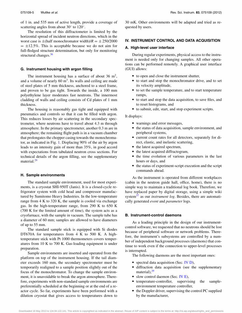
C. Spectral acquisition electronics
The data acquisition is done in a VME crate (Fig. 5)using components and software from Struck Innovative Sys-teme (SIS) (Ref. 38). The input consists of TTL pulses fromthe neutron-counter preamplifiers and from the optical en-coders sensing the translation of the monochromator Doppler
SHARCDSP
SIS3600
SIS3801
SIS3100
32 bitlatch
32x32 bitscaler VME
bus
IRQ
50 kHz
DRAM
Dopplerposition
PST chopperposition
detectorchannels
1 2
fiber
FIG. 5. The data acquisition VME crate.38 The signal processor on the SIS3100 sequencer board is a ADSP21061. An optical fiber connects the crate toa SIS 1100 PCI card on the dedicated data-acquisition PC.
drive (200 ticks per mm) and the rotation of the PST chop-per (2 0480 ticks per revolution). The Doppler and chopperticks are counted up and down in home-made counter boards,then they are transmitted to a 32 bit latch. The neutron countsare transmitted via a trivial home-made interface board to a32 × 32 scaler.
The sampling period is τ = 20 μs. Once every τ , a dig-ital signal processor reads the data from the latch and fromthe scaler, writes them to DRAM, and resets the scaler. Thedata form a fixed-length block of twenty 32-bit words. In thefollowing, each block shall be identified by an index i, cor-responding to a time ti = const + iτ . One word encodesthe Doppler position zi and the chopper phase χ i (16 bitseach); the remaining 19 words nji accommodate the neutroncounts from up to 19 detectors j. The DRAM is divided intotwo buffers with 1000 000 words each. It takes 50 000 datablocks or 1 s to fill one buffer. While one buffer is beingfilled, the other buffer is read out via an optical link by theupstream PC.
D. Spectral acquisition daemon
The data-acquisition PC (Opteron 2×2.4 GHz, 64-bit) isdedicated to running the spectral acquisition daemon. It accu-mulates and stores histograms containing neutron counts perenergy channel and per detector. These raw spectra are only afew correction steps (Sec. V B) away from the physical scat-tering law S(q, ω).
The daemon consists of an endless loop that waits forone of the two DRAM buffers on the VME crate to befilled. As soon as this is the case, its contents is read viathe optical link and pushed on a stack. When the stack cov-ers at least one Doppler oscillation period, it is processed.A sine function with four free parameters (offset, ampli-tude, frequency, phase) is fitted to the zi, using starting val-ues retained from the previous fit. Then, a loop over thedata blocks i is performed, to be described in the next threeparagraphs.
Depending on the chopper phase χ i, the data block isassigned a category c(χ i), which can be indirect, direct,or ambiguous, depending on whether or not the neutronshave travelled the detour sample–analyzer–sample or not. InSec. VI C, we will show how this categorization is set up.Ambiguous data blocks are not processed further.
To assign our scattering events to an energy channel ω,we need to know the time
t̂i = ti − (vf + v(t̂i))(L0i − z(t̂i)) − vfL
cf , (4)
at which the neutron has been backscattered by the monochro-mator. Here, ti is the detection time, and Li, f is the path trav-elled before and after scattering by the sample. The path Lc
fdepends on the category c: it is only about 10 cm in the di-rect case, but 4 m more in the indirect case. The path off-set z(t̂i) and the velocity modulation v(t̂i) are given by theposition and speed of the monochromator at time t̂i . Thismakes Eq. (4) nonlinear; it is most easily solved by itera-tion. For a given t̂i , the analytic derivative of the fit func-tion z(t) is used to obtain v(t̂i). Equation (3) then yieldsω(vi). A quick estimate shows that the delay t̂i − ti is not
Downloaded 16 May 2013 to 134.94.122.141. This article is copyrighted as indicated in the abstract. Reuse of AIP content is subject to the terms at: http://rsi.aip.org/about/rights_and_permissions
075109-7 Wuttke et al. Rev. Sci. Instrum. 83, 075109 (2012)
negligible: Neutrons in the indirect category travel more than6 m from the monochromator to the detector, which takesabout 10 ms, corresponding to up to 1/10 of a Dopplerperiod.
On starting the data acquisition for a given Dopplervelocity amplitude, an equidistant ω mesh has beenchosen, with channels [ωk − �ω/2, ωk + �ω/2].This makes it easy to determine the pertinent channelk(i) = �(ω(vi) − (ω0 − �ω/2))/�ω�. Finally, the neutronhistograms of the pertinent chopper category c(χ i) areincremented: Hc
jk ← Hcjk + nji for all detectors j. The time
spent in energy channel k(i) is incremented accordingly:Nc
k ← Nck + 1. Here ends the loop over i.
All these computations must be completed before thenext DRAM buffer is overwritten. After some optimizations,this requirement could be fulfilled with sufficient margin:In years of operation, not a single data block has beenlost because of computer overload. As a side product, aself-contained C library for Levenberg-Marquardt least-squares minimization has been released as an open-sourceproject,39 serving practitioners from all areas of science andengineering.
Our histogramming relies on the assumption that themotion of the monochromator accurately follows a simpleanalytic function. Analyses of recorded zi(ti) traces haveshown that the motion accomplished by the Aerolas Dopplerdrive is indeed almost perfectly sinusoidal, deviations beingnegligible on the scale set by the energy resolution of thespectrometer.
The accumulated histograms are written to files whena preset time interval has elapsed or when a save com-mand is received through the daemon’s IPC interface. Filesare saved to the local disk, which is remote readablethrough the network file system (NFS). The raw-spectra, asother data produced by SPHERES, are formatted as self-documenting YAML files. YAML is a data-serialization spec-ification with intrinsic support for basic data structures likearrays and hashes and with an emphasis on human read-ability; parsers are available for all major programminglanguages.40
E. Safety instrumentation and slow control
SPHERES is equipped with a fail-safe programmablelogic controller (Fehlersichere speicherprogrammierbareSteuerung F-SPS, Siemens Simatic S7 300F) for safetyinstrumentation and slow control.41 The F-SPS is connectedvia an internal bus or Profibus-DP to various sensors andactors. A touchpanel next to the instrument door provides astatus display; it provides the only regular user interface forsafety-critical subsystems like the door lock and the argonpneumatics.
A simple daemon running on a compact-PCI computercouples the F-SPS to the instrument LAN. It has read accessto all sensors and write access to safety-uncritical actors, in-cluding the shutter opener, which can be activated if the in-strument housing is closed and locked and a manual switch isin “remote control” position.
V. DATA PROCESSING
A. Raw-data postprocessor
The raw files produced by the spectral data-acquisitiondaemon contain the energy mesh ωk, the histograms Hc
jk
and Nck , some information about the instrument and data-
acquisition setup, and the date and time when the mea-surement was started and stopped. Had all other daemonscrashed, this would be sufficient to allow a valid data anal-ysis. In regular operation, however, users expect data files tocontain additional information like experiment title, samplename, and sample temperature. Since the spectral acquisi-tion daemon is deliberately kept ignorant about these things(not essential for its functioning, and potential sources ofbugs and failures), the wanted information must be addedex post.
This is done by the raw-data postprocessor. Running onanother computer than the spectral acquisition daemon, itreads a raw-spectrum file via NFS, and looks up the startand stop time entries. Then, it opens the parameter log, readsthe lines recorded during the spectral measurement, and com-putes mean value and standard deviation of the sample tem-perature and of some other parameters. Textual informationlike experiment title and sample name, usually entered by theuser via the GUI, is retrieved from another dedicated file sys-tem. All this is written to a user-friendly aggregated raw-datafile.
B. Raw-data reduction with SLAW
While some users want to work on the raw data, most askfor standard software to deliver normalized scattering lawsS(q, ω). To provide this service, a new raw-data reductionprogram SLAW (Ref. 42) has been developed. Compared tolegacy software like SQW of the ILL, SLAW offers better sup-port for four-dimensional data sets S(q, ω; T) or S(q, ω; t) ob-tained in time-resolved inelastic scans. Also, SLAW does notbind users to a specific data format; it supports a variety ofoutput formats, and new output routines can be easily addedad hoc.
SLAW is controlled by an input script that contains con-figuration commands and a map that assigns raw scans tooutput files. SLAW processes the raw data through the fol-lowing steps of which all but the first and the last areoptional:
� read raw data files, adding or subtracting subscans asneeded,
� perform binning in energy, scattering angle, or timeslots, possibly eliminating some of these dimensions,
� subtract empty-can measurement, optionally weightedwith a self-absorption factor,43
� normalize neutron counts Hcjk to the measuring time
Nck τ spent in a given energy channel,
� correct for incident flux variations (Sec. V C),� divide counts by the elastic intensity of a reference
measurement (usually vanadium or a low-temperaturemeasurement with the current sample), and
� save the scattering law.
Downloaded 16 May 2013 to 134.94.122.141. This article is copyrighted as indicated in the abstract. Reuse of AIP content is subject to the terms at: http://rsi.aip.org/about/rights_and_permissions
075109-8 Wuttke et al. Rev. Sci. Instrum. 83, 075109 (2012)
SLAW has alternative input routines to process rawdata from other backscattering spectrometers. Its structureis generic enough to allow future extension to time-of-flightspectrometers.
C. Instead of a monitor
Most inelastic neutron spectrometers have a high-transmission neutron counter, located a little upstream of thesample, to monitor the incoming flux. In SPHERES, the win-dows of such a monitor would cause undesirable background.We therefore prefer an indirect normalization.
We must account for two kinds of flux variation: tem-poral variations of the reactor power, of the filling of thecold source, and of the monochromator orientations of theupstream instruments, and spectral variations of the primaryspectrometer transmission. The temporal variations of the in-cident beam can be measured with good accuracy without in-serting any device into the beam: it is sufficient to monitorthe γ radiation emitted by the aluminum windows at the endof the convergent guide and at the chopper entry. Such a γ
monitor, still missing, will be installed soon.The spectral variation of the flux at the sample is de-
termined by a spectrum of the cold source, by the neutronguide system, by the velocity selector, and most importantly,by the PST chopper and the monochromator. To make thingsmore complicated, the angle of the Bragg deflection in thePST chopper is energy dependent, and the monochromator ismoving in space so that the geometric-optical focussing ontothe sample is imperfect, with a non-trivial interplay of energy,direction, and lateral spread. To account for all this, the spec-tral distribution of the incident flux is best measured either byplacing a neutron counter exactly at the sample position, or bycounting neutrons that are scattered from the sample directlyinto the regular detectors. The latter method is regularly usedas the “pseudomonitor” of SPHERES.
VI. PERFORMANCE
A. Flux and count rates
The incident flux at the end of the convergent neutronguide has been measured at two occasions with gold foil ac-tivation. The results were (1.85 ± 0.05) × 109 cm−2 s−1 inNovember 2005, and (1.19 ± 0.05) × 109 cm−2s−1 in Febru-ary 2012. A decrease of the order of 10% was to be ex-pected from the two breaks in the upstream neutron guide(Sec. III A). The remaining loss is not understood; it mustbe feared that the neutron guides have degraded substantially.To detect further degradation and to determine necessary ac-tion, it will be important to remeasure the flux more regularlyin the coming years.
The flux at the sample position is more difficult to mea-sure; for details see the supplementary material.29 The bestcurrent estimate is φsam = 1.8 × 10⁶ s−1 within a cross sec-tion of 25 × 40 mm2 for the open chopper state. The averageflux seen by a gold foil is only half of it.
For typical samples made for transmissions between 80%and 90%, elastic count rates φel are of the order 1000 s−1.
Here, as in the instrument’s GUI display, such numbers areper detector, and under the assumption that all time is spentcounting into this single channel. The pseudomonitor rate φdir
of neutrons that are directly scattered from the sample intothe detector, is about twice as large. Reasons why φel/φdir
is smaller than 1 include: solid angle mismatch (the detec-tor block has a larger solid angle than the analyzers, to ensurethat all backscattered neutrons have a chance to reach a de-tector), absorption and scattering losses in the sample (whichis traversed a second time by backscattered neutrons), lossesalong the 4 m from the detector to the analyzers and back,imperfect energy selection in the monochromator, and finitebackscattering probability in the analyzers.
B. Dark counts
Dark count rates in each of the large-angle detectors areof the order of 0.02 s−1 when the reactor is off, and 0.1 s−1
when the reactor is at 20 MW and the instrument shutterclosed. This is negligible compared to the background pro-duced in our primary spectrometer.
When the instrument shutter is open and the chopper isrunning, but the exit window of the chopper (just before thesample position) is closed by a Cd mask, then the dark countrates in the large-angle detectors are about 0.53 s−1. Only asmall part of this background is due to slow neutrons thatpenetrate from the primary into the secondary spectrometer,circumventing the chopper exit window. Most of the back-ground is independent of the chopper phase, which indicatesan origin between the shutter and the chopper. This has beenconfirmed by experimental tests: probably, a n–γ conversionin the supermirror coating of the focussing neutron guide isfollowed by a conversion to fast neutrons in the guide’s leadshielding.
C. Chopper modulation of count rates
Along with the duty-cycle chopper, a backscatteringspectrometer needs a time-of-flight logic to discriminate neu-trons that are backscattered by the analyzers from neutronsthat are scattered directly from the sample into the detec-tors. In SPHERES, this time-of-flight discrimination is per-formed by the spectral acquisition daemon (Sec. IV D),based on the chopper phase reading that is saved every 20 μsalong with the Doppler position reading and the neutroncounts.
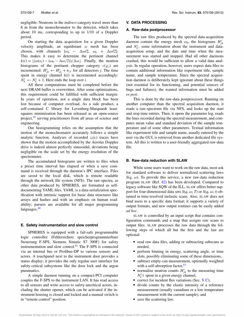
The parametrization of the discrimination must be de-termined empirically. A chopper-phase histogram is savedin each raw data file. This histogram is based on a rectan-gular grid with 120 chopper-phase channels, but only twoenergy channels, to distinguish roughly between elastic andinelastic scattering. Figure 6 shows such data from a resolu-tion measurement. There is a range of nearly 60◦ with veryhigh count rates, independent of the Doppler velocity, dueto direct scattering. There is another range, labelled indirect,where almost all neutrons have been backscattered by ananalyzer, as can be inferred from the strong difference be-tween the elastic and the inelastic channel. And there are
Downloaded 16 May 2013 to 134.94.122.141. This article is copyrighted as indicated in the abstract. Reuse of AIP content is subject to the terms at: http://rsi.aip.org/about/rights_and_permissions
075109-9 Wuttke et al. Rev. Sci. Instrum. 83, 075109 (2012)
0 30 60 90 120chopper phase (deg)
1
10
100
1000co
unts
(s−
1 )
inelastic
elastic
indirect direct
FIG. 6. Neutron counts versus chopper phase. Data from the same low-temperature resolution measurement as in Fig. 7. In the direct phase, neutronsare scattered without energy analysis from the sample into the detectors. Inthe indirect phase, registered neutrons come from the analyzer. If the scat-tering is purely elastic, as in this example, then the inelastic signal is justundesired background.
intermediate, ambiguous ranges where directly scattered neu-trons form an acceptable background in the inelastic channels.Part of this transitory range is due to the finite time it takes thechopper to open and to close. Other contributions include thefollowing:
� In the present chopper, the graphite crystals are kept inplace by aluminum corner pieces. When these piecescross the primary neutron beam, they cause incoherentscattering into 4π , thereby sending a diffuse neutroncloud into the secondary spectrometer.
� Some directly scattered neutrons are retarded byphonon downscattering, causing a sample-dependentextension of the chopper-closing phase.
� Multiple scattering (first scattering in the sample, sec-ond scattering by the sample environment or some-where in the secondary spectrometer) also presentsa sample-dependent contribution to the extendedchopper-closing phase.
To parametrize the data acquisition daemon, the instru-ment responsible must make a relatively arbitrary choice asto which range of chopper phases shall be considered as in-direct. In general, the users of SPHERES are more interestedin an excellent signal-to-noise ration than in maximum countrates. Therefore, a relatively strict chopper-phase discrimina-tion that favors signal-to-noise ratio on the expense of totalcount rates is preferred. For most measurements in the pastyears, we have set the indirect interval to 35◦, which meansthat the duty cycle (the fraction of time actually used for in-crementing scattering histograms) is no more than 35/120 =0.29.
For the future, one might consider a small modification ofthe data acquisition code to simultaneously record energy his-tograms for different chopper-phase discrimination settings.Users could then decide ex post whether to analyze a “strict”data set with optimum signal-to-noise ratio, or a “loose” dataset with higher count rates.
-20 0 20hω (μeV)
10-3
10-2
10-1
100
S (
q,ω
) (
μeV
-1)
FWHM = 0.66 μeV
SNR ≈ 1750:1
|E|max = 31μeV
SPHERESSeptember 2010
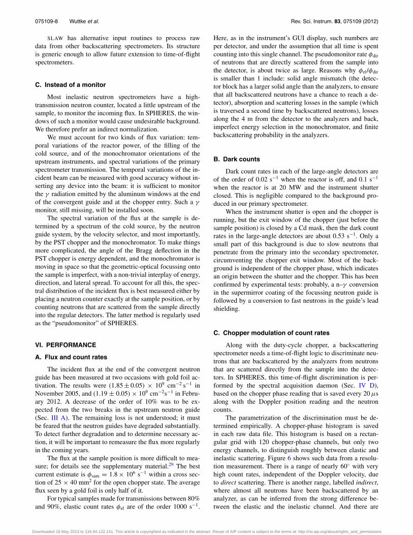
FIG. 7. A resolution measurement with a user-provided sample (a powderof hydrogen-rich organic crystals at 3 K, in a flat cell calculated for 90%transmission). Cumulated data from the six large-angle detectors with thebest signal-to-noise ratio. The solid line is a Gaussian fit to the central region|¯ω| < 0.6 μeV.
D. Resolution and signal-to-noise ratio
The instrumental resolution can be empirically deter-mined by measuring the elastic scattering of a solid. Thescattering should be predominantly incoherent to guaranteesufficient intensity at all scattering angles. Vanadium, the elas-tic incoherent reference scattering par excellence, is not wellsuited because its absorption cross section at λ = 6.27 Å ismore than three times larger than its scattering cross section.Therefore, we prefer a simple plastic foil (Hostaphan RN 250:a polyethylene terephthalate foil of 0.25 mm thickness) as ourreference scatterer.
In most experiments, however, the resolution is measuredon the user sample, cooled to a low temperature where al-most all scattering is elastic. This has the advantage that thesample geometry is exactly the same as in the productionmeasurements.
Figure 7 shows such a resolution spectrum from a userexperiment. The Doppler drive was running with the maxi-mum velocity amplitude of 4.7 m/s, resulting in a dynamicrange of ± 31 μeV. To determine the resolution width andthe elastic amplitude, the centre of the elastic peak (|¯ω|< 0.6 μeV) has been fitted by a Gaussian, which is anexcellent approximation though there are pronounced non-Gaussian wings at larger energy transfers. The fwhm is ob-tained by multiplying the standard deviation of the Gaussianwith
√8 ln(2).
When the Doppler drive is run with small to moderatevelocity amplitudes, the resolution at large scattering anglesis typically between 0.62 and 0.65 μeV. At the maximumDoppler frequency used here, the resolution is slightly re-duced (to 0.66 μeV), probably because of distortions of themonochromator support.
The signal-to-noise ratio (SNR) depends obviously onhow we define the “noise.” If we average only over energiesfar off the central peak, say |¯ω| ≥ 20 μeV, then we obtainin the present example 1750:1. The SNR also depends on thesample: if the sample is too thin, then the sample-independentconstant background contributes relatively more; if the sam-ple is too thick, then many backscattered neutrons are lostwhen they retraverse the sample.
Downloaded 16 May 2013 to 134.94.122.141. This article is copyrighted as indicated in the abstract. Reuse of AIP content is subject to the terms at: http://rsi.aip.org/about/rights_and_permissions
075109-10 Wuttke et al. Rev. Sci. Instrum. 83, 075109 (2012)
TABLE II. Comparison of the three backscattering spectrometers IN16 ofthe ILL,13–15, 44 HFBS at NIST,19 and SPHERES of the JCNS at FRM II.
Instrument IN16a HFBS SPHERES
Reactor power (MW) 58 20 20PG(002) speed (m/s) 75 250 100Si(111) thickness (μm) 700 750 500Resolution fwhm (μeV) 0.8–0.9 0.93 0.62–0.65Flux at sampleb (106 s−1) 1.2 2.4 1.8Rescaled fluxc 0.17 0.91 1Signal-to-noise ratiod 1000e 600 1750
aWith the unpolished, deformed monochromator/analyzer set that is used in almost allexperiments.bWhile chopper open. Au foil activation gives half of this value.cFlux at sample, divided by resolution width and reactor power, arbitrarily normalizedto the value of SPHERES.dBest value reported for a non-absorbing sample of optimum thickness.eNot mentioned in the instrument descriptions,13–15, 44 but confirmed by instrumentusers.
VII. COMPARATIVE STATUS AND PERSPECTIVE
In Table II, some design and performance parametersof the three backscattering spectrometers IN16, HFBS, andSPHERES are compared. These parameters are intercorre-lated as follows.
The instrumental resolution is within 5% proportional tothe chosen thickness of the Si(111) monochromator/analyzerwafers. This confirms the fundamental importance of the crys-tal choice for the instrument performance, and it shows that allthree instruments very closely attain the optimum resolutionallowed by their crystal sets.
Ceteris paribus, the flux at the sample should be propor-tional to the reactor power. In a very good approximation, itshould also be proportional to the width of the energy bandselected by the monochromator. Therefore, the figure of meritthat describes the overall efficiency of the cold source, of theneutron guides, and of the primary spectrometer is flux di-vided by reactor power divided by resolution width. The com-parison of this rescaled flux shows how much the compact de-sign of HFBS and SPHERES, due to Schelten and Alefeld,17
is superior to the double-deflector layout of IN16.The primary spectrometer transmission is also somewhat
related to the signal-to-noise ratio: to maximize the latter, weinstalled in SPHERES ad hoc several slits that cut away some10% of the incoming and of the backscattered beam in orderto prevent neutrons from being transmitted through the closedchopper. The next chopper, currently under construction, willhopefully allow us to take away these slits and to increasethe flux at the sample accordingly. Furthermore, in this newchopper, the PG(002) deflector crystals will be moved withabout optimum speed, which will result in yet another impor-tant gain in flux.
At small scattering angles, analyzers cannot be alignedto exact backscattering geometry because detectors must beplaced outside the incoming neutron beam. This makes theresolution much wider and more assymetric than in the reg-ular backscattering detectors. Supported by simulations, wehave improved the resolution at small angles by breakingthe azimuthal symmetry of the analyzer rings, as will be de-scribed separately.45
ACKNOWLEDGMENTS
Building and commissioning SPHERES has beenfunded by the German Bundesministerium für Bildung undForschung (Project Nos. 05NX8CJ1 and 03RI16JU1). Foun-dations for SPHERES were laid by former project scientistsOliver Kirstein and Peter Rottländer, and by former projectengineer Tadeusz Kozielewski. Many other colleagues fromthe Forschungszentrum Jülich contributed to this project. Wewould like to acknowledge Ulrich Probst, Helga Straatmann,and Thomas Koppitz for the development of the chopperrotor, Ulrich Giesen and Ulrich Pabst for a vibrational anal-ysis thereof, Christoph Tiemann for his contribution to theDoppler drive, Gerd Schaffrath for the instrument housing,Manfred Bednarek for the electrical installations, PeterStronciwilk and Marco Gödel for mechanical constructions,Vu Thanh Nguyen for the accurate gluing of the siliconcrystals, Harald Kusche, Andreas Nebel, and Björn Poschenfor technical support, and Alexander Ioffe for coordinat-ing the JCNS outstation at FRM II. Sergej Manoshin andAlexander Ioffe contributed a simulation of the convergentneutron guide. Michaela Zamponi, the new instrument re-sponsible since fall 2011, contributed to the last Au activationmeasurement.
We are grateful to Winfried Petry, Jürgen Neuhaus, andall the staff of FRM II for their hospitality. We thank HaraldTürck for generous help at all levels of engineering, Chris-tian Breunig for the neutron guide, Philipp Jüttner for theshutter construction, Helmut Zeising, Birgit Wierczinski, andtheir entire team for the smooth handling of the radiopro-tection necessities, and Ralf Lorenz for sensibly supervisingour safety. We thank our colleagues and friendly concurrentsBernhard Frick, Tilo Seydel, and Lambert van Eijck of theILL for stimulating discussions and the open exchange of ex-periences and ideas. Victoria García Sakai, Goran Gasparovic,and Dan A. Neumann kindly showed us HFBS at NIST, andAndreas Meyer provided insights from his commissioningexperience.
1M. Bée, Quasielastic Neutron Scattering (Adam Hilger, Bristol, 1988).2R. Hempelmann, Quasielastic Neutron Scattering and Solid State Diffusion(Clarendon, Oxford, 2000).
3H. Maier-Leibnitz, Nukleonik 8, 61 (1966).4B. Alefeld, M. Birr, and A. Heidemann, Naturwiss. 56, 410 (1969).5B. Alefeld, Kerntechnik 14, 15 (1972).6G. Allen, R. E. Ghosh, A. Heidemann, J. Higgins, and W. S. Howells,Chem. Phys. Lett. 27, 308 (1974).
7J. C. Cook, W. Petry, A. Heidemann, and J. F. Barthélemy, Nucl. Instrum.Methods Phys. Res. A 312, 553 (1992).
8O. G. Randl, H. Franz, T. Gerstendörfer, W. Petry, G. Vogl, and A. Magerl,Physica B 234–236, 1064 (1997).
9A. Heidemann, I. Anderson, M. Prager, and W. Press, Z. Phys. B 51, 319(1983).
10T. Springer, Philos. Trans. R. Soc. London, Ser. B 290, 673 (1980).11B. Alefeld, T. Springer, and A. Heidemann, Nucl. Sci. Eng. 110, 84
(1992).12A. J. Dianoux, Physica B 182, 389 (1992).13B. Frick, A. Magerl, Y. Blanc, and R. Rebesco, Physica B 234–236, 1177
(1997).14B. Frick and M. Gonzalez, Physica B 301, 8 (2001).15B. Frick, Neutron News 13, 15 (2002).16N. de Souza et al., Emu project, see http://www.ansto.gov.
au/research/bragg_institute/facilities/instruments/emu_-_high-resolution_backscattering_spectrometer.
Downloaded 16 May 2013 to 134.94.122.141. This article is copyrighted as indicated in the abstract. Reuse of AIP content is subject to the terms at: http://rsi.aip.org/about/rights_and_permissions
075109-11 Wuttke et al. Rev. Sci. Instrum. 83, 075109 (2012)
17J. Schelten and B. Alefeld, in Proceedings of the Workshop on NeutronScattering Instrumentation for the SNQ, Maria Laach, 3-5 September 1984,edited by R. Scherm and H. Stiller (Berichte der KernforschungsanlageJülich, Jül-1954) (KFA, Jülich, 1984).
18P. M. Gehring and D. A. Neumann, Physica B 241–243, 64 (1998).19A. Meyer, R. M. Dimeo, P. M. Gehring, and D. A. Neumann, Rev. Sci.
Instrum. 74, 2759 (2003).20M. A. Gonzalez and B. Frick, Appl. Phys. A 74s1, 474 (2002).21B. Frick, H. N. Bordallo, T. Seydel, J.-F. Barthélémy, M. Thomas,
D. Bazzoli, and H. Schober, Physica B 385–386, 1101 (2006).22O. Kirstein, M. Prager, H. Grimm, and D. Richter, J. Neutron Res. 8, 119
(1999).23O. Kirstein, M. Prager, T. Kozielewski, and D. Richter, Physica B 283, 361
(2000).24O. Kirstein, T. Kozielewski, M. Prager, and D. Richter, Physica B 291, 310
(2000).25O. Kirstein, T. Kozielewski, and M. Prager, in Proceedings of the Deutsche
Neutronenstreutagung 2001, edited by T. Brückel (Materie und Material,Vol. 8), FZ Jülich, Jülich (2001).
26O. Kirstein, T. Kozielewski, M. Prager, and D. Richter, Appl. Phys. A 74,S133 (2002).
27P. Rottländer, T. Kozielewski, M. Prager, and D. Richter, Physica B 350,e823 (2004).
28SPHERES shares the guide NL6a with the monochromator of MIRA 2(3–6 Å). The alternate setup MIRA 1 uses an end position at the heavilycurved guide NL6b (radius 84 m) to obtain very cold neutrons (8–30 Å).
29See supplementary material at http://dx.doi.org/10.1063/1.4732806 formore details on instrument components (suppliers, neutron guides, argonfilling), on the diffraction data acquisition, and on the estimation of fluxand count rates.
30A. Meyer, J. Wuttke, W. Petry, A. Peker, R. Bormann, G. Coddens,L. Kranich, O. G. Randl, and H. Schober, Phys. Rev. B 53, 12107(1996).
31A. V. Skripov, J. C. Cook, D. S. Sibirtsev, C. Karmonik, and R. Hempel-mann, J. Phys. Condens. Matter 10, 1787 (1998).
32M. Hennig, B. Frick, and T. Seydel, J. Appl. Crystallogr. 44, 467(2011).
33J. Wuttke, “Theory of Bragg reflection by moving crystals and optimisationof a phase-space transform chopper,” Rev. Sci. Instrum. (to be published).
34U. Probst, H. Kämmerling, T. Kozielewski, H. Straatmann, P. Rottländer,and T. Koppitz, European patent (EP) application 1706876 (2005).
35A. D. Stoica and M. Popovici, J. Appl. Crystallogr. 22, 448 (1989).36J. Combet, B. Frick, O. Losserand, M. Gamnon, and B. Gurard, Physica B
283, 380 (2000).37A. Gohr et al., Dokuwiki, see http://www.dokuwiki.org/ (2004–2011).38M. Drochner, H. Kleines, M. Kirsch, T. Kozielewski, M. Prager, and
P. Rottländer, in Proceedings of the 14th IEE-NPSS Real Time Conference,Stockholm, 2005.
39J. Wuttke, lmfit - a C/C++ routine for Levenberg-Marquardt mini-mization with wrapper for least-squares curve fitting, based on workby B. S. Garbow, K. E. Hillstrom, J. J. Moré, and S. Moshier, seehttp://joachimwuttke.de/lmfit.
40O. Ben-Kiki, C. Evans, and I. döt Net, see http://www.yaml.org for “YAMLain’t markup language.”
41H. Kleines, F. Suxdorf, M. Drochner, P. Rottländer, M. Prager,T. Kozielewski, and A. Budwig, in Proceedings of the KEK, 2005–18,WEP25 (2005).
42J. Wuttke, SLAW: Neutron scattering histograms to scattering law con-verter, http://apps.jcns.fz-juelich.de/slaw.
43J. Wuttke, absco: absorption corrections for x-ray and neutron diffraction,http://apps.jcns.fz-juelich.de/absco.
44See http://www.ill.eu/instruments-support/instruments-groups/instruments/in16/characteristics/ for IN16 characteristics.
45J. Wuttke, “Optimization of Small-Angle Geometry in the NeutronBackscattering Spectrometer SPHERES,” Rev. Sci. Instrum. (to bepublished).
Downloaded 16 May 2013 to 134.94.122.141. This article is copyrighted as indicated in the abstract. Reuse of AIP content is subject to the terms at: http://rsi.aip.org/about/rights_and_permissions


![[Chu] Backscattering Spectrometry](https://img.pdfslide.us/doc/110x75/553e2752550346b9308b4919/chu-backscattering-spectrometry.jpg)