Embed Size (px)
Citation preview
Revision: A 5/16/2014
Sheet 1 of 15 ©2014 Knowles Electronics
SPH0641LU4H-1
Digital Zero-Height SiSonicTM Microphone
With Multi-Mode And Ultrasonic Support
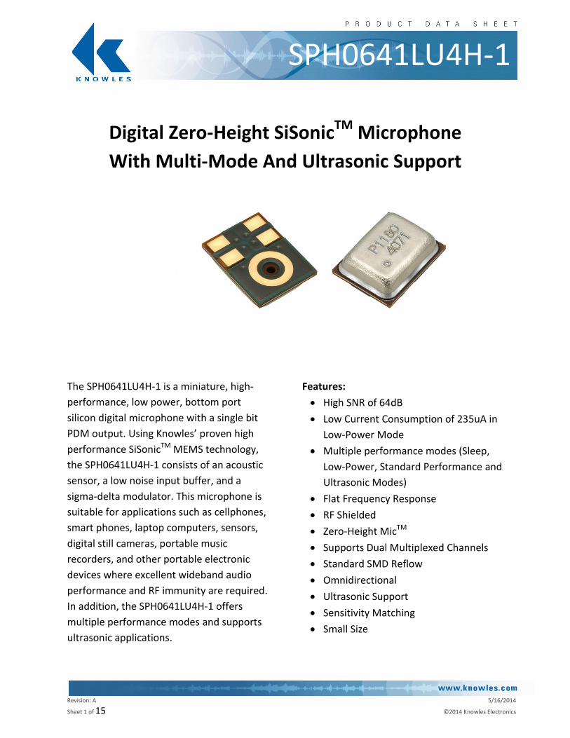
The SPH0641LU4H-1 is a miniature, high-
performance, low power, bottom port
silicon digital microphone with a single bit
PDM output. Using Knowles’ proven high
performance SiSonicTM MEMS technology,
the SPH0641LU4H-1 consists of an acoustic
sensor, a low noise input buffer, and a
sigma-delta modulator. This microphone is
suitable for applications such as cellphones,
smart phones, laptop computers, sensors,
digital still cameras, portable music
recorders, and other portable electronic
devices where excellent wideband audio
performance and RF immunity are required.
In addition, the SPH0641LU4H-1 offers
multiple performance modes and supports
ultrasonic applications.
Features:
High SNR of 64dB
Low Current Consumption of 235uA in
Low-Power Mode
Multiple performance modes (Sleep,
Low-Power, Standard Performance and
Ultrasonic Modes)
Flat Frequency Response
RF Shielded
Zero-Height MicTM
Supports Dual Multiplexed Channels
Standard SMD Reflow
Omnidirectional
Ultrasonic Support
Sensitivity Matching
Small Size
Revision: A 5/16/2014
Sheet 2 of 15 ©2014 Knowles Electronics
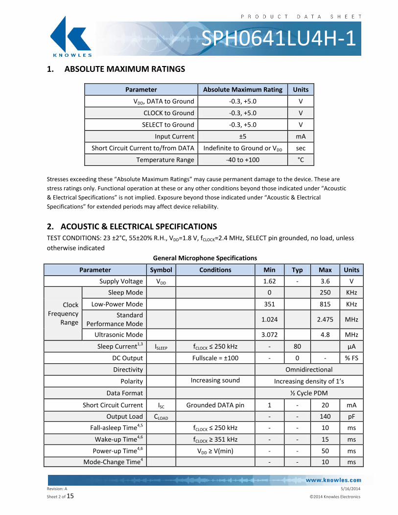
SPH0641LU4H-1 1. ABSOLUTE MAXIMUM RATINGS
Parameter Absolute Maximum Rating Units
VDD, DATA to Ground -0.3, +5.0 V
CLOCK to Ground -0.3, +5.0 V
SELECT to Ground -0.3, +5.0 V
Input Current ±5 mA
Short Circuit Current to/from DATA Indefinite to Ground or VDD sec
Temperature Range -40 to +100 °C
Stresses exceeding these “Absolute Maximum Ratings” may cause permanent damage to the device. These are
stress ratings only. Functional operation at these or any other conditions beyond those indicated under “Acoustic
& Electrical Specifications” is not implied. Exposure beyond those indicated under “Acoustic & Electrical
Specifications” for extended periods may affect device reliability.
2. ACOUSTIC & ELECTRICAL SPECIFICATIONS TEST CONDITIONS: 23 ±2°C, 55±20% R.H., VDD=1.8 V, fCLOCK=2.4 MHz, SELECT pin grounded, no load, unless
otherwise indicated
General Microphone Specifications
Parameter Symbol Conditions Min Typ Max Units
Supply Voltage VDD 1.62 - 3.6 V
Clock Frequency
Range
Sleep Mode
0
250 KHz
Low-Power Mode
351
815 KHz
Standard Performance Mode
1.024
2.475 MHz
Ultrasonic Mode
3.072
4.8 MHz
Sleep Current1,3 ISLEEP fCLOCK ≤ 250 kHz - 80
µA
DC Output
Fullscale = ±100 - 0 - % FS
Directivity
Omnidirectional
Polarity
Increasing sound pressure
Increasing density of 1’s
Data Format
½ Cycle PDM
Short Circuit Current ISC Grounded DATA pin 1 - 20 mA
Output Load CLOAD - - 140 pF
Fall-asleep Time4,5
fCLOCK ≤ 250 kHz - - 10 ms
Wake-up Time4,6
fCLOCK ≥ 351 kHz - - 15 ms
Power-up Time4,6 VDD ≥ V(min) - - 50 ms
Mode-Change Time4 - - 10 ms
Revision: A 5/16/2014
Sheet 3 of 15 ©2014 Knowles Electronics
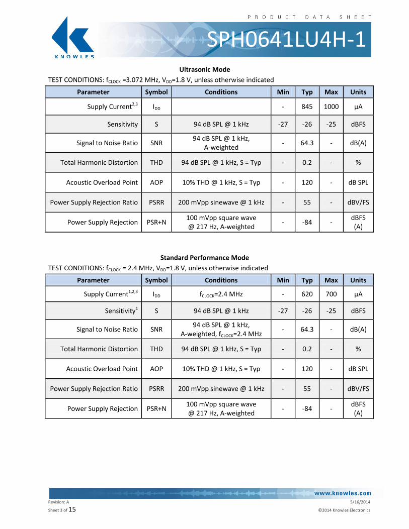
SPH0641LU4H-1 Ultrasonic Mode
TEST CONDITIONS: fCLOCK =3.072 MHz, VDD=1.8 V, unless otherwise indicated
Parameter Symbol Conditions Min Typ Max Units
Supply Current2,3 IDD - 845 1000 µA
Sensitivity S 94 dB SPL @ 1 kHz -27 -26 -25 dBFS
Signal to Noise Ratio SNR 94 dB SPL @ 1 kHz,
A-weighted - 64.3 - dB(A)
Total Harmonic Distortion THD 94 dB SPL @ 1 kHz, S = Typ - 0.2 - %
Acoustic Overload Point AOP 10% THD @ 1 kHz, S = Typ - 120 - dB SPL
Power Supply Rejection Ratio PSRR 200 mVpp sinewave @ 1 kHz - 55 - dBV/FS
Power Supply Rejection PSR+N 100 mVpp square wave @ 217 Hz, A-weighted
- -84 - dBFS (A)
Standard Performance Mode
TEST CONDITIONS: fCLOCK = 2.4 MHz, VDD=1.8 V, unless otherwise indicated
Parameter Symbol Conditions Min Typ Max Units
Supply Current1,2,3 IDD fCLOCK=2.4 MHz - 620 700 µA
Sensitivity1 S 94 dB SPL @ 1 kHz -27 -26 -25 dBFS
Signal to Noise Ratio SNR 94 dB SPL @ 1 kHz,
A-weighted, fCLOCK=2.4 MHz - 64.3 - dB(A)
Total Harmonic Distortion THD 94 dB SPL @ 1 kHz, S = Typ - 0.2 - %
Acoustic Overload Point AOP 10% THD @ 1 kHz, S = Typ - 120 - dB SPL
Power Supply Rejection Ratio PSRR 200 mVpp sinewave @ 1 kHz - 55 - dBV/FS
Power Supply Rejection PSR+N 100 mVpp square wave @ 217 Hz, A-weighted
- -84 - dBFS (A)
Revision: A 5/16/2014
Sheet 4 of 15 ©2014 Knowles Electronics
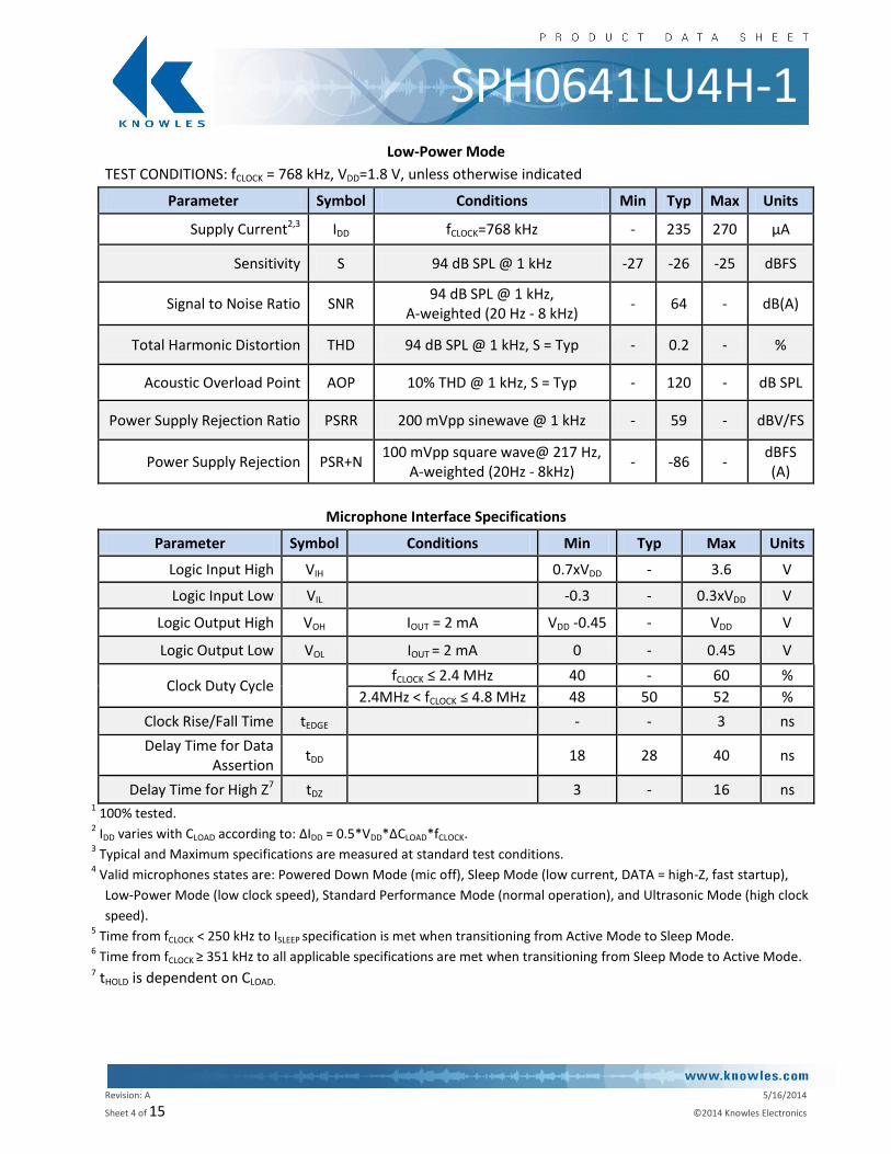
SPH0641LU4H-1 Low-Power Mode
TEST CONDITIONS: fCLOCK = 768 kHz, VDD=1.8 V, unless otherwise indicated
Parameter Symbol Conditions Min Typ Max Units
Supply Current2,3 IDD fCLOCK=768 kHz - 235 270 µA
Sensitivity S 94 dB SPL @ 1 kHz -27 -26 -25 dBFS
Signal to Noise Ratio SNR 94 dB SPL @ 1 kHz,
A-weighted (20 Hz - 8 kHz) - 64 - dB(A)
Total Harmonic Distortion THD 94 dB SPL @ 1 kHz, S = Typ - 0.2 - %
Acoustic Overload Point AOP 10% THD @ 1 kHz, S = Typ - 120 - dB SPL
Power Supply Rejection Ratio PSRR 200 mVpp sinewave @ 1 kHz - 59 - dBV/FS
Power Supply Rejection PSR+N 100 mVpp square wave@ 217 Hz,
A-weighted (20Hz - 8kHz) - -86 -
dBFS (A)
Microphone Interface Specifications
Parameter Symbol Conditions Min Typ Max Units
Logic Input High VIH 0.7xVDD - 3.6 V
Logic Input Low VIL -0.3 - 0.3xVDD V
Logic Output High VOH IOUT = 2 mA VDD -0.45 - VDD V
Logic Output Low VOL IOUT = 2 mA 0 - 0.45 V
Clock Duty Cycle
fCLOCK ≤ 2.4 MHz 40 - 60 %
2.4MHz < fCLOCK ≤ 4.8 MHz 48 50 52 %
Clock Rise/Fall Time tEDGE - - 3 ns
Delay Time for Data Assertion
tDD 18 28 40 ns
Delay Time for High Z7 tDZ 3 - 16 ns 1 100% tested.
2 IDD varies with CLOAD according to: ΔIDD = 0.5*VDD*ΔCLOAD*fCLOCK.
3 Typical and Maximum specifications are measured at standard test conditions.
4 Valid microphones states are: Powered Down Mode (mic off), Sleep Mode (low current, DATA = high-Z, fast startup),
Low-Power Mode (low clock speed), Standard Performance Mode (normal operation), and Ultrasonic Mode (high clock
speed). 5 Time from fCLOCK < 250 kHz to ISLEEP specification is met when transitioning from Active Mode to Sleep Mode.
6 Time from fCLOCK ≥ 351 kHz to all applicable specifications are met when transitioning from Sleep Mode to Active Mode.
7 tHOLD is dependent on CLOAD.
Revision: A 5/16/2014
Sheet 5 of 15 ©2014 Knowles Electronics
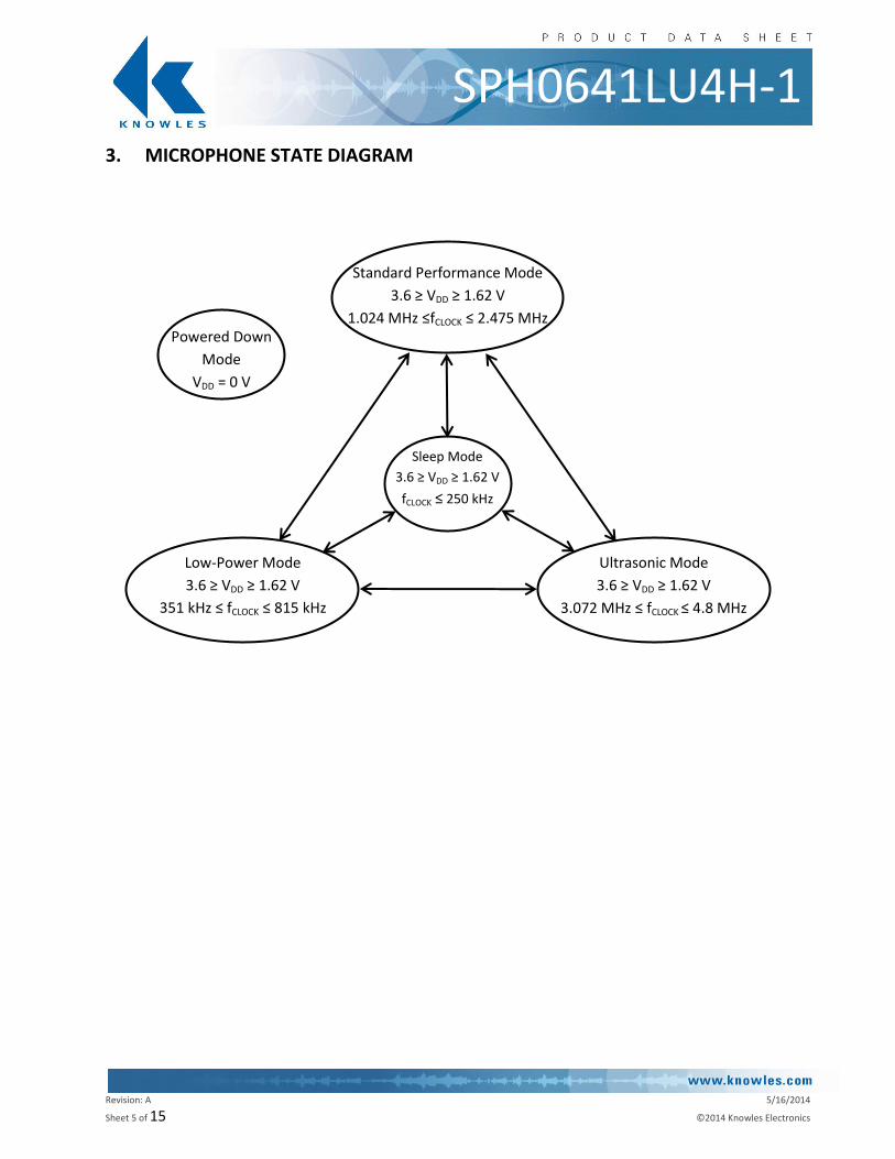
SPH0641LU4H-1 3. MICROPHONE STATE DIAGRAM
Standard Performance Mode
3.6 ≥ VDD ≥ 1.62 V
1.024 MHz ≤fCLOCK ≤ 2.475 MHz
Sleep Mode
3.6 ≥ VDD ≥ 1.62 V
fCLOCK ≤ 250 kHz
Ultrasonic Mode
3.6 ≥ VDD ≥ 1.62 V
3.072 MHz ≤ fCLOCK ≤ 4.8 MHz
Low-Power Mode
3.6 ≥ VDD ≥ 1.62 V
351 kHz ≤ fCLOCK ≤ 815 kHz
Powered Down
Mode
VDD = 0 V
Revision: A 5/16/2014
Sheet 6 of 15 ©2014 Knowles Electronics
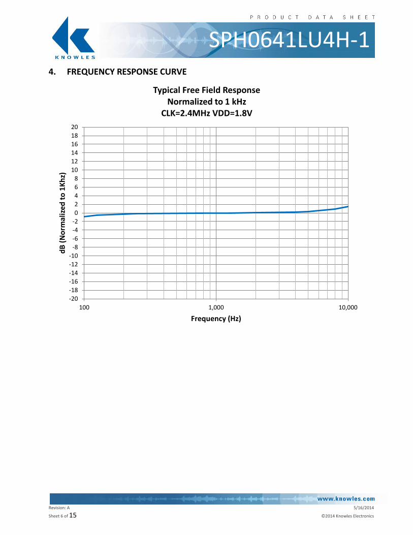
SPH0641LU4H-1 4. FREQUENCY RESPONSE CURVE
-20
-18
-16
-14
-12
-10
-8
-6
-4
-2
0
2
4
6
8
10
12
14
16
18
20
100 1,000 10,000
dB
(N
orm
aliz
ed t
o 1
Kh
z)
Frequency (Hz)
Typical Free Field Response Normalized to 1 kHz
CLK=2.4MHz VDD=1.8V
Revision: A 5/16/2014
Sheet 7 of 15 ©2014 Knowles Electronics
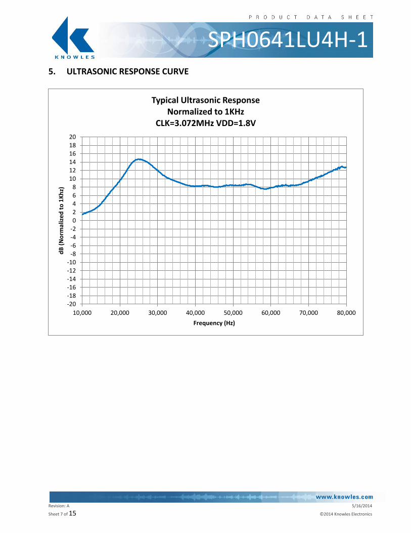
SPH0641LU4H-1 5. ULTRASONIC RESPONSE CURVE
-20-18-16-14-12-10
-8-6-4-202468
101214161820
10,000 20,000 30,000 40,000 50,000 60,000 70,000 80,000
dB
(N
orm
aliz
ed
to
1K
hz)
Frequency (Hz)
Typical Ultrasonic Response Normalized to 1KHz
CLK=3.072MHz VDD=1.8V
Revision: A 5/16/2014
Sheet 8 of 15 ©2014 Knowles Electronics
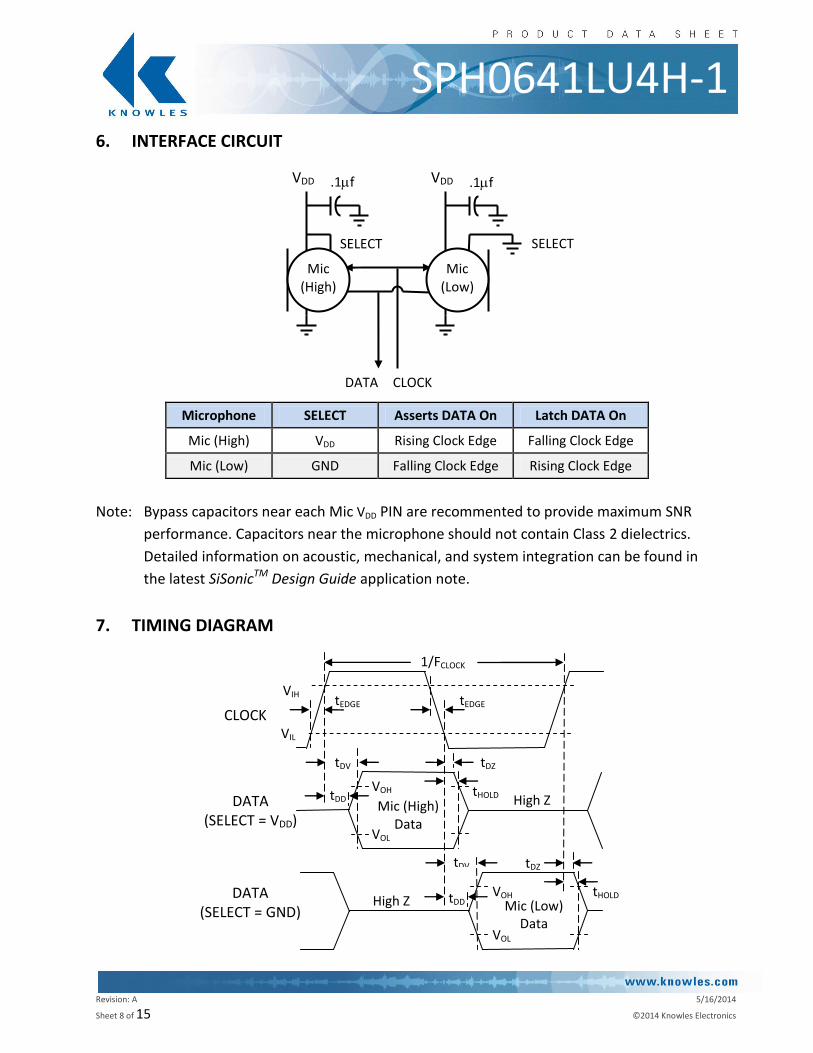
SPH0641LU4H-1 6. INTERFACE CIRCUIT
Microphone SELECT Asserts DATA On Latch DATA On
Mic (High) VDD Rising Clock Edge Falling Clock Edge
Mic (Low) GND Falling Clock Edge Rising Clock Edge
Note: Bypass capacitors near each Mic VDD PIN are recommented to provide maximum SNR
performance. Capacitors near the microphone should not contain Class 2 dielectrics.
Detailed information on acoustic, mechanical, and system integration can be found in
the latest SiSonicTM Design Guide application note.
7. TIMING DIAGRAM
VDD VDD
SELECT
Mic (High)
DATA CLOCK
.1f .1f
Mic (Low)
SELECT
tEDGE
DATA (SELECT = VDD)
tDD
tDV tDZ
CLOCK
DATA (SELECT = GND)
VIH
VIL
tDV tDZ
High Z Mic (Low) Data
High Z Mic (High) Data
VOH
VOL
tEDGE
VOH
VOL
1/FCLOCK
tDD tHOLD
tHOLD
Revision: A 5/16/2014
Sheet 9 of 15 ©2014 Knowles Electronics
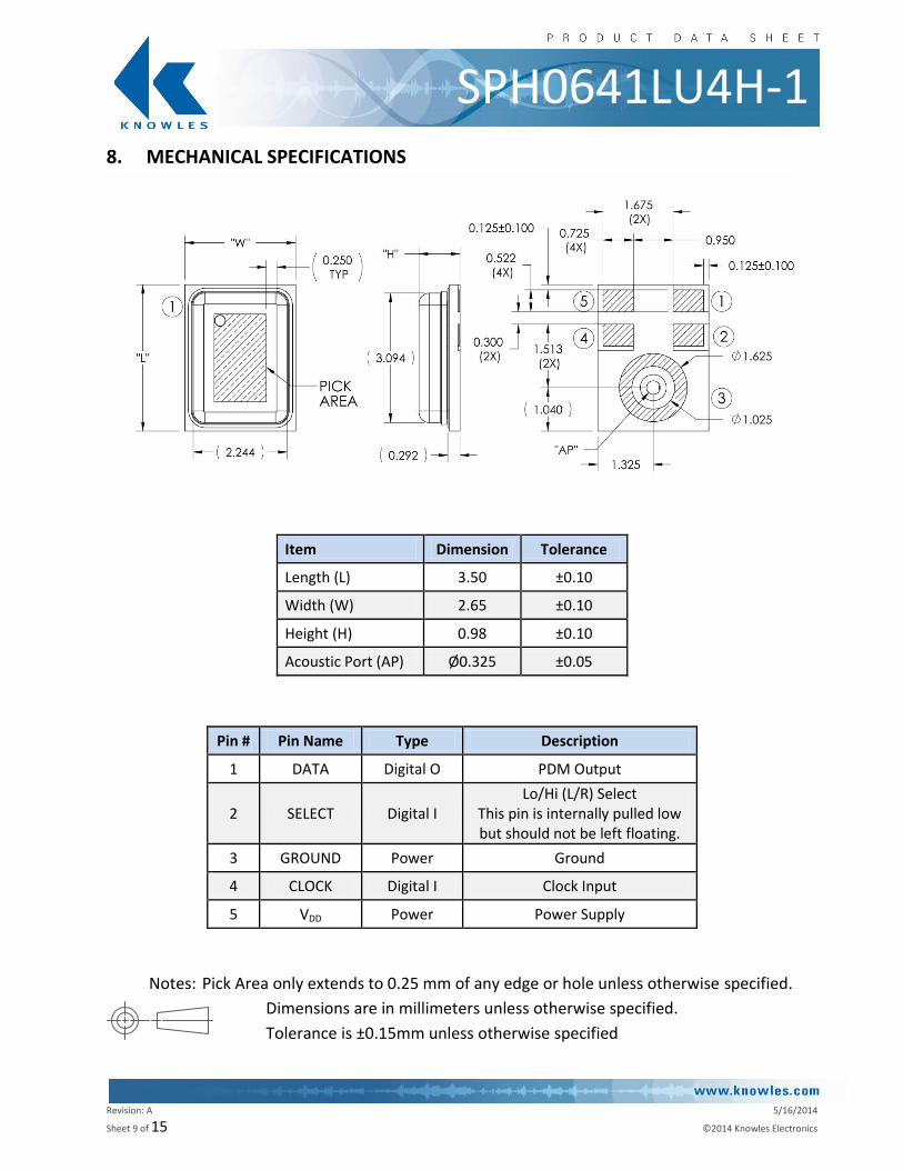
SPH0641LU4H-1 8. MECHANICAL SPECIFICATIONS
Item Dimension Tolerance
Length (L) 3.50 ±0.10
Width (W) 2.65 ±0.10
Height (H) 0.98 ±0.10
Acoustic Port (AP) Ø0.325 ±0.05
Pin # Pin Name Type Description
1 DATA Digital O PDM Output
2 SELECT Digital I Lo/Hi (L/R) Select
This pin is internally pulled low but should not be left floating.
3 GROUND Power Ground
4 CLOCK Digital I Clock Input
5 VDD Power Power Supply
Notes: Pick Area only extends to 0.25 mm of any edge or hole unless otherwise specified.
Dimensions are in millimeters unless otherwise specified.
Tolerance is ±0.15mm unless otherwise specified
Revision: A 5/16/2014
Sheet 10 of 15 ©2014 Knowles Electronics
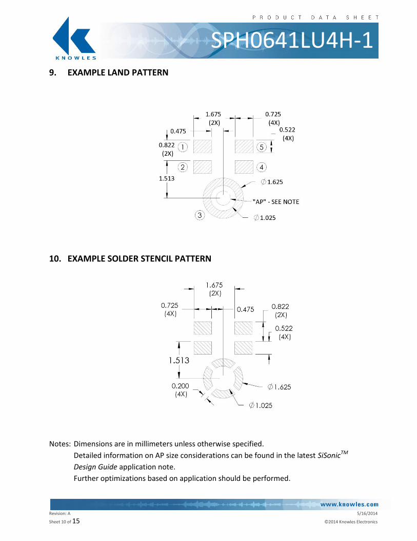
SPH0641LU4H-1 9. EXAMPLE LAND PATTERN
10. EXAMPLE SOLDER STENCIL PATTERN
Notes: Dimensions are in millimeters unless otherwise specified.
Detailed information on AP size considerations can be found in the latest SiSonicTM
Design Guide application note.
Further optimizations based on application should be performed.
Revision: A 5/16/2014
Sheet 11 of 15 ©2014 Knowles Electronics
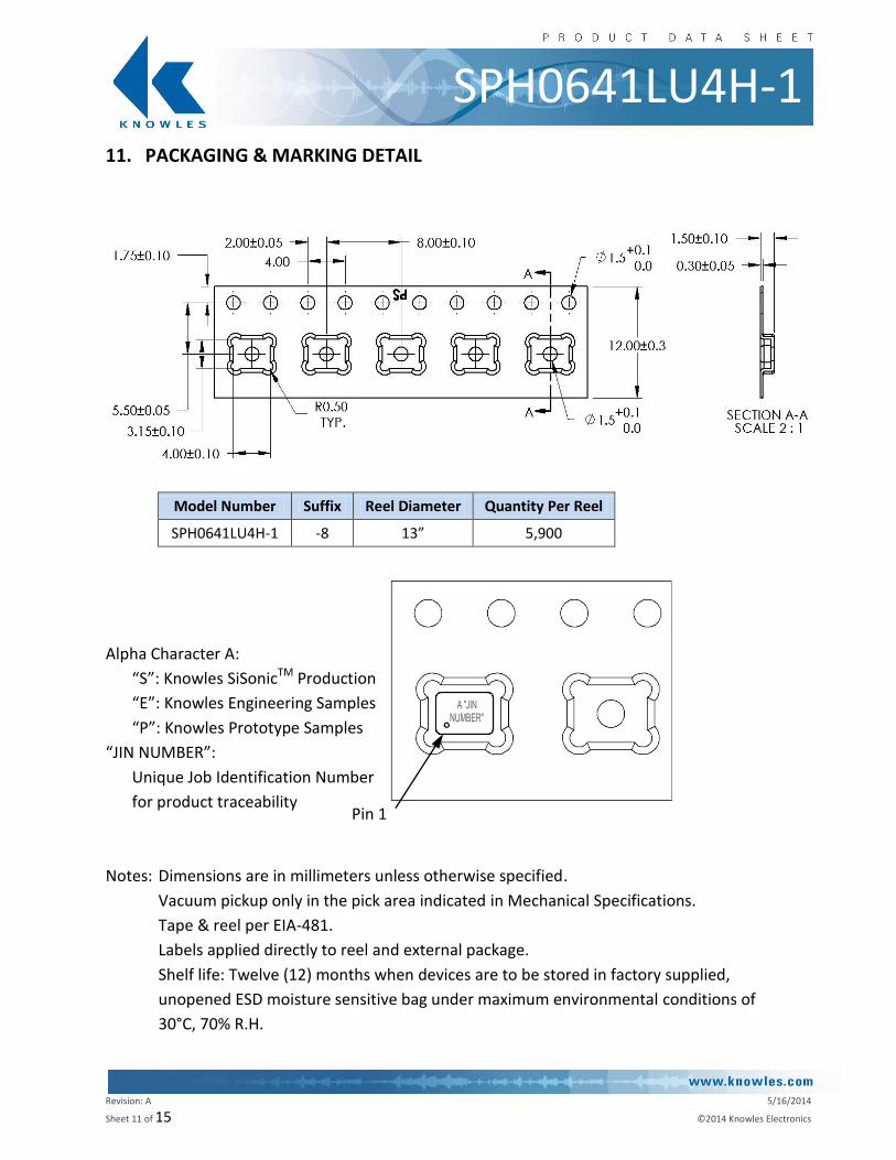
SPH0641LU4H-1 11. PACKAGING & MARKING DETAIL
Model Number Suffix Reel Diameter Quantity Per Reel
SPH0641LU4H-1 -8 13” 5,900
Alpha Character A:
“S”: Knowles SiSonicTM Production
“E”: Knowles Engineering Samples
“P”: Knowles Prototype Samples
“JIN NUMBER”:
Unique Job Identification Number
for product traceability
Notes: Dimensions are in millimeters unless otherwise specified.
Vacuum pickup only in the pick area indicated in Mechanical Specifications.
Tape & reel per EIA-481.
Labels applied directly to reel and external package.
Shelf life: Twelve (12) months when devices are to be stored in factory supplied,
unopened ESD moisture sensitive bag under maximum environmental conditions of
30°C, 70% R.H.
Pin 1
Revision: A 5/16/2014
Sheet 12 of 15 ©2014 Knowles Electronics
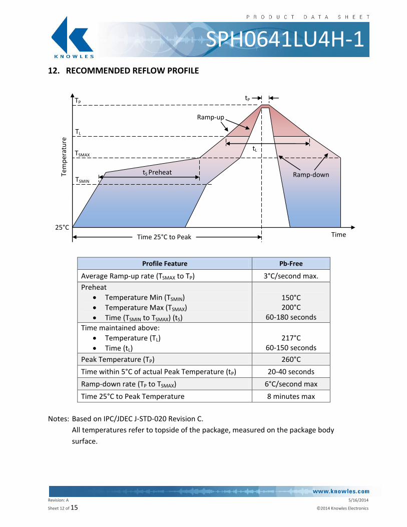
SPH0641LU4H-1 12. RECOMMENDED REFLOW PROFILE
Profile Feature Pb-Free
Average Ramp-up rate (TSMAX to TP) 3°C/second max.
Preheat
Temperature Min (TSMIN)
Temperature Max (TSMAX)
Time (TSMIN to TSMAX) (tS)
150°C 200°C
60-180 seconds
Time maintained above:
Temperature (TL)
Time (tL)
217°C
60-150 seconds
Peak Temperature (TP) 260°C
Time within 5°C of actual Peak Temperature (tP) 20-40 seconds
Ramp-down rate (TP to TSMAX) 6°C/second max
Time 25°C to Peak Temperature 8 minutes max
Notes: Based on IPC/JDEC J-STD-020 Revision C.
All temperatures refer to topside of the package, measured on the package body
surface.
Tem
per
atu
re
Time 25°C to Peak
Ramp-down
Ramp-up
TSMIN
TSMAX
TL
TP
tL
tP
tS Preheat
Time 25°C
Revision: A 5/16/2014
Sheet 13 of 15 ©2014 Knowles Electronics
SPH0641LU4H-1 13. ADDITIONAL NOTES
(A) MSL (moisture sensitivity level) Class 1.
(B) Maximum of 3 reflow cycles is recommended.
(C) In order to minimize device damage:
Do not board wash or clean after the reflow process.
Do not brush board with or without solvents after the reflow process.
Do not directly expose to ultrasonic processing, welding, or cleaning.
Do not insert any object in port hole of device at any time.
Do not apply over 30 psi of air pressure into the port hole.
Do not pull a vacuum over port hole of the microphone.
Do not apply a vacuum when repacking into sealed bags at a rate faster than 0.5 atm/sec.
14. MATERIALS STATEMENT
Meets the requirements of the European RoHS directive 2011/65/EC as amended.
Meets the requirements of the industry standard IEC 61249-2-21:2003 for halogenated
substances and Knowles Green Materials Standards Policy section on Halogen-Free.
Ozone depleting substances are not used in the product or the processes used to make the
product, including compounds listed in Annex A, B, and C of the “Montreal Protocol on
Substances That Deplete the Ozone Layer.”
Revision: A 5/16/2014
Sheet 14 of 15 ©2014 Knowles Electronics
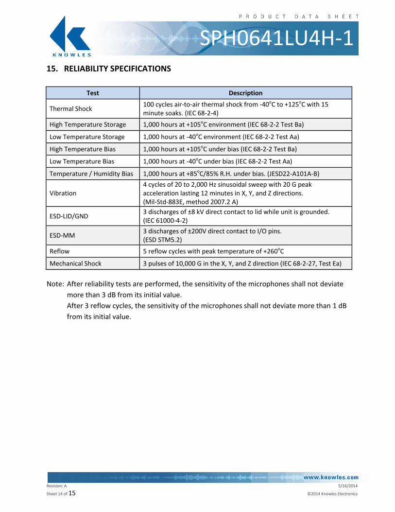
SPH0641LU4H-1 15. RELIABILITY SPECIFICATIONS
Test Description
Thermal Shock 100 cycles air-to-air thermal shock from -40oC to +125oC with 15 minute soaks. (IEC 68-2-4)
High Temperature Storage 1,000 hours at +105oC environment (IEC 68-2-2 Test Ba)
Low Temperature Storage 1,000 hours at -40oC environment (IEC 68-2-2 Test Aa)
High Temperature Bias 1,000 hours at +105oC under bias (IEC 68-2-2 Test Ba)
Low Temperature Bias 1,000 hours at -40oC under bias (IEC 68-2-2 Test Aa)
Temperature / Humidity Bias 1,000 hours at +85oC/85% R.H. under bias. (JESD22-A101A-B)
Vibration 4 cycles of 20 to 2,000 Hz sinusoidal sweep with 20 G peak acceleration lasting 12 minutes in X, Y, and Z directions. (Mil-Std-883E, method 2007.2 A)
ESD-LID/GND 3 discharges of ±8 kV direct contact to lid while unit is grounded. (IEC 61000-4-2)
ESD-MM 3 discharges of ±200V direct contact to I/O pins. (ESD STM5.2)
Reflow 5 reflow cycles with peak temperature of +260oC
Mechanical Shock 3 pulses of 10,000 G in the X, Y, and Z direction (IEC 68-2-27, Test Ea)
Note: After reliability tests are performed, the sensitivity of the microphones shall not deviate
more than 3 dB from its initial value.
After 3 reflow cycles, the sensitivity of the microphones shall not deviate more than 1 dB
from its initial value.
Revision: A 5/16/2014
Sheet 15 of 15 ©2014 Knowles Electronics
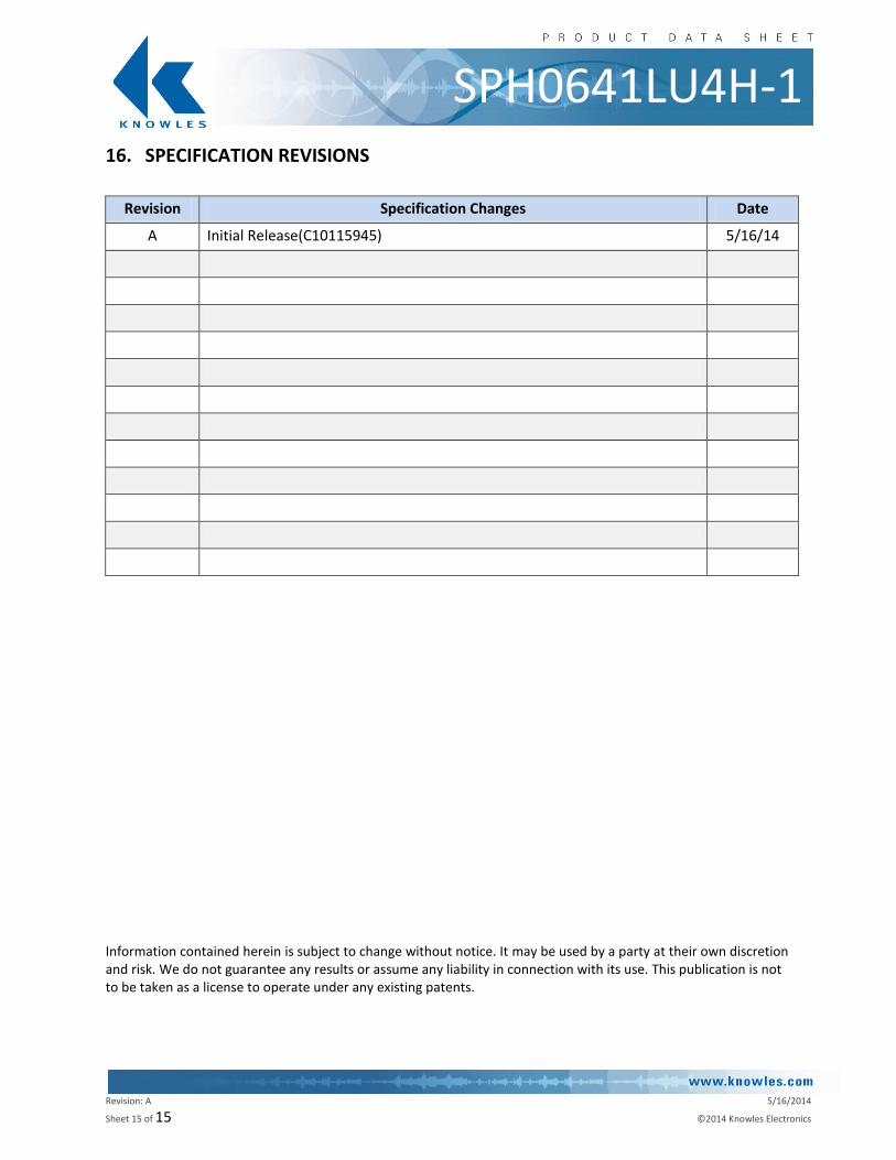
SPH0641LU4H-1 16. SPECIFICATION REVISIONS
Revision Specification Changes Date
A Initial Release(C10115945) 5/16/14
Information contained herein is subject to change without notice. It may be used by a party at their own discretion and risk. We do not guarantee any results or assume any liability in connection with its use. This publication is not to be taken as a license to operate under any existing patents.


![B Recommended land pattern: [mm] D Absolute Maximum](https://img.pdfslide.us/doc/110x75/61edff0d9a309d37b5045ddc/b-recommended-land-pattern-mm-d-absolute-maximum-.jpg)