Embed Size (px)
Citation preview
1919
S U P E R I O RA SHERWOOD COMPANY SWD0215 ©2015 Sherwood Valve, LLC www.sherwoodvalve.com • 888.508.2583MADE IN USA
SUPERIOR HVACR PRODUCTS
Pressure-Relief ValvesDual Pressure-Relief Valve Assembly
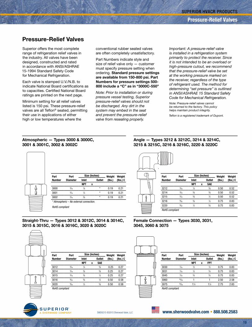
Atmospheric — Types 3000 & 3000C, 3001 & 3001C, 3002 & 3002C
Straight-Thru — Types 3012 & 3012C, 3014 & 3014C, 3015 & 3015C, 3016 & 3016C, 3020 & 3020C
Pressure-Relief Valves
Superior offers the most complete range of refrigeration relief valves in the industry. All valves have been designed, constructed and rated in accordance with ANSI/ASHRAE 15-1994 Standard Safety Code for Mechanical Refrigeration.
Each valve is stamped U.V./N.B. to indicate National Board certifications as to capacities. Certified National Board ratings are printed on the next page.
Minimum setting for all relief valves listed is 150 psi. These pressure-relief valves are all Teflon® seated, permitting their use in applications of either high or low temperatures where the
conventional rubber seated valves are often completely unsatisfactory.
Part Numbers indicate style and size of relief valve only — customer must specify pressure setting when ordering. Standard pressure settings are available from 150-800 psi. Part Numbers for pressure settings 500-800 include a “C” as in “3000C-550”
Note: Prior to installation or during pressure vessel testing, Superior pressure-relief valves should not be discharged. Any dirt in the system may embed in the seat and prevent the pressure-relief valve from resealing properly.
Important: A pressure-relief valve is installed in a refrigeration system primarily to protect the receiver. Since it is not intended to be an overload or high-pressure cutout, we recommend that the pressure-relief valve be set at the working pressure marked on the receiver, regardless of the type of refrigerant used. The method for determining “set pressure” is outlined in ANSI/ASHRAE 15 Standard Safety Code for Mechanical Refrigeration.Note: Pressure-relief valves cannot be returned to the factory. This policy helps maintain product integrity.
Teflon is a registered trademark of Dupont.
Part Number
Port Diameter
Size (Inches) Weight (lbs.)
Weight (lbs.) CInlet Outlet
NPT x3000 3⁄16
1⁄8 * 0.19 0.21
3001 3⁄161⁄4 * 0.19 0.21
3002 3⁄163⁄8 * 0.19 0.21
* Atmospheric – No external connection.
RoHS compliant
Part Number
Port Diameter
Size (Inches) Weight (lbs.)
Weight (lbs.) CInlet Outlet
NPT x SAE3212 3⁄16
1⁄4 3⁄8 0.50 0.52
3214 3⁄163⁄8 3⁄8 0.50 0.52
3215 3⁄163⁄8 1⁄2 0.50 0.52
3216 9⁄323⁄8 1⁄2 0.75 0.83
3220 9⁄321⁄2 5⁄8 0.75 0.83
RoHS compliant
Part Number
Port Diameter
Size (Inches) Weight (lbs.)
Weight (lbs.) CInlet Outlet
NPT x SAE3012 3⁄16
1⁄4 3⁄8 0.25 0.27
3014 3⁄163⁄8 3⁄8 0.25 0.27
3015 3⁄163⁄8 1⁄2 0.25 0.27
3016 9⁄323⁄8 1⁄2 0.50 0.58
3020 9⁄321⁄2 5⁄8 0.50 0.58
RoHS compliant
Part Number
Port Diameter
Size (Inches) Weight (lbs.)
Weight (lbs.) CInlet Outlet
NPT x FPT3030 7⁄16
1⁄2 1⁄2 0.75 0.83
3031 7⁄161⁄2 3⁄4 0.75 0.83
3045 7⁄163⁄4 3⁄4 0.75 0.83
3060 23⁄32 1 1 2.50 2.58
3075 23⁄32 11⁄4 11⁄4 2.75 2.83
RoHS compliant
Angle — Types 3212 & 3212C, 3214 & 3214C, 3215 & 3215C, 3216 & 3216C, 3220 & 3220C
Female Connection — Types 3030, 3031, 3045, 3060 & 3075
20
S U P E R I O RA SHERWOOD COMPANY
20
SWD0215 ©2015 Sherwood Valve, LLC www.sherwoodvalve.com • 888.508.2583MADE IN USA
SUPERIOR HVACR PRODUCTS
Pressure-Relief Valves
• Minimum setting: 150 PSIG.
• Body construction: brass.
• Seat material: 100% Teflon®.
• Spring material: stainless steel.
• Minimum temperature: -40° F.
• Maximum temperature: 325° F.
• Initial leak: set pressure ±3%.
• Full discharge: initial leak +10%.
• Reseat: by 80% of set pressure.
• ASME Certificate No.: 28,516.
• Canadian Registration No.: 0G8195.
• RoHS compliant.
• N.B. Certificate Nos.:
3000 Series M54009 3020 Series M54010 3030 Series M54021 3060 Series M54032Teflon is a registered trademark of Dupont.
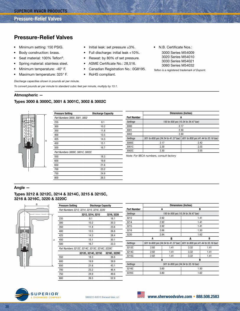
Pressure Setting Discharge Capacity
Part Numbers 3000, 3001, 3002
235 8.1
300 10.2
350 11.8
400 13.5
425 14.3
450 15.1
500 16.7
Part Numbers 3000C, 3001C, 3002C
550 18.3
600 19.9
650 21.6
700 23.2
750 24.9
800 26.5
Pressure Setting Discharge Capacity
Part Numbers 3212, 3214, 3215, 3216, 3220
3212, 3214, 3215 3216, 3220235 8.1 16.1
300 10.2 20.3
350 11.8 23.6
400 13.5 26.8
425 14.3 28.4
450 15.1 30.1
500 16.7 33.3
Part Numbers 3212C, 3214C, 3215C, 3216C, 3220C
3212C, 3214C, 3215C 3216C, 3220C550 18.3 36.6
600 19.9 39.9
650 21.6 43.1
700 23.2 46.4
750 24.9 49.6
800 26.5 52.9
Note: For IBCA numbers, consult factory
Discharge capacities shown in pounds air per minute.
To convert pounds air per minute to standard cubic feet per minute, multiply by 13.1.
Atmospheric —
Types 3000 & 3000C, 3001 & 3001C, 3002 & 3002C
Angle —
Types 3212 & 3212C, 3214 & 3214C, 3215 & 3215C, 3216 & 3216C, 3220 & 3220C
Part Number
Dimensions (Inches)
A
Settings 150 to 500 psi (10.34 to 34.47 bar)
3000 2.17
3001 2.30
3002 2.30
Settings 501 to 600 psi (34.54 to 41.37 bar) 601 to 800 psi (41.44 to 55.16 bar)
3000C 2.17 2.42
3001C 2.30 2.55
3002C 2.30 2.55
Part NumberDimensions (Inches)
A B
Settings 150 to 500 psi (10.34 to 34.47 bar)
3212 2.92 1.41
3214 2.92 1.41
3215 2.92 1.41
3216 2.66 1.50
3220 2.84 1.62
A B A B
Settings 501 to 600 psi (34.54 to 41.37 bar) 601 to 800 psi (41.44 to 55.16 bar)
3212C 2.92 1.41 3.32 1.41
3214C 2.92 1.41 3.32 1.41
3215C 2.92 1.41 3.32 1.41
A B
Settings 501 to 800 psi (34.54 to 55.16 bar)
3216C 3.60 1.50
3220C 3.80 1.62
Pressure-Relief ValvesPressure-Relief Valves
2121
S U P E R I O RA SHERWOOD COMPANY SWD0215 ©2015 Sherwood Valve, LLC www.sherwoodvalve.com • 888.508.2583MADE IN USA
SUPERIOR HVACR PRODUCTS
Pressure-Relief ValvesPressure-Relief Valves
Pressure-Relief Valves
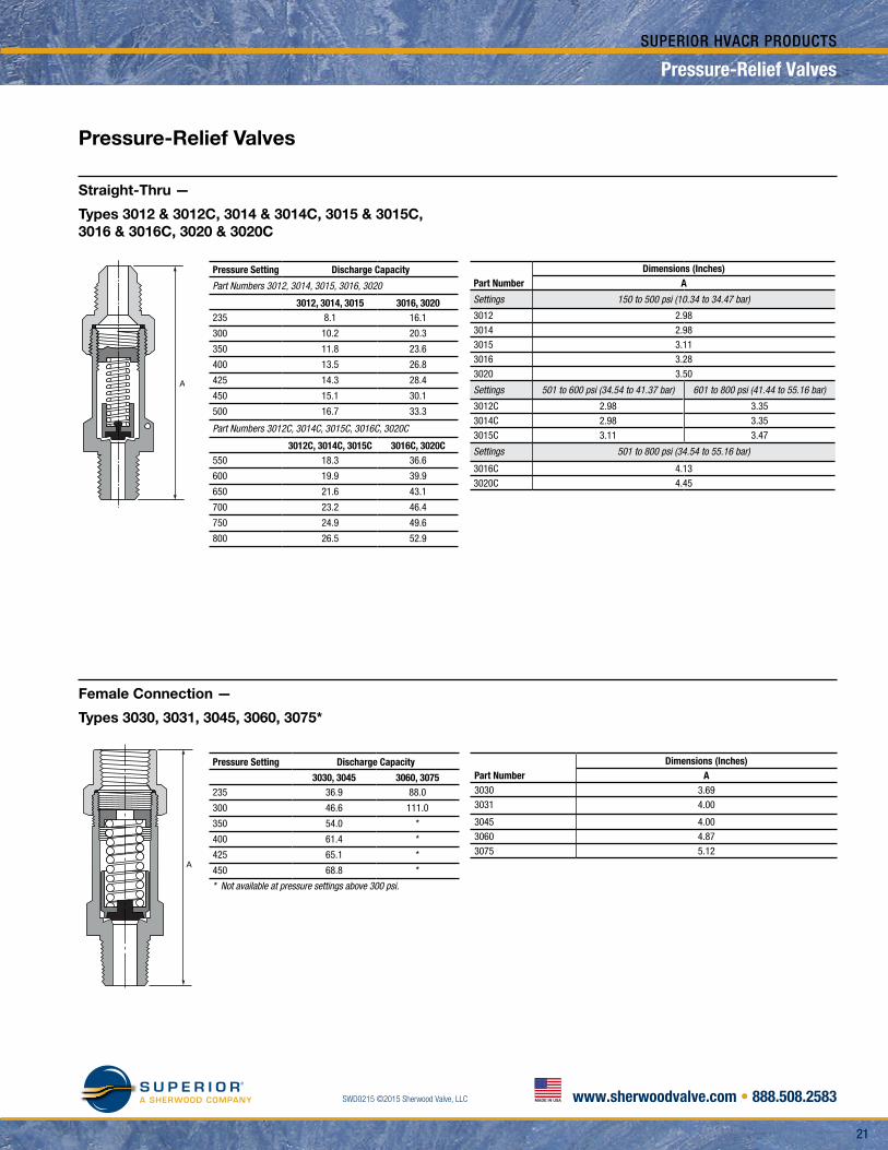
Pressure Setting Discharge Capacity
Part Numbers 3012, 3014, 3015, 3016, 3020
3012, 3014, 3015 3016, 3020235 8.1 16.1
300 10.2 20.3
350 11.8 23.6
400 13.5 26.8
425 14.3 28.4
450 15.1 30.1
500 16.7 33.3
Part Numbers 3012C, 3014C, 3015C, 3016C, 3020C
3012C, 3014C, 3015C 3016C, 3020C550 18.3 36.6
600 19.9 39.9
650 21.6 43.1
700 23.2 46.4
750 24.9 49.6
800 26.5 52.9
Pressure Setting Discharge Capacity
3030, 3045 3060, 3075235 36.9 88.0
300 46.6 111.0
350 54.0 *
400 61.4 *
425 65.1 *
450 68.8 *
* Not available at pressure settings above 300 psi.
Straight-Thru —
Types 3012 & 3012C, 3014 & 3014C, 3015 & 3015C, 3016 & 3016C, 3020 & 3020C
Female Connection —
Types 3030, 3031, 3045, 3060, 3075*
Part NumberDimensions (Inches)
A
Settings 150 to 500 psi (10.34 to 34.47 bar)
3012 2.98
3014 2.98
3015 3.11
3016 3.28
3020 3.50
Settings 501 to 600 psi (34.54 to 41.37 bar) 601 to 800 psi (41.44 to 55.16 bar)
3012C 2.98 3.35
3014C 2.98 3.35
3015C 3.11 3.47
Settings 501 to 800 psi (34.54 to 55.16 bar)
3016C 4.13
3020C 4.45
Part NumberDimensions (Inches)
A3030 3.69
3031 4.00
3045 4.00
3060 4.87
3075 5.12A
22
S U P E R I O RA SHERWOOD COMPANY
22
SWD0215 ©2015 Sherwood Valve, LLC www.sherwoodvalve.com • 888.508.2583MADE IN USA
SUPERIOR HVACR PRODUCTS
To select a pressure-relief valve, it is necessary first to determine the discharge capacity required to protect the refrigerant-containing vessel under consideration. The ANSI/ASHRAE Standard 15 states that the required discharge capacity of a pressure-relief valve used on such a vessel is directly proportional to the size of the vessel. Once the size of the vessel to be protected is known, the required discharge capacity of the pressure-relief valve may then be determined by using the following formula:
C=ƒDL
Where: C = minimum required discharge capacity of the pressure-relief device in pounds of air per minute (kg/sec). ƒ = factor dependent upon type of refrigerant1. (See Table 1 below) D = outside diameter of vessel in feet (m). L = length of vessel in ft. (m).
Table 1
Refrigerant ..............................................................Value of ƒ
When used on the low side of a limited-charge cascade system (Values in parentheses are metric):
R-23, R-170, R-744, R-1150, R-508A, R-508B .......1.0 (0.082)
R-13, R-13B1, R-503 ...............................................2.0 (0.163)
R-14 .........................................................................2.5 (0.203)
Other applications:
R-718 .......................................................................0.2 (0.016)
R-717 .......................................................................0.5 (0.041)
R-11, R-32, R-113, R-123, R-142b, R-152a, R-290, R-600, R-600a, R-764 ....................1.0 (0.082)
R-12, R-22, R-114, R-124, R-134a, R-401A, R-401B, R-401C, R-405A, R-406A, R-407C, R-407D, R-407E, R-409A, R-409B, R-411A, R-411B, R-411C, R-412A, R-414A, R-414B, R-500, R-1270 ..........................................................1.6 (0.131)
R-143a, R-402B, R-403A ..........................................2.0 (0.163) R-407A, R-408A, R-413A .........................................2.0 (0.163)
R-115, R-402A, R-403B, R-404A, R-407B, R-410A, R-410B, R-502, R-507A, R-509A ...............2.5 (0.203)
Example: What is the required discharge capacity of a pressure-relief valve to be used on an R-22 receiver that is 14" in diameter and 42" long having a design working pressure of 320 psi?
Solution: D = 1.167 ft., L = 3.5 ft., and ƒ = 1.6 from Table 1: C = ƒDL = 1.6 x 1.167 x 3.5 C = 6.5 lbs. air/min.
In other words, under the conditions listed above, a receiver of this size requires a pressure-relief valve with a minimum discharge capacity of 6.5 pounds of air per minute at a pressure setting of 320 PSIG.
Pressure-Relief Valve Settings
All pressure-relief valves are rated according to their discharge capacity either in pounds of air per minute or kg/sec. at a given pressure setting. Under the ANSI/ASHRAE 15 Standard, pressure-relief valves shall start to function at a pressure not to exceed the design pressure of the parts of the system protected.
Generally, a pressure-relief valve may be set so that its initial leak is 100% of the design working pressure of the pressure vessel, regardless of the type of refrigerant used. The method of determining set pressure is outlined in Section 9.2 of the ANSI/ASHRAE Standard 15.
Sherwood manufactures pressure-relief valves in standard settings of 235, 300, 350, 400, 425 and 450 PSIG. Relief valves with settings other than standard may be ordered from the factory at a slight additional cost.
Capacity of Pressure-Relief Valves
Flow capacities of Superior pressure-relief valves are expressed in either pounds of air per minute or standard cubic feet per minute. To convert pounds of air per minute to standard cubic feet per minute, multiply by 13.1.
To determine the pressure-relief valve capacities at any pressure setting between 150 and 450 PSIG, use the following formula:
C = S(1.1P+14.7)
Where: C = Pressure-relief valve capacity in pounds of air per minute P = Pressure setting of relief valve in PSIG S = Pressure-relief valve flow factor
Values of “S” flow factor for each pressure-relief valve series are given in Table 2. Table 2 (pg. 23) gives the certified flow ratings in pounds of air per minute for all of the pressure-relief valve series at the standard pressure settings.
Selection of Relief Valves for Commercial Refrigeration and Air Conditioning Applications Based on ANSI/ASHRAE Standard 15
Selection of Relief ValvesSelection of Relief Valves
2323
S U P E R I O RA SHERWOOD COMPANY SWD0215 ©2015 Sherwood Valve, LLC www.sherwoodvalve.com • 888.508.2583MADE IN USA
SUPERIOR HVACR PRODUCTS
Selection of Relief ValvesSelection of Relief Valves
Table 2
CERTIFIED FLOW RATINGS — for standard settings
Flow capacity as determined by the National Board of Boiler and Pressure Vessel Inspectors in accordance with A.S.M.E. Code, Section VIII, Division 1, and as required by ANSI/ASHRAE Standard 15: Safety Code For Mechanical Refrigeration.
Series 3000 3020 3030 3060
Flow Factor “S” 0.0296 0.059 0.135 0.322
Part Number
3000, 3000C 3015, 3015C 3016, 3016C 3030 3060
3001, 3001C 3212, 3212C 3020, 3020C 3031 3075
3002, 3002C 3214, 3214C 3216, 3216C 3045
3012, 3012C 3215, 3215C 3220, 3220C
3014, 3014C
Example: What is the flow capacity of a Sherwood 3045 pressure-relief valve set to 350 PSIG?
Solution: Referring to Table 2, we find that a 3045 pressure- relief valve is part of the 3030A Series and that its flow capacity is 54.0 lbs. air/min. The calculation goes as follows:
“S” factor from Table 2 for the 3030A Series is 0.135. Therefore:
C = S(1.1P+14.7) = 0.135 x ([1.1]) x 350 + 14.7) C = 54.0 lbs. air/min.
To convert 54.0 lbs. air/min. to SCFM:
C = 54.0 x 13.1 = 707.4 SCFM
As you will note from Table 2, the higher the set pressure, the greater the flow capacity of the pressure-relief valve.
General Regulations and Recommendations
1. Pressure-relief valves are installed in a refrigeration system primarily to protect the receiver or other pressure vessel in the event of a fire or any other emergency high-pressure conditions. Fuse plugs protect only in the event of fire.
2. All systems must have a pressure-relief valve or a fuse plug installed in order to comply with the ANSI/ASHRAE Standard 15.
3. Pressure vessels with an internal gross volume of 3 ft.3 (0.085 m3) or less shall use one or more pressure-relief devices or a fusible plug.
Note: Local codes may require pressure-relief valves on receivers smaller than 3 ft.3.
4. Pressure vessels of more than 3 ft.3 (0.085 m3) but less than 10 ft.3 (0.285 m3) internal gross volume shall use one or more pressure-relief devices. Fusible plugs are not permitted and should not be used.
5. Pressure vessels of 10 ft.3 (0.285 m3) or more internal gross volume use a single rupture member or dual pressure- relief valves when discharging to the atmosphere. Dual pressure-relief valves are installed with a three-way valve to allow testing or repairs (See Sherwood 3155W Series Valves). A three-way valve used in conjunction with the dual pressure-relief valves is not considered a stop valve.
6. Fuse plugs are temperature responsive relief devices only, and for all practical purposes, can only be considered as protection for the receiver of the system in cases of fire when the fire is in the immediate vicinity of the fuse plug.
7. Sherwood recommends the use of spring-loaded pressure- relief devices, such as our four series of pressure-relief valves. They are pressure sensitive and add an additional protection against abnormal system pressures.
8. Sherwood pressure-relief valves are approved and tested as required by Section VIII, Division 1 of the ASME Boiler and Pressure Vessel Code. All valves have pertinent data marked on the side of the valve body as required by the ASME Boiler and Pressure Vessel Code.
9. The pressure-relief valve set pressure cannot be higher than the design working pressure of the pressure vessel it is protecting, but, if conditions permit, the pressure-relief valve set pressure should be at least 25% higher than the maximum normal operating pressure.
10. All pressure-relief valves installed on the high side must be in a vapor space as near to the receiver as practical. Stop valves cannot be placed in the line between the pressure- relief valve and the pressure vessel it is protecting. In general, the pressure-relief valve should be installed directly to the receiver above the liquid level or as near to the inlet of the receiver as practical. All pipe and fittings between the pressure-relief valve and the parts of the system it protects must have at least the same diameter of the pressure-relief valve inlet diameter.
11. The size of discharge pipe from a pressure-relief valve must not be less than the outlet size of the pressure-relief valve. See ANSI/ASHRAE Standard 15 for requirements and guidelines on discharge piping.
12. Prior to installation or during pressure vessel testing, Sherwood pressure-relief valves should not be discharged. Any dirt in the system may imbed in the seat and prevent the pressure-relief valve from resealing properly.
13. The statements in this document reflect and are taken directly from ANSI/ASHRAE Standard 15-1994 and ANSI/ASHRAE Addendum 15c-2000. Please consult these standards for any additional information.
Note: Relief valves are non-returnable. The policy helps maintain product integrity.