Embed Size (px)
Citation preview
www.troteclaser.com
Speedy 360 Operation Manual
BA 8030_2.0_EN (01/2016)
ENGLISH
Speedy 360
BA 8030_2.0_EN (01/2016) 2 / 84
www.troteclaser.com
Trotec Laser GmbH
Linzer Straße 156
A – 4600 Wels
AUSTRIA
Tel.: ++43/7242/239-7000
Fax: ++43/7242/239-7380
E-Mail: [email protected]
www.troteclaser.com
Technical Changes
Technical specifications are subject to change without notice. Trotec Laser GmbH reserves the right to improve or modify any product described herein without prior notice.
Copyright This documentation with all illustrations is intellectual property of Trotec Laser GmbH. The entire documentation is given to the user for personal use only. Reproduction, translation or any distribution to third parties is not permitted without the prior consent of Trotec Laser GmbH. Any infringement will be prosecuted.
Speedy 360
BA 8030_2.0_EN (01/2016) 3 / 84
www.troteclaser.com
Contents
1 General .............................................................................................................................................. 6
1.1 Information about this operation manual .................................................................................... 6 1.1.1 Storage of the manual ...................................................................................................... 6
1.1.2 Complementary documentation ....................................................................................... 6 1.2 Explanation of symbols ............................................................................................................... 7 1.3 Liability and warranty .................................................................................................................. 8 1.4 Scope of delivery (standard configuration) ................................................................................. 9 1.5 Type plate ................................................................................................................................. 10
2 Safety ............................................................................................................................................... 11
2.1 Safety principles ....................................................................................................................... 11
2.1.1 Intended use ................................................................................................................... 11 2.1.2 Improper use .................................................................................................................. 11 2.1.3 Safety norms and regulations ......................................................................................... 12
2.2 Laser safety .............................................................................................................................. 13
2.2.1 Laser classes.................................................................................................................. 13 2.3 Machine modification ................................................................................................................ 14 2.4 Responsibilities of the operator ................................................................................................ 15 2.5 Personnel qualifications ............................................................................................................ 16
2.6 Warning and information labels ................................................................................................ 17 2.7 Safety devices .......................................................................................................................... 19
2.7.1 Main switch ..................................................................................................................... 20 2.7.2 Key switch ...................................................................................................................... 20 2.7.3 Temperature sensor reset button (Option) ..................................................................... 20
2.7.4 Emergency stop button (only with temperature sensor option) ...................................... 21
2.7.5 Interlock switches ........................................................................................................... 21 2.7.6 Side panels ..................................................................................................................... 21 2.7.7 Acrylic top lid .................................................................................................................. 21
2.7.8 Protective measures ....................................................................................................... 22 2.8 In case of an emergency .......................................................................................................... 22
2.8.1 In case of malfunction .................................................................................................... 22
2.8.2 In case of accident; First Aid .......................................................................................... 22 2.9 Specific hazards ....................................................................................................................... 23
2.9.1 Fire hazard ..................................................................................................................... 23 2.9.2 Gases, fumes and dust .................................................................................................. 23 2.9.3 Optical components ........................................................................................................ 24
3 EC Declaration of Conformity ....................................................................................................... 26
4 Technical Data ................................................................................................................................ 27
4.1 Dimensions and weight............................................................................................................. 27 4.2 Data sheet ................................................................................................................................ 28 4.3 Electrical requirements ............................................................................................................. 31
4.4 Exhaust system requirements .................................................................................................. 32 4.5 Computer requirements ............................................................................................................ 33 4.6 Materials ................................................................................................................................... 34
5 Machine overview ........................................................................................................................... 36
5.1 General overview ...................................................................................................................... 36

Speedy 360
BA 8030_2.0_EN (01/2016) 4 / 84
www.troteclaser.com
5.1.1 Operation panel .............................................................................................................. 37 5.1.2 Front door ....................................................................................................................... 39
5.2 Tables (multifunctional table concept) ...................................................................................... 40
5.2.1 Multifunctional base frame ............................................................................................. 40 5.2.2 Ferromagnetic engraving table (standard) ..................................................................... 40 5.2.3 Vacuum table.................................................................................................................. 40 5.2.4 Cutting tables.................................................................................................................. 41 5.2.5 Additional tabletops ........................................................................................................ 42
5.3 Lenses and nozzles .................................................................................................................. 43 6 Transport, packaging and storage ............................................................................................... 44
6.1 Safety notes .............................................................................................................................. 44 6.2 Transport and unloading ........................................................................................................... 44
6.2.1 Required tools ................................................................................................................ 44 6.2.2 Transport conditions ....................................................................................................... 45
6.3 Storage and storage conditions ................................................................................................ 46 6.4 Unpacking the machine ............................................................................................................ 47 6.5 Transport inspection and reporting of defects .......................................................................... 49 6.6 Relocation of the machine ........................................................................................................ 49
7 Setup and installation .................................................................................................................... 50
7.1 Safety notes .............................................................................................................................. 50 7.2 Operating environment ............................................................................................................. 51
7.2.1 Space requirements ....................................................................................................... 52
7.3 Setup......................................................................................................................................... 52 7.4 Connections .............................................................................................................................. 53
7.4.1 Connecting the mains ..................................................................................................... 54
7.4.2 Connecting the PC ......................................................................................................... 54
7.4.3 Connecting a Trotec exhaust system ............................................................................. 55 8 Operation ......................................................................................................................................... 56
8.1 Before operation ....................................................................................................................... 56
8.2 Software .................................................................................................................................... 56 8.3 Power ON/OFF ......................................................................................................................... 57
8.3.1 Power ON ....................................................................................................................... 57
8.3.2 Power OFF ..................................................................................................................... 57 8.4 Lens placement ........................................................................................................................ 58
8.4.1 Lens position .................................................................................................................. 58 8.5 Table placement ....................................................................................................................... 59 8.6 Focusing methods .................................................................................................................... 60
8.6.1 Focus tool ....................................................................................................................... 61
8.6.2 Software focus ................................................................................................................ 61 8.6.3 Light bar focus ................................................................................................................ 62 8.6.4 Sonar Technology™ ....................................................................................................... 62
8.7 Rotary engraving attachment (option) ...................................................................................... 63 8.7.1 Installation and commissioning ...................................................................................... 64 8.7.2 Mounting the work piece ................................................................................................ 65 8.7.3 Engraving ....................................................................................................................... 66
8.8 Tips and tricks ........................................................................................................................... 67 8.8.1 Tips and tricks for laser engraving ................................................................................. 67
Speedy 360
BA 8030_2.0_EN (01/2016) 5 / 84
www.troteclaser.com
8.8.2 Tips and tricks for laser cutting ....................................................................................... 68 8.8.3 Tips and tricks for the production of rubber dies ............................................................ 68
9 Maintenance .................................................................................................................................... 69
9.1 Safety notes .............................................................................................................................. 69 9.2 Maintenance schedule .............................................................................................................. 70 9.3 Cleaning the machine ............................................................................................................... 71
9.3.1 Cleaning the exhaust box ............................................................................................... 72
9.4 Cleaning the optics ................................................................................................................... 73 9.4.1 Cleaning the lens ............................................................................................................ 73 9.4.2 Cleaning the mirror ......................................................................................................... 74
9.5 Cleaning the ultrasonic sensor (Option Sonar Technology™) ................................................. 75 10 Troubleshooting ............................................................................................................................. 76
10.1 Errors, cause and resolutions ................................................................................................... 76 11 Contact details ................................................................................................................................ 78
11.1 Technical Support ..................................................................................................................... 78 11.2 Local Offices / Sales ................................................................................................................. 78
11.3 Technical Documentation ......................................................................................................... 78 12 Disassembly.................................................................................................................................... 79
13 Disposal ........................................................................................................................................... 79
14 Appendix ......................................................................................................................................... 80
14.1 Acceptance form ....................................................................................................................... 80
14.2 Training verification form .......................................................................................................... 81 14.3 Response form ......................................................................................................................... 82
14.4 How to create a service file....................................................................................................... 83
Speedy 360
BA 8030_2.0_EN (01/2016) 6 / 84
www.troteclaser.com
1 General
1.1 Information about this operation manual
PLEASE READ THIS OPERATION MANUAL CAREFULLY BEFORE USE
KEEP THE MANUAL FOR FURTHER CONSULTATION
This operation manual describes how to operate the machine properly and safely. Be sure to follow
the safety instructions given here, as well as any local accident prevention regulations and general
safety regulations applicable to the field of usage.
Before beginning any work on the machine, ensure that the manual, in particular the chapter entitled
“Safety Information” and the respective safety guidelines, has been read in its entirety and fully
understood.
1.1.1 Storage of the manual
This manual is an integral part of the machine and must therefore be kept in the direct vicinity of the
machine and be accessible at all times.
1.1.2 Complementary documentation
Software Operation Manual
Trotec JobControl® JobControl_Operationmanual_x.x.x_Vx.x
Speedy 360
BA 8030_2.0_EN (01/2016) 7 / 84
www.troteclaser.com
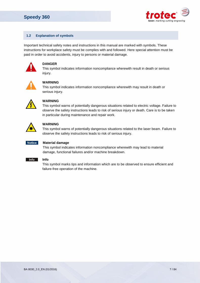
1.2 Explanation of symbols
Important technical safety notes and instructions in this manual are marked with symbols. These
instructions for workplace safety must be complies with and followed. Here special attention must be
paid in order to avoid accidents, injury to persons or material damage.
DANGER
This symbol indicates information noncompliance wherewith result in death or serious
injury.
WARNING
This symbol indicates information noncompliance wherewith may result in death or
serious injury.
WARNING
This symbol warns of potentially dangerous situations related to electric voltage. Failure to
observe the safety instructions leads to risk of serious injury or death. Care is to be taken
in particular during maintenance and repair work.
WARNING
This symbol warns of potentially dangerous situations related to the laser beam. Failure to
observe the safety instructions leads to risk of serious injury.
Material damage
This symbol indicates information noncompliance wherewith may lead to material
damage, functional failures and/or machine breakdown.
Info
This symbol marks tips and information which are to be observed to ensure efficient and
failure-free operation of the machine.

Speedy 360
BA 8030_2.0_EN (01/2016) 8 / 84
www.troteclaser.com
1.3 Liability and warranty
All information, illustrations, tables, specifications and diagrams contained in this operation manual
have been carefully compiled according to the current state of technology. No liability is accepted with
regard to errors, missing information and any resulting damage or consequential loss.
Strict compliance with the safety procedures described in this operation manual and extreme caution
when using the equipment are essential for avoiding and reducing the possibility of personal injury or
damage to the equipment. The manufacturer shall not be liable for any damage and or faults resulting
from non-observance of instructions in the manual.
Additionally, Trotec Laser GmbH shall not be held responsible for any personal injury or property
damage, of either an indirect or specific nature, consequential loss, loss of commercial profits,
interruption to business, or loss of commercial information resulting from use of the equipment
described in this manual.
Furthermore, Trotec Laser GmbH shall accept no liability whatsoever for damage caused by the use of
non-original parts and accessories.
Any software forming part of this equipment may be used only for the purposes for which it was
supplied by Trotec Laser GmbH. It is strictly prohibited to make any alterations, to prepare
translations, decompile or disassemble the software.
Trotec Laser GmbH reserves the right to update any of the information, illustrations, tables,
specifications and diagrams contained in this operation manual with regard to technical developments
at any time without notice.
Speedy 360
BA 8030_2.0_EN (01/2016) 9 / 84
www.troteclaser.com
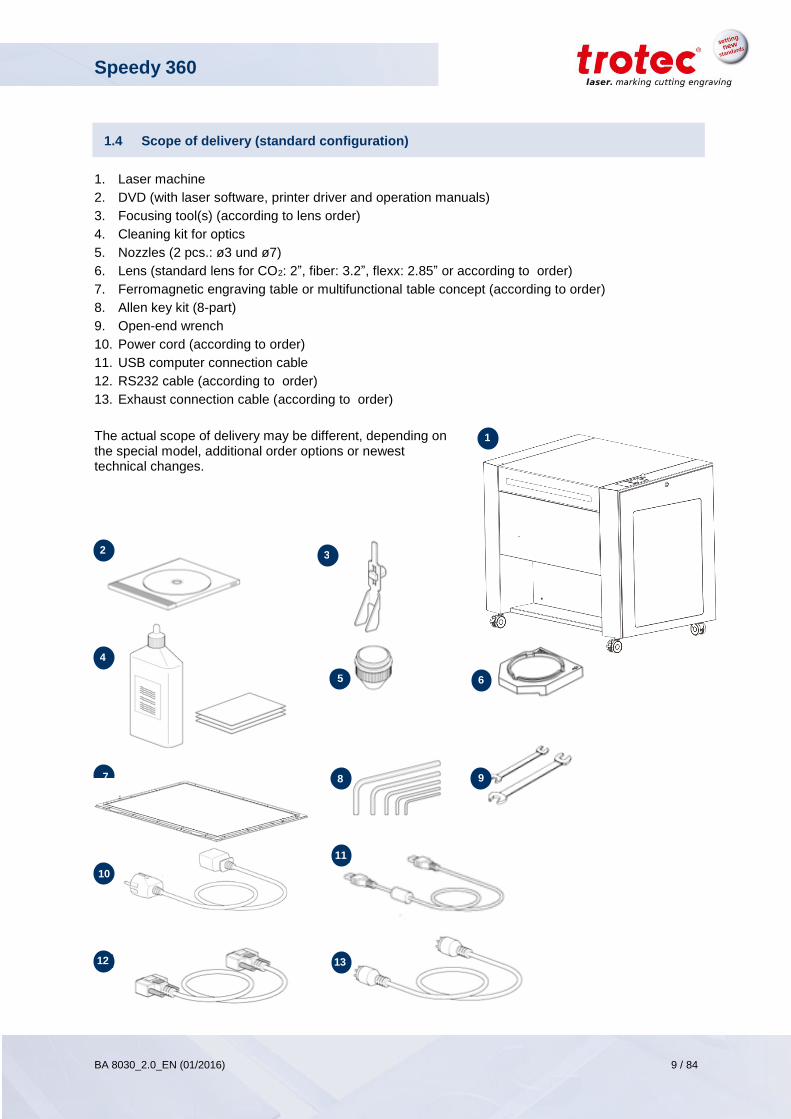
1.4 Scope of delivery (standard configuration)
1. Laser machine
2. DVD (with laser software, printer driver and operation manuals)
3. Focusing tool(s) (according to lens order)
4. Cleaning kit for optics
5. Nozzles (2 pcs.: ø3 und ø7)
6. Lens (standard lens for CO2: 2”, fiber: 3.2”, flexx: 2.85” or according to order)
7. Ferromagnetic engraving table or multifunctional table concept (according to order)
8. Allen key kit (8-part)
9. Open-end wrench
10. Power cord (according to order)
11. USB computer connection cable
12. RS232 cable (according to order)
13. Exhaust connection cable (according to order)
The actual scope of delivery may be different, depending on the special model, additional order options or newest technical changes.
3 2
1
4
5 6
7 9 8
10
11
12 13
Speedy 360
BA 8030_2.0_EN (01/2016) 10 / 84
www.troteclaser.com
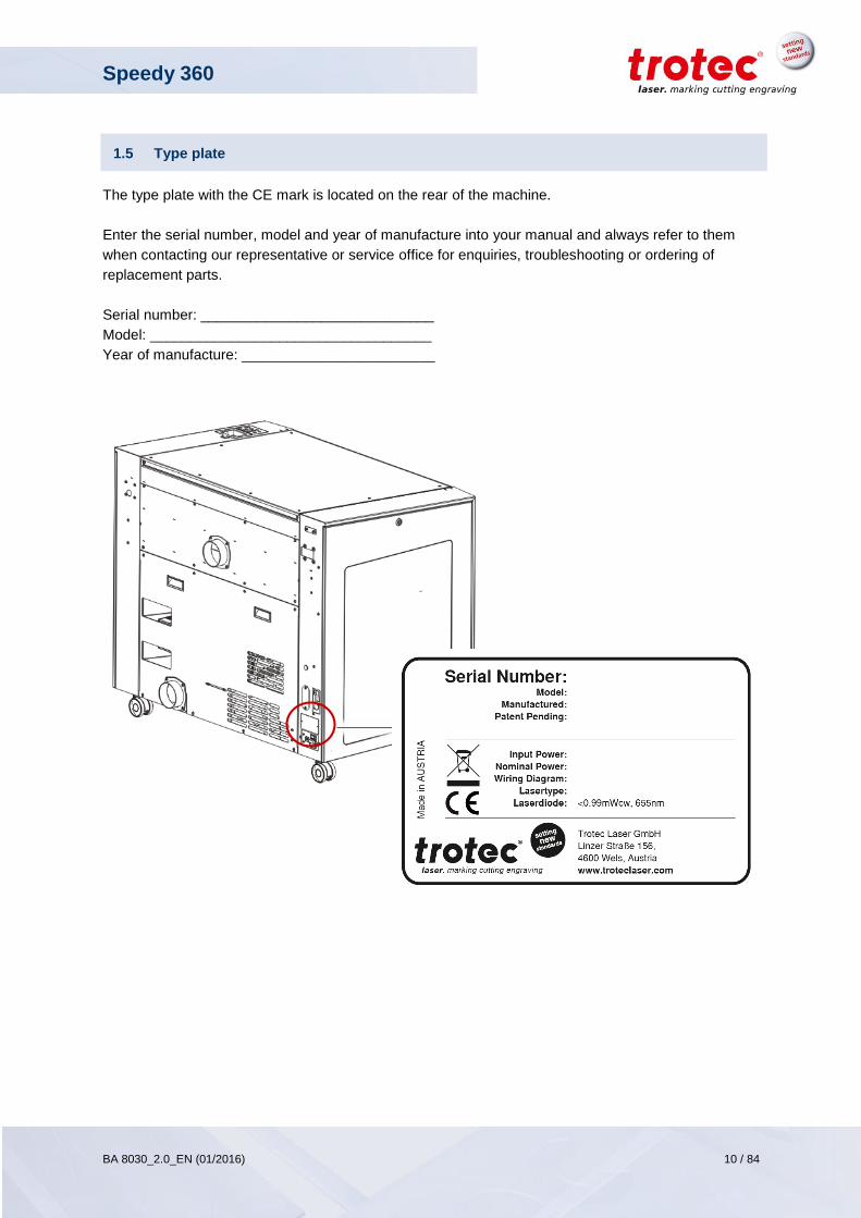
1.5 Type plate
The type plate with the CE mark is located on the rear of the machine.
Enter the serial number, model and year of manufacture into your manual and always refer to them
when contacting our representative or service office for enquiries, troubleshooting or ordering of
replacement parts.
Serial number: _____________________________
Model: ___________________________________
Year of manufacture: ________________________
Speedy 360
BA 8030_2.0_EN (01/2016) 11 / 84
www.troteclaser.com
2 Safety
At the time of the development and production of the machine, it was built in accordance with
recognized technological regulations and is therefore considered operationally safe.
However, hazards may arise if the machine is used improperly, operated by untrained personnel or
employed for purposes other than those it was designed for.
The present chapter provides an overview of all important safety considerations necessary to ensure
safe and trouble-free operation of the machine.
Other chapters of this manual contain specific safety instructions which are marked with symbols in
order to avert dangers.
2.1 Safety principles
2.1.1 Intended use
The machine described in this manual is intended exclusively for laser marking using the supplied
marking software.
The system must be operated, maintained and repaired only by trained personnel familiar with the
designated field of use and the dangers of the machine!
Operate the machine only in technically flawless condition and when it fully complies with the EC
Machinery Directive.
For material details see chapter “Materials” or contact your local Trotec salesperson or Trotec
technical support.
The intended use of this machine also includes that all personnel involved in installation, set-up,
operation maintenance and repair of the machine must have read and understood the Operation
Manual and in particular the “Safety” section, and comply with the instructions.
2.1.2 Improper use
Use of the machine for any purposes other than those intended or described in the present manual is
regarded as improper and therefore prohibited.
Trotec will not accept any liability for damage caused by improper use. The risks in case of improper
use are exclusively borne by the user.
Non-observance of the operation, maintenance and service instructions described within this manual
absolves Trotec from any liability in case of a defect.
Speedy 360
BA 8030_2.0_EN (01/2016) 12 / 84
www.troteclaser.com
2.1.3 Safety norms and regulations
The following directives and guidelines must be observed to avoid hazards when operating Trotec laser systems:
EN 60825-1 Safety of Laser Products - Part 1: Equipment Classification and Requirements
EN 60950 Information Technology Equipment – Safety
EN 61010-1 Safety Requirements for Electrical Equipment for Measurement, Control and
Laboratory Use; General Requirements
BGV B2 (VBG93) Laser Radiation
UL 60950 Standard for Safety for Information Technology Equipment
UL 31011-1 Electrical Equipment for Laboratory Use – Part 1: General
21 CFR 1040.10 Performance Standard for Light-Emitting Products – Specific Laser Products
21 CFR 1040.11 Performance Standard for Light-Emitting Products – Specific-Purpose Laser
Products
The general guidelines and directives listed above may differ according to locality, region or country. Therefore, always observe the directives applicable to you. The operator is responsible for fulfilling all safety requirements, as Trotec Laser GmbH has no influence on the proper use of the machine.
Speedy 360
BA 8030_2.0_EN (01/2016) 13 / 84
www.troteclaser.com
2.2 Laser safety
The laser safety class indicates the risk potential from accessible laser radiation.
The Speedy 360 is a Class 2 (US: Class II) laser marking system as per DIN EN 60825-1 “Safety of
Laser Products”.
The integrated laser source of the Speedy 360 is a Class 4 (US: Class IV) laser marking system
according to DIN EN 60825-1 and identified as such.
2.2.1 Laser classes
WARNING
Laser radiation of Class 2 (US: Class II)
Lasers of Class 2 (US: Class II) are safe, but can cause irritation of the eyes if the natural avoidance reaction (staring into the beam deliberately) or eyelid closure reflex is suppressed.
- Do not suppress the eyelid closure reflex.
- Do not stare directly into the beam.
- Close eyes, turn away.
- Never look at the laser beam directly with an optical instrument, e.g. a lens.
The accessible laser radiation of Class 2 (US: Class II) laser systems does not pose any hazard for
the skin. Diffuse reflections as well as any short-term irradiation of the eyes (exposure time max. 0.25
sec) also poses no risk due to the low output power.
However, it is possible to suppress the natural eyelid closure reflex and stare into the class-2 beam for
a time long enough for the eyes to get injured.
WARNING
Laser radiation of Class 4 (US: class IV)
Exposure to laser radiation of Class 4 (US: Class IV) can cause injury to the eyes and skin.
- The skin and eyes must not be exposed to direct or reflected or scattered radiation.
- Wear suitable laser safety protection glasses.

Speedy 360
BA 8030_2.0_EN (01/2016) 14 / 84
www.troteclaser.com
2.3 Machine modification
It is strictly prohibited to alter, refit or modify the machine in any way without the express consent of
the manufacturer.
Likewise, it is strictly prohibited to remove, bridge or bypass any safety devices.
Operating conditions and connection and setup values stated in the data sheet must be complied with
at all times.
Operation of the system is permitted only with original parts and accessories by the manufacturer. Use
of low-quality or third-party parts affects machine safety.

Speedy 360
BA 8030_2.0_EN (01/2016) 15 / 84
www.troteclaser.com
2.4 Responsibilities of the operator
In addition to the safety notes and instructions stated in this manual, consider and observe the local
accident prevention regulations and general safety regulations that apply at the operation site of the
machine.
If the machine is used industrially, the operator is subject to the legal obligations concerning industrial
safety.
All personnel involved in installation, set-up, operation, maintenance and repair of the machine must
have read and understood this Operation Manual and in particular the “Safety” section. The personnel
must be trained and informed about all the functions and potential dangers of the machine.
The user is recommended to prepare company internal instructions considering the occupational
qualifications of the personnel employed in each case, and the receipt of the instruction/Operation
Manual or the participation in the introduction/training should in each case be acknowledged in writing.
Keep this manual in the immediate vicinity of the machine so that it is accessible at all times to all
persons working on or with the machine.
It is the duty of the operator to check the machine before start of work for externally visible damage
and defects, and to immediately report any changes that appear (including behavior during operation)
that may affect the safety of the machine. It must be made sure that the machine is operated only in
perfect condition.
The machine must not be left unattended while it is operating.
A CO2 fire extinguisher must always be at hand, as the laser beam can ignite flammable materials.
Do not store any flammable materials in the working area or in the immediate vicinity of the device.
Particularly, residues of processed materials have to be removed to prevent any fire hazard.
The operator must ensure cleanliness and accessibility at and around the machine by corresponding
instructions and controls.
Maintenance and repair work as specified in the present operation manual must be carried out
regularly.
Authority for the individual activities relating to the application of the machine (e.g. installation,
operation, maintenance and cleaning) must be clearly defined and observed, so that no unclear
competencies result under the aspect of safety. This applies in particular to work to be performed on
the electrical equipment that may only be performed by qualified specialists.
For all activities concerning installation, set-up, start-up, operation, modifications of conditions and
methods of operation, maintenance, inspection and repair, the switch-off procedures that may be
provided in the Operation Manual must be observed.
Provide appropriate personal protection equipment (e.g. protective goggles).
Speedy 360
BA 8030_2.0_EN (01/2016) 16 / 84
www.troteclaser.com
Switch off the machine described herein at the main switch for periods of non-use.
Preparation, retooling, change of work piece, maintenance and repair activities must only performed
with equipment switched off, by trained personnel.
Operate the machine described here only with a lens in place. A missing lens may cause the
unfocused beam to be reflected out of the housing.
No working methods are permitted that affect the safety of persons or of the machine.
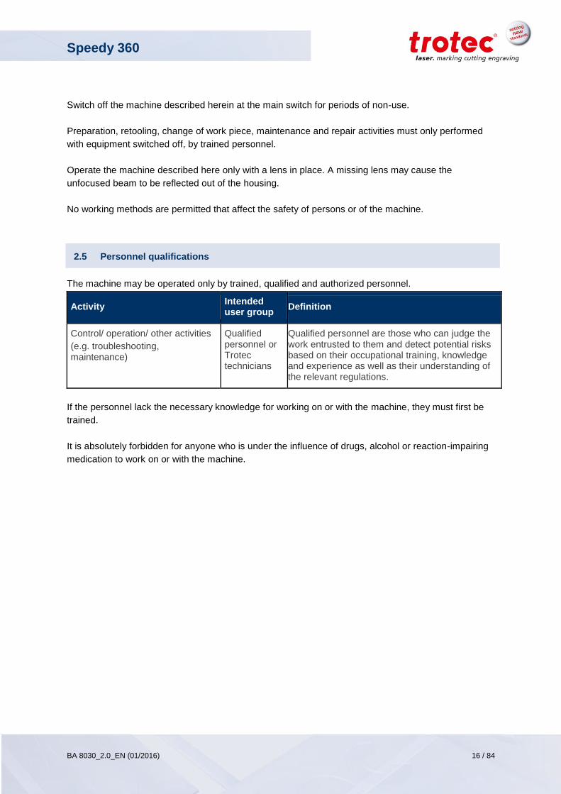
2.5 Personnel qualifications
The machine may be operated only by trained, qualified and authorized personnel.
Activity Intended user group
Definition
Control/ operation/ other activities
(e.g. troubleshooting, maintenance)
Qualified personnel or Trotec technicians
Qualified personnel are those who can judge the work entrusted to them and detect potential risks based on their occupational training, knowledge and experience as well as their understanding of the relevant regulations.
If the personnel lack the necessary knowledge for working on or with the machine, they must first be
trained.
It is absolutely forbidden for anyone who is under the influence of drugs, alcohol or reaction-impairing
medication to work on or with the machine.
Speedy 360
BA 8030_2.0_EN (01/2016) 17 / 84
www.troteclaser.com
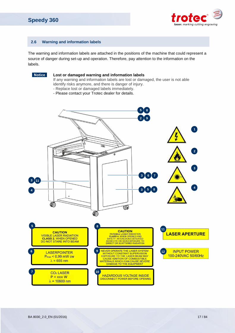
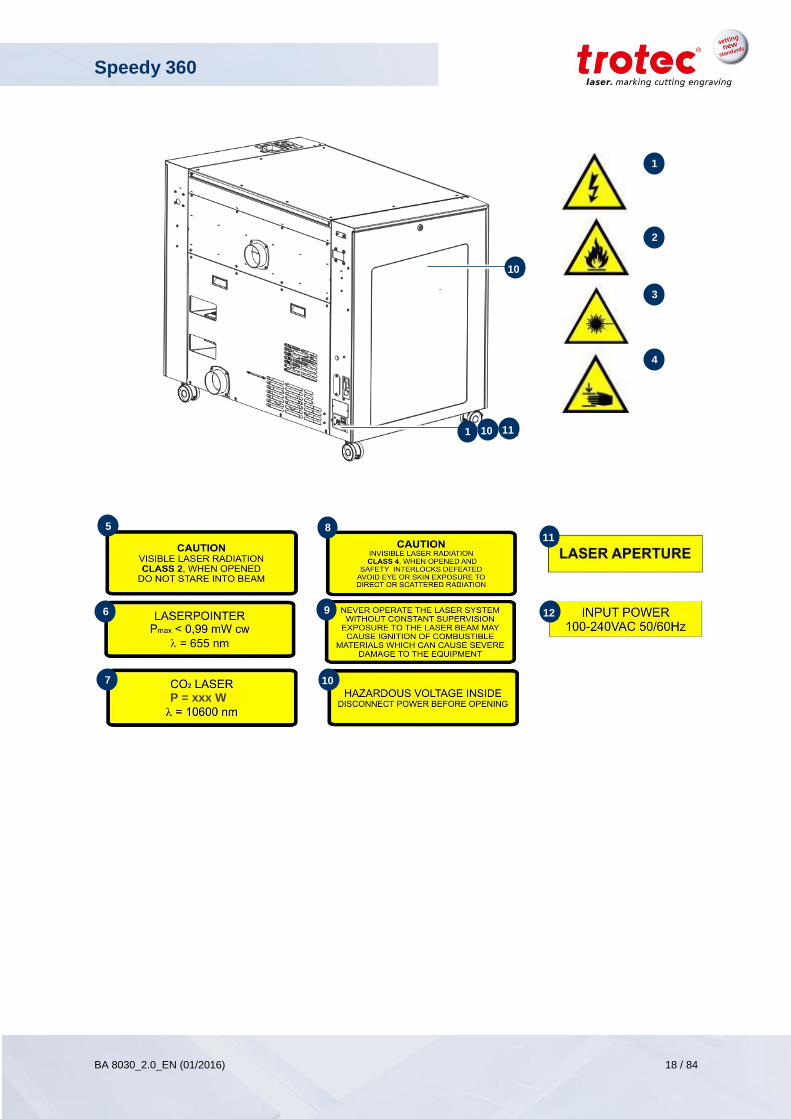
2.6 Warning and information labels
The warning and information labels are attached in the positions of the machine that could represent a
source of danger during set-up and operation. Therefore, pay attention to the information on the
labels.
Lost or damaged warning and information labels If any warning and information labels are lost or damaged, the user is not able identify risks anymore, and there is danger of injury. - Replace lost or damaged labels immediately. - Please contact your Trotec dealer for details.
P = xxx W
4
1
2
3
4
3
3
6 7
2
3 11
5 8
9
5 8
5
6
7
8
9
10
11
12
Speedy 360
BA 8030_2.0_EN (01/2016) 18 / 84
www.troteclaser.com
P = xxx W
11
1
2
3
4
10
10
1
1
5
6
7
8
9
10
11
12
Speedy 360
BA 8030_2.0_EN (01/2016) 19 / 84
www.troteclaser.com
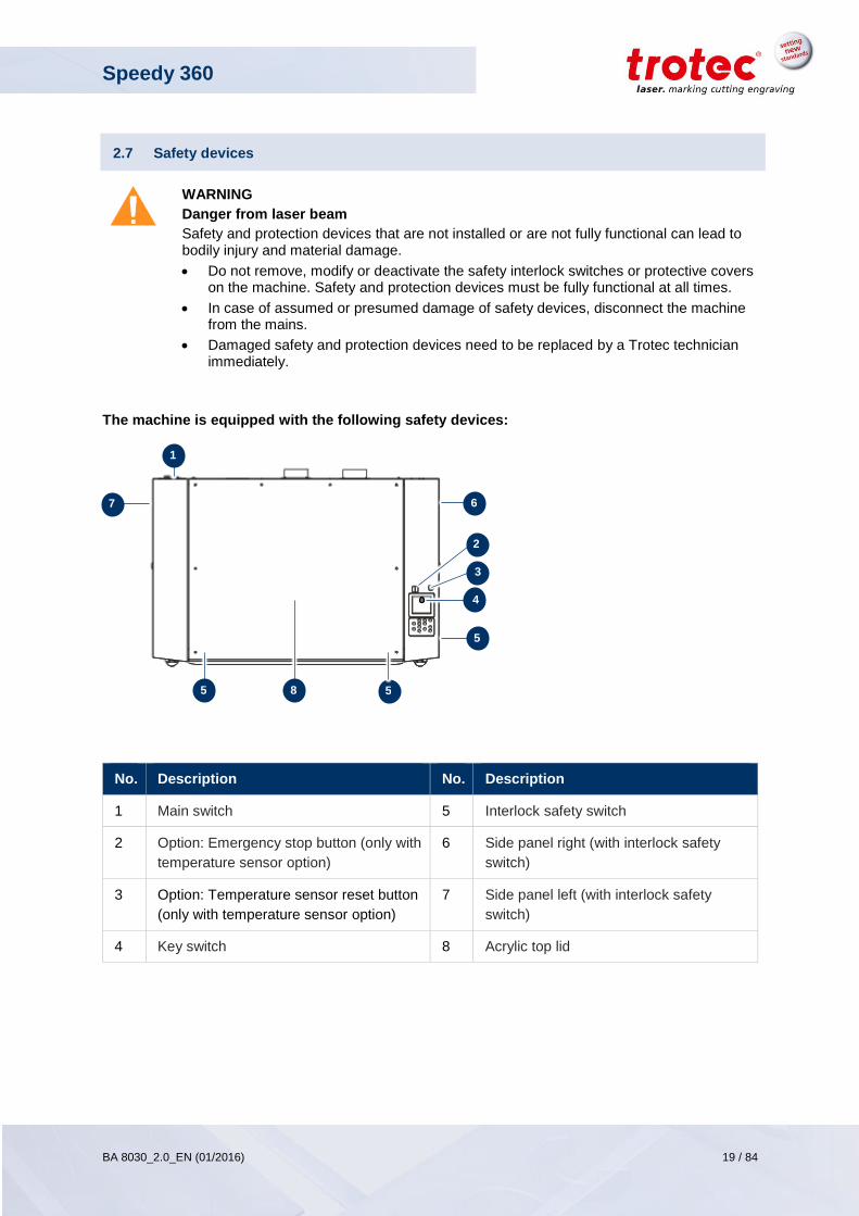
2.7 Safety devices
WARNING
Danger from laser beam
Safety and protection devices that are not installed or are not fully functional can lead to bodily injury and material damage.
Do not remove, modify or deactivate the safety interlock switches or protective covers on the machine. Safety and protection devices must be fully functional at all times.
In case of assumed or presumed damage of safety devices, disconnect the machine from the mains.
Damaged safety and protection devices need to be replaced by a Trotec technician immediately.
The machine is equipped with the following safety devices:
No. Description No. Description
1 Main switch 5 Interlock safety switch
2 Option: Emergency stop button (only with
temperature sensor option)
6 Side panel right (with interlock safety
switch)
3 Option: Temperature sensor reset button
(only with temperature sensor option)
7 Side panel left (with interlock safety
switch)
4 Key switch 8 Acrylic top lid
5
1
4
2
5
5
6 7
8
3
Speedy 360
BA 8030_2.0_EN (01/2016) 20 / 84
www.troteclaser.com
Temperature sensor
reset button
2.7.1 Main switch
The main switch disconnects the machine from the mains power supply.
2.7.2 Key switch
The key switch powers off the motor, laser source and electric system. Through the key switch,
operation by non-authorized personnel can be prevented.
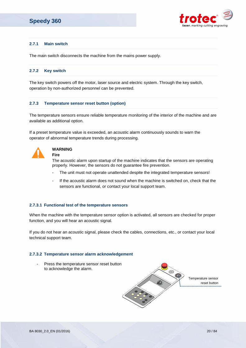
2.7.3 Temperature sensor reset button (option)
The temperature sensors ensure reliable temperature monitoring of the interior of the machine and are
available as additional option.
If a preset temperature value is exceeded, an acoustic alarm continuously sounds to warn the
operator of abnormal temperature trends during processing.
WARNING
Fire
The acoustic alarm upon startup of the machine indicates that the sensors are operating properly. However, the sensors do not guarantee fire prevention.
- The unit must not operate unattended despite the integrated temperature sensors!
- If the acoustic alarm does not sound when the machine is switched on, check that the
sensors are functional, or contact your local support team.
2.7.3.1 Functional test of the temperature sensors
When the machine with the temperature sensor option is activated, all sensors are checked for proper
function, and you will hear an acoustic signal.
If you do not hear an acoustic signal, please check the cables, connections, etc., or contact your local
technical support team.
2.7.3.2 Temperature sensor alarm acknowledgement
- Press the temperature sensor reset button to acknowledge the alarm.
Speedy 360
BA 8030_2.0_EN (01/2016) 21 / 84
www.troteclaser.com
2.7.4 Emergency stop button (only with temperature sensor option)
The emergency stop button, which is located above the operation panel, is present only if the machine
is equipped with an optional temperature sensor.
The emergency stop immediately shuts off the electric circuit. The laser beam is interrupted, and all
movements are stopped.
The function of the emergency stop device is:
Firstly: to prevent any risks to the operating personnel.
Secondly: to avoid any damage to/destruction of the machine/material.
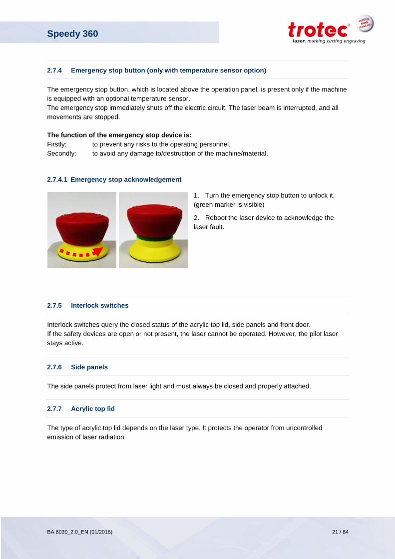
2.7.4.1 Emergency stop acknowledgement
1. Turn the emergency stop button to unlock it.
(green marker is visible)
2. Reboot the laser device to acknowledge the
laser fault.
2.7.5 Interlock switches
Interlock switches query the closed status of the acrylic top lid, side panels and front door.
If the safety devices are open or not present, the laser cannot be operated. However, the pilot laser
stays active.
2.7.6 Side panels
The side panels protect from laser light and must always be closed and properly attached.
2.7.7 Acrylic top lid
The type of acrylic top lid depends on the laser type. It protects the operator from uncontrolled
emission of laser radiation.
Speedy 360
BA 8030_2.0_EN (01/2016) 22 / 84
www.troteclaser.com
2.7.8 Protective measures
In case of actual or presumed damage to the safety devices:
Press the emergency stop button
Disconnect the machine from the mains
Contact your local Trotec Support
2.8 In case of an emergency
2.8.1 In case of malfunction
In case of unusual operating states, open the acrylic top lid to stop working process or respectively
press the emergency stop button, if available and switch off the laser device.
Inform laser protection officer and supervisor.
Follow the operating instructions.
Have repair work performed by Trotec service technicians only.
In case of fire: Use only CO2 extinguisher to quench the fire, insofar as this is possible without
endangering yourself.
2.8.2 In case of accident; First Aid
If due to laser irradiation eye injury has occurred (upon exceedance of the maximum allowable
irradiation rate), the accident victim must immediately be presented to an ophthalmologist.
Assumption of eye injury is justified whenever laser irradiation has occurred and the maximum
allowable irradiation rate may have been exceeded.
First Aider must pay attention to self-protection.
Power off the device.
Remove injured person from the danger zone and provide First Aid. Call emergency physician!
Speedy 360
BA 8030_2.0_EN (01/2016) 23 / 84
www.troteclaser.com
2.9 Specific hazards
2.9.1 Fire hazard
WARNING
Fire hazard
Fire hazard from gas and processing of inflammable materials.
- Do not operate the device without supervision.
- Keep CO2 fire extinguisher ready at hand in the immediate vicinity of the device.
If a main laser beam comes into contact with inflammable material, e.g. paper, the latter
may ignite, quickly leading to fire. Therefore, before switching on the laser and after
deactivating the standby mode you must make sure that there is no inflammable material
in the path of the beam.
Furthermore, gases formed beneath the material being processed may ignite, especially if
the extraction requirements are not met.
The risk of flaming is increased in case of insufficient care and cleaning as well.
Additionally, regularly control the air cooling system on your laser. In particular, the filters
and ventilators should be checked regularly for proper function so as to avoid defects
caused by overheating.
2.9.2 Gases, fumes and dust
Depending on the materials being processed and the parameters selected, laser processing may
generate gases, fumes, aerosols or dust. Depending on the material, such by-products may be toxic.
In individual cases, the reaction products may be electrically conductive dusts. If these enter electric
systems, short-circuiting with personal injury and property damage may occur.
The operator is responsible for ensuring presence of a suitable extraction system and compliance with
the relevant guidelines in order to protect persons and the environment. The guideline VDI 2262 1-3
“Workplace air” provides, among other things, additional remarks.
The operator must also ensure that gases, fumes or dust do not settle on the processing lens. Any dirt
accumulating on the processing lens can lead to loss of performance, poor processing results and
damage to the device.
Speedy 360
BA 8030_2.0_EN (01/2016) 24 / 84
www.troteclaser.com
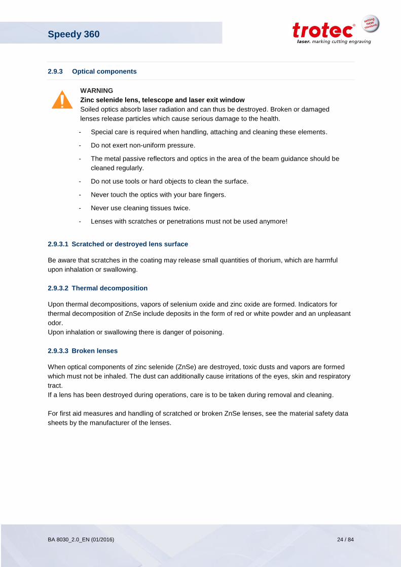
2.9.3 Optical components
WARNING
Zinc selenide lens, telescope and laser exit window
Soiled optics absorb laser radiation and can thus be destroyed. Broken or damaged
lenses release particles which cause serious damage to the health.
- Special care is required when handling, attaching and cleaning these elements.
- Do not exert non-uniform pressure.
- The metal passive reflectors and optics in the area of the beam guidance should be
cleaned regularly.
- Do not use tools or hard objects to clean the surface.
- Never touch the optics with your bare fingers.
- Never use cleaning tissues twice.
- Lenses with scratches or penetrations must not be used anymore!
2.9.3.1 Scratched or destroyed lens surface
Be aware that scratches in the coating may release small quantities of thorium, which are harmful
upon inhalation or swallowing.
2.9.3.2 Thermal decomposition
Upon thermal decompositions, vapors of selenium oxide and zinc oxide are formed. Indicators for
thermal decomposition of ZnSe include deposits in the form of red or white powder and an unpleasant
odor.
Upon inhalation or swallowing there is danger of poisoning.
2.9.3.3 Broken lenses
When optical components of zinc selenide (ZnSe) are destroyed, toxic dusts and vapors are formed
which must not be inhaled. The dust can additionally cause irritations of the eyes, skin and respiratory
tract.
If a lens has been destroyed during operations, care is to be taken during removal and cleaning.
For first aid measures and handling of scratched or broken ZnSe lenses, see the material safety data
sheets by the manufacturer of the lenses.
Speedy 360
BA 8030_2.0_EN (01/2016) 25 / 84
www.troteclaser.com
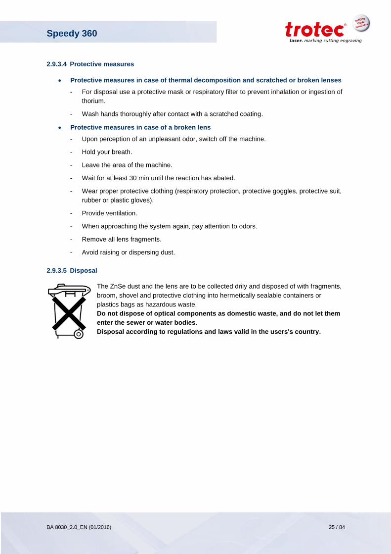
2.9.3.4 Protective measures
Protective measures in case of thermal decomposition and scratched or broken lenses
- For disposal use a protective mask or respiratory filter to prevent inhalation or ingestion of
thorium.
- Wash hands thoroughly after contact with a scratched coating.
Protective measures in case of a broken lens
- Upon perception of an unpleasant odor, switch off the machine.
- Hold your breath.
- Leave the area of the machine.
- Wait for at least 30 min until the reaction has abated.
- Wear proper protective clothing (respiratory protection, protective goggles, protective suit,
rubber or plastic gloves).
- Provide ventilation.
- When approaching the system again, pay attention to odors.
- Remove all lens fragments.
- Avoid raising or dispersing dust.
2.9.3.5 Disposal
The ZnSe dust and the lens are to be collected drily and disposed of with fragments,
broom, shovel and protective clothing into hermetically sealable containers or
plastics bags as hazardous waste.
Do not dispose of optical components as domestic waste, and do not let them
enter the sewer or water bodies.
Disposal according to regulations and laws valid in the users's country.
Speedy 360
BA 8030_2.0_EN (01/2016) 26 / 84
www.troteclaser.com
3 EC Declaration of Conformity
(Machine directive 2006/42/EC, appendix II A)
Manufacturer:
Trotec Laser GmbH.
Linzer Straße 156 A-4600 Wels
Authorized person for the compilation of technical documentation:
Gerhard KREMPL, Trotec Laser GmbH, Linzer Straße 156, A-4600 Wels
We hereby certify that
SPEEDY 360
Modell N° 8030 Speedy 360
in its conception, construction and form put into circulation by us is in accordance with all the relevant essential health and safety requirements of the EC machinery directive 2006/42/EEC.
Further guidelines/regulations applicable to the product:
2006/95/EC Low Voltage Directive
2004/108/EC EMC Guideline
Applied harmonized standards:
- EN ISO12100 Machine Safety
- EN 60335-1/2007 Safety of Household and Similar Appliances
- EN 55014-1/2006, EN 55014-2/1997 Electromagnetic Compatibility
- EN 60204-1 Machine Safety – Electr. Equipment
- EN 60825-1/2007, EN 60825-4/2006 and EN 60825-14/2006 Safety of Laser Equipment
- EN 55022/2008, EN 55024/2003 Electromagnetic Compatibility
Place, Date:
Wels, April 18th, 2015
Personal data of the signer:
Stephan FAZENY, Head of Research and Development
Signature:
Speedy 360
BA 8030_2.0_EN (01/2016) 27 / 84
www.troteclaser.com
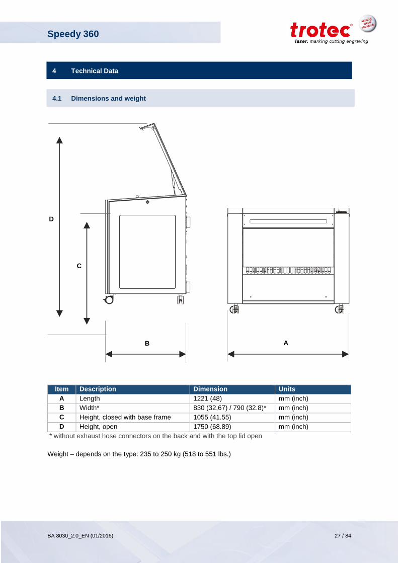
A B
C
D
4 Technical Data
4.1 Dimensions and weight
Item Description Dimension Units
A Length 1221 (48) mm (inch)
B Width* 830 (32,67) / 790 (32.8)* mm (inch)
C Height, closed with base frame 1055 (41.55) mm (inch)
D Height, open 1750 (68.89) mm (inch)
* without exhaust hose connectors on the back and with the top lid open
Weight – depends on the type: 235 to 250 kg (518 to 551 lbs.)
Speedy 360
BA 8030_2.0_EN (01/2016) 28 / 84
www.troteclaser.com
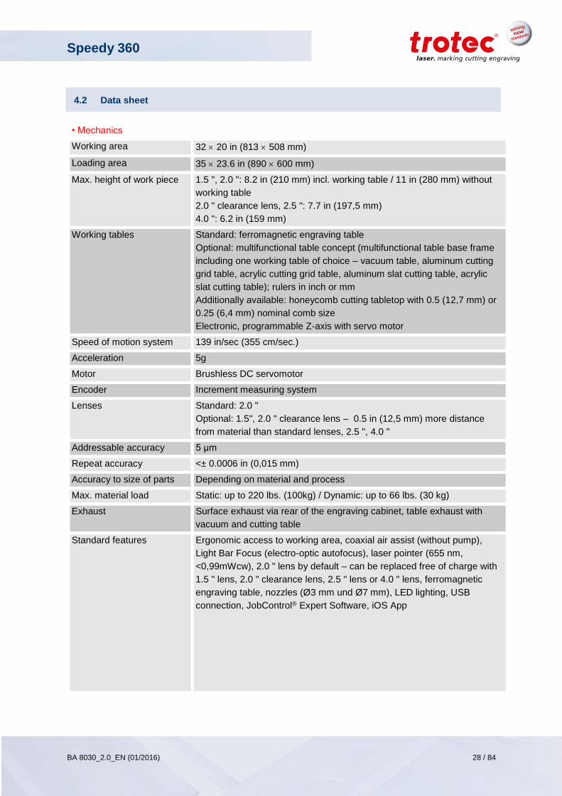
4.2 Data sheet
• Mechanics
Working area 32 20 in (813 508 mm)
Loading area 35 23.6 in (890 600 mm)
Max. height of work piece 1.5 ", 2.0 ": 8.2 in (210 mm) incl. working table / 11 in (280 mm) without
working table
2.0 " clearance lens, 2.5 ": 7.7 in (197,5 mm)
4.0 ": 6.2 in (159 mm)
Working tables Standard: ferromagnetic engraving table
Optional: multifunctional table concept (multifunctional table base frame
including one working table of choice – vacuum table, aluminum cutting
grid table, acrylic cutting grid table, aluminum slat cutting table, acrylic
slat cutting table); rulers in inch or mm
Additionally available: honeycomb cutting tabletop with 0.5 (12,7 mm) or
0.25 (6,4 mm) nominal comb size
Electronic, programmable Z-axis with servo motor
Speed of motion system 139 in/sec (355 cm/sec.)
Acceleration 5g
Motor Brushless DC servomotor
Encoder Increment measuring system
Lenses Standard: 2.0 "
Optional: 1.5", 2.0 " clearance lens – 0.5 in (12,5 mm) more distance
from material than standard lenses, 2.5 ", 4.0 "
Addressable accuracy 5 μm
Repeat accuracy <± 0.0006 in (0,015 mm)
Accuracy to size of parts Depending on material and process
Max. material load Static: up to 220 lbs. (100kg) / Dynamic: up to 66 lbs. (30 kg)
Exhaust Surface exhaust via rear of the engraving cabinet, table exhaust with
vacuum and cutting table
Standard features Ergonomic access to working area, coaxial air assist (without pump),
Light Bar Focus (electro-optic autofocus), laser pointer (655 nm,
<0,99mWcw), 2.0 " lens by default – can be replaced free of charge with
1.5 " lens, 2.0 " clearance lens, 2.5 " lens or 4.0 " lens, ferromagnetic
engraving table, nozzles (Ø3 mm und Ø7 mm), LED lighting, USB
connection, JobControl® Expert Software, iOS App
Speedy 360
BA 8030_2.0_EN (01/2016) 29 / 84
www.troteclaser.com
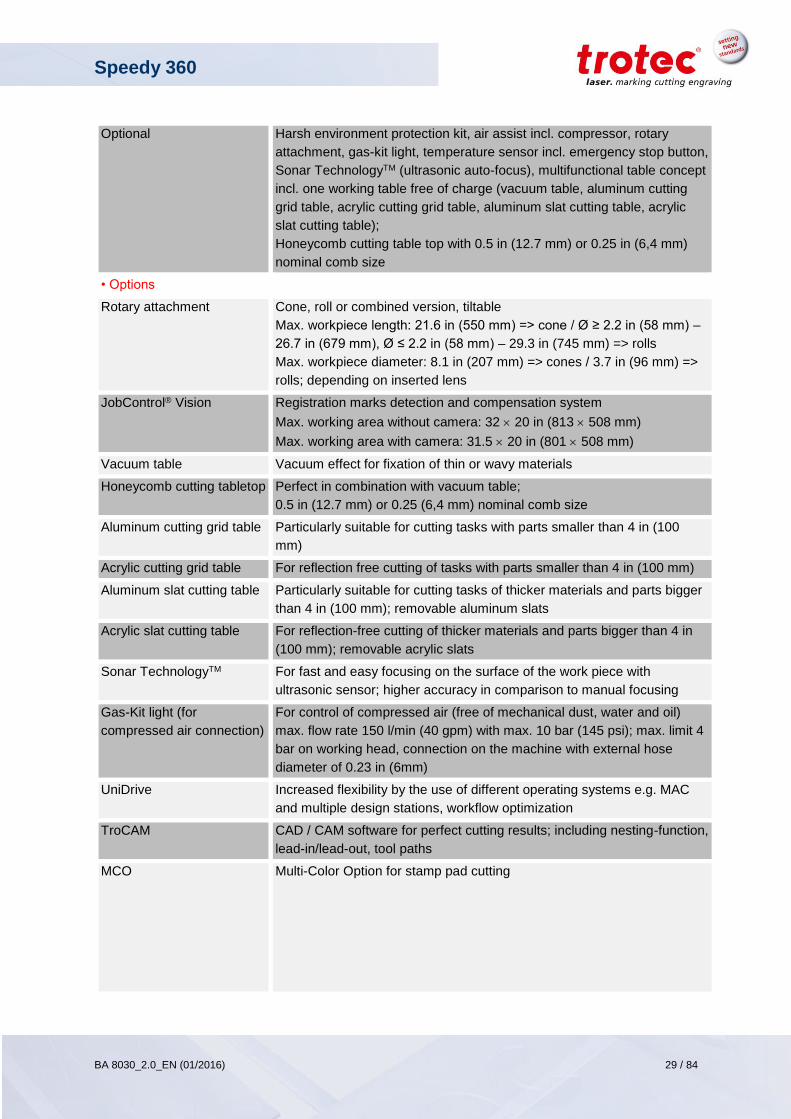
Optional Harsh environment protection kit, air assist incl. compressor, rotary
attachment, gas-kit light, temperature sensor incl. emergency stop button,
Sonar TechnologyTM (ultrasonic auto-focus), multifunctional table concept
incl. one working table free of charge (vacuum table, aluminum cutting
grid table, acrylic cutting grid table, aluminum slat cutting table, acrylic
slat cutting table);
Honeycomb cutting table top with 0.5 in (12.7 mm) or 0.25 in (6,4 mm)
nominal comb size
• Options
Rotary attachment Cone, roll or combined version, tiltable
Max. workpiece length: 21.6 in (550 mm) => cone / Ø ≥ 2.2 in (58 mm) –
26.7 in (679 mm), Ø ≤ 2.2 in (58 mm) – 29.3 in (745 mm) => rolls
Max. workpiece diameter: 8.1 in (207 mm) => cones / 3.7 in (96 mm) =>
rolls; depending on inserted lens
JobControl® Vision Registration marks detection and compensation system
Max. working area without camera: 32 20 in (813 508 mm)
Max. working area with camera: 31.5 20 in (801 508 mm)
Vacuum table Vacuum effect for fixation of thin or wavy materials
Honeycomb cutting tabletop Perfect in combination with vacuum table;
0.5 in (12.7 mm) or 0.25 (6,4 mm) nominal comb size
Aluminum cutting grid table Particularly suitable for cutting tasks with parts smaller than 4 in (100
mm)
Acrylic cutting grid table For reflection free cutting of tasks with parts smaller than 4 in (100 mm)
Aluminum slat cutting table Particularly suitable for cutting tasks of thicker materials and parts bigger
than 4 in (100 mm); removable aluminum slats
Acrylic slat cutting table For reflection-free cutting of thicker materials and parts bigger than 4 in
(100 mm); removable acrylic slats
Sonar TechnologyTM For fast and easy focusing on the surface of the work piece with
ultrasonic sensor; higher accuracy in comparison to manual focusing
Gas-Kit light (for
compressed air connection)
For control of compressed air (free of mechanical dust, water and oil)
max. flow rate 150 l/min (40 gpm) with max. 10 bar (145 psi); max. limit 4
bar on working head, connection on the machine with external hose
diameter of 0.23 in (6mm)
UniDrive Increased flexibility by the use of different operating systems e.g. MAC
and multiple design stations, workflow optimization
TroCAM CAD / CAM software for perfect cutting results; including nesting-function,
lead-in/lead-out, tool paths
MCO Multi-Color Option for stamp pad cutting
Speedy 360
BA 8030_2.0_EN (01/2016) 30 / 84
www.troteclaser.com
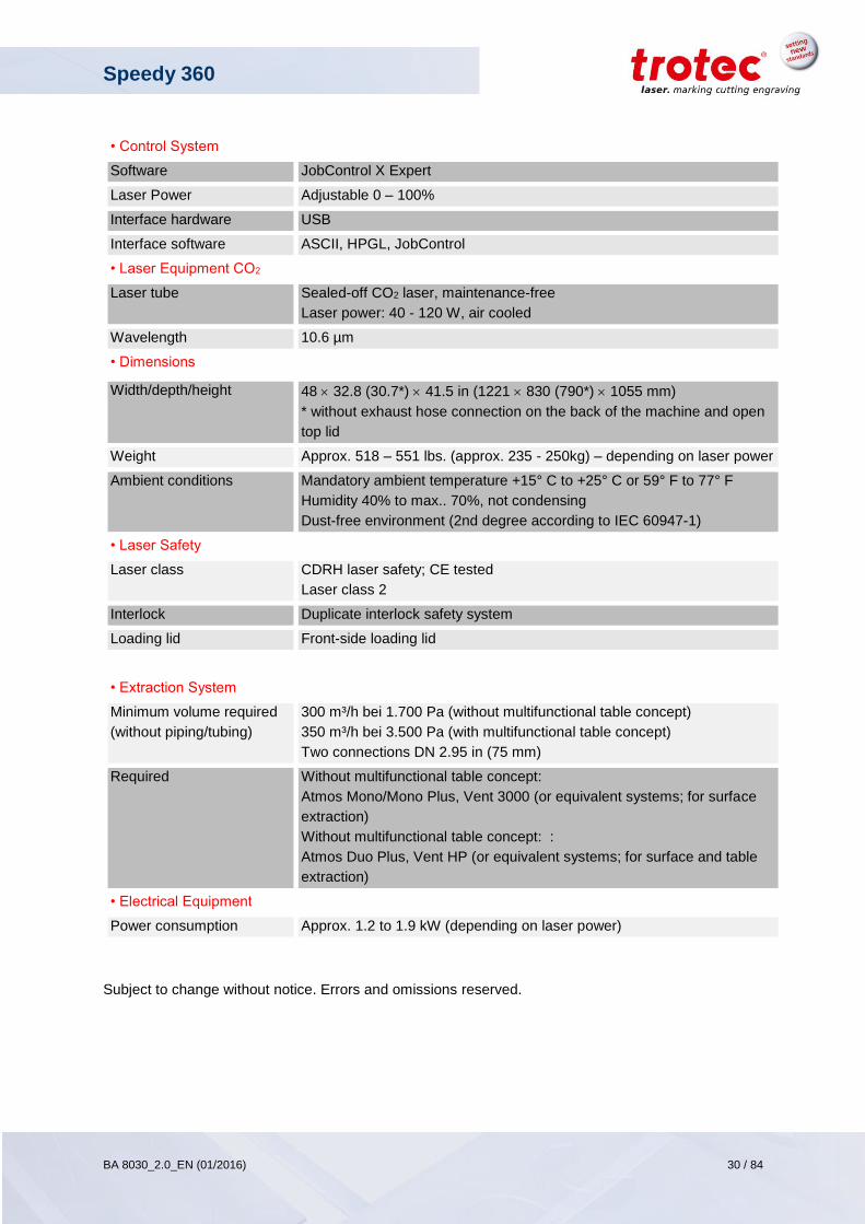
• Control System
Software JobControl X Expert
Laser Power Adjustable 0 – 100%
Interface hardware USB
Interface software ASCII, HPGL, JobControl
• Laser Equipment CO2
Laser tube Sealed-off CO2 laser, maintenance-free
Laser power: 40 - 120 W, air cooled
Wavelength 10.6 µm
• Dimensions
Width/depth/height 48 32.8 (30.7*) 41.5 in (1221 830 (790*) 1055 mm)
* without exhaust hose connection on the back of the machine and open
top lid
Weight Approx. 518 – 551 lbs. (approx. 235 - 250kg) – depending on laser power
Ambient conditions Mandatory ambient temperature +15° C to +25° C or 59° F to 77° F
Humidity 40% to max.. 70%, not condensing
Dust-free environment (2nd degree according to IEC 60947-1)
• Laser Safety
Laser class CDRH laser safety; CE tested
Laser class 2
Interlock Duplicate interlock safety system
Loading lid Front-side loading lid
• Extraction System
Minimum volume required
(without piping/tubing)
300 m³/h bei 1.700 Pa (without multifunctional table concept)
350 m³/h bei 3.500 Pa (with multifunctional table concept)
Two connections DN 2.95 in (75 mm)
Required Without multifunctional table concept:
Atmos Mono/Mono Plus, Vent 3000 (or equivalent systems; for surface
extraction)
Without multifunctional table concept: :
Atmos Duo Plus, Vent HP (or equivalent systems; for surface and table
extraction)
• Electrical Equipment
Power consumption Approx. 1.2 to 1.9 kW (depending on laser power)
Subject to change without notice. Errors and omissions reserved.
Speedy 360
BA 8030_2.0_EN (01/2016) 31 / 84
www.troteclaser.com
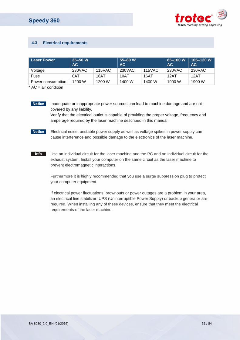
4.3 Electrical requirements
Laser Power 35–50 W AC
55–80 W AC
85–100 W AC
105–120 W AC
Voltage 230VAC 115VAC 230VAC 115VAC 230VAC 230VAC
Fuse 8AT 16AT 10AT 16AT 12AT 12AT
Power consumption 1200 W 1200 W 1400 W 1400 W 1900 W 1900 W
* AC = air condition
Inadequate or inappropriate power sources can lead to machine damage and are not
covered by any liability.
Verify that the electrical outlet is capable of providing the proper voltage, frequency and
amperage required by the laser machine described in this manual.
Electrical noise, unstable power supply as well as voltage spikes in power supply can
cause interference and possible damage to the electronics of the laser machine.
Use an individual circuit for the laser machine and the PC and an individual circuit for the
exhaust system. Install your computer on the same circuit as the laser machine to
prevent electromagnetic interactions.
Furthermore it is highly recommended that you use a surge suppression plug to protect
your computer equipment.
If electrical power fluctuations, brownouts or power outages are a problem in your area,
an electrical line stabilizer, UPS (Uninterruptible Power Supply) or backup generator are
required. When installing any of these devices, ensure that they meet the electrical
requirements of the laser machine.
Speedy 360
BA 8030_2.0_EN (01/2016) 32 / 84
www.troteclaser.com
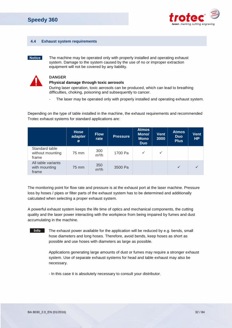
4.4 Exhaust system requirements
The machine may be operated only with properly installed and operating exhaust system. Damage to the system caused by the use of no or improper extraction equipment will not be covered by any liability.
DANGER
Physical damage through toxic aerosols
During laser operation, toxic aerosols can be produced, which can lead to breathing difficulties, choking, poisoning and subsequently to cancer.
- The laser may be operated only with properly installed and operating exhaust system.
Depending on the type of table installed in the machine, the exhaust requirements and recommended
Trotec exhaust systems for standard applications are:
Hose
adapter ø
Flow rate
Pressure
Atmos Mono/ Mono Duo
Vent 3000
Atmos Duo Plus
Vent HP
Standard table without mounting frame
75 mm 300 m³/h
1700 Pa
All table variants with mounting frame
75 mm 350 m³/h
3500 Pa
The monitoring point for flow rate and pressure is at the exhaust port at the laser machine. Pressure
loss by hoses / pipes or filter parts of the exhaust system has to be determined and additionally
calculated when selecting a proper exhaust system.
A powerful exhaust system keeps the life time of optics and mechanical components, the cutting
quality and the laser power interacting with the workpiece from being impaired by fumes and dust
accumulating in the machine.
The exhaust power available for the application will be reduced by e.g. bends, small
hose diameters and long hoses. Therefore, avoid bends, keep hoses as short as
possible and use hoses with diameters as large as possible.
Applications generating large amounts of dust or fumes may require a stronger exhaust
system. Use of separate exhaust systems for head and table exhaust may also be
necessary.
- In this case it is absolutely necessary to consult your distributor.
Speedy 360
BA 8030_2.0_EN (01/2016) 33 / 84
www.troteclaser.com
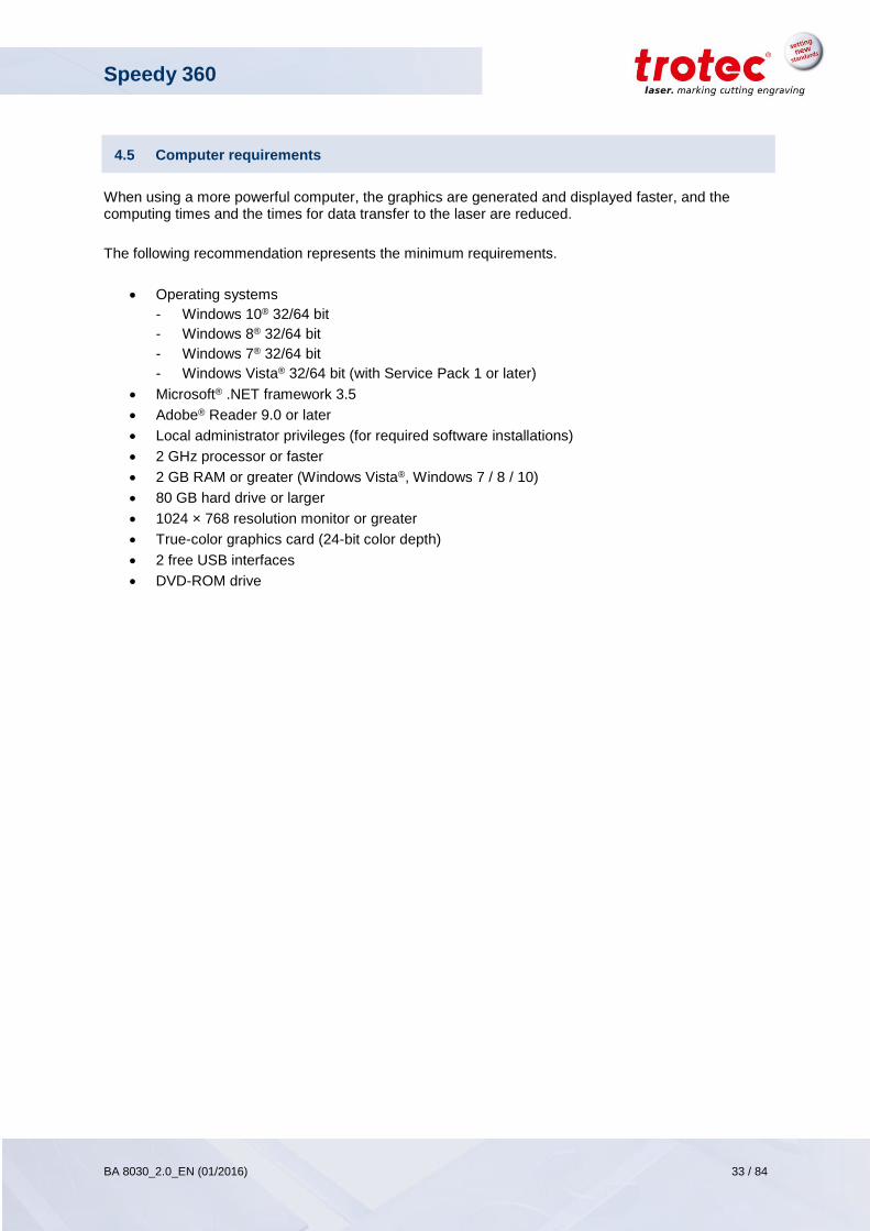
4.5 Computer requirements
When using a more powerful computer, the graphics are generated and displayed faster, and the computing times and the times for data transfer to the laser are reduced.
The following recommendation represents the minimum requirements.
Operating systems
- Windows 10® 32/64 bit
- Windows 8® 32/64 bit
- Windows 7® 32/64 bit
- Windows Vista® 32/64 bit (with Service Pack 1 or later)
Microsoft® .NET framework 3.5
Adobe® Reader 9.0 or later
Local administrator privileges (for required software installations)
2 GHz processor or faster
2 GB RAM or greater (Windows Vista®, Windows 7 / 8 / 10)
80 GB hard drive or larger
1024 × 768 resolution monitor or greater
True-color graphics card (24-bit color depth)
2 free USB interfaces
DVD-ROM drive
Speedy 360
BA 8030_2.0_EN (01/2016) 34 / 84
www.troteclaser.com
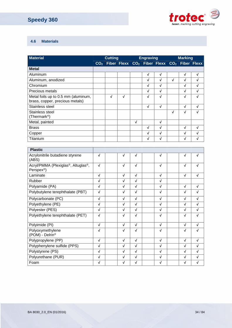
4.6 Materials
Material Cutting Engraving Marking
CO2 Fiber Flexx CO2 Fiber Flexx CO2 Fiber Flexx
Metal
Aluminum √ √ √ √
Aluminum, anodized √ √ √ √ √
Chromium √ √ √ √
Precious metals √ √ √ √
Metal foils up to 0.5 mm (aluminum, brass, copper, precious metals)
√ √ √ √ √ √
Stainless steel √ √ √ √
Stainless steel (Thermark®)
√ √ √
Metal, painted √ √
Brass √ √ √ √
Copper √ √ √ √
Titanium √ √ √ √
Plastic
Acrylonitrile butadiene styrene (ABS)
√ √ √ √ √ √
Acryl/PMMA (Plexiglas®, Altuglas®, Perspex®)
√ √ √ √ √ √
Laminate √ √ √ √ √ √
Rubber √ √ √ √
Polyamide (PA) √ √ √ √ √ √
Polybutylene terephthalate (PBT) √ √ √ √ √ √
Polycarbonate (PC) √ √ √ √ √ √
Polyethylene (PE) √ √ √ √ √ √
Polyester (PES) √ √ √ √ √ √
Polyethylene terephthalate (PET) √ √ √ √ √ √
Polyimide (PI) √ √ √ √ √ √
Polyoxymethylene (POM) - Delrin®
√ √ √ √ √ √
Polypropylene (PP) √ √ √ √ √ √
Polyphenylene sulfide (PPS) √ √ √ √ √ √
Polystyrene (PS) √ √ √ √ √ √
Polyurethane (PUR) √ √ √ √ √ √
Foam √ √ √ √ √ √
Speedy 360
BA 8030_2.0_EN (01/2016) 35 / 84
www.troteclaser.com
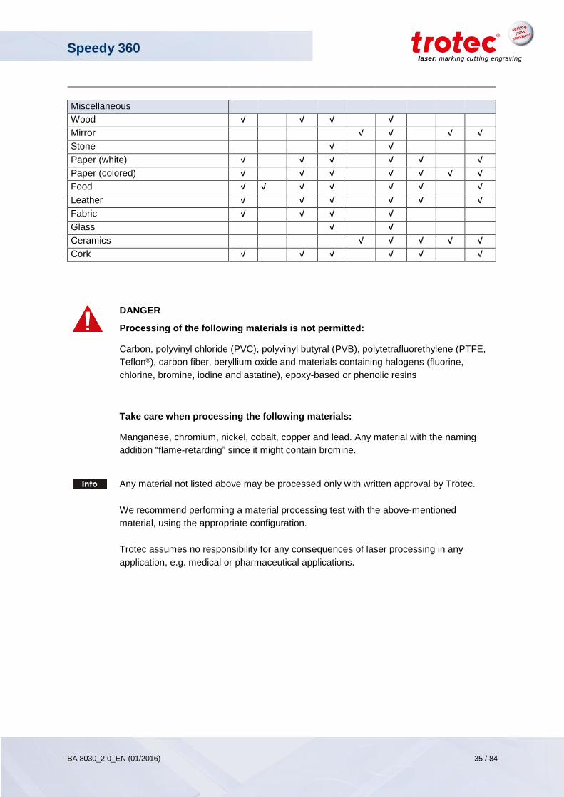
Miscellaneous
Wood √ √ √ √
Mirror √ √ √ √
Stone √ √
Paper (white) √ √ √ √ √ √
Paper (colored) √ √ √ √ √ √ √
Food √ √ √ √ √ √ √
Leather √ √ √ √ √ √
Fabric √ √ √ √
Glass √ √
Ceramics √ √ √ √ √
Cork √ √ √ √ √ √
DANGER
Processing of the following materials is not permitted:
Carbon, polyvinyl chloride (PVC), polyvinyl butyral (PVB), polytetrafluorethylene (PTFE,
Teflon®), carbon fiber, beryllium oxide and materials containing halogens (fluorine,
chlorine, bromine, iodine and astatine), epoxy-based or phenolic resins
Take care when processing the following materials:
Manganese, chromium, nickel, cobalt, copper and lead. Any material with the naming
addition “flame-retarding” since it might contain bromine.
Any material not listed above may be processed only with written approval by Trotec.
We recommend performing a material processing test with the above-mentioned
material, using the appropriate configuration.
Trotec assumes no responsibility for any consequences of laser processing in any
application, e.g. medical or pharmaceutical applications.
Speedy 360
BA 8030_2.0_EN (01/2016) 36 / 84
www.troteclaser.com
13
15
14
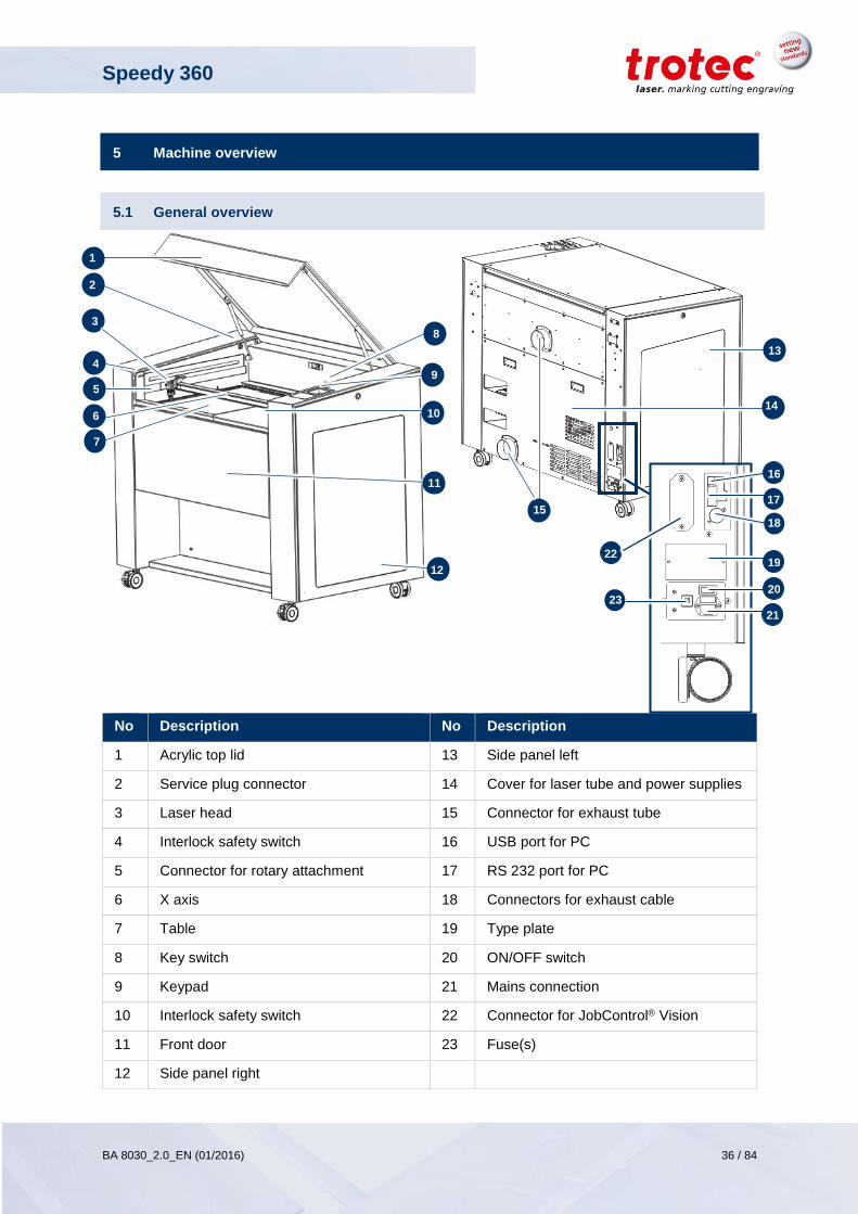
5 Machine overview
5.1 General overview
No Description No Description
1 Acrylic top lid 13 Side panel left
2 Service plug connector 14 Cover for laser tube and power supplies
3 Laser head 15 Connector for exhaust tube
4 Interlock safety switch 16 USB port for PC
5 Connector for rotary attachment 17 RS 232 port for PC
6 X axis 18 Connectors for exhaust cable
7 Table 19 Type plate
8 Key switch 20 ON/OFF switch
9 Keypad 21 Mains connection
10 Interlock safety switch 22 Connector for JobControl® Vision
11 Front door 23 Fuse(s)
12 Side panel right
12
1
5
3 8
11
2
4
4
6
7
10
17
16
18
19
20
21
22
23
9
Speedy 360
BA 8030_2.0_EN (01/2016) 37 / 84
www.troteclaser.com
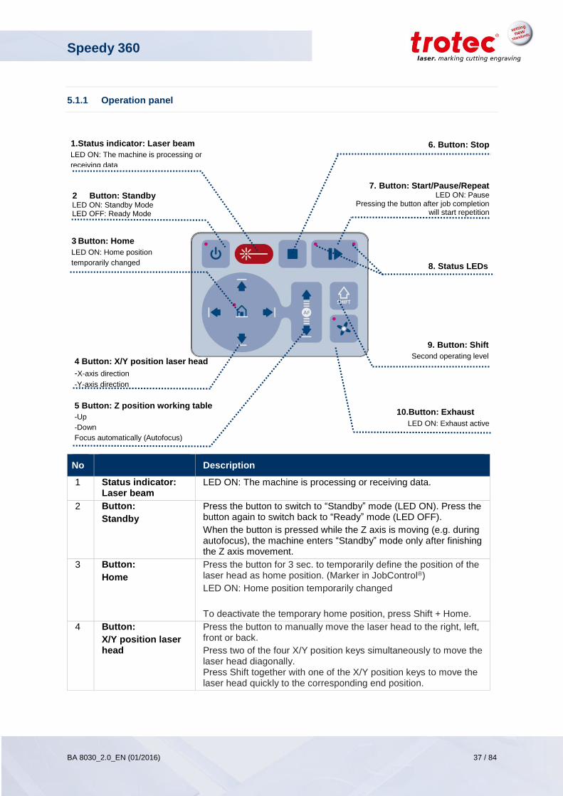
5.1.1 Operation panel
No Description
1 Status indicator: Laser beam
LED ON: The machine is processing or receiving data.
2 Button:
Standby
Press the button to switch to “Standby” mode (LED ON). Press the button again to switch back to “Ready” mode (LED OFF).
When the button is pressed while the Z axis is moving (e.g. during autofocus), the machine enters “Standby” mode only after finishing the Z axis movement.
3 Button:
Home
Press the button for 3 sec. to temporarily define the position of the laser head as home position. (Marker in JobControl®)
LED ON: Home position temporarily changed
To deactivate the temporary home position, press Shift + Home.
4 Button:
X/Y position laser head
Press the button to manually move the laser head to the right, left, front or back.
Press two of the four X/Y position keys simultaneously to move the laser head diagonally. Press Shift together with one of the X/Y position keys to move the laser head quickly to the corresponding end position.
1.Status indicator: Laser beam
LED ON: The machine is processing or
receiving data
5 Button: Z position working table
-Up
-Down
Focus automatically (Autofocus)
3 Button: Home
LED ON: Home position
temporarily changed
2 Button: Standby LED ON: Standby Mode LED OFF: Ready Mode
4 Button: X/Y position laser head
-X-axis direction
-Y-axis direction
9. Button: Shift
Second operating level
10.Button: Exhaust
LED ON: Exhaust active
8. Status LEDs
7. Button: Start/Pause/Repeat
LED ON: Pause Pressing the button after job completion
will start repetition
6. Button: Stop
Speedy 360
BA 8030_2.0_EN (01/2016) 38 / 84
www.troteclaser.com
5 Button:
Z position working table
Press the button to manually move the working table up or down.
Press Shift together with one of the Z position keys to move the laser head to the corresponding end position. The Z axis movement can be stopped by pressing any of the Z axis keys.
With light sensor or Sonar Technology™: Press both Z position keys simultaneously to move up the working table automatically to the right focus position.
To stop the movement press any Z position key. For further information see chapter “Focusing”.
6 Button: Stop Press the button to stop the current working process.
7 Button:
Start/Pause/Repeat
Press the button to start the job which is currently on the plate in JobControl®.
If a job is currently being processed, press the button to pause the job (LED ON). Press the button again to continue the interrupted working process (LED OFF).
Press the button after a job was finished to repeat the actual job positioned on the plate in JobControl®.
8 Status LEDs Indicates the current status of the machine:
Green, flashing slowly (0.5 Hz) Machine is ready
All covers closed
Green, flashing fast (2 Hz) Cover is open
Blue and green, permanent Data available
“Pause” mode
Green, permanent Receiving or processing
data
9 Button: Shift For second operating level. Press the button together with any of the following keys to activate the following functions:
Shift functions:
Shift + Exhaust Air assist on/off
Shift + Z position working table
Laser head moves quickly to
corresponding end position
Shift + Standby Keypad locked/unlocked
Shift + Stop LED light on/off
Shift + UP Work table moves up to autofocus
position
Shift + DOWN Work table moves to the lowest
position
Shift + Home Deactivated temporary home
position
10 Button:
Exhaust
Press the button to switch the exhaust on or off.
LED ON: Exhaust activated
LED OFF: Exhaust deactivated
After completing the engraving process, the exhaust system can be switched off only after a few seconds more (follow-up time).
Speedy 360
BA 8030_2.0_EN (01/2016) 39 / 84
www.troteclaser.com
5.1.1.1 Keyboard shortcuts
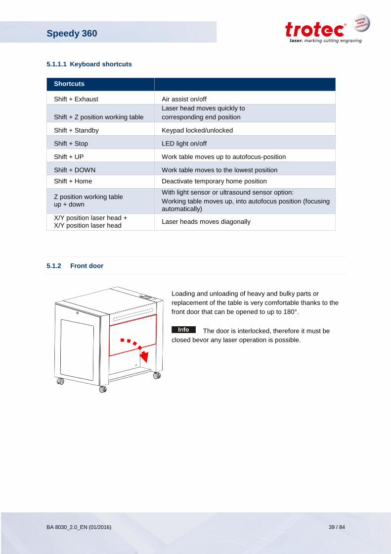
5.1.2 Front door
Loading and unloading of heavy and bulky parts or
replacement of the table is very comfortable thanks to the
front door that can be opened to up to 180°.
The door is interlocked, therefore it must be
closed bevor any laser operation is possible.
Shortcuts
Shift + Exhaust Air assist on/off
Shift + Z position working table
Laser head moves quickly to
corresponding end position
Shift + Standby Keypad locked/unlocked
Shift + Stop LED light on/off
Shift + UP Work table moves up to autofocus-position
Shift + DOWN Work table moves to the lowest position
Shift + Home Deactivate temporary home position
Z position working table up + down
With light sensor or ultrasound sensor option:
Working table moves up, into autofocus position (focusing automatically)
X/Y position laser head + X/Y position laser head
Laser heads moves diagonally
Speedy 360
BA 8030_2.0_EN (01/2016) 40 / 84
www.troteclaser.com
5.2 Tables (multifunctional table concept)
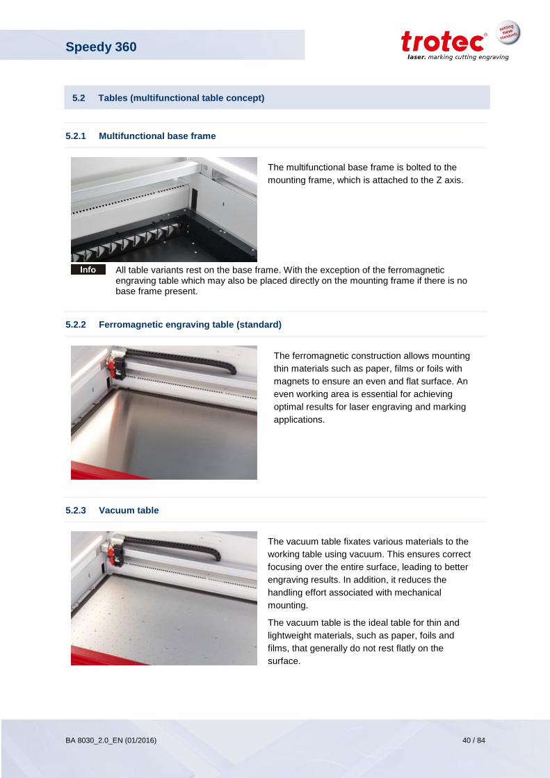
5.2.1 Multifunctional base frame
The multifunctional base frame is bolted to the
mounting frame, which is attached to the Z axis.
All table variants rest on the base frame. With the exception of the ferromagnetic engraving table which may also be placed directly on the mounting frame if there is no base frame present.
5.2.2 Ferromagnetic engraving table (standard)
The ferromagnetic construction allows mounting
thin materials such as paper, films or foils with
magnets to ensure an even and flat surface. An
even working area is essential for achieving
optimal results for laser engraving and marking
applications.
5.2.3 Vacuum table
The vacuum table fixates various materials to the
working table using vacuum. This ensures correct
focusing over the entire surface, leading to better
engraving results. In addition, it reduces the
handling effort associated with mechanical
mounting.
The vacuum table is the ideal table for thin and
lightweight materials, such as paper, foils and
films, that generally do not rest flatly on the
surface.
Speedy 360
BA 8030_2.0_EN (01/2016) 41 / 84
www.troteclaser.com
5.2.4 Cutting tables
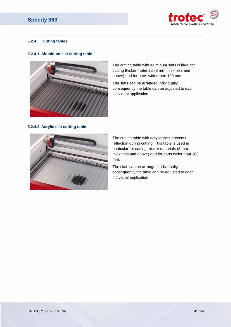
5.2.4.1 Aluminum slat cutting table
The cutting table with aluminum slats is ideal for
cutting thicker materials (8 mm thickness and
above) and for parts wider than 100 mm.
The slats can be arranged individually,
consequently the table can be adjusted to each
individual application.
5.2.4.2 Acrylic slat cutting table
The cutting table with acrylic slats prevents
reflection during cutting. This table is used in
particular for cutting thicker materials (8 mm
thickness and above) and for parts wider than 100
mm.
The slats can be arranged individually,
consequently the table can be adjusted to each
individual application.
Speedy 360
BA 8030_2.0_EN (01/2016) 42 / 84
www.troteclaser.com
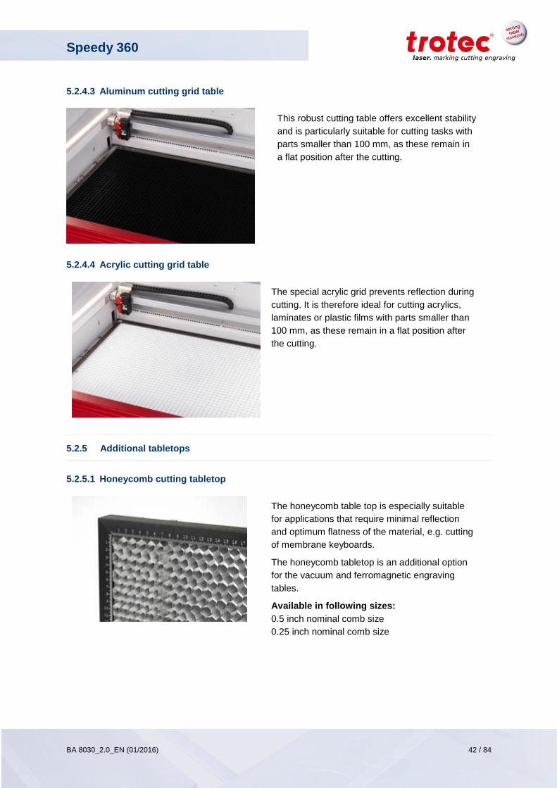
5.2.4.3 Aluminum cutting grid table
This robust cutting table offers excellent stability
and is particularly suitable for cutting tasks with
parts smaller than 100 mm, as these remain in
a flat position after the cutting.
5.2.4.4 Acrylic cutting grid table
The special acrylic grid prevents reflection during
cutting. It is therefore ideal for cutting acrylics,
laminates or plastic films with parts smaller than
100 mm, as these remain in a flat position after
the cutting.
5.2.5 Additional tabletops
5.2.5.1 Honeycomb cutting tabletop
The honeycomb table top is especially suitable
for applications that require minimal reflection
and optimum flatness of the material, e.g. cutting
of membrane keyboards.
The honeycomb tabletop is an additional option
for the vacuum and ferromagnetic engraving
tables.
Available in following sizes:
0.5 inch nominal comb size
0.25 inch nominal comb size
Speedy 360
BA 8030_2.0_EN (01/2016) 43 / 84
www.troteclaser.com
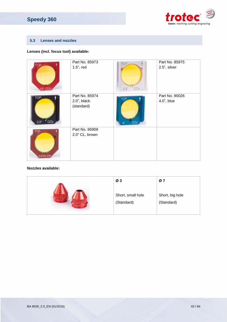
5.3 Lenses and nozzles
Lenses (incl. focus tool) available:
Part No. 85973
1.5”, red
Part No. 85975
2.5”, silver
Part No. 85974
2.0”, black
(standard)
Part No. 90026
4.0”, blue
Part No. 95909
2.0” CL, brown
Nozzles available:
Ø 3
Short, small hole
(Standard)
Ø 7
Short, big hole
(Standard)
Speedy 360
BA 8030_2.0_EN (01/2016) 44 / 84
www.troteclaser.com
6 Transport, packaging and storage
6.1 Safety notes
WARNING Risk of injury There is risk of injury from falling parts during transport, loading and unloading of the machine. - Follow the safety instructions.
Observe the safety instructions to avoid damage to the machine from improper handling during
transport:
Always move the machine with utmost care and attention.
Take the machine’s center of gravity into account when transporting it (minimize the risk of tipping
over).
Observe the packaging symbols (e.g. transport the machine only in upright position).
Take measures to prevent the machine from slipping sideways.
Transport the machine as carefully as possible in order to prevent damage.
Avoid vibrations.
When transporting the machine overseas, the device must be packaged airtight and protected
against corrosion.
When transporting outdoors, transport only in vehicles with roof or sufficient weather protection.
Protect the machine against transportation damage using straps and inserts, and leave sufficient
gaps to other transported items.
Do not place any other loads or items on the machine or machine components.
6.2 Transport and unloading
Unless otherwise agreed, the machine is delivered in a wooden crate that contains the laser machine
and additional accessories. Transport the machine only in its original packaging.
During transport the transport case can slip, tip or fall over, if not properly secured
6.2.1 Required tools
Unloading Transport
Type forklift pallet truck
Speedy 360
BA 8030_2.0_EN (01/2016) 45 / 84
www.troteclaser.com
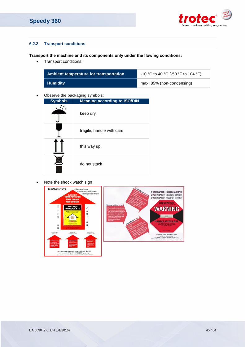
6.2.2 Transport conditions
Transport the machine and its components only under the flowing conditions:
Transport conditions:
Ambient temperature for transportation -10 °C to 40 °C (-50 °F to 104 °F)
Humidity max. 85% (non-condensing)
Observe the packaging symbols:
Symbols Meaning according to ISO/DIN
keep dry
fragile, handle with care
this way up
do not stack
Note the shock watch sign
Speedy 360
BA 8030_2.0_EN (01/2016) 46 / 84
www.troteclaser.com
6.3 Storage and storage conditions
Store packed items only under the following conditions:
1. Storage conditions:
Storage temperature: +0 °C to 30 °C (32 °F to 86 °F)
Relative humidity: max. 60%
2. Keep the machine sealed in its packaging until it is assembled/installed.
3. The storage location must be dry, free of dust, caustic materials, vapors and combustible
materials.
4. Store in a storage room or packaged with adequate weather protection.
5. Avoid exposure of the machine to shocks or vibrations.
6. Avoid extreme temperature fluctuations.
7. Take particular care when packing away electronic components.
8. When storing for a longer period, apply a coat of oil to all bare-metal machine parts. Regularly
check the overall condition of all parts and of the packaging.
Speedy 360
BA 8030_2.0_EN (01/2016) 47 / 84
www.troteclaser.com
6.4 Unpacking the machine
Only trained and authorized personnel are permitted to transport and unpack the machine.
To avoid falling off of any wooden parts or tipping of the machine, be very careful when opening the transport case.
Keep the original packaging case, in case the machine needs to be relocated or transported over longer distances. Dispose all waste according to the applicable waste disposal law.
The lens unit should be unpacked only after installation of the machine. The lenses are high-quality optical components which must be kept clean in order to ensure optimum marking results. Never touch the lenses with bare fingers!
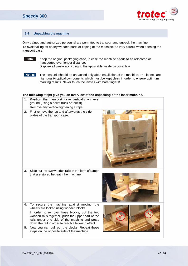
The following steps give you an overview of the unpacking of the laser machine.
1. Position the transport case vertically on level ground (using a pallet truck or forklift).
Remove any vertical tightening straps.
2. First remove the top and afterwards the side plates of the transport case.
3. Slide out the two wooden rails in the form of ramps that are stored beneath the machine.
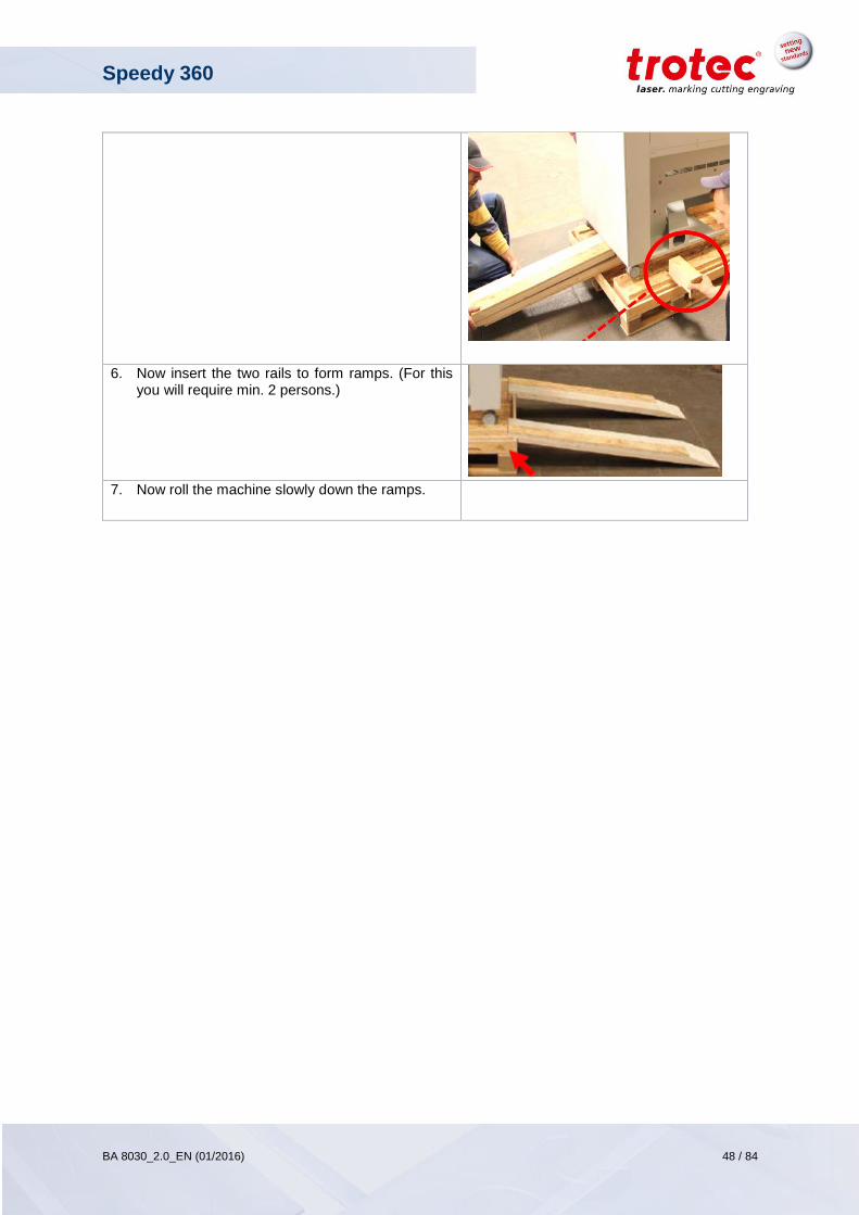
4. To secure the machine against moving, the wheels are locked using wooden blocks.
In order to remove those blocks, put the two wooden rails together, push the upper part of the rails under one side of the machine and press down the rail in order to reach a levering effect.
5. Now you can pull out the blocks. Repeat those steps on the opposite side of the machine.
Speedy 360
BA 8030_2.0_EN (01/2016) 48 / 84
www.troteclaser.com
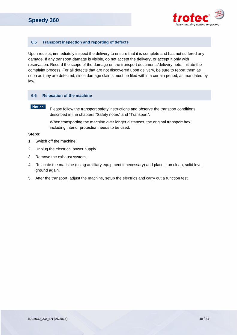
6. Now insert the two rails to form ramps. (For this you will require min. 2 persons.)
7. Now roll the machine slowly down the ramps.
Speedy 360
BA 8030_2.0_EN (01/2016) 49 / 84
www.troteclaser.com
6.5 Transport inspection and reporting of defects
Upon receipt, immediately inspect the delivery to ensure that it is complete and has not suffered any
damage. If any transport damage is visible, do not accept the delivery, or accept it only with
reservation. Record the scope of the damage on the transport documents/delivery note. Initiate the
complaint process. For all defects that are not discovered upon delivery, be sure to report them as
soon as they are detected, since damage claims must be filed within a certain period, as mandated by
law.
6.6 Relocation of the machine
Please follow the transport safety instructions and observe the transport conditions
described in the chapters “Safety notes” and “Transport”.
When transporting the machine over longer distances, the original transport box
including interior protection needs to be used.
Steps:
1. Switch off the machine.
2. Unplug the electrical power supply.
3. Remove the exhaust system.
4. Relocate the machine (using auxiliary equipment if necessary) and place it on clean, solid level
ground again.
5. After the transport, adjust the machine, setup the electrics and carry out a function test.
Speedy 360
BA 8030_2.0_EN (01/2016) 50 / 84
www.troteclaser.com
7 Setup and installation
7.1 Safety notes
WARNING
Improper assembly or setup can cause serious injury or damage. For this reason, this
work may be carried out only by authorized, trained personnel who are familiar with how
to operate the machine and in strict observance of all safety instructions.
An incomplete, faulty or damaged machine can lead to serious physical injury or property
damage. Assemble and install the machine only if the machine and its parts are complete
and intact.
Operate the machine only in ambient temperatures from +15 °C to +25 °C (+59 °F to
+77 °F). Relative humidity must not exceed 40% – 70% (non-condensing). If the
instructions are not followed, damage may occur during operation.
If the system has been subject to significant temperature fluctuations, it must be brought
back to room temperature before being commissioned.
A laser system consists of high-quality electrical and optical components. Mechanical
stresses, vibrations and impacts must always be avoided.
WARNING
Work on electrical fittings may be carried out only by qualified personnel and in strict observance of the safety notes.
Note the following:
Ensure that there is sufficient distance to neighboring machines, walls or other fixed equipment.
Keep the work area orderly and clean.
Before assembling and installing the machine, check it to make sure it is complete and in good
condition.
Speedy 360
BA 8030_2.0_EN (01/2016) 51 / 84
www.troteclaser.com
7.2 Operating environment
Installation side requirements:
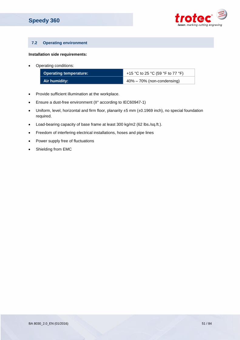
Operating conditions:
Operating temperature: +15 °C to 25 °C (59 °F to 77 °F)
Air humidity: 40% – 70% (non-condensing)
Provide sufficient illumination at the workplace.
Ensure a dust-free environment (II° according to IEC60947-1)
Uniform, level, horizontal and firm floor, planarity ±5 mm (±0.1969 inch), no special foundation
required.
Load-bearing capacity of base frame at least 300 kg/m2 (62 lbs./sq.ft.).
Freedom of interfering electrical installations, hoses and pipe lines
Power supply free of fluctuations
Shielding from EMC
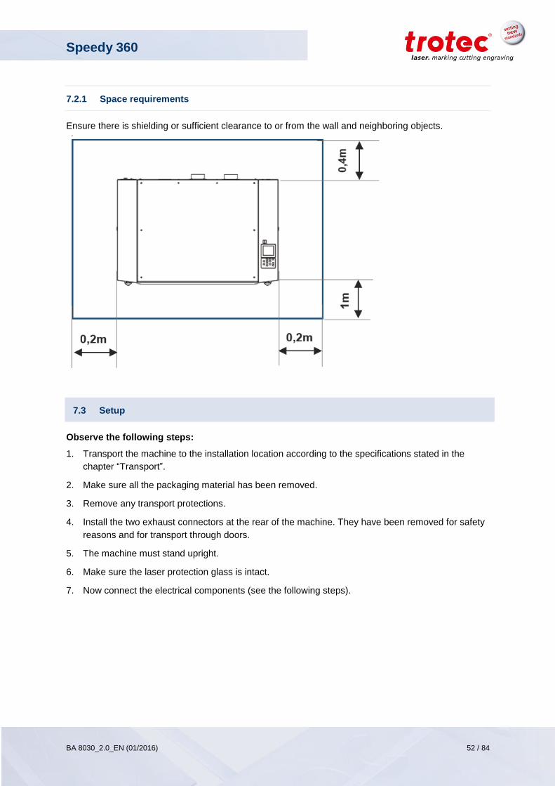
Speedy 360
BA 8030_2.0_EN (01/2016) 52 / 84
www.troteclaser.com
7.2.1 Space requirements
Ensure there is shielding or sufficient clearance to or from the wall and neighboring objects.
7.3 Setup
Observe the following steps:
1. Transport the machine to the installation location according to the specifications stated in the
chapter “Transport”.
2. Make sure all the packaging material has been removed.
3. Remove any transport protections.
4. Install the two exhaust connectors at the rear of the machine. They have been removed for safety
reasons and for transport through doors.
5. The machine must stand upright.
6. Make sure the laser protection glass is intact.
7. Now connect the electrical components (see the following steps).
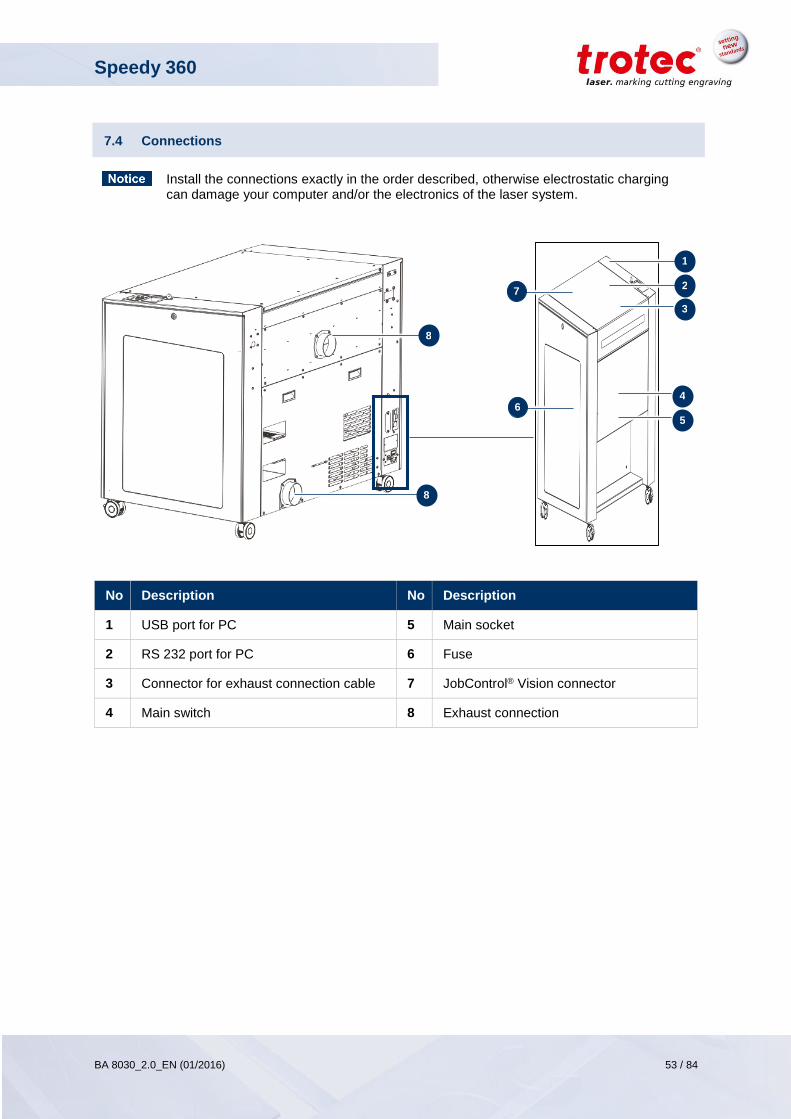
Speedy 360
BA 8030_2.0_EN (01/2016) 53 / 84
www.troteclaser.com
7.4 Connections
Install the connections exactly in the order described, otherwise electrostatic charging can damage your computer and/or the electronics of the laser system.
No Description No Description
1 USB port for PC 5 Main socket
2 RS 232 port for PC 6 Fuse
3 Connector for exhaust connection cable 7 JobControl® Vision connector
4 Main switch 8 Exhaust connection
1
2
3
4
5
6
7
8
8
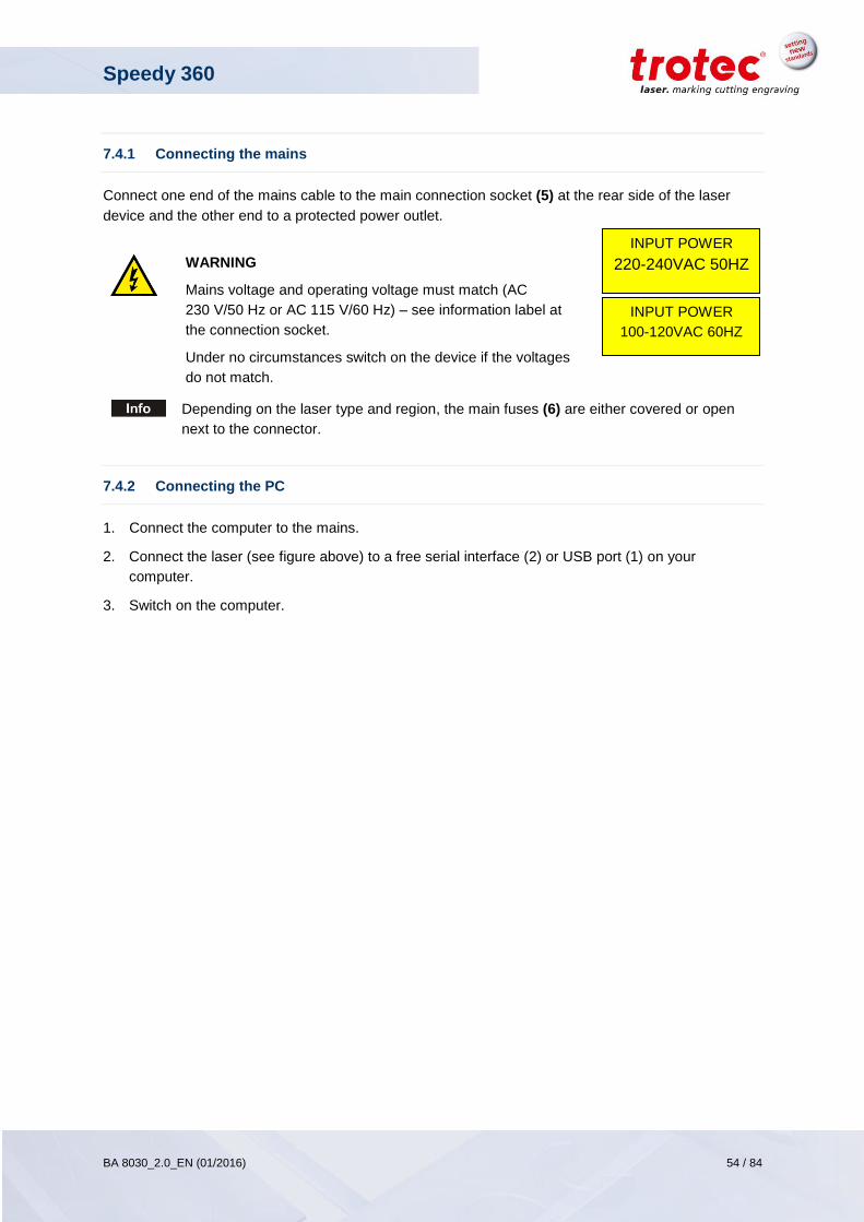
Speedy 360
BA 8030_2.0_EN (01/2016) 54 / 84
www.troteclaser.com
7.4.1 Connecting the mains
Connect one end of the mains cable to the main connection socket (5) at the rear side of the laser
device and the other end to a protected power outlet.
WARNING
Mains voltage and operating voltage must match (AC
230 V/50 Hz or AC 115 V/60 Hz) – see information label at
the connection socket.
Under no circumstances switch on the device if the voltages
do not match.
Depending on the laser type and region, the main fuses (6) are either covered or open
next to the connector.
7.4.2 Connecting the PC
1. Connect the computer to the mains.
2. Connect the laser (see figure above) to a free serial interface (2) or USB port (1) on your
computer.
3. Switch on the computer.
INPUT POWER
220-240VAC 50HZ
INPUT POWER
100-120VAC 60HZ
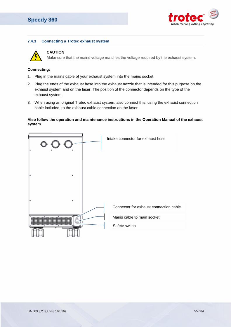
Speedy 360
BA 8030_2.0_EN (01/2016) 55 / 84
www.troteclaser.com
7.4.3 Connecting a Trotec exhaust system
CAUTION
Make sure that the mains voltage matches the voltage required by the exhaust system.
Connecting:
1. Plug in the mains cable of your exhaust system into the mains socket.
2. Plug the ends of the exhaust hose into the exhaust nozzle that is intended for this purpose on the
exhaust system and on the laser. The position of the connector depends on the type of the
exhaust system.
3. When using an original Trotec exhaust system, also connect this, using the exhaust connection
cable included, to the exhaust cable connection on the laser.
Also follow the operation and maintenance instructions in the Operation Manual of the exhaust system.
Intake connector for exhaust hose
Connector for exhaust connection cable
(3)
Mains cable to main socket
(3)
Safety switch
(3)
Speedy 360
BA 8030_2.0_EN (01/2016) 56 / 84
www.troteclaser.com
8 Operation
Improper operation may lead to severe physical injury or property damage. For this reason, work may be carried out only by authorized, trained personnel who are familiar with how to operate the machine and in strict observance of all safety instructions.
8.1 Before operation
Before commissioning, the following points need to be checked:
Check the machine to ensure that it is in technically flawless condition and complete.
Keep work area orderly and clean. Source of accidents!
Ensure that the optical components are free from dust and dirt.
Activate the extraction system.
Ensure that the electrical installation is complete and the input voltage is correct.
Check the environmental conditions using the technical specification.
Familiarize yourself with the laser safety regulations.
Fulfil all laser safety requirements.
The system may be switched on only when all provisions for complying with laser safety have
been checked by an authorized person and confirmed to have met the standards.
8.2 Software
For information on how to use the software, please read the accompanying software manual.
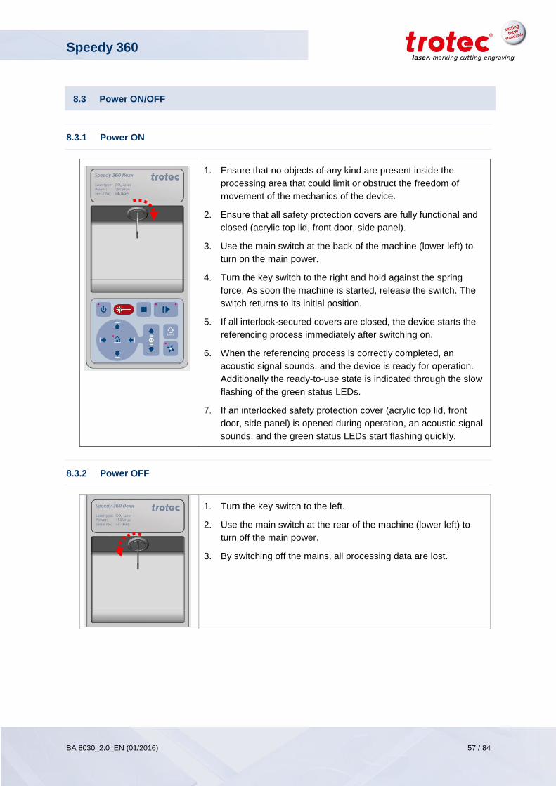
Speedy 360
BA 8030_2.0_EN (01/2016) 57 / 84
www.troteclaser.com
8.3 Power ON/OFF
8.3.1 Power ON
1. Ensure that no objects of any kind are present inside the
processing area that could limit or obstruct the freedom of
movement of the mechanics of the device.
2. Ensure that all safety protection covers are fully functional and
closed (acrylic top lid, front door, side panel).
3. Use the main switch at the back of the machine (lower left) to
turn on the main power.
4. Turn the key switch to the right and hold against the spring
force. As soon the machine is started, release the switch. The
switch returns to its initial position.
5. If all interlock-secured covers are closed, the device starts the
referencing process immediately after switching on.
6. When the referencing process is correctly completed, an
acoustic signal sounds, and the device is ready for operation.
Additionally the ready-to-use state is indicated through the slow
flashing of the green status LEDs.
7. If an interlocked safety protection cover (acrylic top lid, front
door, side panel) is opened during operation, an acoustic signal
sounds, and the green status LEDs start flashing quickly.
8.3.2 Power OFF
1. Turn the key switch to the left.
2. Use the main switch at the rear of the machine (lower left) to
turn off the main power.
3. By switching off the mains, all processing data are lost.
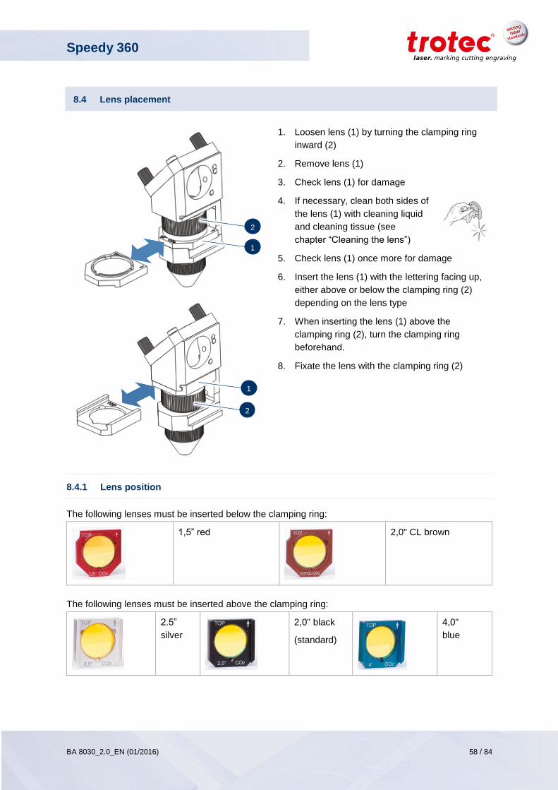
Speedy 360
BA 8030_2.0_EN (01/2016) 58 / 84
www.troteclaser.com
8.4 Lens placement
1. Loosen lens (1) by turning the clamping ring
inward (2)
2. Remove lens (1)
3. Check lens (1) for damage
4. If necessary, clean both sides of
the lens (1) with cleaning liquid
and cleaning tissue (see
chapter “Cleaning the lens”)
5. Check lens (1) once more for damage
6. Insert the lens (1) with the lettering facing up,
either above or below the clamping ring (2)
depending on the lens type
7. When inserting the lens (1) above the
clamping ring (2), turn the clamping ring
beforehand.
8. Fixate the lens with the clamping ring (2)
8.4.1 Lens position
The following lenses must be inserted below the clamping ring:
1,5” red
2,0" CL brown
The following lenses must be inserted above the clamping ring:
2.5”
silver
2,0" black
(standard)
4,0"
blue
2
1
2
1
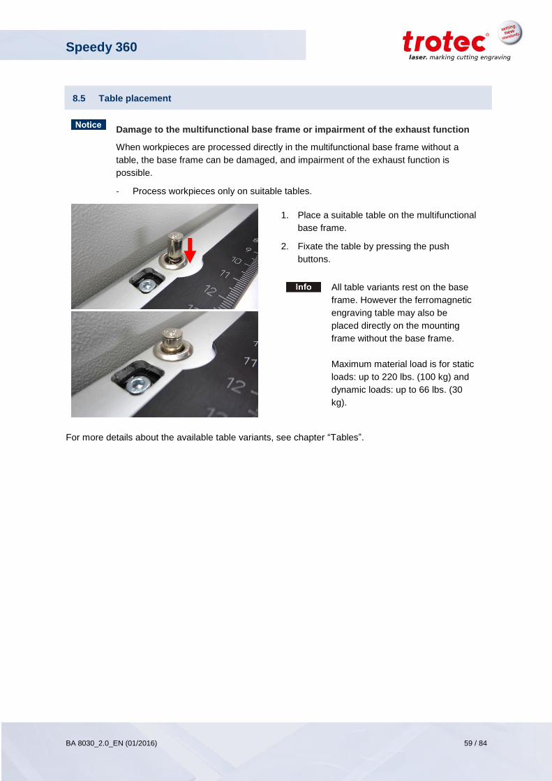
Speedy 360
BA 8030_2.0_EN (01/2016) 59 / 84
www.troteclaser.com
8.5 Table placement
Damage to the multifunctional base frame or impairment of the exhaust function
When workpieces are processed directly in the multifunctional base frame without a
table, the base frame can be damaged, and impairment of the exhaust function is
possible.
- Process workpieces only on suitable tables.
1. Place a suitable table on the multifunctional
base frame.
2. Fixate the table by pressing the push
buttons.
All table variants rest on the base
frame. However the ferromagnetic
engraving table may also be
placed directly on the mounting
frame without the base frame.
Maximum material load is for static
loads: up to 220 lbs. (100 kg) and
dynamic loads: up to 66 lbs. (30
kg).
For more details about the available table variants, see chapter “Tables”.
Speedy 360
BA 8030_2.0_EN (01/2016) 60 / 84
www.troteclaser.com
8.6 Focusing methods
Precise laser engraving depends on several factors. Apart from the right choice of lens, working tables
and a corresponding exhaust system, correct focusing plays a key role.
The correct setting of the focus, which means the right distance between the laser head and the
material to be engraved, is crucial for a perfect application result.
Manual focus mode
- Focus tool
Automatic focus modes
- Software focus (JobControl®)
- Light bar focus
- Sonar Technology™ (automatic focusing with ultrasonic sensor)
If workpieces with more than 30 kg have been placed on the table, the table must not be
moved up or down anymore as this might damage the mechanics of the machine.
It is mandatory to focus on the height of the material before loading material of 30 kg and
above.
Defects from head crashes (working head hits material or working table) are excluded
from warranty.
The machine described in this manuals is equipped either with light bar focus or Sonar
Technology™.
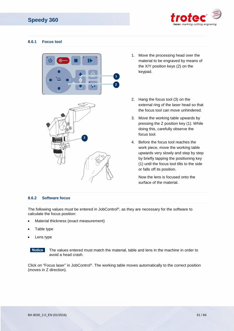
Speedy 360
BA 8030_2.0_EN (01/2016) 61 / 84
www.troteclaser.com
8.6.1 Focus tool
1. Move the processing head over the
material to be engraved by means of
the X/Y position keys (2) on the
keypad.
2. Hang the focus tool (3) on the
external ring of the laser head so that
the focus tool can move unhindered.
3. Move the working table upwards by
pressing the Z position key (1). While
doing this, carefully observe the
focus tool.
4. Before the focus tool reaches the
work piece, move the working table
upwards very slowly and step by step
by briefly tapping the positioning key
(1) until the focus tool tilts to the side
or falls off its position.
Now the lens is focused onto the
surface of the material.
8.6.2 Software focus
The following values must be entered in JobControl®, as they are necessary for the software to calculate the focus position:
Material thickness (exact measurement)
Table type
Lens type
The values entered must match the material, table and lens in the machine in order to avoid a head crash.
Click on “Focus laser” in JobControl®. The working table moves automatically to the correct position (moves in Z direction).
1
2
3
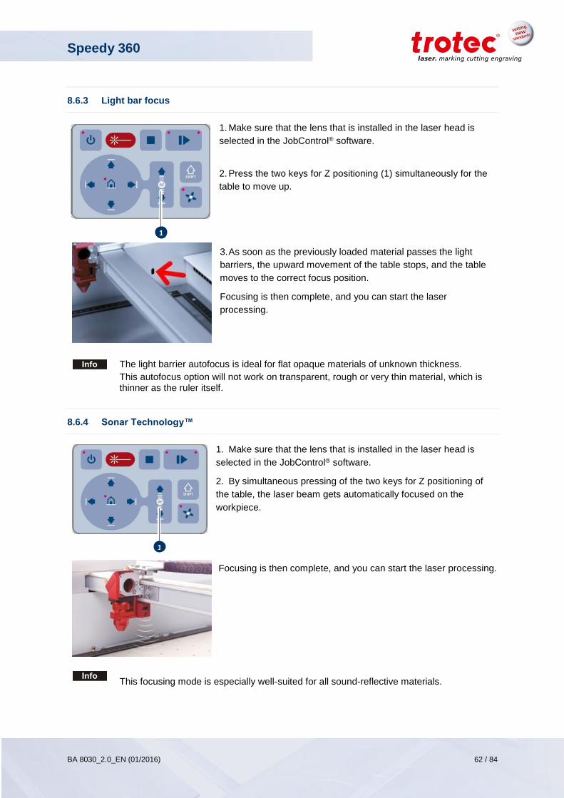
Speedy 360
BA 8030_2.0_EN (01/2016) 62 / 84
www.troteclaser.com
8.6.3 Light bar focus
1. Make sure that the lens that is installed in the laser head is
selected in the JobControl® software.
2. Press the two keys for Z positioning (1) simultaneously for the
table to move up.
3. As soon as the previously loaded material passes the light
barriers, the upward movement of the table stops, and the table
moves to the correct focus position.
Focusing is then complete, and you can start the laser
processing.
The light barrier autofocus is ideal for flat opaque materials of unknown thickness.
This autofocus option will not work on transparent, rough or very thin material, which is thinner as the ruler itself.
8.6.4 Sonar Technology™
1. Make sure that the lens that is installed in the laser head is
selected in the JobControl® software.
2. By simultaneous pressing of the two keys for Z positioning of
the table, the laser beam gets automatically focused on the
workpiece.
Focusing is then complete, and you can start the laser processing.
This focusing mode is especially well-suited for all sound-reflective materials.
1
1
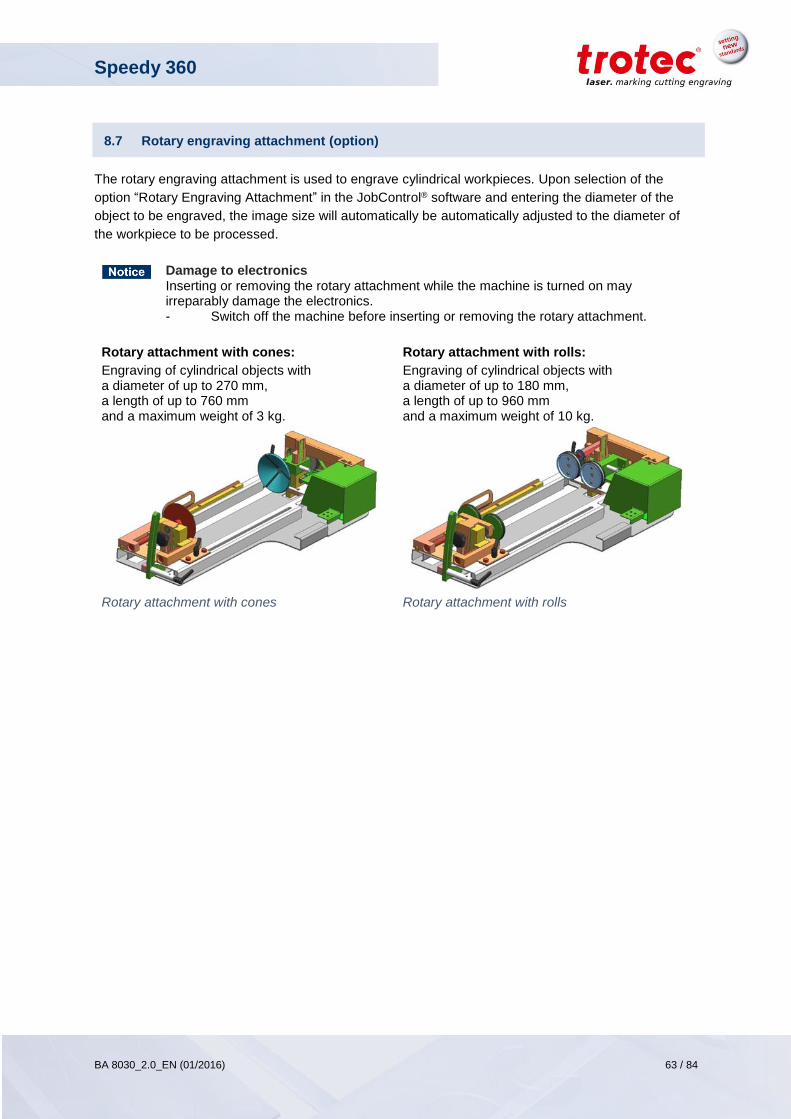
Speedy 360
BA 8030_2.0_EN (01/2016) 63 / 84
www.troteclaser.com
8.7 Rotary engraving attachment (option)
The rotary engraving attachment is used to engrave cylindrical workpieces. Upon selection of the
option “Rotary Engraving Attachment” in the JobControl® software and entering the diameter of the
object to be engraved, the image size will automatically be automatically adjusted to the diameter of
the workpiece to be processed.
Damage to electronics Inserting or removing the rotary attachment while the machine is turned on may irreparably damage the electronics. - Switch off the machine before inserting or removing the rotary attachment.
Rotary attachment with cones:
Engraving of cylindrical objects with a diameter of up to 270 mm, a length of up to 760 mm and a maximum weight of 3 kg.
Rotary attachment with rolls:
Engraving of cylindrical objects with a diameter of up to 180 mm, a length of up to 960 mm and a maximum weight of 10 kg.
Rotary attachment with cones
Rotary attachment with rolls
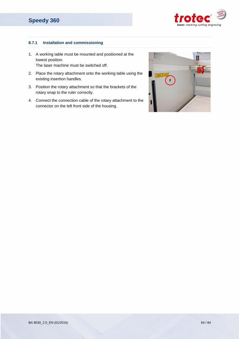
Speedy 360
BA 8030_2.0_EN (01/2016) 64 / 84
www.troteclaser.com
8.7.1 Installation and commissioning
1. A working table must be mounted and positioned at the
lowest position.
The laser machine must be switched off.
2. Place the rotary attachment onto the working table using the
existing insertion handles.
3. Position the rotary attachment so that the brackets of the
rotary snap to the ruler correctly.
4. Connect the connection cable of the rotary attachment to the
connector on the left front side of the housing.
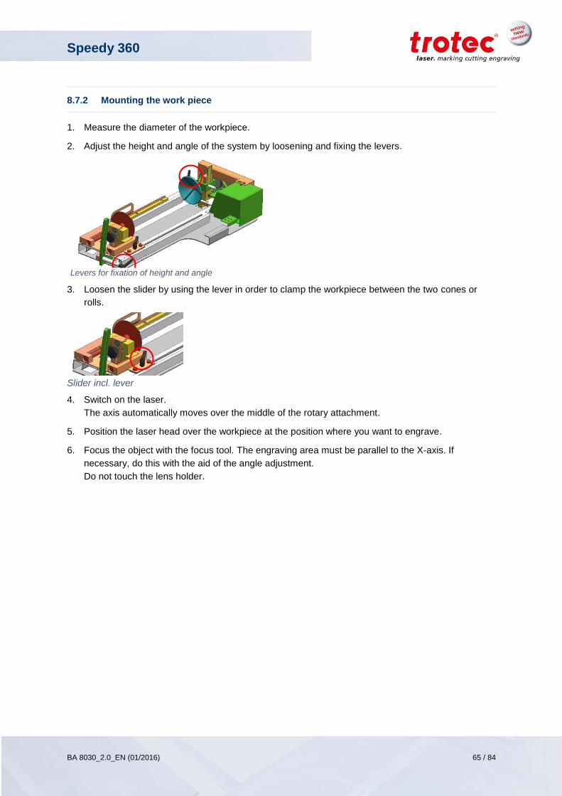
Speedy 360
BA 8030_2.0_EN (01/2016) 65 / 84
www.troteclaser.com
Levers for fixation of height and angle
8.7.2 Mounting the work piece
1. Measure the diameter of the workpiece.
2. Adjust the height and angle of the system by loosening and fixing the levers.
3. Loosen the slider by using the lever in order to clamp the workpiece between the two cones or
rolls.
Slider incl. lever
4. Switch on the laser.
The axis automatically moves over the middle of the rotary attachment.
5. Position the laser head over the workpiece at the position where you want to engrave.
6. Focus the object with the focus tool. The engraving area must be parallel to the X-axis. If
necessary, do this with the aid of the angle adjustment.
Do not touch the lens holder.
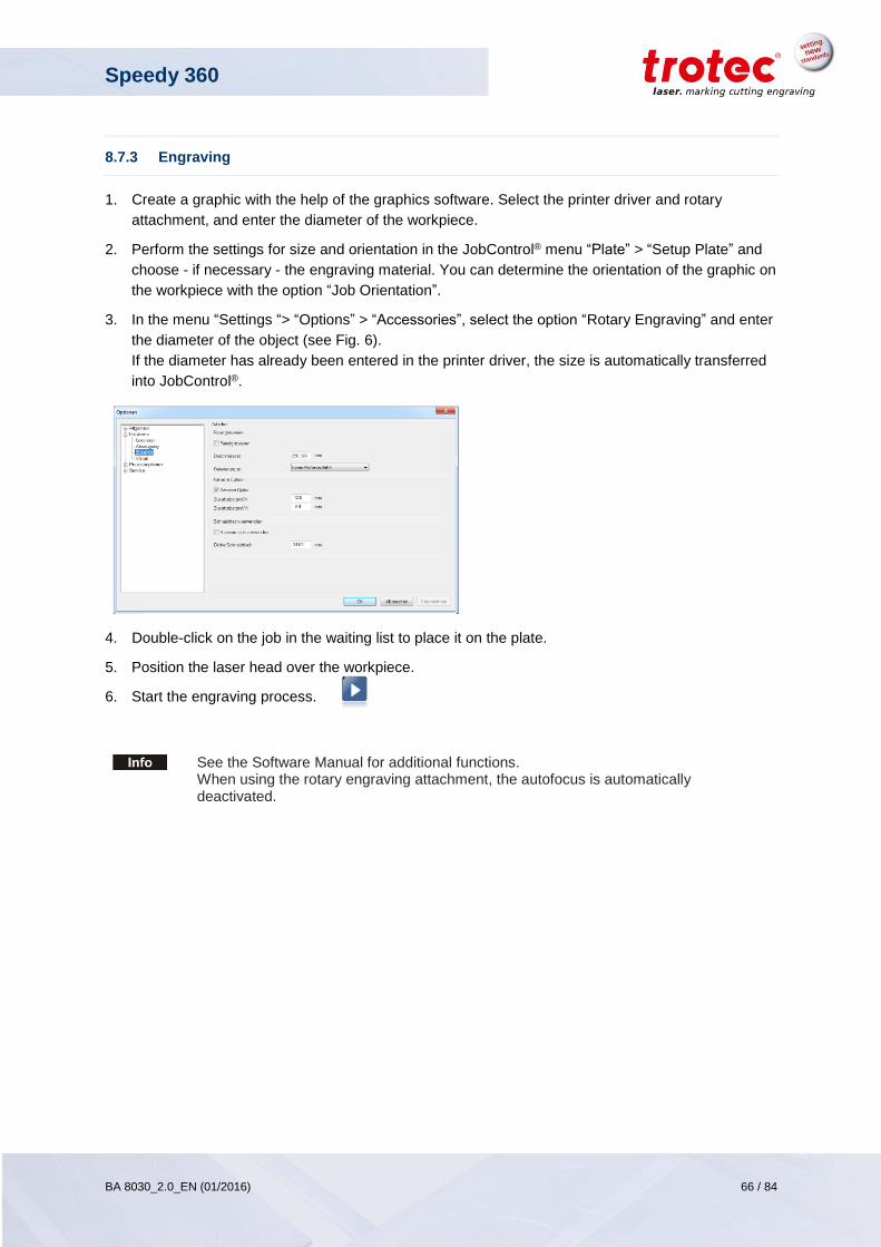
Speedy 360
BA 8030_2.0_EN (01/2016) 66 / 84
www.troteclaser.com
8.7.3 Engraving
1. Create a graphic with the help of the graphics software. Select the printer driver and rotary
attachment, and enter the diameter of the workpiece.
2. Perform the settings for size and orientation in the JobControl® menu “Plate” > “Setup Plate” and
choose - if necessary - the engraving material. You can determine the orientation of the graphic on
the workpiece with the option “Job Orientation”.
3. In the menu “Settings “> “Options” > “Accessories”, select the option “Rotary Engraving” and enter
the diameter of the object (see Fig. 6).
If the diameter has already been entered in the printer driver, the size is automatically transferred
into JobControl®.
4. Double-click on the job in the waiting list to place it on the plate.
5. Position the laser head over the workpiece.
6. Start the engraving process.
See the Software Manual for additional functions. When using the rotary engraving attachment, the autofocus is automatically deactivated.
Speedy 360
BA 8030_2.0_EN (01/2016) 67 / 84
www.troteclaser.com
8.8 Tips and tricks
8.8.1 Tips and tricks for laser engraving
The engraving depth can be varied by varying laser power or engraving speed. To increase the
engraving depth, reduce the speed or increase the power setting; thereby you increase the energy
input per area unit. Too deep engraving, however, reduces the quality of the details. For coated
materials, the required power depends on the kind and thickness of the coating. If the power setting is
too high, the individual lines become too thick, and a sharp picture cannot be achieved. The resolution
of the graphics should usually be 500 dpi. The dpi setting (number of laser dots per inch) depends on
the material. The lower this setting is, the lower the resolution of the engraved picture will be. This,
however, reduces flaming and increases the energy of a pulse, which can improve the overall result,
e.g. when engraving some sorts of plastic materials.
Protection foil:
Generally, remove the protection foil from the engraving area. However, leave the protection foil on
the area that is not to be engraved, to avoid scratching of the material. Protection foil can be useful to
protect adjacent material from debris during cutting.
Plastics:
The majority of available plastics can be easily engraved and cut with the laser. As most plastic
materials have a low melting point, a low PPI setting should be selected to reduce the danger of
melting.
Acrylic:
There are two different types of acrylic – cast and extruded. The cast acrylic becomes white or mat
after engraving, the extruded acrylic remains clear. Use extruded acrylic for engravings that are filled
with paint and cast acrylic for normal engravings. Cast acrylic can be best engraved without protection
foil. It is better to engrave the entire surface with a low energy setting.
Photo Engraving:
Scan the desired picture with a resolution of 300 dpi. Adjust brightness and contrast so that lighter
colors become lighter and darker colors become darker. The photo may look better if you use a filter to
sharpen the contours. Select a raster from the software. Use a raster with 20 to 100 lines per inch.
Increasing the number of lines per inch decreases the size of the points. With increasing number of
lines per inch, the size of the points decreases. If you cannot select a raster in your software, the
printer driver will select the raster automatically.
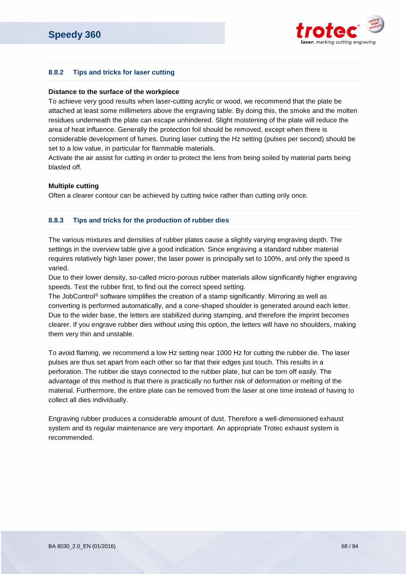
Speedy 360
BA 8030_2.0_EN (01/2016) 68 / 84
www.troteclaser.com
8.8.2 Tips and tricks for laser cutting
Distance to the surface of the workpiece
To achieve very good results when laser-cutting acrylic or wood, we recommend that the plate be
attached at least some millimeters above the engraving table. By doing this, the smoke and the molten
residues underneath the plate can escape unhindered. Slight moistening of the plate will reduce the
area of heat influence. Generally the protection foil should be removed, except when there is
considerable development of fumes. During laser cutting the Hz setting (pulses per second) should be
set to a low value, in particular for flammable materials.
Activate the air assist for cutting in order to protect the lens from being soiled by material parts being
blasted off.
Multiple cutting
Often a clearer contour can be achieved by cutting twice rather than cutting only once.
8.8.3 Tips and tricks for the production of rubber dies
The various mixtures and densities of rubber plates cause a slightly varying engraving depth. The
settings in the overview table give a good indication. Since engraving a standard rubber material
requires relatively high laser power, the laser power is principally set to 100%, and only the speed is
varied.
Due to their lower density, so-called micro-porous rubber materials allow significantly higher engraving
speeds. Test the rubber first, to find out the correct speed setting.
The JobControl® software simplifies the creation of a stamp significantly. Mirroring as well as
converting is performed automatically, and a cone-shaped shoulder is generated around each letter.
Due to the wider base, the letters are stabilized during stamping, and therefore the imprint becomes
clearer. If you engrave rubber dies without using this option, the letters will have no shoulders, making
them very thin and unstable.
To avoid flaming, we recommend a low Hz setting near 1000 Hz for cutting the rubber die. The laser
pulses are thus set apart from each other so far that their edges just touch. This results in a
perforation. The rubber die stays connected to the rubber plate, but can be torn off easily. The
advantage of this method is that there is practically no further risk of deformation or melting of the
material. Furthermore, the entire plate can be removed from the laser at one time instead of having to
collect all dies individually.
Engraving rubber produces a considerable amount of dust. Therefore a well-dimensioned exhaust
system and its regular maintenance are very important. An appropriate Trotec exhaust system is
recommended.
Speedy 360
BA 8030_2.0_EN (01/2016) 69 / 84
www.troteclaser.com
9 Maintenance
9.1 Safety notes
DANGER
Improper maintenance can cause serious injury or damage.
Maintenance may be carried out only by authorized, trained personnel who are familiar
with how to operate the machine and in strict observance of all safety instructions.
DANGER
Risk of fire or explosion
Improper handling of the machine may cause fire or explosion.
For cleaning the machine, do not use explosive or flammable substances or cleaning
agents.
No flammable or explosive liquids may be stored in or near the machine.
Always keep the system clean, and remove flammable parts from the working area or
exhaust area.
DANGER
Danger of electrical shock
Work on electrical fittings may be carried out only by qualified personnel and in strict
observance of the safety instructions.
Before any maintenance work takes place, disconnect the machine from the mains voltage
and make sure the system is de-energized.
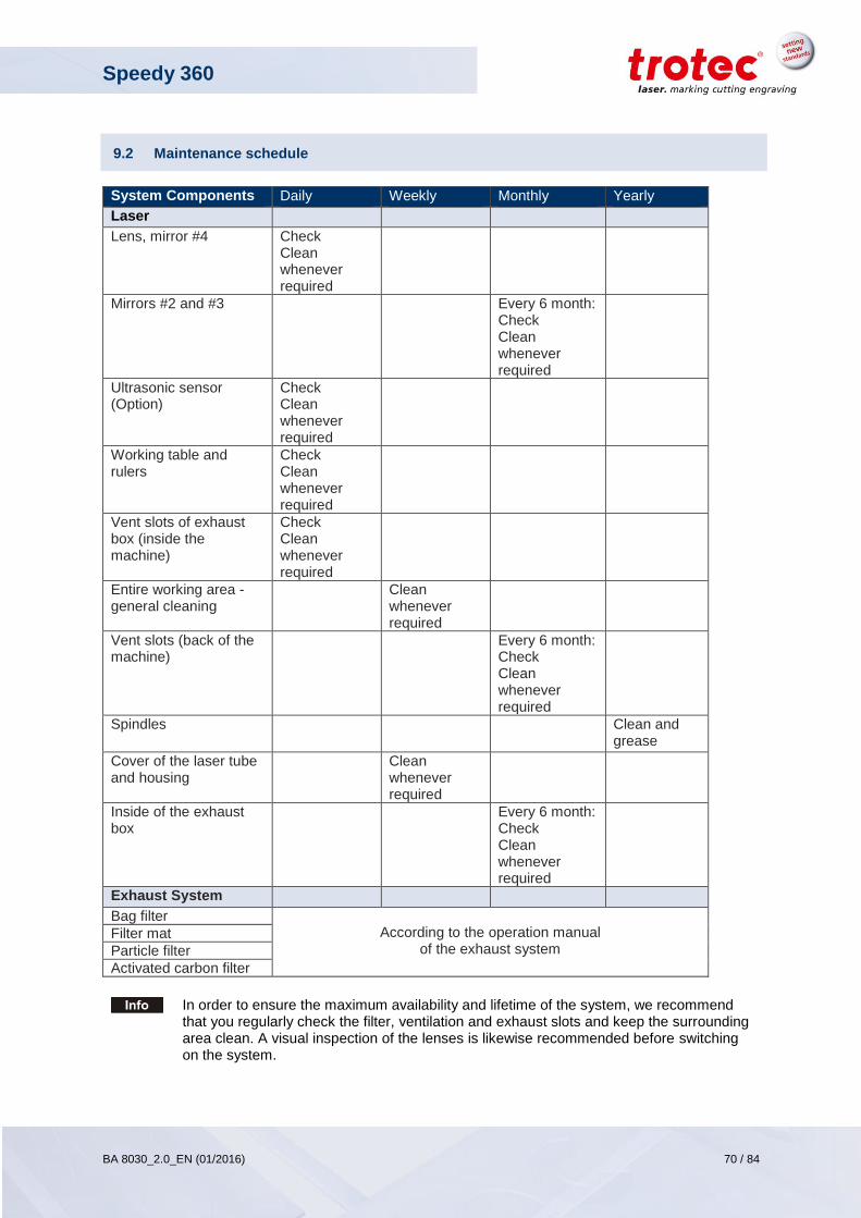
Speedy 360
BA 8030_2.0_EN (01/2016) 70 / 84
www.troteclaser.com
9.2 Maintenance schedule
System Components Daily Weekly Monthly Yearly
Laser
Lens, mirror #4 Check Clean whenever required
Mirrors #2 and #3 Every 6 month: Check Clean whenever required
Ultrasonic sensor (Option)
Check Clean whenever required
Working table and rulers
Check Clean whenever required
Vent slots of exhaust box (inside the machine)
Check Clean whenever required
Entire working area - general cleaning
Clean whenever required
Vent slots (back of the machine)
Every 6 month: Check Clean whenever required
Spindles Clean and grease
Cover of the laser tube and housing
Clean whenever required
Inside of the exhaust box
Every 6 month: Check Clean whenever required
Exhaust System
Bag filter According to the operation manual
of the exhaust system Filter mat
Particle filter
Activated carbon filter
In order to ensure the maximum availability and lifetime of the system, we recommend that you regularly check the filter, ventilation and exhaust slots and keep the surrounding area clean. A visual inspection of the lenses is likewise recommended before switching on the system.
Speedy 360
BA 8030_2.0_EN (01/2016) 71 / 84
www.troteclaser.com
9.3 Cleaning the machine
1. Move the engraving table into a position in which it is easiest for you to clean the surface with a
window cleaning agent and paper towels.
2. Switch off and disconnect the machine from the mains.
3. Open the transparent acrylic top lid and front panel.
4. Thoroughly remove all loose dirt particles and deposits in the interior of the machine (e.g. with a
vacuum cleaner or broom).
5. Clean the air guide plate and vent slots of the exhaust box inside the machine using a dry or damp
cloth or brush.
6. Clean the cover of the laser tube and vent slots at the back of the machine using a dry or damp
cloth.
7. Clean the transparent acrylic top lid using a dry or slightly damp cotton cloth. Do not use paper
towels as they could scratch the acrylic.
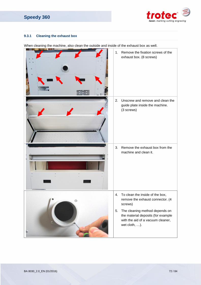
Speedy 360
BA 8030_2.0_EN (01/2016) 72 / 84
www.troteclaser.com
9.3.1 Cleaning the exhaust box
When cleaning the machine, also clean the outside and inside of the exhaust box as well.
1. Remove the fixation screws of the
exhaust box. (8 screws)
2. Unscrew and remove and clean the
guide plate inside the machine.
(3 screws)
3. Remove the exhaust box from the
machine and clean it.
4. To clean the inside of the box,
remove the exhaust connector. (4
screws)
5. The cleaning method depends on
the material deposits (for example
with the aid of a vacuum cleaner,
wet cloth, …).
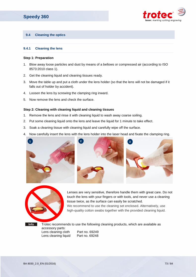
Speedy 360
BA 8030_2.0_EN (01/2016) 73 / 84
www.troteclaser.com
9.4 Cleaning the optics
9.4.1 Cleaning the lens
Step 1: Preparation
1. Blow away loose particles and dust by means of a bellows or compressed air (according to ISO
8573:2010 class 1).
2. Get the cleaning liquid and cleaning tissues ready.
3. Move the table up and put a cloth under the lens holder (so that the lens will not be damaged if it
falls out of holder by accident).
4. Loosen the lens by screwing the clamping ring inward.
5. Now remove the lens and check the surface.
Step 2: Cleaning with cleaning liquid and cleaning tissues
1. Remove the lens and rinse it with cleaning liquid to wash away coarse soiling.
2. Put some cleaning liquid onto the lens and leave the liquid for 1 minute to take effect.
3. Soak a cleaning tissue with cleaning liquid and carefully wipe off the surface.
4. Now carefully insert the lens with the lens holder into the laser head and fixate the clamping ring.
Lenses are very sensitive, therefore handle them with great care. Do not
touch the lens with your fingers or with tools, and never use a cleaning
tissue twice, as the surface can easily be scratched.
We recommend to use the cleaning set enclosed. Alternatively, use
high-quality cotton swabs together with the provided cleaning liquid.
Trotec recommends to use the following cleaning products, which are available as accessory parts: Lens cleaning cloth Part no. 69249 Lens cleaning liquid Part no. 69248
1
4
2
4 3
4
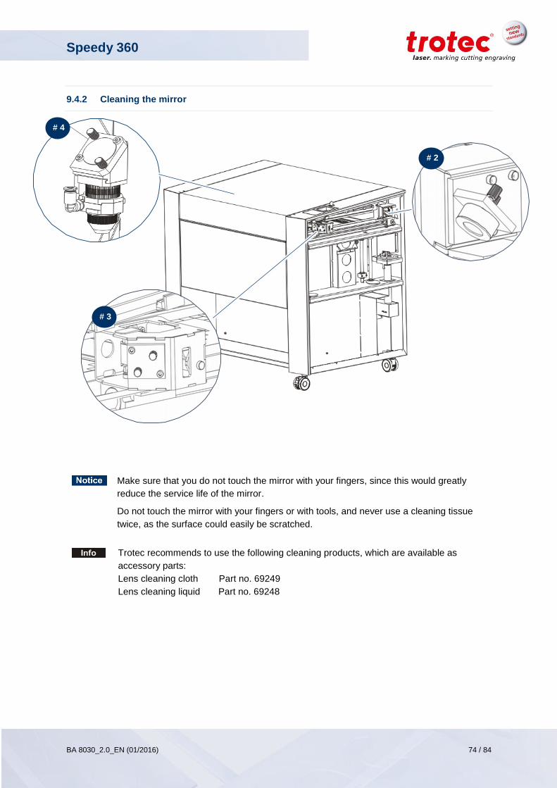
Speedy 360
BA 8030_2.0_EN (01/2016) 74 / 84
www.troteclaser.com
9.4.2 Cleaning the mirror
Make sure that you do not touch the mirror with your fingers, since this would greatly
reduce the service life of the mirror.
Do not touch the mirror with your fingers or with tools, and never use a cleaning tissue
twice, as the surface could easily be scratched.
Trotec recommends to use the following cleaning products, which are available as
accessory parts:
Lens cleaning cloth Part no. 69249
Lens cleaning liquid Part no. 69248
# 4
# 2
# 3
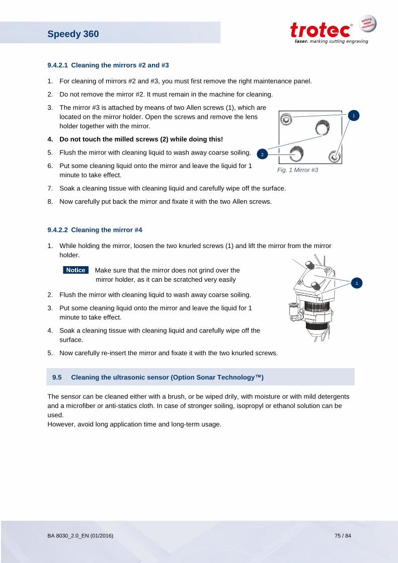
Speedy 360
BA 8030_2.0_EN (01/2016) 75 / 84
www.troteclaser.com
9.4.2.1 Cleaning the mirrors #2 and #3
1. For cleaning of mirrors #2 and #3, you must first remove the right maintenance panel.
2. Do not remove the mirror #2. It must remain in the machine for cleaning.
3. The mirror #3 is attached by means of two Allen screws (1), which are
located on the mirror holder. Open the screws and remove the lens
holder together with the mirror.
4. Do not touch the milled screws (2) while doing this!
5. Flush the mirror with cleaning liquid to wash away coarse soiling.
6. Put some cleaning liquid onto the mirror and leave the liquid for 1
minute to take effect.
7. Soak a cleaning tissue with cleaning liquid and carefully wipe off the surface.
8. Now carefully put back the mirror and fixate it with the two Allen screws.
9.4.2.2 Cleaning the mirror #4
1. While holding the mirror, loosen the two knurled screws (1) and lift the mirror from the mirror
holder.
Make sure that the mirror does not grind over the
mirror holder, as it can be scratched very easily
2. Flush the mirror with cleaning liquid to wash away coarse soiling.
3. Put some cleaning liquid onto the mirror and leave the liquid for 1
minute to take effect.
4. Soak a cleaning tissue with cleaning liquid and carefully wipe off the
surface.
5. Now carefully re-insert the mirror and fixate it with the two knurled screws.
9.5 Cleaning the ultrasonic sensor (Option Sonar Technology™)
The sensor can be cleaned either with a brush, or be wiped drily, with moisture or with mild detergents
and a microfiber or anti-statics cloth. In case of stronger soiling, isopropyl or ethanol solution can be
used.
However, avoid long application time and long-term usage.
1
Fig. 1 Mirror #3
2
1
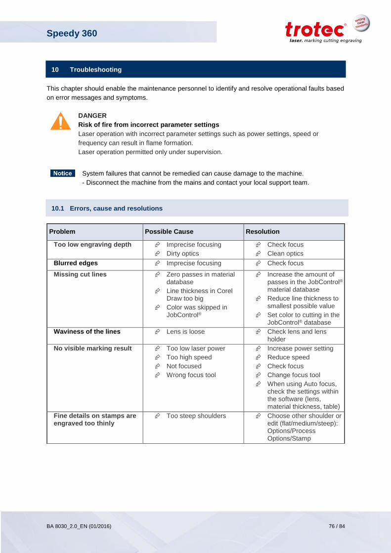
Speedy 360
BA 8030_2.0_EN (01/2016) 76 / 84
www.troteclaser.com
10 Troubleshooting
This chapter should enable the maintenance personnel to identify and resolve operational faults based
on error messages and symptoms.
DANGER
Risk of fire from incorrect parameter settings
Laser operation with incorrect parameter settings such as power settings, speed or
frequency can result in flame formation.
Laser operation permitted only under supervision.
System failures that cannot be remedied can cause damage to the machine.
- Disconnect the machine from the mains and contact your local support team.
10.1 Errors, cause and resolutions
Problem Possible Cause Resolution
Too low engraving depth Imprecise focusing
Dirty optics
Check focus
Clean optics
Blurred edges Imprecise focusing Check focus
Missing cut lines Zero passes in material database
Line thickness in Corel Draw too big
Color was skipped in JobControl®
Increase the amount of passes in the JobControl® material database
Reduce line thickness to smallest possible value
Set color to cutting in the JobControl® database
Waviness of the lines Lens is loose Check lens and lens holder
No visible marking result Too low laser power
Too high speed
Not focused
Wrong focus tool
Increase power setting
Reduce speed
Check focus
Change focus tool
When using Auto focus, check the settings within the software (lens, material thickness, table)
Fine details on stamps are engraved too thinly
Too steep shoulders Choose other shoulder or edit (flat/medium/steep): Options/Process Options/Stamp
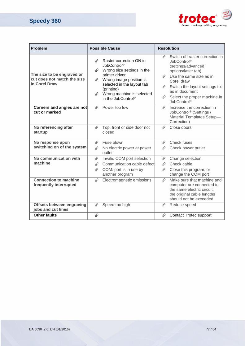
Speedy 360
BA 8030_2.0_EN (01/2016) 77 / 84
www.troteclaser.com
Problem Possible Cause Resolution
The size to be engraved or cut does not match the size in Corel Draw
Raster correction ON in JobControl®
Wrong size settings in the printer driver
Wrong image position is selected in the layout tab (printing)
Wrong machine is selected in the JobControl®
Switch off raster correction in JobControl® (settings/advanced options/laser tab)
Use the same size as in Corel draw
Switch the layout settings to: as in document
Select the proper machine in JobControl®
Corners and angles are not cut or marked
Power too low Increase the correction in JobControl® (Settings / Material Templates Setup—Correction)
No referencing after startup
Top, front or side door not closed
Close doors
No response upon switching on of the system
Fuse blown
No electric power at power outlet
Check fuses
Check power outlet
No communication with machine
Invalid COM port selection
Communication cable defect
COM: port is in use by another program
Change selection
Check cable
Close this program, or change the COM port
Connection to machine frequently interrupted
Electromagnetic emissions Make sure that machine and computer are connected to the same electric circuit; the original cable lengths should not be exceeded
Offsets between engraving jobs and cut lines
Speed too high Reduce speed
Other faults Contact Trotec support
Speedy 360
BA 8030_2.0_EN (01/2016) 78 / 84
www.troteclaser.com
11 Contact details
11.1 Technical Support
In case of questions, contact our experienced local technical support team.
For global service contact numbers and further information please see our website, section “Support”:
www.troteclaser.com
When calling, please make sure that the machine is in your immediate vicinity, and that you have the following information ready (see response form):
What happened and what you were doing when the problem arose.
What you have done so far to correct the problem.
Serial no (see type plate)
Error code
11.2 Local Offices / Sales
Our store locator and detailed information on our offices in your area can be found on our website in section “Contact”, “Local Office”:
www.troteclaser.com
11.3 Technical Documentation
For feedback or to suggest changes to this manual, contact:
Technical documentation: +43 (0) 7242 239 - 7000
E-mail: [email protected]
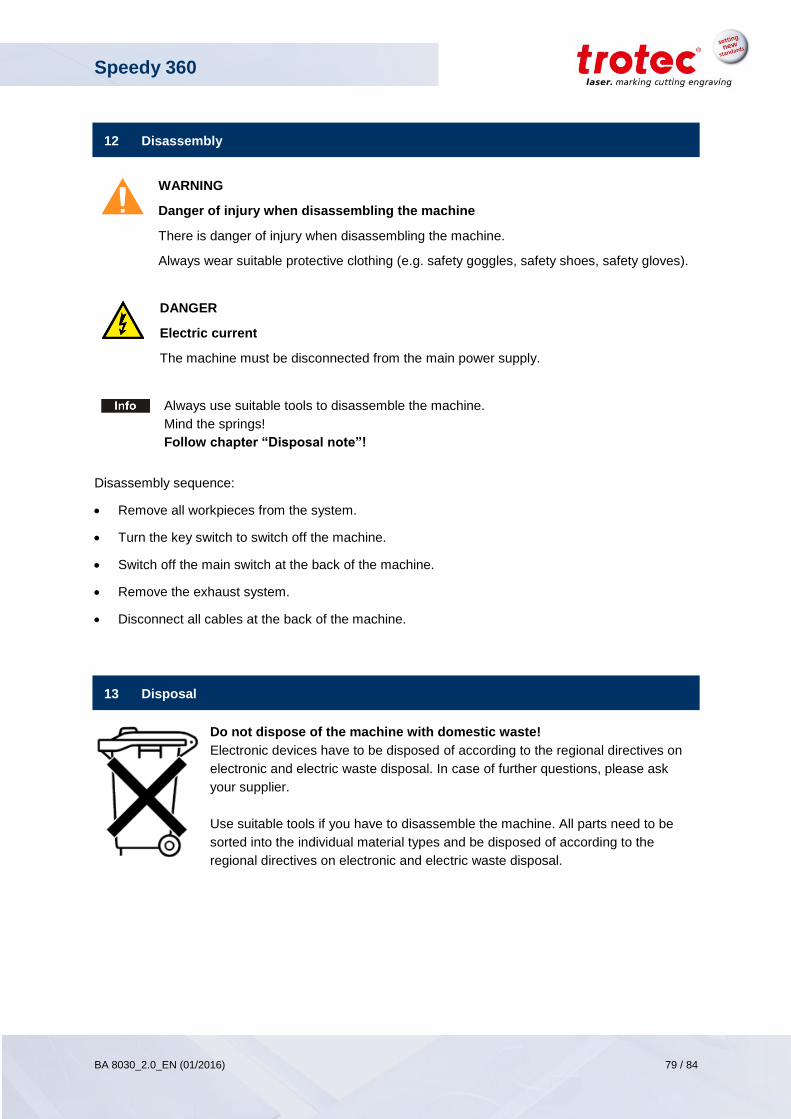
Speedy 360
BA 8030_2.0_EN (01/2016) 79 / 84
www.troteclaser.com
12 Disassembly
WARNING
Danger of injury when disassembling the machine
There is danger of injury when disassembling the machine.
Always wear suitable protective clothing (e.g. safety goggles, safety shoes, safety gloves).
DANGER
Electric current
The machine must be disconnected from the main power supply.
Always use suitable tools to disassemble the machine.
Mind the springs!
Follow chapter “Disposal note”!
Disassembly sequence:
Remove all workpieces from the system.
Turn the key switch to switch off the machine.
Switch off the main switch at the back of the machine.
Remove the exhaust system.
Disconnect all cables at the back of the machine.
13 Disposal
Do not dispose of the machine with domestic waste!
Electronic devices have to be disposed of according to the regional directives on
electronic and electric waste disposal. In case of further questions, please ask
your supplier.
Use suitable tools if you have to disassemble the machine. All parts need to be
sorted into the individual material types and be disposed of according to the
regional directives on electronic and electric waste disposal.
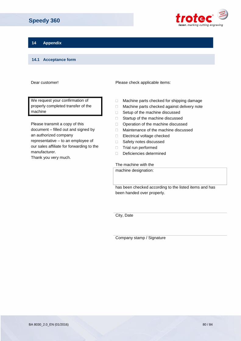
Speedy 360
BA 8030_2.0_EN (01/2016) 80 / 84
www.troteclaser.com
14 Appendix
14.1 Acceptance form
Dear customer! Please check applicable items:
We request your confirmation of
properly completed transfer of the
machine
Machine parts checked for shipping damage
Machine parts checked against delivery note
Setup of the machine discussed
Startup of the machine discussed
Operation of the machine discussed
Maintenance of the machine discussed
Electrical voltage checked
Safety notes discussed
Trial run performed
Deficiencies determined
The machine with the
Please transmit a copy of this
document – filled out and signed by
an authorized company
representative – to an employee of
our sales affiliate for forwarding to the
manufacturer.
Thank you very much.
machine designation:
has been checked according to the listed items and has
been handed over properly.
City, Date
Company stamp / Signature
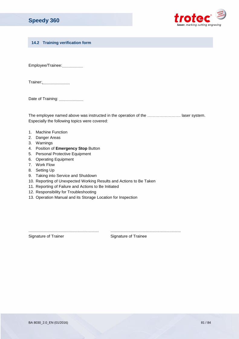
Speedy 360
BA 8030_2.0_EN (01/2016) 81 / 84
www.troteclaser.com
14.2 Training verification form
Employee/Trainee:
Trainer:
Date of Training:
The employee named above was instructed in the operation of the ……………………. laser system.
Especially the following topics were covered:
1. Machine Function
2. Danger Areas
3. Warnings
4. Position of Emergency Stop Button
5. Personal Protective Equipment
6. Operating Equipment
7. Work Flow
8. Setting Up
9. Taking into Service and Shutdown
10. Reporting of Unexpected Working Results and Actions to Be Taken
11. Reporting of Failure and Actions to Be Initiated
12. Responsibility for Troubleshooting
13. Operation Manual and its Storage Location for Inspection
............................................................... ...............................................................
Signature of Trainer Signature of Trainee

Speedy 360
BA 8030_2.0_EN (01/2016) 82 / 84
www.troteclaser.com
14.3 Response form
In case of any trouble with the machine, please provide the following information and additionally
create a service file (the procedure for creation of a service file is described on the following pages).
Date
Machine Details Contact Details
Serial Number First Name
JobControl®
Version Last Name
Driver Version Country
Layout Software Phone
Firmware Version Email
Problem Description
Does an error message show up on the PC; if so, which?
What happened before the error occurred? (Thunder & Lightning, Windows-Update, …)
What attempts were made to solve the problem?
Please send the information to your sales representative, your local support or to
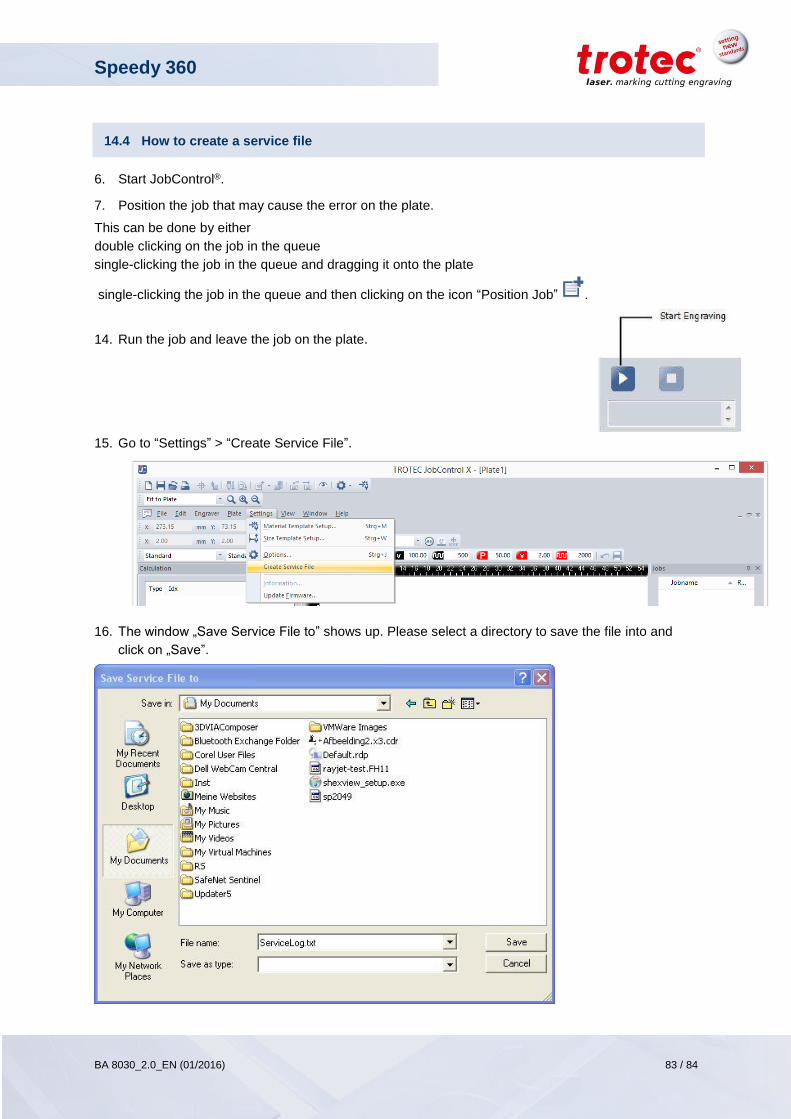
Speedy 360
BA 8030_2.0_EN (01/2016) 83 / 84
www.troteclaser.com
14.4 How to create a service file
6. Start JobControl®.
7. Position the job that may cause the error on the plate.
This can be done by either
double clicking on the job in the queue
single-clicking the job in the queue and dragging it onto the plate
single-clicking the job in the queue and then clicking on the icon “Position Job” .
14. Run the job and leave the job on the plate.
15. Go to “Settings” > “Create Service File”.
16. The window „Save Service File to” shows up. Please select a directory to save the file into and
click on „Save”.
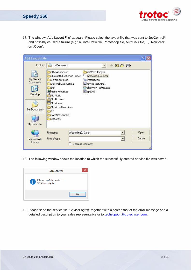
Speedy 360
BA 8030_2.0_EN (01/2016) 84 / 84
www.troteclaser.com
17. The window „Add Layout File” appears. Please select the layout file that was sent to JobControl®
and possibly caused a failure (e.g.: a CorelDraw file, Photoshop file, AutoCAD file,…). Now click
on „Open”.
18. The following window shows the location to which the successfully created service file was saved.
19. Please send the service file “SeviceLog.txt” together with a screenshot of the error message and a
detailed description to your sales representative or to [email protected].