Embed Size (px)
Citation preview
III
UNIV
ER
SID
AD
·C A R L OS I I I ·
DE
MA
D
RID:
UNIVERSITY CARLOS III OF MADRID
Department of Telematics Engineering
Master of Science Thesis
Speeding IPv6 Address Autoconfiguration for VANETs throughCaching
Author: Marco GramagliaDipl.Eng. in Telecommunications
Supervisors:Mar ıa Calderon Pastor, Ph.D.Carlos Jesus Bernardos Cano, Ph.D.
Leganes, September 2009
Abstract
GeoSAC is a mechanism that enables IPv6 address autoconfiguration in vehicular net-works based on geographic routing. It is built using one of the most know networking stackin the field of VANET, the one proposed by the car-to-car consortium. GeoSAC adaptsthe existing IPv6 stateless address autoconfiguration protocol to VANETs. In this thesiswe analytically model GeoSAC in order to evaluate its perfomance, especially in terms ofconfiguration times. Then we propose an optimization for this protocol using router adver-tisement caching which has also been modeled. We validate both the model we proposed bymeans of simulation. Simulation results show that our optimization significantly improvesthe performance in terms of configuration time but also for signalling overhead.
i
Table of Contents
1 Introduction 1
2 State of the Art 32.1 Car to Car system architecture . . . . . . . . . . . . . . . . . . . . . .. . 42.2 Related work . . . . . . . . . . . . . . . . . . . . . . . . . . . . . . . . . 5
3 GeoSAC 73.1 GeoSAC advantages . . . . . . . . . . . . . . . . . . . . . . . . . . . . . 83.2 GeoSAC functionalities . . . . . . . . . . . . . . . . . . . . . . . . . . .. 9
4 GeoSAC performance analysis 104.1 With perfect multi hop connectivity . . . . . . . . . . . . . . . . .. . . . 104.2 Without perfect multi hop connectivity . . . . . . . . . . . . . .. . . . . . 114.3 Configuration time . . . . . . . . . . . . . . . . . . . . . . . . . . . . . . 12
5 Enabling caching to improve GeoSAC performance 145.1 Analytical model . . . . . . . . . . . . . . . . . . . . . . . . . . . . . . . 14
6 Model validation and results 166.1 Performance evaluation . . . . . . . . . . . . . . . . . . . . . . . . . . .. 18
7 Conclusions and future work 22
References 23
ii
List of Figures
2.1 The car-to-car architecture . . . . . . . . . . . . . . . . . . . . . . .. . . 4
3.1 The GeoSac architecture . . . . . . . . . . . . . . . . . . . . . . . . . . .8
6.1 The simulator scheme . . . . . . . . . . . . . . . . . . . . . . . . . . . . . 166.2 Tconf , DRSU =1000mR=150m . . . . . . . . . . . . . . . . . . . . . . . 176.3 Probability of caching of a RA,DRSU =1500mR=300m . . . . . . . . . . 186.4 Probability of caching of an RA,DRSU =2000m (top)DRSU =1000m (bot-
tom) withR=300m . . . . . . . . . . . . . . . . . . . . . . . . . . . . . . 196.5 Probability of caching of a RA,DRSU =2000m (top)DRSU =1000m (bot-
tom) withR=150m . . . . . . . . . . . . . . . . . . . . . . . . . . . . . . 20
iii
Chapter 1
Introduction
Vehicular networks are a solution for providing connectivity among vehicles travellingalong roads. This connectivity can also be extended to an infrastructured network, suchas the Internet, by placing fixed installations on road borders. A couple of years ago theterm VANET (Vehicular ad hoc networks) was introduced, joining mobile ad hoc networks(MANETs) and Inter Vehicle Systems (IVC). Research effortsin this area are driven es-pecially by the goal of improving safety and traffic efficiency. Therefore governments, carmanufacturers and telecommunication players are working together towards the definitionof a new communication standard that enables drivers to takeadvantage from the improvedcapabilities of their vehicles.Hence, the most common considered applications are relatedto increasing traffic yields andsafety, especially collision warning systems and intelligent vehicle navigation. These ap-plications have the potential to make travel considerably more efficient, pleasant and safe.Although most efforts have been done to standardize these two categories of applications,a third one is increasing its importance inside VANETs sphere: infotainment. Infotainmentapplications will use an available global connectivity inside the vehicle to provide classicaland new Internet applications. This will increase the adoption of vehicular communicationsystems by the users, because they will see an added value from the installation of such de-vices inside their vehicles. Enabling IP connectivity in VANETs means also make vehiclesbecome an active part of the Internet, with the need to be compliant with all the protocolsand the mechanism used in the core network.An example of these functionalities is IP address autoconfiguration. As every vehicle will bean operative node in the network, a valid address assignation technique is needed in order toprovide a good interconnection between VANETs and the Internet. At the current state of theart, the solution for this problem has not been reached yet. The lack of standard protocols inthis field coming from mobile ad hoc networks is reflected and amplified in VANETs, wherethe possible high number of nodes and their quick mobility make applying existing solutionseven more difficult.GeoSAC, (Geographic scoped stateless address configuration) is a proposal by Baldessariet. al. [2] that tackles this problem, by bringing standardized IPv6 schemes into VANETs.It make use of geographical networking capabilities, whichare currently provided in mostof the VANET proposed architectures being standardized nowadays. In this particular case,GeoSAC was built on top of the stack provided by the Car-to-car communication consortium
1
2 Chapter 1. Introduction
(C2C-CC)1. In [2], GeoSAC performance was modelled assuming a high vehicular densityand evaluated by deploying a testbed of four vehicles and tworoad infrastructure nodes.In this thesis we provide an analytical model of GeoSAC and, based on analysis, we proposean improvement technique based on caching. Finally we proveour analytical evaluation bymeans of simulation and we show that our caching optimization significantly improves theperformance of GeoSAC.The rest of the thesis is structured as follows: in chapter 2 we present the state of the artregarding IP address autoconfiguration in VANETs, then in chapter 3 we focus on GeoSACsolution. In chapter 4 we present our analytical model of GeoSAC, then in chapter 5 wepropose our improvement based on caching. We validate the proposed models and showsimulation results in chapter 6, before concluding in chapter 7.
1www.car-to-car.org
Chapter 2
State of the Art
Despite IPv4 being the most deployed layer three protocol inthe Internet, all theworkgroups active in the VANET field (IEEE 16091, ISO TC 204CALM 2, the Car-to-CarCommunication ConsortiumC2C-CC and the ETSI TC ITS3) decided to include IPv6 asnetwork layer protocol in their stacks, due to its larger addressing space. Most of themdeveloped a multi hop IPv6 based infrastructure, so it is expected that IPv6 role is becomingmore and more relevant in this area.In this thesis, it is furthermore assumed to exists a short range wireless communicationtechnology. In particular, the IEEE has recently standardized a new amendment of the802.11 family (the IEEE 802.11p)4 which was designed to be used in the new ISM(industrial, scientific and medical) band that the Europeanspectrum authority assigned forvehicular networks (around 5.9GHz). It covers PHY and MAC layer of the OSI modeland uses seven different channel of 10MHz around the 5.9 GHz band. Six of them areservice channel (used for data transmission) and the last isused for control purposes. Thiscontrol channel is used in ad hoc mode and it is employed for the initial vehicle detectionand for the establishment of communications. The WAVE (Wireless Access in VehicularEnvironments) 1609 family of standard complements 802.11pdefining additional aspectssuch as security mechanisms, multi channel operations or network services.All the standardization working groups previously cited are developing a multi hop IPsublayer, either for safety or non safety purposes, extending the coverage using othervehicles as relays. This scenario offers many possible applications for this technology but,on the other hand, it poses the difficulty of deploying IPv6 interms of routing, security,privacy and mobility.IP address autoconfiguration in VANETs is still an open issue, especially because nosuitable solution has been found for MANETs yet5. The most important problem willbe pointed out after introducing the proposed solution by the car-to-car communicationconsortium for the VANET architecture, which will be the base for this thesis.
1www.standards.its.dot.gov/fact_sheet.asp?f=802www.tc204wg16.de3www.etsi.org4www.ieee802.org/11/Reports/tgp_update.htm5AUTOCONF WG is still working on the standardization of a solution
3
4 Chapter 2. State of the Art
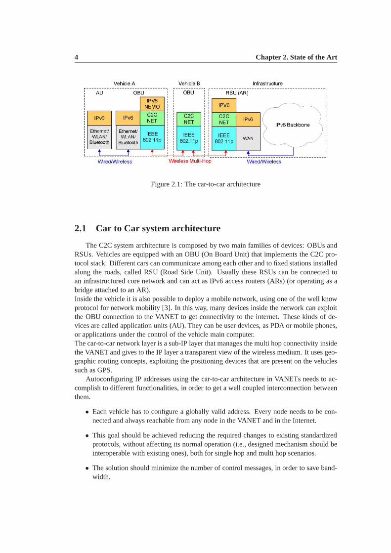
Figure 2.1: The car-to-car architecture
2.1 Car to Car system architecture
The C2C system architecture is composed by two main familiesof devices: OBUs andRSUs. Vehicles are equipped with an OBU (On Board Unit) that implements the C2C pro-tocol stack. Different cars can communicate among each other and to fixed stations installedalong the roads, called RSU (Road Side Unit). Usually these RSUs can be connected toan infrastructured core network and can act as IPv6 access routers (ARs) (or operating as abridge attached to an AR).Inside the vehicle it is also possible to deploy a mobile network, using one of the well knowprotocol for network mobility [3]. In this way, many devicesinside the network can exploitthe OBU connection to the VANET to get connectivity to the internet. These kinds of de-vices are called application units (AU). They can be user devices, as PDA or mobile phones,or applications under the control of the vehicle main computer.The car-to-car network layer is a sub-IP layer that manages the multi hop connectivity insidethe VANET and gives to the IP layer a transparent view of the wireless medium. It uses geo-graphic routing concepts, exploiting the positioning devices that are present on the vehiclessuch as GPS.
Autoconfiguring IP addresses using the car-to-car architecture in VANETs needs to ac-complish to different functionalities, in order to get a well coupled interconnection betweenthem.
• Each vehicle has to configure a globally valid address. Everynode needs to be con-nected and always reachable from any node in the VANET and in the Internet.
• This goal should be achieved reducing the required changes to existing standardizedprotocols, without affecting its normal operation (i.e., designed mechanism should beinteroperable with existing ones), both for single hop and multi hop scenarios.
• The solution should minimize the number of control messages, in order to save band-width.
5 Chapter 2. State of the Art
• The technique has to be functionally coupled with a network mobility protocol. Inother words, it has to be suitable for movement detection.
• If several RSUs are reachable by a node, a gateway selection procedure needs to beactivated.
• The mechanism must not rely on a single centralized entity onthe network (i.e. apotential point of failure), but rather be completely distributed.
• The solution has to provide security, integrity and privacy. Vehicles movement shouldnot be trackable from the network.
2.2 Related work
The most important issue in VANETs that makes standard IP autoconfiguration proto-cols unsuitable is the lack of a single multicast capable link for signalling. This problem ispresent also in MANETs due to the fact that there is not a clearnotion of link. Because oftheir multi hop nature, defining a not ambiguous concept of nodes belonging to the samelink it is not trivial. For the same reason, also duplicate address detection (DAD) schemesbecome more complicated than in wired networks. For solvingthis issue an IETF Work-ing Group called AUTOCONF was created in 2005. But even before its creation a lot ofproposals have been raised, especially for MANETs. Some of them make the assumptionof not being connected to the Internet but, as one of our goalsis to be fully compliant withstandard Internet protocols, we are focusing only on protocols that assume to be connectedto the Internet through one or more gateways.Ruffino et. al. [8] propose a solution based on a slightly modification of OLSR, a routingprotocol for ad-hoc networks. Each node needs to set up a temporary address (PADD) whichis MANET scoped and exchanges OLSR messages using it. In thissolution, gateways act asaccess routers, and spread their prefix (each gateway has a different IPv6 prefix) by meansof a new OLSR message type called Prefix Advertisement (PA). When a node gets PA mes-sages, it is able to build a set of valid IPv6 global addressesand finally chooses among themits Designated Secondary Address (DSADD). Every node broadcasts all its valid prefixesinto OLSR messages, so the network will be spread with all theprefixes available from thegateways. This solution needs a specific routing protocol tobe active in the network (OLSR)and each node has to create a MANET scoped address. Moreover the authors do not providea duplicated address detection mechanism.Templin et. al.[5] propose a solution based on DHCPv6. Theiridea is to set up a “virtual eth-ernet” adaptor placed on a “virtual link” that connects eachnode in the MANET. Using thisvirtual interface, nodes can configure globally valid addresses using the standard DHCPv6.The main advantage of this approach is that it reuses a well known and standardized pro-tocol like DHCPv6, enables prefix delegation and ensures unique address assignment. Onthe other hand, it needs to store state into the nodes, it is not fully distributed and does notprovide any mechanism for movement detection.Vehicular Address Configuration (VAC) is the proposal [4] made by Fazio et. al. This solu-tion was specifically tailored for vehicular environments,exploiting VANETs topology withan enhanced DHCP protocol. In this solution each node is supposed to be into the coverage

6 Chapter 2. State of the Art
range of a leader. Leaders are organized in a connected chain, in a hierarchical way. Onlyleaders communicate among each other keeping addressing information up to date. Thislimits the signalling also because each leader behave as a small DHCP server for non-leadernodes. The main drawback for this solution is the possible security problem, having all thecritical tasks maintained by the leaders.
Chapter 3
GeoSAC
GeoSAC [2] (Geographic scoped stateless address configuration) is a proposal made byBaldessari et. al. in 2008. It consists in adapting the existing IPv6 SLAAC mechanism(Stateless address autoconfiguration), tailoring it for the vehicular network scenario.In wired networks there is the concept of link and all the nodes belonging to a common Ac-cess Router can be easily identified and addressed. In VANETs, this concept is not clear, asnodes that maybe are not sharing the same layer 2 link, have tobe in the same layer 3 link.This is because of the multi hop behavior of VANET. GeoSAC defines the concept of layer3 link in a geographical way: all the nodes that are belongingto a well defined geographicalarea have to share the same layer 3 link and will receive the same copy of a multicast mes-sage. Every area has an access router that is in charge of it, by sending router advertisements.GeoSAC protocol was built upon the car-to-cat network stack. Using this stack, GeoSACcan exploit its subIP layer, which provides multi hop connectivity and emulate a link whichthe IP layer can use. Broadcast and multicast domains are managed by this sublayer andthe layer 3 scope is actually managed by geographical filtering of messages. It would bealso possible to define areas based on hop distance, but the extremely short life of the linksdiscourage this kind of approach. In this way, any gateway (that acts also as Access router)which is connected to the network can multicast IPv6 router advertisements that reach all thenodes placed within a well defined area. In car-to-car architecture, RSUs will act as ARs.When a node receives an RA, it applies a geographic checking and processes the message(i.e. forwards it up on the stack to the IPv6 layer) only if thenode is located inside the arealeaded by the sender Access Router. This phase could be called geocast procedure. If allthe nodes within an area have connectivity to the AR (that is,if there exists a multi hop pathbetween every node and the AR) after a certain amount of time all the nodes of the area willhave received a Router Advertisement.From that moment nodes follow standard IPv6 SLAAC mechanism: they generate a validglobal IPv6 address using the global prefix broadcast in the RA and their own MAC layeraddress. As it is supposed that each MAC address is different(and at least in different macroareas they do) from the others, and each Access Router broadcasts a different prefix, it isensured the uniqueness of the address, and a DAD procedure isnot needed anymore.The benefit of GeoSAC can be furthermore maximized by choosing areas and prefixes ac-cording to geographic criteria. Using adjacent and not overlapping areas, the followingadvantages can be achieved.
7
8 Chapter 3. GeoSAC
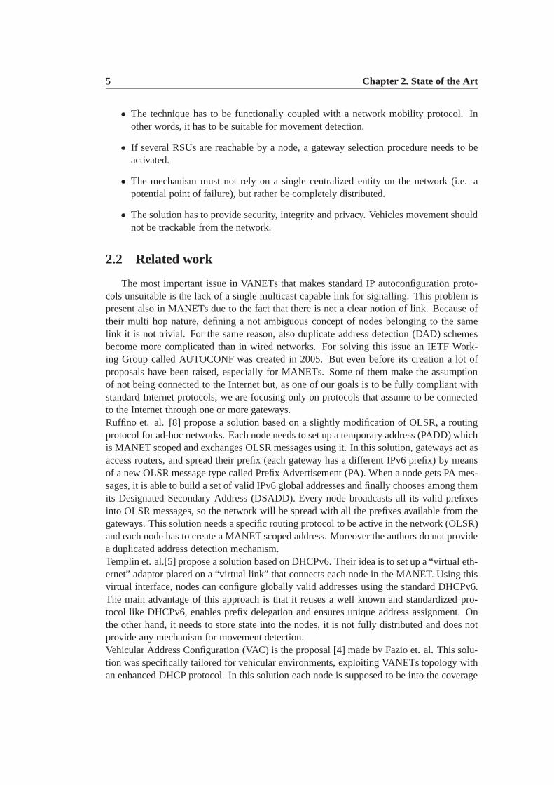
Figure 3.1: The GeoSac architecture
3.1 GeoSAC advantages
• The network infrastructure is in charge of the gateway selection, by assigning a dif-ferent gateway for every area, and each gateway is unique because there is only onegateway per each area.
• It is achieved a network partitioning that supports movement detection. This is veryuseful for IPv6 mobility protocol and it could be furthermore exploited by using alocation service. Another interesting property is that a vehicle moving through theareas will never be in grey areas, where it needs to choose among different prefixes orgateways.
• This VANET partitioning also enables a matching between geographical areas andIPv6 prefixes. This is effective when a location based application is deployed and canbe used coupled with some already proposed scheme for geographic IPv6 prefix for-mat, or extended DNS. Especially this second one can be useful in some applications.For example, imagine that you want to send a message warning for some accident toall the vehicles from the kilometre 2 to the kilometre 10 of a given road. This can beeasily achieved by resolving this geographical location ina set of prefixes, and thenbroadcasting the information into the selected areas.
9 Chapter 3. GeoSAC
3.2 GeoSAC functionalities
Besides these advantages, GeoSAC also accomplishes with the functionality explainedin chapter 2.
• GeoSAC configures a valid global IPv6 address in each node if the RA is broadcastwithin the area. This solution allows the standard SLAAC mechanism to be usedin VANETs, using multi hop links instead of multicast capable links assumed in thestandard version.
• This solution has a low complexity. Each node only needs to geographically filter amessage and then process it in the normal way.
• Using a geocast solution, RAs are spread inside the area and these are the only mes-sages sent during the configuration phase.
• GeoSAC supports mobility protocols by providing a movementdetection mechanism.
• As said, this solution provides unique gateway selection.
• None of the nodes in the network plays a particular role in theconfiguration process.In this way, the process is fully distributed.
• This solution does not compromise integrity, privacy and security and can be coupledwith some IP sublayer security techniques that are out of thescope of this thesis.
Based on the above considerations, we can say that GeoSAC fulfills all the functionalityneeded for an address autoconfiguration protocol in VANETs and that is the reason why wehave chosen this solution as the one we analytical model and improve (through caching) inthis work.
Chapter 4
GeoSAC performance analysis
In this chapter we will present an analysis of the performances of GeoSAC, particularlyin terms of IP address configuration time. It is straightforward that the shorter are configu-ration times, the better will be the user experience, reducing the black period when a vehicleleaves an area to enter the next one. In order to build our analytical model, we used somevariables that represent the behavior of GeoSAC.
• TRA: the time between two consecutive router advertisements sent by an RSU. It fol-lows a random variable uniformally distributed between a minimumRm and a maxi-mum timeRM [7].
• Trelay: the time taken by the packet to reach the vehicle that needs to be configured.It depends on the distance between the RSU and the vehicles. We can safely say thatthis time is negligible compared toTRA and approximate its value as zero.
• Tconf : the time elapsed since a vehicle has entered a new geographical area until itcan start to use its new autoconfigured IPv6 address.
4.1 With perfect multi hop connectivity
The first step we made to model GeoSAC is to consider a less complicated scenario,avoiding the problem of packet loss given by an hop failure due to lack of relay. We calledthis situation perfect multi hop connectivity (pmhc), where the nodes density is such that avehicle always has a perfect multi hop connectivity to the RSU. Under thepmhc assumptionthe mean address configuration timeT pmhc
conf only depends on the RA sending frequency, asthe presence of a connected chain of relays it is always assumed.
T pmhcconf = T unsol
RA + Trelay =R2
M + RMRm + R2m
3(RM + Rm)+ Trelay. (4.1)
The value ofT unsolRA represents the time between a vehicle enters a new geographical
area and the RSU of the new area sends an unsolicited RA message [6]. However thepmhcassumption does not hold in all cases, indeed it does not in more realistic scenarios, so wepropose a more accurate evaluation ofTconf .
10
11 Chapter 4. GeoSAC performance analysis
4.2 Without perfect multi hop connectivity
The following variables are used:
• DRSU : the distance between two consecutive RSUs, hence area boundaries areDRSU
2meters far from each RSU.
• β: represents the vehicular density.
• v: vehicles speed. We consider the speed of all the vehicles fixed and constant. Thisreduces the complexity of the model, but we argue that it doesnot affect the validityof the conclusion of our analysis.
• R: the wireless communication range.
We model the distance between two consecutive vehiclesD as exponentially distributed,with mean parameterβ and its probability density function (PDF) is given by:
fD(d) = βe−βd, d ≥ 0. (4.2)
In order to have a connected chain from the RSU to the final destination, the relay chaintraversed by the RA needs to be composed only by vehicles thatare placed at mostR metersfar from the other. So, we model the intervehicle distance with a truncated exponentialfunction [1]:
fte(d) =
βe(−βd)
(1 − e−βR)0 < d < R,
0, otherwise.(4.3)
The PDF of the distance between two successive vehicles is represented in 4.3, but inorder to build a connected chain between a vehicle and the RSUof a certain area, at leastnrelays need to be present, wheren = distance
R . To take into account this, we model the chainas a sum of truncated exponential. The length of a multi-hop chain made byn+1 vehicles(Y) can be represented as the sum ofn truncated exponential functions. With the method ofcharacteristic function we obtain [1]:
gY (y;n) =(βb)n
(n − 1)!e−βy
k0∑
k=0
(−1)k(
n
k
)
(y − kR)n−1;
k0R < y < (k0 + 1)R.
(4.4)
wherek0 = 0, 1, . . . , n− 1 andb = (1− e−βR). Now leta = (k′
0 + c)R, wherek′
0 ∈ N and0 ≤ c < 1. The cumulative distribution function (CDF) of Y evaluatedat a is GY (a;n) =∫ a
0gY (y;n)dy :
GY (a;n) =1
(1 − e−βR)−n
k0∑
k=0
(−1)k(
n
k
)
e−βkRQ[2(k′
0 − k + c)Rβ, 2n]. (4.5)
whereQ[u, v] = P (χ2(u) < w) andχ2(w) is a chi-square distribution withw degreesof freedom. The probability of having a connected chain composed byi hops is given by
12 Chapter 4. GeoSAC performance analysis
the probability of havingi vehicles placed at mostR meters far from the successive and the(i+1)th that is not (a Geometric distribution):
P (i hops) = (1 − e−βR)ie−βR. (4.6)
Using the total probability theorem, we can find the PDF of thelength (L) of a connectedmulti hop chain of vehicles.
fL(l) =
∞∑
i=0
P (i hops)gY (l; i) =
∞∑
i=0
(1 − e−βR)ie−βRgY (l; i). (4.7)
And by integration, its CDF:
fL(l) = P (L < l) =
∫ l
0fL(u)du =
∞∑
i=0
(1 − e−βR)ie−βRGY (l; i). (4.8)
4.3 Configuration time
Now we can calculate the analytical configuration time for a vehicle that enters a newarea. We proceed as follows: a vehicle hasm configuration opportunity once it has crossedarea boundaries. Attempts are paced by the frequency of RA and their success or failuredepends on the actual presence of a connected chain. The PDF of the time ( ¯T unsol
RA ) of thefirst attempt is given by [6]:
fT unsolRA
=
2
RM + Rmt < Rm,
2(RM − t)
R2M − R2
m
Rm < t < RM ,
0 otherwise.
(4.9)
If the first attempt succeeds it means that a connected chain from the vehicle to the RSUexists. If not, it means that the connected chain does not exists and it needs a second trial,that will happen in a time uniformally distributed betweenRm andRM . This goes untilthe vehicle gets configured or enters the RSU wireless coverage area, where it has no needof a connected chain of relays and can be configured directly.Here we make a furtherassumption: we consider the vehicular density to be not so high (there is always connectivitybetween the vehicle and the RSU), nor so low that the probability of having a connectedchain is negligible. Under this assumption we can say that after T unsol
RA seconds a vehicleenters a new area, the RSU sends a new RA. If the vehicle does not receive the message,it will try with the subsequent RA, that will be sent afterTRA seconds, whereTRA is theaverage time between two consecutive RAs sent by an RSU:
TRA = Rm +RM − Rm
2. (4.10)
Using the equations above, we calculateTconf by taking into account all the possiblemattempts of configuration, weighted by their probability.
Tconf = T unsolRA (1 − FL(Da)) +
m∑
i=1
iTRA(FL(Da − (i − 1)TRAv) − FC(Fa − iTRAv)).
(4.11)

13 Chapter 4. GeoSAC performance analysis
wherem = ⌈ Ta
TRA⌉, Ta =
DRSU /2−Rv − T unsol
RA andDa = vTa. In (4.11) we can note thateach new configuration attempt is needed only if there was notconnectivity from the vehicleto the RSU during the previous one. This probability is obtained by using the CDF ofL.This concludes the analysis ofTconf .
Chapter 5
Enabling caching to improveGeoSAC performance
In chapter 4 we have seen that the performance of GeoSAC depends on the frequency ofRAs and on the presence of a connected chain of relays betweenthe RSU and the vehicle.We cannot control the presence of such a chain, so in order to increase the performance, theonly adjustable parameter is the RA frequency. Increasing the frequency has a cost, in termsof signalling overhead over the air, and this cannot be ignored because multicasting a RAwithin an area means flooding it several times at C2C NET layer. This motivates the needof an optimization of the original GeoSAC mechanism that improves performance withoutadding any overhead cost. In GeoSAC, the vehicular network is logically partitioned intoseveral non overlapping areas. This is achieved by geographically filtering RAs accordingto vehicles position. However, although areas are separated logically, they are not separatedphysically. A vehicle that is placed inside the wireless radio range of others in a neighboringarea also receives the message they send. Hence, the performance of GeoSAC can be im-proved by caching RAs coming from neighboring areas. The vehicles store the last RA, andthey reuse it when crossing the area border, without waitingfor the reception of the next RA.With this mechanism we introduce an improvement without adding any overhead in terms ofsignalling. We provide an analytical model of our improved mechanism. First, we calculatePcaching, that is the probability of getting a valid RA from an adjacent area, before enteringit.
5.1 Analytical model
Let a vehicle be inside the wireless range coverage (R) from an area border andT recvnRA
the time required to receive a RA sent by an RSU from the adjacent area. With thepmhcassumption valid between the RSU and the vehicle, this time can be written as:
T recvnRA = Tfwd + T unsol
RA . (5.1)
whereTfwd is the time elapsed until aforwarder vehicle within the communication rangeof the vehicle about to cross the area is available in the adjacent area. As the intervehicledistance is modeled by (4.2), the distance between the vehicle that is about to enter and the
14
15 Chapter 5. Enabling caching to improve GeoSAC performance
forwarder follows that distribution. SinceTfwd andT unsolRA are independent variables, the
PDF ofT recvnRA is given by:
fT recvnRA
(t) = (fTfwd∗ fT unsol
RA)(t) =
=
2(1−βve−βvt)Rm+RM
0 ≤ t ≤ Rm,2(βvRM−βvt+1−e−βv(t−Rm)
−βv(RM−Rm)e−βvt)βv(R2
M−R2
m)Rm < t ≤ RM ,
2e−βv(t−Rm)−eβvRm−βv(RM−Rm)
βv(R2M
−R2m)
t > RM .
(5.2)
Since a RA is considered cached if it has been received beforethe vehicle have crossed theborder and it takesR/v seconds for the vehicle to reach the border, the probabilityP pmhc
caching
of caching under thepmhc assumption is:
P pmhccaching =
∫ R/v
0fT recv
nRA(t)dt. (5.3)
If the pmhc assumption is not ensured, there is the need to take into account the probabilityof having a multi hop chain between theforwarder and the RSU. We show a pessimisticapproximation of that value:
Pcaching = P pmhccaching
[
1 − FL
(
DRSU
2− R
)]
. (5.4)
We explain why (5.4) is a pessimistic approximation in chapter 6.
Chapter 6
Model validation and results
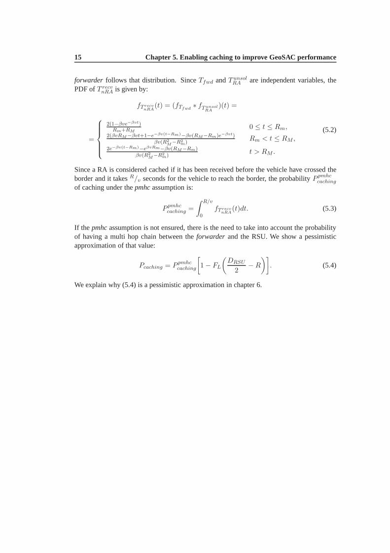
We validate our the proposed models by means of simulation. We develope an ad hocsimulator, that simulates a stretch of roadDRSU meters long, where vehicles travel atv m/sand the distance between them follows (4.2). The area borderis placed half the way (seefigure 6.1).
Figure 6.1: The simulator scheme
We ran simulations changing four different parameters: vehicular speed (v), vehiculardensity (β), time between RA (TRA) and forwarding time (the average time that relays waitbefore forwarding a packet) (Tforw). Many possible values of (Tforw) were considered, butfinally we decided to exclude this parameter from the set. In our model, RAs are consideredto be forwarded as soon as possible, giving to the geocast phase a bursty behavior. Usinghigher values of (Tforw) would have introduced a discrepancy between the model and thesimulation.
Parameter Valuesv 5, 50 ,80 ,120 Km/hβ 10, 20, 40, 50 vehicles/Km
TRA 1, 4, 10, 20, 30 sDRSU 300, 500, 1000, 1500, 2000 m
R 150, 300 m
Table 6.1: The set of parameters used in the simulation runs
16
17 Chapter 6. Model validation and results
Finally, we used values of (Tforw) comparable to a normal delay between hops in a802.11 wireless network (i.e. vehicles do not wait any additional time and forward anyreceived RA immediately). Other parameters that we considered are the distance betweentwo adjacent RSU (DRSU ) and the wireless coverage range of vehicles (R). The set of thevalues given to the parameters is shown in table (6.1) Valuesof Rm andRM are calculatedas 75% and 125% of the value ofTRA. Not all the possibles combinations of values arevalid, because they can create situations that are not feasible in real environments, like veryhigh speed combined with high density. So we focused our attention on possibles scenarios.
0
2
4
6
8
10
0 1 2 3 4 5 6 7 8 9 10
Tco
nf
TRA
speed 80 Km/h β 20 vehicles/km (simulation)(analysis)
speed 50 Km/h β 40 vehicles/km (simulation)(analysis)
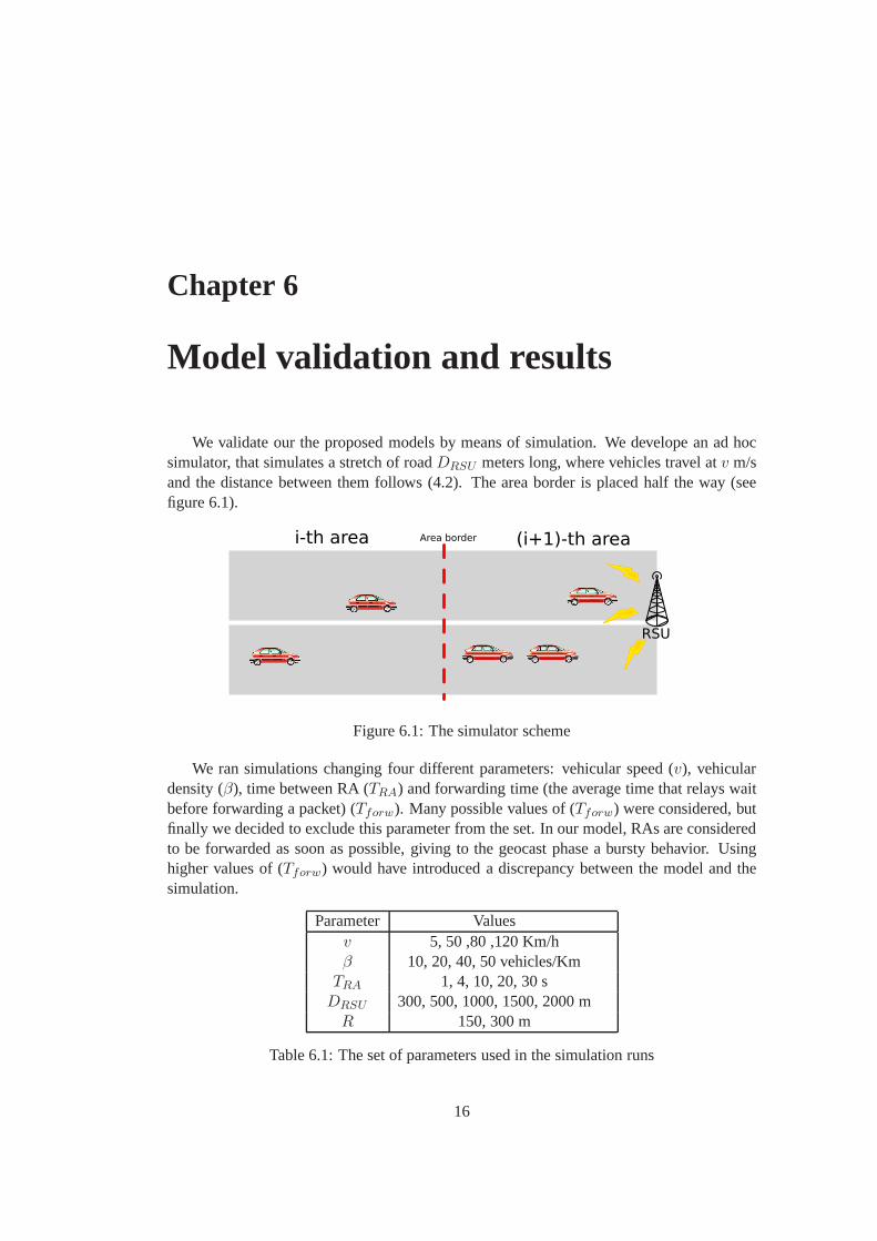
Figure 6.2:Tconf , DRSU =1000mR=150m
In figure (6.2) it is shown the configuration time of vehicles with different values ofTRA, using the standard version of GeoSAC. We can see that our model matches prettyaccurately, floating around the values obtained by simulation. With lower values ofTRA,analytical results fit more tightly the curve coming from thesimulation, because as config-uration opportunities are paced by RA frequency, lower frequencies make our model lessaccurate.
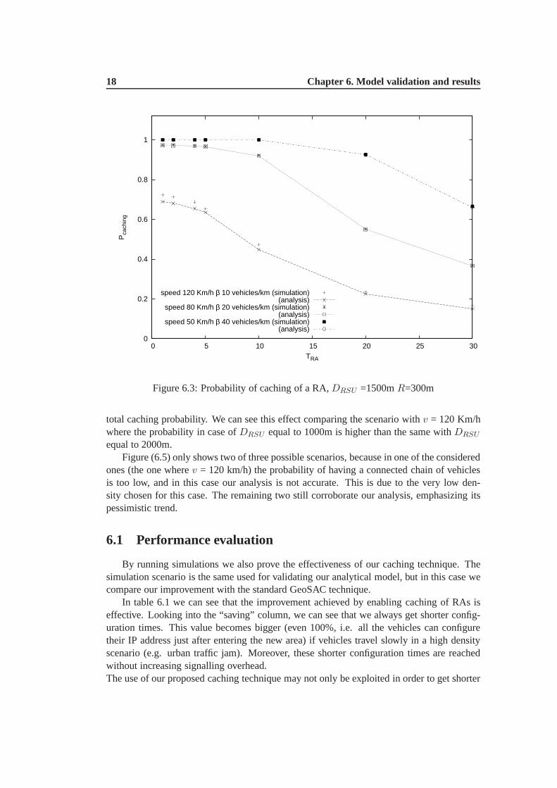
In figure (6.3) it is plotted the caching probability (Pcaching) of an RA against differentvalues ofTRA. We can see that our analysis is always pessimistic. This is because in (5.4)we force the chain length to be at leastDRSU
2 − R, that is the maximum possible value.Moreover, we consider just a single opportunity of receiving an RA from the subsequentarea, while there might be more than one before crossing the area border.
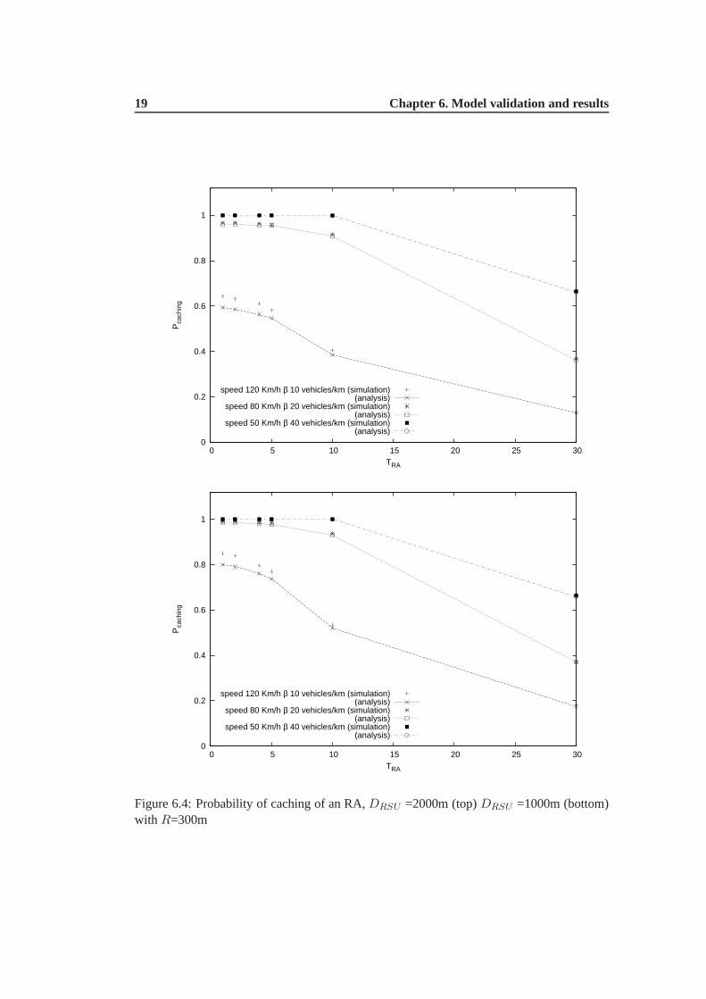
Also figure (6.4) shows that our analysis applies to other scenarios as well. With a shorterdistance between RSUs the probability of having a connectedchain of vehicles arises, so the
18 Chapter 6. Model validation and results
0
0.2
0.4
0.6
0.8
1
0 5 10 15 20 25 30
Pca
chin
g
TRA
speed 120 Km/h β 10 vehicles/km (simulation)(analysis)
speed 80 Km/h β 20 vehicles/km (simulation)(analysis)
speed 50 Km/h β 40 vehicles/km (simulation)(analysis)
Figure 6.3: Probability of caching of a RA,DRSU =1500mR=300m
total caching probability. We can see this effect comparingthe scenario withv = 120 Km/hwhere the probability in case ofDRSU equal to 1000m is higher than the same withDRSU
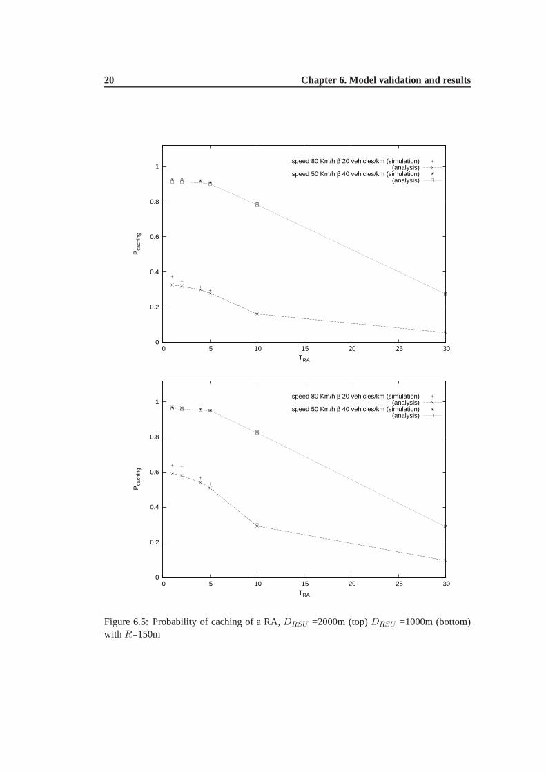
equal to 2000m.Figure (6.5) only shows two of three possible scenarios, because in one of the considered
ones (the one wherev = 120 km/h) the probability of having a connected chain of vehiclesis too low, and in this case our analysis is not accurate. Thisis due to the very low den-sity chosen for this case. The remaining two still corroborate our analysis, emphasizing itspessimistic trend.
6.1 Performance evaluation
By running simulations we also prove the effectiveness of our caching technique. Thesimulation scenario is the same used for validating our analytical model, but in this case wecompare our improvement with the standard GeoSAC technique.
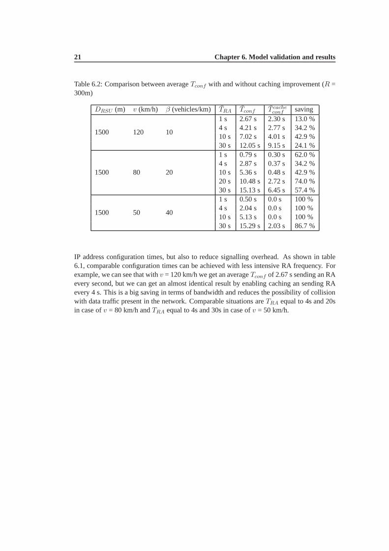
In table 6.1 we can see that the improvement achieved by enabling caching of RAs iseffective. Looking into the “saving” column, we can see thatwe always get shorter config-uration times. This value becomes bigger (even 100%, i.e. all the vehicles can configuretheir IP address just after entering the new area) if vehicles travel slowly in a high densityscenario (e.g. urban traffic jam). Moreover, these shorter configuration times are reachedwithout increasing signalling overhead.The use of our proposed caching technique may not only be exploited in order to get shorter
19 Chapter 6. Model validation and results
0
0.2
0.4
0.6
0.8
1
0 5 10 15 20 25 30
Pca
chin
g
TRA
speed 120 Km/h β 10 vehicles/km (simulation)(analysis)
speed 80 Km/h β 20 vehicles/km (simulation)(analysis)
speed 50 Km/h β 40 vehicles/km (simulation)(analysis)
0
0.2
0.4
0.6
0.8
1
0 5 10 15 20 25 30
Pca
chin
g
TRA
speed 120 Km/h β 10 vehicles/km (simulation)(analysis)
speed 80 Km/h β 20 vehicles/km (simulation)(analysis)
speed 50 Km/h β 40 vehicles/km (simulation)(analysis)
Figure 6.4: Probability of caching of an RA,DRSU =2000m (top)DRSU =1000m (bottom)with R=300m
20 Chapter 6. Model validation and results
0
0.2
0.4
0.6
0.8
1
0 5 10 15 20 25 30
Pca
chin
g
TRA
speed 80 Km/h β 20 vehicles/km (simulation)(analysis)
speed 50 Km/h β 40 vehicles/km (simulation)(analysis)
0
0.2
0.4
0.6
0.8
1
0 5 10 15 20 25 30
Pca
chin
g
TRA
speed 80 Km/h β 20 vehicles/km (simulation)(analysis)
speed 50 Km/h β 40 vehicles/km (simulation)(analysis)
Figure 6.5: Probability of caching of a RA,DRSU =2000m (top)DRSU =1000m (bottom)with R=150m
21 Chapter 6. Model validation and results
Table 6.2: Comparison between averageTconf with and without caching improvement (R =300m)
DRSU (m) v (km/h) β (vehicles/km) TRA Tconf T cacheconf saving
1500 120 10
1 s 2.67 s 2.30 s 13.0 %4 s 4.21 s 2.77 s 34.2 %10 s 7.02 s 4.01 s 42.9 %30 s 12.05 s 9.15 s 24.1 %
1500 80 20
1 s 0.79 s 0.30 s 62.0 %4 s 2.87 s 0.37 s 34.2 %10 s 5.36 s 0.48 s 42.9 %20 s 10.48 s 2.72 s 74.0 %30 s 15.13 s 6.45 s 57.4 %
1500 50 40
1 s 0.50 s 0.0 s 100 %4 s 2.04 s 0.0 s 100 %10 s 5.13 s 0.0 s 100 %30 s 15.29 s 2.03 s 86.7 %
IP address configuration times, but also to reduce signalling overhead. As shown in table6.1, comparable configuration times can be achieved with less intensive RA frequency. Forexample, we can see that withv = 120 km/h we get an averageTconf of 2.67 s sending an RAevery second, but we can get an almost identical result by enabling caching an sending RAevery 4 s. This is a big saving in terms of bandwidth and reduces the possibility of collisionwith data traffic present in the network. Comparable situations areTRA equal to 4s and 20sin case ofv = 80 km/h andTRA equal to 4s and 30s in case ofv = 50 km/h.
Chapter 7
Conclusions and future work
In this thesis we have developed an analytical model for GeoSAC [2], that provides anexpression of the IP address configuration time. Using our model, GeoSAC parameters canbe tuned to fit network requirements in terms of delay or distance between RSUs. We alsoproposed an improvement for GeoSAC based on RA caching. We conclude from resultsthat:
• our caching mechanism is very effective reducing configuration times, as shown intable 6.1.
• this improvement can be used to achieve certain configuration time sending less con-trol messages, hence introducing less signalling overheadon the air, by sending unso-licited RAs less frequently.
In our experiments we always considered inter-vehicular distance following an exponentialdistribution, but in real life environments this may not be always true. Current ongoingwork include the analysis of different vehicle distribution, as well as to deploy a testbed andconducting real experiment to validate our analysis.
22
References
[1] Lee J. Bain and David L. Weeks. A Note on the Truncated Exponential Distribution.The Annals of Mathematical Statistics, 35(3):1366–1367, September 1964.
[2] R. Baldessari, C.J. Bernardos, and M. Calderon. GeoSAC -Scalable address autocon-figuration for VANET using geographic networking concepts.In Proc. IEEE 19th Inter-national Symposium on Personal, Indoor and Mobile Radio Communications PIMRC2008, pages 1–7, 2008.
[3] V. Devarapalli, R. Wakikawa, A. Petrescu, and P. Thubert. Network Mobility (NEMO)Basic Support Protocol. RFC 3963 (Draft Standard), January2005.
[4] Maria Fazio, Claudio E. Palazzi, Shirshanka Das, and Mario Gerla. Automatic IP ad-dress configuration in VANETs. InVANET ’06: Proceedings of the 3rd internationalworkshop on Vehicular ad hoc networks, pages 100–101, New York, NY, USA, 2006.ACM.
[5] F.Templin and S. Russert. MANET Autoconfiguration. Draft Informational, April 2009.
[6] Youn-Hee Han, J. Choi, and Seung-Hee Hwang. Reactive Handover Optimization inIPv6-Based Mobile Networks.Selected Areas in Communications, IEEE Journal on,24(9):1758–1772, Sept. 2006.
[7] T. Narten, E. Nordmark, W. Simpson, and H. Soliman. Neighbor Discovery for IPversion 6 (IPv6). RFC 4861 (Draft Standard), September 2007.
[8] S. Ruffino and P. Stupar. Automatic configuration of IPv6 addresses for MANET withmultiple gateways (AMG). Internet Draft, 2006.
23