Embed Size (px)
Citation preview
t THE SPEED SQUARE
"SPEED LINE"
SW ANSON'S BOOK OF
RAFTER LENGTHS AND
ROOF CONSTRUCTION
Frame Your Roofs as Easily as Your Studdings or Joists
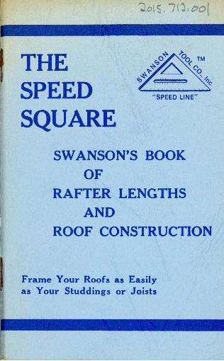
You've got our Square .. Now, Get our Saw Set!
HEAVY
D UTY
SAW
SET
Stop f ighting dull saw blades. Reset the teeth with a
SWANSON SAW SET
Fast and Easy - Right on the Job
(see inside back cover for more detai l)
Write to Swanson Tool Co. for current prices, or ... see your local dealer.
SWANSON TOOL COMPANY, INC. P. 0 . Box 434, Oak Lawn, Illinois 60453
Phone : (312) 599-9029
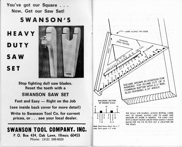
ENLARGED SECTION OF DEGREE SCALE
10 15
• I • I
Nol• : E•d1 hu ... y blod Ii"• i1 1° wide. Eed1 1peu i1 2° wide .
THE SCALE. o.,o DEGREES. ACROSS BOTI0h4 (LONG LEG) OF SQUARE ALLOWS US ER TO ""4ARK AND t,,,1EASURE HIS WORK IN DEGREES. THE LONG LINES WITH A HEAVY BLOCK LINE BETWEEN MAKES IT h4UCH EASIER FOR THE EYE TO PI CK OUT A LOCATION ON
THE SCALE.
THE "ONE NUMBER" METHOD FOR ANY PITCHED ROOF
The one number method developed by the Swanson Tool Co. simplifies roof framing to where roofs are really framed as "easily as your studdings or joists."
Following is a brief description of the various rafters, how to get the different cuts, where to measure from, what is meant by "run" and "rise," information about the hip and valley rafter, etc.
This book has been rewritten with the use of more pictures in the hope it will be of greater benefit to those who are not as familiar with roof construction as the tradesman. Good planning will save time and material.
NOW WITH FULL 90 DEGREE SCALE
The square has been redesigned with the addition of a full 90 degree scale, which will enable the user to mark any angle in degrees, as well as all the angles represented in "inch rise per foot run." You can easily· convert degrees to inch rise or vice versa at a glance. The square makes an excellent guide for the electric saw to run against and is very handy for trim work.
2
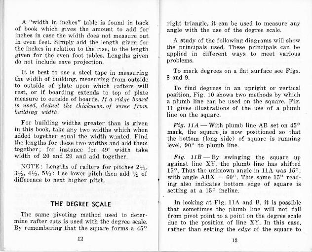
COMMON RAFTER : One running at right angles (90°) from plate to ridge. The common rafter will form the diagonal leg (hypothenuse ) of a 90 ° triangle, with the rise and run forming the 90 ° angle of the triangle ( Fig. 1) .
Fig. 1 also shows correct points from which to measure. Study them and remember the picture when you are on the j ob. Where the arrows show I• Rafter Length •I. these a re the lines to measure from. When your lumber is not straight, always put the crown or high side up when laying out any rafter. When laying out rafter as shown in Fig. 1 ( lets assume 5" rise ), start at top end of rafter. Lay s:i:uare on face of rafter, with "T" bar of s:i:uare down over the edge of rafter. Pivot S1Uare to where number 5 on common scale lines up with same edge of rafter as pivot point. Keep pivot point tight against edge of rafter. Start your mark at pivot point, marking along top edge of square. See drawing in front of book. This gives the top plumb cut, to fit against ridge.
M easure the rafter length along top edge of rafter. Mark another plumb cut same as above. This line represents outside wall of the building. (The same point from which you measu·red the width of the building). Add whatever length you want for a tail or eave to the rafter lengths given in the table in back of book. Mark at end of tail on rafter is plumb
3
cut, same as one at top end of rafter ( Fig. 1 ). The tails of the rafters may be cut on the ground, or wait until rafters are all in place and mark t he ends to a line and cut- what ever is the easiest. To get the Bottom or Heel cut see Fig. 2.
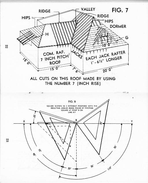
VALLEY RAFTER: One running diagonally from the plate to the ridge at the intersection of gable extension with main roof ( Fig. 7) .
HIP RAFTER : One running diagonally from the plate to t he ridge (Fig. 7).
Since both hip and valley rafters run at a 45° angle to the common rafter, they both represent the diagonal or hypothenuse of a right triangle; the three sides being the h ip, plate and common rafter, or the valley, ridge and common rafter. Therefore, the cuts and lengths apply equally to hip and valley rafters (Fig. 3) .
You will notice the square has a separate Hip-Val Scale which must be used for either of these two rafters. But always use the s a ' )'W
number on Hip-Val scale as you used on t he common rafter scale- the number represen ti ng inch rise. The reason for the separat e Hip-Val scale is that the hip and valley rafters run at 45 ° to the common rafter, and therefore must be longer. In Fig. 3, the hip rafter has a horizontal run of 17" to rise 12", while the
4
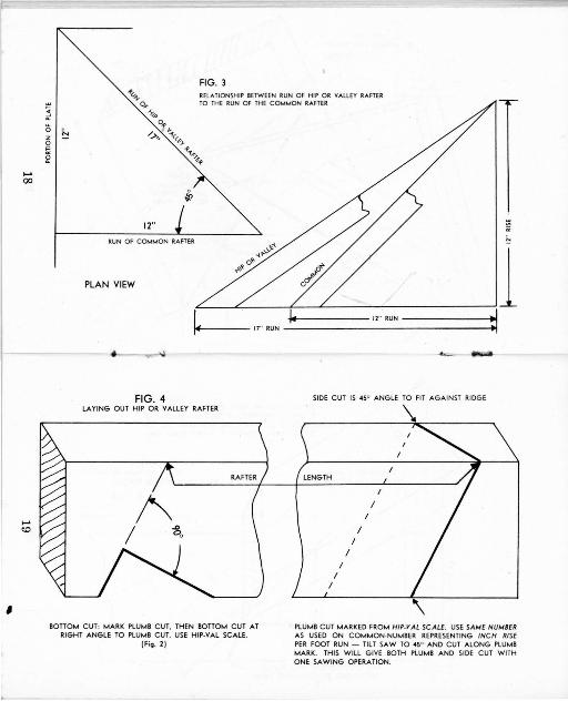
common rafter rises 12" in only 12" of horizontal run. This r equires a different angle for the plumb cuts. In Fig. 4, square is held on r after and pivoted in the same ma nner as wit h a common rafter, but using the Hip-Val scale. If building is out of square, one hip will be cut a little shorter, depending on how great the error is. Keep longer corner at top end of hip u·p even with top of ridge. Keep ridge and hips well propped up until roof boards are nailed. Watch that you don' t put a bow in ridge or hip while nailing other rafters to them.
To find intersection points of center of hips on ridge, leave ridge about a foot too long at point where both hips intersect the ridge. Take a regular length common rafter (such as used on main roof). Set bottom cut over edge of plate and in line with ridge. Make sure your walls are straight. Place top end of common rafter along side of the ridge, bringing top point of common even with top of ridge ( Fig. 5). Mark across top of ridge at this point. This mark is the center line of the two intersecting hips. The common rafter used to get this intersection point would be placed in the same position as the one in Fig. 7 that comes in line with the ridge and runs underneath the little dormer on the 20'0" wall side. This way you know the rise of the hips will be the same as the rise of the common rafter
5
on main roof. Leave the bottom ends of the hi ps (eave end ) a li t tle short so they will :not interfere with lining up the facia boards at the corner.
JA CK RAFTERS: One which does not extend from plate to ridge. Hip Jack - one running from plate to hip at 90 ° to plate. Valley Jack - one running from ridge to valley at 90 ° to ridge. Cripple Jack - one which neither touches the ridge nor plate, but runs from a hip rafter to a valley rafter at 90 ° to the ridge (Fig. 7) .
The rise and run of a jack rafte r are the same as that of a common rafter . When marking jacks use the common rafter scale and same number (inch rise). Where rafter r ests against hip or valley, mark plumb cut. then cut at 45 ° angle along this ma rk. This will give both plumb cut and side cut ( Fig. 4 ). When resting on ridge or plate, lay out the same as for the common rafters. For cripple jacks, mark plumb cu ts on both ends and saw at 45 ° as above.
When measuring the length o'f the jack rafter, measure from longest corner (plumb cut on 45 °) to other plumb cut mark. along Top Side (same as shown in Fig. 4 for hip rafter ) . Cripples are measured from long point to long point diagonally along top edge. Measuring to the long point (Fig. 4) will compen-
6
sate for 1/z of the ridge thickness ( or for jacks, % of valley or hip thickness). There is no problem in laying out these ang les on t he rafters as long as you keep in mind which side of the hip ( or whatever ) you want t he rafter to fit against. Usually a carpenter will space the cei ling joist from an outside wall and working to a 48" cent er. This gives proper spacing for dry wall or panelling 01' wh '.l tever is used. Proper spac ing of ce iling joist wi ll ai d in roof construction. Measure shortest j ack first ( usu ally running next to a ce iling joist ) , from plate to hip rafter. The difference in length of the rest of the jacks is taken from chart. Set each rafter along side cei ling joist and spike well. The ceiling joist then ti es the roof together.
Figure the rafter material lengths so you· can cut a long and short jack rafter from each piece. When you have cut your shortest jack, the angle of the long end will then fit on the other side of the hip. Do this all the way up the hip, always leaving the cut off end for t he other side. If lumber has crown in it, put crown up on longest cut off piece.
In some cases a carpenter will build the valley on top of the main roof, not using a valley rafter. This of course would be the easiest way on any remodeling job , room addition, etc. It saves cutting into and we;1kening the ma in roof. Mark location of valley on
7
roof boards, 45 ° to common rafters (See Dormer , Fig. 7) . Set long point of bottom end of rafter even with this line ("G" of Fig. 7 ). The top cut of t he rafter is the same as top cut of common. Bottom end is a horizontal cut, same as Bottom or Heel cut tr.at fits on top of plate, and is marked in same way, but extends all the way across rafter (Fig. 2 ) . Then ti lt the base of your saw to the same angle as the roof on which the bottom end of the rafter will r est. I.E. , if rafter end is to fit on a roof with 6" rise, you would ti lt the base of saw to an angle of 26% 0 (6" rise) and cut along horizontal line. With saw set at this angle you wi ll see t hat it fits over the pointed end of top of common rafter, because this would also be a 26 % 0 (6" rise) angle. Save the cut off ends for the other side.
Fig. 7 shows a roof as is sometimes used over a door. See "H." To get the pointed end cut, the Square is held in position for the plumb cut of the fiat roof. Then a line running from the pivot corner of the Square thru the number representing the rise of the Main Roof is the cut wanted.
PLYWOOD ROOF SHEATHING When using plywood for a roof sheathing
it is best to do the angle cutting on the horses as follows: from the far left hand corner of a 4 x 8 foot sheet, measure to the right the
8
distance given for the pitch wanted (measurements given in following chart ) . From this point draw a line back to the near left hand corner. These measu·rements are for a perfectly square roof. Better check the firs t piece cut for any changes required.
For roofs of 6" pitch or steeper, the bevel can be cut with an electric saw that tilts to 45 °. For a flatter pitched roof it is best to leave the saw set at 90 ° and use a valley strip made as follows : Scribe a line %" from the right hand edge of a 2" piece. With the saw ti lted, rip at this line. The strip should be the thickness of the roof boards at the thick edge.
Inch R ise Me asure fr o m pe r f oot run c orner o f P lywood
2" 3' 11 %" 2 'h" 3' 11" 3" 3' 10%" 31h" 3' lO Vs " 4" 3' 9%" 4 'h" 3' 9" 5" 3' 8 % " 5 'h " 3' 7 %" 6" 3' 6 'Vs " 7" 3' 5 % " 8" 3' 3 'Vs " 9" 3' 2 %"
10" 3' 'Vs" 11" 2' 11 %" 12" 2' 9 'Vs"
9
FOR UNEVEN PITCHED ROOFS If your roof has no hips or valleys and you
have more than one pitch, cut each section separately using the number representing t he pitch of that section.
For instance, if the front section is 8" rise and 12' run, you would use number 8 and find your rafter lengths under 24' width. Then we'll say the rear is 3" rise and 16' run. Use number 3 on the Square, and 32' bui lding width for your length . The top cut to fit against the ridge is plumb for both sections. Your rear plate would be 4' higher.
DETERMINING THE RISE OF A ROOF Assume your bui lding has an 18' wide span
and you want an 8' rise . Expressed as an equation:
I h . Rise x 12 nc nse per foot run = -=--
Run
The rise here is 8' and the run is 9' ( 1/z of 8 x 12 96
span) so: -9- - = 9 or 10 % " rise. Round
thi~ off !o !he closest inch ( in this case 11" ) , which will increase the rise by 1h " x 9' or 3" for this bui lding. Now you· can look in rafter table under 18' building width and 11" rise and your rafter is 12' 21/z" . This does not include any overhang. If exact length is needed see Fig. 1. (Also Page 12, Note.)
10
A "Full" pitch roof is one having a 24" rise for 12" run. Following is a Table of various pitches. Pitch equals rise divided by span; being the proportion the rise bears to the span.
Inch Run Inch Rise Pitch
12" 22 11 / 12 12" 20 5/6 12" 18 3/4 12" 16 2/3 12" 14 7/ 12 12" 12 1/ 2 - meaning roof 12" 10 5/ 12 rises a distan~e 12" 8 1/3 equal to 1/2 of 12" 6 1/4 building width. 12" 4 1/6 12" 2 1/ 12
USING THE RAFTER LENGTH TABLES
In the following pages are tables giving the lengths of any common, hip or valley rafter for any' pitch up to a 24" rise, and for building widths up to 40 feet. (See Page 12. )
Fig. 7 gives one example of the use of these tables. The main building is 20' wide x 30' long with a 7" rise. Thus, the hip rafters are 15' 3% " long, and the common rafters 11' 7". The 15' x 15' addition, hips and valleys are 11' 5% " long and the commons 8' 8% ". For the 10' Gable Dormer on top of the roof boards, the longest rafters are 5' 91/z".
11
A "width in inches" table is found in back of book which gives the amount to add for inches in case the width does not measure out in even feet. Simply add the length given for the inches in relation to the rise, to t he length given for the even foot tab les. Lengths given do not include eave projection.
It is best to use a steel tape in measu ring the width of building, measuring from outside to outside of plate upon which rafters will rest, or if boarding extends to top of plate measure to outside of boards. If a ridge board is used, deduct the thickness. of same f rom building width.
For building widths greater than is given in this book, take any two widths which when added together equal the width w:rntcd. Find the lengths for these two widths and add them together; for instance for 49' width take width of 20 and 29 and add together.
NOTE: Lengths of rafters for pitches 2112 , 3%, 41/2, 5% : Use lower pitch then add 1/2 of difference to next higher pitch .
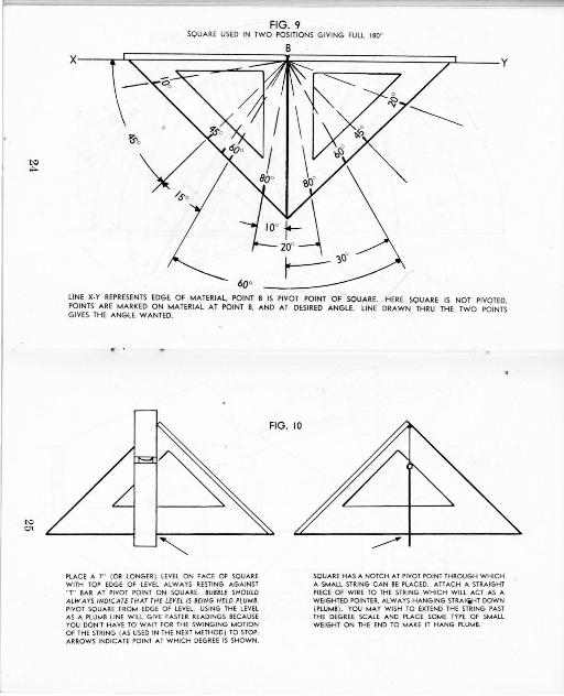
THE DEGREE SCALE
The same pivoting method used to determine rafter cuts is used with the degree scale. By remembering that the square forms a 45 °
12
right triangle, it can be used to measure any angle with the use of the degree scale.
A study of the following diagrams will show the principals used. These principals can be applied in different ways to meet various problems.
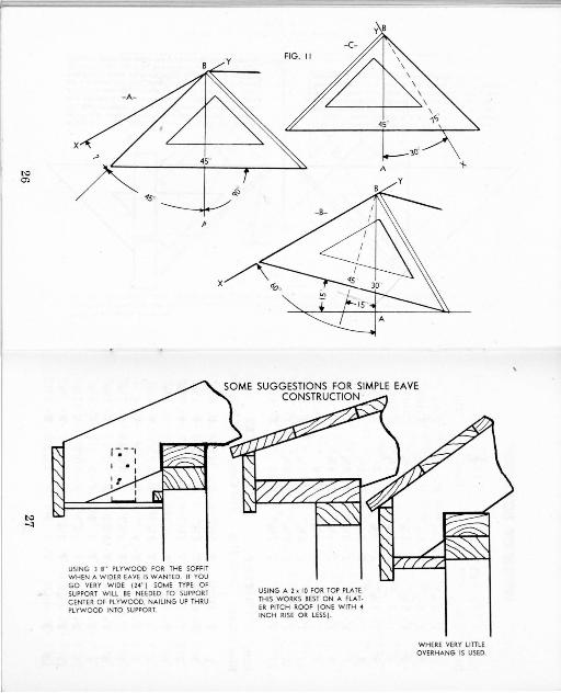
To mark degrees on a flat surface see Figs. 8 and 9.
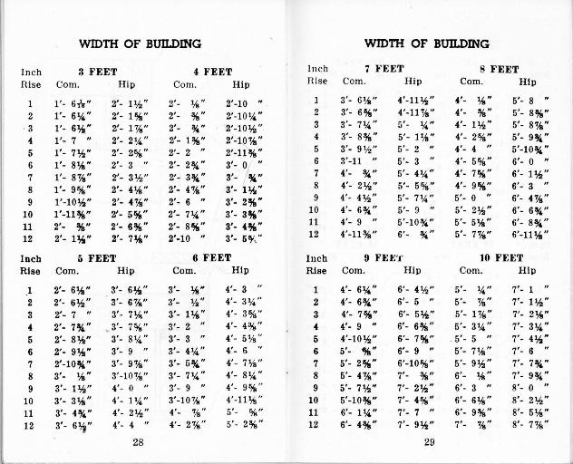
To find degrees in an upright or vertical position, Fig. 10 shows two methods by· which a plumb line can be used on the square. Fig. 11 gives illustrations of the use of a plumb line on the square.
Fig. 11A - With plumb line AB set on 45 ° mark, the square. is now positioned so that the bottom (long side) 0£ square is running level, 90 ° to plumb line.
Fig. 11B - By swinging the square up against line XY, the plumb line has shifted 15 °. Thus the unknown angle in llA was 15° , with angle ABX = 60 ° . This same 15° reading also indicates bottom edge of square is setting at a 15 ° incline.
In looking at Fig. llA and B, it is possible that sometimes the plumb line will not fall from pivot point to a point on the degree scale due to the position of line XY. In this case, rather than setting the edge of the square to
13

line XY, simply turn the square over and let line XY run behind the square. Line XY will then run from pivot point to some point on the degree scale; such as shown in Fig. llC. Now set plumb line AB on square. The number of degrees on scale between plumb line and angle line indicates measured angle.
RAFTER LENGTHS PER FOOT RUN
Seldom does the roof on a house have greater than a 112 pitch, which is a 12" 1·ise per foot run. For a steeper roof, a table is provided which gives any rise from 1" to 24". The figures given are the length per foot run of any given rise. (See table on page 15.) I.E ., assume the roof has a 22" rise per foot run. With a 22" rise, the length per foot run of a common rafter is 25.06 inches. Assume building is 50' wide. The run of the common would be 25' ( 1/z of width). 25 x 25.06 = 626.50 inches. Divide by 12 and you have 52.208 feet or 52' - 21/z" ( .21 x 12 gives you- the 2Yz"). Deduct % thickness of ridge from this length.
Hip or Valley rafter would be figured the same way.
14
Rise
1 2 3 4 5 6 7 8 9
10 11 12 13 14 15 16 17 18 19 20 21 22 23 24
Length of Rafter per Foot Run (In Inches)
Common Rafters
12.04 inches 12.16 12.37 12.65 13.00 13.42 13.89 14.42 15.00 15.62 16.28 16.97 17.69 18.44 19.21 20.00 20.81 21.63 22.47 23.32 24.19 25.06 25.94 26.83
15
Hip-Val Rafters
17.03 inches 17.09 17.23 17.44 17.69 18.00 18.36 18.76 19.21 19.70 20.22 20.78 21.38 22.00 22.65 23.32 24.02 24.74 25.47 26.23 27.00 27.78 28.58 29.39
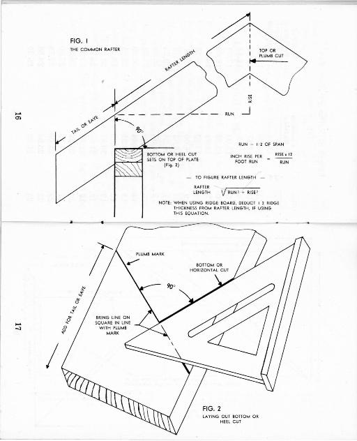
FIG. I d
I
THE COMMON RAFT ER I I
TOP OR PLUMB CUT
...... O>
r \I"-''"
'<,l"-....i.~ 0 ..
--- -~ ... -
...... -:t
I
~ .;r ~
"' .._ ... ~ "' ,§ ...
·v ___ , __ _ " RUN
_J
1~ BOTTOM OR HEEL CUT SETS ON TOP OF PLATE
(Fig. 21
RUN = 1, 2 OF SPAN
INCH RISE PER FOOT RUN
RISE 1 12
RUN
TO FIGURE RAFTER LENGTH
RAFTER LENGTH v RUN l T RISE2
NOTE: WHEN USING RIDGE BOARD, DEDUCT I 2 RIDGE THICKNESS FROM RAFTER LENGTH, IF USING THIS EQUATION.
PLUMB MARK
FIG. 2 LA YING OUT BOTTOM OR
HEEL CUT
'
..... 00
..... <O
FIG. 3 "&,i.. RELATIONSHI P BETWEEN RUN OF HIP OR VALLEY RAFTER
O,(' TO THE RUN OF THE COMMON RAFTER
; ~ IN 0
" 2 ~
-\,A
~ ~(( ~,.
12"
-fl..,-~ ~ ..
b
RUN Of COMMON RAFTER
PLAN VIEW
a,
17"RUN-~~-~
-· FIG. 4
LA YING OUT HIP OR VALLEY RAFTER
BOTTOM CUT: MARK PLUMB CUT, THEN BOTTOM CUT A T RIGHT ANGLE TO PLUMB CUT. USE HIP-VAL SCALE.
(F;g. 21
~ ........
SIDE CUT IS 45° ANGLE TO FIT AGAINST RIDGE
LENGTH
I I
I
I I
I
\
I
\ PLUMB CUT MARKED FROM HIP-YAL SCALE. USE SAME NUMBER AS USED ON COMMON-NUMBER REPRESENTING INCH RISE PER FOOT RUN - TILT SAW TO 45° ANO CUT ALONG PLUMB MARK. THIS WILL GIVE BOTH PLUMB AND SIDE CUT WITH ONE SAWING OPERATION.
t'O 0
t'O ......
MARK SHOWING THE CENTER LINE OF THE TWO INTERSECTING HIPS
RIDGE
FIG. 5 FINDING INTERSECTING POINTS OF HIPS ON RIDGE
.-=,,,.
CUT RIDGE ABOUT 2" LONGER THAN MARK, SO YOU CAN NAIL THRU RIDGE INTO H IP -PROVIDING NO CENTER COMMON RAFTER IS USED. IF ONE IS USED RIDGE MUST BE CUT AT TH IS MARK.
\ / 1/
~ ~
~
--~~~Ii JJ jO~~;; 0
nmZ r~OOv, 0,.
~5;:o)> ~
~i~~~ (j)V> -. (j)
o~E!! I o~I~ -~ -no~~ n On~,... c oIO~
1 ';11, r - )>I.,., )> ~ (j) =uo -<o~~s ~,--~O~
~~;~~ ~~~z~ !IO~z ~o:~~
IQ~o m z ~ "TI
: ;--! )> ~ )> ~.,.,)> -n IC~ -;-1;::;;:::~
N) N)
N) c,:,
FIG. 7
~·· · 11 ~ coM. RAI""· I -""Jc' t . I I I I C\( R.t·J·iER
/6', 7 \NCH p\iCH -ts EACH ~/~ LONGER o ;, ROOF \ • - b :z.
~ ·o·· ~ Is ->, ,.,0· o·· ~,,~ I,.
ALL CUTS ON THIS ROOF MADE BY USING THE NUMBER 7 (INCH RISE)
FIG. ·9
SQUARE SHOWN IN l DIFFERENT POSITIONS WITH THE RESULTING ANGLES BEING FOUND BY PIVOTING
SQUARE AT POINT 8 ON UNE X-Y
y
N> .,..
N> 01
FIG. 9 SQUARE USED IN TWO POSITIONS GIVING FULL 180°
x i ~ i y f'( ' - ---~ - 7
!lo " ~y
/.So
600
LINE X-Y REPRESENTS EDGE OF MATERIAL, POINT B IS PIVOT POINT OF SQUARE. HERE SQUARE IS NOT PIVOTED. POINTS ARE MARKED ON MATERIAL AT POINT B, AND AT DESIRED ANGLE. LINE DRAWN THRU THE TWO POINTS GIVES THE ANGLE WANTED.
PLACE A 7" (OR LONGER ) LEVEL ON FACE OF SQUARE WITH TOP EDGE OF LEVEL ALWAYS RESTING AGAINST " T" BAR AT PIVOT POINT ON SQUARE. BUBBLE SHOULD ALWAYS INDICATE THAT THE LH'EL IS BEING HELD PLUMB. PIVOT SQUARE FROM EDGE OF LEVEL USING THE LEVEL AS A PLUMB LINE WILL GIVE FASTER READINGS BECAUSE YOU DON'T HAVE TO WAIT FOR THE SWINGING MOTION OF THE STRING (AS USED IN THE NEXT METHOD ) TO STOP. ARROWS INOICA TE POINT AT WHICH DEGREE IS SHOWN.
-------SQUARE HAS A NOTCH AT PIVOT POINT THROUGH WHICH A SMALL STRING CAN BE PLACED. ATIACH A STRAIGHT PIECE OF WIRE TO THE STRING WHICH Will ACT AS A WEIGHTED POINTER, ALWAYS HANGING STRAl(iHT DOWN (PLUMB) . YOU MAY WISH TO EXTEND THE STRING PAST THE DEGREE SCALE ANO PLACE SOME TYPE OF SMALL WEIGHT ON THE END TO MAKE IT HANG PLUMB.
N> cr,
N> ...:,
4S•
"
USING 3 8" PLYWOOD FOR THE SOFFIT WHEN A WIDER EAVE IS WANTED. IF YOU GO VERY W IDE (24 ") SOME TYPE OF SUPPORT WILL BE NEEDED TO SUPPORT CENTER OF Pl YWOOO. NAILING UP THRU PLYWOOD INTO SUPPORT.
°'"'
USING A 2 1 10 FOR TOP PLATE. THIS WORKS BEST ON A FLATER PITCH ROOF (ONE WITH <4
INCH RISE OR LESS).
i-
W HERE VERY LITTLE OVERHANG IS USED.
wmm OF Bun.DING wmm OF Bun.DING
Inch 3 FEET 4 FEET Inch 7 }'EET 8 FEET
Rise Com. Hip Co m. Hip ni se Com. Hip Com. Hip
1 1·- 6nr" 2'- Ph " 2'- 1k .. 2'-10 H 1 3'- 61111" 4'-11¥.z" 4'- 1Ai,, 5'- 8 ,,
2 1'- 6l4." 2'- 1%" 2'- %" 2'-1014" 2 3'- 6%" 4'-117/s" 4'- %" 5'- 8%"
. 3 1'- 6%." 2'- 1 7/s" 2'- *" 2'-10¥.z" 3 3'- 714" 5' - 14 H 4'- 1¥.z" 5'- 87/s"
4 1'- 7 ,, 2'- 2~" 2'- 1%" 2'-107/s" 4 3'- 8%" 5'- PA." 4'- 2%" 5'- 9%"
1'- 7¥.z" 2'- 2%" ,,
2'-11%" 5 3'- 91h " 5'- 2 ,, 4'- 4 ,,
5'-10%" 5 2'- 2 ,, 2'- 2%"
,, 6 3'-11 " 5'- 3 " 4'- 5%" 6'- 0 ,, 6 1'- 81,s" 2'- 3 3'- 0 7 1'- 87/s" 2'- 31h" 2'- 3% H 3'- %" 7 4'- %" 5'- 414" 4'- 7%" 6'- 11h"
1'- 9%" 2'- 4%" 2'- 47/s" 3'- 1~" 8 4'- 2¥.z" 5'- 5%" 4'- 9%" 6'- 3 " 8 ,, 3'- 2%" 9 4'- 41h" 5'- 71,4" 5'- 0 ,,
6'- 47/s" 9 1'-101h" 2'- 47/s" 2'- 6 1'-11%" 2'- 5%" 2'- 714" 3'- 3%" 10 4'- 6%" 5'- 9 ,, 5'- 21h" 6'- 6%" 10
2'- 6%" 2'- 8%" 3'- -i%" 11 4'- 9 ,, 5'-10%" 5'- 51,s" 6'- 8%" 11 2'- %"
12 2'- l'Ai" 2'- 7%" 2'-10 ,, 3'- 6 1f ." 12 4'-11%" 6'- %" 5'- 7%" 6'-11%"
Inch o FEET 6 FEET Inch 9 FEt:'J.' 10 FEET Rise Com. Hip Com. Hip Rise Com. Hip Com . Hip
1 2'- 61,s" 3'- 6%" 3'- 1Ai" 4'- 3 .. 1 4'- 614" 6'- 41h" 5'- 14" 7'- 1 ..
2 2'- 61h" 3'- 6%" 3'- ~~,, 4'- 314" 2 4'- 6%" 6'- 5 ,, 5'- %" 7'- 11h" 3 2'- 7 .. 3'- 7~" 3'- 1%" 4' - 3%" 3 4'- 7%" 6'- 51h" 5'- 17/s" 7'- 21A," 4 2'- 7%" 3'- 7%" 3'- 2
,, 4'- 4%" 4 4'- 9 H 6'- 6%" 5'- 314" 7'- 314"
5 2'- 81h" 3'- 814" 3'- 3 ,, 4'- 51/s " 5 4'-10¥.z" 6'- 7%" . 5'- 5 ,, 7'- 41h"
6 2'- 91h" 3'- 9 ,, 3'- 414" 4'- 6 .. 6 5'- %" 6'- 9 ,, 5'- 71111" 7'- 6
,,
7 2'-10%" 3'- 9%" 3'- 6%" 4'- 71/s" 7 5'- 2%" 6'-10%" 5'- 91h" 7'- 7%" 8 3'- 1Ai,, 3'-107/s" 3'- 71,4" 4'- 81,4" 8 5'- 4%" 7'- %" 6'- %" 7'- 9%" 9 3'- 11h" 4'- 0 ,, 3'- 9 " 4'- 9% " 9 5'- 7¥.z" 7'- 21h" 6'- 3 ,, 8'- 0
,,
10 3'- 31k" 4'- 114." 3'-107/s" 4'-11% " 10 5'-10%" 7'- 4%" 6'- 61,s" 8'- 21h"
11 3'- 4%" 4'- 21h" 4'- 7/s,, 5' - %" 11 6'- 114" 7'- 7 ,, 6'- 9%" 8'- 51,s" 12 3'- 6~ " 4'- 4 ,, 4'- 27/s" 5'- 2%" 12 6'- 4%" 7'- 91h" 7'- 7/s,, 8'- 7%"
28 29
wmrn OF Bun.DING WIDTH OF BUil.DING
Inch 11 FEET 12 FEET Inch 15 FEET 16 FEET
Rise Com. Hip Com. Hip Rise Com . Hip Com. Hip
1 5'- 614" 7'- 91h" 6' · 14" 8'- 6 " 1 7'- 614" 10'- 71h" 8' - %" 11'- 4 .. 2 6'- 7 .. 7'-10 " 6'- 1 .. 8'- 61h" 2 7'- 714" 10'- 8%" 8'- 1%" 11'- H~" 3 5'- 8 .. 7'-10%" 6'- 214" 8'- 7%" 3 7'- 8%" 10'- 914" 8'- 3 " 11'- 5%" 4 5'- 9%" 8'- 0 .. 6'- 3%" 8'- 8%" 4 7'-10%" 10'-10%" 8'- 514" 11'- 71h " 6 5'-111h" · 8'- 1%" 6'- 6 .. 8'-101.4" " 5 8'- 1¥.," 11 '- *" 8'- 8 11'- 9%" 6 6'-1%" 8'- 3 .. 6' - 81,," 9'- 0 ..
6 8'- 4%" 11 '- 3 " 8'-111h" lll' - 0 .. 7 6'- 41h" 8'- 4%" 6'-11%" 9'- 21,i," 8 6'- 7%" 8'- 71,i," 7'- 21h" 9'- 4%"
7 8'- 8%" 11'- 5%" 9'- 314" 12'- 2%"
9 6'-101h" 8'- 9%" 7'- 6 .. 9'- 71,4" 8 9' - 14" 11'- 8*" 9'- 7%" 12'- 61AJ"
10 7'- 2 .. 9' - % '' 7'- 9%" 9'-101,4" 9 9'- 4¥.," 12'- 1,1i " 10'- 0 .. 12'- 9%"
11 7'- 61h" 9'- 314" 8'- 1%" 10'- 1%" 10 9'- 914" 12'- H~" 10'- 5 .. 13'- 1%"
12 7'- 9%# 9'- 614" 8'- 6%" 10'- 4%" 11 10'- 2%" 12'- 7*" 10' -10 14" 13'- 5%"
Inch 18 FEET H FEET 12 10'- 7%" 12'-11 %" 11 '- 3*" 13' -1014"
Rise Com. Hip Com. Hip Inch 17 FEET 18 FEET
1 6'- 61,4" 9'- 21,," 7'- 1,4" 9'-11 .. Rise Com. Hip Com. H ip
2 6'- 71Ai" 9'- 3 " 7'- 11,i," 9'-11%" 1 8'- 6')s" 12'- 1h" 9'- %" 12'- 9 .. 3 6'- 81,," 9'- 4 " 7'- 2%" 10'- %" 2 8'- 7¥.i" 12 '- 114" 9' - 11h" 12'- 9%"
4 6'-1014" 9'- 6%" 7'- 4,ii" 10'- 2%" 3 8' - 91Ai" 12'- 21h" 9'- 3%" 12' -11 IAI "
6 7'- ,ii" 9'- 7%" 7'- 7 " 10'- 3%" 4 8'-11%" 12'- 414" 9'- 5%" 13' - 1 .. 6 7'- 31,4" 9'- 9 .. 7'-10 .. 10'- 6 .. 5 9'- 21h" 12'- 6¥.," 9'- 9 .. 13'- 3%"
7 7'- 6%" 9'-111.4" 8'- 1%" 10'- 81,," 6 9'- 614" 12' - 9 .. 10'- %" 13'- 6 "
8 7'- 9%" 10'- 2 .. 8'- 6 .. 10'-11%" 7 9'-10 14" 13'- 0 .. 10'- 51Ai" 13'- 914"
9 8'- ~,ii" 10'- 4)ia" 8'- 9 .. 11'- 21,," 8 10'- 2%" 13'- 31h" 10'- 9%" 14'- %"
10 8'- 6%" 10'- 81,ii" 9'- 1%" 11'- 6~" 9 10'- 71h" 13'- 714" 11'- 3 .. 14'- 4%"
11 8'- 9%," 10'-11%" 9'- 6 " 11'- 9%" 10 11'- %" 13' -ll 1h" 11'- 8%" 14··- 9%"
12 9'- 2%" 11'- 3 " 9'-10%" 12'- 1,ii" 11 11'- 61h" 14' - 4 .. 12'- 2¥.i " 15'- 2 .. 12 12'- l"-,, 14'- 8%" 12'- 8*" 15' - 7 ..
30 31
-----
WIDnl OF Bun.DING WIDnl OF Bun.DING Inch 21 FEET 22FEET
Inch 19 FEET ii> FEET Rise Com. Hip Com. Hip Rise Com. Hip Com. Hip
1 10'- 6%" H'-101il" 11'- %" 16'- 7 ,,
1 9'- 6%" 13'- 61h" 10'- %" H'- 2 " 2 10'- 7"" 1''-11%" 11'- 1%" 15'- 8 ,,
2 9'- 7%" 13'- 6%" 10'- 1%" H'- 2%" 3 10'-10 ,, 16'- 1 . 11'- 4%" 16'- 91il"
3 9'- 9%" 13'- 7%" 10'- 3%," 14' - 4-%" • 11'- %" 16'- 3%" 11'- 7%" 16'-11%" 4 10'- 14" 13'- 9%" 10'- 61h" H'- 6%" 6 11'- 41il" 16'- 6%" 11'-11 ,. 16'- 2%,. 6 10'- 3%" H'- 14 .. 10'-10
,, H'- 9 ,,
6 11'- 9 ,, 16'- 9 ,.
12'- 3%" 16'- 6 ,,
6 10'- 7%" H'- 3 ,, 11'- 21,4" 16'- 0 ,.
7 12'- 2 ,.
16'- %" 12'- 8%" 16'-10 ,.
7 11'- %" ·'
H'- 6%" 11'- 7 " 16' - 3%" 8 12'- 7%" 16'- 6 ,.
13'- 2~" 17'- 2%" 8 11'- 6 " H'-101.4" 12'- 1.4" 16'- 7%" 9 13'- 11,{i" 16'- 9%" 13'- 9
,, 17'- 7%"
9 11'-101,{i" 16'- 21,{i" 12'- 6 ,. 16'- %" 10 13'- 8 ,,
17'- 2%" H'- 3%" 18'- %"
10 12'- 41,{i" 16'- 71.4" 13'- 1.4,, 16'- 6 " 11 H'- 3 ,,
17'- 8%" H'-11%H 18'- 61,{i"
11 12'-10%" 16'- %" 13'- 6%" 16'-10%" Inch 28 }'EET 24 FEET 12 13'- 61,4" 16'- 6%" H'- 1%," 17'- 3%" Rise Com. Hip Com. Hip 13 H'- 1.4,, 16'-11 " H'- 9
,. 17'- 9%" 1 11'- 6%" 16'- 31h" 12'- %" 17'- 0 "
H H'- 71.4" 17'- 6 " 16'- 4%" 18'- 4 ,,
2 11'- 7%" 16'- 41h" 12'- 1 %" 17'- 1%" 16 16'- 21,{i" 17'-11%" 16'- %" 18'-101,{i"
3 ll'-10%" 16'- 6%" 12'- 41h" 17'- 2~" 16 16'-10
,. 18'- 61,{i" 16'- 8
,, 19'- 61,4" 4 12'- 1%" 16'- 8%" 12'- 7%" 17'- 614"
17 16'- 6%" 19'- 1.4,, 17'- 4%" 20'- 14,, 5 12'- 5%" 16'-11%" 13'- 0 " 17'- 8%" .
18 17'- 1%" 19'- 7 ,, 18'- 14" 20'- 7%" 6 12'-10%" 17'- 3 " 13'- 6 " 18'- 0 "
19 17'- 91,{i" 20'- 2 " 18'- 8%," 21'- 2%" 7 13'- 3%" 17'- 7%" 13'-10%" 18'- 4%"
20 18'- 6%" l!IO'- 91,4" 19'-61,4" 21'-10%" 8 13'- 9%" 17'-11%" 14'- 6 " 18'- 9%"
21 19'- 1%" 21'- H1" 20'- 1%" 22'- 6 ,,
9 14'- 41h" 18'- 5 " 15'- 0 " 19'- 21h"
22 19'-10%" 22'- 0 ,.
20'-10%" 23'- 1%" 10 14'-11 %" 18'-10%" 15'- 7%" 19'- 8%"
23 20'- 6%" 22'- 7%" 21'- 7%" 23'- 9%" 11 15'- 7%" 19'- 4%" 16'- 3%" 20'- 2%" 12 16'- 3%" 19'-11 " 16'-11%" 20'- 9%"
24 21'- 2%" 28'- 31,4" 22'- 4%" U'- 6 ,,
32 33
wmra OF Bun.DING WIDTH OF Bun.DING Inch 25 FEET 26 FEET Inch 29 FEET 30 FEET
Rise Com. Hip Com. Hip Rise Com. Hip Com. Hlo
12'- 6%" 17'- 8%" 13'- 18'- 5 " 14'- 6% 11 20'- 61h" 15' - %" 21'- 3 II
1 1h"
2 12'- 8 " 17'- 9%" 13'- 21ifi" 18'- 61;4" 2 14'- 8% 11 20'- 7%" 16'- 2%" 21'- 4 11 %
17'-11%" " 3 14'-11%" 20'- 9% 11 15'- 51h" 21'- 61h"
3 12'-10%" 13'- 4%" 18'- 8 4 15'- 31h" 21'- %" 15'- 9%" 21'- 9%"
4 13'- 2%" 18'- 2 " 13'- 8%" 18'-10% 11
" 5 16'- 8%" 21'- 4%, H 16'- 3 22'- 11h" 5 13' - 61h" 18'- 514" 14'- 1 II 19'- 2%" 6 16'- 2% 11 21'- 9 " 16'- 914 11 22'- 6 " 6 13'-11%" 18'- 9 II 14'- 6%" 19'- 6 II
7 16'- 9%" 22'- 2%" 17'- 41h" 22'-11% II 7 14'- 5%" 19'- 11h" 15'- %" 19'-10% 11 8 17'- 61ifi" 22'- 8 " 18'- *II 23'- 6%"
8 15'- 14" 19'- 672 11 15'- 7¥.i" 20'- 3% 11 9 18'- 11h" 23'- 2%" 18'- 9 .. 24'- 1ifi"
9 15'- 71h" 20'- %" 16'- 3 " 20'- 9%" 10 18'-10%" 23'- 9%" 19'- 6%"' 24'- 71h"
11 19'- 8 II 24'- 61;4" 20'- 41;4 H 25'- 3%" Inch 27 FEET j!J8 FEET
Rise Com. Hip Com. Hip Inch 31 FEE1.' 32 1'' EET
Rise Co m. Hip Com. Hip 1 13' - 6%" 19'- 11h" 14'- %" 19'-10
,, 1 15'- 6%" 21'-ll'h" 16'- %" 22'- 8 "
2 13'- 81;4" 19'- 2% H 14'- 214 11 19'-1114 II 2 15'- 81h" 22'- %" 16' - 2%" 22'- 91h 11
3 13'-11 " 19'- 4%" 14'- 514 11 20' - 11,4" 3 15'-11%" 22'- 31ifi 11 16'- 5%" 22'-11%" 4 14'- 2%" 19'- 71h" 14'- 9%" 20'- 4%" 4 16'- 4%." 22'- 6%" 16'-10%" 23'- 3 " 6 14'- 7%" ) 9'-11 H 16'- 2 ,, 20'- 7%" 5 16'- 91h 11 22'-10%" 17'- 4 II 23'- 7%,"
6 16'- 1 H 20'- 3 .,
16'- 7%" 21'- 0 II 6 17'- 4 " 23'- 3 " 17'-10%" 24'- 0 "
7 16'- · 7%" 20'.- 7%" 16'- 2% 11 21'- 6 II 7 17'-11¥.! 11 23 '- 81h" 18'- 6%" 24'- 5%"
8 16'- 2% H 21'- ll.4 11 16'- 9% 11 21'-10%" 8 18'- 7%" 24'- 2*" 19'- 2%" 25'- 'Ai" ll 19 - 4¥,i" 24'- 9~ 20'- 0 " 25'- 7%"
9 16'-101h" 21'- 7% 11 17'- 6 ,,
22'- 6 II
10 20'- 214" 25·- 5%" 20'-10 II 26'- 314" 10 17'- 7 II 22'- 2 II 18'- 2% 11 22'-11 %"
11 21'- %11 26'- 1¥.i" 21 ·- 81h 11 26'-11%" 11 18'- 3%" 22'- 9 II 18'-11 %" 23'- 72,ii" " 12 21'-11 26'-101,ii" i2'- 7¥,i" 27'- 8%" 12 19'- 11Ai." 2~·- 4¥.i 11 19'- 9% 11 24'- 3 "
34 35
WIDTH OF BUll.DING
Inch 33 FEET Rise Com.
1 16'- 6%" 2 16'- 8%" 3 17' - 0 " 4 17'- 4%" 5 17'-101h" 6 18'- 5%" 7 19'- 1%" 8 19'-10 " 9 20'- 71h"
10 21'- 5%" 11 22'- 4%" 12 23' - 4 " 13 24'- 41/s" 14 25'- 414"
Hip
23'- 4%" 23'- 6 " 23'- 814" 23'-11%" 24'- 41/s" 24'- 9 " 25'- 2%" 25'- 91h" 26'- 6 27'- :'Vs" 27'- 9 ~ .. 28'- 6%" 29'- 4%" 30'- 3 "
Inch Rise
35. FEET
1 2 3 4 [i
G 7 8 9
10 11 12 13 14
Com. Hip
17'- 6%" 17'- 8%" 18'- %" 18'- 5%" 18'-ll)h" 19'- 6%" 20'- 3:Ys" 21'- %" 21'-1072'' 22'- 9%" 23'- 8%" 24'- 9 " 25'- 9%" 26'-10%"
24'- 91h" 24'-11 " 25'- ll).i" 25'- 51,4"
· 25'- 9%" 26'- 3 " 26'-10 1,.C 27'- 41,4" 28' - 14 .. 28'- 8%" 29'- 5%" 30'- 3%" 31'- 1 %" 32'- 1 "
36
34 l'EET Com.
17'- %" 17'- 2%" 17'- 614" 17'-11 " 18'- 5 " 19'- %." 19' - 8%" 20 '- 51/s" 21'- 3 " 22'- 11h" 23'- iii" 24'- %" 25'- %" 26'- 11h"
Hip
24'- 1 " 24'- 21h" 24'- 4%" 24'- 81h" 25'- iii" 25'- 6 " 26'- %" 26'- 6iii" 27'- 2%" 27'-10%" 28'- 7%" 29'- 514" 30'- 314" 31' - 2 "
36 l'EET Com.
18'- %" 18'- 2-Vs" 18'- 6%" 18'-11 %" 19' - 6 " 20'- 11h" 20'-10 14" 21'- 71h" 22'- 6 " 23'- 51/s" 24'- 5 " 25'- 51h" 26'- 6%" 27'- 77,,s"
Hip
25'- 6 " 25'- 7%" 25 '-101/s" 26'- 1 %" 26'- 6%" 27'- 0 " 27'- 6%" 28'- 1%" 28'- 9%" 29'- 6%" 30'- 4 " 31'- 2 " 32'- %" 33'- 0 "
WIDTH OF BUll.DING
Inch 37 FEET Rise Com.
1 18'- 6%" 2 18'- 9 " 3 19'- %" 4 19'- 6%" 5 20'- 1h" 6 20'- 814" 7 21'- 614" 8 22'- 2%" 9 23'- 11h"
10 24'- 1 " 11 25'- 1%" 12 26'- 2 " 13 27'- 31,i," H 28'- 5%"
Hip
26'- 21,i" 26'- 4%" 26'- 6%" 26'-10%" 27'- 31h" 27'- 9 " 28'- 3%" 28'-11 " 29'- 7%" 30'- 41h" 31'- 21,i," 32'- %" 32'-1114" 33'-11 "
Inch Rise
39 FEET
1 2 3 4 5 6 7 8 9
10 11 12 13 14
Com.
19'- 6%" 19'- 9%" 20'- 1%'' 20'- 6%" 21'- 11h" 21'- 9%" 22'- 71,i," 23'- 514" 24'- 41h" 25'- 4%" 26'- 51h" 27'- 7 " 28'- 91i" 29'-11 Iii,"
Hip
27'- 71,i" 27'- 914" 28'- 0 " 28'- 41,ii" 28'- 914" 29'- 3 " 29'-10 " 30'- 5%" 31'- 2%" 32'- 14" 32'-1014" 33'- 914" 34'- 8%" 35'- 9 "
37
SS FEET Com.
19'- % " 19'- 3 " 19'- 7 " 20'- %" 20'- 7 " 21'- 3 " 22'- lh" 22'-10 " 23'- 9 " 24'- 8%" 25'- 9%" 26'-10%" 28'- %" 29'- 2%"
Hip
2~'-11 " 27'- %" 27'- 3%" 27'- 7%" 28'- %" 28'- 6 " 29'- %" 29'- 81h" 30'- 5 . " 31'- 2%" 32'- lh" 32'-10%" 33'-10 " 34'-10 "
40 FEET Com.
20'- %" 20'- 3%" 20'- 7%" 21'- 1 " 21'- 8 " 22'- 4%" 23'- 2 " 24'- %" 25'- 0 " 26'- %" 27'- 1%" 28'- 3%" 29'- 6 " 30'- 87Ai"
Hip
28'- 4 " 28'- 5%" 28'- 8%" 29'- %" 29'- 6 " 30'- 0 " 30'- 714" 31'- 314" 32'- 14" 32'-101,i," 33'- 8%" 34'- 7%" 35'- 7%" 36'- 8 "
AMOUNT TO ADD FOR l TO 11 INQI
Bun.DING WIDffl COM. RAF.
Rise 1 2 3 4 5 6 7 8 9 10 11
t }111 1 1% 2 2% 3% 3% 4% 4% 5% 5%
4 % 1% 1% 2% 2% 31,4 3%. 414 4%. 51,4 5% 5 % 1% 1% 21,4 2%. 314 3%. 4% 4% 5% 5% 6 % 1% 1% 214 2%. 31,4 3%. 4% 4% 5% 6 7 % 1% 1% 2% 3 3% 4 4% 514 5%. 6% 8 % 11.4 1%. 2% 3 3% 4% 4%. 5% 6 6% 9 % 11,4 1% 2% 3% 3%, 4% 5 5% 61,4 6%
10 % 1% 2 2% 31,4 3% 4% 5% 5% 6% 7% 11 %. 1% 2 2% 3% 4% 4% 5% 6% 6%. 7% 12 %. 1% 2% 2%. 3% 41,4 5 5% 6% 7 7%. 13 %. 11h 21,4 3 3% 4% 51,a 6 6% 7% 81,a 14 % 1% 2% 3% 3% 4% 5% 61,4 6% 714 8% 16 %. 1% 2% 31,4 4 4% 5% 6lni 71,4 8 8% 16 % 1% 2lni 3% 4% 5 5%. 6% 7lni 814 9% 17 % 1% 2% 3!ni 41,4 5% 6 7 7% 8% 9% 18 % 1%., 2%. 3% 4% 5% 6% 714 8% 9 10 19 ~ 1 % 2% 3%. 4% 6!ni 6lni 714 8'% 9% 1014 20 1 2 3 4 5 5% 6% 7% 8%. 9% 10% 21 1 2 3 4 5 6 7 8 9 10% 11% 22 1 2 3% 4% 5% 61,4 714 8% 9% 10% 11% 23 11,a 2% 31,4 41,4 6% 6% 71h 8% 9% 10%. 11% 24 1% 21,4 3% 4% 6% 6% 7% 9 10 111.4 12% 26 114 2% 3% 4%. 6 7% 8% 91ni 10% 11 % 13% 28 114 2!ni 3% 51,s 6% 7% 8% 10% 11% 12.% 14 30 1% 2% 4 6% 6%,• 8 91h 10% 12% 13% 14%.
38
AMOUNT TO ADD FOR l TO 11 INCH
wmm OF BUILDING HIP RAF.
Inch Rise 1 2 3 4 5 6 7 8 ll 10 11
1 % 1% 21,{i 2% 3% 414 4% 5o/s 6% 7 7% 2 % 1% 21,a 2% 3% 414 5 5% 6% 71,{i 7% 3 % 1% 214 2% 3% 4% 5 5% 6% 714 7% 4 % 1% 214 3 3% 4% 5% 5% 61h 714 8 5 %. 11h 214 3 3% 4% 51,{i 5% 6% 7% 81,{i 6 %. •1% 214 3 3% 41h 514 6 6% 71h 814 7 % 11h 214 3 3% 4% 5% 61,{i 6% 7% 8% 8 % 11h 2% 31,s 3% 4% 51h 514 7 7% 8% 9 %. 1% 2% 314 4 4% 5% 6% 714 8 87/s
10 % 1% 2% 3% 41,s 4% 5% 6% 7% 814 9 11 7/s 1% 21h 3% 414 5 57/s 67/s 71h 8% 914 12 7/s 1% 2% 31h 4% 514 6 67/s 7% 8% 91h 13 7/s 1%. 2% 3% 4% 5% 6% 714 77/s 87/s 9% 14 7/s 17/s 2% 3% 4% 5% 6% 7% 814 914 101/s 15 1 2 27/s 37/s 4%, 5% 6% 7% 81h 9% 10% 16 1 2 3 4 5 57/s 6% 7% 8% 9% 10 % 17 1 2 3 4 5 6 7 8 9 10 11 18 1 2 3 4 514 61,{i 714 814 914 10% 11% 19 1 21/s 314 414 514 6% 7% 8% 91h 10% 11% 20 l1h 214 314 4% 51h 61h 7% 8% 97/s 107/s 12 21 11,s 214 3% 4% 5% 6% 77/s 9 101,ii 1114 12% 22 114 2% 31h 4% 57/s 7 814 914 10% 11% 12% 23 114 2% 3% 4% 6 714 &% 9% 10% 117/s 13% 24 114 2% 3% 47/s 6% 7% 81h 9% 11 1214 131h 26 114 2% 37/s 514 6% 7% 9 10% 11 % 127/s 1414
39
DIFFERENCE IN LENGTH OF JACK
RAFTERS OF VARIOUS SPACING
Rise 16"
1'- 4Jg" 1'- 41,4" 1' - 41h" l'- 4%" 1'- 5%" 1'- 5%" 1'- 6112" 1'- 71,4" 1'- 8 " l'- 8%" 1'- 9%" l'-10%" 1'-11%" 2'- 1h" 2'- 1%" 2'- 2%" 2'- 3%" 2'- 4%" 2'- 6 " 2'- 7%" 2'- 814" 2'- 9%" 2'-10%" 2'-11%" 3'- 214" 3'- 41h" 3'- 7 "
18" 20" 24"
1 2 3 4 5 6 7 8 9
10 11 12 1~ 14 15 16 17 18 19 20 21 22 23 24 26 28 30
1'- 6%" 1'- 61,4" 1'- 61h" 1'- 7 " 1'- 71h" 1'- 8%" l'- 8 'Vs" l '- 9%" 1'-101h" 1'-11%" 2'- %" 2'- 11h" 2'- 21h" 2'- 3%" 2'- 4%"· 2'- 6 " 2'- 71,4"
2'- 81h" 2'- 9%" 2'-11 " 3' - 1.4" 3'- 1%" 3'- 3 " 3'- 41,4" 3'- 7 " 3'- 9%" 4'- 1h"
40
l'- 8%" 1'- 81,4" 1'- 8%" 1'- 9%" 1'- 9%" 1'-10%" 1'-il1/s" 2'- 0 " 2'- 1 " 2'- 2 " 2'- 3%" 2'- 41,4"
2'- 51h" 2'- 6%" 2'- 8 " 2'- 9%" 2'-10%" 3'- 0 " 3'- 1112" 3'- 2%" 3'- 41,4"
3'- 5%" 3'- 71,4"
3'- 8%" 3'-11 %" 4'- 2%" 4'- 57,i."
2'- 1/s" 2'- %" 2'- %" 2'- 1%" 2'- 2 " 2'- 2%" 2'- 3%" 2'- 4%" 2'- 6 " 2'- 714" 2'- 8%" 2'-10 " 2'-11%" 3'- %" 3'- 2%" 3'- 4 " 3'- 5%" 3 - 71,4" 3'- 9 " 3'-10%" 4'- %" 4'- 2%" 4'- 3%" 4'- 5%" 4'- 9%" 5' - %" 5'- 4%"
THE SWANSON SAW SET . . . .
in just a few minutes time w ill reset the teeth on any general use type comb ination blade (approx. 7 / 16" or more point to point of tooth) . Wide handle holds blade stiff, removing any spring from blade as you set tooth. Narrow handle is placed over tooth to be set (as shown above) and pressed down against adjusting screw to the amount of set des·ired. Wide handle has a larger slot for heavy table saw blades .
Made of strong aluminum alloy. Saves time and money. A practical "on the job" saw set at a reasonable price . Has instructions for setting and sharpening . (File not included).
MARKING EDGE OR SIDE CUT First, mark the proper PLUMB CUT (A).
At right angles to plumb mark, measure a distance equal to thickness of rafter (X) and mark another plumb line. From this plumb line, square across top edge of rafter. Dotted line connects two points, and gives SIDE CUT. This would be the method used for "hand sawing". When using the electric saw, tilt the saw to cut a 45° angle, then cut along the plumb mark. Lay out and cut one rafter, and use it as a pattern to mark the rest.
SWANSON TOOL COMPANY, INC. P. 0. Box 434, Oak Lawn, Illinois 60453
Phone : (312) 599-9029