Embed Size (px)
Citation preview
NEW EPSON ActionPC 5000, ActionTower 5000
speed light power lightpower light hard diskhard disk drive baysdrive bays reset buttonreset button
Idiskette drive button
/-\
inlet AC outlet MOUSE COM2 VGA
power
power light
speed light
hard diskaccess light
drive bays
PARALLEL
COM1
MOUSE
Km
AC Inlet
option skits
A C & l e t \ voltage switch
Computer Specifications
CPU and Memory
32-bit CPU 486SX/25 or /33; SX2/50 or /66;DX/33, /40, or /50; DX2/50 or /66;DX4/75 or /100; or Pentium™OverDrive™processor
Green PCenergy saver
Energy Star compliant, low-power,standby mode for the hard disk drive andvideo signals sent by the computer to themonitor; select timeout periods in SETUP;in a standard configuration of one harddisk drive and one diskette drive, systemconsumes less than 30 watts in standbymode
System speed Fast and slow processor speeds available;fast is the speed of your processor andslow is 8 MHz; 0 wait state memory accessat fast speed
Press Ctrl Alt and - to select slow speed orCtrl Alt and + to select fast speed
Memory
ROM
Video RAM
Shadow RAM
Memoryrelocation
4MB or 8MB RAM standard on a SIMM;expandable to 64MB using 1MB, 2MB,4MB, 8MB, 16MB, and 32MB SIMMs;SIMMs must be tin-plated, 72-pin, 32-bitor 36-bit, fast-page mode type with anaccess speed of 70ns or faster
128KB Phoenix@ system BIOS, video BIOS,and SETUP program located in EPROMon main system board
1MB DRAM on main system board;expandable to 2MB using eight,4 x 4 x 256, 20-pin DIP chips
Supports shadowing of system and videoBIOS ROM into RAM
Supports relocation of 256KB of memoryfrom A0000h to BFFFFh and D0000h toEFFFFh to extended memory
8/94 NEW EPSON ActionPC 5000, ActionTower 5000 - 1
NEW EPSON ActionPC 5000, ActionTower 5000
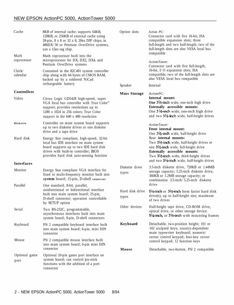
Cache
Mathcoprocessor
Clock/calendar
Controllers
Video
Diskette
Hard disk
Interfaces
Monitor
Parallel
Serial
Keyboard
Mouse
Optional gameport
8KB of internal cache; supports 64KB,128KB, or 256KB of external cache using28-pin, 8 x 8 or 32 x 8, 20ns DIP chips; in486DX/50 or Pentium OverDrive systems,use a 15ns tag chip.
Math coprocessor built into themicroprocessor for DX, DX2, DX4, andPentium OverDrive systems
Contained in the 82C491 system controllerchip along with 64 bytes of CMOS RAM,backed up by a soldered NiCadrechargeable battery
Cirrus Logic GD5428 high-speed, superVGA local bus controller with True Color”support; provides resolutions up to1280 x 1024 in 256 colors; True Colorsupport in the 640 x 480 resolution
Controller on main system board supportsup to two diskette drives or one diskettedrive and a tape drive
Energy Star compliant, high-speed, 32-bitlocal bus IDE interface on main systemboard supports up to two IDE hard diskdrives with built-in controller; BIOSprovides hard disk auto-sensing function
Energy Star compliant VGA interface forfixed or multi-frequency monitor built intosystem board; 15-pin, D-shell connector
One standard, 8-bit, parallel,unidirectional or bidirectional interfacebuilt into main system board; 25-pin,D-shell connector; operation controllableby SETUP option
Two RS-232C, programmable,asynchronous interfaces built into mainsystem board; 9-pin, D-shell connectors
PS/2 compatible keyboard interface builtinto main system board; 6-pin, mini DINconnector
PS/2 compatible mouse interface builtinto main system board; 6-pin mini DINconnector
Optional 10-pin game port interface onsystem board; can control joy-stickfunctions with the addition of a portconnector
Option slots
Speaker Internal
Mass Storage ActionPC:Internal mount:
Diskette drivetypes
Hard disk drivetypes
Other devices
Keyboard
Mouse
Action PC:Connector card with five 16-bit, ISAcompatible expansion slots; threefull-length and two half-length; two of thefull-length slots are also VESA local buscompatible
ActionTower:Connector card with five full-length,16-bit, I/O expansion slots; ISAcompatible; two of the full-length slots arealso VESA local bus compatible
One 3%~inch wide, one-inch high driveExternally accessible mounts:One 3 &nch wide, one-inch high driveand two 5%+inch wide, half-height drives
ActionTower:Front internal mount:One 3*h-inch wide, half-height driveRear internal mounts:Two 3%+inch wide, half-height drives orone 31/1-inch wide, full-height driveExternally accessible mounts:Two 31&inch wide, third-height drivesand two 5’/4-inch wide, half-height drives
3.5-inch diskette drive, 720KB or 1.44MBstorage capacity; 5.25-inch diskette drive,360KB or 1.2MB storage capacity; orcombination 3.5-inch/5.25-inch diskettedrive
5!&inch or 3lh-inch form factor hard diskdrive(s), up to half-height size; maximumof two drives
Half-height tape drive, CD-ROM drive,optical drive, or other storage device;5%nch, or 3%nch with mounting frames
Detachable, two-position height; 101 or102 sculpted keys; country-dependentmain typewriter keyboard; numeric/cursor control keypad; four-key cursorcontrol keypad; 12 function keys
Detachable, two-button, PS/2 compatible
2 - NEW EPSON ActionPC 5000, ActionTower 5000 8/94
NEW EPSON ActionPC 5000, ActionTower 5000
SETUP Stored in ROM; accessible by pressing F2Program during boot
System security User and Supervisor level passwords(8 characters) available for system boot ordiskette access
Virus protection Write protection feature for the hard diskdrive boot sector; periodic remindermessage for running virus detection utility
Physical CharacteristicsDimensionWidthDepthHeight
ActionPC16.8 inches (427 mm)15.8 inches (401 mm)4.4 inches (112 mm)
ActionTower7.125 inches (181 mm)16.25 inches (413 mm)13.25 inches (337 mm)
1 Weight
*
1 17.4 pounds (7.9 kg)*
With one diskette drive, without keyboard
1 16.7 pounds (7.6 kg)* 1
Power SupplyType 200 Watt, UL/TUV/CSA listed, fan-cooled
Input ranges 90-130 VAC or 180-260 VAC;switch-selectable
Maximum +5 VDC at 20 Amps, -5 VDC at 0.5 Ampsoutputs +12 VDC at 8 Amps, -12 VDC at 0.5 Amps
Frequency 47 to 63Hz
Cables Two to main system board, five to massstorage devices; for more than fivedevices, Y cables can be installed on theexisting cables
Option slot power limits
Output Voltage (MC) I +5 Volts -5 volts +12 volts -12 vottsFor all slots I 12 A m p s I0.4~mp I4.0~mps I0.4Amp
Environmental Requirements
ConditionTemperature
Non-operatingOperating range range Storage range41° to 90°F -4° to 140°F -4° to 140°F
1 (5° to 32° C) 1 (-20° to 60° C) 1 (-20° to 60° C) 11 Humidity I 20% to 90% I 10% to 90% 10% to 90% I1 (non-condensing) I1 Altitude
Maximum wet bulb
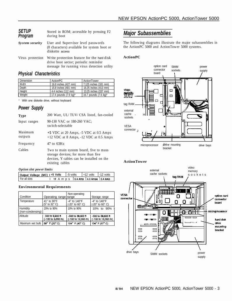
Major Subassemblies
The following diagrams illustrate the major subassemblies inthe ActionPC 5000 and ActionTower 5000 systems.
ActionPC
option card SIMM powerconnector sockets supplyboard I I
socketstag RAM
externalcache - Hsockets
*
VESA
J r -
0connector 1
microprocessor drive mounting drive baysbracket
ActionTower
externalcache sockets
\
videomemorys o c k e t s
drive baysSIMM sockets power
supply
8/94 NEW EPSON ActionPC 5000, ActionTower 5000 - 3
NEW EPSON ActionPC 5000, ActionTower 5000
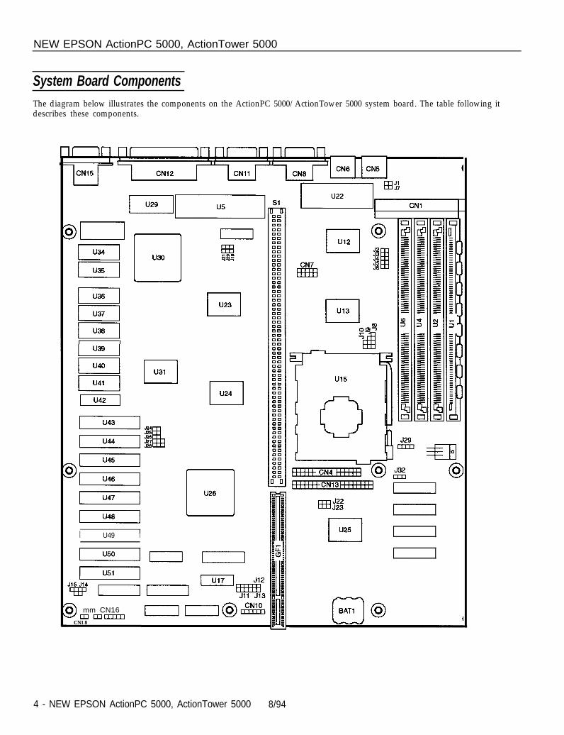
System Board ComponentsThe diagram below illustrates the components on the ActionPC 5000/ActionTower 5000 system board. The table following itdescribes these components.
nrnnnnnnn
I II I
I U49 I
9 mm CN16mmcmn
CN18
4 - NEW EPSON ActionPC 5000, ActionTower 5000 8/94
NEW EPSON ActionPC 5000, ActionTower 5000
components External cache jumper settingsSocket I componentU1, U2, U4, I SIMM socketsU6U5U12, U13
Keyboard/mouse controllerSuper I/O controller (UMC82C863,865); supports up to twodiskette drives. two serial pods, and one parallel port
U15 Microprocessor (ZIF socket)U17 Clock generator: 4V to 7V operating supply range, 1 ns skew.
Cirrus Logic video controller (GD5428); local bus VGA withC, dual-frequency synthesizer, BltBLT
CN111 header1 Serial port labeled COM2: 9-pin. D-shell
Jumper Settings
Miscellaneous jumper settingsJumpernumberJ2
Jumpersetting1-2*
FunctionAssigns COM2 serial port as COM2
1 2-3 1 Assigns COM2 serial port as COM4J3 1-2* 1 Assigns COM1 serial port as COM1
J4
J5
J6
J15
J19
2-31-2*2-31-2*2-31-2*2-3on*
OfflOff*
Assigns COM1 serial port as COM3Assigns PARALLEL port as LPT1Assigns PARALLEL port as LPT2Enables optional game portDisables optional game portEnables diskette drive controllerDisables diskette drive controllerSelects VESA slot running at 1 waft statesSelects VESA slot running at 0 wait state
1 Disables IRQ9 for VGA
~
SETUP values to their factory defaults)j 1-4 1 Selects external battery
Cache size* J24 J25 J26 J27 J28
64KB On Off Off 1-2 Off128KB On On Off 2-3 2-3256KB On On On 1-2 1-2
l *If you have no external cache installed, the position of these jumpers does notmatter.
Processor clock jumper settings
DX2/66, DX4/100, or
l Change these jumpers only if you upgrade your processor.
Processor type jumper settingsProcessor* J8 J9 J10
486SX/SX2 2-3 Open Open487SX/Pentium OverDrive 1-2,3-4 2-3 Open486DX/DX2/DX4 1-2,34 1-2 Open
* Change these jumpers only If you upgrade your processor.
Processor voltage jumper settingsProcessor voltage J29 J325 volt 1-2 and 3-4 (not used for 5-Volt processor)3.3 and 3.45 Volt 5-6 and 7-8 1-23.6 Volt 5-6 and 7-8 3-4
Note: To determine the voltage of your processor, see page 6.
SVGA jumper settingsVGA jumper functionEnable on-hoard VGADisable on-board VGA
J20 J21On OnOff off
PS/2 mouse jumper settingsJumper functionEnable PS/2 mouse supportDisable PS/2 mouse support
J1 J72-3 2-31-2 1-2
8/94 NEW EPSON ActionPC 5000, ActionTower 5000 - 5
NEW EPSON ActionPC 5000, ActionTower 5000
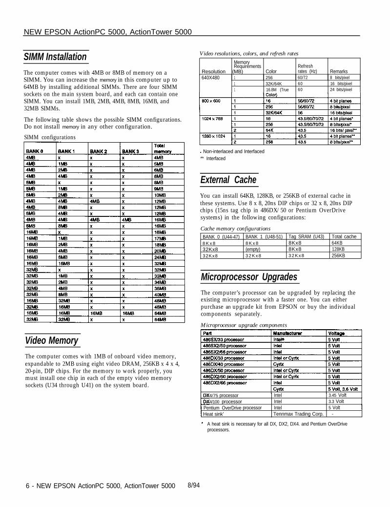
SIMM Installation
The computer comes with 4MB or 8MB of memory on aSIMM. You can increase the memory in this computer up to64MB by installing additional SIMMs. There are four SIMMsockets on the main system board, and each can contain oneSIMM. You can install 1MB, 2MB, 4MB, 8MB, 16MB, and32MB SIMMs.
The following table shows the possible SIMM configurations.Do not install memory in any other configuration.
SIMM configurations
Video Memory
The computer comes with 1MB of onboard video memory,expandable to 2MB using eight video DRAM, 256KB x 4 x 4,20-pin, DIP chips. For the memory to work properly, youmust install one chip in each of the empty video memorysockets (U34 through U41) on the system board.
Video resolutions, colors, and refresh rates
MemoryRequirements Refresh
Resolution (MB) Color rates (Hz) Remarks640X480 1 256 60/72
1 32K/64K 601 16.8M (True 60
8 bits/pixel16 bits/pixel24 bits/pixel
l Non-interlaced and Interfaced** Interfaced
External Cache
You can install 64KB, 128KB, or 256KB of external cache inthese systems. Use 8 x 8, 20ns DIP chips or 32 x 8, 20ns DIPchips (15ns tag chip in 486DX/50 or Pentium OverDrivesystems) in the following configurations:
Cache memory configurationsBANK 0 (U44-47) BANK 1 (U48-51) Tag SRAM (U43) Total cache8 K x 8 8 K x 8 8Kx8 64KB32Kx8 (empty) 8Kx8 128KB32Kx8 3 2 K x 8 3 2 K x 8 256KB
Microprocessor Upgrades
The computer’s processor can be upgraded by replacing theexisting microprocessor with a faster one. You can eitherpurchase an upgrade kit from EPSON or buy the individualcomponents separately.
Microprocessor upgrade components
4/75 processor Intel 3.45 Volt4/100 processor Intel 3.3 Volt
1 Pentium OverDrive processor Intel 5 Volt1 Heat sink’ I Tennmax Trading Corp. -
A heat sink is necessary for all DX, DX2, DX4. and Pentium OverDriveprocessors.
6 - NEW EPSON ActionPC 5000, ActionTower 5000 8/94
NEW EPSON ActionPC 5000, ActionTower 5000
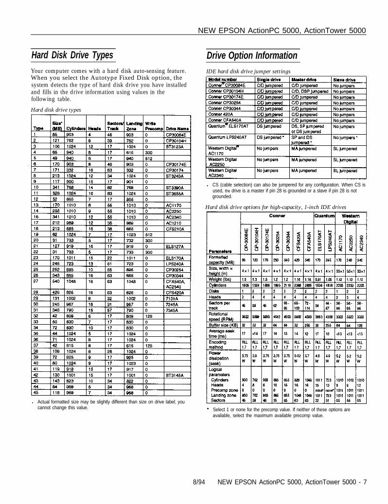
Hard Disk Drive Types Drive Option InformationYour computer comes with a hard disk auto-sensing feature.When you select the Autotype Fixed Disk option, thesystem detects the type of hard disk drive you have installedand fills in the drive information using values in thefollowing table.
IDE hard disk drive jumper settings
Hard disk drive types
l Actual formatted size may be slightly different than size on drive label; youcannot change this value.
l CS (cable selection) can also be jumpered for any configuration. When CS isused, the drive is a master if pin 28 is grounded or a slave if pin 28 is notgrounded.
Hard disk drive options for high-capacity, 1-inch IDE drives
Select 1 or none for the precomp value. If neither of these options areavailable, select the maximum available precomp value.
8/94 NEW EPSON ActionPC 5000, ActionTower 5000 - 7
NEW EPSON ActionPC 5000, ActionTower 5000
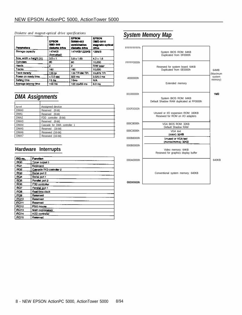
Diskette and magnet-optical drive specifications
DMA AssignmentsLevel
DMA0DMA1DMA2DMA3DMA4DMA5DMA6DMA7
Assigned deviceReserved (8-bit)Reserved (8-bit)FDD controller (8-bit)Reserved (8-bit)Cascade for DMA controller 1Reserved (16-bit)Resewed (16-bit)Resewed (16-bit)
Hardware Interrupts
System Memory Map
FFFFFFFFFh
System BIOS ROM: 64KBDuplicated from 0F0000h
FFFFF0000h
Resewed for system board: 64KBDuplicated from 0E0000h
4000000h
Extended memory
64MB(Maximum
systemmemory)
001000000h
System BIOS ROM: 64KBDefault Shadow RAM duplicated at FF0000h
OOOFOOOOh
Unused or I/O expansion ROM: 160KBResewed for ROM on I/O adapters
000C8000h
000C0000h
VGA BIOS ROM: 32KBDefault Shadow RAM
VGA text
000B8000h
000B0000h
Video memory: 64KBResewed for graphics display buffer
000A0000h 640KB
Conventional system memory: 640KB
8 - NEW EPSON ActionPC 5000, ActionTower 5000 8/94
NEW EPSON ActionPC 5000, ActionTower 5000
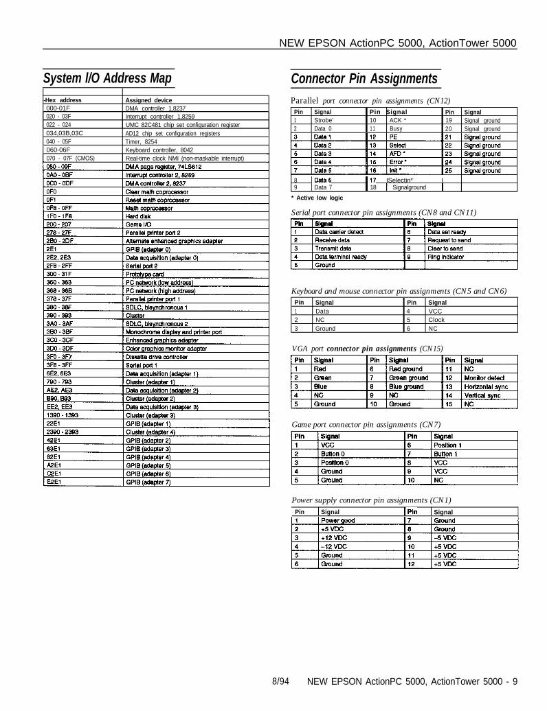
System l/O Address Map Connector Pin AssignmentsParallel port connector pin assignments (CN12)
Pin Signal Pin Signal Pin Signal1 Strobe’ 10 ACK * 19 Signal ground2 Data 0 1 1 Busy 20 Signal ground
-Hex address000-01F020 - 03F022 - 024034,03B,03C040 - 05F060-06F
Assigned deviceDMA controller 1,8237interrupt controller 1,8259UMC 82C481 chip set configuration registerAD12 chip set configuration registersTimer, 8254Keyboard controller, 8042
070 - 07F (CMOS) I Real-time clock NMI (non-maskable interrupt) 1
8 IData 117 ISelectin* I9 I Data 7 1 18 I Signalground 1
* Active low logic
Serial port connector pin assignments (CN8 and CN11)
Keyboard and mouse connector pin assignments (CN5 and CN6)Pin Signal Pin Signal1 Data 4 VCC2 NC 5 Clock3 Ground 6 NC
VGA port connector pin assignments (CN15)
Game port connector pin assignments (CN7)
Power supply connector pin assignments (CN1)Pin I Signal [Pin I Signal
8/94 NEW EPSON ActionPC 5000, ActionTower 5000 - 9
NEW EPSON ActionPC 5000, ActionTower 5000
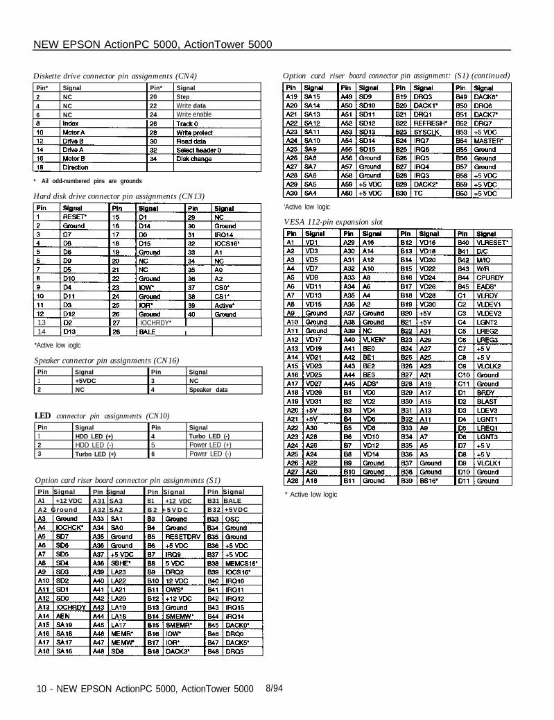
Diskette drive connector pin assignments (CN4) Option card riser board connector pin assignment: (S1) (continued)Pin*
2
46
Signal
NC
NCNC
Pin*20
2224
SignalStep
Write data
Write enable
* Ail odd-numbered pins are grounds
Hard disk drive connector pin assignments (CN13)
13 ID214 ID13
*Active low ioglc
127 1 IOCHRDY* 1128 IBALE I
Speaker connector pin assignments (CN16)Pin Signal Pin Signal1 +5VDC 3 NC2 NC 4 Speaker data
LED connector pin assignments (CN10)Pin Signal Pin Signal1 HDD LED (+) 4 Turbo LED (-)2 HDD LED (-) 5 Power LED (+)3 Turbo LED (+) 6 Power LED (-)
Option card riser board connector pin assignments (S1)Pin Signal Pin Signal Pin Signal Pin SignalA1 +12 VDC A31 SA3 B1 +12 VDC B31 BALEA2 Ground A32 SA2 B 2 + 5 V D C B32 +5VDC
‘Active low logic
VESA 112-pin expansion slot
* Active low logic
10 - NEW EPSON ActionPC 5000, ActionTower 5000 8/94
NEW EPSON ActionPC 5000, ActionTower 5000
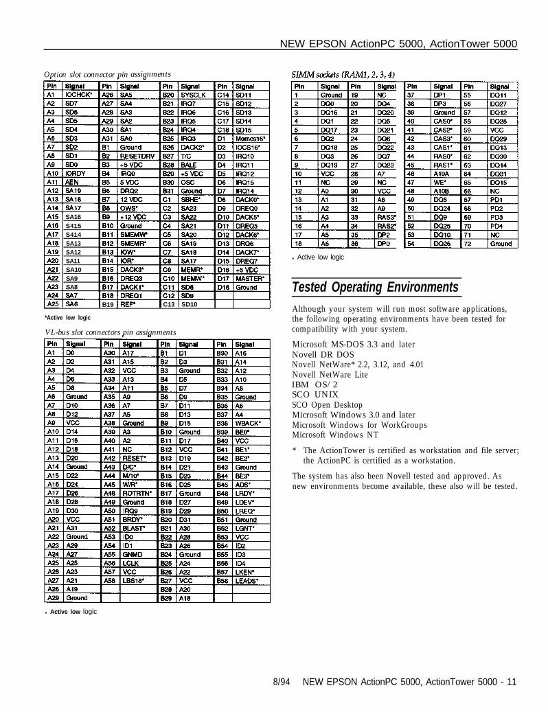
Option slot connector pin assignments
SA16
S415S414SA13SA12SA11SA10SA9SA8
IA25 IS48 1 B19 1 C13 1 SD10 I 1*Active low logic
VL-bus slot connectors pin assignments
l Active low logic
l Active low logic
Tested Operating EnvironmentsAlthough your system will run most software applications,the following operating environments have been tested forcompatibility with your system.
Microsoft MS-DOS 3.3 and laterNovell DR DOSNovell NetWare* 2.2, 3.12, and 4.01Novell NetWare LiteIBM OS/2SCO UNIX SCO Open DesktopMicrosoft Windows 3.0 and laterMicrosoft Windows for WorkGroupsMicrosoft Windows NT
* The ActionTower is certified as workstation and file server;the ActionPC is certified as a workstation.
The system has also been Novell tested and approved. Asnew environments become available, these also will be tested.
8/94 NEW EPSON ActionPC 5000, ActionTower 5000 - 11
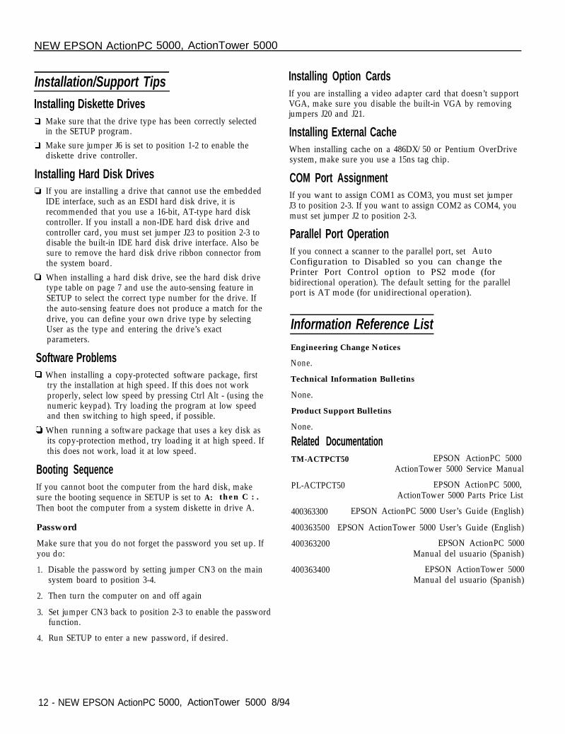
Software ProblemsCl When installing a copy-protected software package, first
try the installation at high speed. If this does not workproperly, select low speed by pressing Ctrl Alt - (using thenumeric keypad). Try loading the program at low speedand then switching to high speed, if possible.
D When running a software package that uses a key disk asits copy-protection method, try loading it at high speed. Ifthis does not work, load it at low speed.
Booting SequenceIf you cannot boot the computer from the hard disk, makesure the booting sequence in SETUP is set to A: then C : .Then boot the computer from a system diskette in drive A.
Password
Make sure that you do not forget the password you set up. Ifyou do:
1. Disable the password by setting jumper CN3 on the mainsystem board to position 3-4.
2. Then turn the computer on and off again
3. Set jumper CN3 back to position 2-3 to enable the passwordfunction.
4. Run SETUP to enter a new password, if desired.
Installation/Support Tips
Installing Diskette DrivesP Make sure that the drive type has been correctly selected
in the SETUP program.
Cl Make sure jumper J6 is set to position 1-2 to enable thediskette drive controller.
Installing Hard Disk DrivesIf you are installing a drive that cannot use the embeddedIDE interface, such as an ESDI hard disk drive, it isrecommended that you use a 16-bit, AT-type hard diskcontroller. If you install a non-IDE hard disk drive andcontroller card, you must set jumper J23 to position 2-3 todisable the built-in IDE hard disk drive interface. Also besure to remove the hard disk drive ribbon connector fromthe system board.
When installing a hard disk drive, see the hard disk drivetype table on page 7 and use the auto-sensing feature inSETUP to select the correct type number for the drive. Ifthe auto-sensing feature does not produce a match for thedrive, you can define your own drive type by selectingUser as the type and entering the drive’s exactparameters.
NEW EPSON ActionPC 5000, ActionTower 5000
12 - NEW EPSON ActionPC 5000, ActionTower 5000 8/94
Installing Option CardsIf you are installing a video adapter card that doesn’t supportVGA, make sure you disable the built-in VGA by removingjumpers J20 and J21.
Installing External CacheWhen installing cache on a 486DX/50 or Pentium OverDrivesystem, make sure you use a 15ns tag chip.
COM Port AssignmentIf you want to assign COM1 as COM3, you must set jumperJ3 to position 2-3. If you want to assign COM2 as COM4, youmust set jumper J2 to position 2-3.
Parallel Port OperationIf you connect a scanner to the parallel port, set AutoConfiguration to Disabled so you can change thePrinter Port Control option to PS2 mode (forbidirectional operation). The default setting for the parallelport is AT mode (for unidirectional operation).
Information Reference List
Engineering Change Notices
None.
Technical Information Bulletins
None.
Product Support Bulletins
None.
Related DocumentationTM-ACTPCT50 EPSON ActionPC 5000
ActionTower 5000 Service Manual
PL-ACTPCT50 EPSON ActionPC 5000,ActionTower 5000 Parts Price List
400363300 EPSON ActionPC 5000 User’s Guide (English)
400363500 EPSON ActionTower 5000 User’s Guide (English)
400363200 EPSON ActionPC 5000Manual del usuario (Spanish)
400363400 EPSON ActionTower 5000Manual del usuario (Spanish)


![BackTrack Hard Drive Installation Hard Drive... · · 2016-07-07BackTrack Hard Drive Installation BackTrack Development Team jabra [at] remote-exploit ... Mount the Devices](https://img.pdfslide.us/doc/110x75/5ae57f027f8b9a6d4f8b5d64/backtrack-hard-drive-installation-hard-drive2016-07-07backtrack-hard-drive-installation.jpg)