Embed Size (px)
Citation preview
SPEED CONTROL OF SINGLE-PHASE INDUCTION MOTOR
By
MOHAMAD KHAIRI TAHAR
FINAL PROJECT REPORT
Submitted to the Electrical & Electronics Engineering Programme in Partial Fulfillment of the Requirements
for the Degree
Bachelor of Engineering (Hons) (Electrical & Electronics Engineering)
Universiti Teknologi Petronas
Bandar Seri Iskandar
31750 Tronoh
Perak Darul Ridzuan
© Copyright 2009
by
Mohamad Khairi Tahar, 2009
ii
CERTIFICATION OF APPROVAL
SPEED CONTROL OF SINGLE-PHASE INDUCTION MOTOR
Approved:
Mr.MohdF
Project Supervisor
by
Mohamad Khairi Tahar
A project dissertation submitted to the
Electrical & Electronics Engineering Programme
Universiti Teknologi PETRONAS
in partial fulfilment of the requirement for the
Bachelor of Engineering (Hons)
(Electrical & Electronics Engineering)
UNIVERSITI TEKNOLOGI PETRONAS
TRONOH, PERAK
June 2009
iii

CERTIFICATION OF ORIGINALITY
This is to certifY that I am responsible for the work submitted in this project, that the
original work is my own except as specified in the references and acknowledgements,
and that the original work contained herein have not been undertaken or done by
unspecified sources or persons.
Mohamad Khairi Tahar
iv
ABSTRACT
Main objective of this project is to study the speed control method of single-phase
induction motor. Theoretically, there are several ways to control the speed of the
motor. The methods are: varying rotor resistance, changing input voltage, changing
number of pole and changing electrical frequency. The best way to control the speed
of the motor is to control the frequency of the voltage supplied. The Pulse Width
Modulation (PWM) technique is used in order to do so. The implementation of this
PWM will not affect the performance of the motor and no adjustment on the motor
stator is required. The project was done in two phases. In phase one, the
characteristics of the motor, technique to control the motor's speed and PWM
technique were studied. The second phase covered the development of the simulation
model in Matlab/Simulink. The simulations were carried out and the results were
analyzed. The simulation was done to test the speed control technique of single-phase
induction motor. The motor was able be controlled according to the specific criteria to
vary the speed by entering the desired speed value or desired electrical frequency.
The acceleration and deceleration ramp function were also tested in the simulation.
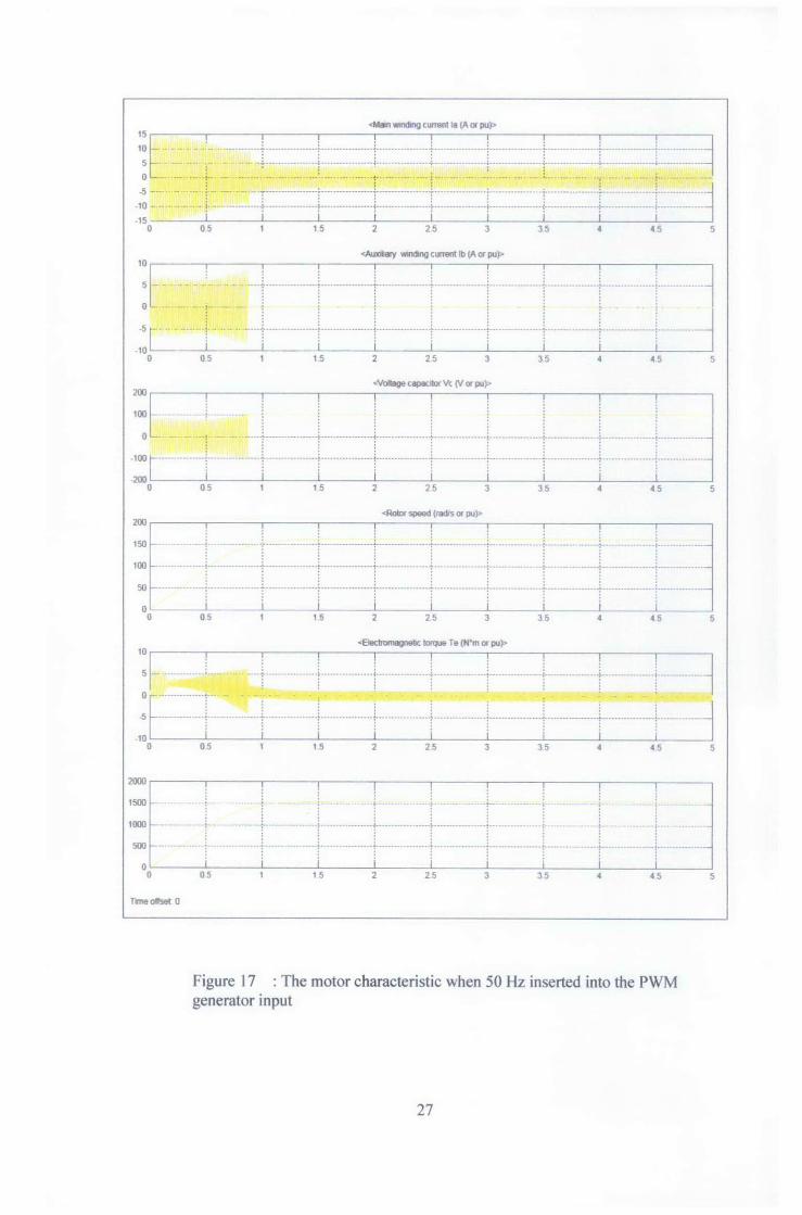
The characteristic of the 75% and 100% of full load can be observed in this
simulation. For conclusion, the speed control method using PWM to control the
voltage frequency has been studied, simulated and tested. It is proven that the
technique can successfully control the speed of single-phase induction motor.
v

ACKNOWLEDGEMENT
I would like to praise Allah the Almighty, who gives me strengths to complete my
Final Year Project, entitled - Speed Control of Single-phase Induction Motor. My
deepest gratitude goes to Mr Mohd Fakhizan Romlie as kindly being my great
supervisor for his guiding, sharing and teaching me to undergo this project.
I would like to express the warmest and greatest gratitude, appreciation to all
parties who have contributed towards the success of this project. I was indebted to
many individuals who contributed to the development of my project. Special thanks
to Hafizuddin Razali and Mohd Hakim Mohd Nor for helping me throughout the
project.
Next, to all lecturers and staffs of Universiti Teknologi PETRONAS,
especially Electrical & Electronics Engineering Department where I was trained with
essential skills and knowledge in order to be a well rounded student. Many thanks to
Ms. Siti Hawa Tahir for the guidance and effort during the project.
Last but not least, to my beloved parents, Mrs Zainab Ahmad, fellow friends
and community of Universiti Teknologi PETRONAS who directly or indirectly
involves in completing the project.
Thank You.
vi
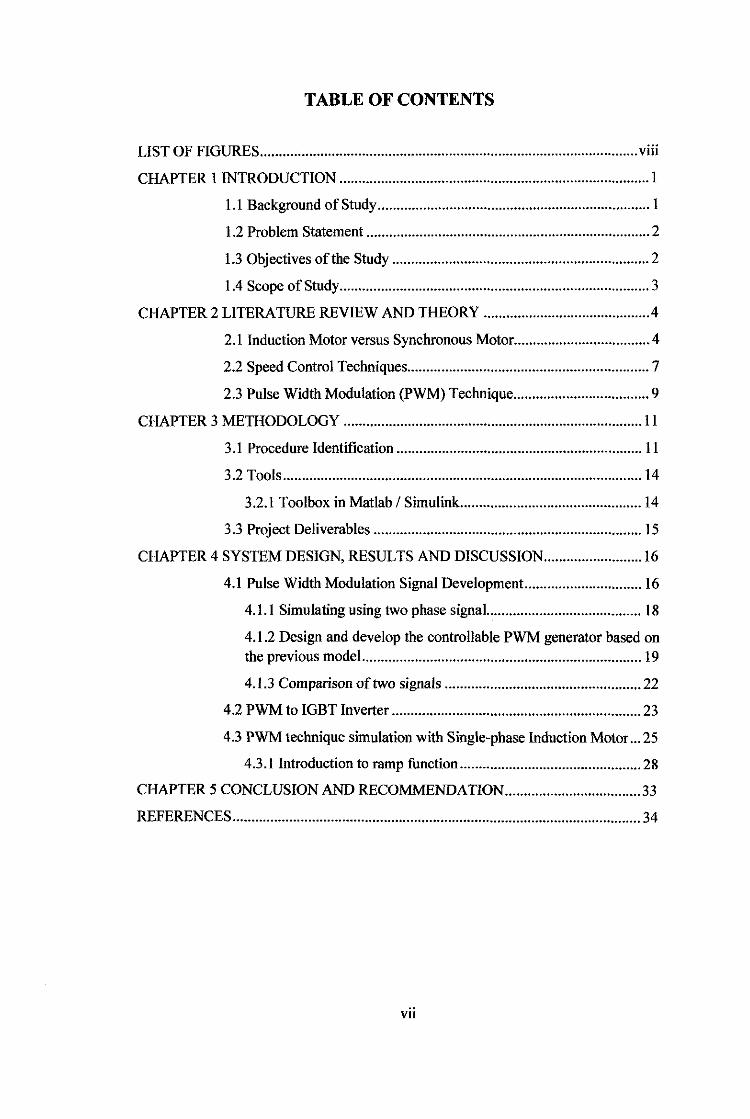
TABLE OF CONTENTS
LIST OF FIGURES .................................................................................................... viii
CHAPTER I INTRODUCTION .................................................................................. 1
1.1 Background of Study ........................................................................ I
1.2 Problem Statement ........................................................................... 2
1.3 Objectives of the Study .................................................................... 2
1.4 Scope of Study .................................................................................. 3
CHAPTER 2 LITERATURE REVIEW AND THEORY ........................................... .4
2.1 Induction Motor versus Synchronous Motor .................................... 4
2.2 Speed Control Techniques ................................................................ 7
2.3 Pulse Width Modulation (PWM) Technique .................................... 9
CHAPTER 3 METHODOLOGY ............................................................................... 11
3 .I Procedure Identification ................................................................. 11
3.2 Tools ............................................................................................... 14
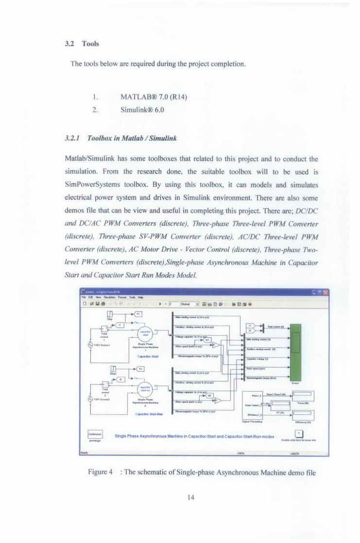
3.2.1 Toolbox in Matlab I Simulink ................................................ 14
3.3 Project Deliverables ....................................................................... 15
CHAPTER 4 SYSTEM DESIGN, RESULTS AND DISCUSSION .......................... 16
4.1 Pulse Width Modulation Signal Development ............................... l6
4.1.1 Simulating using two phase signaL ....................................... 18
4.1.2 Design and develop the controllable PWM generator based on the previous model .......................................................................... l9
4.1.3 Comparison of two signals .................................................... 22
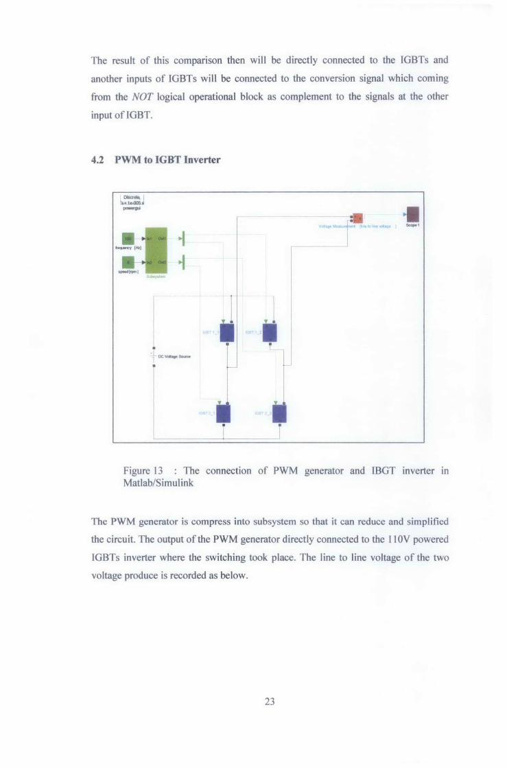
4.2 PWM to IGBT Inverter .................................................................. 23
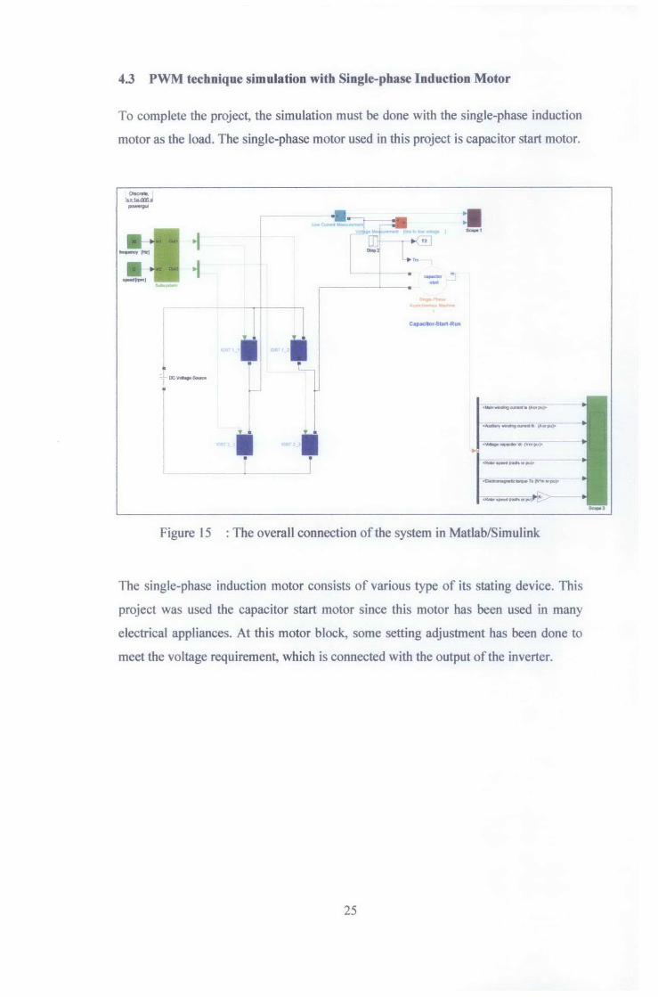
4.3 PWM technique simulation with Single-phase Induction Motor ... 25
4.3.1 Introduction to ramp function ................................................ 28
CHAPTER 5 CONCLUSION AND RECOMMENDATION .................................... 33
REFERENCES ............................................................................................................ 34
VII
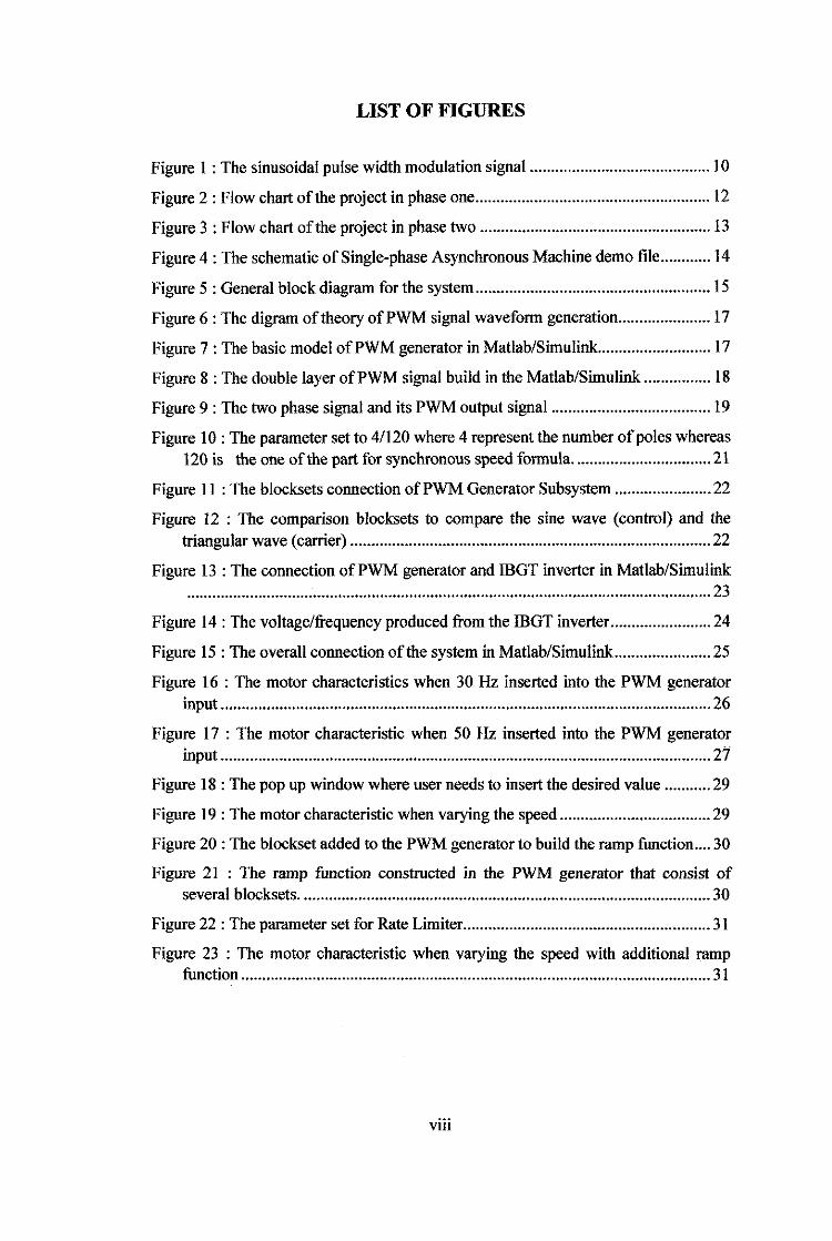
LIST OF FIGURES
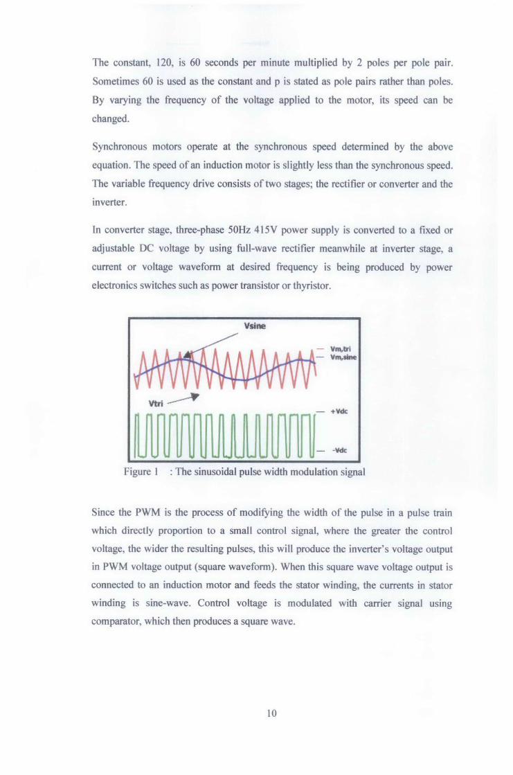
Figure 1 : The sinusoidal pulse width modulation signal ........................................... I 0
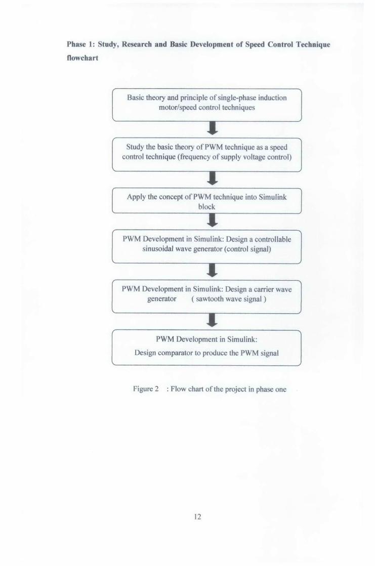
Figure 2: Flow chart of the project in phase one ........................................................ 12
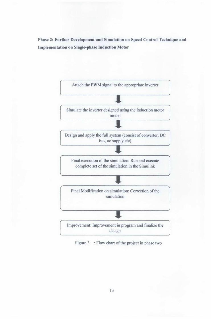
Figure 3 : Flow chart of the project in phase two ....................................................... 13
Figure 4: The schematic of Single-phase Asynchronous Machine demo file ............ l4
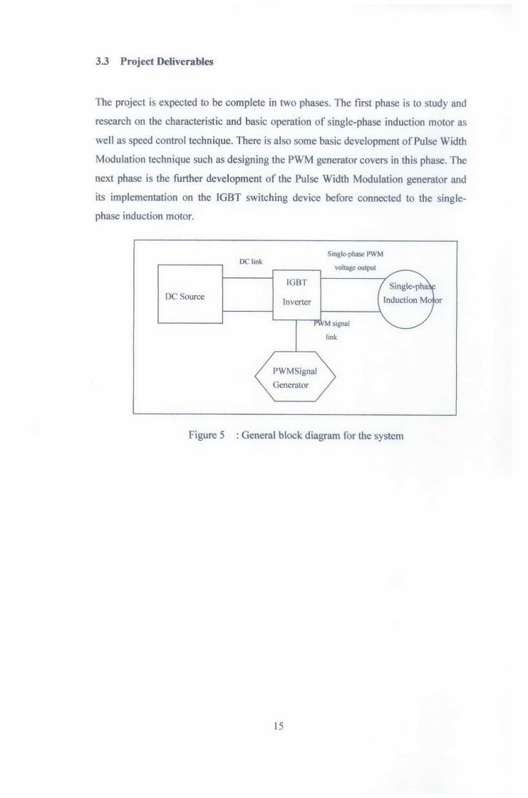
Figure 5 : General block diagram for the system ........................................................ 15
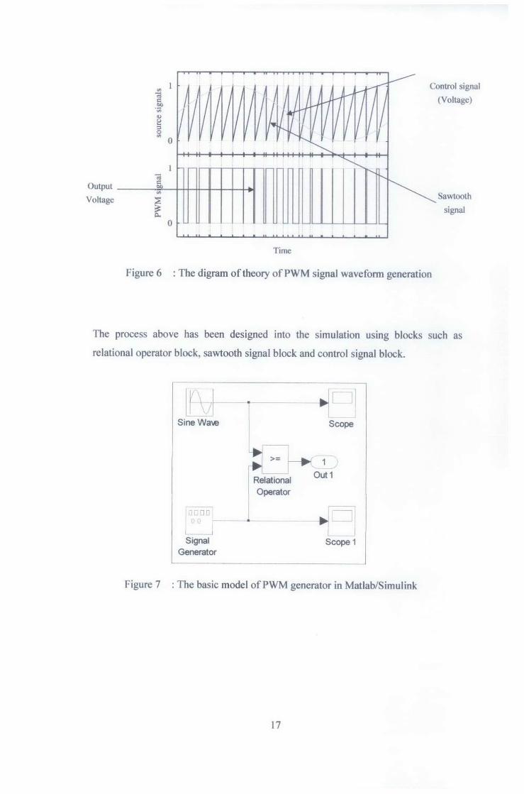
Figure 6 : The digram of theory of PWM signal waveform generation ...................... 17
Figure 7 : The basic model ofPWM generator in Matlab/Simulink ........................... 17
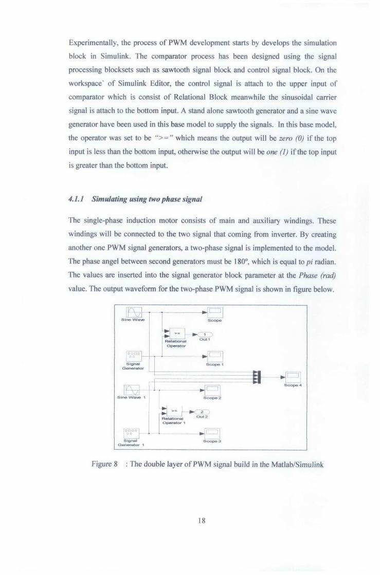
Figure 8 : The double layer ofPWM signal build in the Matlab/Simulink ................ 18
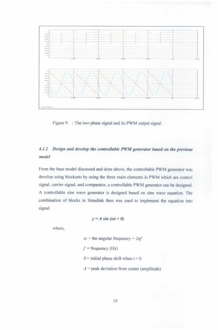
Figure 9 : The two phase signal and its PWM output signal ...................................... 19
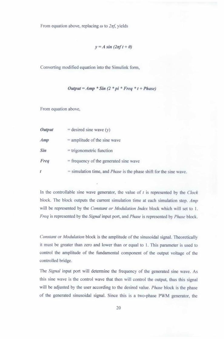
Figure 10: The parameter set to 4/120 where 4 represent the number of poles whereas 120 is the one of the part for synchronous speed formula ................................. 21
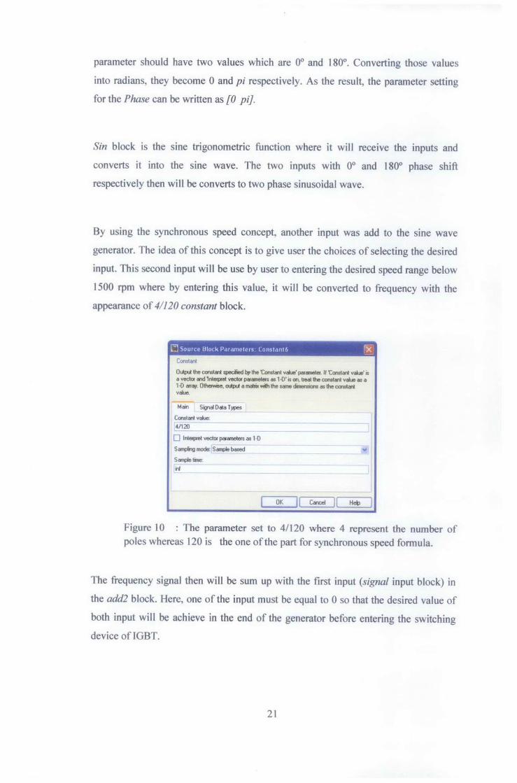
Figure 11 : The blocksets connection of PWM Generator Subsystem ....................... 22
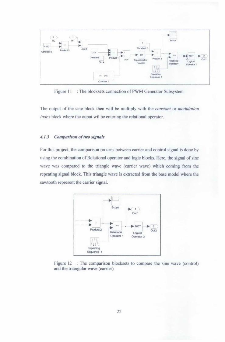
Figure 12 : The comparison blocksets to compare the sine wave (control) and the triangular wave (carrier) ...................................................................................... 22
Figure 13: The connection ofPWM generator and ffiGT inverter in Matlab/Simulink ............................................................................................................................. 23
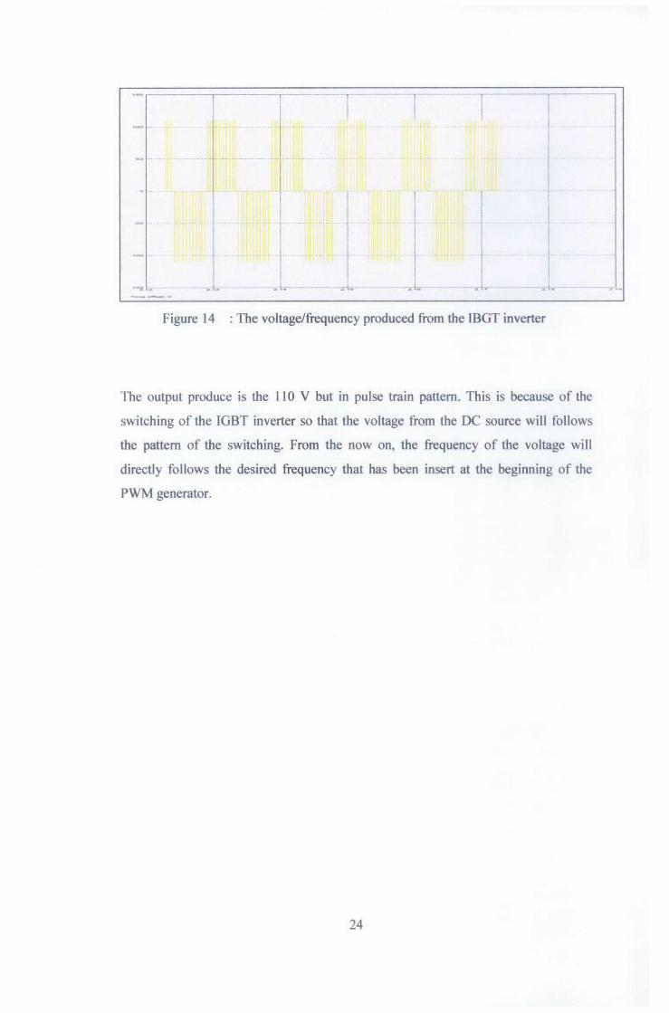
Figure 14 : The voltage/frequency produced from the IBGT inverter. ....................... 24
Figure 15 :The overall connection of the system in Matlab/Simulink ....................... 25
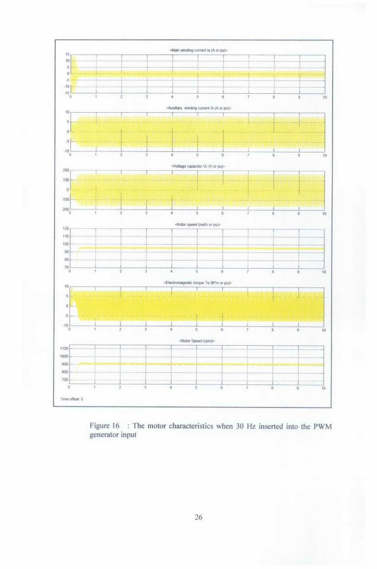
Figure 16 : The motor characteristics when 30 Hz inserted into the PWM generator input ..................................................................................................................... 26
Figure 17 : The motor characteristic when 50 Hz inserted into the PWM generator input ..................................................................................................................... 21
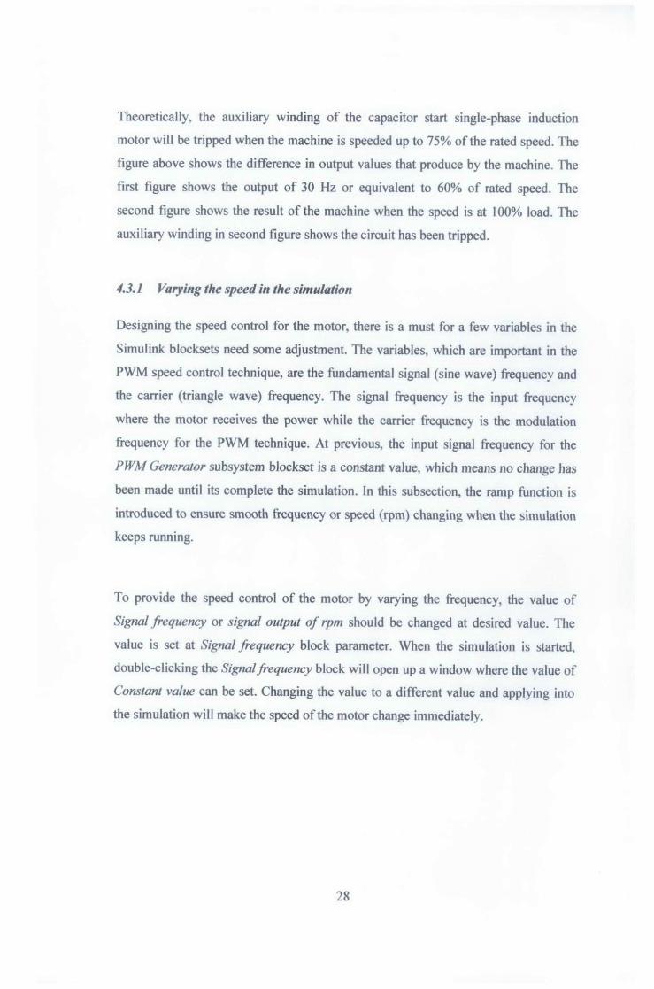
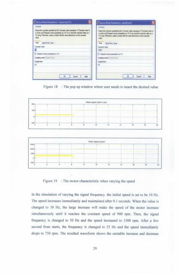
Figure 18 : The pop up window where user needs to insert the desired value ........... 29
Figure 19 : The motor characteristic when varying the speed .................................... 29
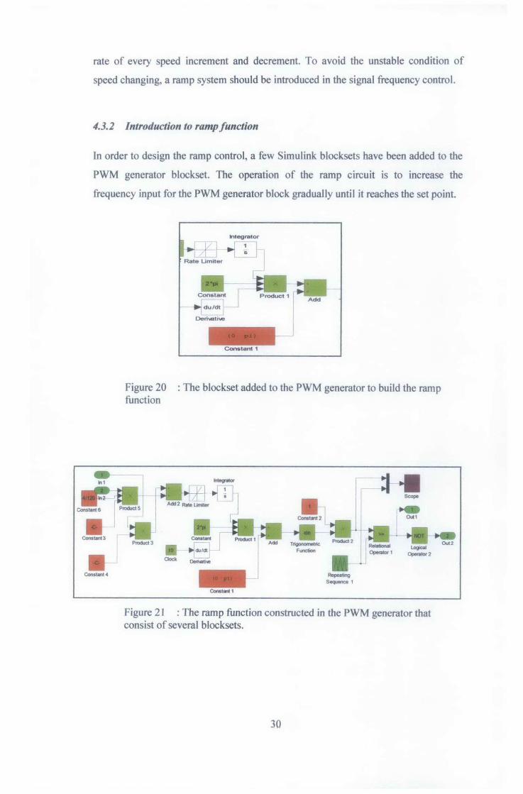
Figure 20 : The b1ockset added to the PWM generator to build the ramp function .... 30
Figure 21 : The ramp function constructed in the PWM generator that consist of several blocksets .................................................................................................. 30
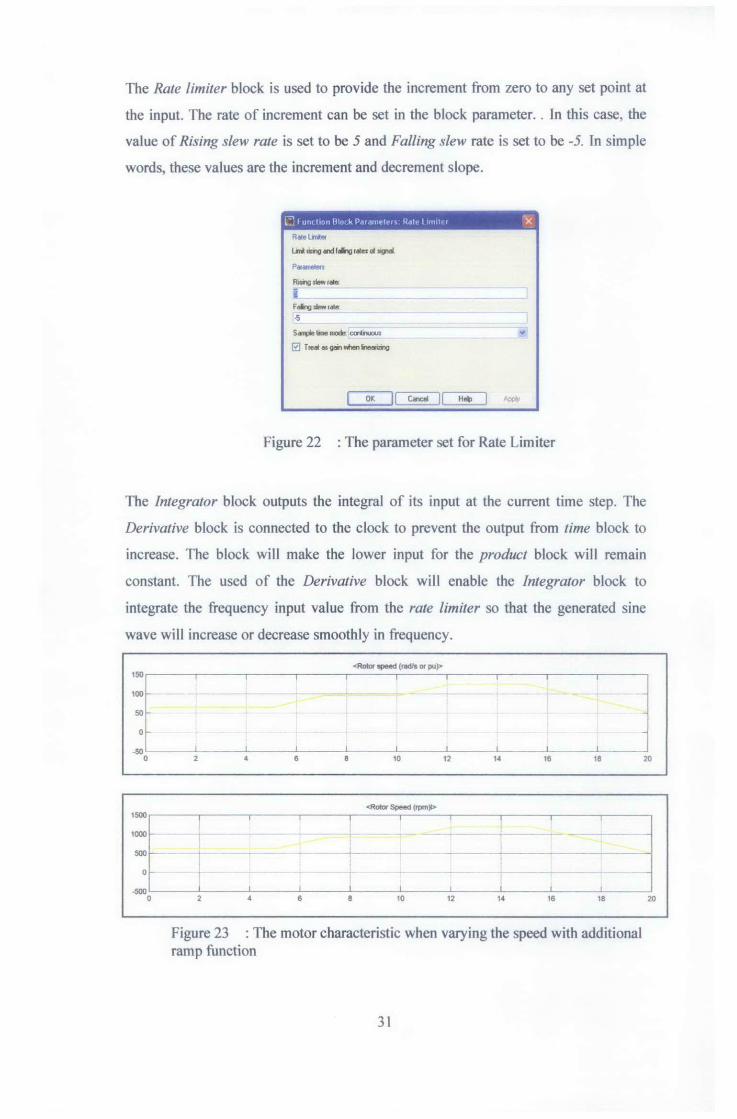
Figure 22 : The parameter set for Rate Limiter ........................................................... 31
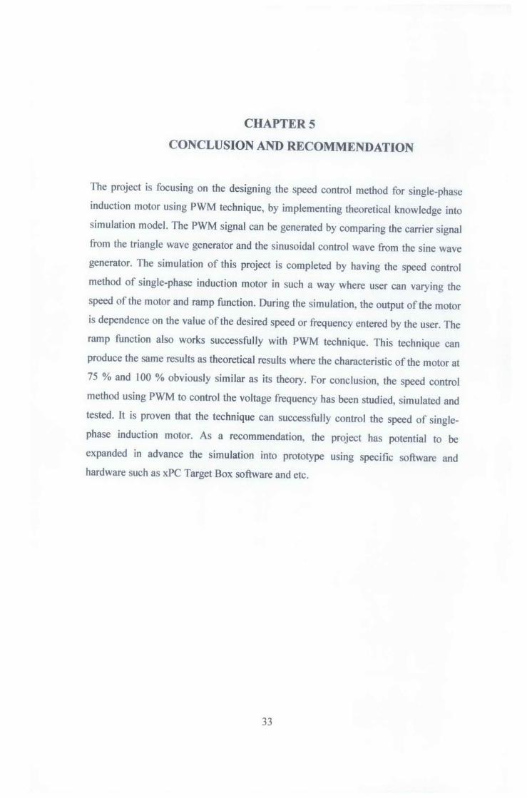
Figure 23 : The motor characteristic when varying the speed with additional ramp function ................................................................................................................ 31
viii
1.1 Background of Study
CHAPTER I
INTRODUCTION
In the fast growing of small and medium enterprise industries in Malaysia, the small
electrical machines that used single-phase induction motors as its prime movers have
been gaining prominence and their applications are becoming wider. Research and
innovation of speed control of single-phase induction motor against various load has
improved machines performance. Speed modulation of a single-phase induction
motor is usually achieved either by non-electrical means, such as throttling the
mechanical output from the motor while it continues to run at full speed, or by
switching windings to change the number of motor poles for different operating
condition as required [l]. Only a few alternatives have been revealed as to the use of
variable frequency converters to achieve continuous variable speed single-phase
induction motor operation. One of these approaches uses a single-phase converter to
control the phase angle of the voltage applied to the motor auxiliary winding, while
the main winding remains connected to the ac supply. These investigations have
shown that a standard single-phase induction motor has a quite limited performance,
and that while controlling the phase angle of the voltage applied to the auxiliary
winding can achieve variable speed operation [2]. The target of this project is to
conduct research on speed control of single-phase induction motor by using certain
techniques of controlling the speed and then come up with simulation model to
control the speed of single-phase induction motor using the technique studied.
1.2 Problem Statement
Attachment of single-phase induction motor to the various loads basically gives some
effects. Usually, for this type of motor, there is no speed control since the motor is
always run daily. But, for certain application, such as prime mover for mixer, the
motor needs to have its own speed controL The adjustment of its speed in improper
way will lead to gain some effects in the performance of the motor in the long period
of time. There are a few techniques available to control the speed of single-phase
induction motor such as controlling rotor resistance, controlling input voltage,
varying no of pole and varying electrical frequency. Varying rotor resistance can
control the speed of the motor but it will produce rotor ohmic losses as rotor
resistance change. Small range speed control of the induction motor can be
implemented by decreasing the magnitude of input voltage. However, the efficiency
of the motor will decrease simultaneously with decrement in speed and overheating
the motor. Changing the number of poles can be used to control the speed of the
motor but it may not practical since it may involve huge modification at the stator
pole. Varying stator electrical frequency offers the option of changing synchronous
speed continuously rather than the modification resulting from pole changing. This
project conducted to control the speed of single-phase induction motor without results
in the efficiency penalty or effects to the motor.
1.3 Objectives of the Study
Objectives of the study are:
i) To study the speed control technique of single-phase induction motor
ii) To model and simulate the speed control of a single-phase induction motor
by using IGBTs and implementing PWM technique for switching of the
IGBTs.
2